EP2983288B1 - Drive circuit for a permanent magnet motor - Google Patents
Drive circuit for a permanent magnet motor Download PDFInfo
- Publication number
- EP2983288B1 EP2983288B1 EP15180248.5A EP15180248A EP2983288B1 EP 2983288 B1 EP2983288 B1 EP 2983288B1 EP 15180248 A EP15180248 A EP 15180248A EP 2983288 B1 EP2983288 B1 EP 2983288B1
- Authority
- EP
- European Patent Office
- Prior art keywords
- diode
- output terminal
- switch
- terminal
- voltage output
- Prior art date
- Legal status (The legal status is an assumption and is not a legal conclusion. Google has not performed a legal analysis and makes no representation as to the accuracy of the status listed.)
- Active
Links
- 238000006243 chemical reaction Methods 0.000 claims description 82
- 230000002457 bidirectional effect Effects 0.000 claims description 54
- 238000004804 winding Methods 0.000 claims description 26
- XUIMIQQOPSSXEZ-UHFFFAOYSA-N Silicon Chemical compound [Si] XUIMIQQOPSSXEZ-UHFFFAOYSA-N 0.000 claims description 21
- 229910052710 silicon Inorganic materials 0.000 claims description 21
- 239000010703 silicon Substances 0.000 claims description 21
- 230000001360 synchronised effect Effects 0.000 description 22
- 238000010586 diagram Methods 0.000 description 7
- XLYOFNOQVPJJNP-UHFFFAOYSA-N water Substances O XLYOFNOQVPJJNP-UHFFFAOYSA-N 0.000 description 3
- 230000005355 Hall effect Effects 0.000 description 1
- 230000003247 decreasing effect Effects 0.000 description 1
- 230000000694 effects Effects 0.000 description 1
- 230000005611 electricity Effects 0.000 description 1
- 230000001939 inductive effect Effects 0.000 description 1
- 230000004048 modification Effects 0.000 description 1
- 238000012986 modification Methods 0.000 description 1
- 230000010355 oscillation Effects 0.000 description 1
Images

Classifications
-
- H—ELECTRICITY
- H02—GENERATION; CONVERSION OR DISTRIBUTION OF ELECTRIC POWER
- H02P—CONTROL OR REGULATION OF ELECTRIC MOTORS, ELECTRIC GENERATORS OR DYNAMO-ELECTRIC CONVERTERS; CONTROLLING TRANSFORMERS, REACTORS OR CHOKE COILS
- H02P6/00—Arrangements for controlling synchronous motors or other dynamo-electric motors using electronic commutation dependent on the rotor position; Electronic commutators therefor
- H02P6/14—Electronic commutators
- H02P6/16—Circuit arrangements for detecting position
-
- H—ELECTRICITY
- H02—GENERATION; CONVERSION OR DISTRIBUTION OF ELECTRIC POWER
- H02P—CONTROL OR REGULATION OF ELECTRIC MOTORS, ELECTRIC GENERATORS OR DYNAMO-ELECTRIC CONVERTERS; CONTROLLING TRANSFORMERS, REACTORS OR CHOKE COILS
- H02P6/00—Arrangements for controlling synchronous motors or other dynamo-electric motors using electronic commutation dependent on the rotor position; Electronic commutators therefor
- H02P6/08—Arrangements for controlling the speed or torque of a single motor
-
- H—ELECTRICITY
- H01—ELECTRIC ELEMENTS
- H01L—SEMICONDUCTOR DEVICES NOT COVERED BY CLASS H10
- H01L23/00—Details of semiconductor or other solid state devices
- H01L23/48—Arrangements for conducting electric current to or from the solid state body in operation, e.g. leads, terminal arrangements ; Selection of materials therefor
- H01L23/488—Arrangements for conducting electric current to or from the solid state body in operation, e.g. leads, terminal arrangements ; Selection of materials therefor consisting of soldered or bonded constructions
- H01L23/49—Arrangements for conducting electric current to or from the solid state body in operation, e.g. leads, terminal arrangements ; Selection of materials therefor consisting of soldered or bonded constructions wire-like arrangements or pins or rods
-
- G—PHYSICS
- G01—MEASURING; TESTING
- G01B—MEASURING LENGTH, THICKNESS OR SIMILAR LINEAR DIMENSIONS; MEASURING ANGLES; MEASURING AREAS; MEASURING IRREGULARITIES OF SURFACES OR CONTOURS
- G01B7/00—Measuring arrangements characterised by the use of electric or magnetic techniques
- G01B7/003—Measuring arrangements characterised by the use of electric or magnetic techniques for measuring position, not involving coordinate determination
-
- G—PHYSICS
- G01—MEASURING; TESTING
- G01D—MEASURING NOT SPECIALLY ADAPTED FOR A SPECIFIC VARIABLE; ARRANGEMENTS FOR MEASURING TWO OR MORE VARIABLES NOT COVERED IN A SINGLE OTHER SUBCLASS; TARIFF METERING APPARATUS; MEASURING OR TESTING NOT OTHERWISE PROVIDED FOR
- G01D5/00—Mechanical means for transferring the output of a sensing member; Means for converting the output of a sensing member to another variable where the form or nature of the sensing member does not constrain the means for converting; Transducers not specially adapted for a specific variable
- G01D5/12—Mechanical means for transferring the output of a sensing member; Means for converting the output of a sensing member to another variable where the form or nature of the sensing member does not constrain the means for converting; Transducers not specially adapted for a specific variable using electric or magnetic means
- G01D5/14—Mechanical means for transferring the output of a sensing member; Means for converting the output of a sensing member to another variable where the form or nature of the sensing member does not constrain the means for converting; Transducers not specially adapted for a specific variable using electric or magnetic means influencing the magnitude of a current or voltage
- G01D5/142—Mechanical means for transferring the output of a sensing member; Means for converting the output of a sensing member to another variable where the form or nature of the sensing member does not constrain the means for converting; Transducers not specially adapted for a specific variable using electric or magnetic means influencing the magnitude of a current or voltage using Hall-effect devices
-
- G—PHYSICS
- G01—MEASURING; TESTING
- G01R—MEASURING ELECTRIC VARIABLES; MEASURING MAGNETIC VARIABLES
- G01R33/00—Arrangements or instruments for measuring magnetic variables
- G01R33/0011—Arrangements or instruments for measuring magnetic variables comprising means, e.g. flux concentrators, flux guides, for guiding or concentrating the magnetic flux, e.g. to the magnetic sensor
-
- G—PHYSICS
- G01—MEASURING; TESTING
- G01R—MEASURING ELECTRIC VARIABLES; MEASURING MAGNETIC VARIABLES
- G01R33/00—Arrangements or instruments for measuring magnetic variables
- G01R33/0023—Electronic aspects, e.g. circuits for stimulation, evaluation, control; Treating the measured signals; calibration
- G01R33/0029—Treating the measured signals, e.g. removing offset or noise
-
- G—PHYSICS
- G01—MEASURING; TESTING
- G01R—MEASURING ELECTRIC VARIABLES; MEASURING MAGNETIC VARIABLES
- G01R33/00—Arrangements or instruments for measuring magnetic variables
- G01R33/02—Measuring direction or magnitude of magnetic fields or magnetic flux
-
- G—PHYSICS
- G01—MEASURING; TESTING
- G01R—MEASURING ELECTRIC VARIABLES; MEASURING MAGNETIC VARIABLES
- G01R33/00—Arrangements or instruments for measuring magnetic variables
- G01R33/02—Measuring direction or magnitude of magnetic fields or magnetic flux
- G01R33/06—Measuring direction or magnitude of magnetic fields or magnetic flux using galvano-magnetic devices
- G01R33/07—Hall effect devices
- G01R33/072—Constructional adaptation of the sensor to specific applications
-
- H—ELECTRICITY
- H01—ELECTRIC ELEMENTS
- H01L—SEMICONDUCTOR DEVICES NOT COVERED BY CLASS H10
- H01L23/00—Details of semiconductor or other solid state devices
- H01L23/48—Arrangements for conducting electric current to or from the solid state body in operation, e.g. leads, terminal arrangements ; Selection of materials therefor
- H01L23/488—Arrangements for conducting electric current to or from the solid state body in operation, e.g. leads, terminal arrangements ; Selection of materials therefor consisting of soldered or bonded constructions
- H01L23/495—Lead-frames or other flat leads
- H01L23/49517—Additional leads
- H01L23/4952—Additional leads the additional leads being a bump or a wire
-
- H—ELECTRICITY
- H02—GENERATION; CONVERSION OR DISTRIBUTION OF ELECTRIC POWER
- H02K—DYNAMO-ELECTRIC MACHINES
- H02K11/00—Structural association of dynamo-electric machines with electric components or with devices for shielding, monitoring or protection
- H02K11/04—Structural association of dynamo-electric machines with electric components or with devices for shielding, monitoring or protection for rectification
- H02K11/049—Rectifiers associated with stationary parts, e.g. stator cores
- H02K11/05—Rectifiers associated with casings, enclosures or brackets
-
- H—ELECTRICITY
- H02—GENERATION; CONVERSION OR DISTRIBUTION OF ELECTRIC POWER
- H02K—DYNAMO-ELECTRIC MACHINES
- H02K11/00—Structural association of dynamo-electric machines with electric components or with devices for shielding, monitoring or protection
- H02K11/20—Structural association of dynamo-electric machines with electric components or with devices for shielding, monitoring or protection for measuring, monitoring, testing, protecting or switching
- H02K11/21—Devices for sensing speed or position, or actuated thereby
- H02K11/215—Magnetic effect devices, e.g. Hall-effect or magneto-resistive elements
-
- H—ELECTRICITY
- H02—GENERATION; CONVERSION OR DISTRIBUTION OF ELECTRIC POWER
- H02K—DYNAMO-ELECTRIC MACHINES
- H02K11/00—Structural association of dynamo-electric machines with electric components or with devices for shielding, monitoring or protection
- H02K11/30—Structural association with control circuits or drive circuits
- H02K11/33—Drive circuits, e.g. power electronics
-
- H—ELECTRICITY
- H02—GENERATION; CONVERSION OR DISTRIBUTION OF ELECTRIC POWER
- H02P—CONTROL OR REGULATION OF ELECTRIC MOTORS, ELECTRIC GENERATORS OR DYNAMO-ELECTRIC CONVERTERS; CONTROLLING TRANSFORMERS, REACTORS OR CHOKE COILS
- H02P6/00—Arrangements for controlling synchronous motors or other dynamo-electric motors using electronic commutation dependent on the rotor position; Electronic commutators therefor
- H02P6/20—Arrangements for starting
-
- H—ELECTRICITY
- H02—GENERATION; CONVERSION OR DISTRIBUTION OF ELECTRIC POWER
- H02P—CONTROL OR REGULATION OF ELECTRIC MOTORS, ELECTRIC GENERATORS OR DYNAMO-ELECTRIC CONVERTERS; CONTROLLING TRANSFORMERS, REACTORS OR CHOKE COILS
- H02P6/00—Arrangements for controlling synchronous motors or other dynamo-electric motors using electronic commutation dependent on the rotor position; Electronic commutators therefor
- H02P6/30—Arrangements for controlling the direction of rotation
-
- H—ELECTRICITY
- H02—GENERATION; CONVERSION OR DISTRIBUTION OF ELECTRIC POWER
- H02P—CONTROL OR REGULATION OF ELECTRIC MOTORS, ELECTRIC GENERATORS OR DYNAMO-ELECTRIC CONVERTERS; CONTROLLING TRANSFORMERS, REACTORS OR CHOKE COILS
- H02P7/00—Arrangements for regulating or controlling the speed or torque of electric DC motors
- H02P7/03—Arrangements for regulating or controlling the speed or torque of electric DC motors for controlling the direction of rotation of DC motors
- H02P7/05—Arrangements for regulating or controlling the speed or torque of electric DC motors for controlling the direction of rotation of DC motors by means of electronic switching
-
- H—ELECTRICITY
- H02—GENERATION; CONVERSION OR DISTRIBUTION OF ELECTRIC POWER
- H02P—CONTROL OR REGULATION OF ELECTRIC MOTORS, ELECTRIC GENERATORS OR DYNAMO-ELECTRIC CONVERTERS; CONTROLLING TRANSFORMERS, REACTORS OR CHOKE COILS
- H02P7/00—Arrangements for regulating or controlling the speed or torque of electric DC motors
- H02P7/06—Arrangements for regulating or controlling the speed or torque of electric DC motors for regulating or controlling an individual dc dynamo-electric motor by varying field or armature current
- H02P7/18—Arrangements for regulating or controlling the speed or torque of electric DC motors for regulating or controlling an individual dc dynamo-electric motor by varying field or armature current by master control with auxiliary power
- H02P7/24—Arrangements for regulating or controlling the speed or torque of electric DC motors for regulating or controlling an individual dc dynamo-electric motor by varying field or armature current by master control with auxiliary power using discharge tubes or semiconductor devices
- H02P7/28—Arrangements for regulating or controlling the speed or torque of electric DC motors for regulating or controlling an individual dc dynamo-electric motor by varying field or armature current by master control with auxiliary power using discharge tubes or semiconductor devices using semiconductor devices
- H02P7/285—Arrangements for regulating or controlling the speed or torque of electric DC motors for regulating or controlling an individual dc dynamo-electric motor by varying field or armature current by master control with auxiliary power using discharge tubes or semiconductor devices using semiconductor devices controlling armature supply only
- H02P7/292—Arrangements for regulating or controlling the speed or torque of electric DC motors for regulating or controlling an individual dc dynamo-electric motor by varying field or armature current by master control with auxiliary power using discharge tubes or semiconductor devices using semiconductor devices controlling armature supply only using static converters, e.g. AC to DC
- H02P7/295—Arrangements for regulating or controlling the speed or torque of electric DC motors for regulating or controlling an individual dc dynamo-electric motor by varying field or armature current by master control with auxiliary power using discharge tubes or semiconductor devices using semiconductor devices controlling armature supply only using static converters, e.g. AC to DC of the kind having a thyristor or the like in series with the power supply and the motor
-
- H—ELECTRICITY
- H10—SEMICONDUCTOR DEVICES; ELECTRIC SOLID-STATE DEVICES NOT OTHERWISE PROVIDED FOR
- H10B—ELECTRONIC MEMORY DEVICES
- H10B61/00—Magnetic memory devices, e.g. magnetoresistive RAM [MRAM] devices
-
- H—ELECTRICITY
- H10—SEMICONDUCTOR DEVICES; ELECTRIC SOLID-STATE DEVICES NOT OTHERWISE PROVIDED FOR
- H10N—ELECTRIC SOLID-STATE DEVICES NOT OTHERWISE PROVIDED FOR
- H10N52/00—Hall-effect devices
-
- H—ELECTRICITY
- H02—GENERATION; CONVERSION OR DISTRIBUTION OF ELECTRIC POWER
- H02P—CONTROL OR REGULATION OF ELECTRIC MOTORS, ELECTRIC GENERATORS OR DYNAMO-ELECTRIC CONVERTERS; CONTROLLING TRANSFORMERS, REACTORS OR CHOKE COILS
- H02P2207/00—Indexing scheme relating to controlling arrangements characterised by the type of motor
- H02P2207/05—Synchronous machines, e.g. with permanent magnets or DC excitation
-
- Y—GENERAL TAGGING OF NEW TECHNOLOGICAL DEVELOPMENTS; GENERAL TAGGING OF CROSS-SECTIONAL TECHNOLOGIES SPANNING OVER SEVERAL SECTIONS OF THE IPC; TECHNICAL SUBJECTS COVERED BY FORMER USPC CROSS-REFERENCE ART COLLECTIONS [XRACs] AND DIGESTS
- Y02—TECHNOLOGIES OR APPLICATIONS FOR MITIGATION OR ADAPTATION AGAINST CLIMATE CHANGE
- Y02P—CLIMATE CHANGE MITIGATION TECHNOLOGIES IN THE PRODUCTION OR PROCESSING OF GOODS
- Y02P80/00—Climate change mitigation technologies for sector-wide applications
- Y02P80/10—Efficient use of energy, e.g. using compressed air or pressurized fluid as energy carrier
Definitions
- This invention relates to a driver or drive circuit for a permanent magnetic motor, especially for a low-power permanent magnetic motor as used, for example, to drive a small fan or a small water pump.
- the stator produces an alternating magnetic field causing the permanent magnetic rotor to be oscillated.
- the amplitude of the oscillation of the rotor increases until the rotor begins to rotate, and finally the rotor is accelerated to rotate in synchronism with the alternating magnetic field of the stator.
- a starting point of the motor is set to be low, which results in that the motor cannot operate at a relatively high working point, thus the efficiency is low.
- the rotor cannot be ensured to rotate in a same direction every time since a stop or stationary position of the permanent magnetic rotor is not fixed. Accordingly, in applications such as a fan and water pump, the impeller driven by the rotor has straight radial vanes, which results in a low operational efficiency of the fan and water pump.
- Figure 1 shows a conventional drive circuit for a synchronous motor, which allows a rotor to rotate in a same predetermined direction in every time it starts.
- a stator winding 1 of the motor is connected in series with a TRIAC between two terminals M and N of an AC power source VM, and an AC power source VM is converted by a conversion circuit DC into a direct current voltage and the direct current is supplied to a position sensor H.
- a magnetic pole position of a rotor in the motor is detected by the position sensor H, and an output signal Vh of the position sensor H is connected to a switch control circuit PC to control the bidirectional thyristor T.
- Figure 2 shows a waveform of the drive circuit.
- the AC power source supplies power for the conversion circuit DC so that the conversion circuit DC constantly outputs and supplies power for the position sensor H (referring to a signal VH in Figure 2 ).
- the AC power source is commercial electricity of about 200V
- the electric energy consumed by two resistors R2 and R3 in the conversion circuit DC is more than the electric energy consumed by the motor. Examples of conventional drive circuits are disclosed in US6114827 and US2008/0100255 , for instance.
- the present invention provides a drive circuit of a permanent magnet motor comprising a stator and a permanent magnet rotor, the stator comprising a stator core and a stator winding wound on the stator core and adapted to be connected in series with an AC power source between a first node and a second node, the drive circuit comprising: a controllable bidirectional AC switch connected between the first node and the second node, the controllable bidirectional AC switch, if switched on, being adapted to remain on in the absence of a drive current; an AC-DC conversion circuit connected in parallel with the controllable bidirectional AC switch between the first node and the second node, wherein there is no current flowing through the AC-DC conversion circuit when the first node and the second node are shorted by the controllable bidirectional AC switch; a position sensor configured to detect a magnetic pole position of the permanent magnet rotor; and characterized by a switch control circuit configured to control the controllable bidirectional AC switch to be switched between a conductive state and a
- controllable bidirectional AC switch includes a TRIAC, or may include two silicon control rectifiers reversely connected in parallel.
- a first anode of the TRIAC is connected to the first node
- a second anode of the TRIAC is connected to the second node
- a control electrode of the TRIAC is connected to the switch control circuit.
- the AC-DC conversion circuit comprises a full wave rectifying circuit having a high voltage output terminal and a low voltage output terminal.
- a zener diode is connected between the high voltage output terminal and the low voltage output terminal.
- the AC-DC conversion circuit comprises a first diode and a second diode which are reversely connected in parallel between the first node and the second node respectively via a first resistor and a second resistor, a high voltage output terminal of the AC-DC conversion circuit is formed at a connection point of the first resistor and a cathode of the first diode, a low voltage output terminal of the AC-DC conversion circuit is formed at a connection point of the second resistor and an anode of the second diode, and the first diode and the second diode are zener diodes.
- the AC-DC conversion circuit comprises a first resistor connected in series with the full wave bridge rectifier between the first node and the second node.
- the full wave bridge rectifier comprises two rectifier branches connected in parallel, one of the two rectifier branches comprising a first diode and a third diode reversely connected in series, and the other of the two rectifier branches comprises a second diode and a fourth diode reversely connected in series, the high voltage output terminal of the AC-DC conversion circuit is formed at a connection point of a cathode of the first diode and a cathode of the third diode, and the low voltage output terminal of the AC-DC conversion circuit is formed at a connection point of an anode of the second diode and an anode of the fourth diode.
- the second diode and the fourth diode are zener diodes.
- the full wave bridge rectifier comprises two rectifier branches connected in parallel, one of the two rectifier branches comprises two silicon control rectifiers reversely connected in series, and the other of the two rectifier branches comprises a second diode and a fourth diode reversely connected in series, the high voltage output terminal of the AC-DC conversion circuit is formed at a connection point of cathodes of the two silicon control rectifiers, and the low voltage output terminal of the AC-DC conversion circuit is formed at a connection point of an anode of the second diode and an anode of the fourth diode.
- a first signal terminal connects the cathodes of the two silicon control rectifiers and a second signal terminal connects the control terminals of the two silicon control rectifiers, wherein the first signal terminal is connected to a reference voltage; a control signal input from the second signal terminal ensures the two silicon control rectifiers to be switched between a switch-on state and a switch-off state in a predetermined way in a case that the drive circuit operates normally, or a control signal input from the second signal terminal enables the two silicon control rectifiers to be switched off in a case that the drive circuit fails.
- the AC-DC conversion circuit has a high voltage output terminal and a low voltage output terminal
- the switch control circuit comprises a first terminal connected to the high voltage output terminal, a second terminal connected to an output terminal of the position sensor, and a third terminal connected to the control electrode of the controllable bidirectional AC switch
- the high voltage output terminal of the AC-DC conversion circuit is connected to a positive power supply terminal of the position sensor
- a low voltage output terminal of the AC-DC conversion circuit is connected to a negative power supply terminal of the position sensor.
- a preset steering circuit is disposed between the third terminal of the switch control circuit and the control electrode of the controllable bidirectional AC switch, and the preset steering circuit comprises a first jumper switch connected between the third terminal and the control electrode of the controllable bidirectional AC switch, and a second jumper switch and an inverter connected in series which are connected in parallel with the first jumper switch between the third terminal and the control electrode.
- the switch control circuit further comprises a third resistor, a fourth resistor, and a fifth diode and a sixth diode reversely connected in series between the output terminal of the position sensor and the control electrode of the controllable bidirectional AC switch; a cathode of the fifth diode is connected to the output terminal of the position sensor, and a cathode of the sixth diode is connected to the control electrode of the controllable bidirectional AC switch; one terminal of the third resistor is connected to the high voltage output terminal of the AC-DC conversion circuit, and the other terminal of the third resistor is connected to a connection point of an anode of the fifth diode and an anode of the sixth diode; and two terminals of the fourth resistor are connected to a cathode of the fifth diode and a cathode of the sixth diode respectively.
- the switch control circuit further comprises a third resistor, a fifth diode, and a fourth resistor and a sixth diode connected in series between the output terminal of the position sensor and the control electrode of the controllable bidirectional AC switch; an anode of the sixth diode is connected to the control electrode of the controllable bidirectional AC switch; one terminal of the third resistor is connected to the high voltage output terminal of the AC-DC conversion circuit, and the other terminal of the third resistor is connected to a connection point of an anode of the fifth diode and the output terminal of the position sensor; and a cathode of the fifth diode is connected to the control electrode of the controllable bidirectional AC switch.
- the switch control circuit further comprises a third resistor, an NPN transistor, and a fourth resistor and a fifth diode connected in series between the output terminal of the position sensor and the control electrode of the controllable bidirectional AC switch; a cathode of the fifth diode is connected to the output terminal of the position sensor; one terminal of the third resistor is connected to the high voltage output terminal of the AC-DC conversion circuit, and the other terminal of the third resistor is connected to the output terminal of the position sensor; and a base of the NPN transistor is connected to the output terminal of the position sensor, an emitter of the NPN transistor is connected to an anode of the fifth diode, and a collector of the NPN transistor is connected to the high voltage output terminal of the AC-DC conversion circuit.
- a non-uniform gap is formed between the stator and the permanent magnet rotor, and a polar axis of the permanent magnet rotor has an angular offset relative to a central axis of the stator when the permanent magnet rotor is at rest.
- FIG. 3 schematically shows a synchronous motor according to an embodiment of the present invention.
- the synchronous motor 10 includes a stator 12 and a permanent magnet rotor 14 rotatably disposed between magnetic poles of the stator 12, and the stator 12 includes a stator core 15 and a stator winding 16 wound on the stator core 15.
- the rotor 14 includes at least one permanent magnet forming at least one pair of permanent magnetic poles with opposite polarities, and the rotor 14 operates at a constant rotational speed of 60f/p during a steady state phase in a case that the stator winding 16 is connected to an AC power supply, where f is a frequency of the AC power supply and p is the number of pole pairs of the rotor.
- Non-uniform gap 18 is formed between the magnetic poles of the stator 12 and the permanent magnetic poles of the rotor 14 so that a polar axis R of the rotor 14 has an angular offset ⁇ relative to a central axis S of the stator 12 in a case that the rotor is at rest.
- the rotor 14 may be configured to have a fixed starting direction (a clockwise direction in this embodiment as shown by the arrow in Fig. 3 ) every time the stator winding 16 is energized.
- the stator and the rotor each have two magnetic poles as shown in Figure 3 . It can be understood that, in other embodiments, the stator and the rotor may also have more magnetic poles, such as 4 or 6 magnetic poles.
- a position sensor 20 for detecting the angular position of the rotor is disposed on the stator 12 or at a position near the rotor inside the stator, and the position sensor 20 has an angular offset relative to the central axis S of the stator. Preferably, this angular offset is also ⁇ , as in this embodiment.
- the position sensor 20 is a Hall effect sensor.
- FIG. 4 shows a block diagram of a drive circuit for a synchronous motor according to an embodiment of the present invention.
- the stator winding 16 and the AC power supply 24 are connected in series between two nodes A and B.
- the AC power supply 24 may be a commercial AC power supply with a fixed frequency, such as 50Hz or 60Hz, and a supply voltage may be, for example, 110V, 220V or 230V.
- a controllable bidirectional AC switch 26 is connected between the two nodes A and B, in parallel with the stator winding 16 and the AC power supply 24.
- the controllable bidirectional AC switch 26 is a TRIAC, of which two anodes are connected to the two nodes A and B respectively.
- controllable bidirectional AC switch 26 alternatively may be two silicon control rectifiers reversely connected in parallel, and control circuits may be correspondingly configured to control the two silicon control rectifiers in a preset way.
- An AC-DC conversion circuit 28 is also connected between the two nodes A and B.
- An AC voltage between the two nodes A and B is converted by the AC-DC conversion circuit 28 into a low voltage DC.
- the position sensor 20 may be powered by the low voltage DC output by the AC-DC conversion circuit 28, for detecting the magnetic pole position of the permanent magnet rotor 14 of the synchronous motor 10 and outputting a corresponding signal.
- a switch control circuit 30 is connected to the AC-DC conversion circuit 28, the position sensor 20 and the controllable bidirectional AC switch 26, and is configured to control the controllable bidirectional AC switch 26 to be switched between a switch-on state and a switch-off state in a predetermined way, based on the magnetic pole position of the permanent magnet rotor which is detected by the position sensor and polarity information of the AC power supply 24 which may be obtained from the AC-DC conversion circuit 28, such that the stator winding 16 urges the rotor 14 to rotate only in the above-mentioned fixed starting direction during a starting phase of the motor.
- the controllable bidirectional AC switch 26 in a case that the controllable bidirectional AC switch 26 is switched on, the two nodes A and B are shorted, the AC-DC conversion circuit 28 does not consume electric energy since there is no current flowing through the AC-DC conversion circuit 28, hence, the utilization efficiency of electric energy can be improved significantly.
- FIG. 5 shows a circuit diagram of a drive circuit 40 for a synchronous motor according to a first embodiment of the present disclosure.
- the stator winding 16 of the synchronous motor is connected in series with the AC power supply 24 between the two nodes A and B.
- a first anode T1 of the TRIAC 26 is connected to the node A, and a second anode T2 of the TRIAC 26 is connected to the node B.
- the AC-DC conversion circuit 28 is connected in parallel with the TRIAC 26 between the two nodes A and B.
- An AC voltage between the two nodes A and B is converted by the AC-DC conversion circuit 28 into a low voltage DC (preferably, low voltage ranges from 3V to 18V).
- the AC-DC conversion circuit 28 includes a first zener diode Z1 and a second zener diode Z2 which are reversely connected in parallel between the two nodes A and B via a first resistor R1 and a second resistor R2 respectively.
- a high voltage output terminal C of the AC-DC conversion circuit 28 is formed at a connection point of the first resistor R1 and a cathode of the first zener diode Z1, and a low voltage output terminal D of the AC-DC conversion circuit 28 is formed at a connection point of the second resistor R2 and an anode of the second zener diode Z2.
- the voltage output terminal C is connected to a positive power supply terminal of the position sensor 20, and the voltage output terminal D is connected to a negative power supply terminal of the position sensor 20.
- Three terminals of the switch control circuit 30 are connected to the high voltage output terminal C of the AC-DC conversion circuit 28, an output terminal HI of the position sensor 20 and a control electrode G of the TRIAC 26 respectively.
- the switch control circuit 30 includes a third resistor R3, a fifth diode D5, and a fourth resistor R4 and a sixth diode D6 connected in series between the output terminal HI of the position sensor 20 and the control electrode G of the controllable bidirectional AC switch 26. An anode of the sixth diode D6 is connected to the control electrode G of the controllable bidirectional AC switch 26.
- One terminal of the third resistor R3 is connected to the high voltage output terminal C of the AC-DC conversion circuit 28, and the other terminal of the third resistor R3 is connected to an anode of the fifth diode D5.
- a cathode of the fifth diode D5 is connected to the control electrode G of the controllable bidirectional AC switch 26.
- Vac indicates a waveform of voltage of the AC power supply 24
- lac indicates a waveform of current flowing through the stator winding 16. Due to the inductive character of the stator winding 16, the waveform of current lac lags behind the waveform of voltage Vac.
- VI indicates a waveform of voltage between two terminals of the first zener diode Z1
- V2 indicates a waveform of voltage between two terminals of the second zener diode Z2
- Vdc indicates a waveform of voltage between two output terminals C and D of the AC-DC conversion circuit 28
- Ha indicates a waveform of a signal output by the output terminal HI of the position sensor 20
- Hb indicates a rotor magnetic field detected by the position sensor 20.
- the output terminal HI outputs a logic high level in a case that the detected rotor magnetic field is North, or the output terminal HI outputs a logic low level in a case that the detected rotor magnetic field is South.
- the supply voltage is gradually increased from a time instant t0 to a time instant t1, the output terminal HI of the position sensor 20 outputs a high level, and a current flows through the resistor R1, the resistor R3, the diode D5 and the control electrode G and the second anode T2 of the TRIAC 26 sequentially.
- the TRIAC 26 is switched on in a case that a drive current flowing through the control electrode G and the second anode T2 is greater than a gate triggering current Ig.
- the TRIAC 26 Since the current flowing through two anodes T1 and T2 of the TRIAC 26 is large enough (which is greater than a holding current Ihold), the TRIAC 26 is kept to be switched on in a case that there is no drive current flowing through the control electrode G and the second anode T2. In a negative half cycle of the AC power supply, after a time instant t3, a current flowing through T1 and T2 is less than the holding current Ihold, the TRIAC 26 is switched off, a current begins to flow through the AC-DC conversion circuit 28, and the output terminal HI of the position sensor 20 outputs a high level again.
- a current flows through the resistor R1, the resistor R3, the diode D5, and the control electrode G and the second anode T2 of the TRIAC 26 sequentially.
- the TRIAC 26 is switched on again, and the current flowing through the stator winding 16 continues to drive the rotor 14 to rotate clockwise.
- the resistors R1 and R2 do not consume electric energy since the two nodes A and B are shorted.
- the rotor magnetic field Hb detected by the position sensor 20 changes to be South from North, the AC power supply is still in the positive half cycle and the TRIAC 26 is switched on, the two nodes A and B are shorted, and there is no current flowing through the AC-DC conversion circuit 28.
- the current flowing through the two anodes T1 and T2 of the TRIAC 26 is gradually decreased, and the TRIAC 26 is switched off at a time instant t5. Then the current flows through the second anode T2 and the control electrode G of the TRIAC 26, the diode D6, the resistor R4, the position sensor 20, the resistor R2 and the stator winding 16 sequentially.
- the TRIAC 26 is switched on again at a time instant t6, the two nodes A and B are shorted again, the resistors R1 and R2 do not consume electric energy, and the output of the position sensor 20 is stopped due to no power is supplied. There is a larger reverse current flowing through the stator winding 16, and the rotor 14 continues to be driven clockwise since the rotor magnetic field is South. From the time instant t5 to the time instant t6, the first zener diode Z1 and the second zener diode Z2 are switched on, hence, there is a voltage output between the two output terminals C and D of the AC-DC conversion circuit 28.
- the AC power supply enters the positive half cycle again, the TRIAC 26 is switched off when the current flowing through the TRIAC 26 crosses zero, and then a voltage of the control circuit is gradually increased.
- a current begins to flow through the AC-DC conversion circuit 28, the output terminal HI of the position sensor 20 outputs a low level, there is no drive current flowing through the control electrode G and the second anode T2 of the TRIAC 26, hence, the TRIAC 26 is switched off. Since the current flowing through the stator winding 16 is very small, nearly no driving force is generated for the rotor 14.
- the power supply is in the positive half cycle, the position sensor outputs a low level, the TRIAC 26 is kept to be switched off after the current crosses zero, and the rotor continues to rotate clockwise due to inertia.
- the rotor may be accelerated to be synchronized with the stator after rotating only one circle after the stator winding is energized.
- FIG. 7 shows a circuit diagram of a drive circuit 42 for a synchronous motor according to an embodiment of the present disclosure.
- the stator winding 16 of the synchronous motor is connected in series with the AC power supply 24 between the two nodes A and B.
- a first anode T1 of the TRIAC 26 is connected to the node A, and a second anode T2 of the TRIAC 26 is connected to the node B.
- the AC-DC conversion circuit 28 is connected in parallel with the TRIAC 26 between the two nodes A and B.
- An AC between the two nodes A and B is converted by the AC-DC conversion circuit 28 into a low voltage DC, preferably, a low voltage ranging from 3V to 18V.
- the AC-DC conversion circuit 28 includes a first resistor R1 and a full wave bridge rectifier connected in series between the two nodes A and B.
- the full wave bridge rectifier includes two rectifier branches connected in parallel, one of the two rectifier branches includes a first diode D1 and a third diode D3 reversely connected in series, and the other of the two rectifier branches includes a second zener diode Z2 and a fourth zener diode Z4 reversely connected in series, the high voltage output terminal C of the AC-DC conversion circuit 28 is formed at a connection point of a cathode of the first diode D1 and a cathode of the third diode D3, and the low voltage output terminal D of the AC-DC conversion circuit 28 is formed at a connection point of an anode of the second zener diode Z2 and an anode of the fourth zener diode Z4.
- the output terminal C is connected to a positive power supply terminal of the position sensor 20, and the output terminal D is connected to a negative power supply terminal of the position sensor 20.
- the switch control circuit 30 includes a third resistor R3, a fourth resistor R4, and a fifth diode D5 and a sixth diode D6 reversely connected in series between the output terminal HI of the position sensor 20 and the control electrode G of the controllable bidirectional AC switch 26.
- a cathode of the fifth diode D5 is connected to the output terminal HI of the position sensor, and a cathode of the sixth diode D6 is connected to the control electrode G of the controllable bidirectional AC switch.
- One terminal of the third resistor R3 is connected to the high voltage output terminal C of the AC-DC conversion circuit, and the other terminal of the third resistor R3 is connected to a connection point of an anode of the fifth diode D5 and an anode of the sixth diode D6.
- Two terminals of the fourth resistor R4 are connected to a cathode of the fifth diode D5 and a cathode of the sixth diode D6 respectively.
- Figure 8 shows a circuit diagram of a drive circuit 44 for a synchronous motor according to a further embodiment of the present invention.
- the drive circuit 44 is similar to the drive circuit 42 in the previous embodiment and, the drive circuit 44 differs from the drive circuit 42 in that, the zener diodes Z2 and Z4 in the drive circuit 42 are replaced by general diodes D2 and D4 in the rectifier of the drive circuit 44.
- a zener diode Z7 is connected between the two output terminals C and D of the AC-DC conversion circuit 28 in the drive circuit 44.
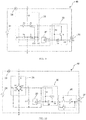
- FIG. 9 shows a circuit diagram of a drive circuit 46 for a synchronous motor according to further embodiment of the present invention.
- the stator winding 16 of the synchronous motor is connected in series with the AC power supply 24 between the two nodes A and B.
- a first anode T1 of the TRIAC 26 is connected to the node A, and a second anode T2 of the TRIAC 26 is connected to the node B.
- the AC-DC conversion circuit 28 is connected in parallel with the TRIAC 26 between the two nodes A and B.
- An AC voltage between the two nodes A and B is converted by the AC-DC conversion circuit 28 into a low voltage DC, preferably, a low voltage ranging from 3V to 18V.
- the AC-DC conversion circuit 28 includes a first resistor R1 and a full wave bridge rectifier connected in series between the two nodes A and B.
- the full wave bridge rectifier includes two rectifier branches connected in parallel, one of the two rectifier branches includes two silicon control rectifiers S1 and S3 reversely connected in series, and the other of the two rectifier branches includes a second diode D2 and a fourth diode D4 reversely connected in series.
- the high voltage output terminal C of the AC-DC conversion circuit 28 is formed at a connection point of a cathode of the silicon control rectifier S1 and a cathode of the silicon control rectifier S3, and the low voltage output terminal D of the AC-DC conversion circuit 28 is formed at a connection point of an anode of the second diode D2 and an anode of the fourth diode D4.
- the output terminal C is connected to a positive power supply terminal of the position sensor 20, and the output terminal D is connected to a negative power supply terminal of the position sensor 20.
- the switch control circuit 30 includes a third resistor R3, an NPN transistor T6, and a fourth resistor R4 and a fifth diode D5 connected in series between the output terminal HI of the position sensor 20 and the control electrode G of the controllable bidirectional AC switch 26.
- a cathode of the fifth diode D5 is connected to the output terminal HI of the position sensor.
- One terminal of the third resistor R3 is connected to the high voltage output terminal C of the AC-DC conversion circuit, and the other terminal of the third resistor R3 is connected to the output terminal HI of the position sensor.
- a base of the NPN transistor T6 is connected to the output terminal HI of the position sensor, an emitter of the NPN transistor T6 is connected to an anode of the fifth diode D5, and a collector of the NPN transistor T6 is connected to the high voltage output terminal C of the AC-DC conversion circuit.
- a reference voltage may be input to the cathodes of the two silicon control rectifiers S1 and S3 via a terminal SC1, and a control signal may be input to control terminals of S1 and S3 via a terminal SC2.
- the rectifiers S1 and S3 are switched on in a case that the control signal input from the terminal SC2 is a high level, or are switched off in a case that the control signal input from the terminal SC2 is a low level.
- the rectifiers S1 and S3 may be switched between a switch-on state and a switch-off state in a preset way by inputting the high level from the terminal SC2 in a case that the drive circuit operates normally.
- the rectifiers S1 and S3 are switched off by changing the control signal input from the terminal SC2 from the high level to the low level in a case that the drive circuit fails.
- the TRIAC 26, the conversion circuit 28 and the position sensor 20 are switched off, to ensure the whole circuit to be in a zero-power state.
- FIG. 10 shows a circuit diagram of a drive circuit 48 for a synchronous motor according to another embodiment of the present invention.
- the drive circuit 48 is similar to the drive circuit 46 in the previous embodiment and, the drive circuit 48 differs from the drive circuit 46 in that, the silicon control diodes S1 and S3 in the drive circuit 46 are replaced by general diodes D1 and D3 in the rectifier of the drive circuit 48, and a zener diode Z7 is connected between the two terminals C and D of the AC-DC conversion circuit 28.
- a preset steering circuit 50 is disposed between the switch control circuit 30 and the TRIAC 26.
- the preset steering circuit 50 includes a first jumper switch J1, a second jumper J2 switch and an inverter NG connected in series with the second jumper switch J2. Similar to the drive circuit 46, in this embodiment, the switch control circuit 30 includes the resistor R3, the resistor R4, the NPN transistor T5 and the diode D6.
- One terminal of the resistor R4 is connected to a connection point of an emitter of the transistor T5 and an anode of the diode D6, and the other terminal of the resistor R4 is connected to one terminal of the first jumper switch J1, and the other terminal of the first jumper switch J1 is connected to the control electrode G of the TRIAC 26, and the second jumper switch J2 and the inverter NG connected in series are connected across two terminals of the first jumper switch J1.
- the rotor 14 when the first jumper switch J1 is switched on and the second jumper switch J2 is switched off, similar to the above embodiments, the rotor 14 still starts clockwise; when the second jumper switch J2 is switched on and the first jumper switch J1 is switched off, the rotor 14 starts counterclockwise.
- a starting direction of the rotor in the motor may be selected by selecting one of the two jumper switches to be switched on and the other to be switched off.
- the drive circuit according to this embodiment has good versatility.
- the drive circuit according to the embodiments of the present invention not only is applied to the synchronous motor, but also is applied to other types of permanent magnetic motors such as a brushless DC motor.
Description
- This invention relates to a driver or drive circuit for a permanent magnetic motor, especially for a low-power permanent magnetic motor as used, for example, to drive a small fan or a small water pump.
- During starting of a synchronous motor, the stator produces an alternating magnetic field causing the permanent magnetic rotor to be oscillated. The amplitude of the oscillation of the rotor increases until the rotor begins to rotate, and finally the rotor is accelerated to rotate in synchronism with the alternating magnetic field of the stator. To ensure the starting of a conventional synchronous motor, a starting point of the motor is set to be low, which results in that the motor cannot operate at a relatively high working point, thus the efficiency is low. In another aspect, the rotor cannot be ensured to rotate in a same direction every time since a stop or stationary position of the permanent magnetic rotor is not fixed. Accordingly, in applications such as a fan and water pump, the impeller driven by the rotor has straight radial vanes, which results in a low operational efficiency of the fan and water pump.
-
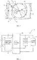
Figure 1 shows a conventional drive circuit for a synchronous motor, which allows a rotor to rotate in a same predetermined direction in every time it starts. In the circuit, astator winding 1 of the motor is connected in series with a TRIAC between two terminals M and N of an AC power source VM, and an AC power source VM is converted by a conversion circuit DC into a direct current voltage and the direct current is supplied to a position sensor H. A magnetic pole position of a rotor in the motor is detected by the position sensor H, and an output signal Vh of the position sensor H is connected to a switch control circuit PC to control the bidirectional thyristor T.Figure 2 shows a waveform of the drive circuit. It can be seen fromFigure 2 that, in the drive circuit, no matter the bidirectional thyristor T is switched on or off, the AC power source supplies power for the conversion circuit DC so that the conversion circuit DC constantly outputs and supplies power for the position sensor H (referring to a signal VH inFigure 2 ). In a low-power application, in a case that the AC power source is commercial electricity of about 200V, the electric energy consumed by two resistors R2 and R3 in the conversion circuit DC is more than the electric energy consumed by the motor. Examples of conventional drive circuits are disclosed inUS6114827 andUS2008/0100255 , for instance. - Hence there is a desire for an improved drive circuit for a permanent magnet motor.
- Accordingly the present invention provides a drive circuit of a permanent magnet motor comprising a stator and a permanent magnet rotor, the stator comprising a stator core and a stator winding wound on the stator core and adapted to be connected in series with an AC power source between a first node and a second node, the drive circuit comprising: a controllable bidirectional AC switch connected between the first node and the second node, the controllable bidirectional AC switch, if switched on, being adapted to remain on in the absence of a drive current; an AC-DC conversion circuit connected in parallel with the controllable bidirectional AC switch between the first node and the second node, wherein there is no current flowing through the AC-DC conversion circuit when the first node and the second node are shorted by the controllable bidirectional AC switch; a position sensor configured to detect a magnetic pole position of the permanent magnet rotor; and characterized by a switch control circuit configured to control the controllable bidirectional AC switch to be switched between a conductive state and a non-conductive state in a predetermined way, based on an output of the position sensor and the polarity of the AC power source such that the stator winding drives the rotor to rotate only in a predetermined direction when the magnetic pole position of the permanent magnet rotor has a first polarity and the AC power source is in a positive half-cycle or when the magnetic pole position of the permanent magnet rotor has a second polarity and the AC power source is in a negative half-cycle, the controllable bidirectional AC switch being switched into the conductive state when a drive current to the controllable bidirectional AC switch exceeds a gate triggering current, and the controllable bidirectional AC switch being switched into the non-conductive state when the drive current falls below the gate triggering current and a current flowing through the controllable bidirectional AC switch is less than a holding current, and wherein there is no current flowing through the AC-DC conversion circuit when the first node and the second node are short circuited by the controllable bidirectional AC switch.
- Preferably, the controllable bidirectional AC switch includes a TRIAC, or may include two silicon control rectifiers reversely connected in parallel.
- Preferably, a first anode of the TRIAC is connected to the first node, a second anode of the TRIAC is connected to the second node, and a control electrode of the TRIAC is connected to the switch control circuit.
- Preferably, the AC-DC conversion circuit comprises a full wave rectifying circuit having a high voltage output terminal and a low voltage output terminal.
- Preferably, a zener diode is connected between the high voltage output terminal and the low voltage output terminal.
- Preferably, the AC-DC conversion circuit comprises a first diode and a second diode which are reversely connected in parallel between the first node and the second node respectively via a first resistor and a second resistor, a high voltage output terminal of the AC-DC conversion circuit is formed at a connection point of the first resistor and a cathode of the first diode, a low voltage output terminal of the AC-DC conversion circuit is formed at a connection point of the second resistor and an anode of the second diode, and the first diode and the second diode are zener diodes.
- Preferably, the AC-DC conversion circuit comprises a first resistor connected in series with the full wave bridge rectifier between the first node and the second node.
- Preferably, the full wave bridge rectifier comprises two rectifier branches connected in parallel, one of the two rectifier branches comprising a first diode and a third diode reversely connected in series, and the other of the two rectifier branches comprises a second diode and a fourth diode reversely connected in series, the high voltage output terminal of the AC-DC conversion circuit is formed at a connection point of a cathode of the first diode and a cathode of the third diode, and the low voltage output terminal of the AC-DC conversion circuit is formed at a connection point of an anode of the second diode and an anode of the fourth diode.
- Preferably, the second diode and the fourth diode are zener diodes.
- Preferably, the full wave bridge rectifier comprises two rectifier branches connected in parallel, one of the two rectifier branches comprises two silicon control rectifiers reversely connected in series, and the other of the two rectifier branches comprises a second diode and a fourth diode reversely connected in series, the high voltage output terminal of the AC-DC conversion circuit is formed at a connection point of cathodes of the two silicon control rectifiers, and the low voltage output terminal of the AC-DC conversion circuit is formed at a connection point of an anode of the second diode and an anode of the fourth diode.
- Preferably, a first signal terminal connects the cathodes of the two silicon control rectifiers and a second signal terminal connects the control terminals of the two silicon control rectifiers, wherein the first signal terminal is connected to a reference voltage; a control signal input from the second signal terminal ensures the two silicon control rectifiers to be switched between a switch-on state and a switch-off state in a predetermined way in a case that the drive circuit operates normally, or a control signal input from the second signal terminal enables the two silicon control rectifiers to be switched off in a case that the drive circuit fails.
- Preferably, the AC-DC conversion circuit has a high voltage output terminal and a low voltage output terminal, the switch control circuit comprises a first terminal connected to the high voltage output terminal, a second terminal connected to an output terminal of the position sensor, and a third terminal connected to the control electrode of the controllable bidirectional AC switch, the high voltage output terminal of the AC-DC conversion circuit is connected to a positive power supply terminal of the position sensor, and a low voltage output terminal of the AC-DC conversion circuit is connected to a negative power supply terminal of the position sensor.
- Preferably, a preset steering circuit is disposed between the third terminal of the switch control circuit and the control electrode of the controllable bidirectional AC switch, and the preset steering circuit comprises a first jumper switch connected between the third terminal and the control electrode of the controllable bidirectional AC switch, and a second jumper switch and an inverter connected in series which are connected in parallel with the first jumper switch between the third terminal and the control electrode.
- Preferably, the switch control circuit further comprises a third resistor, a fourth resistor, and a fifth diode and a sixth diode reversely connected in series between the output terminal of the position sensor and the control electrode of the controllable bidirectional AC switch; a cathode of the fifth diode is connected to the output terminal of the position sensor, and a cathode of the sixth diode is connected to the control electrode of the controllable bidirectional AC switch; one terminal of the third resistor is connected to the high voltage output terminal of the AC-DC conversion circuit, and the other terminal of the third resistor is connected to a connection point of an anode of the fifth diode and an anode of the sixth diode; and two terminals of the fourth resistor are connected to a cathode of the fifth diode and a cathode of the sixth diode respectively.
- Preferably, the switch control circuit further comprises a third resistor, a fifth diode, and a fourth resistor and a sixth diode connected in series between the output terminal of the position sensor and the control electrode of the controllable bidirectional AC switch; an anode of the sixth diode is connected to the control electrode of the controllable bidirectional AC switch; one terminal of the third resistor is connected to the high voltage output terminal of the AC-DC conversion circuit, and the other terminal of the third resistor is connected to a connection point of an anode of the fifth diode and the output terminal of the position sensor; and a cathode of the fifth diode is connected to the control electrode of the controllable bidirectional AC switch.
- Preferably, the switch control circuit further comprises a third resistor, an NPN transistor, and a fourth resistor and a fifth diode connected in series between the output terminal of the position sensor and the control electrode of the controllable bidirectional AC switch; a cathode of the fifth diode is connected to the output terminal of the position sensor; one terminal of the third resistor is connected to the high voltage output terminal of the AC-DC conversion circuit, and the other terminal of the third resistor is connected to the output terminal of the position sensor; and a base of the NPN transistor is connected to the output terminal of the position sensor, an emitter of the NPN transistor is connected to an anode of the fifth diode, and a collector of the NPN transistor is connected to the high voltage output terminal of the AC-DC conversion circuit.
- Preferably, a non-uniform gap is formed between the stator and the permanent magnet rotor, and a polar axis of the permanent magnet rotor has an angular offset relative to a central axis of the stator when the permanent magnet rotor is at rest.
- A preferred embodiment of the invention will now be described, by way of example only, with reference to figures of the accompanying drawings. In the figures, identical structures, elements or parts that appear in more than one figure are generally labeled with a same reference numeral in all the figures in which they appear. Dimensions of components and features shown in the figures are generally chosen for convenience and clarity of presentation and are not necessarily shown to scale. The figures are listed below.
-
Figure 1 shows a prior art drive circuit for a synchronous motor; -
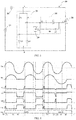
Figure 2 shows a waveform of the drive circuit shown inFigure 1 ; -
Figure 3 is a diagrammatic representation of a synchronous motor according to the present invention; -
Figure 4 is a block diagram of a drive circuit for a synchronous motor according to the present invention; -
Figure 5 shows a drive circuit for a synchronous motor according to an embodiment of the present invention; -
Figure 6 shows a waveform of the drive circuit shown inFigure 5 ; and -
Figures 7 to 10 each show a drive circuit of a synchronous motor according to further embodiments of the present invention. -
Figure 3 schematically shows a synchronous motor according to an embodiment of the present invention. Thesynchronous motor 10 includes astator 12 and apermanent magnet rotor 14 rotatably disposed between magnetic poles of thestator 12, and thestator 12 includes astator core 15 and a stator winding 16 wound on thestator core 15. Therotor 14 includes at least one permanent magnet forming at least one pair of permanent magnetic poles with opposite polarities, and therotor 14 operates at a constant rotational speed of 60f/p during a steady state phase in a case that the stator winding 16 is connected to an AC power supply, where f is a frequency of the AC power supply and p is the number of pole pairs of the rotor. -
Non-uniform gap 18 is formed between the magnetic poles of thestator 12 and the permanent magnetic poles of therotor 14 so that a polar axis R of therotor 14 has an angular offset α relative to a central axis S of thestator 12 in a case that the rotor is at rest. Therotor 14 may be configured to have a fixed starting direction (a clockwise direction in this embodiment as shown by the arrow inFig. 3 ) every time the stator winding 16 is energized. The stator and the rotor each have two magnetic poles as shown inFigure 3 . It can be understood that, in other embodiments, the stator and the rotor may also have more magnetic poles, such as 4 or 6 magnetic poles. - A
position sensor 20 for detecting the angular position of the rotor is disposed on thestator 12 or at a position near the rotor inside the stator, and theposition sensor 20 has an angular offset relative to the central axis S of the stator. Preferably, this angular offset is also α, as in this embodiment. Preferably, theposition sensor 20 is a Hall effect sensor. -
Figure 4 shows a block diagram of a drive circuit for a synchronous motor according to an embodiment of the present invention. In thedrive circuit 22, the stator winding 16 and theAC power supply 24 are connected in series between two nodes A and B. Preferably, theAC power supply 24 may be a commercial AC power supply with a fixed frequency, such as 50Hz or 60Hz, and a supply voltage may be, for example, 110V, 220V or 230V. A controllablebidirectional AC switch 26 is connected between the two nodes A and B, in parallel with the stator winding 16 and theAC power supply 24. Preferably, the controllablebidirectional AC switch 26 is a TRIAC, of which two anodes are connected to the two nodes A and B respectively. It can be understood that, the controllablebidirectional AC switch 26 alternatively may be two silicon control rectifiers reversely connected in parallel, and control circuits may be correspondingly configured to control the two silicon control rectifiers in a preset way. An AC-DC conversion circuit 28 is also connected between the two nodes A and B. An AC voltage between the two nodes A and B is converted by the AC-DC conversion circuit 28 into a low voltage DC. Theposition sensor 20 may be powered by the low voltage DC output by the AC-DC conversion circuit 28, for detecting the magnetic pole position of thepermanent magnet rotor 14 of thesynchronous motor 10 and outputting a corresponding signal. Aswitch control circuit 30 is connected to the AC-DC conversion circuit 28, theposition sensor 20 and the controllablebidirectional AC switch 26, and is configured to control the controllablebidirectional AC switch 26 to be switched between a switch-on state and a switch-off state in a predetermined way, based on the magnetic pole position of the permanent magnet rotor which is detected by the position sensor and polarity information of theAC power supply 24 which may be obtained from the AC-DC conversion circuit 28, such that the stator winding 16 urges therotor 14 to rotate only in the above-mentioned fixed starting direction during a starting phase of the motor. According to this embodiment of the present invention, in a case that the controllablebidirectional AC switch 26 is switched on, the two nodes A and B are shorted, the AC-DC conversion circuit 28 does not consume electric energy since there is no current flowing through the AC-DC conversion circuit 28, hence, the utilization efficiency of electric energy can be improved significantly. -
Figure 5 shows a circuit diagram of adrive circuit 40 for a synchronous motor according to a first embodiment of the present disclosure. The stator winding 16 of the synchronous motor is connected in series with theAC power supply 24 between the two nodes A and B. A first anode T1 of theTRIAC 26 is connected to the node A, and a second anode T2 of theTRIAC 26 is connected to the node B. The AC-DC conversion circuit 28 is connected in parallel with theTRIAC 26 between the two nodes A and B. An AC voltage between the two nodes A and B is converted by the AC-DC conversion circuit 28 into a low voltage DC (preferably, low voltage ranges from 3V to 18V). The AC-DC conversion circuit 28 includes a first zener diode Z1 and a second zener diode Z2 which are reversely connected in parallel between the two nodes A and B via a first resistor R1 and a second resistor R2 respectively. A high voltage output terminal C of the AC-DC conversion circuit 28 is formed at a connection point of the first resistor R1 and a cathode of the first zener diode Z1, and a low voltage output terminal D of the AC-DC conversion circuit 28 is formed at a connection point of the second resistor R2 and an anode of the second zener diode Z2. The voltage output terminal C is connected to a positive power supply terminal of theposition sensor 20, and the voltage output terminal D is connected to a negative power supply terminal of theposition sensor 20. Three terminals of theswitch control circuit 30 are connected to the high voltage output terminal C of the AC-DC conversion circuit 28, an output terminal HI of theposition sensor 20 and a control electrode G of theTRIAC 26 respectively. Theswitch control circuit 30 includes a third resistor R3, a fifth diode D5, and a fourth resistor R4 and a sixth diode D6 connected in series between the output terminal HI of theposition sensor 20 and the control electrode G of the controllablebidirectional AC switch 26. An anode of the sixth diode D6 is connected to the control electrode G of the controllablebidirectional AC switch 26. One terminal of the third resistor R3 is connected to the high voltage output terminal C of the AC-DC conversion circuit 28, and the other terminal of the third resistor R3 is connected to an anode of the fifth diode D5. A cathode of the fifth diode D5 is connected to the control electrode G of the controllablebidirectional AC switch 26. - In conjunction with
Figure 6 , an operational principle of thedrive circuit 40 is described. InFigure 6 , Vac indicates a waveform of voltage of theAC power supply 24, and lac indicates a waveform of current flowing through the stator winding 16. Due to the inductive character of the stator winding 16, the waveform of current lac lags behind the waveform of voltage Vac. VI indicates a waveform of voltage between two terminals of the first zener diode Z1, V2 indicates a waveform of voltage between two terminals of the second zener diode Z2, Vdc indicates a waveform of voltage between two output terminals C and D of the AC-DC conversion circuit 28, Ha indicates a waveform of a signal output by the output terminal HI of theposition sensor 20, and Hb indicates a rotor magnetic field detected by theposition sensor 20. In this embodiment, in a case that theposition sensor 20 is powered normally, the output terminal HI outputs a logic high level in a case that the detected rotor magnetic field is North, or the output terminal HI outputs a logic low level in a case that the detected rotor magnetic field is South. - In a case that the rotor magnetic field Hb detected by the
position sensor 20 is North, in a first positive half cycle of the AC power supply, the supply voltage is gradually increased from a time instant t0 to a time instant t1, the output terminal HI of theposition sensor 20 outputs a high level, and a current flows through the resistor R1, the resistor R3, the diode D5 and the control electrode G and the second anode T2 of theTRIAC 26 sequentially. TheTRIAC 26 is switched on in a case that a drive current flowing through the control electrode G and the second anode T2 is greater than a gate triggering current Ig. Once theTRIAC 26 is switched on, the two nodes A and B are shorted, a current flowing through the stator winding 16 in the motor is gradually increased until a large forward current flows through the stator winding 16 to drive therotor 14 to rotate clockwise as shown inFigure 3 . Since the two nodes A and B are shorted, there is no current flowing through the AC-DC conversion circuit 28 from the time instant t1 to a time instant t2. Hence, the resistors R1 and R2 do not consume electric energy, and the output of theposition sensor 20 is stopped due to no power is supplied. Since the current flowing through two anodes T1 and T2 of theTRIAC 26 is large enough (which is greater than a holding current Ihold), theTRIAC 26 is kept to be switched on in a case that there is no drive current flowing through the control electrode G and the second anode T2. In a negative half cycle of the AC power supply, after a time instant t3, a current flowing through T1 and T2 is less than the holding current Ihold, theTRIAC 26 is switched off, a current begins to flow through the AC-DC conversion circuit 28, and the output terminal HI of theposition sensor 20 outputs a high level again. Since a potential at the point C is lower than a potential at the point E, there is no drive current flowing through the control electrode G and the second anode T2 of theTRIAC 26, and theTRIAC 26 is kept to be switched off. Since the resistance of the resistors R1 and R2 in the AC-DC conversion circuit 28 are far greater than the resistance of the stator winding 16 in the motor, a current currently flowing through the stator winding 16 is far less than the current flowing through the stator winding 16 from the time instant t1 to the time instant t2 and generates very small driving force for therotor 14. Hence, therotor 14 continues to rotate clockwise due to inertia. In a second positive half cycle of the AC power supply, similar to the first positive half cycle, a current flows through the resistor R1, the resistor R3, the diode D5, and the control electrode G and the second anode T2 of theTRIAC 26 sequentially. TheTRIAC 26 is switched on again, and the current flowing through the stator winding 16 continues to drive therotor 14 to rotate clockwise. Similarly, the resistors R1 and R2 do not consume electric energy since the two nodes A and B are shorted. In the next negative half cycle of the power supply, the current flowing through the two anodes T1 and T2 of theTRIAC 26 is less than the holding current Ihold, theTRIAC 26 is switched off again, and the rotor continues to rotate clockwise due to the effect of inertia. - At a time instant t4, the rotor magnetic field Hb detected by the
position sensor 20 changes to be South from North, the AC power supply is still in the positive half cycle and theTRIAC 26 is switched on, the two nodes A and B are shorted, and there is no current flowing through the AC-DC conversion circuit 28. After the AC power supply enters the negative half cycle, the current flowing through the two anodes T1 and T2 of theTRIAC 26 is gradually decreased, and theTRIAC 26 is switched off at a time instant t5. Then the current flows through the second anode T2 and the control electrode G of theTRIAC 26, the diode D6, the resistor R4, theposition sensor 20, the resistor R2 and the stator winding 16 sequentially. As the drive current is gradually increased, theTRIAC 26 is switched on again at a time instant t6, the two nodes A and B are shorted again, the resistors R1 and R2 do not consume electric energy, and the output of theposition sensor 20 is stopped due to no power is supplied. There is a larger reverse current flowing through the stator winding 16, and therotor 14 continues to be driven clockwise since the rotor magnetic field is South. From the time instant t5 to the time instant t6, the first zener diode Z1 and the second zener diode Z2 are switched on, hence, there is a voltage output between the two output terminals C and D of the AC-DC conversion circuit 28. At a time instant t7, the AC power supply enters the positive half cycle again, theTRIAC 26 is switched off when the current flowing through theTRIAC 26 crosses zero, and then a voltage of the control circuit is gradually increased. As the voltage is gradually increased, a current begins to flow through the AC-DC conversion circuit 28, the output terminal HI of theposition sensor 20 outputs a low level, there is no drive current flowing through the control electrode G and the second anode T2 of theTRIAC 26, hence, theTRIAC 26 is switched off. Since the current flowing through the stator winding 16 is very small, nearly no driving force is generated for therotor 14. At a time instant t8, the power supply is in the positive half cycle, the position sensor outputs a low level, theTRIAC 26 is kept to be switched off after the current crosses zero, and the rotor continues to rotate clockwise due to inertia. According to an embodiment of the present invention, the rotor may be accelerated to be synchronized with the stator after rotating only one circle after the stator winding is energized. - In the embodiment of the present invention, by taking advantage of a feature of a TRIAC that the TRIAC is kept to be switched on although there is no drive current flowing though the TRIAC once the TRIAC is switched on, it is avoided that a resistor in the AC-DC conversion circuit still consumes electric energy after the TRIAC is switched on, hence, the utilization efficiency of electric energy can be improved significantly.
-
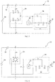
Figure 7 shows a circuit diagram of adrive circuit 42 for a synchronous motor according to an embodiment of the present disclosure. The stator winding 16 of the synchronous motor is connected in series with theAC power supply 24 between the two nodes A and B. A first anode T1 of theTRIAC 26 is connected to the node A, and a second anode T2 of theTRIAC 26 is connected to the node B. The AC-DC conversion circuit 28 is connected in parallel with theTRIAC 26 between the two nodes A and B. An AC between the two nodes A and B is converted by the AC-DC conversion circuit 28 into a low voltage DC, preferably, a low voltage ranging from 3V to 18V. The AC-DC conversion circuit 28 includes a first resistor R1 and a full wave bridge rectifier connected in series between the two nodes A and B. The full wave bridge rectifier includes two rectifier branches connected in parallel, one of the two rectifier branches includes a first diode D1 and a third diode D3 reversely connected in series, and the other of the two rectifier branches includes a second zener diode Z2 and a fourth zener diode Z4 reversely connected in series, the high voltage output terminal C of the AC-DC conversion circuit 28 is formed at a connection point of a cathode of the first diode D1 and a cathode of the third diode D3, and the low voltage output terminal D of the AC-DC conversion circuit 28 is formed at a connection point of an anode of the second zener diode Z2 and an anode of the fourth zener diode Z4. The output terminal C is connected to a positive power supply terminal of theposition sensor 20, and the output terminal D is connected to a negative power supply terminal of theposition sensor 20. Theswitch control circuit 30 includes a third resistor R3, a fourth resistor R4, and a fifth diode D5 and a sixth diode D6 reversely connected in series between the output terminal HI of theposition sensor 20 and the control electrode G of the controllablebidirectional AC switch 26. A cathode of the fifth diode D5 is connected to the output terminal HI of the position sensor, and a cathode of the sixth diode D6 is connected to the control electrode G of the controllable bidirectional AC switch. One terminal of the third resistor R3 is connected to the high voltage output terminal C of the AC-DC conversion circuit, and the other terminal of the third resistor R3 is connected to a connection point of an anode of the fifth diode D5 and an anode of the sixth diode D6. Two terminals of the fourth resistor R4 are connected to a cathode of the fifth diode D5 and a cathode of the sixth diode D6 respectively. -
Figure 8 shows a circuit diagram of adrive circuit 44 for a synchronous motor according to a further embodiment of the present invention. Thedrive circuit 44 is similar to thedrive circuit 42 in the previous embodiment and, thedrive circuit 44 differs from thedrive circuit 42 in that, the zener diodes Z2 and Z4 in thedrive circuit 42 are replaced by general diodes D2 and D4 in the rectifier of thedrive circuit 44. In addition, a zener diode Z7 is connected between the two output terminals C and D of the AC-DC conversion circuit 28 in thedrive circuit 44. -
Figure 9 shows a circuit diagram of adrive circuit 46 for a synchronous motor according to further embodiment of the present invention. The stator winding 16 of the synchronous motor is connected in series with theAC power supply 24 between the two nodes A and B. A first anode T1 of theTRIAC 26 is connected to the node A, and a second anode T2 of theTRIAC 26 is connected to the node B. The AC-DC conversion circuit 28 is connected in parallel with theTRIAC 26 between the two nodes A and B. An AC voltage between the two nodes A and B is converted by the AC-DC conversion circuit 28 into a low voltage DC, preferably, a low voltage ranging from 3V to 18V. The AC-DC conversion circuit 28 includes a first resistor R1 and a full wave bridge rectifier connected in series between the two nodes A and B. The full wave bridge rectifier includes two rectifier branches connected in parallel, one of the two rectifier branches includes two silicon control rectifiers S1 and S3 reversely connected in series, and the other of the two rectifier branches includes a second diode D2 and a fourth diode D4 reversely connected in series. The high voltage output terminal C of the AC-DC conversion circuit 28 is formed at a connection point of a cathode of the silicon control rectifier S1 and a cathode of the silicon control rectifier S3, and the low voltage output terminal D of the AC-DC conversion circuit 28 is formed at a connection point of an anode of the second diode D2 and an anode of the fourth diode D4. The output terminal C is connected to a positive power supply terminal of theposition sensor 20, and the output terminal D is connected to a negative power supply terminal of theposition sensor 20. Theswitch control circuit 30 includes a third resistor R3, an NPN transistor T6, and a fourth resistor R4 and a fifth diode D5 connected in series between the output terminal HI of theposition sensor 20 and the control electrode G of the controllablebidirectional AC switch 26. A cathode of the fifth diode D5 is connected to the output terminal HI of the position sensor. One terminal of the third resistor R3 is connected to the high voltage output terminal C of the AC-DC conversion circuit, and the other terminal of the third resistor R3 is connected to the output terminal HI of the position sensor. A base of the NPN transistor T6 is connected to the output terminal HI of the position sensor, an emitter of the NPN transistor T6 is connected to an anode of the fifth diode D5, and a collector of the NPN transistor T6 is connected to the high voltage output terminal C of the AC-DC conversion circuit. - In this embodiment, a reference voltage may be input to the cathodes of the two silicon control rectifiers S1 and S3 via a terminal SC1, and a control signal may be input to control terminals of S1 and S3 via a terminal SC2. The rectifiers S1 and S3 are switched on in a case that the control signal input from the terminal SC2 is a high level, or are switched off in a case that the control signal input from the terminal SC2 is a low level. Based on the configuration, the rectifiers S1 and S3 may be switched between a switch-on state and a switch-off state in a preset way by inputting the high level from the terminal SC2 in a case that the drive circuit operates normally. The rectifiers S1 and S3 are switched off by changing the control signal input from the terminal SC2 from the high level to the low level in a case that the drive circuit fails. In this case, the
TRIAC 26, theconversion circuit 28 and theposition sensor 20 are switched off, to ensure the whole circuit to be in a zero-power state. -
Figure 10 shows a circuit diagram of adrive circuit 48 for a synchronous motor according to another embodiment of the present invention. Thedrive circuit 48 is similar to thedrive circuit 46 in the previous embodiment and, thedrive circuit 48 differs from thedrive circuit 46 in that, the silicon control diodes S1 and S3 in thedrive circuit 46 are replaced by general diodes D1 and D3 in the rectifier of thedrive circuit 48, and a zener diode Z7 is connected between the two terminals C and D of the AC-DC conversion circuit 28. In addition, in thedrive circuit 48 according to the embodiment, apreset steering circuit 50 is disposed between theswitch control circuit 30 and theTRIAC 26. Thepreset steering circuit 50 includes a first jumper switch J1, a second jumper J2 switch and an inverter NG connected in series with the second jumper switch J2. Similar to thedrive circuit 46, in this embodiment, theswitch control circuit 30 includes the resistor R3, the resistor R4, the NPN transistor T5 and the diode D6. One terminal of the resistor R4 is connected to a connection point of an emitter of the transistor T5 and an anode of the diode D6, and the other terminal of the resistor R4 is connected to one terminal of the first jumper switch J1, and the other terminal of the first jumper switch J1 is connected to the control electrode G of theTRIAC 26, and the second jumper switch J2 and the inverter NG connected in series are connected across two terminals of the first jumper switch J1. In this embodiment, when the first jumper switch J1 is switched on and the second jumper switch J2 is switched off, similar to the above embodiments, therotor 14 still starts clockwise; when the second jumper switch J2 is switched on and the first jumper switch J1 is switched off, therotor 14 starts counterclockwise. In this case, a starting direction of the rotor in the motor may be selected by selecting one of the two jumper switches to be switched on and the other to be switched off. Therefore, in a case that a driving motor is needed to be supplied for different applications having opposite rotational directions, it is just needed to select one of the two jumper switches J1 and J2 to be switched on and the other to be switched off, and no other changes need to be made to the drive circuit, hence, the drive circuit according to this embodiment has good versatility. - In the description and claims of the present application, each of the verbs "comprise", "include", "contain" and "have", and variations thereof, are used in an inclusive sense, to specify the presence of the stated item or feature but do not preclude the presence of additional items or features.
- It is appreciated that certain features of the invention, which are, for clarity, described in the context of separate embodiments, may also be provided in combination in a single embodiment. Conversely, various features of the invention which are, for brevity, described in the context of a single embodiment, may also be provided separately or in any suitable sub-combination.
- The embodiments described above are provided by way of example only, and various other modifications will be apparent to persons skilled in the field without departing from the scope of the invention as defined by the appended claims.
- For example, the drive circuit according to the embodiments of the present invention not only is applied to the synchronous motor, but also is applied to other types of permanent magnetic motors such as a brushless DC motor.
Claims (15)
- A drive circuit of a permanent magnet motor comprising a stator (12) and a permanent magnet rotor (14), the stator comprising a stator core (15) and a stator winding (16) wound on the stator core and adapted to be connected in series with an AC power source (24) between a first node (A) and a second node (B), the drive circuit comprising:a controllable bidirectional AC switch (26) connected between the first node (A) and the second node (B), the controllable bidirectional AC switch (26), if switched on, being adapted to remain on in the absence of a drive current;an AC-DC conversion circuit (28) connected in parallel with the controllable bidirectional AC switch between the first node and the second node;a position sensor (20) configured to detect a magnetic pole position of the permanent magnet rotor; andcharacterized by a switch control circuit (30) configured to control the controllable bidirectional AC switch to be switched between a conductive state and a non-conductive state in a predetermined way, based on an output of the position sensor (20) and the polarity of the AC power source such that the stator winding drives the rotor to rotate only in a predetermined direction when the magnetic pole position of the permanent magnet rotor has a first polarity and the AC power source is in a positive half-cycle or when the magnetic pole position of the permanent magnet rotor has a second polarity and the AC power source is in a negative half-cycle,the controllable bidirectional AC switch being switched into the conductive state when a drive current to the controllable bidirectional AC switch exceeds a gate triggering current (Ig), and the controllable bidirectional AC switch being switched into the non-conductive state when the drive current falls below the gate triggering current (Ig) and a current flowing through the controllable bidirectional AC switch is less than a holding current (Ihold), andwherein there is no current flowing through the AC-DC conversion circuit (28) when the first node (A) and the second node (B) are short circuited by the controllable bidirectional AC switch (26).
- A drive circuit according to Claim 1, wherein the controllable bidirectional AC switch (26) includes a TRIAC, and a first anode (T1) of the TRIAC is connected to the first node (A), a second anode (T2) of the TRIAC is connected to the second node (B), and a control electrode (G) of the TRIAC is connected to the switch control circuit (30), or wherein the controllable bidirectional AC switch (26) includes two silicon control rectifiers reversely connected in parallel.
- A drive circuit according to Claim 2, wherein the AC-DC conversion circuit(28) comprises a full wave rectifying circuit having a high voltage output terminal (C) and a low voltage output terminal (D), and
a zener diode (Z7) is connected between the high voltage output terminal (C) and the low voltage output terminal (D). - A drive circuit according to Claim 2, wherein the AC-DC conversion circuit (28) comprises a first diode (Z1) and a second diode (Z2) which are reversely connected in parallel between the first node (A) and the second node (B) via a first resistor (R1) and a second resistor (R2) respectively, a high voltage output terminal (C) of the AC-DC conversion circuit is formed at a connection point of the first resistor and a cathode of the first diode, a low voltage output terminal (D) of the AC-DC conversion circuit is formed at a connection point of the second resistor and an anode of the second diode, and the first diode and the second diode are zener diodes.
- A drive circuit according to Claim 2, wherein the AC-DC conversion circuit(28) comprises a full wave rectifying circuit having a high voltage output terminal (C) and a low voltage output terminal (D), and
the AC-DC conversion circuit (28) comprises a first resistor (R1) connected in series with the full wave bridge rectifier between the first node (A) and the second node (B). - A drive circuit according to Claim 2, wherein the AC-DC conversion circuit(28) comprises a full wave rectifying circuit having a high voltage output terminal (C) and a low voltage output terminal (D), and
the full wave bridge rectifier comprises two rectifier branches connected in parallel, one of the two rectifier branches comprising a first diode (D1) and a third diode (D3) reversely connected in series, and the other of the two rectifier branches comprises a second diode (D2) and a fourth diode (D4) reversely connected in series, the high voltage output terminal (C) of the AC-DC conversion circuit is formed at a connection point of a cathode of the first diode and a cathode of the third diode, and the low voltage output terminal (D) of the AC-DC conversion circuit is formed at a connection point of an anode of the second diode and an anode of the fourth diode. - A drive circuit according to Claim 6, wherein the second diode (D2) and the fourth diode (D4) are zener diodes.
- A drive circuit according to Claim 2, wherein the AC-DC conversion circuit(28) comprises a full wave rectifying circuit having a high voltage output terminal (C) and a low voltage output terminal (D), and
the full wave bridge rectifier comprises two rectifier branches connected in parallel, one of the two rectifier branches comprises two silicon control rectifiers (S1, S3) reversely connected in series, and the other of the two rectifier branches comprises a second diode (D2) and a fourth diode (D4) reversely connected in series, the high voltage output terminal (C) of the AC-DC conversion circuit is formed at a connection point of cathodes of the two silicon control rectifiers, and the low voltage output terminal (D) of the AC-DC conversion circuit is formed at a connection point of an anode of the second diode and an anode of the fourth diode. - A drive circuit according to Claim 8, further comprising: a first signal terminal (SC1) connected to cathodes of the two silicon control rectifiers and a second signal terminal (SC2) connected to control terminals of the two silicon control rectifiers (S1, S2), wherein the first signal terminal is connected to a reference voltage; a control signal input from the second signal terminal ensures the two silicon control rectifiers to be switched between a switch-on state and a switch-off state in a predetermined way in a case that the drive circuit operates normally, or a control signal input from the second signal terminal enables the two silicon control rectifiers to be switched off in a case that the drive circuit fails.
- A drive circuit according to Claim 1, or 2, wherein the AC-DC conversion circuit (28) has a high voltage output terminal (C) and a low voltage output terminal (D), the switch control circuit (30) comprises a first terminal connected to the high voltage output terminal, a second terminal connected to an output terminal of the position sensor (20), and a third terminal connected to the control electrode (G) of the controllable bidirectional AC switch (26), the high voltage output terminal of the AC-DC conversion circuit is connected to a positive power supply terminal of the position sensor (20), and the low voltage output terminal of the AC-DC conversion circuit is connected to a negative power supply terminal of the position sensor.
- A drive circuit according to Claim 10, wherein a preset steering circuit (50) is disposed between the third terminal of the switch control circuit (30) and the control electrode (G) of the controllable bidirectional AC switch (26), and the preset steering circuit comprises a first jumper switch (J1) connected between the third terminal and the control electrode of the controllable bidirectional AC switch, and a second jumper switch (J2) and an inverter (NG) connected in series which are connected in parallel with the first jumper switch between the third terminal and the control electrode (G).
- A drive circuit according to Claim 10, wherein the switch control circuit (30) further comprises a third resistor (R3), a fourth resistor (R4), and a fifth diode (D5) and a sixth diode (D6) reversely connected in series between the output terminal of the position sensor (20) and the control electrode (G) of the controllable bidirectional AC switch (26); a cathode of the fifth diode is connected to the output terminal of the position sensor, and a cathode of the sixth diode is connected to the control electrode of the controllable bidirectional AC switch; one terminal of the third resistor is connected to the high voltage output terminal (C) of the AC-DC conversion circuit (28), and the other terminal of the third resistor is connected to a connection point of an anode of the fifth diode and an anode of the sixth diode; and two terminals of the fourth resistor are connected to a cathode of the fifth diode and a cathode of the sixth diode respectively.
- A drive circuit according to Claim 10, wherein the switch control circuit (30) further comprises a third resistor (R3), a fifth diode (D5), and a fourth resistor (R4) and a sixth diode (D6) connected in series between the output terminal of the position sensor (20) and the control electrode (G) of the controllable bidirectional AC switch (26); an anode of the sixth diode is connected to the control electrode of the controllable bidirectional AC switch; one terminal of the third resistor is connected to the high voltage output terminal (C) of the AC-DC conversion circuit (28), and the other terminal of the third resistor is connected to a connection point of an anode of the fifth diode and the output terminal of the position sensor; and a cathode of the fifth diode is connected to the control electrode (G) of the controllable bidirectional AC switch (26).
- A drive circuit according to Claim 10, wherein the switch control circuit (30) further comprises a third resistor (R3), an NPN transistor (T6), and a fourth resistor (R4) and a fifth diode (D5) connected in series between the output terminal of the position sensor (20) and the control electrode (G) of the controllable bidirectional AC switch (26); a cathode of the fifth diode is connected to the output terminal of the position sensor; one terminal of the third resistor is connected to the high voltage output terminal (C) of the AC-DC conversion circuit (28), and the other terminal of the third resistor is connected to the output terminal of the position sensor; and a base of the NPN transistor (T6) is connected to the output terminal of the position sensor, an emitter of the NPN transistor is connected to an anode of the fifth diode, and a collector of the NPN transistor is connected to the high voltage output terminal of the AC-DC conversion circuit.
- A drive circuit according to any one of Claims 1 to 14, wherein a non-uniform gap (18) is formed between the stator (12) and the permanent magnet rotor (14), and a polar axis (R) of the permanent magnet rotor has an angular offset (α) relative to a central axis (S) of the stator when the permanent magnet rotor is at rest.
Applications Claiming Priority (2)
| Application Number | Priority Date | Filing Date | Title |
|---|---|---|---|
| CN201410390592 | 2014-08-08 | ||
| CN201410404474.2A CN107634683B (en) | 2014-08-08 | 2014-08-15 | Synchronous motor drive circuit |
Publications (2)
| Publication Number | Publication Date |
|---|---|
| EP2983288A1 EP2983288A1 (en) | 2016-02-10 |
| EP2983288B1 true EP2983288B1 (en) | 2021-07-28 |
Family
ID=53783646
Family Applications (1)
| Application Number | Title | Priority Date | Filing Date |
|---|---|---|---|
| EP15180248.5A Active EP2983288B1 (en) | 2014-08-08 | 2015-08-07 | Drive circuit for a permanent magnet motor |
Country Status (10)
| Country | Link |
|---|---|
| US (4) | US9755555B2 (en) |
| EP (1) | EP2983288B1 (en) |
| JP (14) | JP2017529057A (en) |
| KR (3) | KR20170039728A (en) |
| CN (17) | CN107306517B (en) |
| BR (1) | BR102015019000B1 (en) |
| DE (2) | DE112015003682T5 (en) |
| MX (3) | MX2017001792A (en) |
| TW (6) | TWM547783U (en) |
| WO (2) | WO2016019922A1 (en) |
Families Citing this family (20)
| Publication number | Priority date | Publication date | Assignee | Title |
|---|---|---|---|---|
| MX2017001792A (en) * | 2014-08-08 | 2017-04-27 | Johnson Electric Sa | Motor assembly and integrated circuit for motor drive. |
| EP3135937A1 (en) * | 2015-08-14 | 2017-03-01 | Johnson Electric S.A. | Electric apparatus, actuator and clutch thereof |
| CN106469958A (en) * | 2015-08-14 | 2017-03-01 | 德昌电机(深圳)有限公司 | Fluid generating device |
| CN107231062A (en) * | 2016-03-24 | 2017-10-03 | 德昌电机(深圳)有限公司 | The wind cooling refrigerator of cooling fan and the application cooling fan |
| DE102017106426A1 (en) * | 2016-03-28 | 2017-09-28 | Johnson Electric S.A. | Motor, stand and method for forming the stator |
| DE102016118501A1 (en) | 2016-09-29 | 2018-03-29 | Miele & Cie. Kg | Two-strand single-phase synchronous drive |
| JP6892930B2 (en) * | 2017-03-29 | 2021-06-23 | キューエム・パワー・インコーポレイテッドQm Power,Inc | Multi-stage speed AC motor |
| CN108696057B (en) * | 2017-04-12 | 2021-06-25 | 德昌电机(深圳)有限公司 | Motor and electric equipment with same |
| CN109672373A (en) * | 2017-08-25 | 2019-04-23 | 德昌电机(深圳)有限公司 | Motor and its driving circuit and driving method |
| CN109687780A (en) | 2017-08-25 | 2019-04-26 | 德昌电机(深圳)有限公司 | Motor and its driving circuit and driving method |
| CN109842330B (en) * | 2017-11-24 | 2021-12-14 | 南京德朔实业有限公司 | Control method of single-phase brushless motor |
| DE102017223061A1 (en) * | 2017-12-18 | 2019-06-19 | Bühler Motor GmbH | COMMUTATOR ENGINE AND SERIES OF COMMUTATOR MOTORS |
| JP7061457B2 (en) | 2017-12-22 | 2022-04-28 | ローム株式会社 | Magnetic sensors, semiconductor devices and electrical equipment |
| CN111226626B (en) * | 2018-11-28 | 2022-09-16 | 南京泉峰科技有限公司 | Chain saw, electric tool, and control method for electric tool |
| CN109921770A (en) * | 2019-03-07 | 2019-06-21 | 维沃移动通信有限公司 | A kind of motor drive circuit and terminal device |
| JP2023522529A (en) * | 2020-04-25 | 2023-05-31 | 121352 カナダ インコーポレイテッド | Electric motor and its control method |
| IT202000016672A1 (en) * | 2020-07-09 | 2022-01-09 | De Longhi Appliances Srl | METHOD AND CONTROL CIRCUIT FOR A DIRECT CURRENT MOTOR |
| CN111856337A (en) * | 2020-07-10 | 2020-10-30 | 海信集团有限公司 | Control circuit, control panel, electric equipment and control method |
| US11424709B2 (en) * | 2020-11-05 | 2022-08-23 | Raptor Lift Solutions, Llc | Method and apparatus for riding through power disruptions of a drive circuit |
| CN114485738B (en) * | 2022-01-06 | 2024-01-12 | 天津中德应用技术大学 | Double-group Hall sensor device and control method thereof |
Family Cites Families (52)
| Publication number | Priority date | Publication date | Assignee | Title |
|---|---|---|---|---|
| US3056896A (en) * | 1958-11-10 | 1962-10-02 | Licentia Gmbh | Stator for a.c. motor |
| US3596159A (en) * | 1968-03-22 | 1971-07-27 | Janome Sewing Machine Co Ltd | Speed control circuit for a single-phase motor,using a thyristor |
| JPS48102222A (en) * | 1972-04-12 | 1973-12-22 | ||
| DE2407601C2 (en) * | 1974-02-16 | 1980-04-17 | Robert Bosch Gmbh, 7000 Stuttgart | Control device for lowering the speed of an AC-fed series motor in idle mode |
| US4896105A (en) * | 1988-03-25 | 1990-01-23 | Westinghouse Electric Corp. | AC electric energy meter having drive circuit including stepper motor for driving mechanical register |
| US4949214A (en) * | 1989-08-28 | 1990-08-14 | Spencer George A | Trip delay override for electrical circuit breakers |
| US6348752B1 (en) * | 1992-04-06 | 2002-02-19 | General Electric Company | Integral motor and control |
| US5682459A (en) * | 1995-07-27 | 1997-10-28 | Wilkerson; Alan W. | Speed control for controlling the speed of a DC motor |
| US5675226A (en) * | 1995-09-06 | 1997-10-07 | C.E.Set. S.R.L. | Control circuit for an synchronous electric motor of the brushless type |
| JP3555297B2 (en) * | 1996-02-06 | 2004-08-18 | 松下電器産業株式会社 | Power generator and vacuum cleaner as its application equipment |
| US6118427A (en) * | 1996-04-18 | 2000-09-12 | Silicon Graphics, Inc. | Graphical user interface with optimal transparency thresholds for maximizing user performance and system efficiency |
| US6097127A (en) * | 1996-08-22 | 2000-08-01 | Rivera; Nicholas N. | Permanent magnet direct current (PMDC) machine with integral reconfigurable winding control |
| JPH1084685A (en) * | 1996-09-06 | 1998-03-31 | Tominaga Jushi Kogyosho:Kk | Controller for rotational direction of two-pole ac motor |
| JPH10117495A (en) * | 1996-10-09 | 1998-05-06 | Higashifuji Manuf Ltd | Reversible motor |
| IT1289817B1 (en) * | 1996-12-30 | 1998-10-16 | Plaset Srl | DEVICE FOR CONTROL OF A SYNCHRONOUS ELECTRIC MOTOR WITH PERMANENT MAGNET ROTOR |
| JPH10337065A (en) * | 1997-06-03 | 1998-12-18 | Techno Takatsuki:Kk | Synchronous motor |
| JP3446692B2 (en) * | 1999-11-24 | 2003-09-16 | 三菱電機株式会社 | Control device for single-phase motor, actuator and blower using control device for single-phase motor |
| KR100367478B1 (en) * | 2000-12-15 | 2003-01-10 | 김준 | Fabrication Method of Stator Assembly Using Slotless Stator Core on Brushless DC Motor and Brushless DC Motor Thereby |
| DE10103845B4 (en) * | 2001-01-30 | 2006-11-16 | Ontoprise Gmbh | computer system |
| EP1351375B1 (en) * | 2002-03-05 | 2004-09-01 | Askoll Holding S.r.l. | Permanent-magnet synchronous motor with an electronic device for starting the motor and with sensor means which position is dependent on the load driven by the motor |
| US6767817B2 (en) * | 2002-07-11 | 2004-07-27 | Micron Technology, Inc. | Asymmetric plating |
| JP4053840B2 (en) * | 2002-08-26 | 2008-02-27 | 富士通株式会社 | Semiconductor integrated circuit |
| JP2004153906A (en) * | 2002-10-29 | 2004-05-27 | Asahi Kasei Microsystems Kk | Device for preventing reverse connection |
| CN2622928Y (en) * | 2003-05-08 | 2004-06-30 | 建准电机工业股份有限公司 | Speed control circuit of d.c. brushless fan motor |
| ITMI20031661A1 (en) * | 2003-08-22 | 2005-02-23 | Askoll Holding Srl | ELECTRONIC IGNITION AND SHUTDOWN DEVICE FOR |
| JP2005245167A (en) * | 2004-02-27 | 2005-09-08 | Matsushita Electric Ind Co Ltd | Dc power supply unit |
| US7208907B2 (en) * | 2004-10-21 | 2007-04-24 | Shop Vac Corporation | System and method of restarting a switched reluctance motor after a rapid cycling of power |
| JP4691376B2 (en) * | 2005-03-25 | 2011-06-01 | 山洋電気株式会社 | Permanent magnet type rotary motor |
| US20070103103A1 (en) * | 2005-11-09 | 2007-05-10 | Maue H W | Bi-directional motor voltage conversion circuit |
| US7173388B1 (en) * | 2005-11-14 | 2007-02-06 | Power Logic Tech. Inc. | Drive control device for brushless motor |
| US7536860B2 (en) * | 2006-05-25 | 2009-05-26 | Thermotion Corporation | Thermo-magnetic actuator |
| US7622876B2 (en) * | 2006-07-31 | 2009-11-24 | Danaher Motion, Llc | Overload prevention device for permanent magnet DC motors |
| NZ549662A (en) * | 2006-09-04 | 2009-01-31 | Wellington Drive Technologies | Control of synchronous electrical machines |
| CN101174804A (en) * | 2006-10-31 | 2008-05-07 | 德昌电机股份有限公司 | Electric start controlling equipment for synchronous motor |
| DE102006055482A1 (en) | 2006-11-24 | 2008-06-12 | Hanning Elektro-Werke Gmbh & Co. Kg | Method for electronic control of synchronous motor, particularly single phase synchronous motor with permanent magnetic rotor, involves energizing permanent magnetic rotor by alternating voltage switch |
| JP5150276B2 (en) * | 2008-01-25 | 2013-02-20 | パナソニック株式会社 | Insulator structure of motor |
| US7791232B2 (en) * | 2008-05-02 | 2010-09-07 | Black & Decker Inc. | Power tool having an electronically commutated motor and double insulation |
| CN101662205B (en) * | 2008-08-27 | 2013-07-10 | 德昌电机(深圳)有限公司 | Boost-buck accelerating circuit |
| JP4823294B2 (en) * | 2008-11-04 | 2011-11-24 | 三菱電機株式会社 | Blower and heat pump device using this blower |
| CN201409107Y (en) * | 2009-03-12 | 2010-02-17 | 敬石桥 | AC motor control circuit and AC synchronous water pump |
| GB0908111D0 (en) * | 2009-05-12 | 2009-06-24 | Peto Raymond J | A motor controller & related method |
| CN201590796U (en) * | 2009-11-18 | 2010-09-22 | 佛山市顺德区泛仕达机电有限公司 | Driving circuit of single-phase permanent magnet synchronous motor |
| US8618751B2 (en) * | 2009-12-30 | 2013-12-31 | Leviton Manufacturing Co., Inc. | Phase control with adaptive parameters |
| CN102075130B (en) * | 2010-01-21 | 2013-09-25 | 艾如菊 | Convenient method for controlling direction of rotation of synchronous motor of single-phase permanent magnet and motor using same |
| EP2410653B1 (en) * | 2010-07-23 | 2019-04-24 | Askoll Holding S.r.l. | Device for controlling a synchronous electric motor with a permanent magnet rotor |
| TWI553998B (en) * | 2012-07-06 | 2016-10-11 | 緯創資通股份有限公司 | Dynamic charge device and dynamic charge method |
| GB201304269D0 (en) * | 2013-03-08 | 2013-04-24 | Dyson Technology Ltd | Drive circuit for a brushless motor |
| CN103281019B (en) * | 2013-05-29 | 2015-06-03 | 东南大学 | Permanent magnet synchronous motor fault-tolerant-type traction module and control method thereof |
| US20160352267A1 (en) * | 2014-08-08 | 2016-12-01 | Johnson Electric S.A. | Motor driving circuit and motor component |
| MX2017001792A (en) * | 2014-08-08 | 2017-04-27 | Johnson Electric Sa | Motor assembly and integrated circuit for motor drive. |
| CN204993125U (en) * | 2015-08-07 | 2016-01-20 | 德昌电机(深圳)有限公司 | Motor element , integrated circuit who is used for motor drive , fan and pump |
| CN205984965U (en) * | 2015-08-07 | 2017-02-22 | 德昌电机(深圳)有限公司 | Integrated circuit , motor element and have this motor element's application apparatus |
-
2015
- 2015-08-07 MX MX2017001792A patent/MX2017001792A/en unknown
- 2015-08-07 CN CN201580052595.8A patent/CN107306517B/en not_active Expired - Fee Related
- 2015-08-07 DE DE112015003682.2T patent/DE112015003682T5/en not_active Withdrawn
- 2015-08-07 KR KR1020177006216A patent/KR20170039728A/en unknown
- 2015-08-07 EP EP15180248.5A patent/EP2983288B1/en active Active
- 2015-08-07 JP JP2017526741A patent/JP2017529057A/en not_active Abandoned
- 2015-08-07 CN CN201580052597.7A patent/CN107251405B/en not_active Expired - Fee Related
- 2015-08-07 WO PCT/CN2015/086423 patent/WO2016019922A1/en active Application Filing
- 2015-08-07 MX MX2017001793A patent/MX2017001793A/en unknown
- 2015-08-07 KR KR1020150111708A patent/KR20160018434A/en unknown
- 2015-08-07 KR KR1020177006374A patent/KR20170039740A/en unknown
- 2015-08-07 WO PCT/CN2015/086422 patent/WO2016019921A1/en active Application Filing
- 2015-08-07 BR BR102015019000-0A patent/BR102015019000B1/en not_active IP Right Cessation
- 2015-08-07 DE DE112015003676.8T patent/DE112015003676T5/en not_active Withdrawn
- 2015-08-07 JP JP2017526740A patent/JP2017523768A/en active Pending
- 2015-08-10 US US14/822,353 patent/US9755555B2/en active Active
- 2015-08-10 JP JP2015158281A patent/JP2016039778A/en not_active Abandoned
- 2015-10-20 JP JP2015005315U patent/JP3202526U/en not_active Expired - Fee Related
-
2016
- 2016-06-02 CN CN201610390067.XA patent/CN106449583A/en not_active Withdrawn
- 2016-06-16 CN CN201620601393.6U patent/CN205846998U/en active Active
- 2016-06-16 CN CN201610437236.0A patent/CN106451925A/en not_active Withdrawn
- 2016-06-20 CN CN201610447131.3A patent/CN106451926A/en not_active Withdrawn
- 2016-06-20 CN CN201610447057.5A patent/CN106452222B/en active Active
- 2016-06-20 CN CN201620608979.5U patent/CN205883093U/en not_active Withdrawn - After Issue
- 2016-06-20 CN CN201620606339.0U patent/CN205864187U/en active Active
- 2016-07-05 CN CN201610524458.6A patent/CN106452227B/en not_active Expired - Fee Related
- 2016-07-05 CN CN201610523521.4A patent/CN106452211B/en not_active Expired - Fee Related
- 2016-07-06 CN CN201620709071.3U patent/CN206270478U/en active Active
- 2016-07-06 CN CN201610529496.0A patent/CN106443516A/en not_active Withdrawn
- 2016-07-06 CN CN201610527483.XA patent/CN106452228A/en not_active Withdrawn
- 2016-07-06 CN CN201610529406.8A patent/CN106452223A/en not_active Withdrawn
- 2016-07-06 CN CN201620709072.8U patent/CN206211891U/en not_active Expired - Fee Related
- 2016-07-08 CN CN201610539478.0A patent/CN106452268A/en not_active Withdrawn
- 2016-07-27 MX MX2016009741A patent/MX2016009741A/en unknown
- 2016-08-05 TW TW105211937U patent/TWM547783U/en not_active IP Right Cessation
- 2016-08-05 TW TW105211936U patent/TWM542218U/en not_active IP Right Cessation
- 2016-08-05 TW TW105211940U patent/TWM542288U/en not_active IP Right Cessation
- 2016-08-06 TW TW105211943U patent/TWM541519U/en not_active IP Right Cessation
- 2016-08-06 TW TW105211942U patent/TWM542245U/en not_active IP Right Cessation
- 2016-08-06 TW TW105211944U patent/TWM542243U/en not_active IP Right Cessation
- 2016-08-08 JP JP2016155643A patent/JP2017073959A/en active Pending
- 2016-08-08 JP JP2016155987A patent/JP2017055640A/en active Pending
- 2016-08-08 JP JP2016155947A patent/JP2017053845A/en active Pending
- 2016-08-08 US US15/231,172 patent/US10439529B2/en not_active Expired - Fee Related
- 2016-08-08 JP JP2016155511A patent/JP2017104002A/en active Pending
- 2016-08-08 JP JP2016155946A patent/JP2017055639A/en active Pending
- 2016-08-08 JP JP2016155642A patent/JP2017060382A/en active Pending
- 2016-08-08 JP JP2016155670A patent/JP2017055638A/en active Pending
- 2016-12-09 JP JP2016005894U patent/JP3210891U/en not_active Expired - Fee Related
- 2016-12-15 JP JP2016006001U patent/JP3211139U/en not_active Expired - Fee Related
- 2016-12-15 JP JP2016006000U patent/JP3211138U/en not_active Expired - Fee Related
-
2017
- 2017-02-07 US US15/426,599 patent/US20170149312A1/en not_active Abandoned
- 2017-02-07 US US15/426,570 patent/US20170149311A1/en not_active Abandoned
Non-Patent Citations (1)
| Title |
|---|
| None * |
Also Published As
Similar Documents
| Publication | Publication Date | Title |
|---|---|---|
| EP2983288B1 (en) | Drive circuit for a permanent magnet motor | |
| CN105375831B (en) | Permanent magnet motor driving circuit | |
| US20160344322A1 (en) | Motor, motor driving circuit and integrated circuit for driving motor | |
| US10205412B2 (en) | Motor driving circuit and motor component | |
| US10211762B2 (en) | Drive circuit for a permanent magnet motor | |
| US20180234041A1 (en) | Magnetic sensor and an integrated circuit | |
| US10295371B2 (en) | Electronic device and magnetic sensor integrated circuit | |
| US10763766B2 (en) | Magnetic sensor and an integrated circuit | |
| US20160352264A1 (en) | Application device, motor component and motor driver circuit | |
| US20160344318A1 (en) | Motor, motor driving circuit and integrated circuit for driving motor | |
| US20160352267A1 (en) | Motor driving circuit and motor component | |
| US20160344320A1 (en) | Magnetic sensor integrated circuit, motor component and application apparatus | |
| US9954469B2 (en) | Magnetic sensor and an integrated circuit | |
| US10637374B2 (en) | Magnetic sensor integrated circuit, motor component and application apparatus | |
| US20160344311A1 (en) | Application device and motor driving circuit | |
| US20180109208A1 (en) | Synchronous motor assembly, pump, and ventilation fan using same | |
| US20160359395A1 (en) | Motor assembly, integrated circuit and application device | |
| US20160352266A1 (en) | Magnetic sensor integrated circuit, motor assembly and application device |
Legal Events
| Date | Code | Title | Description |
|---|---|---|---|
| PUAI | Public reference made under article 153(3) epc to a published international application that has entered the european phase |
Free format text: ORIGINAL CODE: 0009012 |
|
| AK | Designated contracting states |
Kind code of ref document: A1 Designated state(s): AL AT BE BG CH CY CZ DE DK EE ES FI FR GB GR HR HU IE IS IT LI LT LU LV MC MK MT NL NO PL PT RO RS SE SI SK SM TR |
|
| AX | Request for extension of the european patent |
Extension state: BA ME |
|
| 17P | Request for examination filed |
Effective date: 20160804 |
|
| RBV | Designated contracting states (corrected) |
Designated state(s): AL AT BE BG CH CY CZ DE DK EE ES FI FR GB GR HR HU IE IS IT LI LT LU LV MC MK MT NL NO PL PT RO RS SE SI SK SM TR |
|
| STAA | Information on the status of an ep patent application or granted ep patent |
Free format text: STATUS: EXAMINATION IS IN PROGRESS |
|
| 17Q | First examination report despatched |
Effective date: 20181210 |
|
| RAP1 | Party data changed (applicant data changed or rights of an application transferred) |
Owner name: JOHNSON ELECTRIC INTERNATIONAL AG |
|
| REG | Reference to a national code |
Ref country code: DE Ref legal event code: R079 Ref document number: 602015071636 Country of ref document: DE Free format text: PREVIOUS MAIN CLASS: H02P0007000000 Ipc: H02P0006300000 |
|
| GRAP | Despatch of communication of intention to grant a patent |
Free format text: ORIGINAL CODE: EPIDOSNIGR1 |
|
| STAA | Information on the status of an ep patent application or granted ep patent |
Free format text: STATUS: GRANT OF PATENT IS INTENDED |
|
| RIC1 | Information provided on ipc code assigned before grant |
Ipc: H02P 7/03 20160101ALI20201113BHEP Ipc: H02P 7/295 20160101ALI20201113BHEP Ipc: H02P 6/30 20160101AFI20201113BHEP |
|
| INTG | Intention to grant announced |
Effective date: 20201130 |
|
| GRAJ | Information related to disapproval of communication of intention to grant by the applicant or resumption of examination proceedings by the epo deleted |
Free format text: ORIGINAL CODE: EPIDOSDIGR1 |
|
| STAA | Information on the status of an ep patent application or granted ep patent |
Free format text: STATUS: EXAMINATION IS IN PROGRESS |
|
| GRAP | Despatch of communication of intention to grant a patent |
Free format text: ORIGINAL CODE: EPIDOSNIGR1 |
|
| STAA | Information on the status of an ep patent application or granted ep patent |
Free format text: STATUS: GRANT OF PATENT IS INTENDED |
|
| INTC | Intention to grant announced (deleted) | ||
| INTG | Intention to grant announced |
Effective date: 20210324 |
|
| GRAS | Grant fee paid |
Free format text: ORIGINAL CODE: EPIDOSNIGR3 |
|
| GRAA | (expected) grant |
Free format text: ORIGINAL CODE: 0009210 |
|
| STAA | Information on the status of an ep patent application or granted ep patent |
Free format text: STATUS: THE PATENT HAS BEEN GRANTED |
|
| AK | Designated contracting states |
Kind code of ref document: B1 Designated state(s): AL AT BE BG CH CY CZ DE DK EE ES FI FR GB GR HR HU IE IS IT LI LT LU LV MC MK MT NL NO PL PT RO RS SE SI SK SM TR |
|
| REG | Reference to a national code |
Ref country code: GB Ref legal event code: FG4D |
|
| REG | Reference to a national code |
Ref country code: CH Ref legal event code: EP |
|
| REG | Reference to a national code |
Ref country code: DE Ref legal event code: R096 Ref document number: 602015071636 Country of ref document: DE |
|
| REG | Reference to a national code |
Ref country code: AT Ref legal event code: REF Ref document number: 1415628 Country of ref document: AT Kind code of ref document: T Effective date: 20210815 |
|
| REG | Reference to a national code |
Ref country code: IE Ref legal event code: FG4D |
|
| REG | Reference to a national code |
Ref country code: LT Ref legal event code: MG9D |
|
| PGFP | Annual fee paid to national office [announced via postgrant information from national office to epo] |
Ref country code: DE Payment date: 20210810 Year of fee payment: 7 |
|
| REG | Reference to a national code |
Ref country code: NL Ref legal event code: MP Effective date: 20210728 |
|
| REG | Reference to a national code |
Ref country code: AT Ref legal event code: MK05 Ref document number: 1415628 Country of ref document: AT Kind code of ref document: T Effective date: 20210728 |
|
| PG25 | Lapsed in a contracting state [announced via postgrant information from national office to epo] |
Ref country code: HR Free format text: LAPSE BECAUSE OF FAILURE TO SUBMIT A TRANSLATION OF THE DESCRIPTION OR TO PAY THE FEE WITHIN THE PRESCRIBED TIME-LIMIT Effective date: 20210728 Ref country code: RS Free format text: LAPSE BECAUSE OF FAILURE TO SUBMIT A TRANSLATION OF THE DESCRIPTION OR TO PAY THE FEE WITHIN THE PRESCRIBED TIME-LIMIT Effective date: 20210728 Ref country code: SE Free format text: LAPSE BECAUSE OF FAILURE TO SUBMIT A TRANSLATION OF THE DESCRIPTION OR TO PAY THE FEE WITHIN THE PRESCRIBED TIME-LIMIT Effective date: 20210728 Ref country code: NL Free format text: LAPSE BECAUSE OF FAILURE TO SUBMIT A TRANSLATION OF THE DESCRIPTION OR TO PAY THE FEE WITHIN THE PRESCRIBED TIME-LIMIT Effective date: 20210728 Ref country code: NO Free format text: LAPSE BECAUSE OF FAILURE TO SUBMIT A TRANSLATION OF THE DESCRIPTION OR TO PAY THE FEE WITHIN THE PRESCRIBED TIME-LIMIT Effective date: 20211028 Ref country code: PT Free format text: LAPSE BECAUSE OF FAILURE TO SUBMIT A TRANSLATION OF THE DESCRIPTION OR TO PAY THE FEE WITHIN THE PRESCRIBED TIME-LIMIT Effective date: 20211129 Ref country code: FI Free format text: LAPSE BECAUSE OF FAILURE TO SUBMIT A TRANSLATION OF THE DESCRIPTION OR TO PAY THE FEE WITHIN THE PRESCRIBED TIME-LIMIT Effective date: 20210728 Ref country code: ES Free format text: LAPSE BECAUSE OF FAILURE TO SUBMIT A TRANSLATION OF THE DESCRIPTION OR TO PAY THE FEE WITHIN THE PRESCRIBED TIME-LIMIT Effective date: 20210728 Ref country code: LT Free format text: LAPSE BECAUSE OF FAILURE TO SUBMIT A TRANSLATION OF THE DESCRIPTION OR TO PAY THE FEE WITHIN THE PRESCRIBED TIME-LIMIT Effective date: 20210728 Ref country code: BG Free format text: LAPSE BECAUSE OF FAILURE TO SUBMIT A TRANSLATION OF THE DESCRIPTION OR TO PAY THE FEE WITHIN THE PRESCRIBED TIME-LIMIT Effective date: 20211028 Ref country code: AT Free format text: LAPSE BECAUSE OF FAILURE TO SUBMIT A TRANSLATION OF THE DESCRIPTION OR TO PAY THE FEE WITHIN THE PRESCRIBED TIME-LIMIT Effective date: 20210728 |
|
| PG25 | Lapsed in a contracting state [announced via postgrant information from national office to epo] |
Ref country code: PL Free format text: LAPSE BECAUSE OF FAILURE TO SUBMIT A TRANSLATION OF THE DESCRIPTION OR TO PAY THE FEE WITHIN THE PRESCRIBED TIME-LIMIT Effective date: 20210728 Ref country code: LV Free format text: LAPSE BECAUSE OF FAILURE TO SUBMIT A TRANSLATION OF THE DESCRIPTION OR TO PAY THE FEE WITHIN THE PRESCRIBED TIME-LIMIT Effective date: 20210728 Ref country code: GR Free format text: LAPSE BECAUSE OF FAILURE TO SUBMIT A TRANSLATION OF THE DESCRIPTION OR TO PAY THE FEE WITHIN THE PRESCRIBED TIME-LIMIT Effective date: 20211029 |
|
| REG | Reference to a national code |
Ref country code: CH Ref legal event code: PL |
|
| REG | Reference to a national code |
Ref country code: BE Ref legal event code: MM Effective date: 20210831 |
|
| PG25 | Lapsed in a contracting state [announced via postgrant information from national office to epo] |
Ref country code: LI Free format text: LAPSE BECAUSE OF NON-PAYMENT OF DUE FEES Effective date: 20210831 Ref country code: DK Free format text: LAPSE BECAUSE OF FAILURE TO SUBMIT A TRANSLATION OF THE DESCRIPTION OR TO PAY THE FEE WITHIN THE PRESCRIBED TIME-LIMIT Effective date: 20210728 Ref country code: CH Free format text: LAPSE BECAUSE OF NON-PAYMENT OF DUE FEES Effective date: 20210831 |
|
| REG | Reference to a national code |
Ref country code: DE Ref legal event code: R097 Ref document number: 602015071636 Country of ref document: DE |
|
| PG25 | Lapsed in a contracting state [announced via postgrant information from national office to epo] |
Ref country code: SM Free format text: LAPSE BECAUSE OF FAILURE TO SUBMIT A TRANSLATION OF THE DESCRIPTION OR TO PAY THE FEE WITHIN THE PRESCRIBED TIME-LIMIT Effective date: 20210728 Ref country code: SK Free format text: LAPSE BECAUSE OF FAILURE TO SUBMIT A TRANSLATION OF THE DESCRIPTION OR TO PAY THE FEE WITHIN THE PRESCRIBED TIME-LIMIT Effective date: 20210728 Ref country code: RO Free format text: LAPSE BECAUSE OF FAILURE TO SUBMIT A TRANSLATION OF THE DESCRIPTION OR TO PAY THE FEE WITHIN THE PRESCRIBED TIME-LIMIT Effective date: 20210728 Ref country code: MC Free format text: LAPSE BECAUSE OF FAILURE TO SUBMIT A TRANSLATION OF THE DESCRIPTION OR TO PAY THE FEE WITHIN THE PRESCRIBED TIME-LIMIT Effective date: 20210728 Ref country code: LU Free format text: LAPSE BECAUSE OF NON-PAYMENT OF DUE FEES Effective date: 20210807 Ref country code: EE Free format text: LAPSE BECAUSE OF FAILURE TO SUBMIT A TRANSLATION OF THE DESCRIPTION OR TO PAY THE FEE WITHIN THE PRESCRIBED TIME-LIMIT Effective date: 20210728 Ref country code: CZ Free format text: LAPSE BECAUSE OF FAILURE TO SUBMIT A TRANSLATION OF THE DESCRIPTION OR TO PAY THE FEE WITHIN THE PRESCRIBED TIME-LIMIT Effective date: 20210728 Ref country code: AL Free format text: LAPSE BECAUSE OF FAILURE TO SUBMIT A TRANSLATION OF THE DESCRIPTION OR TO PAY THE FEE WITHIN THE PRESCRIBED TIME-LIMIT Effective date: 20210728 |
|
| PLBE | No opposition filed within time limit |
Free format text: ORIGINAL CODE: 0009261 |
|
| STAA | Information on the status of an ep patent application or granted ep patent |
Free format text: STATUS: NO OPPOSITION FILED WITHIN TIME LIMIT |
|
| GBPC | Gb: european patent ceased through non-payment of renewal fee |
Effective date: 20211028 |
|
| 26N | No opposition filed |
Effective date: 20220429 |
|
| PG25 | Lapsed in a contracting state [announced via postgrant information from national office to epo] |
Ref country code: IT Free format text: LAPSE BECAUSE OF FAILURE TO SUBMIT A TRANSLATION OF THE DESCRIPTION OR TO PAY THE FEE WITHIN THE PRESCRIBED TIME-LIMIT Effective date: 20210728 Ref country code: IE Free format text: LAPSE BECAUSE OF NON-PAYMENT OF DUE FEES Effective date: 20210807 Ref country code: GB Free format text: LAPSE BECAUSE OF NON-PAYMENT OF DUE FEES Effective date: 20211028 Ref country code: FR Free format text: LAPSE BECAUSE OF NON-PAYMENT OF DUE FEES Effective date: 20210928 Ref country code: BE Free format text: LAPSE BECAUSE OF NON-PAYMENT OF DUE FEES Effective date: 20210831 |
|
| REG | Reference to a national code |
Ref country code: DE Ref legal event code: R119 Ref document number: 602015071636 Country of ref document: DE |
|
| PG25 | Lapsed in a contracting state [announced via postgrant information from national office to epo] |
Ref country code: HU Free format text: LAPSE BECAUSE OF FAILURE TO SUBMIT A TRANSLATION OF THE DESCRIPTION OR TO PAY THE FEE WITHIN THE PRESCRIBED TIME-LIMIT; INVALID AB INITIO Effective date: 20150807 |
|
| PG25 | Lapsed in a contracting state [announced via postgrant information from national office to epo] |
Ref country code: CY Free format text: LAPSE BECAUSE OF FAILURE TO SUBMIT A TRANSLATION OF THE DESCRIPTION OR TO PAY THE FEE WITHIN THE PRESCRIBED TIME-LIMIT Effective date: 20210728 |
|
| PG25 | Lapsed in a contracting state [announced via postgrant information from national office to epo] |
Ref country code: DE Free format text: LAPSE BECAUSE OF NON-PAYMENT OF DUE FEES Effective date: 20230301 |