KR20170024227A - Cooking vessel having a thermostat - Google Patents
Cooking vessel having a thermostat Download PDFInfo
- Publication number
- KR20170024227A KR20170024227A KR1020150119008A KR20150119008A KR20170024227A KR 20170024227 A KR20170024227 A KR 20170024227A KR 1020150119008 A KR1020150119008 A KR 1020150119008A KR 20150119008 A KR20150119008 A KR 20150119008A KR 20170024227 A KR20170024227 A KR 20170024227A
- Authority
- KR
- South Korea
- Prior art keywords
- lid
- valve
- thermostat
- wax
- cooking
- Prior art date
Links
Images

Classifications
-
- A—HUMAN NECESSITIES
- A47—FURNITURE; DOMESTIC ARTICLES OR APPLIANCES; COFFEE MILLS; SPICE MILLS; SUCTION CLEANERS IN GENERAL
- A47J—KITCHEN EQUIPMENT; COFFEE MILLS; SPICE MILLS; APPARATUS FOR MAKING BEVERAGES
- A47J36/00—Parts, details or accessories of cooking-vessels
- A47J36/06—Lids or covers for cooking-vessels
-
- A—HUMAN NECESSITIES
- A47—FURNITURE; DOMESTIC ARTICLES OR APPLIANCES; COFFEE MILLS; SPICE MILLS; SUCTION CLEANERS IN GENERAL
- A47J—KITCHEN EQUIPMENT; COFFEE MILLS; SPICE MILLS; APPARATUS FOR MAKING BEVERAGES
- A47J27/00—Cooking-vessels
- A47J27/56—Preventing boiling over, e.g. of milk
Abstract
The present invention relates to a lid of a cooking utensil provided with a thermostat, comprising: a handle provided on a lid of a cooking utensil and having an exhaust hole for discharging steam therein; and a handle inserted into the through hole formed in the lid, And a thermostat which is provided in the exhaust hole formed in the handle and controls the opening and closing of the exhaust hole and generates a displacement of the valve according to a temperature change to open and close the exhaust hole. A lid of a cooking vessel having a thermostat is disclosed.
Description
The present invention relates to a cooking vessel lid, and more particularly, to a lid of a cooking vessel which is opened or closed in accordance with the expansion of a wax. The thermostat is installed in a lid of the cooking vessel. When the temperature inside the cooking vessel exceeds a predetermined temperature, The present invention relates to a cooking container lid having a thermostat which is discharged to the outside of the container and can prevent the soup from overflowing to the outside of the cooking container.
In general, a cooking vessel such as a pot or a frying pan uses a lid to prevent foreign matter from entering the cooking process and to prevent heat loss, and the lid is equipped with a handle for opening and closing the cooking vessel.
The handle mounted on the cooking vessel lid is configured to protrude from the upper part of the lid so as to be easily handled by the hand, so that the lid can be easily opened and closed at the time of cooking.
When the food is cooked in the cooking vessel by covering the cooking vessel with the lid of this type, when the food is boiled in the cooking process, the lid of the cooking vessel is shaken by the steam pressure generated in the cooking vessel, If the pressure inside the container continuously increases, the contents such as broth which are generated in the food itself overflow to the outside of the cooking container, and the cooking container and the lid become dirty.
In addition, when the contents overflow to the outside of the cooking container as described above, the seasoning of the food is leaked to the outside, so that the cooked food can not be cooked, and when the flame of the heating mechanism is turned off by the overflowing contents, It may cause a safety accident such as leakage to the outside.
Therefore, in order to solve the above-mentioned problems, the conventional technique has adopted a means for discharging the steam generated in the cooking process to the lid of the cooking container. For example, one or more steam outlets are formed in the lid of the cooking vessel to discharge the steam generated in the cooking process of the food through the steam outlet.
However, since such a steam outlet is always exposed in a state of being open to the lid, the steam inside the cooking vessel is leaked from the beginning and the cooking time becomes longer. Further, when the food starts to boil, There is a problem that can not be done.
In particular, when the steam pressure in the cooking vessel is rapidly increased, the lid of the cooking vessel is lifted, and the lid is shaken by the steam to generate noise, or the contents are often flooded to the outside of the cooking vessel, , The user separates the lid from the cooking container to prevent the overflow. However, this causes the internal steam to flow out rapidly, resulting in a longer cooking time of the food, resulting in poor cooking efficiency.
Another known technique is disclosed in Korean Utility Model Registration No. 359497 entitled "Overflow prevention cooking vessel lid ". The overflow prevention cooking vessel lid has a steam outlet formed at one side of the handle mounted on the upper part of the lid In order to operate the steam outlet, a complicated structure such as a supplementary spring, a high-elasticity spring, a cover plate, a sensing plate, a stopper, a lever and a pressure lever is employed, thereby lowering price competitiveness. It is almost impossible to apply it.
According to another conventional technique, a Korean Utility Model Registration No. 368219 discloses a steam control member, which is rotatably installed on a fixed plate and a fixed plate, and is composed of a rotary plate having a plurality of rotary discharge holes formed on the outer peripheral surface thereof, Structure has been proposed, but such a structure is inconvenient to manually adjust the vapor pressure.
SUMMARY OF THE INVENTION Accordingly, the present invention has been made keeping in mind the above problems occurring in the prior art, and it is an object of the present invention to provide a steam sterilization apparatus and a steam sterilization apparatus which are covered by a container containing the contents to prevent steam from escaping to the outside at the beginning of cooking, And it is an object of the present invention to provide a lid of a cooking container having a thermostat which can be maximized.
According to an aspect of the present invention, there is provided a cooking device comprising: a handle provided on a lid of a cooking container and having an exhaust hole for discharging steam therein; and a handle inserted into the through hole formed in the lid, And a thermostat which is provided in the exhaust hole formed in the handle and controls the opening and closing of the exhaust hole and generates a displacement of the valve according to a temperature change to open and close the exhaust hole. The lid of the cooking vessel having the thermostat is provided.
Here, it is preferable that the valve is made of a material exhibiting elastic restoring force.
Preferably, the connector is provided with a valve seat on which the valve is placed, and the valve has an elastic member for exerting an elastic force to closely contact the valve seat.
The thermostat includes a wax chamber supported by the connector and filled with wax, a piston for regulating the displacement of the wax as the wax expands, and a piston coupled to the wax chamber, And a guider for guiding movement of the guider.
In addition, it is preferable that an inlet hole for introducing steam into the connector is formed, and the inlet hole has an inclined surface that becomes narrower from the lower portion to the upper portion.
According to the lid of the cooking utensil provided with the thermostat according to the present invention, the thermostat is provided on the lid covering the upper part of the cooking utensil to keep the steam from being discharged to the outside until the internal temperature of the utensil reaches a predetermined temperature If the internal temperature of the cooking vessel exceeds a predetermined temperature, the steam is discharged, thereby preventing the contents from boiling and overflowing, maximizing the heat efficiency, and enabling quick cooking.
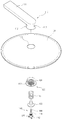
1 is an exploded perspective view showing a lid of a cooking vessel provided with a thermostat according to the present invention.
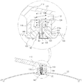
2 is a cross-sectional view illustrating a lid of a cooking vessel provided with a thermostat according to the present invention.
3 is an operational sectional view showing a lid of a cooking vessel provided with a thermostat according to the present invention.
The terms and words used in the present specification and claims should not be construed as limited to ordinary or dictionary meanings and the inventor may properly define the concept of the term to describe its invention in the best possible way And should be construed in accordance with the principles and meanings and concepts consistent with the technical idea of the present invention.
Hereinafter, preferred embodiments of the present invention will be described in detail with reference to the accompanying drawings.
FIG. 1 is an exploded perspective view showing a lid of a cooking vessel provided with a thermostat according to the present invention, and FIG. 2 is a sectional view showing a lid of a cooking vessel provided with a thermostat according to the present invention.
Referring to the drawings, the lid of the cooking utensil provided with the thermostat according to the present invention is installed on the upper part of the lid so that the lid can be held by the user, and an
The
The
The
Particularly, a
A
A
The
An
At this time, the
When the
Meanwhile, the
The
A
At this time, an o-ring (not shown) is interposed between the
The upper end of the
The operation of the cooker with the thermostat according to the present invention will now be described with reference to FIG.
3 is an operational sectional view showing a lid of a cooking vessel provided with a thermostat according to the present invention. Referring to the drawings, when a
Thus, the steam generated by the heating of the cooking vessel heats the
When the
On the other hand, when heating of the cooking vessel is stopped, the internal temperature of the cooking vessel is lowered, and the
At this time, the
According to the lid of the cooking vessel having the thermostat according to the present invention, the
While the present invention has been described with reference to exemplary embodiments, it is to be understood that the invention is not limited to the disclosed exemplary embodiments, but, on the contrary, is intended to cover various modifications and equivalent arrangements included within the spirit and scope of the appended claims. .
100: lid 101: through hole
110: Handle 111:
112: holder 113: exhaust hole
114: valve seat 115: coil spring
116: fastening hole 120: connector
121: Inlet hole 122: Inclined surface
123: shoulder portion 124: fastening portion
125: Supporter 130: Valve
140: thermostat 141: wax
142: wax chamber 144: piston
146: guider 146a: guide hole
Claims (4)
A connector inserted into the through hole formed in the lid and engaged with the handle;
A valve provided in an exhaust hole formed in the handle to control opening and closing of the exhaust hole; And
And a thermostat installed in the connector and generating a displacement of the valve according to a temperature change to open and close the exhaust hole.
Wherein the valve is made of a material exhibiting an elastic restoring force.
Wherein the connector is provided with a valve seat on which the valve is placed, and the valve is provided with an elastic member for exerting an elastic force to closely contact the valve with the valve seat.
The thermostat
A wax chamber supported by the connector and filled with wax;
A piston that adjusts the displacement of the valve as the wax expands; And
And a guider unitarily coupled to the wax chamber and guiding the movement of the piston in accordance with the expansion of the wax.
Priority Applications (1)
| Application Number | Priority Date | Filing Date | Title |
|---|---|---|---|
| KR1020150119008A KR101738479B1 (en) | 2015-08-24 | 2015-08-24 | Cooking vessel having a thermostat |
Applications Claiming Priority (1)
| Application Number | Priority Date | Filing Date | Title |
|---|---|---|---|
| KR1020150119008A KR101738479B1 (en) | 2015-08-24 | 2015-08-24 | Cooking vessel having a thermostat |
Publications (2)
| Publication Number | Publication Date |
|---|---|
| KR20170024227A true KR20170024227A (en) | 2017-03-07 |
| KR101738479B1 KR101738479B1 (en) | 2017-05-23 |
Family
ID=58411594
Family Applications (1)
| Application Number | Title | Priority Date | Filing Date |
|---|---|---|---|
| KR1020150119008A KR101738479B1 (en) | 2015-08-24 | 2015-08-24 | Cooking vessel having a thermostat |
Country Status (1)
| Country | Link |
|---|---|
| KR (1) | KR101738479B1 (en) |
Cited By (1)
| Publication number | Priority date | Publication date | Assignee | Title |
|---|---|---|---|---|
| CN112369915A (en) * | 2020-11-03 | 2021-02-19 | 珠海格力电器股份有限公司 | Cooking equipment control method and device, cooking equipment and storage medium |
Citations (2)
| Publication number | Priority date | Publication date | Assignee | Title |
|---|---|---|---|---|
| KR200359497Y1 (en) | 2004-06-01 | 2004-08-18 | 김성곤 | A containerlid for preventing overflow |
| KR200368219Y1 (en) | 2004-08-23 | 2004-11-17 | 주식회사 해피콜 | lip for cooking receptacle |
Family Cites Families (2)
| Publication number | Priority date | Publication date | Assignee | Title |
|---|---|---|---|---|
| KR200280600Y1 (en) | 2002-04-01 | 2002-07-04 | 박희돈 | Stream discharge apparatus of kitchen utensil lid |
| KR100646036B1 (en) | 2005-04-29 | 2006-11-14 | 손태순 | A containerlid for preventing overflow |
-
2015
- 2015-08-24 KR KR1020150119008A patent/KR101738479B1/en active IP Right Grant
Patent Citations (2)
| Publication number | Priority date | Publication date | Assignee | Title |
|---|---|---|---|---|
| KR200359497Y1 (en) | 2004-06-01 | 2004-08-18 | 김성곤 | A containerlid for preventing overflow |
| KR200368219Y1 (en) | 2004-08-23 | 2004-11-17 | 주식회사 해피콜 | lip for cooking receptacle |
Cited By (2)
| Publication number | Priority date | Publication date | Assignee | Title |
|---|---|---|---|---|
| CN112369915A (en) * | 2020-11-03 | 2021-02-19 | 珠海格力电器股份有限公司 | Cooking equipment control method and device, cooking equipment and storage medium |
| CN112369915B (en) * | 2020-11-03 | 2022-03-01 | 珠海格力电器股份有限公司 | Cooking equipment control method and device, cooking equipment and storage medium |
Also Published As
| Publication number | Publication date |
|---|---|
| KR101738479B1 (en) | 2017-05-23 |
Similar Documents
| Publication | Publication Date | Title |
|---|---|---|
| US4490597A (en) | Microwave permeable pressure compensating container | |
| US8393262B1 (en) | Pressure cooker with pressure relief handle | |
| AU2014319872B2 (en) | Pressure cooker | |
| JP5200000B2 (en) | Pressure cooker with pressure reduction control mechanism | |
| JP6294000B2 (en) | Extraction valve for pressure cooker | |
| KR20030044585A (en) | Steam exhaust device of air pocket in air-core pan | |
| JP2006075606A (en) | Decompression cooker and cooking method of food using it | |
| KR20180021845A (en) | Heating cooker and cover | |
| KR101904403B1 (en) | electric cooker | |
| KR101340898B1 (en) | multiple use boil cooker | |
| JP2007503236A (en) | Equipment for cooking food under pressure | |
| KR20110137500A (en) | Double pressure vessel using a chemical heating element | |
| KR101738479B1 (en) | Cooking vessel having a thermostat | |
| KR101409033B1 (en) | A lid for cool pot having overflow preventing function | |
| KR200391165Y1 (en) | Structure of controling a pressure in a cooking pot for preventing overflowing-food | |
| US20060289538A1 (en) | Sleeve-suspended and color-coded safety valve for a pressure cooker and a pressure cooker using the same | |
| KR101343151B1 (en) | A lid for cool pot having overflow preventing function | |
| KR102130609B1 (en) | Energy economizing type food steamer | |
| JP3828456B2 (en) | Steam escape structure in rice cooker | |
| KR101842892B1 (en) | Device for discharging steam out of pressure cooker | |
| KR200312275Y1 (en) | Cooker having packing | |
| KR20180026167A (en) | Thermal cover assembly for electric pressure rice cooker | |
| KR102357794B1 (en) | Control method of electric pressure cooker | |
| KR100230464B1 (en) | Solenoid for a combined cooker and electric pressure kettle | |
| KR101912357B1 (en) | Thermal cover assembly for electric pressure rice cooker |
Legal Events
| Date | Code | Title | Description |
|---|---|---|---|
| A201 | Request for examination | ||
| E902 | Notification of reason for refusal | ||
| E701 | Decision to grant or registration of patent right | ||
| GRNT | Written decision to grant |