KR20170016007A - Lithographic apparatus, method of transferring a substrate and device manufacturing method - Google Patents
Lithographic apparatus, method of transferring a substrate and device manufacturing method Download PDFInfo
- Publication number
- KR20170016007A KR20170016007A KR1020177001213A KR20177001213A KR20170016007A KR 20170016007 A KR20170016007 A KR 20170016007A KR 1020177001213 A KR1020177001213 A KR 1020177001213A KR 20177001213 A KR20177001213 A KR 20177001213A KR 20170016007 A KR20170016007 A KR 20170016007A
- Authority
- KR
- South Korea
- Prior art keywords
- substrate
- drying station
- liquid
- exposure
- post
- Prior art date
Links
- 239000000758 substrate Substances 0.000 title claims abstract description 541
- 238000000034 method Methods 0.000 title claims abstract description 50
- 238000004519 manufacturing process Methods 0.000 title description 8
- 238000001035 drying Methods 0.000 claims abstract description 285
- 239000007788 liquid Substances 0.000 claims abstract description 163
- 238000012546 transfer Methods 0.000 claims abstract description 6
- 230000005855 radiation Effects 0.000 claims description 32
- XLYOFNOQVPJJNP-UHFFFAOYSA-N water Substances O XLYOFNOQVPJJNP-UHFFFAOYSA-N 0.000 claims description 24
- 238000003860 storage Methods 0.000 claims description 23
- 230000004308 accommodation Effects 0.000 claims description 2
- 238000000605 extraction Methods 0.000 description 28
- 238000000059 patterning Methods 0.000 description 23
- 238000007654 immersion Methods 0.000 description 16
- 238000011084 recovery Methods 0.000 description 13
- 238000005286 illumination Methods 0.000 description 12
- 230000003287 optical effect Effects 0.000 description 8
- 230000007547 defect Effects 0.000 description 6
- 239000010410 layer Substances 0.000 description 6
- -1 e.g. Substances 0.000 description 5
- 239000012530 fluid Substances 0.000 description 4
- 238000005259 measurement Methods 0.000 description 4
- 238000009826 distribution Methods 0.000 description 3
- 230000000694 effects Effects 0.000 description 3
- 239000000284 extract Substances 0.000 description 3
- 238000011144 upstream manufacturing Methods 0.000 description 3
- 230000015556 catabolic process Effects 0.000 description 2
- 238000006731 degradation reaction Methods 0.000 description 2
- 238000013461 design Methods 0.000 description 2
- 230000002706 hydrostatic effect Effects 0.000 description 2
- 238000001459 lithography Methods 0.000 description 2
- 239000011159 matrix material Substances 0.000 description 2
- 239000002245 particle Substances 0.000 description 2
- 230000010363 phase shift Effects 0.000 description 2
- 229920002120 photoresistant polymer Polymers 0.000 description 2
- 239000011148 porous material Substances 0.000 description 2
- 238000012545 processing Methods 0.000 description 2
- 230000001154 acute effect Effects 0.000 description 1
- 230000002411 adverse Effects 0.000 description 1
- 230000003466 anti-cipated effect Effects 0.000 description 1
- 238000000149 argon plasma sintering Methods 0.000 description 1
- 238000003491 array Methods 0.000 description 1
- 230000002238 attenuated effect Effects 0.000 description 1
- 230000003247 decreasing effect Effects 0.000 description 1
- 238000001514 detection method Methods 0.000 description 1
- 238000011161 development Methods 0.000 description 1
- 230000009977 dual effect Effects 0.000 description 1
- 238000010894 electron beam technology Methods 0.000 description 1
- 238000005530 etching Methods 0.000 description 1
- 239000010408 film Substances 0.000 description 1
- 238000000671 immersion lithography Methods 0.000 description 1
- 238000007689 inspection Methods 0.000 description 1
- 238000010884 ion-beam technique Methods 0.000 description 1
- 239000002346 layers by function Substances 0.000 description 1
- 230000000670 limiting effect Effects 0.000 description 1
- 239000004973 liquid crystal related substance Substances 0.000 description 1
- 230000005381 magnetic domain Effects 0.000 description 1
- 230000015654 memory Effects 0.000 description 1
- QSHDDOUJBYECFT-UHFFFAOYSA-N mercury Chemical compound [Hg] QSHDDOUJBYECFT-UHFFFAOYSA-N 0.000 description 1
- 229910052753 mercury Inorganic materials 0.000 description 1
- 238000012986 modification Methods 0.000 description 1
- 230000004048 modification Effects 0.000 description 1
- 210000001747 pupil Anatomy 0.000 description 1
- 230000002829 reductive effect Effects 0.000 description 1
- 230000000717 retained effect Effects 0.000 description 1
- 238000007493 shaping process Methods 0.000 description 1
- 239000002356 single layer Substances 0.000 description 1
- 239000002904 solvent Substances 0.000 description 1
- 230000006641 stabilisation Effects 0.000 description 1
- 238000011105 stabilization Methods 0.000 description 1
- 239000000126 substance Substances 0.000 description 1
- 239000010409 thin film Substances 0.000 description 1
- 210000000707 wrist Anatomy 0.000 description 1
Images


Classifications
-
- H—ELECTRICITY
- H01—ELECTRIC ELEMENTS
- H01L—SEMICONDUCTOR DEVICES NOT COVERED BY CLASS H10
- H01L21/00—Processes or apparatus adapted for the manufacture or treatment of semiconductor or solid state devices or of parts thereof
- H01L21/67—Apparatus specially adapted for handling semiconductor or electric solid state devices during manufacture or treatment thereof; Apparatus specially adapted for handling wafers during manufacture or treatment of semiconductor or electric solid state devices or components ; Apparatus not specifically provided for elsewhere
- H01L21/67005—Apparatus not specifically provided for elsewhere
- H01L21/67011—Apparatus for manufacture or treatment
- H01L21/67017—Apparatus for fluid treatment
- H01L21/67028—Apparatus for fluid treatment for cleaning followed by drying, rinsing, stripping, blasting or the like
- H01L21/67034—Apparatus for fluid treatment for cleaning followed by drying, rinsing, stripping, blasting or the like for drying
-
- G—PHYSICS
- G03—PHOTOGRAPHY; CINEMATOGRAPHY; ANALOGOUS TECHNIQUES USING WAVES OTHER THAN OPTICAL WAVES; ELECTROGRAPHY; HOLOGRAPHY
- G03F—PHOTOMECHANICAL PRODUCTION OF TEXTURED OR PATTERNED SURFACES, e.g. FOR PRINTING, FOR PROCESSING OF SEMICONDUCTOR DEVICES; MATERIALS THEREFOR; ORIGINALS THEREFOR; APPARATUS SPECIALLY ADAPTED THEREFOR
- G03F7/00—Photomechanical, e.g. photolithographic, production of textured or patterned surfaces, e.g. printing surfaces; Materials therefor, e.g. comprising photoresists; Apparatus specially adapted therefor
- G03F7/70—Microphotolithographic exposure; Apparatus therefor
- G03F7/70216—Mask projection systems
- G03F7/70341—Details of immersion lithography aspects, e.g. exposure media or control of immersion liquid supply
-
- G—PHYSICS
- G03—PHOTOGRAPHY; CINEMATOGRAPHY; ANALOGOUS TECHNIQUES USING WAVES OTHER THAN OPTICAL WAVES; ELECTROGRAPHY; HOLOGRAPHY
- G03F—PHOTOMECHANICAL PRODUCTION OF TEXTURED OR PATTERNED SURFACES, e.g. FOR PRINTING, FOR PROCESSING OF SEMICONDUCTOR DEVICES; MATERIALS THEREFOR; ORIGINALS THEREFOR; APPARATUS SPECIALLY ADAPTED THEREFOR
- G03F7/00—Photomechanical, e.g. photolithographic, production of textured or patterned surfaces, e.g. printing surfaces; Materials therefor, e.g. comprising photoresists; Apparatus specially adapted therefor
- G03F7/16—Coating processes; Apparatus therefor
- G03F7/168—Finishing the coated layer, e.g. drying, baking, soaking
-
- G—PHYSICS
- G03—PHOTOGRAPHY; CINEMATOGRAPHY; ANALOGOUS TECHNIQUES USING WAVES OTHER THAN OPTICAL WAVES; ELECTROGRAPHY; HOLOGRAPHY
- G03F—PHOTOMECHANICAL PRODUCTION OF TEXTURED OR PATTERNED SURFACES, e.g. FOR PRINTING, FOR PROCESSING OF SEMICONDUCTOR DEVICES; MATERIALS THEREFOR; ORIGINALS THEREFOR; APPARATUS SPECIALLY ADAPTED THEREFOR
- G03F7/00—Photomechanical, e.g. photolithographic, production of textured or patterned surfaces, e.g. printing surfaces; Materials therefor, e.g. comprising photoresists; Apparatus specially adapted therefor
- G03F7/70—Microphotolithographic exposure; Apparatus therefor
- G03F7/70691—Handling of masks or workpieces
- G03F7/70733—Handling masks and workpieces, e.g. exchange of workpiece or mask, transport of workpiece or mask
- G03F7/7075—Handling workpieces outside exposure position, e.g. SMIF box
-
- G—PHYSICS
- G03—PHOTOGRAPHY; CINEMATOGRAPHY; ANALOGOUS TECHNIQUES USING WAVES OTHER THAN OPTICAL WAVES; ELECTROGRAPHY; HOLOGRAPHY
- G03F—PHOTOMECHANICAL PRODUCTION OF TEXTURED OR PATTERNED SURFACES, e.g. FOR PRINTING, FOR PROCESSING OF SEMICONDUCTOR DEVICES; MATERIALS THEREFOR; ORIGINALS THEREFOR; APPARATUS SPECIALLY ADAPTED THEREFOR
- G03F7/00—Photomechanical, e.g. photolithographic, production of textured or patterned surfaces, e.g. printing surfaces; Materials therefor, e.g. comprising photoresists; Apparatus specially adapted therefor
- G03F7/70—Microphotolithographic exposure; Apparatus therefor
- G03F7/708—Construction of apparatus, e.g. environment aspects, hygiene aspects or materials
- G03F7/70808—Construction details, e.g. housing, load-lock, seals or windows for passing light in or out of apparatus
- G03F7/70825—Mounting of individual elements, e.g. mounts, holders or supports
-
- G—PHYSICS
- G03—PHOTOGRAPHY; CINEMATOGRAPHY; ANALOGOUS TECHNIQUES USING WAVES OTHER THAN OPTICAL WAVES; ELECTROGRAPHY; HOLOGRAPHY
- G03F—PHOTOMECHANICAL PRODUCTION OF TEXTURED OR PATTERNED SURFACES, e.g. FOR PRINTING, FOR PROCESSING OF SEMICONDUCTOR DEVICES; MATERIALS THEREFOR; ORIGINALS THEREFOR; APPARATUS SPECIALLY ADAPTED THEREFOR
- G03F7/00—Photomechanical, e.g. photolithographic, production of textured or patterned surfaces, e.g. printing surfaces; Materials therefor, e.g. comprising photoresists; Apparatus specially adapted therefor
- G03F7/70—Microphotolithographic exposure; Apparatus therefor
- G03F7/708—Construction of apparatus, e.g. environment aspects, hygiene aspects or materials
- G03F7/70991—Connection with other apparatus, e.g. multiple exposure stations, particular arrangement of exposure apparatus and pre-exposure and/or post-exposure apparatus; Shared apparatus, e.g. having shared radiation source, shared mask or workpiece stage, shared base-plate; Utilities, e.g. cable, pipe or wireless arrangements for data, power, fluids or vacuum
-
- H—ELECTRICITY
- H01—ELECTRIC ELEMENTS
- H01L—SEMICONDUCTOR DEVICES NOT COVERED BY CLASS H10
- H01L21/00—Processes or apparatus adapted for the manufacture or treatment of semiconductor or solid state devices or of parts thereof
- H01L21/02—Manufacture or treatment of semiconductor devices or of parts thereof
- H01L21/04—Manufacture or treatment of semiconductor devices or of parts thereof the devices having potential barriers, e.g. a PN junction, depletion layer or carrier concentration layer
- H01L21/50—Assembly of semiconductor devices using processes or apparatus not provided for in a single one of the subgroups H01L21/06 - H01L21/326, e.g. sealing of a cap to a base of a container
- H01L21/52—Mounting semiconductor bodies in containers
-
- H—ELECTRICITY
- H01—ELECTRIC ELEMENTS
- H01L—SEMICONDUCTOR DEVICES NOT COVERED BY CLASS H10
- H01L21/00—Processes or apparatus adapted for the manufacture or treatment of semiconductor or solid state devices or of parts thereof
- H01L21/67—Apparatus specially adapted for handling semiconductor or electric solid state devices during manufacture or treatment thereof; Apparatus specially adapted for handling wafers during manufacture or treatment of semiconductor or electric solid state devices or components ; Apparatus not specifically provided for elsewhere
- H01L21/67005—Apparatus not specifically provided for elsewhere
- H01L21/67011—Apparatus for manufacture or treatment
- H01L21/67017—Apparatus for fluid treatment
- H01L21/67028—Apparatus for fluid treatment for cleaning followed by drying, rinsing, stripping, blasting or the like
- H01L21/6704—Apparatus for fluid treatment for cleaning followed by drying, rinsing, stripping, blasting or the like for wet cleaning or washing
-
- H—ELECTRICITY
- H01—ELECTRIC ELEMENTS
- H01L—SEMICONDUCTOR DEVICES NOT COVERED BY CLASS H10
- H01L21/00—Processes or apparatus adapted for the manufacture or treatment of semiconductor or solid state devices or of parts thereof
- H01L21/67—Apparatus specially adapted for handling semiconductor or electric solid state devices during manufacture or treatment thereof; Apparatus specially adapted for handling wafers during manufacture or treatment of semiconductor or electric solid state devices or components ; Apparatus not specifically provided for elsewhere
- H01L21/67005—Apparatus not specifically provided for elsewhere
- H01L21/67011—Apparatus for manufacture or treatment
- H01L21/67155—Apparatus for manufacturing or treating in a plurality of work-stations
- H01L21/67161—Apparatus for manufacturing or treating in a plurality of work-stations characterized by the layout of the process chambers
- H01L21/67178—Apparatus for manufacturing or treating in a plurality of work-stations characterized by the layout of the process chambers vertical arrangement
-
- H—ELECTRICITY
- H01—ELECTRIC ELEMENTS
- H01L—SEMICONDUCTOR DEVICES NOT COVERED BY CLASS H10
- H01L21/00—Processes or apparatus adapted for the manufacture or treatment of semiconductor or solid state devices or of parts thereof
- H01L21/67—Apparatus specially adapted for handling semiconductor or electric solid state devices during manufacture or treatment thereof; Apparatus specially adapted for handling wafers during manufacture or treatment of semiconductor or electric solid state devices or components ; Apparatus not specifically provided for elsewhere
- H01L21/67005—Apparatus not specifically provided for elsewhere
- H01L21/67011—Apparatus for manufacture or treatment
- H01L21/67155—Apparatus for manufacturing or treating in a plurality of work-stations
- H01L21/67207—Apparatus for manufacturing or treating in a plurality of work-stations comprising a chamber adapted to a particular process
- H01L21/67225—Apparatus for manufacturing or treating in a plurality of work-stations comprising a chamber adapted to a particular process comprising at least one lithography chamber
-
- H—ELECTRICITY
- H01—ELECTRIC ELEMENTS
- H01L—SEMICONDUCTOR DEVICES NOT COVERED BY CLASS H10
- H01L21/00—Processes or apparatus adapted for the manufacture or treatment of semiconductor or solid state devices or of parts thereof
- H01L21/67—Apparatus specially adapted for handling semiconductor or electric solid state devices during manufacture or treatment thereof; Apparatus specially adapted for handling wafers during manufacture or treatment of semiconductor or electric solid state devices or components ; Apparatus not specifically provided for elsewhere
- H01L21/677—Apparatus specially adapted for handling semiconductor or electric solid state devices during manufacture or treatment thereof; Apparatus specially adapted for handling wafers during manufacture or treatment of semiconductor or electric solid state devices or components ; Apparatus not specifically provided for elsewhere for conveying, e.g. between different workstations
- H01L21/67739—Apparatus specially adapted for handling semiconductor or electric solid state devices during manufacture or treatment thereof; Apparatus specially adapted for handling wafers during manufacture or treatment of semiconductor or electric solid state devices or components ; Apparatus not specifically provided for elsewhere for conveying, e.g. between different workstations into and out of processing chamber
- H01L21/67742—Mechanical parts of transfer devices
-
- H—ELECTRICITY
- H01—ELECTRIC ELEMENTS
- H01L—SEMICONDUCTOR DEVICES NOT COVERED BY CLASS H10
- H01L21/00—Processes or apparatus adapted for the manufacture or treatment of semiconductor or solid state devices or of parts thereof
- H01L21/67—Apparatus specially adapted for handling semiconductor or electric solid state devices during manufacture or treatment thereof; Apparatus specially adapted for handling wafers during manufacture or treatment of semiconductor or electric solid state devices or components ; Apparatus not specifically provided for elsewhere
- H01L21/677—Apparatus specially adapted for handling semiconductor or electric solid state devices during manufacture or treatment thereof; Apparatus specially adapted for handling wafers during manufacture or treatment of semiconductor or electric solid state devices or components ; Apparatus not specifically provided for elsewhere for conveying, e.g. between different workstations
- H01L21/67763—Apparatus specially adapted for handling semiconductor or electric solid state devices during manufacture or treatment thereof; Apparatus specially adapted for handling wafers during manufacture or treatment of semiconductor or electric solid state devices or components ; Apparatus not specifically provided for elsewhere for conveying, e.g. between different workstations the wafers being stored in a carrier, involving loading and unloading
- H01L21/67766—Mechanical parts of transfer devices
-
- H—ELECTRICITY
- H01—ELECTRIC ELEMENTS
- H01L—SEMICONDUCTOR DEVICES NOT COVERED BY CLASS H10
- H01L21/00—Processes or apparatus adapted for the manufacture or treatment of semiconductor or solid state devices or of parts thereof
- H01L21/67—Apparatus specially adapted for handling semiconductor or electric solid state devices during manufacture or treatment thereof; Apparatus specially adapted for handling wafers during manufacture or treatment of semiconductor or electric solid state devices or components ; Apparatus not specifically provided for elsewhere
- H01L21/677—Apparatus specially adapted for handling semiconductor or electric solid state devices during manufacture or treatment thereof; Apparatus specially adapted for handling wafers during manufacture or treatment of semiconductor or electric solid state devices or components ; Apparatus not specifically provided for elsewhere for conveying, e.g. between different workstations
- H01L21/67763—Apparatus specially adapted for handling semiconductor or electric solid state devices during manufacture or treatment thereof; Apparatus specially adapted for handling wafers during manufacture or treatment of semiconductor or electric solid state devices or components ; Apparatus not specifically provided for elsewhere for conveying, e.g. between different workstations the wafers being stored in a carrier, involving loading and unloading
- H01L21/67778—Apparatus specially adapted for handling semiconductor or electric solid state devices during manufacture or treatment thereof; Apparatus specially adapted for handling wafers during manufacture or treatment of semiconductor or electric solid state devices or components ; Apparatus not specifically provided for elsewhere for conveying, e.g. between different workstations the wafers being stored in a carrier, involving loading and unloading involving loading and unloading of wafers
Landscapes
- Engineering & Computer Science (AREA)
- Physics & Mathematics (AREA)
- General Physics & Mathematics (AREA)
- Condensed Matter Physics & Semiconductors (AREA)
- Manufacturing & Machinery (AREA)
- Computer Hardware Design (AREA)
- Microelectronics & Electronic Packaging (AREA)
- Power Engineering (AREA)
- Health & Medical Sciences (AREA)
- Environmental & Geological Engineering (AREA)
- Epidemiology (AREA)
- Public Health (AREA)
- Robotics (AREA)
- Computer Networks & Wireless Communication (AREA)
- Exposure And Positioning Against Photoresist Photosensitive Materials (AREA)
- Container, Conveyance, Adherence, Positioning, Of Wafer (AREA)
Abstract
리소그래피 장치는 기판 테이블, 후-노광 핸들링 모듈, 기판 핸들링 로봇 및 건조 스테이션을 포함한다. 기판 테이블은 노광 공정을 위해 기판을 지지하도록 구성된다. 후-노광 핸들링 모듈은 기판 후-노광을 핸들링하기 위한 모듈이다. 기판 핸들링 로봇은 기판 테이블로부터 기판 언로딩 경로를 따라 후-노광 핸들링 모듈 내로 기판을 이송하도록 구성된다. 건조 스테이션은 기판의 표면으로부터 액체를 능동적으로 제거하도록 구성된다. 건조 스테이션은 기판 언로딩 경로에 위치된다. 건조 스테이션은 후-노광 핸들링 모듈에 위치된다. 후-노광 핸들링 모듈은 웨이퍼 핸들러일 수 있다.The lithographic apparatus includes a substrate table, a post-exposure handling module, a substrate handling robot, and a drying station. The substrate table is configured to support the substrate for an exposure process. The post-exposure handling module is a module for handling post-substrate exposure. The substrate handling robot is configured to transfer the substrate from the substrate table along the substrate unloading path into the post-exposure handling module. The drying station is configured to actively remove liquid from the surface of the substrate. The drying station is located in the substrate unloading path. The drying station is located in a post-exposure handling module. The post-exposure handling module may be a wafer handler.
Description
본 출원은 2014년 6월 16일에 출원된 EP 출원 14172626.5, 2014년 7월 25일에 출원된 EP 출원 14178554.3, 및 2014년 12월 18일에 출원된 EP 출원 14198779.2의 이익을 주장하며, 이는 본 명세서에서 전문이 인용 참조된다.The present application claims the benefit of EP Application 14172626.5, filed June 16, 2014, EP Application 14178554.3, filed July 25, 2014, and EP Application 14198779.2, filed December 18, 2014, Reference is made to the text in the specification.
본 발명은 리소그래피 장치, 기판을 이송하는 방법 및 디바이스 제조 방법에 관한 것이다.The present invention relates to a lithographic apparatus, a method of transferring a substrate, and a device manufacturing method.
리소그래피 장치는 기판 상으로, 통상적으로는 기판의 타겟부 상으로 원하는 패턴을 적용시키는 기계이다. 리소그래피 장치는, 예를 들어 집적 회로(IC)의 제조에 사용될 수 있다.A lithographic apparatus is a machine that applies a desired pattern onto a substrate, typically onto a target portion of the substrate. The lithographic apparatus may be used, for example, in the manufacture of integrated circuits (ICs).
침지 리소그래피(immersion lithography)에서는, 노광 공정 후 기판 상의 레지스트에 액체, 예를 들어 물이 남게 될 수 있다. 액체는 레지스트를 저하시킬 수 있다. 액체가 남아있다면, 레지스트의 저하는 결함을 유도할 수 있다.In immersion lithography, liquids, e.g., water, can remain in the resist on the substrate after the exposure process. The liquid may degrade the resist. If a liquid remains, the degradation of the resist can lead to defects.
리소그래피 장치의 스루풋(throughput)에 부정적인 영향을 주지 않고, 잔류 액체에 의해 야기되는 결함을 감소시키는 것이 바람직하다.It is desirable to reduce the defects caused by the residual liquid without adversely affecting the throughput of the lithographic apparatus.
본 발명의 일 실시형태에 따르면, 노광 공정을 위해 기판을 지지하도록 구성되는 기판 테이블 - 노광 공정에서 기판은 액체를 통해 패턴을 형성하도록 방사선 빔에 노광됨 -; 기판 후-노광(substrate post-exposure)을 핸들링(handle)하는 후-노광 핸들링 모듈; 기판 테이블로부터 기판 언로딩 경로(substrate unloading path)를 따라 후-노광 핸들링 모듈 내로 기판을 이송하도록 구성되는 기판 핸들링 로봇; 및 기판의 표면으로부터 액체를 능동적으로(actively) 제거하도록 구성되는 건조 스테이션을 포함하는 리소그래피 장치가 제공되고, 건조 스테이션은 기판 언로딩 경로 및 후-노광 핸들링 모듈에 위치되어, 기판이 기판 언로딩 경로를 따라 이송 시 건조 스테이션을 완전히 통과할 수 있다.According to one embodiment of the present invention, a substrate table configured to support a substrate for an exposure process, the substrate in the exposure process being exposed to a radiation beam to form a pattern through the liquid; A post-exposure handling module that handles substrate post-exposure; A substrate handling robot configured to transfer a substrate into a post-exposure handling module along a substrate unloading path from a substrate table; And a drying station configured to actively remove liquid from the surface of the substrate, wherein the drying station is located in a substrate unloading path and a post-exposure handling module, To pass completely through the drying station.
본 발명의 일 실시형태에 따르면, 리소그래피 장치에서 기판을 이송하는 방법이 제공되고, 본 방법은: 노광 공정을 위해 기판 테이블에 기판을 지지하는 단계 - 노광 공정에서 기판은 액체를 통해 패턴을 형성하도록 방사선 빔에 노광됨 -; 기판 테이블로부터 기판 언로딩 경로를 따라 기판 후-노광을 핸들링하는 후-노광 핸들링 모듈 내로 기판을 이송하는 단계; 및 건조 스테이션에 의해 기판의 표면으로부터 액체를 능동적으로 제거하는 단계를 포함하고, 액체의 능동 제거는 기판 언로딩 경로 및 후-노광 핸들링 모듈에서 수행되어, 기판이 기판 언로딩 경로를 따라 이송 시 건조 스테이션을 완전히 통과한다.According to an aspect of the invention, there is provided a method of transferring a substrate in a lithographic apparatus, the method comprising: supporting the substrate on a substrate table for an exposure process, the substrate in the exposure process forming a pattern through the liquid Exposed to a radiation beam; Transferring the substrate from the substrate table into a post-exposure handling module that handles substrate post-exposure along a substrate unloading path; And actively removing liquid from the surface of the substrate by a drying station, wherein active removal of the liquid is performed in a substrate unloading path and in a post-exposure handling module such that the substrate is dried during transport along a substrate unloading path It completely passes through the station.
이제, 대응하는 참조 부호들이 대응하는 부분들을 나타내는 첨부된 개략적인 도면들을 참조하여, 단지 예시의 방식으로만 본 발명의 실시예들을 설명할 것이다:
도 1은 본 발명의 일 실시예에 따른 리소그래피 장치를 도시하는 도면;
도 2는 본 발명의 일 실시예에 따른 리소그래피 장치의 일부분을 도시하는 도면;
도 3은 본 발명의 일 실시예에 따른 리소그래피 장치의 일부분을 도시하는 도면;
도 4 및 도 5는 본 발명의 일 실시예에 따른 리소그래피 장치의 일부분을 도시하는 도면;
도 6 내지 도 8은 본 발명의 일 실시예에 따른 리소그래피 장치를 개략적으로 도시하는 도면;
도 9 내지 도 14는 본 발명의 일 실시예에 따른 리소그래피 장치의 일부분을 도시하는 도면; 및
도 15 및 도 16은 각각 본 발명의 일 실시예에 따른 건조 스테이션을 도시하는 도면이다.Reference will now be made to the embodiments of the present invention, by way of example only, with reference to the appended schematic drawings in which corresponding reference symbols indicate corresponding parts, and in which:
1 illustrates a lithographic apparatus according to one embodiment of the present invention;
Figure 2 illustrates a portion of a lithographic apparatus according to one embodiment of the present invention;
Figure 3 illustrates a portion of a lithographic apparatus according to one embodiment of the present invention;
Figures 4 and 5 depict a portion of a lithographic apparatus according to one embodiment of the present invention;
Figures 6 to 8 schematically illustrate a lithographic apparatus according to one embodiment of the present invention;
Figures 9-14 illustrate a portion of a lithographic apparatus according to one embodiment of the present invention; And
15 and 16 are views showing a drying station according to an embodiment of the present invention, respectively.
도 1은 본 발명의 일 실시예에 따른 리소그래피 장치(100)를 개략적으로 도시한다. 리소그래피 장치(100)는 방사선 빔(B)(예를 들어, UV 방사선 또는 여하한의 다른 적합한 방사선)을 컨디셔닝하도록 구성된 조명 시스템(일루미네이터)(IL), 및 패터닝 디바이스(예를 들어, 마스크)(MA)를 지지하도록 구성되고, 소정 파라미터들에 따라 패터닝 디바이스(MA)를 정확히 위치시키도록 구성된 제 1 위치설정 디바이스(PM)에 연결된 마스크 지지 구조체(예를 들어, 마스크 테이블)(MT)를 포함한다. 또한, 리소그래피 장치(100)는 기판(예를 들어, 레지스트-코팅된 웨이퍼)(W)을 유지하도록 구성되고, 소정 파라미터들에 따라 기판(W)을 정확히 위치시키도록 구성된 제 2 위치설정 디바이스(PW)에 연결된 기판 테이블(예를 들어, 웨이퍼 테이블)(WT)을 포함한다. 또한, 리소그래피 장치(100)는 기판(W)의 (예를 들어, 하나 이상의 다이를 포함하는) 타겟부(C) 상으로 패터닝 디바이스(MA)에 의해 방사선 빔(B)에 부여된 패턴을 투영하도록 구성된 투영 시스템(예를 들어, 굴절 투영 렌즈 시스템)(PS)을 포함한다.Figure 1 schematically depicts a
조명 시스템(IL)은 방사선을 지향, 성형 또는 제어하기 위하여, 굴절, 반사, 자기, 전자기, 정전기 또는 다른 형태의 광학 구성요소들, 또는 이의 여하한의 조합과 같은 다양한 형태의 광학 구성요소들을 포함할 수 있다.The illumination system IL includes various types of optical components, such as refractive, reflective, magnetic, electromagnetic, electrostatic or other types of optical components, or any combination thereof, for directing, shaping, or controlling radiation can do.
마스크 지지 구조체(MT)는 패터닝 디바이스(MA)를 지지, 즉 그 무게를 견딘다. 마스크 지지 구조체(MT)는 패터닝 디바이스(MA)의 방위, 리소그래피 장치(100)의 디자인, 및 예를 들어 패터닝 디바이스(MA)가 진공 환경에서 유지되는지의 여부와 같은 다른 조건들에 의존하는 방식으로 패터닝 디바이스(MA)를 유지한다. 마스크 지지 구조체(MT)는 패터닝 디바이스를 유지하기 위해 기계적, 진공, 정전기, 또는 다른 클램핑 기술들을 이용할 수 있다. 마스크 지지 구조체(MT)는, 예를 들어 필요에 따라 고정되거나 이동가능할 수 있는 프레임 또는 테이블일 수 있다. 마스크 지지 구조체(MT)는, 패터닝 디바이스(MA)가 예를 들어 투영 시스템(PS)에 대해 원하는 위치에 있을 것을 보장할 수 있다. 본 명세서의 "레티클" 또는 "마스크"라는 용어의 어떠한 사용도 "패터닝 디바이스"라는 좀 더 일반적인 용어와 동의어로 간주될 수 있다.The mask support structure MT supports, i.e. bears the weight of, the patterning device MA. The mask support structure MT is movable in a manner that depends on the orientation of the patterning device MA, the design of the
본 명세서에서 사용되는 "패터닝 디바이스"라는 용어는, 기판(W)의 타겟부(C)에 패턴을 생성하기 위해서, 방사선 빔(B)의 단면에 패턴을 부여하는 데 사용될 수 있는 여하한의 디바이스를 언급하는 것으로 폭넓게 해석되어야 한다. 방사선 빔(B)에 부여된 패턴은, 예를 들어 패턴이 위상-시프팅 피처(phase-shifting feature) 또는 소위 어시스트 피처(assist feature)들을 포함하는 경우, 기판(W)의 타겟부(C) 내의 원하는 패턴과 정확히 일치하지 않을 수도 있다는 것을 유의하여야 한다. 어시스트 피처들은, 실제보다 더 밀집된 것처럼 격리된(isolated) 및/또는 반-격리된(semi-isolated) 디자인 피처들이 패터닝될 수 있도록 패터닝 디바이스(MA)에 배치될 수 있다. 일반적으로, 방사선 빔(B)에 부여된 패턴은 집적 회로와 같이 타겟부(C)에 생성될 디바이스의 특정 기능 층에 해당할 것이다.The term "patterning device " as used herein refers to any device that can be used to impart a pattern to a cross section of a radiation beam B, in order to create a pattern in a target portion C of the substrate W. [ Should be broadly interpreted as referring to < RTI ID = 0.0 > The pattern imparted to the radiation beam B may be applied to a target portion C of the substrate W if, for example, the pattern comprises a phase-shifting feature or so-called assist features. ≪ / RTI > may not exactly coincide with the desired pattern within the pattern. The assist features may be disposed in the patterning device MA such that isolated and / or semi-isolated design features may be patterned as if they were more dense than they actually are. In general, the pattern imparted to the radiation beam B will correspond to a particular functional layer of the device to be created in the target portion C, such as an integrated circuit.
패터닝 디바이스(MA)는 투과형 또는 반사형일 수 있다. 패터닝 디바이스의 예로는 마스크, 프로그램가능한 거울 어레이, 및 프로그램가능한 LCD 패널들을 포함한다. 마스크는 리소그래피 분야에서 잘 알려져 있으며, 다양한 하이브리드(hybrid) 마스크 타입들뿐만 아니라, 바이너리(binary)형, 교번 위상-시프트형 및 감쇠 위상-시프트형과 같은 마스크 타입들을 포함한다. 프로그램가능한 거울 어레이의 일 예시는 작은 거울들의 매트릭스 구성을 채택하며, 그 각각은 입사하는 방사선 빔을 상이한 방향으로 반사시키도록 개별적으로 기울어질 수 있다. 기울어진 거울들은 거울 매트릭스에 의해 반사되는 방사선 빔에 패턴을 부여한다.The patterning device MA may be transmissive or reflective. Examples of patterning devices include masks, programmable mirror arrays, and programmable LCD panels. Masks are well known in the lithography art and include mask types such as binary, alternating phase-shift, and attenuated phase-shift, as well as various hybrid mask types. One example of a programmable mirror array employs a matrix configuration of small mirrors, each of which can be individually tilted to reflect an incoming radiation beam in different directions. The tilted mirrors impart a pattern to the radiation beam reflected by the mirror matrix.
본 명세서에서 사용되는 "투영 시스템"이라는 용어는, 사용되는 노광 방사선에 대하여, 또는 침지 액체의 사용 또는 진공의 사용과 같은 다른 인자들에 대하여 적절하다면, 굴절, 반사, 카타디옵트릭(catadioptric), 자기, 전자기 및 정전기 광학 시스템, 또는 이의 여하한의 조합을 포함하는 여하한의 타입의 투영 시스템(PS)을 내포하는 것으로서 폭넓게 해석되어야 한다. 본 명세서의 "투영 렌즈"라는 용어의 어떠한 사용도 "투영 시스템"이라는 좀 더 일반적인 용어와 동의어로 간주될 수 있다.The term "projection system " used herein should be broadly interpreted as encompassing any type of projection system, including refractive, reflective, catadioptric, catadioptric, catadioptric, Should be broadly interpreted as encompassing any type of projection system (PS), including magnetic, electromagnetic and electrostatic optical systems, or any combination thereof. Any use of the term "projection lens" herein may be considered as synonymous with the more general term "projection system ".
조명 시스템(IL)은 방사선 빔(B)의 각도 세기 분포를 조정하도록 구성된 조정기(AD)를 포함할 수 있다. 일반적으로, 조명 시스템(IL)의 퓨필 평면의 세기 분포의 적어도 외반경 및/또는 내반경 크기(통상적으로, 각각 외측-σ 및 내측-σ라 함)가 조정될 수 있다. 또한, 조명 시스템(IL)은 인티그레이터(IN) 및 콘덴서(CN)와 같이, 다양한 다른 구성요소들을 포함할 수도 있다. 조명 시스템(IL)은 방사선 빔의 단면에 원하는 균일성 및 세기 분포를 갖기 위해, 방사선 빔(B)을 컨디셔닝하는 데 사용될 수 있다. 조명 시스템(IL)은 리소그래피 장치(100)의 일부분을 형성하는 것으로 간주될 수 있거나 간주되지 않을 수도 있다. 예를 들어, 조명 시스템(IL)은 리소그래피 장치(100)의 통합부일 수 있거나, 리소그래피 장치(100)로부터 별도의 개체일 수 있다. 후자의 경우, 리소그래피 장치(100)는 조명 시스템(IL)이 그 위에 장착되도록 구성될 수 있다. 선택적으로, 조명 시스템(IL)은 분리가능하며(detachable), (예를 들어, 리소그래피 장치 제조업자 또는 다른 공급자에 의해) 별도로 제공될 수도 있다.The illumination system IL may comprise an adjuster AD configured to adjust the angular intensity distribution of the radiation beam B. Generally, at least the outer and / or inner radial extent (commonly referred to as -outer and -inner, respectively) of the intensity distribution of the pupil plane of the illumination system IL can be adjusted. In addition, the illumination system IL may include various other components, such as an integrator IN and a condenser CN. The illumination system IL may be used to condition the radiation beam B to have a desired uniformity and intensity distribution in the cross section of the radiation beam. The illumination system IL may or may not be regarded as forming part of the
본 명세서에 도시된 바와 같이, 리소그래피 장치(100)는 (예를 들어, 투과 마스크를 채택하는) 투과형으로 구성된다. 대안적으로, 리소그래피 장치(100)는 (예를 들어, 앞서 언급된 바와 같은 타입의 프로그램가능한 거울 어레이를 채택하거나, 반사 마스크를 채택하는) 반사형으로 구성될 수 있다.As depicted herein, the
리소그래피 장치(100)는 2 개(듀얼 스테이지) 이상의 기판 테이블들(WT)[및/또는 2 이상의 마스크 지지 구조체들(MT), 예를 들어 마스크 테이블들]을 갖는 형태로 구성될 수 있다. 이러한 "다수 스테이지" 리소그래피 장치(100)에서는, 추가 기판 테이블들(WT) 및/또는 마스크 지지 구조체들(MT)이 병행하여 사용될 수 있거나, 하나 이상의 기판 테이블들(WT) 및/또는 마스크 지지 구조체들(MT)이 노광에 사용되고 있는 동안 하나 이상의 다른 기판 테이블들(WT) 및/또는 마스크 지지 구조체들(MT)에서는 준비작업 단계가 수행될 수 있다.The
패터닝 디바이스(MA)는 마스크 지지 구조체(MT)에 유지된다. 방사선 빔(B)은 패터닝 디바이스(MA)에 입사한다. 방사선 빔(B)은 패터닝 디바이스(MA)에 의해 패터닝된다. 패터닝 디바이스(MA)로부터 반사된 후, 방사선 빔(B)은 투영 시스템(PS)을 통과한다. 투영 시스템(PS)은 기판(W)의 타겟부(C) 상으로 방사선 빔(B)을 포커스한다. 제 1 위치설정기(PM) 및 제 1 위치 센서[예를 들어, 간섭계 디바이스(interferometric device), 리니어 인코더(linear encoder) 또는 용량성 센서(capacitive sensor)]는 방사선 빔(B)의 경로에 대해 패터닝 디바이스(MA)를 정확히 위치시키는 데 사용될 수 있다. 제 1 위치 센서는 도 1에 명확히 도시되어 있지 않다. 제 2 위치설정기(PW) 및 제 2 위치 센서(PS2)(예를 들어, 간섭계 디바이스, 리니어 인코더 또는 용량성 센서)의 도움으로, 기판 테이블(WT)은 예를 들어 방사선 빔(B)의 경로에 상이한 타겟부들(C)을 위치시키도록 정확히 이동될 수 있다.The patterning device MA is retained in the mask support structure MT. The radiation beam B is incident on the patterning device MA. The radiation beam B is patterned by the patterning device MA. After being reflected from the patterning device MA, the radiation beam B passes through the projection system PS. The projection system PS focuses the radiation beam B onto a target portion C of the substrate W. [ A first positioner PM and a first position sensor (e.g., an interferometric device, a linear encoder or a capacitive sensor) are positioned relative to the path of the radiation beam B Can be used to accurately position the patterning device MA. The first position sensor is not clearly shown in Fig. With the aid of the second positioner PW and the second position sensor PS2 (e.g. interferometric device, linear encoder or capacitive sensor), the substrate table WT can be moved, for example, Can be moved accurately to position different target portions C in the path.
일반적으로, 마스크 지지 구조체(MT)의 이동은 장-행정 모듈(long-stroke module: 개략 위치설정) 및 단-행정 모듈(short-stroke module: 미세 위치설정)의 도움으로 실현될 수 있으며, 이는 제 1 위치설정 디바이스(PM)의 일부분을 형성한다. 이와 유사하게, 기판 테이블(WT)의 이동은 장-행정 모듈 및 단-행정 모듈을 이용하여 실현될 수 있으며, 이는 제 2 위치설정기(PW)의 일부분을 형성한다. (스캐너와는 달리) 스테퍼의 경우, 마스크 지지 구조체(MT)는 단-행정 액추에이터에만 연결되거나 고정될 수 있다. 패터닝 디바이스(MA)는 마스크 정렬 마크들(M1, M2)을 이용하여 정렬될 수 있다. 기판(W)은 기판 정렬 마크(P1, P2)를 이용하여 정렬될 수 있다. 비록, 예시된 기판 정렬 마크들(P1, P2)이 지정된(dedicated) 타겟부들(C)을 차지하고 있지만, 그것들은 타겟부들(C) 사이에 위치될 수도 있다[이들은 스크라이브-레인 정렬 마크(scribe-lane alignment mark)들로 알려져 있다]. 이와 유사하게, 패터닝 디바이스(MA)에 하나 이상의 다이가 제공되는 상황들에서, 마스크 정렬 마크들(M1, M2)은 다이들 사이에 위치될 수 있다.In general, the movement of the mask support structure MT may be realized with the aid of a long-stroke module and a short-stroke module, Thereby forming a part of the first positioning device PM. Similarly, movement of the substrate table WT may be realized using a long-stroke module and a short-stroke module, which form a part of the second positioner PW. In the case of a stepper (unlike a scanner), the mask support structure MT may be connected or fixed only to the short-stroke actuators. The patterning device MA may be aligned using mask alignment marks M 1 , M 2 . The substrate W may be aligned using the substrate alignment marks P 1 , P 2 . Although the illustrated substrate alignment marks P 1 and P 2 occupy dedicated target portions C, they may be located between the target portions C (these are scribe-lane alignment marks scribe-lane alignment marks). Similarly, in situations in which one or more dies are provided to the patterning device MA, the mask alignment marks M 1 , M 2 may be located between the dies.
침지 기술은 투영 시스템(PS)의 개구수(NA)를 증가시키기 위해 사용될 수 있다. 도 1에 도시된 바와 같이, 일 실시예에서 리소그래피 장치(100)는 투영 시스템(PS)과 기판(W) 사이의 공간을 채우기 위해서, 기판(W)의 적어도 일부분이 비교적 높은 굴절률을 갖는 액체, 예컨대 물로 덮일 수 있는 형태로도 구성될 수 있다. 또한, 침지 액체는 리소그래피 장치(100) 내의 다른 공간들, 예를 들어 패터닝 디바이스(MA)와 투영 시스템(PS) 사이에도 적용될 수 있다. 본 명세서에서 사용되는 "침지"라는 용어는 기판(W)과 같은 구조체가 액체에 담그어져야(submerged) 함을 의미하는 것이라기보다는, 노광시 액체가 투영 시스템(PS)과 기판(W) 사이에 놓이기만 하면 된다는 것을 의미한다.The immersion technique may be used to increase the numerical aperture ( NA ) of the projection system PS. 1, in one embodiment,
도 1을 참조하면, 일루미네이터(IL)는 소스 모듈(SO)로부터 방사선 빔을 수용한다. 예를 들어, 소스 모듈(SO)이 엑시머 레이저(excimer laser)인 경우, 소스 모듈(SO) 및 리소그래피 장치(100)는 별도의 개체일 수 있다. 이러한 경우, 소스 모듈(SO)은 리소그래피 장치(100)의 일부분을 형성하는 것으로 간주되지 않으며, 방사선은 빔 전달 시스템(BD)의 도움으로 소스 모듈(SO)로부터 조명 시스템(IL)으로 통과된다. 일 실시예에서, 빔 전달 시스템(BD)은 예를 들어 적절한 지향 거울 및/또는 빔 익스팬더(beam expander)를 포함한다. 다른 경우, 예를 들어 소스 모듈(SO) 수은 램프인 경우, 소스 모듈(SO)은 리소그래피 장치(100)의 통합부일 수 있다. 소스 모듈(SO) 및 조명 시스템(IL)은, 필요에 따라 빔 전달 시스템(BD)과 함께 방사선 시스템이라고 칭해질 수 있다.Referring to Figure 1, the illuminator IL receives a radiation beam from a source module SO. For example, if the source module SO is an excimer laser, the source module SO and the
투영 시스템(PS)의 최종 요소와 기판(W) 사이에 액체를 제공하는 구성(arrangement)들은 일반적인 세 가지 카테고리들로 분류될 수 있다. 이들은 배스 타입 구성(bath type arrangement), 소위 국부화된 침지 시스템(localized immersion system), 및 완전-습식 침지 시스템(all-wet immersion system)이다. 배스 타입 구성에서는, 기판(W)의 실질적으로 전체, 그리고 선택적으로는 기판 테이블(WT)의 일부분이 액체 배스에 잠긴다.Arrangements for providing liquid between the final element of the projection system PS and the substrate W can be classified into three general categories. These are a bath type arrangement, a so-called localized immersion system, and an all-wet immersion system. In the bass type configuration, substantially all of the substrate W, and optionally a portion of the substrate table WT, is immersed in the liquid bath.
도 1에 도시된 바와 같이, 투영 시스템(PS)의 최종 요소와 기판(W), 기판 테이블(WT) 또는 둘 모두 사이의 공간의 경계의 적어도 일부분을 따라 연장되는 액체 한정 구조체(IH)가 액체 공급 시스템에 제공된다. 이러한 구성은 도 2에 도시된다. 도 2에 예시되고 아래에 설명되는 구성은 앞서 설명되고 도 1에 예시된 리소그래피 장치에 적용될 수 있다.1, a liquid confinement structure IH extending along at least a portion of a boundary of a space between a final element of the projection system PS and a substrate W, a substrate table WT or both, Supply system. This configuration is shown in Fig. The configuration illustrated in FIG. 2 and described below can be applied to the lithographic apparatus described above and illustrated in FIG.
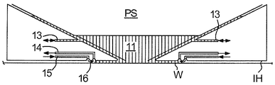
도 2는 투영 시스템(PS)의 최종 요소와 기판 테이블(WT) 또는 기판(W) 사이의 공간(11)의 경계의 적어도 일부분을 따라 연장되는 액체 한정 구조체(IH)를 갖는 국부화된 액체 공급 시스템 또는 유체 핸들링 시스템을 개략적으로 도시한다[다음의 설명에서 기판(W)의 표면에 관한 언급은, 다른 곳에 특별히 언급되지 않는다면, 추가적으로 또는 대안적으로 기판 테이블(WT)의 표면을 칭함을 유의한다]. 일 실시예에서, 액체 한정 구조체(IH)와 기판(W)의 표면 사이에 시일(seal)이 형성된다. 시일은 가스 시일(16)(가스 시일을 갖는 이러한 시스템은 유럽 특허 출원 공개공보 EP-A-1,420,298에 개시됨) 또는 액체 시일과 같은 무접촉 시일일 수 있다.Figure 2 shows a localized liquid supply (not shown) having a liquid confinement structure IH extending along at least a part of the boundary of the
액체 한정 구조체(IH)는 투영 시스템(PS)의 최종 요소와 기판(W) 사이의 공간(11)에 액체를 적어도 부분적으로 수용한다. 공간(11)은 투영 시스템(PS)의 최종 요소 아래에, 그리고 이를 둘러싸서 위치된 액체 한정 구조체(IH)에 의해 적어도 부분적으로 형성된다. 액체 유입구/유출구(13)에 의해 투영 시스템(PS) 아래의 그리고 액체 한정 구조체(IH) 내의 공간(11)으로 액체가 유입된다. 액체는 액체 유입구/유출구(13)에 의해 제거될 수 있다. 일 실시예에서, 2 개의 액체 유입구/유출구(13) 중 하나가 액체를 공급하는 한편, 다른 액체 유입구/유출구(13)는 스캐닝 방향에 따라 액체를 제거한다.The liquid confinement structure IH at least partially contains a liquid in the
액체는 가스 시일(16)에 의해 공간(11)에 수용될 수 있다. 사용 시, 가스 시일(16)은 액체 한정 구조체(IH)의 최하부와 기판(W)의 표면 사이에 형성된다. 가스 시일(16)의 가스는 유입구(15)를 통해 액체 한정 구조체(IH)와 기판(W) 사이의 갭에 압력 하에(under pressure) 제공된다. 가스는 유출구(14)를 통해 추출된다. 가스 유입구(15)의 과대압력(overpressure), 유출구(14)의 진공 레벨 및 갭의 지오메트리(geometry)는 액체를 한정하는 고속의 가스 유동(16)이 안쪽으로 존재하도록 배치된다. 액체 한정 구조체(IH)와 기판(W) 사이의 액체 상에서의 가스의 힘은 공간(11)에 액체를 수용한다. 이러한 시스템은 미국 특허 출원 공개공보 US 2004-0207824에 개시되어 있으며, 본 명세서에서 전문이 인용 참조된다. 일 실시예에서, 액체 한정 구조체(IH)는 가스 시일을 갖지 않는다.The liquid can be received in the
국부화된 영역 액체 공급 시스템에서, 기판(W)은 투영 시스템(PS) 및 액체 공급 시스템 아래로 이동된다. 기판(W)의 에지가 이미징되어야 할 때, 기판(W)(또는 다른 대상물)의 에지가 공간(11) 아래를 지나갈 것이다. 기판 테이블(WT)(또는 측정 테이블)의 센서가 이미징되어야 할 때, 기판(W)(또는 다른 대상물)의 에지가 공간(11) 아래를 지나갈 것이다. 예를 들어, 기판 교체(substrate swap)가 이루어지게 하기 위해 더미 기판(dummy substrate) 또는 소위 클로징 플레이트(closing plate)가 액체 공급 시스템 아래에 위치될 수 있다. 더미 기판 또는 소위 클로징 플레이트가 액체 공급 시스템 아래에 위치될 수 있도록 기판 테이블(WT)이 이동되어야 할 때, 기판(W)(또는 다른 대상물)의 에지가 공간(11) 아래를 지나갈 것이다. 기판(W)과 기판 테이블(WT) 사이의 갭 내로 액체가 누출될 수 있다. 이 액체는 정수압 또는 동수압(hydrostatic or hydrodynamic pressure) 하에서, 또는 가스 나이프(gas knife) 또는 다른 가스 유동 생성 디바이스의 힘 하에서 강제(force)될 수 있다.In the localized area liquid supply system, the substrate W is moved under the projection system PS and the liquid supply system. When the edge of the substrate W is to be imaged, the edge of the substrate W (or other object) will pass under the
도 3은 일 실시예에 따른 또 다른 액체 공급 시스템 또는 유체 핸들링 시스템을 도시하는 측단면도이다. 도 3에 예시되고 아래에 설명되는 구성은 앞서 설명되고 도 1에 예시된 리소그래피 장치(100)에 적용될 수 있다. 액체 공급 시스템에는 투영 시스템(PS)의 최종 요소와 기판 테이블(WT) 또는 기판(W) 사이의 공간(11)의 경계의 적어도 일부분을 따라 연장되는 액체 한정 구조체(IH)가 제공된다[다음의 설명에서 기판(W)의 표면에 관한 언급은, 다른 곳에 특별히 언급되지 않는다면, 추가적으로 또는 대안적으로 기판 테이블(WT)의 표면 또한 칭함을 유의한다].3 is a side cross-sectional view illustrating another liquid supply system or fluid handling system according to one embodiment. The configuration illustrated in FIG. 3 and described below can be applied to the
액체 한정 구조체(IH)는 투영 시스템(PS)의 최종 요소와 기판(W) 사이의 공간(11)에 액체를 적어도 부분적으로 수용한다. 공간(11)은 투영 시스템(PS)의 최종 요소 아래에, 그리고 이를 둘러싸서 위치된 액체 한정 구조체(IH)에 의해 적어도 부분적으로 형성된다. 일 실시예에서, 액체 한정 구조체(IH)는 메인 몸체 부재(main body member: 53) 및 다공성 부재(porous member: 83)를 포함한다. 다공성 부재(83)는 플레이트 형상이고, 복수의 구멍들(즉, 개구부들 또는 다공들)을 갖는다. 일 실시예에서, 다공성 부재(83)는 메시 플레이트(mesh plate)이며, 다수의 작은 구멍들(84)이 메시에 형성된다. 이러한 시스템은 미국 특허 출원 공개공보 US 2010/0045949 A1에 개시되어 있으며, 본 명세서에서 전문이 인용 참조된다.The liquid confinement structure IH at least partially contains a liquid in the
메인 몸체 부재(53)는 공간(11)에 액체를 공급할 수 있는 공급 포트들(72), 및 공간(11)으로부터 액체를 회수할 수 있는 회수 포트(73)를 포함한다. 공급 포트들(72)은 통로(passageway: 74)들을 통해 액체 공급 장치(75)에 연결된다. 액체 공급 장치(75)는 공급 포트들(72)에 액체를 공급할 수 있다. 액체 공급 장치(75)로부터 이송되는 액체는 대응하는 통로(74)를 통해 공급 포트들(72)의 각각에 공급된다. 공급 포트들(72)은 광학 경로와 마주하는 메인 몸체 부재(53)의 규정된 위치들에서 광학 경로의 부근에 배치된다. 회수 포트(73)는 공간(11)으로부터 액체를 회수할 수 있다. 회수 포트(73)는 통로(79)를 통해 액체 회수 장치(80)에 연결된다. 액체 회수 장치(80)는 진공 시스템을 포함하고, 회수 포트(73)를 통해 액체를 빨아들임으로써 액체를 회수할 수 있다. 액체 회수 장치(80)는 통로(29)를 통하여 회수 포트(23)를 통해 회수된 액체(LQ)를 회수한다. 다공성 재료(83)가 회수 포트(73)에 배치된다.The
일 실시예에서, 투영 시스템(PS)과, 일측은 액체 한정 구조체(IH)와의 사이에 그리고 다른 측은 기판(W) 과의 사이에 액체를 갖는 공간(11)을 형성하기 위해, 공급 포트들(72)로부터 공간(11)으로 액체가 공급되고, 액체 한정 구조체(IH)의 회수 챔버(81)의 압력이 부압(negative pressure)으로 조정되어 다공성 부재(83)의 구멍들(84)[즉, 회수 포트(73)]을 통해 액체를 회수한다. 공급 포트들(72)을 이용하는 액체 공급 작동 및 다공성 부재(83)를 이용하는 액체 회수 작동을 수행하는 것은, 투영 시스템(PS)과, 일측은 액체 한정 구조체(IH)와의 사이에 다른 측은 기판(W)과의 사이에 공간(11)을 형성한다.In one embodiment, the projection system PS is connected to the supply ports (not shown) to form a
리소그래피 장치(100)의 사용 시, 기판(W)은 상이한 리소그래피 단계들 및 공정 단계들을 거친다. 예를 들어, 습식 화학 처리(wet chemical treatment)에 의해 기판(W)이 세정될 수 있다. 기판(W)은 기판(W)의 표면에 존재할 수 있는 여하한의 습기를 없애기에(drive off) 충분한 온도로 가열될 수 있다. 기판(W)은 레지스트(예를 들어, 포토레지스트) 층으로 덮일 수 있다. 기판(W)은 과도한 포토레지스트 용매를 없애기 위해 사전베이크(prebake)될 수 있다. 이후, 방사선 빔(B)의 패턴이 기판(W) 상으로 전사되도록 기판(W)이 노광된다. 이후, 기판(W)은 레지스트의 현상, 에칭 및 제거를 거칠 수 있다. 이러한 단계들은 기판(W) 상의 또 다른 층에 대해 반복될 수 있다.In use of the
도 1에 도시된 바와 같이, 일 실시예에서 리소그래피 장치(100)는 기판 테이블(WT)을 포함한다. 기판 테이블(WT)은 노광 공정을 위해 기판(W)을 지지하도록 구성된다. 노광 공정에서, 기판(W)은 액체(즉, 침지 액체)를 통해 기판(W)에 패턴을 형성하도록 방사선 빔(B)에 노광된다. 일 실시예에서, 리소그래피 장치(100)에서 기판(W)을 이송하는 방법이 제공된다. 본 방법은 노광 공정을 위해 기판 테이블(WT) 상에 기판(W)을 지지하는 단계를 포함한다. 노광 공정에서, 방사선 빔(B)의 패턴이 기판(W) 상으로 전사된다.As shown in Figure 1, in one embodiment, the
노광 공정 후 기판(W) 상의 레지스트에 액체, 예를 들어 물의 일부가 남게 된다. 액체는 레지스트를 저하시킬 수 있다. 액체가 남아있다면, 레지스트의 저하는 결함을 유도할 수 있다. 다수의 층들이 각각의 기판(W)에 형성될 수 있다. 단일 층에 발생하는 결함의 확률(probability)이 작더라도, 층들의 수가 많다면, 전체 결함 발생 확률이 매우 클 수 있다.After the exposure process, a portion of the liquid, for example, water, remains in the resist on the substrate W. The liquid may degrade the resist. If a liquid remains, the degradation of the resist can lead to defects. A plurality of layers may be formed in each substrate W. Even if the probability of a defect occurring in a single layer is small, if the number of layers is large, the probability of occurrence of an entire defect can be very large.
일 실시예에서, 리소그래피 장치(100)는 후-노광 핸들링 모듈(94)(도 6에 도시됨)을 포함한다. 후-노광 핸들링 모듈은 기판(W) 후-노광을 핸들링하기 위한 모듈이다. 노광 공정 후, 기판(W)은 후-노광 핸들링 모듈(94)에 의해 핸들링된다. 예를 들어, 일 실시예에서 후-노광 핸들링 모듈(94)은 적어도 하나의 기판 핸들러 센서(51)(이는 웨이퍼 핸들러 센서라고도 칭해질 수 있음)를 포함한다. 적어도 하나의 기판 핸들러 센서(51)는 기판 핸들링 로봇(41)과 연계된 파라미터[예를 들어, 홀더(43)의 위치, 홀더(43)의 경사]를 측정하도록 구성된다. 일 실시예에서, 적어도 하나의 기판 핸들러 센서(51)는 센서 프레임(SF)(도 1에 도시됨)에 장착된다. 센서 프레임(SF)은 메트롤로지 프레임이라고 칭해질 수 있다. 대안적으로, 일 실시예에서 적어도 하나의 기판 핸들러 센서(51)는 리소그래피 장치(100)의 베이스 프레임(BF)(도 1에 도시됨)에 장착된다. 일 실시예에서, 액체 한정 구조체(IH)가 센서 프레임(SF)에 부착된다. 일 실시예에서, 투영 시스템(PS)은 센서 프레임(SF)에 부착된다. 일 실시예에서, 기판 테이블(WT)은 베이스 프레임(BF)에 부착된다. 일 실시예에서, 센서 프레임(SF)은 베이스 프레임(BF)으로부터 동적으로 격리(dynamically isolate)된다. 일 실시예에서, 기판 교체 시 기판 핸들링 로봇(41)의 홀더(43)의 위치 및 경사가 고정된 공차(tolerance) 내에 있는지를 검사하기 위해 적어도 하나의 기판 핸들러 센서(51)가 사용된다.In one embodiment, the
일 실시예에서, 적어도 하나의 기판 핸들러 센서(51)는 하나 이상의(예를 들어, 2 개의) 광학 센서들을 포함한다. 광학 센서들은 Y-축에 대하여 홀더(43)의 경사를 측정하도록 구성된다. 일 실시예에서, 적어도 하나의 기판 핸들러 센서(51)는 하나 이상의(예를 들어, 3 개의) 다른 센서들을 포함한다. 일 실시예에서, 적어도 하나의 기판 핸들러 센서(51)의 다른 센서들은 용량성(capacitive)이다. 적어도 하나의 기판 핸들러 센서(51)의 다른 센서들은 XY 평면에서 홀더(43)의 위치를 측정하도록 구성된다.In one embodiment, at least one
일 실시예에서, 리소그래피 장치(100)는 2 개의 기판 핸들링 로봇들(41)을 포함한다. 일 실시예에서, 리소그래피 장치(100)는 각각의 기판 핸들링 로봇(41)에 연계된 2 개의 기판 핸들러 센서들(51)을 포함한다. 각각의 기판 핸들링 로봇(41)은 연계된 쌍의 기판 핸들러 센서들(51)을 갖는다.In one embodiment, the
도 4는 일 실시예에 따른 리소그래피 장치(100)의 일부분을 개략적으로 도시한다. 일 실시예에서, 리소그래피 장치(100)는 기판 핸들링 로봇(41)을 포함한다. 기판 핸들링 로봇(41)은 기판 테이블(WT)로부터 기판 언로딩 경로를 따라 후-노광 핸들링 모듈(94) 내로 기판(W)을 이송하도록 구성된다. 일 실시예에서, 기판(W)을 이송하는 방법은 기판 테이블(WT)로부터 기판 언로딩 경로를 따라 기판(W) 후-노광을 핸들링하는 후-노광 핸들링 모듈(94) 내로 기판(W)을 이송하는 단계를 포함한다.Figure 4 schematically illustrates a portion of a
도 4에 도시된 바와 같이, 일 실시예에서 기판 핸들링 로봇(41)은 로봇 아암(robot arm: 42)(또는 기판 핸들링 아암)을 포함한다. 일 실시예에서, 기판 핸들링 로봇(41)은 위치설정기 부분(44)(도 6에 도시됨) 및 홀더(43)를 포함한다. 위치설정기 부분(44)은 홀더(43)와 인터페이싱한다(interface). 예를 들어, 위치설정기 부분(44)은 로봇 아암(42)을 통해 홀더(43)와 인터페이싱할 수 있다. 일 실시예에서, 로봇 아암(42)은 위치설정기 부분(44)의 액추에이터들에 의해 구동되고, 후-노광 핸들링 모듈(94) 내의 언로딩 도크(unloading dock)와 기판 테이블(WT) 사이로 기판(W)을 이송하는 데 사용된다.As shown in FIG. 4, in one embodiment, the
일 실시예에서, 홀더(43)는 실질적으로 수평 평면으로 이격된 한 쌍의 프롱(prong)을 포함한다. 일 실시예에서, 프롱들의 각각의 상부면 또는 이의 일부분에는 레이저 소결(laser sintering)에 의해 형성된 버얼(burl)들을 갖는 영역이 제공될 수 있다. 버얼들의 사용은 진공 및 정전기 클램핑 기술들의 사용을 가능하게 하고, 입자들이 기판(W)을 왜곡시키는 것을 방지한다.In one embodiment, the
일 실시예에서, 리소그래피 장치(100)는 건조 스테이션(90)을 포함한다. 건조 스테이션(90)은 기판(W)의 표면(46)으로부터 액체를 능동적으로 제거하도록 구성된다. 예를 들어, 침지 액체의 액적(droplet: 50)이 기판(W)의 표면(46)에 존재할 수 있다. 건조 스테이션(90)은 기판(W)의 표면(46)으로부터 액적(50)을 능동적으로 제거하도록 구성된다. 건조 스테이션(90)은 기판(W)의 표면(46)으로부터 액막(liquid film)을 능동적으로 제거하도록 구성된다.In one embodiment, the
일 실시예에서, 건조 스테이션(90)은 기판 언로딩 경로에 위치된다. 특히, 기판(W)이 기판 언로딩 경로를 따라 이송 시 건조 스테이션(90)을 완전히 통과할 수 있도록, 건조 스테이션(90)은 기판 언로딩 경로에 위치된다. 기판(W)은 기판 언로딩 경로에서 건조될 수 있다. 본 발명의 일 실시예는 기판 테이블(WT)과 후-노광 핸들링 모듈(94) 사이의 기판 언로딩 경로로부터 기판(W)을 벗어나게 하지 않고 기판(W)의 건조를 달성할 것으로 예상된다.In one embodiment, the drying
기판(W)이 기판 언로딩 경로를 따라 이송 시 건조 스테이션(90)을 완전히 통과할 수 있다면, 건조가 이루어질 특정 위치(예를 들어, 홀딩 테이블)가 반드시 제공될 필요는 없다. '기판(W)이 건조 스테이션(90)을 완전히 통과할 수 있다면'이라는 것은, 건조 스테이션(90) 너머의 기판 언로딩 경로에 기판(W)이 들어맞는(fit) 충분한 공간이 존재함을 의미한다. 이는, 기판(W)과 건조 스테이션(90) 사이의 후속 상대 동작[예를 들어, 기판(W)의 회전]은 기판(W)의 표면(46)이 건조되게 하는, 기판(W)이 건조 스테이션(90) 아래를 부분적으로 통과하는 경우가 아니다. 대신, 기판(W)이 기판 언로딩 경로를 따라 이송되는 과정 동안 기판(W)이 건조될 수 있도록, 기판(W)이 건조 스테이션(90)을 완전히 통과할 수 있다.If the substrate W can pass completely through the drying
일 실시예에서, 건조 스테이션(90)은 후-노광 핸들링 모듈(94)에 위치된다. 기판 언로딩 경로는 기판 테이블(W)의 에지로부터 후-노광 핸들링 모듈(94) 내의 일 위치로 연장된다. 기판 언로딩 경로의 일부분은 후-노광 핸들링 모듈(94) 내에 있다. 일 실시예에서, 건조 스테이션(90)은 후-노광 핸들링 모듈(94) 내에 있는 기판 언로딩 경로의 일부분에 위치된다. 액체의 능동 제거는 기판 언로딩 경로 및 후-노광 핸들링 모듈(94)에서 수행된다.In one embodiment, the drying
일 실시예에서, 후-노광 핸들링 모듈(94)은 기판 핸들러(이는 웨이퍼 핸들러라고도 칭해질 수 있음)이다. 건조 스테이션(90)의 타입은 특정적으로 제한되지 않는다. 건조 스테이션(90)이 기판 핸들러에 위치되면, 본 발명의 일 실시예는 노광된 기판들(W)의 개선된 스루풋을 달성할 것으로 예상된다. 일 실시예에서, 건조 스테이션(90)은, 예를 들어 기판 핸들러에 위치됨에 의하여, 스루풋을 유지하도록 구성된다.In one embodiment, the
건조 스테이션(90)은 웨이퍼 건조기라고도 칭해질 수 있다. 일 실시예에서, 건조 스테이션(90)은 기판(W)이 기판 테이블(WT)(예를 들어, 웨이퍼 테이블)을 빠져나가는 곳 부근에서 기판 핸들러에 있다. 일 실시예에서, 건조 스테이션(90)은 기판(W)이 기판 테이블(WT)을 빠져나가는 곳 부근에서 기판 핸들러 바로 내부에 있다.The drying
일 실시예에서, 건조 스테이션(90)은 가스 나이프(91), 워터 배스(water bath) 및 액체 연속 유동(continuous flow of liquid) 중 하나 이상을 포함한다. 도 4는 가스 나이프(91)를 포함하는 건조 스테이션(90)을 도시한다.In one embodiment, the drying
도 5는 액체 연속 유동[워터라인(waterline)이라고도 칭해질 수 있음]을 포함하는 건조 스테이션(90)을 도시한다. 도 5에 도시된 바와 같이, 일 실시예에서 건조 스테이션(90)은 유동 공급 개구부(92) 및 유동 추출 개구부(93)를 포함한다. 유동 공급 개구부(92)는 건조 스테이션(90)과 기판(W)의 표면(46) 사이의 공간에 액체, 예를 들어 물의 유동을 공급하도록 구성된다. 유동 추출 개구부(93)는 건조 스테이션(90)과 기판(W)의 표면(46) 사이의 공간으로부터 액체, 예를 들어 물을 추출하도록 구성된다.Figure 5 shows a drying
유동 공급 개구부(92) 및 유동 추출 개구부(93)는 건조 스테이션(90)과 기판(W)의 표면(46) 사이의 공간에 연속 액체 유동을 제공하도록 구성된다. 연속 액체 유동은 워터라인 또는 워터 배스라고 칭해질 수 있다. 기판(W)의 표면(46)과 접촉하는 액체의 유동은 액적(50)보다 크다. 액체의 유동이 액적(50)과 접촉하게 될 때, 액적(50)은 액체의 유동의 일부분이 된다. 표면 장력에 의해, 액적(50)은 기판(W)의 표면(46)으로부터 능동적으로 제거된다.The
일 실시예에서, 건조 스테이션(90)은 기판(W)의 표면(46)으로부터 액체만을 추출하는 액체 추출기[단상 추출기(single phase extractor)라고 칭해질 수 있음]를 포함한다. 대안적으로, 일 실시예에서 건조 스테이션(90)은 기판(W)의 표면(46)으로부터 액체와 가스 둘 모두들 추출하는 2-상 추출기(two phase extractor)를 포함한다.In one embodiment, the drying
건조 스테이션(90)이 액체 배스를 포함하는 경우, 액체 배스는 앞서 설명된 바와 같은 액체 한정 구조체(IH)의 구성과 유사한 구성에 의해 제공될 수 있다. 사용 시, 건조 스테이션(90)의 액체 추출기와 기판(W) 사이의 갭이 물로 채워지도록 (물과 같은) 액체가 기판(W)에 공급된다. 기판(W)과 액체 추출기 사이의 갭이 항상 물로 채워질 것을 보장하기 위해 건조 공정 동안 물이 계속 제공된다. 갭을 채우는 물은 워터 배스라고 칭해질 수 있다. 기판으로부터 제거되는 액체와 건조 스테이션(90)에 의해 공급되는 물은 단일 몸체의 액체(single body of liquid)(즉, 워터 배스)가 된다. 액체 추출기는 기판(W)과 건조 스테이션(90) 사이의 갭으로부터 물을 추출한다. 워터 배스는 기판(W)과 액체 추출기 사이의 갭을 그 자체로 메우기에(span) 충분하지 않은 두께를 갖는 액체를 액체 추출기가 추출하게 한다. 워터 배스의 사용은, 기판(W)의 표면(46)으로부터 제거되는 액체의 두께가 액체 추출기에 도달하기에 충분히 높지 않더라도, 기판(W)과 액체 추출기 사이의 갭이 채워지는 것을 보장하도록 돕는다.If the drying
일 실시예에서, 건조 스테이션(90)은 기판(W)의 표면(46)으로부터 액체를 제거하는 가스 나이프를 포함한다.In one embodiment, the drying
일 실시예에서, 건조 스테이션은 기판(W)의 표면(46)을 가열하도록 구성되는 가열기를 포함한다. 기판(W)의 표면(46) 상의 액체가 가열되고, 기판(W)의 표면(46)으로부터 증발한다.In one embodiment, the drying station includes a heater configured to heat the
일 실시예에서, 건조 스테이션(90)은 건조 스테이션 아암(drying station arm) 및 로테이터(rotator)의 형태를 갖는다. 건조 스테이션 아암은 기판(W)의 표면(46)으로부터 액체를 능동적으로 제거하도록 구성된다. 로테이터는 기판(W)의 표면(46)에 평행한 회전 평면을 통해 건조 스테이션 아암을 회전시키도록 구성된다. 건조 스테이션 아암 및 로테이터는 도 11 및 도 13에 도시되어 있으며, 이후 자세히 설명된다.In one embodiment, the drying
일 실시예에서, 리소그래피 장치(100)는 도 11에 도시된 바와 같이 기판(W)을 회전시키도록 구성되는 기판 턴테이블(substrate turntable: 120)을 포함한다. 일 실시예에서, 건조 스테이션(90)은 기판 턴테이블(120)의 반경에 걸쳐 연장되는 건조 스테이션 아암의 형태를 가져, 기판(W)이 기판 턴테이블(120) 상에서 회전될 때 건조 스테이션 아암이 기판(W)의 표면(46)으로부터 액체를 능동적으로 제거하도록 구성된다.In one embodiment, the
일 실시예에서, 기판 언로딩 경로는 실질적으로 직선이다. 기판 언로딩 경로가 실질적으로 직선이면, 기판 언로딩 경로를 따른 기판 핸들링 로봇(41)의 직선 라인 이동은 기판(W)이 건조 스테이션(90)을 통과하게 한다. 건조 스테이션(90)이 기판(W)의 표면으로부터 액체를 능동적으로 제거한다. 기판(W)은 기판 테이블(WT)로부터 기판 핸들링 모듈(94) 내로 직접적으로 이동될 수 있다. 기판(W)은 직접 이동 시 건조될 수 있다. 건조 스테이션(90)으로 또는 건조 스테이션(90)으로부터 기판(W)을 이동시키는 시간이 낭비되지 않는다. 기판(W)이 기판 언로딩 경로를 따라 직선 라인으로 이송될 때, 건조 스테이션(90)이 기판(W)의 표면(46)으로부터 액체를 능동적으로 제거하도록 기판(W)이 건조 스테이션(90)을 통과한다. 본 발명의 일 실시예는 증가된 스루풋을 달성할 것으로 예상된다.In one embodiment, the substrate unloading path is substantially straight. The straight line movement of the
하지만, 기판 언로딩 경로가 반드시 실질적으로 직선일 필요는 없다. 일 실시예에서, 기판 언로딩 경로는 곡선이다. 기판 언로딩 경로가 곡선이면, 리소그래피 장치(100) 내의 다른 구성요소들의 레이아웃(layout)이 덜 제약된다.However, the substrate unloading path does not necessarily have to be substantially straight. In one embodiment, the substrate unloading path is a curve. If the substrate unloading path is curved, the layout of the other components in the
앞서 언급되고 도 6에 도시되는 바와 같이, 일 실시예에서 기판 핸들링 로봇(41)은 위치설정기 부분(44) 및 위치설정기 부분(44)과 인터페이싱하는 홀더(43)를 포함한다. 홀더(43)는 기판(W)을 유지하도록 구성된다. 일 실시예에서, 홀더(43)는 기판(W)을 잡도록 구성되는 그리퍼(gripper)를 포함한다. 예를 들어, 그리퍼는 기판(W)의 에지들을 잡을 수 있다. 대안적인 실시예에서, 홀더(43)는 기판(W)을 클램핑하도록 구성되는 클램프를 포함한다. 예를 들어, 클램프는 밑으로부터 기판(W)을 클램핑할 수 있다. 클램프는 진공 패드들을 포함할 수 있거나, 정전기 클램프일 수 있다. 위치설정기 부분(44)은 기판 핸들링 로봇(41)의 리스트(wrist)라고 칭해질 수 있다. 위치설정기 부분(44)은 로봇 언로드 위치와 로봇 핸들링 위치 사이에서 이동하도록 구성된다. 로봇 언로드 위치에서, 홀더(43)는 기판 테이블(WT) 상에 기판(W)을 유지한다. 로봇 핸들링 위치에서, 홀더(43)는 후-노광 핸들링 모듈(94)에 기판(W)을 유지한다. 도 4 및 도 5에서, 위치설정기 부분(44)(도 4 또는 도 5에 도시되지 않음)은 로봇 언로드 위치와 로봇 핸들링 위치 사이의 일 위치에 있다.6, the
기판(W)의 노광 후, 위치설정기 부분(44)은 로봇 언로드 위치에 있고, 홀더(43)는 기판(W)을 유지한다. 기판(W)은 기판 테이블(WT)로부터 제거된다. 위치설정기 부분(44)은 로봇 언로드 위치로부터 로봇 핸들링 위치로 이동한다. 일 실시예에서, 위치설정기 부분(44)은 기판 언로딩 경로를 따라 이동한다. 일 실시예에서, 로봇 핸들링 위치는 후-노광 핸들링 모듈(94) 내에 있다.After exposure of the substrate W, the
기판 테이블(WT)의 에지는 기판 언로딩 경로의 상류 단부에 있다. 기판 언로딩 경로의 하류 단부는 후-노광 핸들링 모듈(94) 내에 있다. 일 실시예에서, 건조 스테이션(90)은 로봇 언로드 위치 상류의 기판 언로딩 경로에 위치된다. 위치설정기 부분(44)은 건조 스테이션(90)을 지나 이동하지 않는다. 위치설정기 부분(44)이 기판 테이블(WT)을 향해 이동할 때, 위치설정기 부분(44)은 건조 스테이션(90)에 도달하지 않는다. 위치설정기 부분(44)이 건조 스테이션(90)에 도달하지 않으면, 건조 스테이션(90)은 위치설정기 부분(44)의 이동 범위 밖에 있다. 건조 스테이션(90)은 기판 핸들링 로봇(41)의 위치설정기 부분(44)의 이동을 방해하지 않는다.The edge of the substrate table WT is at the upstream end of the substrate unloading path. The downstream end of the substrate unloading path is within the
일 실시예에서, 기판(W)은 기판 핸들링 로봇(41)에 의해 실질적으로 수평으로 이동된다. 일 실시예에서, 기판(W)이 이송되고 있을 때, 홀더(43)는 기판(W) 아래에 있다. 일 실시예에서, z-방향으로의 위치설정기 부분(44)의 높이는 z-방향으로의 홀더(43)의 높이보다 높다. 일 실시예에서, 위치설정기 부분(44)의 최상부는 기판(W)의 표면(46)보다 높다. 일 실시예에서, 위치설정기 부분(44)의 최상부는 건조 스테이션(90)의 최하부보다 높다. 건조 스테이션(90)이 위치설정기 부분(44)의 이동 범위 내에 있는 경우, 건조 스테이션(90)은 위치설정기 부분의 이동을 잠재적으로 방해할 수 있다. 건조 스테이션(90)이 로봇 언로드 위치 상류의 기판 언로딩 경로에 위치되면, 건조 스테이션(90)은 위치설정기 부분(44)의 이동 범위 밖에 있다. 건조 스테이션(90)은 기판 핸들링 로봇(41)의 위치설정기 부분(44)의 이동을 방해하지 않는다.In one embodiment, the substrate W is moved substantially horizontally by the
일 실시예에서, 건조 스테이션(90)은 로봇 언로드 위치에 인접하게 위치된다. 건조 스테이션(90)이 로봇 언로드 위치에 인접하게 위치되면, 건조 스테이션(90)은 기판 핸들링 로봇(41)의 이동을 방해하지 않고 기판 테이블(WT)에 가능한 한 가까울 수 있다. 본 발명의 일 실시예는 스루풋에 부정적인 영향을 주지 않고 가능한 한 빨리 기판(W)의 표면(46)으로부터 액체의 제거를 달성할 것으로 예상된다. 액체, 예를 들어 물을 가능한 한 빨리 기판(W)으로부터 소멸시키는 것이 바람직하다.In one embodiment, the drying
건조기라고 칭해질 수 있는 건조 스테이션(90)은, 기계, 즉 리소그래피 장치(100)의 스루풋에 영향을 주지 않고, 또한 스테이지, 예를 들어 기판 테이블(WT)로부터 기판(W)의 언로딩 후 기판(W)으로부터 액체를 가능한 한 빨리 제거한다. 건조 스테이션(90)은 기판(W)이 언로딩되는 위치에 가능한 한 근접하게 위치되는 것이 바람직하다. 기판 핸들링 로봇(41)의 이동은 건조 스테이션(90)의 유체 유동 하에서 기판(W)의 표면(46)을 인출(draw)하는 것이 바람직하다. 액적(50)을 가능한 한 빨리 제거함으로써, 물 액적에 대한 레지스트의 노출 시간이 최소화되어, 결함 발생의 위험성을 감소시킨다. 일 실시예에서, 건조 스테이션(90)은 기판 핸들러(이는 웨이퍼 핸들러라고도 칭해질 수 있음) 내에 있다.A drying
건조 스테이션(90)의 형태는 실현가능하다면 어떤 것도 가능할 수 있다. 앞서 설명되고 도 4 및 도 5에 도시된 두 가지 타입은 단순한 건조 스테이션(90)의 예시들이다.The configuration of the drying
건조 스테이션(90)은 기판 핸들러와 연계되며, 이는 이것이 기판 테이블(W)과 함께, 예를 들어 기판 테이블(WT)에 또는 기판 테이블(WT) 위에 있으면 스루풋에 부정적인 영향을 줄 것이기 때문이다. 이는, 노광 공정 후, 기판(WT)을 건조시키기 위해 웨이퍼 스테이지에 추가 시간이 요구될 것이기 때문이다. 기판(W)이 건조되고 있을 때, 기판(W)은 다른 때보다 더 느리게 이동된다. 건조 스테이션(90)이 웨이퍼 스테이지[예를 들어, 액체 한정 구조체(IH) 또는 기판 테이블(WT)]에 있다면, 기판(W)은 기판(W)을 건조시키기 위해 기판 테이블(WT)로부터 느리게 제거되어야 할 필요가 있을 것이다. The drying
건조 스테이션(90)이 후-노광 핸들링 모듈(94)에 있으면, 기판(W)이 기판 테이블(WT)로부터 더 빨리 제거될 수 있다. 다음 노광 공정을 위해 후속 기판(W)이 기판 테이블(WT) 상에 더 빨리 로딩될 수 있다. 본 발명의 일 실시예는 리소그래피 장치(100)의 스루풋의 개선을 달성할 것으로 예상된다.If the drying
일 실시예에서, 후-노광 핸들링 모듈(94)은 적어도 하나의 기판 핸들러 센서(51)를 포함한다. 예를 들어, 기판 핸들러 센서(51)는 기판 교환 센서(웨이퍼 교환 센서라고 칭해질 수 있음)일 수 있다. 적어도 하나의 기판 핸들러 센서(51)는 기판 핸들링 로봇(41)과 연계된 파라미터를 측정하도록 구성된다. 예를 들어, 일 실시예에서 적어도 하나의 기판 핸들러 센서(51)는 XY-평면에 대한 기판 핸들링 로봇(41)의 홀더(43)의 경사를 측정하도록 구성된다. 일 실시예에서, 적어도 하나의 기판 핸들러 센서(51)가 기판 언로딩 경로에 위치된다. 일 실시예에서, 적어도 하나의 기판 핸들러 센서(51)는 기판(W)이 노광 공정 후 기판 테이블(WT)로부터 이송될 때 측정을 수행한다.In one embodiment, the
일 실시예에서, 건조 스테이션(90)은 적어도 하나의 기판 핸들러 센서(51) 부근에 위치된다. 일 실시예에서, 건조 스테이션(90)은 기판 교환 센서에/기판 교환 센서 부근에 위치된다. 일 실시예에서, 건조 스테이션(90)은 적어도 하나의 기판 핸들러 센서(51)에 인접하게 위치된다. 일 실시예에서, 적어도 하나의 기판 핸들러 센서(51)는 센서 프레임(SF)에 부착된다. 센서 프레임(SF)은 기판 언로딩 경로에 위치된다. 일 실시예에서, 건조 스테이션(90)은 로봇 언로드 위치와 센서 프레임(SF) 사이에 위치된다. 일 실시예에서, 건조 스테이션(90)은 센서 프레임(SF)에 고정된다. 건조 스테이션(90)이 센서 프레임(SF)에 고정되면, 건조 스테이션(90)에 의해 차지되는 공간이 최소화된다.In one embodiment, drying
일 실시예에서, 건조 스테이션(90)은 리소그래피 장치(100)의 베이스 프레임(BF)과 적어도 하나의 기판 핸들러 센서(51) 사이에 위치된다. 일 실시예에서, 베이스 프레임(BF)은 에어 덕트(air duct)를 포함한다. 일 실시예에서, 건조 스테이션(90)은 에어 덕트와 적어도 하나의 기판 핸들러 센서(51) 사이에 위치된다.In one embodiment, the drying
일 실시예에서, 건조 스테이션(90)은 기판(W)의 폭보다 큰 폭을 갖는다. 예를 들어, 기판(W)의 폭이 약 300 mm인 경우, 건조 스테이션(90)은 약 300 mm보다 큰 폭, 예를 들어 320 mm의 폭을 갖는다. 기판(W)의 폭이 약 450 mm인 경우, 건조 스테이션(90)은 약 450 mm보다 큰 폭을 가질 수 있다. 건조 스테이션(90)은 기판(W)의 표면(46)의 전체로부터 액체를 능동적으로 제거할 수 있다. 건조 스테이션(90)은, 기판(W)이 건조 스테이션(90) 밑을 통과할 때 기판(W)의 표면(46)으로부터 액체를 능동적으로 제거한다.In one embodiment, the drying
일 실시예에서, 건조 스테이션(90)은 폭, 길이 및 높이를 갖는다. 일 실시예에서, 건조 스테이션(90)은 폭이 길이 또는 높이보다 크도록 신장된다(elongate). 일 실시예에서, 폭은 약 300 mm보다 크거나, 약 450 mm보다 크다. 예를 들어, 일 실시예에서 건조 스테이션(90)의 폭은 약 320 mm이다. 일 실시예에서, 길이는 약 50 mm 미만, 예를 들어 약 20 mm이다. 일 실시예에서, 높이는 약 50 mm 미만, 예를 들어 약 30 mm이다.In one embodiment, the drying
일 실시예에서, 리소그래피 장치(100)는 후-노광 핸들링 모듈(94)과 인터페이싱하는 노광 모듈(95)을 포함한다. 기판 테이블(WT)은 노광 모듈(95)에 있다. 액체 한정 구조체(IH)는 노광 모듈(95)에 있다. 일 실시예에서, 건조 스테이션(90)은 노광 모듈(95)과 후-노광 핸들링 모듈(94) 사이의 계면에 또는 그 부근에 위치된다.In one embodiment, the
노광 모듈(95)에서 기판(W)을 건조시키는 시간이 낭비되지 않도록, 건조 스테이션(90)은 노광 모듈(95)에 위치되지 않는다. 본 발명의 일 실시예는 노광 모듈(95)을 통해 기판들(W)의 증가된 스루풋을 달성할 것으로 예상된다.The drying
건조 스테이션(90)이 기판 테이블(W)에 가능한 한 가깝게 위치되도록, 건조 스테이션(90)은 노광 모듈(95)과 후-노광 핸들링 모듈(94) 사이의 계면 부근에 위치된다. 건조 스테이션(90)이 기판 테이블(W)에 가능한 한 근접하게 위치되면, 액적(50)이 기판(W)의 표면(46)에 남아 있는 시간이 최소화된다.The drying
후-노광 핸들링 모듈(94) 내의 건조 스테이션(90)의 위치는 리소그래피 장치(100)의 다른 구성요소들과의 공간 충돌을 최소화하도록 선택될 수 있다. 일 실시예에서, 건조 스테이션(90)은 노광 모듈(95)과 후-노광 핸들링 모듈(94) 사이의 계면으로부터 이격된다.The location of the drying
일 실시예에서, 건조 스테이션(90)은 건조 스테이션 액추에이터(45)(도 6에 도시됨)를 포함한다. 건조 스테이션 액추에이터(45)는 리소그래피 장치(100)의 정지 구성요소들에 대해 건조 스테이션(90)을 위아래로 이동시키도록 구성된다. 예를 들어, 일 실시예에서 기판 핸들러 센서(51)는 리소그래피 장치(100)의 사용 시 정지해 있다. 건조 스테이션 액추에이터(45)는 기판 핸들러 센서(51)에 대해 건조 스테이션(90)을 위아래로 이동시키도록 구성된다. 일 실시예에서, 건조 스테이션 액추에이터(45)는 기판(W)에 대해 건조 스테이션(90)을 위아래로 이동시키도록 구성된다. 건조 스테이션 액추에이터(45)는 건조 위치와 비-건조 위치 사이로 건조 스테이션(90)을 이동시키도록 구성된다. 건조 위치에서, 건조 스테이션(90)은 기판(W)의 표면(46)으로부터 액체를 능동적으로 제거한다.In one embodiment, the drying
건조 스테이션 액추에이터(45)를 제공함으로써, 기판 핸들링 로봇(41)이 건조 위치를 통해 이동하더라도, 건조 스테이션(90)은 기판 핸들링 로봇(41)의 이동을 방해하지 않을 건조 위치를 가질 수 있다. 앞서 언급된 바와 같이, 일 실시예에서, 기판 핸들링 로봇(41)의 위치설정기 부분(44)이 건조 스테이션(90)에 도달하지 않아, 건조 스테이션(90)이 위치설정기 부분(44)의 이동 범위 밖에 있다. 이에 따라, 건조 스테이션(90)은 기판 핸들링 로봇(41)의 위치설정기 부분(44)의 이동을 방해하지 않는다. 하지만, 건조 스테이션 액추에이터(45)를 제공함으로써, 기판 핸들링 로봇(41)이 X-Y 평면에서 건조 스테이션(90)에 도달하더라도, 건조 스테이션(90)은 기판 핸들링 로봇(41)의 위치설정기 부분(44)의 이동을 방해하지 않는다. 비-건조 위치에서, 건조 스테이션(90) 및 기판 핸들링 로봇(41)이 z-방향으로 상이한 위치들을 갖기 때문에, 건조 스테이션(90)은 기판 핸들링 로봇(41)의 이동을 방해하지 않는다. 기판 핸들링 로봇(41)이 X-Y 평면에서 건조 스테이션(90)에 도달하는 일 실시예에서는, 기판 핸들링 로봇(41)의 위치설정기 부분(44)이 건조 스테이션(90)을 통과할 때, 건조 스테이션(90)은 비-건조 위치에 있다. 위치설정기 부분(44)이 건조 스테이션(90)을 통과한 후, 건조 스테이션 액추에이터(45)는 건조 스테이션(90)을 건조 위치로 이동시킬 수 있다. 기판(W)이 건조 스테이션(90)을 통과할 때, 건조 스테이션(90)은 건조 위치에 있다.By providing the drying
일 실시예에서, 기판(W)을 이송하는 방법은 건조 스테이션(90)이 기판(W)의 표면(46)으로부터 액체를 능동적으로 제거하는 건조 위치와 비-건조 위치 사이에서 [리소그래피 장치(100)의 정지 구성요소들에 대해] 건조 스테이션(90)을 위아래로 이동시키는 단계를 포함한다.In one embodiment, a method of transferring a substrate W is performed between a dry and a non-dry position in which the drying
일 실시예에서, 기판 핸들링 로봇(41)은 기판(W)이 건조 스테이션(90)을 통과할 때 기판 언로딩 경로를 지나가는 기판(W)의 속력을 감소시키도록 구성된다. 속력의 감소가 스루풋을 저하시킬 수 있지만, 더 높은 비율의 액체가 기판(W)의 표면(46)으로부터 제거될 수 있다. 일 실시예에서, 기판(W)이 건조 스테이션(90)을 통과할 때, 기판(W)은 기판 언로딩 경로를 지나가는 감소된 속력으로 이송된다. 예를 들어, 기판 핸들링 로봇(41)은 기판(W)이 건조 스테이션(90)을 통과할 때 약 1ms-1의 속력으로 기판(W)을 이송할 수 있다. 속력을 감소시킴으로써, 기판(W)이 건조 스테이션(90)을 통과할 때 더 높은 비율의 액체가 기판(W)의 표면(46)으로부터 제거될 수 있다.In one embodiment, the
건조 위치에서, 밑을 통과하는 기판(W)과 건조 스테이션(90) 사이의 거리는 가능한 한 작은 것이 바람직하다. 일 실시예에서, 거리는 약 10 mm 미만, 또한 바람직하게는 약 5 mm 미만이다. 일 실시예에서, 거리는 약 1 mm 미만, 예를 들어 약 0.3 mm이다.In the drying position, the distance between the substrate W passing under the drying
일 실시예에서, 건조 스테이션(90)은 적어도 하나의 기판 핸들러 센서(51) 부근에 위치된다. 건조 스테이션(90)의 위치는 기판 핸들러 센서(51)가 위치되는 영역 내에 있다. 일 실시예에서, 건조 스테이션(90)은 리소그래피 장치(100)의 고정된 구성요소에 연결된다. 예를 들어, 일 실시예에서 건조 스테이션(100)은 도 1에 도시된 베이스 프레임(BF)에 연결된다.In one embodiment, drying
일 실시예에서, 건조 스테이션(90)은 리소그래피 장치(100) 내에 고정된 위치를 갖는다. 이러한 실시예에서, 건조 스테이션(90)은 리소그래피 장치(100)의 사용 중에 또는 건조 스테이션(90)의 사용 중에 이동하지 않는다. 리소그래피 장치(100)의 사용 시, 건조 스테이션(90)이 기판(W)의 표면으로부터 액체를 능동적으로 제거하도록, 기판 핸들링 로봇(41)은 기판 테이블(WT)로부터 건조 스테이션(90) 아래로 기판(W)을 이송한다. 건조 스테이션(90)은 기판(W)과 건조 스테이션(90) 사이에 정의된 거리를 생성하기 위해 공기정압 베어링(aerostatic bearing)을 갖는다. 기판(W)이 건조 스테이션(90) 아래를 이동할 때, 기판(W)의 표면으로부터 액체가 능동적으로 제거된다.In one embodiment, the drying
일 실시예에서, 건조 스테이션(90)은 기판 센서가 위치되는 영역에 있고, 건조 스테이션(90)은 건조 스테이션 액추에이터(45)에 의해 수직 방향으로 가동된다. 건조 스테이션 액추에이터(45)는 도 6과 관련하여 앞서 설명된다. 기판 센서는 기판(W)과 연계된 파라미터(예를 들어, 높이)를 측정하도록 구성된다. 기판 핸들러 센서(51)는 기판 센서로서 사용될 수 있다. 대안적으로, 기판 센서는 기판 핸들러 센서(51)와 별도의 센서일 수 있다. 기판 센서는 기판 테이블(WT)과 건조 스테이션(90) 사이에 위치된다. 기판(W)이 기판 테이블(WT)로부터 언로딩될 때, 기판(W)이 건조 스테이션(90)을 통과하기 전에, 기판(W)이 기판 센서를 통과한다. 일 실시예에서, 기판 센서는 기판(W)의 높이를 측정하도록 구성된다. 일 실시예에서, 건조 스테이션(90)은 기판 센서에 의해 수행된 높이 측정에 기초하여 건조 스테이션 액추에이터(45)에 의해 가동된다. 일 실시예에서, 건조 스테이션 액추에이터(45)는 기판 센서에 의해 수행된 높이 측정에 기초하여 제어된다. 건조 스테이션(90)은 기판(W)과 건조 스테이션(90) 사이의 정의된 거리를 생성하기 위해 공기정압 베어링을 갖는다. 건조 스테이션(90)이 수직 방향으로 가동되지만, 건조 스테이션(90)은 수평 방향으로 정지해 있다. 기판(W)이 건조 스테이션(90) 아래를 이동할 때, 기판(W)으로부터 액체가 능동적으로 제거된다.In one embodiment, the drying
일 실시예에서, 기판 핸들링 로봇(41)의 홀더(43)는 기판(W)의 평탄도(flatness)를 증가시키는 형상을 갖는다. 홀더(43)는 기판(W)의 비평탄도에 대해 기계적 지지를 제공한다. 예를 들어, 일 실시예에서 홀더(43)는 기판(W)의 평면에서 기판을 위한 기계적 지지를 더 광역적으로(extensively) 제공하기 위해 수평 방향으로 연장되는 망형 버팀대들(network of struts: 140)을 포함한다. 버팀대들은 도 14에 도시되어 있다.In one embodiment, the
도 7은 일 실시예에 따른 리소그래피 장치(100)를 개략적으로 도시한다. 도 7에 도시된 바와 같이, 일 실시예에서 리소그래피 장치(100)는 후-침지 헹굼 모듈(post immersion rinse module: 96)을 포함한다. 후-침지 헹굼 모듈(96)은 후-노광 핸들링 모듈(94)과 인터페이싱한다. 후-침지 헹굼 모듈(96)은 후-침지 헹굼 스테이션(도시되지 않음)을 포함한다. 후-침지 헹굼 모듈(96)에서, 예를 들어 후-침지 헹굼 스테이션에서, 기판(W)의 표면으로부터 바람직하지 않은 워터 마크(water mark)들이 제거될 수 있다. 바람직하지 않은 워터 마크들은 기판(W)에 프린트되는 구조체들을 손상시킬 수 있다. 그러므로, 워터 마크들은 제품 수율에 바람직하지 않은 영향을 줄 수 있다. 바람직하지 않은 워터 마크들은 노광 공정 후 기판(W)의 표면에 남아 있는 침지 액체와 같은 액체들에 의해 야기될 수 있다.Figure 7 schematically depicts a
도 8은 일 실시예에 따른 리소그래피 장치(100)를 도시한다. 도 8에 도시된 바와 같이, 일 실시예에서 후-노광 핸들링 모듈(94)은 저장 유닛(110)을 포함한다. 저장 유닛(110)은 복수의 기판(W)들을 저장하도록 구성된다. 저장 유닛(110)은 복수의 기판 수용 유닛(substrate accommodation unit)들을 포함한다. 기판들(W)은 저장 유닛(110)의 각각의 기판 수용 유닛들에 저장될 수 있다.Figure 8 illustrates a
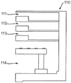
도 9는 일 실시예에 따른 리소그래피 장치(100)의 저장 유닛(110)을 개략적으로 도시한다. 도 9에 도시된 바와 같이, 일 실시예에서 저장 유닛(100)은 기판 수용 유닛들 중 하나로서 상부 클로징 기판 수용 유닛(upper closing substrate accommodation unit: 111)을 포함한다. 상부 클로징 기판 수용 유닛(111)은 클로징 기판을 저장 또는 수용하도록 구성된다. 일 실시예에서, 저장 유닛(110)은 기판 수용 유닛들 중 하나로서 하부 클로징 기판 수용 유닛(112)을 포함한다. 하부 클로징 기판 수용 유닛(112)은 클로징 기판을 저장 또는 수용하도록 구성된다. 일 실시예에서, 저장 유닛(110)은 클로징 기판들을 저장하기 위해, 0 개, 1 개 또는 2 개 이상의 기판 수용 유닛들을 포함한다.Figure 9 schematically illustrates a
클로징 기판은 상이한 기판들(W)의 노광 공정들 사이의 시간 주기 동안에 리소그래피 장치(100)의 일부분의 온도를 안정화하는 데 사용될 수 있다. 예를 들어, 한 뱃치(batch)의 기판들(W)이 노광 공정들에 노광될 수 있다. 후속 뱃치의 기판들(W)이 노광되기 전에, 클로징 기판이 온도 안정화를 위해 기판 테이블(WT)에 위치될 수 있다. 예를 들어, 클로징 기판은 기판 테이블(WT)의 온도를 안정화하도록 도울 수 있다. 일 실시예에서, 기판(W)은 후-침지 헹굼 모듈(96)로부터 최하부 수용 유닛(114) 내로 로딩될 수 있다.The closing substrate can be used to stabilize the temperature of a portion of the
도 9에 도시된 바와 같이, 일 실시예에서 저장 유닛(110)은 기판 수용 유닛들 중 하나로서 방출 유닛(discharge unit: 113)을 포함한다. 방출 유닛(113)은 기판(W)이 노광 공정에서 노광된 후 기판(W)을 수용하도록 구성된다. 일 실시예에서, 기판 핸들링 로봇(41)은 기판 테이블(WT)로부터 방출 유닛(113)으로 노광된 기판(W)을 운송하도록 구성된다. 일 실시예에서, 노광된 기판(W)은 후속하여 방출 유닛(113)으로부터 후-침지 헹굼 모듈(96)로 운송된다.As shown in FIG. 9, in one embodiment, the
도 9에 도시된 바와 같이, 일 실시예에서 저장 유닛(110)은 기판 수용 유닛들 중 하나로서 최하부 수용 유닛(114)을 포함한다. 일 실시예에서, 최하부 수용 유닛(114)은 기판(W)을 저장 또는 수용하도록 구성된다.As shown in FIG. 9, in one embodiment, the
도 10에 도시된 바와 같이, 일 실시예에서 건조 스테이션(90)은 저장 유닛(110)에 위치된다. 일 실시예에서, 건조 스테이션(90)은 방출 유닛(113)의 영역에 위치된다. 건조 스테이션(90)은 저장 유닛(110)의 다른 부분들에 위치될 수 있다. 예를 들어, 건조 유닛은 최하부 수용 유닛(114)에 위치될 수 있다. 대안적으로, 건조 스테이션(90)은 저장 유닛(110)의 방출 유닛(113)의 입구/출구 지점에 또는 그 부근에 위치될 수 있다.As shown in FIG. 10, in one embodiment, the drying
도 9 및 도 10은 기판 수용 유닛들의 특정 구성을 나타낸다. 하지만, 저장 유닛(110)은 기판 수용 유닛들의 상이한 구성들로 이루어진다(come in). 예를 들어, 일 실시예에서 방출 유닛(113)은 저장 유닛(110)의 최상부에 있도록 배치될 수 있다. 이에 따라, 건조 스테이션(90)은 저장 유닛(110)의 최상부에 위치될 수 있다.9 and 10 show a specific configuration of the substrate receiving units. However, the
도 11은 일 실시예에 따른 리소그래피 장치(100)의 일부분의 평면도를 개략적으로 도시한다. 도 11은 건조 공정을 겪는 기판(W)을 도시한다. 도 11에 도시된 바와 같이, 일 실시예에서 건조 스테이션(90)은 신장되며, 건조 스테이션 아암의 형태를 취한다. 건조 스테이션(90)은 기판(W)의 표면으로부터 액체를 능동적으로 제거하도록 구성된다. 예를 들어, 건조 스테이션(90)은 가스 나이프(91) 또는 연속 액체 유동을 포함할 수 있다.11 schematically illustrates a top view of a portion of a
도 11에 도시된 바와 같이, 일 실시예에서 건조 스테이션 아암 형태의 건조 스테이션(90)은 피봇 지점(97)에 대하여 회전하도록 구성된다. 일 실시예에서, 건조 스테이션(90)은 기판(W)의 표면과 평행한 회전 평면을 통해 건조 스테이션 아암 형태의 건조 스테이션(90)을 회전시키도록 구성되는 로테이터(도시되지 않음)를 포함한다. 건조 스테이션(90)이 사용 중에 있지 않을 때, 건조 스테이션(90)은 방출 유닛(113) 내의 여하한의 기판(W) 위에 놓이지 않는 위치로 후퇴되도록 회전될 수 있다. 건조 스테이션(90)이 사용되는 때에, 건조 스테이션 아암 형태의 건조 스테이션(90)이 피봇 지점(97)에 대하여 회전된다.As shown in FIG. 11, in one embodiment, the drying
예를 들어, 일 실시예에서 건조 스테이션(90)의 회전은, 건조 스테이션(90)의 일부분이 기판(W)의 중간 또는 중심 지점 위에 위치되도록 제어된다. 건조 스테이션(90)이 요구되지 않으면, 건조 스테이션(90)은 기판(W)이 방출 유닛(113) 내로 이송되고 있을 때 기판(W)과 같은 다른 구성요소들에 방해되지 않도록 후퇴될 수 있다. 후속하여, 기판(W)이 방출 유닛(113) 내에 위치되면, 건조 스테이션(90)은 건조 스테이션(90)이 기판(W)의 표면으로부터 액체를 능동적으로 제거할 수 있는 위치로 회전된다.For example, in one embodiment, the rotation of the drying
도 11에 도시된 바와 같이, 일 실시예에서 방출 유닛(113)은 기판 턴테이블(120)을 포함한다. 기판 턴테이블(120)은 기판(W)을 회전시키도록 구성된다. 기판(W)은 건조 스테이션(90)의 회전에 의해, 기판(W)의 회전에 의해, 또는 건조 스테이션(90)의 회전과 기판(W)의 회전에 의해 건조 스테이션(90)에 대해 이동한다.As shown in FIG. 11, in one embodiment, the
도 11에 도시된 바와 같이, 일 실시예에서 건조 스테이션 아암 형태의 건조 스테이션(90)은 기판 턴테이블(120)의 반경에 걸쳐 연장된다. 건조 스테이션(90)은 사용 시 기판(W)의 전체 직경에 걸쳐 연장되지 않는다. 대신, 건조 스테이션(90)은 기판(W)의 반경보다 조금 더 큰 길이를 갖는다. 기판(W)이 기판 턴테이블(120) 상에서 회전될 때, 건조 스테이션(90)은 기판(W)의 표면으로부터 액체를 능동적으로 제거할 수 있다.As shown in FIG. 11, in one embodiment, the drying
일 실시예에서, 건조 스테이션(90)은 기판(W)을 지지하는 기판 지지 부분과 일체로(integrally) 이동한다. 예를 들어, 도 11에 도시된 건조 스테이션 아암은 기판 지지 부분과 일체로 형성될 수 있다. 이러한 실시예에서, 기판 지지 부분은 기판 턴테이블(120)의 일부분을 형성할 수 있다. 도 11에 도시된 기판 턴테이블(120)의 일부분들은 기판(W)을 잡고 회전시키는 회전 디바이스를 형성한다.In one embodiment, the drying
대안적으로, 기판(W)은 기판(W) 아래의 플레이트 및/또는 지지대(supporting pole)들에 의해 지지될 수 있다. 이러한 실시예에서, 플레이트 및/또는 지지대들은 기판 턴테이블(120)의 일부분을 형성할 수 있다. 이러한 실시예는, 건조 스테이션(90)이 기판(W)을 지지하는 플레이트 및 지지대들과 독립적이기 때문에 위의 문단에 설명된 건조 스테이션보다 덜 복잡한 건조 스테이션(90)을 달성할 것으로 예상된다.Alternatively, the substrate W may be supported by a plate and / or supporting poles under the substrate W. [ In this embodiment, the plates and / or supports may form part of the
일 실시예에서, 건조 스테이션(90)은 기판(W)과 평행한 평면에서 회전하지 않는다. 일 실시예에서, 건조 스테이션(90)은 리소그래피 장치(100)의 사용 시 제 위치(in position)에 고정된다. 이러한 실시예에서는, 피봇 지점(97)이 제공되지 않을 수 있다. 이러한 실시예에서, 건조 스테이션(90) 아래의 기판(W)의 회전에 의해 기판(W)의 표면으로부터 액체가 제거된다. 이러한 실시예는, 건조 스테이션(90)이 회전하도록 요구되지 않기 때문에 건조 스테이션(90)에 대한 더 단순한 구성을 달성할 것으로 예상된다.In one embodiment, the drying
도 12는 일 실시예에 따른 리소그래피 장치(100)의 일부분을 도시한다. 도 12에 도시된 바와 같이, 일 실시예에서 방출 유닛(113)에 기판 턴테이블(120)이 제공되지 않는다. 대신, 방출 유닛(113) 내에, 기판(W)이 실질적으로 정지해 있을 수 있다. 기판(W)을 회전시키는 대신, 건조 스테이션(90)은 기판(W)에 걸쳐 이동하도록(move over) 구성된다. 건조 스테이션(90)은 기판(W) 위에서 수평으로 병진(translate)하도록 구성된다. 건조 스테이션(90)이 기판(W)을 가로질러 또한 기판(W) 위로 이동할 때, 기판(W)의 표면으로부터 액체가 능동적으로 제거된다.12 shows a portion of a
도 12에서, 양방향 화살표는 건조 스테이션(90)이 이동하도록 구성된 방향을 나타낸다. 방향은 특정적으로 제한되지 않는다. 이동 방향은 수평이다. 일 예시로서, 일 실시예에서 건조 스테이션(90)의 이동 방향은 수평이고, 기판(W)이 방출 유닛(113)에 들어가는 수평 방향에 수직이다. 대안적인 실시예에서, 건조 스테이션(90)의 이동 방향은 수평이고, 기판(W)이 방출 유닛(113)에 들어가는 수평 방향에 평행하다.In Fig. 12, the bi-directional arrows indicate the direction in which the drying
도 13은 일 실시예에 따른 리소그래피 장치(100)의 일부분을 개략적으로 도시한다. 도 13에 도시된 바와 같이, 일 실시예에서 건조 스테이션(90)은 피봇 지점(97)에 대해 회전할 수 있는 건조 스테이션 아암 형태를 취한다. 도 13에 도시된 바와 같이, 일 실시예에서 건조 스테이션(90)은, 이것이 기판(W)의 직경보다 더 크도록 신장된다. 이러한 실시예는 저장 유닛(110)에 대한 더 단순한 구성을 달성할 것으로 예상된다. 특히, 방출 유닛(113)[또는 건조 스테이션(90)을 수용하는 다른 유닛들]이 반드시 기판 턴테이블(120)을 가질 필요는 없다.13 schematically illustrates a portion of a
도 13에 도시된 구성에서, 기판(W)은 방출 유닛(113) 내에 실질적으로 정지해 있을 수 있다. 건조 스테이션(90)이 사용되는 때에, 건조 스테이션(90)은 기판(W)의 전체 표면에 걸쳐 회전될 수 있다. 예를 들어, 일 실시예에서 건조 스테이션(90)은 적어도 90°에 대한(subtend) 호(arc)에 걸쳐 피봇 지점(97)에 대해 회전될 수 있다.In the configuration shown in FIG. 13, the substrate W may be substantially stationary in the
도 15 및 도 16의 각각은 본 발명의 일 실시예에 따른 건조 유닛(92)을 도시한다. 도 15 및 도 16에 도시된 건조 스테이션(90)의 특징부들은, 건조 스테이션(90)이 유동 공급 개구부(92) 및 유동 추출 개구부(93)를 포함하는 앞서 설명된 여하한의 실시예에 적용될 수 있다.Each of Figs. 15 and 16 shows a drying
도 15에 도시된 바와 같이, 일 실시예에서 건조 스테이션(90)은 복수의 유동 공급 개구부들(92)을 포함한다. 유동 공급 개구부들(92)은 신장되며, 슬릿-형상을 갖는다. 유동 공급 개구부들(92)의 신장 방향은 건조 스테이션(90)의 폭 및 길이 방향들에 대해 사각(oblique angle)에 있다. 도 15에 도시된 작은 화살표들은 유동 공급 개구부들(92)로부터 유동 추출 개구부들(93)로의 유동 방향을 나타낸다.As shown in FIG. 15, in one embodiment, the drying
도 15에 도시된 바와 같이, 유동 공급 개구부들(92)은 건조 스테이션의 길이 방향에 대해 예각(![]()
![]()
![]()
![]()
![]()
![]()
도 15에 도시된 바와 같이, 일 실시예에서 건조 스테이션(90)은 복수의 유동 추출 개구부들(93)을 포함한다. 유동 추출 개구부들(93)은 신장되며, 슬릿-형상을 갖는다. 일 실시예에서, 유동 추출 개구부들(93)의 형상은 유동 공급 개구부들(92)의 형상과 실질적으로 동일하다. 도 15에 도시된 바와 같이, 일 실시예에서 유동 추출 개구부들(93)은 건조 스테이션(90)의 길이 및 폭 방향들에 대해 사각을 이룬다.As shown in FIG. 15, in one embodiment, the drying
도 15에 도시된 바와 같이, 일 실시예에서 유동 공급 개구부들(92)은 서로 실질적으로 평행하다. 일 실시예에서, 유동 추출 개구부들(93)은 서로 실질적으로 평행하다. 일 실시예에서, 유동 공급 개구부들(92)은 유동 추출 개구부들(93)과 실질적으로 평행하다. 본 발명의 일 실시예는 기판(W)의 표면(46)에 대해 스캔하기 위해 건조 스테이션(90)에 요구되는 시간의 감소를 달성할 것으로 예상된다.As shown in Figure 15, in one embodiment the
일 실시예에서, 유동 공급 개구부들(92)의 폭은 서로 중첩(overlap)된다. 이는, (도 15에 도시된 건조 스테이션의 짧은 쪽인) 길이 방향으로 건조 스테이션(90)을 바라볼 때, 유동 공급 개구부(92)가 서로 중첩된 것으로 보임을 의미한다. 일 실시예에서, 유동 추출 개구부들(93)은 건조 스테이션(90)의 폭 방향으로 서로 유사하게 중첩된다. 폭 방향은 도 15에서 더 길게 도시된 측 방향이다. 일 실시예에서, 건조 스테이션(90)은, 건조 스테이션(90)이 [건조 스테이션(90)의 길이 방향으로] 직선 라인 이동으로 기판(W)의 표면(46)에 대해 이동할 때, 기판(W)의 표면(46)의 전체 폭이 유동 공급 개구부들(92) 및 유동 추출 개구부들(93)에 노출되도록 배치된다.In one embodiment, the widths of the
일 실시에에서, 유동 공급 개구부(92)는 대응하는 유동 추출 개구부(93)로부터 20 mm 미만의 거리로 이격된다. 일 실시예에서, 유동 공급 개구부(92)와 대응하는 유동 추출 개구부(93) 사이의 공간은 약 5 mm 미만, 및 선택적으로는 약 2 mm보다 크다. 본 발명의 일 실시예는 건조 스테이션(90)이 기판(W)의 표면(46)에 대해 스캔하도록 요구되는 시간의 감소를 달성할 것으로 예상된다. 기판(W)은 수용가능한 건조 성능을 달성하면서도 보다 높은 속력으로 건조 스테이션(90) 아래를 통과할 수 있다. 각각의 유동 공급 개구부(92)는 기판(W)의 표면(46)의 전체 폭이 유동 공급 개구부들(92)에 노출되는 효과를 달성하면서도 비교적 작을 수 있다.In one embodiment, the
도 16은 건조 스테이션(90)의 유동 공급 개구부들(92) 및 유동 추출 개구부들(93)에 대한 대안적인 기하학적 변동(geometrical variation)을 도시한다. 도 16에 도시된 바와 같이, 일 실시예에서 건조 스테이션(90)은 복수의 유동 공급 개구부들(92)을 포함한다. 각각의 유동 공급 개구부(92)는 실질적으로 원형 개구부를 포함한다. 일 실시예에서, 건조 스테이션(90)은 복수의 유동 추출 개구부들(93)을 포함하고, 이의 각각은 대응하는 유동 공급 개구부(92) 주변으로 링을 형성한다. 예를 들어, 일 실시예에서 각각의 유동 추출 개구부(93)는 유동 공급 개구부(92)를 둘러싸는 환형 형상(annular shape)을 갖는다. 본 발명의 일 실시예는 유동 공급 개구부들(92)에 의해 공급되는 유체가 리소그래피 장치(100)의 의도하지 않은 섹션들에 도달할 가능성을 감소시키면서도 충분한 건조 성능을 달성할 것으로 예상된다.Figure 16 shows an alternative geometrical variation for the
대안적으로, 일 실시예에서 유동 추출 개구부들(93)은 유동 공급 개구부(92)가 대응하는 유동 추출 개구부(93)를 둘러싸도록 더 작은 원형 개구부를 형성한다. 일 실시예에서, 유동 공급 개구부들(92)은 대응하는 유동 추출 개구부들(93) 밖에 있다.Alternatively, in one embodiment, the
도 16에 도시된 바와 같이, 일 실시에에서 유동 공급 개구부(92) 및 대응하는 유동 추출 개구부(93)는 쌍을 형성한다. 일 실시예에서, 쌍들은 라인을 형성하도록 배치된다. 도 16에 도시된 바와 같이, 일 실시예에서 유동 공급 개구부들(92) 및 유동 추출 개구부들(93)의 쌍들은 엇갈린 행 또는 라인(staggered row or line)들을 형성하도록 배치된다. 일 실시예에서, 유동 추출 개구부들 또는 유동 공급 개구부들(92)은 폭 방향으로 서로 중첩되도록 배치된다. 건조 스테이션(90)이 기판(W)에 대해 이동할 때, 기판(W)의 표면(46)의 전체 폭은 유동 공급 개구부(92) 및/또는 유동 추출 개구부(93) 아래를 통과한다.As shown in FIG. 16, in one embodiment, the
일 실시예에서, 유동 공급 개구부(92)는 대응하는 유동 추출 개구부(93)로부터 20 mm 미만의 거리로 이격된다. 일 실시예에서, 유동 공급 개구부(92)와 대응하는 유동 추출 개구부(93) 사이의 공간은 약 5 mm 미만, 및 선택적으로는 약 2 mm보다 크다.In one embodiment, the
달리 명시되지 않는다면, 앞서 설명된 본 발명의 실시예들은 기판의 표면으로부터 액체의 능동 제거를 수행하기 위해 가스 또는 액체를 이용하는 건조 스테이션(90)과 호환가능하다(compatible). 예를 들어, 도 4에 도시된 구성에서, (가스 대신) 액체의 유동이 제공되도록 가스 나이프(91)가 변형될 수 있다. 이러한 실시예에서는, 액체가 액체 회수 시스템에 의해 회수된다.Unless otherwise specified, the embodiments of the present invention described above are compatible with a drying
도 5에 도시된 구성은, 유동 공급 개구부(92) 및 유동 추출 개구부(93)가 그들 사이에 (액체 대신) 가스의 유동을 제공하도록 변형될 수 있다. 건조 스테이션(90)의 위치에 관계없이, 기판(W)의 표면으로부터 액체의 능동 제거를 수행하기 위해 가스 또는 액체가 사용될 수 있다.5 may be modified such that the
일 실시예에서, 앞서 설명된 바와 같은 리소그래피 장치(100)를 이용하는 단계를 포함하는 디바이스 제조 방법에 의해 디바이스가 제조된다. 리소그래피 장치(100)는 패터닝 디바이스(MA)로부터 기판(W)으로 패턴을 전사한다. 일 실시예에서, 디바이스 제조 방법은 앞서 설명된 바와 같이 기판(W)을 이송하는 방법을 포함한다.In one embodiment, the device is fabricated by a device manufacturing method that includes utilizing the
또한, 본 명세서에서는 IC 제조에 있어서 리소그래피 장치의 특정 사용예에 대하여 언급되지만, 본 명세서에 서술된 리소그래피 장치는 집적 광학 시스템, 자기 도메인 메모리용 안내 및 검출 패턴, 평판 디스플레이(flat-panel display), 액정 디스플레이(LCD), 박막 자기 헤드 등의 제조와 같이 다른 적용예들을 가질 수도 있음을 이해하여야 한다. 당업자라면, 이러한 대안적인 적용예와 관련하여, 본 명세서의 "웨이퍼" 또는 "다이"라는 용어의 어떠한 사용도 각각 "기판" 또는 "타겟부"라는 좀 더 일반적인 용어와 동의어로 간주될 수도 있음을 이해할 것이다. 본 명세서에서 언급되는 기판은 노광 전후에, 예를 들어 트랙(전형적으로, 기판에 레지스트 층을 도포하고 노광된 레지스트를 현상하는 툴), 메트롤로지 툴 및/또는 검사 툴에서 처리될 수 있다. 적용가능하다면, 이러한 기판 처리 툴과 다른 기판 처리 툴에 본 명세서의 기재내용이 적용될 수 있다. 또한, 예를 들어 다층 IC를 생성하기 위하여 기판이 한 번 이상 처리될 수 있으므로, 본 명세서에 사용되는 기판이라는 용어는 이미 여러 번 처리된 층들을 포함한 기판을 칭할 수도 있다.Although specific reference may be made in this text to the use of lithographic apparatus in the manufacture of ICs, the lithographic apparatus described herein may have other applications, such as the manufacture of integrated optical systems, guidance and detection patterns for magnetic domain memories, flat-panel displays, Such as the manufacture of liquid crystal displays (LCDs), thin film magnetic heads, and the like. Those skilled in the art will recognize that any use of the terms "wafer" or "die" herein may be considered as synonymous with the more general terms "substrate" or "target portion", respectively, in connection with this alternative application I will understand. The substrate referred to herein can be processed before and after exposure, for example in a track (typically a tool that applies a resist layer to a substrate and develops the exposed resist), a metrology tool, and / or an inspection tool. Where applicable, the description herein may be applied to such substrate processing tools and other substrate processing tools. Also, for example, the substrate may be processed more than once to create a multi-layer IC, so that the term substrate used herein may also refer to a substrate that has already been treated multiple times.
본 명세서에서 사용된 "방사선" 및 "빔"이라는 용어는 이온 빔 또는 전자 빔과 같은 입자 빔뿐만 아니라, (예를 들어, 365, 248, 193, 157 또는 126 nm의 파장을 갖는) 자외(UV) 방사선 및 (예를 들어, 5 내지 20 nm 범위의 파장을 갖는) 극자외(EUV) 방사선을 포함하는 모든 형태의 전자기 방사선을 포괄한다.As used herein, the terms "radiation" and "beam" refer to particle beams, such as ion beams or electron beams, as well as ultraviolet (UV) radiation (e.g. having a wavelength of 365, 248, 193, 157 or 126 nm) ) Radiation and extreme ultra-violet (EUV) radiation (e.g. having a wavelength in the range of 5-20 nm).
이상, 본 발명의 특정 실시예가 설명되었지만, 본 발명은 설명된 것과 다르게 실시될 수 있다는 것을 이해할 것이다. 앞선 서술내용은 예시를 위한 것이지, 제한하려는 것이 아니다. 따라서, 당업자라면 아래에 설명되는 청구항들의 범위를 벗어나지 않고 서술된 본 발명에 대한 변형예가 행해질 수 있다는 것을 분명히 알 것이다.While specific embodiments of the invention have been described above, it will be appreciated that the invention may be practiced otherwise than as described. The foregoing description is intended to be illustrative, not limiting. It will therefore be apparent to those skilled in the art that modifications may be made to the invention as described without departing from the scope of the claims set out below.
Claims (15)
노광 공정을 위해 기판을 지지하도록 구성되는 기판 테이블 - 상기 노광 공정에서 상기 기판은 액체를 통해 패턴을 형성하도록 방사선 빔에 노광됨 -;
기판 후-노광(substrate post-exposure)을 핸들링(handle)하는 후-노광 핸들링 모듈 - 상기 후-노광 핸들링 모듈은 저장 유닛을 포함하고, 상기 저장 유닛은 상기 저장 유닛의 각각의 기판 수용 유닛(substrate accommodation unit)들에 복수의 기판들을 저장하도록 구성됨 -;
상기 기판 테이블로부터 기판 언로딩 경로(substrate unloading path)를 따라 상기 후-노광 핸들링 모듈 내로 상기 기판을 이송하도록 구성되는 기판 핸들링 로봇; 및
상기 기판의 표면으로부터 액체를 능동적으로(actively) 제거하도록 구성되는 건조 스테이션을 포함하고,
상기 건조 스테이션은 상기 저장 유닛에 위치되는 리소그래피 장치.In a lithographic apparatus,
A substrate table configured to support a substrate for an exposure process, wherein the substrate in the exposure process is exposed to a radiation beam to form a pattern through the liquid;
A post-exposure handling module for handling a substrate post-exposure, said post-exposure handling module comprising a storage unit, said storage unit comprising a substrate, accommodation units for storing a plurality of substrates;
A substrate handling robot configured to transfer the substrate into the post-exposure handling module along a substrate unloading path from the substrate table; And
And a drying station configured to actively remove liquid from the surface of the substrate,
Wherein the drying station is located in the storage unit.
상기 후-노광 핸들링 모듈은 기판 핸들러인 리소그래피 장치.The method according to claim 1,
Wherein the post-exposure handling module is a substrate handler.
상기 기판 핸들링 로봇은 위치설정기 부분(positioner part) 및 상기 위치설정기 부분과 인터페이싱(interface)하는 홀더를 포함하고, 상기 홀더는 상기 기판을 유지하도록 구성되며, 상기 위치설정기 부분은 상기 홀더가 상기 기판 테이블 상에 상기 기판을 유지하는 로봇 언로드 위치와 상기 홀더가 상기 후-노광 핸들링 모듈에 상기 기판을 유지하는 로봇 핸들링 위치 사이에서 이동하도록 구성되는 리소그래피 장치.3. The method according to claim 1 or 2,
Wherein the substrate handling robot comprises a positioner part and a holder interfacing with the locator portion, the holder being configured to hold the substrate, the locator portion having a holder A robot unloading position for holding the substrate on the substrate table and a holder for moving the holder between a robot handling position for holding the substrate and the post-exposure handling module.
상기 후-노광 핸들링 모듈은 상기 기판 핸들링 로봇과 연계된 파라미터를 측정하도록 구성되는 적어도 하나의 기판 핸들러 센서를 포함하고, 상기 적어도 하나의 기판 핸들러 센서는 상기 기판 언로딩 경로에 위치되는 리소그래피 장치.4. The method according to any one of claims 1 to 3,
Wherein the post-exposure handling module includes at least one substrate handler sensor configured to measure a parameter associated with the substrate handling robot, wherein the at least one substrate handler sensor is located in the substrate unloading path.
상기 건조 스테이션은, 상기 기판의 표면으로부터 액체를 능동적으로 제거하도록 구성되는 건조 스테이션 아암(drying station arm), 및 상기 기판의 표면과 평행한 회전 평면을 통해 상기 건조 스테이션 아암을 회전시키도록 구성되는 로테이터(rotator)의 형태를 갖는 리소그래피 장치.5. The method according to any one of claims 1 to 4,
The drying station comprising a drying station arm configured to actively remove liquid from a surface of the substrate and a rotator configured to rotate the drying station arm through a plane of rotation parallel to the surface of the substrate, wherein the lithographic apparatus has the form of a rotator.
상기 기판을 회전시키도록 구성되는 기판 턴테이블(substrate turntable)을 더 포함하고, 상기 건조 스테이션은 상기 기판 턴테이블의 반경에 걸쳐 연장되는 건조 스테이션 아암의 형태를 가져, 상기 기판이 상기 기판 턴테이블 상에서 회전될 때, 상기 건조 스테이션 아암은 상기 기판의 표면으로부터 액체를 능동적으로 제거하도록 구성되는 리소그래피 장치.6. The method according to any one of claims 1 to 5,
Further comprising a substrate turntable configured to rotate the substrate, wherein the drying station has the form of a drying station arm extending over a radius of the substrate turntable such that when the substrate is rotated on the substrate turntable , The drying station arm being configured to actively remove liquid from a surface of the substrate.
상기 건조 스테이션은, 상기 기판이 상기 기판 테이블로부터 언로딩되는 기판 언로드 위치 부근에 위치되는 리소그래피 장치.7. The method according to any one of claims 1 to 6,
Wherein the drying station is located near a substrate unloading position at which the substrate is unloaded from the substrate table.
상기 건조 스테이션은, 상기 건조 스테이션이 상기 기판의 표면으로부터 액체를 능동적으로 제거하는 건조 위치와 비-건조 위치 사이에서 상기 건조 스테이션을 상기 기판에 대해 위아래로 이동시키도록 구성되는 건조 스테이션 액추에이터를 포함하는 리소그래피 장치.8. The method according to any one of claims 1 to 7,
The drying station includes a drying station actuator configured to move the drying station up and down relative to the substrate between a drying position and a non-drying position in which the drying station actively removes liquid from the surface of the substrate Lithographic apparatus.
상기 건조 스테이션은 가스 나이프, 워터 배스(water bath) 및 액체 연속 유동(continuous flow of liquid) 중 하나 이상을 포함하는 리소그래피 장치.9. The method according to any one of claims 1 to 8,
Wherein the drying station comprises at least one of a gas knife, a water bath, and a continuous flow of liquid.
노광 공정을 위해 기판을 지지하는 단계 - 상기 노광 공정에서 상기 기판은 액체를 통해 패턴을 형성하도록 방사선 빔에 노광됨 -;
기판 언로딩 경로를 따라 기판 후-노광을 핸들링하는 후-노광 핸들링 모듈 내로 상기 기판을 이송하는 단계 - 상기 후-노광 핸들링 모듈은 저장 유닛을 포함하고, 상기 저장 유닛은 상기 저장 유닛의 각각의 기판 수용 유닛들에 복수의 기판들을 저장하도록 구성됨 -; 및
상기 기판의 표면으로부터 액체를 능동적으로 제거하는 단계를 포함하고,
상기 액체의 능동 제거는 상기 저장 유닛에서 수행되는 기판 이송 방법.A method for transferring a substrate in a lithographic apparatus,
Supporting the substrate for an exposure process in which the substrate is exposed to a radiation beam to form a pattern through the liquid;
Transferring the substrate into a post-exposure handling module that handles substrate post-exposure along a substrate unloading path, the post-exposure handling module comprising a storage unit, And configured to store a plurality of substrates in the receiving units; And
And actively removing liquid from the surface of the substrate,
Wherein the active removal of the liquid is performed in the storage unit.
상기 후-노광 핸들링 모듈은 상기 기판 핸들링 로봇과 연계된 파라미터를 측정하도록 구성되는 적어도 하나의 기판 핸들러 센서를 포함하고, 상기 적어도 하나의 기판 핸들러 센서는 상기 기판 언로딩 경로에 위치되는 기판 이송 방법.11. The method of claim 10,
Wherein the post-exposure handling module comprises at least one substrate handler sensor configured to measure a parameter associated with the substrate handling robot, and wherein the at least one substrate handler sensor is located in the substrate unloading path.
상기 기판의 표면으로부터 액체를 능동적으로 제거하기 위해, 상기 기판의 표면에 평행한 회전 평면을 통해 건조 스테이션 아암을 회전시키는 단계를 더 포함하는 기판 이송 방법.The method according to claim 10 or 11,
Rotating the drying station arm through a plane of rotation parallel to the surface of the substrate to actively remove liquid from the surface of the substrate.
상기 기판을 회전시키는 단계를 포함하고, 상기 액체의 능동 제거는 기판 턴테이블의 반경에 걸쳐 연장되는 건조 스테이션 아암에 의해 수행되어, 상기 기판이 회전될 때, 상기 건조 스테이션 아암은 상기 기판의 표면으로부터 액체를 능동적으로 제거하는 기판 이송 방법.13. The method according to any one of claims 10 to 12,
Wherein the actuation of the liquid is performed by a drying station arm extending across a radius of the substrate turntable such that when the substrate is rotated the drying station arm is moved from the surface of the substrate to a liquid Wherein the substrate is removed from the substrate.
상기 건조 스테이션이 상기 기판의 표면으로부터 액체를 능동적으로 제거하는 건조 위치와 비-건조 위치 사이에서 상기 액체의 능동 제거를 수행하는 건조 스테이션을 상기 기판에 대해 위아래로 이동시키는 단계를 더 포함하는 기판 이송 방법.14. The method according to any one of claims 10 to 13,
Further comprising moving the drying station up and down relative to the substrate, wherein the drying station performs active removal of the liquid between a drying position and a non-drying position in which the drying station actively removes liquid from the surface of the substrate, Way.
상기 액체의 능동 제거는 가스 나이프, 워터 배스 및 액체 연속 유동 중 하나 이상을 이용하여 수행되는 기판 이송 방법.15. The method according to any one of claims 10 to 14,
Wherein the active removal of the liquid is performed using at least one of a gas knife, a water bath, and a liquid continuous flow.
Applications Claiming Priority (7)
| Application Number | Priority Date | Filing Date | Title |
|---|---|---|---|
| EP14172626 | 2014-06-16 | ||
| EP14172626.5 | 2014-06-16 | ||
| EP14178554 | 2014-07-25 | ||
| EP14178554.3 | 2014-07-25 | ||
| EP14198779.2 | 2014-12-18 | ||
| EP14198779 | 2014-12-18 | ||
| PCT/EP2015/060427 WO2015193036A1 (en) | 2014-06-16 | 2015-05-12 | Lithographic apparatus, method of transferring a substrate and device manufacturing method |
Publications (2)
| Publication Number | Publication Date |
|---|---|
| KR20170016007A true KR20170016007A (en) | 2017-02-10 |
| KR101941596B1 KR101941596B1 (en) | 2019-01-23 |
Family
ID=53199963
Family Applications (1)
| Application Number | Title | Priority Date | Filing Date |
|---|---|---|---|
| KR1020177001213A KR101941596B1 (en) | 2014-06-16 | 2015-05-12 | Lithographic apparatus, method of transferring a substrate and device manufacturing method |
Country Status (10)
| Country | Link |
|---|---|
| US (2) | US10409174B2 (en) |
| EP (1) | EP3155482B1 (en) |
| JP (2) | JP6251825B2 (en) |
| KR (1) | KR101941596B1 (en) |
| CN (2) | CN110941151A (en) |
| IL (1) | IL249047A0 (en) |
| NL (1) | NL2014792A (en) |
| SG (1) | SG11201609642QA (en) |
| TW (2) | TWI585545B (en) |
| WO (1) | WO2015193036A1 (en) |
Families Citing this family (6)
| Publication number | Priority date | Publication date | Assignee | Title |
|---|---|---|---|---|
| CN105717754A (en) * | 2016-04-07 | 2016-06-29 | 上海华力微电子有限公司 | Developing apparatus and method for reducing water stain defects by using same |
| JP6892727B2 (en) * | 2016-09-26 | 2021-06-23 | カンタツ株式会社 | Pattern manufacturing equipment, pattern manufacturing method and pattern manufacturing program |
| EP3577525A1 (en) | 2017-02-03 | 2019-12-11 | ASML Netherlands B.V. | Exposure apparatus |
| KR20200056515A (en) * | 2018-11-14 | 2020-05-25 | 삼성전자주식회사 | method for drying substrate, photoresist developing method and photolithography method using the same |
| EP3764165A1 (en) | 2019-07-12 | 2021-01-13 | ASML Netherlands B.V. | Substrate shape measuring device |
| US20220382168A1 (en) * | 2021-05-28 | 2022-12-01 | Taiwan Semiconductor Manufacturing Company, Ltd. | Method of manufacturing semiconductor devices using a photomask |
Citations (3)
| Publication number | Priority date | Publication date | Assignee | Title |
|---|---|---|---|---|
| KR100540365B1 (en) * | 1999-04-21 | 2006-01-10 | 에이에스엠엘 네델란즈 비.브이. | Mask-handling apparatus for lithographic projection apparatus |
| KR100760317B1 (en) * | 2004-08-13 | 2007-09-20 | 에이에스엠엘 네델란즈 비.브이. | Lithographic Apparatus and Device Manufacturing Method |
| KR20090028421A (en) * | 2007-09-13 | 2009-03-18 | 가부시키가이샤 소쿠도 | Substrate processing apparatus and substrate processing method |
Family Cites Families (40)
| Publication number | Priority date | Publication date | Assignee | Title |
|---|---|---|---|---|
| US5874820A (en) | 1995-04-04 | 1999-02-23 | Nikon Corporation | Window frame-guided stage mechanism |
| JP2001308003A (en) | 2000-02-15 | 2001-11-02 | Nikon Corp | Exposure method and system, and method of device manufacturing |
| JP2002305140A (en) | 2001-04-06 | 2002-10-18 | Nikon Corp | Aligner and substrate processing system |
| US20030012631A1 (en) * | 2001-07-12 | 2003-01-16 | Pencis Christopher H. | High temperature substrate transfer robot |
| EP2495613B1 (en) | 2002-11-12 | 2013-07-31 | ASML Netherlands B.V. | Lithographic apparatus |
| JP3977324B2 (en) | 2002-11-12 | 2007-09-19 | エーエスエムエル ネザーランズ ビー.ブイ. | Lithographic apparatus |
| US7384484B2 (en) * | 2002-11-18 | 2008-06-10 | Dainippon Screen Mfg. Co., Ltd. | Substrate processing method, substrate processing apparatus and substrate processing system |
| KR101037057B1 (en) | 2002-12-10 | 2011-05-26 | 가부시키가이샤 니콘 | Exposure apparatus and method for manufacturing device |
| WO2004102646A1 (en) | 2003-05-15 | 2004-11-25 | Nikon Corporation | Exposure apparatus and method for manufacturing device |
| TWI616932B (en) | 2003-05-23 | 2018-03-01 | Nikon Corp | Exposure device and component manufacturing method |
| US7070915B2 (en) * | 2003-08-29 | 2006-07-04 | Tokyo Electron Limited | Method and system for drying a substrate |
| JP2005136364A (en) * | 2003-10-08 | 2005-05-26 | Zao Nikon Co Ltd | Substrate carrying device, exposure device and device manufacturing method |
| KR20060126949A (en) | 2003-10-08 | 2006-12-11 | 가부시키가이샤 니콘 | Substrate transporting apparatus and method, exposure apparatus and method, and device producing method |
| US7927429B2 (en) | 2003-11-18 | 2011-04-19 | Tokyo Electron Limited | Substrate cleaning method, substrate cleaning apparatus and computer readable recording medium |
| US7616383B2 (en) | 2004-05-18 | 2009-11-10 | Asml Netherlands B.V. | Lithographic apparatus and device manufacturing method |
| JP2006080143A (en) * | 2004-09-07 | 2006-03-23 | Matsushita Electric Ind Co Ltd | Aligner and pattern formation method |
| JP4324527B2 (en) | 2004-09-09 | 2009-09-02 | 東京エレクトロン株式会社 | Substrate cleaning method and developing apparatus |
| WO2006038472A1 (en) * | 2004-10-06 | 2006-04-13 | Ebara Corporation | Substrate treatment apparatus and substrate treatment method |
| JP2006310724A (en) | 2004-11-10 | 2006-11-09 | Dainippon Screen Mfg Co Ltd | Substrate processing equipment and method |
| US7446850B2 (en) * | 2004-12-03 | 2008-11-04 | Asml Netherlands B.V. | Lithographic apparatus and device manufacturing method |
| CN100535757C (en) * | 2004-12-06 | 2009-09-02 | 株式会社迅动 | Substrate processing apparatus |
| US8211242B2 (en) | 2005-02-07 | 2012-07-03 | Ebara Corporation | Substrate processing method, substrate processing apparatus, and control program |
| JP2006222284A (en) * | 2005-02-10 | 2006-08-24 | Toshiba Corp | Pattern forming method and manufacturing method for semiconductor device |
| JP2007027545A (en) | 2005-07-20 | 2007-02-01 | Canon Inc | Semiconductor exposure device |
| JP2007109741A (en) | 2005-10-11 | 2007-04-26 | Canon Inc | Exposure device and exposure method |
| JP4667252B2 (en) | 2006-01-16 | 2011-04-06 | 株式会社Sokudo | Substrate processing equipment |
| JP4771816B2 (en) | 2006-01-27 | 2011-09-14 | 大日本スクリーン製造株式会社 | Substrate processing equipment |
| JP2007311439A (en) | 2006-05-17 | 2007-11-29 | Dainippon Screen Mfg Co Ltd | Method and apparatus for processing substrate |
| JP4832201B2 (en) | 2006-07-24 | 2011-12-07 | 大日本スクリーン製造株式会社 | Substrate processing equipment |
| KR100940136B1 (en) | 2006-08-29 | 2010-02-03 | 다이닛뽕스크린 세이조오 가부시키가이샤 | Substrate processing method and substrate processing apparatus |
| JP2008066341A (en) | 2006-09-04 | 2008-03-21 | Canon Inc | Carrying device, and exposure device and method |
| US9632425B2 (en) | 2006-12-07 | 2017-04-25 | Asml Holding N.V. | Lithographic apparatus, a dryer and a method of removing liquid from a surface |
| US20080212050A1 (en) * | 2007-02-06 | 2008-09-04 | Nikon Corporation | Apparatus and methods for removing immersion liquid from substrates using temperature gradient |
| US7817241B2 (en) | 2007-07-05 | 2010-10-19 | Asml Netherlands B.V. | Lithographic apparatus and device manufacturing method |
| JP5192206B2 (en) | 2007-09-13 | 2013-05-08 | 株式会社Sokudo | Substrate processing apparatus and substrate processing method |
| JP2009170662A (en) | 2008-01-16 | 2009-07-30 | Nikon Corp | Exposure unit, aligner, exposure system, exposure method, and device manufacturing method |
| EP2249205B1 (en) * | 2008-05-08 | 2012-03-07 | ASML Netherlands BV | Immersion lithographic apparatus, drying device, immersion metrology apparatus and device manufacturing method |
| US20100045949A1 (en) | 2008-08-11 | 2010-02-25 | Nikon Corporation | Exposure apparatus, maintaining method and device fabricating method |
| KR101109074B1 (en) | 2009-01-30 | 2012-02-20 | 세메스 주식회사 | System and method for treating substrates |
| NL2005717A (en) | 2009-12-18 | 2011-06-21 | Asml Netherlands Bv | A lithographic apparatus and a device manufacturing method. |
-
2015
- 2015-05-12 JP JP2016573870A patent/JP6251825B2/en active Active
- 2015-05-12 WO PCT/EP2015/060427 patent/WO2015193036A1/en active Application Filing
- 2015-05-12 US US15/317,386 patent/US10409174B2/en active Active
- 2015-05-12 NL NL2014792A patent/NL2014792A/en unknown
- 2015-05-12 SG SG11201609642QA patent/SG11201609642QA/en unknown
- 2015-05-12 KR KR1020177001213A patent/KR101941596B1/en active IP Right Grant
- 2015-05-12 EP EP15723888.2A patent/EP3155482B1/en active Active
- 2015-05-12 CN CN201911298755.3A patent/CN110941151A/en active Pending
- 2015-05-12 CN CN201580031670.2A patent/CN106507684B/en active Active
- 2015-06-09 TW TW104118650A patent/TWI585545B/en active
- 2015-06-09 TW TW106112185A patent/TWI647544B/en active
-
2016
- 2016-11-17 IL IL249047A patent/IL249047A0/en unknown
-
2017
- 2017-11-22 JP JP2017224512A patent/JP6634429B2/en active Active
-
2019
- 2019-09-09 US US16/564,969 patent/US10916453B2/en active Active
Patent Citations (4)
| Publication number | Priority date | Publication date | Assignee | Title |
|---|---|---|---|---|
| KR100540365B1 (en) * | 1999-04-21 | 2006-01-10 | 에이에스엠엘 네델란즈 비.브이. | Mask-handling apparatus for lithographic projection apparatus |
| KR100760317B1 (en) * | 2004-08-13 | 2007-09-20 | 에이에스엠엘 네델란즈 비.브이. | Lithographic Apparatus and Device Manufacturing Method |
| KR20090028421A (en) * | 2007-09-13 | 2009-03-18 | 가부시키가이샤 소쿠도 | Substrate processing apparatus and substrate processing method |
| US20090074402A1 (en) * | 2007-09-13 | 2009-03-19 | Sokudo Co., Ltd. | Substrate processing apparatus and substrate processing method |
Also Published As
| Publication number | Publication date |
|---|---|
| WO2015193036A1 (en) | 2015-12-23 |
| TWI585545B (en) | 2017-06-01 |
| JP2017524974A (en) | 2017-08-31 |
| CN106507684A (en) | 2017-03-15 |
| IL249047A0 (en) | 2017-01-31 |
| US20170108781A1 (en) | 2017-04-20 |
| TWI647544B (en) | 2019-01-11 |
| TW201725453A (en) | 2017-07-16 |
| JP6634429B2 (en) | 2020-01-22 |
| CN106507684B (en) | 2020-01-10 |
| EP3155482B1 (en) | 2018-07-04 |
| KR101941596B1 (en) | 2019-01-23 |
| SG11201609642QA (en) | 2016-12-29 |
| EP3155482A1 (en) | 2017-04-19 |
| NL2014792A (en) | 2016-03-31 |
| US10916453B2 (en) | 2021-02-09 |
| JP2018032047A (en) | 2018-03-01 |
| TW201602736A (en) | 2016-01-16 |
| JP6251825B2 (en) | 2017-12-20 |
| CN110941151A (en) | 2020-03-31 |
| US10409174B2 (en) | 2019-09-10 |
| US20190391499A1 (en) | 2019-12-26 |
Similar Documents
| Publication | Publication Date | Title |
|---|---|---|
| US10916453B2 (en) | Lithographic apparatus, method of transferring a substrate and device manufacturing method | |
| US20170235236A1 (en) | Active drying station and method to remove immersion liquid using gas flow supply with gas outlet between two gas inlets | |
| KR102307023B1 (en) | A substrate, a substrate holder, a substrate coating apparatus, a method for coating the substrate and a method for removing the coating | |
| JP4722871B2 (en) | Lithographic apparatus and device manufacturing method | |
| JP4340652B2 (en) | Prewetting of substrates before immersion exposure | |
| JP2007158326A (en) | Method for preventing or reducing contamination of immersion-type projection apparatus, and immersion-type lithographic apparatus | |
| JP2009152555A (en) | Cleaning apparatus and immersion lithographic apparatus | |
| JP2010515258A (en) | Lithographic apparatus, substrate table, and method for improving substrate release characteristics | |
| KR101442032B1 (en) | Lithographic apparatus and method of controlling the behavior of a liquid | |
| JP2012009883A (en) | Substrate processing apparatus and device manufacturing method | |
| JP5226759B2 (en) | Lithographic apparatus and device manufacturing method | |
| KR101107030B1 (en) | Lithographic apparatus and device manufacturing method | |
| TW202225859A (en) | A fluid handling system, method and lithographic apparatus | |
| JP4767981B2 (en) | Lithographic apparatus and liquid removal method | |
| US20220390850A1 (en) | Substrate support, lithographic apparatus, method for manipulating charge distribution and method for preparing a substrate | |
| NL2024239A (en) | Substrate support, lithographic apparatus, method for manipulating charge distribution and method for preparing a substrate | |
| JP4669833B2 (en) | Lithographic apparatus |
Legal Events
| Date | Code | Title | Description |
|---|---|---|---|
| A201 | Request for examination | ||
| E701 | Decision to grant or registration of patent right |