KR20170000799A - Low pressure egr device - Google Patents
Low pressure egr device Download PDFInfo
- Publication number
- KR20170000799A KR20170000799A KR1020160078678A KR20160078678A KR20170000799A KR 20170000799 A KR20170000799 A KR 20170000799A KR 1020160078678 A KR1020160078678 A KR 1020160078678A KR 20160078678 A KR20160078678 A KR 20160078678A KR 20170000799 A KR20170000799 A KR 20170000799A
- Authority
- KR
- South Korea
- Prior art keywords
- egr
- valve body
- duct
- air
- valve
- Prior art date
Links
Images


Classifications
-
- F—MECHANICAL ENGINEERING; LIGHTING; HEATING; WEAPONS; BLASTING
- F02—COMBUSTION ENGINES; HOT-GAS OR COMBUSTION-PRODUCT ENGINE PLANTS
- F02M—SUPPLYING COMBUSTION ENGINES IN GENERAL WITH COMBUSTIBLE MIXTURES OR CONSTITUENTS THEREOF
- F02M26/00—Engine-pertinent apparatus for adding exhaust gases to combustion-air, main fuel or fuel-air mixture, e.g. by exhaust gas recirculation [EGR] systems
- F02M26/02—EGR systems specially adapted for supercharged engines
- F02M26/04—EGR systems specially adapted for supercharged engines with a single turbocharger
- F02M26/06—Low pressure loops, i.e. wherein recirculated exhaust gas is taken out from the exhaust downstream of the turbocharger turbine and reintroduced into the intake system upstream of the compressor
-
- F—MECHANICAL ENGINEERING; LIGHTING; HEATING; WEAPONS; BLASTING
- F02—COMBUSTION ENGINES; HOT-GAS OR COMBUSTION-PRODUCT ENGINE PLANTS
- F02M—SUPPLYING COMBUSTION ENGINES IN GENERAL WITH COMBUSTIBLE MIXTURES OR CONSTITUENTS THEREOF
- F02M26/00—Engine-pertinent apparatus for adding exhaust gases to combustion-air, main fuel or fuel-air mixture, e.g. by exhaust gas recirculation [EGR] systems
- F02M26/13—Arrangement or layout of EGR passages, e.g. in relation to specific engine parts or for incorporation of accessories
-
- F—MECHANICAL ENGINEERING; LIGHTING; HEATING; WEAPONS; BLASTING
- F02—COMBUSTION ENGINES; HOT-GAS OR COMBUSTION-PRODUCT ENGINE PLANTS
- F02M—SUPPLYING COMBUSTION ENGINES IN GENERAL WITH COMBUSTIBLE MIXTURES OR CONSTITUENTS THEREOF
- F02M26/00—Engine-pertinent apparatus for adding exhaust gases to combustion-air, main fuel or fuel-air mixture, e.g. by exhaust gas recirculation [EGR] systems
- F02M26/52—Systems for actuating EGR valves
- F02M26/64—Systems for actuating EGR valves the EGR valve being operated together with an intake air throttle
-
- F—MECHANICAL ENGINEERING; LIGHTING; HEATING; WEAPONS; BLASTING
- F02—COMBUSTION ENGINES; HOT-GAS OR COMBUSTION-PRODUCT ENGINE PLANTS
- F02M—SUPPLYING COMBUSTION ENGINES IN GENERAL WITH COMBUSTIBLE MIXTURES OR CONSTITUENTS THEREOF
- F02M26/00—Engine-pertinent apparatus for adding exhaust gases to combustion-air, main fuel or fuel-air mixture, e.g. by exhaust gas recirculation [EGR] systems
- F02M26/65—Constructional details of EGR valves
- F02M26/70—Flap valves; Rotary valves; Sliding valves; Resilient valves
-
- Y—GENERAL TAGGING OF NEW TECHNOLOGICAL DEVELOPMENTS; GENERAL TAGGING OF CROSS-SECTIONAL TECHNOLOGIES SPANNING OVER SEVERAL SECTIONS OF THE IPC; TECHNICAL SUBJECTS COVERED BY FORMER USPC CROSS-REFERENCE ART COLLECTIONS [XRACs] AND DIGESTS
- Y02—TECHNOLOGIES OR APPLICATIONS FOR MITIGATION OR ADAPTATION AGAINST CLIMATE CHANGE
- Y02T—CLIMATE CHANGE MITIGATION TECHNOLOGIES RELATED TO TRANSPORTATION
- Y02T10/00—Road transport of goods or passengers
- Y02T10/10—Internal combustion engine [ICE] based vehicles
- Y02T10/12—Improving ICE efficiencies
-
- Y02T10/121—
Landscapes
- Engineering & Computer Science (AREA)
- Chemical & Material Sciences (AREA)
- Combustion & Propulsion (AREA)
- Mechanical Engineering (AREA)
- General Engineering & Computer Science (AREA)
- Exhaust-Gas Circulating Devices (AREA)
Abstract
Description
본 발명은 터보 과급기를 탑재한 내연 기관에 적용되는 저압 배기 가스 재순환 (EGR) 장치에, 관한 것이다. The present invention relates to a low-pressure exhaust gas recirculation (EGR) apparatus applied to an internal combustion engine equipped with a turbocharger.
일반적으로, 터보 과급기 탑재의 내연 기관에서는, 배기 통로에 터보 과급기의 터빈이 설치되고, 흡기 통로에 터보 과급기의 컴프레서가 설치된다. 터빈은 실린더로부터 배기 통로로 배출된 배기 가스의 내부 에너지에 의해 회전되고, 컴프레서는 터빈에 의해 회전되어 흡기 통로를 통해 안내된 흡입 에어(흡입 가스로도 또한 지칭됨)를 압축한다. 그렇게 함으로써, 압축된 흡입 에어가 내연 기관의 각각의 실린더로 공급되어, 내연 기관의 열효율이 높아진다. 따라서, 내연 기관의 단위 배기량 당 엔진 출력이 효과적으로 상승한다. Generally, in an internal combustion engine equipped with a turbocharger, a turbine of a turbocharger is installed in an exhaust passage, and a compressor of a turbocharger is installed in an intake passage. The turbine is rotated by the internal energy of the exhaust gas discharged from the cylinder into the exhaust passage, and the compressor is rotated by the turbine to compress the intake air (also referred to as intake gas) guided through the intake passage. By doing so, the compressed suction air is supplied to each cylinder of the internal combustion engine, so that the thermal efficiency of the internal combustion engine becomes high. Therefore, the engine output per unit displacement of the internal combustion engine is effectively increased.
최근 들어, 터보 과급기 탑재 내연 기관에는, 저압 EGR 장치가 제공된다. 저압 EGR 장치는, 배기 통로의 터빈의 하류측에 위치하는 유동 분기부로부터 흡기 통로 내 컴프레서의 상류측에 위치하는 유동 합류부로 배기 가스의 일부를 재순환시켜서 배기 가스의 부분을 흡입 가스와 혼합시키는 장치다. 이에 의해, 터빈에 부여되는 배기 가스의 에너지를 저감시키지 않고, 흡입 가스와 혼합되는 EGR 가스로서, 배기 가스의 일부를 실린더로 공급할 수 있다. 그러므로, 터보 효율을 높이면서, NOx의 생성과 펌핑 손실의 발생을 억제할 수 있다.Recently, a low pressure EGR apparatus is provided in an internal combustion engine equipped with a turbocharger. The low pressure EGR apparatus is a device for recirculating a part of the exhaust gas to a flow merging section located on the upstream side of the in-intake path compressor from the flow branching section located on the downstream side of the turbine of the exhaust passage to mix the portion of the exhaust gas with the intake gas . As a result, a part of the exhaust gas can be supplied to the cylinder as the EGR gas mixed with the intake gas without reducing the energy of the exhaust gas given to the turbine. Therefore, generation of NOx and generation of pumping loss can be suppressed while increasing turbo efficiency.
상술된 저압 EGR 장치의 경우, EGR 가스는 낮은 배기압을 갖는 유동 분기부로부터 낮은 흡기압을 갖는 유동 합류부로 재순환된다. 그렇게 함으로써, EGR 가스의 재순환 유량은 적은 유량으로만 제한될 수 있다. 상술한 점을 고려하면, JP2012-237306A (US2012/0272646A1에 대응)의 저압 EGR 장치는 EGR 덕트에 회전가능하게 설치되는 EGR 밸브를 갖는 EGR 덕트로부터 EGR 가스가 공급되는 유동 합류부에 흡입 에어 스로틀 밸브를 가진다. 이에 의해, EGR 덕트를 완전 폐쇄하는 EGR 밸브의 완전 폐쇄 회전 위치로부터, EGR 덕트를 부분 개방하는 EGR 백브의 소정의 중간 회전 위치까지, EGR 밸브의 회전 각도 범위 전체에 걸쳐, 흡입 에어 스로틀 밸브는 흡기 통로를 완전 개방으로 한다. 그러므로, 흡입 에어의 압력 손실이 최소화되는 상태에서, EGR 가스의 재순환 유량이 영(0) 또는 필요 최소 유량을 감소된다. 그에 반해, 흡입 에어 스로틀 밸브는, EGR 덕트를 완전 개방하는 EGR 밸브의 완전 개방 회전 위치로부터, EGR 덕트를 부분 개방하는 상술한 중간 회전 위치까지, EGR 밸브의 회전 각도 범위 전체에 걸쳐 흡기 통로를 제한한다(예를 들어, 흡입 에어 스로틀 밸브는 흡기 통로의 개방도를 감소시킨다). 그러므로, 흡기 부압이 높아져, EGR 가스의 재순환 유량이 증가하게 된다.In the case of the above-described low pressure EGR apparatus, the EGR gas is recycled from the flow branching portion having a low exhaust pressure to the flow merging portion having a low intake pressure. By doing so, the recirculation flow rate of the EGR gas can be limited to only a small flow rate. In consideration of the above points, the low pressure EGR apparatus of JP2012-237306A (corresponding to US2012 / 0272646A1) has a flow merging section in which EGR gas is supplied from an EGR duct having an EGR valve rotatably installed in the EGR duct, . Thus, from the fully closed rotational position of the EGR valve that completely closes the EGR duct to the predetermined intermediate rotational position of the EGR valve that partly opens the EGR duct, the suction air throttle valve is moved over the entire rotational angle range of the EGR valve, Make the passage fully open. Therefore, in a state in which the pressure loss of the intake air is minimized, the recirculation flow rate of the EGR gas is zero or the minimum necessary flow rate is reduced. On the other hand, the suction air throttle valve restricts the intake passage from the fully opened rotational position of the EGR valve that completely opens the EGR duct to the above-described intermediate rotational position where the EGR duct is partly opened, (For example, the intake air throttle valve reduces the opening degree of the intake passage). Therefore, the intake negative pressure increases and the recirculation flow rate of the EGR gas increases.
그러나, JP2012-237306A(US2012/0272646A1에 대응)의 저압 EGR 장치에서, EGR 밸브의 각각의 각도 범위마다 흡입 에어 스로틀 밸브의 동작이 상이하다. 그러므로, EGR 밸브 및 흡입 에어 스로틀 밸브는 캠 기구를 통하여 서로 결합된다. 그 결과, 부품 개수가 증가한다. 이에 의해, 저압 EGR 장치의 구조가 불리하게 복잡해질 수 있고, 저압 EGR 장치의 크기가 불리하게 커질 수 있다. However, in the low pressure EGR apparatus of JP2012-237306A (corresponding to US2012 / 0272646A1), the operation of the intake air throttle valve differs for each angular range of the EGR valve. Therefore, the EGR valve and the intake air throttle valve are coupled to each other through the cam mechanism. As a result, the number of parts increases. As a result, the structure of the low-pressure EGR apparatus can be unfavorably complicated, and the size of the low-pressure EGR apparatus can be disadvantageously increased.
또한, JP2012-237306A(US2012/0272646A1에 대응)의 저압 EGR 장치에서는, 흡입 에어 스로틀 밸브는, 흡기 통로의 일부를 구성하는 유동 합류부에 설치된다. 그러므로, 흡입 에어 스로틀 밸브의 완전 개방 상태에서도 흡입 에어의 유동은 간섭된다. 그 결과, 내연 기관의 엔진 효율이 악화된다. 따라서, 저압 EGR 장치의 요구 특성을 만족시키기 위해서는 개선이 필요하다.In addition, in the low pressure EGR apparatus of JP2012-237306A (corresponding to US2012 / 0272646A1), the intake air throttle valve is provided in the flow merging section constituting a part of the intake passage. Therefore, even when the suction air throttle valve is fully opened, the flow of the suction air is interrupted. As a result, the engine efficiency of the internal combustion engine deteriorates. Therefore, improvement is required to satisfy the required characteristics of the low-pressure EGR apparatus.
본 발명은 상술한 점들을 감안하여 이루어진 것이다. 그러므로, 본 발명의 목적은 저압 EGR 장치의 구조를 단순화할 수 있고, 저압 EGR 장치의 크기를 감소시킬 수 있으며, 요구 특성을 만족할 수 있는 저압 EGR 장치를 제공하는 것이다.The present invention has been made in view of the above points. It is therefore an object of the present invention to provide a low-pressure EGR apparatus which can simplify the structure of the low-pressure EGR apparatus, reduce the size of the low-pressure EGR apparatus, and satisfy the required characteristics.
본 발명에 따르면, 내연 기관에 제공되는 터보 과급기의 터빈의 하류측에 위치하는 배기 통로의 유동 분기부로부터, 터보 과급기의 컴프레서의 상류측에 위치하는 흡기 통로의 유동 합류부로, EGR 가스를 재순환시켜, EGR 가스를 흡기 통로로 안내된 흡입 에어와 혼합시키는 저압 EGR 장치가 제공된다. 저압 EGR 장치는 밸브체, 밸브 하우징, EGR 덕트, 에어 덕트 및 혼합 덕트를 포함한다. 밸브체는 부분적 구면 형상인 볼록한 시일면을 가진다. 밸브체는 볼록한 시일면의 곡률 중심을 통해 연장하는 회전축을 중심으로 회전가능하다. 밸브 하우징은 밸브 챔버와 오목한 시일면을 가진다. 밸브 챔버는 유동 합류부를 형성하고 밸브체를 수용한다. 오목한 시일면은 부분적 구면의 형태이고 밸브 챔버에 노출된다. 오목한 시일면은 볼록한 시일면과 미끄럼 접촉한다. EGR 덕트는 유동 분기부로부터 공급되는 EGR 가스를 밸브 챔버로 안내한다. 에어 덕트는 유동 합류부의 상류측에 위치하는 흡기 통로의 통로부를 형성한다. 에어 덕트는 흡입 에어를 밸브 챔버로 안내한다. 혼합 덕트는 유동 합류부의 하류측에 위치하는 흡기 통로의 통로부를 형성한다. EGR 가스 및 흡입 에어 중 적어도 하나는 밸브 챔버로부터 혼합 덕트를 통해 유출된다. 오목한 시일면은 EGR 덕트와 에어 덕트 사이에 위치된다. 관형 형태이며, 흡입 에어가 밸브 챔버로 유입되는 에어 덕트의 유입구와 EGR 가스 및 흡입 에어 중 적어도 하나가 밸브 챔버로 유출되는 혼합 덕트의 유출구 사이를 최단 거리로 연결하는 가상 영역으로서 형성되는 가상 에어 영역이 형성된다. 밸브체는 가상 에어 영역으로부터 변위되어, EGR 덕트를 완전 폐쇄하는 밸브체의 완전 폐쇄 회전 위치로부터 EGR 덕트를 부분 개방하는 밸브체의 소정의 중간 회전 위치까지, 밸브체의 회전 각도 범위 전체에 걸쳐 에어 덕트를 완전 개방한다. According to the present invention, the EGR gas is recirculated from the flow branching portion of the exhaust passage located on the downstream side of the turbine of the turbocharger provided in the internal combustion engine to the flow merging portion of the intake passage located on the upstream side of the compressor of the turbocharger , And a low-pressure EGR apparatus for mixing the EGR gas with the intake air guided in the intake passage is provided. The low pressure EGR apparatus includes a valve body, a valve housing, an EGR duct, an air duct, and a mixing duct. The valve body has a convex seal face that is partially spherical in shape. The valve body is rotatable about a rotational axis extending through the center of curvature of the convex seal surface. The valve housing has a valve chamber and a concave sealing surface. The valve chamber forms a flow merging portion and receives the valve body. The concave sealing surface is in the form of a partial spherical surface and is exposed to the valve chamber. The concave sealing surface is in sliding contact with the convex sealing surface. The EGR duct guides the EGR gas supplied from the flow branching portion to the valve chamber. The air duct forms a passage portion of the intake passage located on the upstream side of the flow merging portion. The air duct guides the suction air to the valve chamber. The mixing duct forms a passage portion of the intake passage located on the downstream side of the flow merging portion. At least one of the EGR gas and the intake air flows out from the valve chamber through the mixing duct. The concave sealing surface is located between the EGR duct and the air duct. And is formed as a virtual region connecting the inlet of the air duct into which the intake air flows into the valve chamber and the outlet of the mixing duct in which at least one of the EGR gas and the intake air flows out to the valve chamber, . The valve body is displaced from the virtual air region and is moved from the fully closed rotational position of the valve body that completely closes the EGR duct to the predetermined intermediate rotational position of the valve body that partially opens the EGR duct, Open the duct completely.
이하의 도면은 설명만을 목적으로 한 것이며, 본 발명의 범위를 한정하는 것은 아니다.
도 1은 본 발명의 제1 실시 형태에 의한 저압 EGR 장치가 터보 과급기 탑재 차량용 내연 기관에 적용된 시스템의 구조를 나타내는 개략도이다.
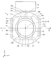
도 2는 제1 실시 형태에 의한 저압 EGR 장치의 단면을 도시하며, 도 3의 II-II선을 따라 취한 단면도이다.
도 3은 도 2의 III-III선을 따라 취한 제1 실시 형태에 의한 저압 EGR 장치의 정면도이다.
도 4는 도 2의 IV-IV선을 따라 취한 제1 실시 형태에 의한 저압 EGR 장치의 측면도이다.
도 5a 내지 도 5c는 제1 실시 형태에 의한 저압 EGR 장치의 하나의 작동 상태를 도시하며, 도 2 내지 도 4에 각각 대응하는 개략도이다.
도 6a 내지 도 6c는 제1 실시 형태에 의한 저압 EGR 장치의 또 다른 작동 상태를 도시하며, 도 2 내지 도 4에 각각 대응하는 개략도이다.
도 7a 내지 도 7c는 제1 실시 형태에 의한 저압 EGR 장치의 또 다른 작동 상태를 도시하며, 도 2 내지 도 4에 각각 대응하는 개략도이다.
도 8a 내지 도 8c는 제1 실시 형태에 의한 저압 EGR 장치의 또 다른 작동 상태를 도시하며, 도 2 내지 도 4에 각각 대응하는 개략도이다.
도 9a 내지 도 9c는 제1 실시 형태에 의한 저압 EGR 장치의 또 다른 작동 상태를 도시하며, 도 2 내지 도 4에 각각 대응하는 개략도이다.
도 10은 제1 실시 형태에 의한 저압 EGR 장치의 특성을 나타내는 그래프이다.
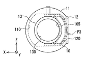
도 11은 본 발명의 제2 실시 형태에 의한 저압 EGR 장치의 단면을 도시하며, 도 12의 XI-XI선을 따라 취한 단면도이다.
도 12는 도 11의 XII-XII선을 따라 취한 제2 실시 형태에 의한 저압 EGR 장치를 도시하는 정면도이다.
도 13은 도 11의 XIII-XIII선을 따라 취한 제2 실시 형태에 의한 저압 EGR 장치를 도시하는 측면도이다.
도 14a 내지 도 14c는 제2 실시 형태에 의한 저압 EGR 장치의 하나의 작동 상태를 도시하며, 도 11 내지 도 13에 각각 대응하는 개략도이다.
도 15a 내지 도 15c는 제2 실시 형태에 의한 저압 EGR 장치의 또 다른 작동 상태를 도시하며, 도 11 내지 도 13에 각각 대응하는 개략도이다.
도 16a 내지 도 16c는 제2 실시 형태에 의한 저압 EGR 장치의 또 다른 작동 상태를 도시하며, 도 11 내지 도 13에 각각 대응하는 개략도이다.
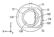
도 17은 본 발명의 제3 실시 형태에 의한 저압 EGR 장치의 단면을 도시하며, 도 18의 XVII-XVII선을 따라 취한 단면도이다.
도 18은 도 17의 XVIII-XVIII선을 따라 취한 제3 실시 형태에 의한 저압 EGR 장치의 정면도이다.
도 19는 도 17의 XIX-XIX선을 따라 취한 제3 실시 형태에 의한 저압 EGR 장치의 측면도이다.
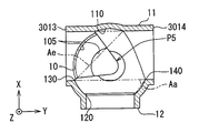
도 20a 내지 도 20c는 제3 실시 형태에 의한 저압 EGR 장치의 하나의 작동 상태를 도시하며, 도 17 내지 도 19에 각각 대응하는 개략도이다.
도 21a 내지 도 21c는 제3 실시 형태에 의한 저압 EGR 장치의 또 다른 작동 상태를 도시하며, 도 17 내지 도 19에 각각 대응하는 개략도이다.
도 22a 내지 도 22c는 제3 실시 형태에 의한 저압 EGR 장치의 또 다른 작동 상태를 도시하며, 도 17 내지 도 19에 각각 대응하는 개략도이다.
도 23은 본 발명의 제4 실시 형태에 의한 저압 EGR 장치의 단면을 도시하며, 도 24의 XXIII-XXIII선을 따라 취한 단면도이다.
도 24는 도 23의 XXIV-XXIV선을 따라 취한 제4 실시 형태에 의한 저압 EGR 장치의 정면도이다.
도 25는 도 23의 XXV-XXV선을 따라 취한 제4 실시 형태에 의한 저압 EGR 장치의 측면도이다.
도 26a 내지 도 26c는 제4 실시 형태에 의한 저압 EGR 장치의 하나의 작동 상태를 도시하며, 도 23 내지 도 25에 각각 대응하는 개략도이다.
도 27a 내지 도 27c는 제4 실시 형태에 의한 저압 EGR 장치의 또 다른 작동 상태를 도시하며, 도 23 내지 도 25에 각각 대응하는 개략도이다.
도 28a 내지 도 28c는 제4 실시 형태에 의한 저압 EGR 장치의 또 다른 작동 상태를 도시하며, 도 23 내지 도 25에 각각 대응하는 개략도이다.
도 29는 본 발명의 제5 실시 형태에 의한 저압 EGR 장치를 도시하며, 도 30의 XXIX-XXIX선을 따라 취한 단면도이다.
도 30은 도 29의 XXX-XXX선을 따라 취한 제5 실시 형태에 의한 저압 EGR 장치의 정면도이다.
도 31은 도 29의 XXXI-XXXI선을 따라 취한 제5 실시 형태에 의한 저압 EGR 장치의 측면도이다.
도 32a 내지 도 32c는 제5 실시 형태에 의한 저압 EGR 장치의 하나의 작동 상태를 도시하며, 도 29 내지 도 31에 각각 대응하는 개략도이다.
도 33a 내지 도 33c는 제5 실시 형태에 의한 저압 EGR 장치의 또 다른 작동 상태를 도시하며, 도 29 내지 도 31에 각각 대응하는 개략도이다.
도 34a 내지 도 34c는 제5 실시 형태에 의한 저압 EGR 장치의 또 다른 작동 상태를 도시하며, 도 29 내지 도 31에 각각 대응하는 개략도이다.
도 35는 도 17의 변형예를 도시하는 단면도이다.
도 36은 도 11 및 도 17의 변형예를 도시하는 단면도다.
도 37은 도 23 및 도 29의 변형예를 도시하는 단면도다. The following drawings are for illustrative purposes only and are not intended to limit the scope of the invention.
1 is a schematic view showing a structure of a system in which a low-pressure EGR apparatus according to a first embodiment of the present invention is applied to an internal combustion engine for a vehicle equipped with a turbocharger.
2 is a cross-sectional view of the low-pressure EGR apparatus according to the first embodiment taken along line II-II in Fig.
3 is a front view of the low-pressure EGR apparatus according to the first embodiment taken along the line III-III in FIG.
4 is a side view of the low-pressure EGR apparatus according to the first embodiment taken along the line IV-IV in Fig.
5A to 5C are schematic diagrams showing one operating state of the low-pressure EGR apparatus according to the first embodiment and corresponding to FIGS. 2 to 4, respectively.
Figs. 6A to 6C show another operating state of the low-pressure EGR apparatus according to the first embodiment, and are schematic views respectively corresponding to Figs. 2 to 4. Fig.
Figs. 7A to 7C show another operating state of the low-pressure EGR apparatus according to the first embodiment, and are schematic views respectively corresponding to Figs. 2 to 4. Fig.
Figs. 8A to 8C are schematic views corresponding to Figs. 2 to 4 respectively showing still another operating state of the low-pressure EGR apparatus according to the first embodiment. Fig.
Figs. 9A to 9C show another operating state of the low-pressure EGR apparatus according to the first embodiment, and are schematic views corresponding to Figs. 2 to 4, respectively.
10 is a graph showing the characteristics of the low-pressure EGR apparatus according to the first embodiment.
Fig. 11 is a cross-sectional view taken along the line XI-XI in Fig. 12, showing a cross-section of the low-pressure EGR apparatus according to the second embodiment of the present invention.
12 is a front view showing the low-pressure EGR apparatus according to the second embodiment taken along the line XII-XII in FIG.
13 is a side view showing the low-pressure EGR apparatus according to the second embodiment taken along line XIII-XIII in Fig.
Figs. 14A to 14C are schematic views corresponding to Figs. 11 to 13 showing one operating state of the low-pressure EGR apparatus according to the second embodiment. Fig.
Figs. 15A to 15C are schematic views corresponding to Figs. 11 to 13 showing another operating state of the low-pressure EGR apparatus according to the second embodiment. Fig.
Figs. 16A to 16C are schematic views corresponding to Figs. 11 to 13 showing another operating state of the low-pressure EGR apparatus according to the second embodiment. Fig.
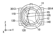
17 is a cross-sectional view taken along the line XVII-XVII in Fig. 18, showing a cross section of the low-pressure EGR apparatus according to the third embodiment of the present invention.
18 is a front view of the low-pressure EGR apparatus according to the third embodiment taken along the line XVIII-XVIII in Fig.
19 is a side view of the low-pressure EGR apparatus according to the third embodiment taken along the line XIX-XIX in Fig.
20A to 20C are schematic views corresponding to Figs. 17 to 19, respectively, showing one operating state of the low-pressure EGR apparatus according to the third embodiment.
Figs. 21A to 21C are schematic views corresponding to Figs. 17 to 19, respectively, showing still another operating state of the low-pressure EGR apparatus according to the third embodiment.
22A to 22C are schematic views corresponding to FIGS. 17 to 19, respectively, showing still another operating state of the low-pressure EGR apparatus according to the third embodiment.
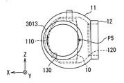
FIG. 23 is a cross-sectional view taken along line XXIII-XXIII of FIG. 24, showing a cross-section of the low-pressure EGR apparatus according to the fourth embodiment of the present invention.
24 is a front view of the low-pressure EGR apparatus according to the fourth embodiment taken along the line XXIV-XXIV in Fig.
25 is a side view of the low-pressure EGR apparatus according to the fourth embodiment taken along line XXV-XXV in Fig.
26A to 26C are schematic views corresponding to FIGS. 23 to 25, respectively, showing one operating state of the low-pressure EGR apparatus according to the fourth embodiment.
27A to 27C are schematic views corresponding to FIGS. 23 to 25, respectively, showing still another operating state of the low-pressure EGR apparatus according to the fourth embodiment.
28A to 28C are schematic views corresponding to FIGS. 23 to 25, respectively, showing still another operating state of the low-pressure EGR apparatus according to the fourth embodiment.
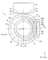
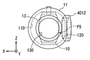
29 is a cross-sectional view taken along the line XXIX-XXIX of Fig. 30 showing the low-pressure EGR apparatus according to the fifth embodiment of the present invention.
Fig. 30 is a front view of the low-pressure EGR apparatus according to the fifth embodiment taken along the line XXX-XXX in Fig.
31 is a side view of the low-pressure EGR apparatus according to the fifth embodiment taken along the line XXXI-XXXI in FIG.
32A to 32C are schematic views corresponding to FIGS. 29 to 31, respectively, showing one operating state of the low-pressure EGR apparatus according to the fifth embodiment.
33A to 33C show still another operating state of the low-pressure EGR apparatus according to the fifth embodiment, and are schematic views respectively corresponding to Figs. 29 to 31. Fig.
FIGS. 34A to 34C are schematic views corresponding to FIGS. 29 to 31, respectively, showing still another operating state of the low-pressure EGR apparatus according to the fifth embodiment.
35 is a sectional view showing a modification of Fig.
Fig. 36 is a sectional view showing a modification of Figs. 11 and 17. Fig.
37 is a sectional view showing a modification of Figs. 23 and 29. Fig.
본 발명의 다양한 실시 형태가 첨부 도면을 참조하여 설명될 것이다. 이하 각각의 실시 형태에서, 유사한 구성 요소들은 동일한 참조 부호로 지시될 것이며, 명료성을 위해 중복 설명되지 않을 수 있다. 이하 각각의 실시 형태에서, 구조의 일부분만이 설명될 경우, 구조의 나머지 부분은 선행해서 설명한 실시 형태(들)의 구조와 동일하다. 또한, 각 실시 형태에서 명시적으로 설명된 구성 요소들의 조합뿐만 아니라, 조합이 불이익을 초래하지 않는 한, 이하 설명에서 명시적으로 설명되지 않더라도 하나 이상의 이하 실시 형태의 구성 요소는 또 다른 하나 이상의 실시 형태의 구성 요소와 부분적으로 조합 수 있다. Various embodiments of the present invention will be described with reference to the accompanying drawings. In the following embodiments, similar components will be denoted by the same reference numerals, and may not be redundantly described for the sake of clarity. Hereinafter, in each embodiment, when only a part of the structure is described, the remaining part of the structure is the same as the structure of the embodiment (s) explained earlier. Furthermore, unless explicitly described in the following description, components of one or more of the following embodiments may be used in combination with one or more other implementations, as well as combinations of components explicitly described in the embodiments, Can be partially combined with the elements of the form.
(제1 실시 형태) (First Embodiment)
도 1에 도시한 바와 같이, 저압 EGR 장치(저압 루프 EGR 장치로도 또한 지칭됨)(1)가 터보 과급기(2)를 탑재한 차량(예를 들어, 자동차)용 내연 기관(3)에 제공된다. 1, a low-pressure EGR device (also referred to as a low-pressure loop EGR device) 1 is provided in an
본 실시 형태에서, 내연 기관(3)은 디젤 엔진이며, 실린더(30) 내에서 디젤 연료(본 발명의 연료 역할을 함)를 연소시킨다. 내연 기관(3)은 흡입 에어(본 명세서에서 흡입 가스로도 또한 지칭됨)를 실린더(30)로 공급하는 흡기 통로(31)를 가진다. 또한, 내연 기관(3)은 각 실린더(30) 내에서의 연소에 의해 발생한 배기 가스를 외부로 배출하기 위해 배기 통로(32)를 가진다. 또한, 내연 기관(3)은 배기 통로(32)로 배출된 배기 가스(EGR 가스의 역할을 함)의 일부를 흡기 통로(31)로 재순환시키기 위해 EGR 통로(33)를 가진다.In the present embodiment, the
흡기 통로(31)에는 에어 클리너(34), 인터쿨러(35), 및 스로틀 밸브(36)가 설치된다. 에어 클리너(34)는 외부로부터 도입되는 에어 내에 포함된 먼지와 같은 고체 입자상 물질(이물질)을 포집한다. 인터쿨러(35)는 터보 과급기(2)의 컴프레서(21)에 의해 압축되어 고온을 갖는 흡입 에어를 팽창시킴으로써 흡입 에어를 냉각시킨다. 스로틀 밸브(36)는 각 대응 실린더(30)로 공급된 흡입 에어의 양을 조절하기 위해 밸브 개방도를 조정하도록 구동된다. An
배기 통로(32)에는 배기 처리 장치(37)가 설치된다. 배기 처리 장치(37)는 배기 통로(32)로 배출된 배기 가스를 정화한다. 여기서, 배기 가스에 포함된 입자상 물질을 포집하기 위한 배기 처리 장치(37)로서 디젤 입자상 물질 필터(DPF)가 채용될 수 있다는 것이 주지되어야 한다. 대안적으로 또는 추가적으로, SCR(Selective Catalytic Reduction) 장치, LNT(Lean NOx Trap) 장치, 및/또는 NSR(NOx Storage Reduction) 장치가 배기 가스에 포함된 Nox를 환원하는 배기 처리 장치(37)로서 이용될 수 있다.An
EGR 통로(33)는 배기 통로(32)와 흡기 통로(31) 사이에서 연통한다. 구체적으로, EGR 통로(33)은 터보 과급기(2)의 터빈(20) 및 배기 처리 장치(37)의 하류측의 위치에서 배기 통로(32)에 형성되는 유동 분기부(320)와 연통한다. 또한, EGR 통로(33)는 에어 클리너(34)의 하류측과 컴프레서(21)의 상류측의 위치에서 흡기 통로(31)에 형성되는 유동 합류부(310)와 연통한다. 상술한 구조에 의해, EGR 통로(33)는 배출 가스의 일부인 EGR 가스를, 낮은 배기압을 갖는 유동 분기부(320)로부터 낮은 흡기 부압을 갖는 유동 합류부(310)로 재순환시켜서, EGR 가스를 흡입 에어와 혼합시킨다. The
EGR 통로(33)에는 EGR 쿨러(38)가 설치된다. EGR 쿨러(38)는 흡기 통로(31)로 EGR 가스를 재순환시킬 때 실린더(30)로 흡입되는 EGR 가스를 냉각함으로써, NOx의 발생을 억제한다. An
터보 과급기(2)는 적어도 한 세트의 터빈(20) 및 컴프레서(21)를 가진다. 터빈(20)은 배기 처리 장치(37) 및 유동 분기부(320)의 상류측의 위치에서 배기 통로(32)에 설치된다. 컴프레서(21)는 유동 합류부(310)의 하류측과 스로틀 밸브(36) 및 인터쿨러(35)의 상류측의 위치에서 흡기 통로(31)에 설치된다. 상술한 구조에 의해, 터빈(20)은 배기 통로(32)로 배출된 배기 가스의 내부 에너지에 의해 회전함으로써, 터빈(20)과 동축 상에 연결된 컴프레서(21)를 구동한다. 그 결과, 흡입 에어는 압축되어 각 실린더(30)로 과급된다. 여기서, 본 발명의터보 과급기(2)로서는 도 1에 도시된 단일 터보 과급기일 수 있고, 또는 트윈 스크롤 터보 과급기, 가변 용량식 터보 과급기, 패러럴 트윈 터보 과급기, 시퀀셜 터보 과급기, 또는 전동 어시스티식 터보 과급기와 같은 또 다른 타입의 터보 과급기일 수 있음이 주지되어야 한다.The turbocharger (2) has at least one set of turbine (20) and a compressor (21). The
저압 EGR 장치(1)는 흡기 통로(31)의 유동 합류부(310) 및 통로부(311, 312)와 EGR 통로(33)의 통로부(330)에 형성된다. 통로부(311, 312)는 흡기 통로(31)의 유동 합류부(310)의 양측(상류측 및 하류측)에 각각 위치한다. 통로부(330)는 EGR 통로(33)의 유동 합류부(310)를 향해 연장한다. 도 2 내지 도 4에 도시된 바와 같이, 저압 EGR 장치(1)는 밸브체(10), 밸브 하우징(11), EGR 덕트(12), 에어 덕트(13), 혼합 덕트(14) 및 전동 액츄에이터(15)를 포함한다. 설명의 이해를 돕기 위해, 도 2 내지 도 4 및 도 5 내지 도 9에서, X 방향, Y 방향 및 Z 방향이 직교 좌표계(3차원 좌표계)에서 규정된다.The low
밸브체(10)는 금속으로 제조된 볼 밸브이다. 밸브체(10)는 시트부(100), 복수의 아암부(101) 및 밸브 샤프트부(102)를 포함한다. 시트부(100)는 부분적 구각 형상을 가진다. 이에 의해, 시트부(100)의 외면은 부분적 구면으로 형상인 볼록한 시일면(103)을 형성한다. 시트부(100)는 볼록한 시일면(103)의 곡률 중심(Cv){예를 들어, 볼록한 시일면(103)이 형성되는 외면을 갖는 가상의 구체의 중심}을 통하는 Z 방향으로 연장되는 회전축(Lv)을 중심으로 회전가능하다. The
아암부(101)는 시트부(100)과 일체 회전가능하고, 아암부(101)의 개수는 이 경우에서는 2개이다. 아암부(101)는 회전축(Lv)에 실질적으로 직각이며 그에 따라 서로 실질적으로 평행이다. 아암부(101)는 각각 부채 형상을 갖는 평판 형태의 형상을 가진다. 아암부(101)는 회전축(Lv)을 따라 연장되는 Z 방향으로 서로 대향하는 시트부(100)의 두 에지로부터 회전축(Lv)을 향해 각각 회전축(Lv)의 반경 방향{예를 들어, 회전축(Lv)에 직각인 방향}으로 연장된다. 아암부(101)는 에어 덕트(13)의 내경보다 큰 거리로 회전축(Lv)의 방향에서 서로 이격된다{더 구체적으로, 에어 덕트(13)의 유입구(130)의 내경이 이하에 설명된다}. 아암부(101)들 간의 이 거리는 에어 덕트(13)의 내경{더 구체적으로, 에어 덕트(13)의 유입구(130)의 내경}과 동일하도록 대안적으로 설정될 수 있다. 일부 경우에, 아암부(101)들 간의 거리는 필요에 따라 에어 덕트(13)의 내경{더 구체적으로, 에어 덕트(13)의 유입구(130)의 내경}보다 작게 설정될 수 있다. 상술한 구조에 의해, 공간부(105)가 아암부(101)들 사이의 위치로부터 시트부(100)의 내주연부측으로 연장되도록 밸브체(10)에 형성된다.The
밸브 샤프트부(102)는 시트부(100) 및 아암부(101)와 일체 회전가능하도록 형성된다. 본 실시 형태에서, 밸브 샤프트부(102)를 형성하는 금속 부재는 시트부(100) 및 아암부(101)를 형성하는 금속 부재에 일체 회전가능하게 고정된다. 밸브 샤프트부(102)는 회전축(Lv)을 따라 선형적으로 연장되는 원통형 형상을 가진다. 밸브 샤프트부(102)는 아암부(101) 중 하나로부터 다른 하나의 아암부(101)의 반대측을 향하여 연장된다. The
밸브 하우징(11)은 금속으로 제조되고, 구각 형상을 가진다. 밸브 하우징(11)은 구형 공간으로 형성되는 밸브 챔버(110)를 가진다. 밸브 챔버(110)는 흡기 통로(31)의 유동 합류부(310)를 형성한다. 밸브 챔버(110)는 밸브체(10)의 시트부(100) 및 아암부(101)를 회전가능하게 수용한다. 밸브 하우징(11)의 내면은, Z 방향에 있어서 서로 대향하는 밸브체(10)의 양측에 2개의 평면형 지지 표면(111)을 형성한다. 밸브 챔버(110)에 노출되는 평면형 지지 표면(111)은 회전축(Lv)에 실질적으로 직교함으로써, 서로 평행한다. 평면형 지지 표면(111)은 밸브체(10)의 회전 시에 아암부(101)를 각각 미끄럼 접촉 지지한다. The
밸브체(10)를 Z 방향에서 보유 지지하는 평면형 지지 표면(111)들 사이에 위치하는 밸브 하우징(11)의 내면의 일부는, 부분적 구면 형상을 갖는 오목한 시일면(113)을 형성한다. 오목한 시일면(113)은 EGR 덕트(12)와 에어 덕트(13) 사이에서 연장되고, EGR 덕트(12)와 혼합 덕트(14) 사이에서 연장되고, 에어 덕트(13)과 혼합 덕트(14) 사이에서 연장된다. 오목한 시일면(113)는 밸브 챔버(110)에 노출되고, 오목한 시일면(113)의 곡률 중심(Ch){예를 들어, 오목한 시일면(113)이 형성되는 외면을 갖는 가상의 구체 중심}은 볼록한 시일면(103)의 곡률 중심(Cv)에 실질적으로 일치한다. 이에 의해, 오목한 시일면(113)은 밸브체(10)의 회전 시에 볼록한 시일면(103)과 미끄럼 접촉한다. A part of the inner surface of the
평면형 지지 표면(111) 중 하나를 형성하는 밸브 하우징(11)의 벽부는 베어링부(112)를 형성한다. 밸브 샤프트부(102)는 기밀식이며 베어링부(112)를 통해 회전가능하게 연장된다. 이에 의해, 베어링부(112)는 밸브 챔버(110) 내에 위치하는 아암부(101)로부터 밸브 하우징(11)의 외부로 연장되는 밸브 샤프트부(102)을 회전가능하게 지지한다. The wall portion of the
EGR 덕트(12)는 금속으로 제조되며, 원통 관형 형상을 가진다. 유동 합류부(310)을 향해 연장되는 통로부(330)가 EGR 덕트(12)의 내부에 형성된다. EGR 덕트(12)는 회전축(Lv)에 실질적으로 직교하는 X 방향에 있어서, 밸브 하우징(11)으로부터 회전축(Lv)의 반대측을 향해 연장된다. EGR 덕트(12)은 중심축(Le)은 곡률 중심(Cv, Ch)을 통해 연장되고, 회전축(Lv)에 실질적으로 직교한다. 중심축(Le)으로부터 측정한 EGR 덕트(12)의 내주연면의 반경은, 오목한 시일면(113)의 곡률 중심(Ch)으로부터 측정한 오목한 시일면(113)의 곡률 반경보다 작게 설정된다.The
EGR 덕트(12)는 통로부(330)의 최하류단을 형성하는 유입구(120)를 가진다. 유입구(120)의 내주연면은 유입구(120)의 내주연면의 전체 둘레 범위에 걸쳐 오목한 시일면(113)에 접속됨으로써, 통로부(330)를 유동 합류부(310)에 연통시킨다. 이에 의해, 유입구(120)는 도 6a 내지 도 9c에 도시된 밸브체(10)의 회전 위치(P2 내지 P5)에서 유동 분기부(320)(도 1 참조)로부터 공급되는 EGR 가스를 밸브 챔버(110)로 안내한다. 반면, 도 5a 내지 도 5c에 도시된 밸브체(10)의 회전 위치(P1)에서 유입구(120)는 완전 폐쇄됨으로써, 밸브 챔버(110)로의 EGR 가스의 유입이 차단된다. The
여기서, 도 2 및 도 4에 도시된 바와 같이, 고무제이며 링 형상인 시일 부재(113a)가 밸브 하우징(11)에서 EGR 덕트(12)의 내주연면과 오목한 시일면(113) 사이의 연결부에 고정된다. 이에 의해, 밸브체(10)가 EGR 덕트(12)의 유입구(120)를 완전 폐쇄하는 회전 위치(본 명세서에서 완전 폐쇄 회전 위치로도 또한 지칭됨)(P1)에서, 볼록한 시일면(103)과 오목한 시일면(113) 사이의 간극이 시일 부재(113a)에 의해 기밀식으로 밀봉된다.2 and 4, a
도 2 내지 도 4를 참조하면, 에어 덕트(13)는 금속으로 제조되며, 원통 관형 형상을 가진다. 유동 합류부(310)의 상류측에 위치하는 통로부(311)는 에어 덕트(13)의 내부에 형성된다. 에어 덕트(13)는 회전축(Lv) 및 중심축(Le)과 실질적으로 직교하는 Y 방향에서, 밸브 하우징(11)으로부터 회전축(Lv) 및 중심축(Le)의 반대측을 향하여 연장된다. 에어 덕트(13)의 중심축(La)은 곡률 중심(Cv, Ch)을 통해 연장되고, 회전축(Lv)에 실질적으로 직교한다. 따라서, 밸브체(10)의 회전축(Lv)은 EGR 덕트(12)의 중심축(Le) 및 에어 덕트(13)의 중심축(La) 양자와 교차한다. 도 2에 도시된 바와 같이, 에어 덕트(13)의 중심축(La)과 EGR 덕트(12)의 중심축(Le) 사이에는 직각(θar)이 형성된다. 중심축(La)로부터 측정한 에어 덕트(13)의 내주연면의 반경은 오목한 시일면(113)의 곡률 반경보다 작게 설정된다. 2 to 4, the
도 2 내지 도 4에 도시된 바와 같이, 에어 덕트(13)는 통로부(311)의 최하류단을 형성하는 유입구(130)를 가진다. 유입구(130)의 내주연면은 유입구(130)의 내주연면의 전체 둘레 범위위에 걸쳐 오목한 시일면(113)에 접속됨으로써, 유입구(130)는 통로부(311)를 유동 합류부(310)에 연통시킨다. 이에 의해, 도 5a 내지 도 8c에 도시된 밸브체(10)의 각 회전 위치(P1 내지 P4)에서 유입구(130)가 개방될 때, 유입구(130)는 흡입 에어를 밸브 챔버(110)로 안내한다. 반면, 도 9a 내지 도 9c에 도시된 회전 위치(P5)에서, 유입구(130)는 밸브체(10)에 의해 최대로 제한되어{예를 들어, 유입구(130)의 개방도가 최소화되어}, 유입구(130)를 통한 밸브 챔버(110)로의 흡입 에어의 유량이 최대로 제한된다{예를 들어, 밸브 챔버(110)로의 흡입 에어의 유량이 최소화된다}.As shown in Figs. 2 to 4, the
도 2 및 도 3을 참조하면, 혼합 덕트(14)는 금속으로 제조되며, 원통 관형 형상을 가진다. 유동 합류부(310)의 하류측에 위치하는 통로부(312)는 혼합 덕트(14)의 내부에 형성된다. 혼합 덕트(14)는 Y 방향에서 밸브 하우징(11)으로부터 에어 덕트(13), 회전축(Lv) 및 중심축(Le)의 반대측을 향해 연장된다. 혼합 덕트(14)의 중심축(Lm)은 곡률 중심(Cv, Ch)을 통해 연장되고, 회전축(Lv)과 실질적으로 직교한다. 도 2에 도시된 바와 같이, 혼합 덕트(14)의 중심축(Lm)과 EGR 덕트(12)의 중심축(Le) 사이에는 직각(θmr)이 형성된다. 이에 의해, 혼합 덕트(14)의 중심축(Lm)과 에어 덕트(13)의 중심축(La)은 회전축(Lv) 및 곡률 중심(Ch)에 대해 오프셋되지 않고, 서로 중첩된다. 즉, 혼합 덕트(14)의 중심축(Lm) 및 에어 덕트(13)의 중심축(La)은 서로 동축상에 있다. 중심축(Lm)으로부터 측정한 혼합 덕트(14)의 내주연면의 반경은 오목한 시일면(113)의 곡률 반경보다 작게, 본 실시 형태에서는 에어 덕트(13)의 내주연면의 반경과 실질적으로 동일하게 설정된다. 2 and 3, the mixing
혼합 덕트(14)는 통로부(312)의 최상류단을 형성하는 유출구(140)를 가진다. 유출구(140)의 내주연면은 유출구(140)의 내주연면의 전체 둘레 범위에 걸쳐 오목한 시일면(113)에 접속됨으로써, 유출구(140)는 통로부(312)를 유동 합류부(310)에 연통시킨다. 이에 의해, EGR 가스 및 흡입 에어 중 적어도 하나는 밸브체(10)의 회전 위치에 따라 유출구(140)를 통해 밸브 챔버(110)로부터 배출된다. 구체적으로는, 도 5a 내지 도 5c에 도시된 밸브체(10)의 완전 폐쇄 회전 위치(P1)에서, 밸브 챔버(110)에 개방된 유입구(130)를 갖는 에어 덕트(13)로부터 유입된 흡입 가스는, 밸브 챔버(110)로부터, 유출구(140)를 가지며 항상 개방된 혼합 덕트(14)로 유출된다. 반면, 도 6a 내지 도 9c에 도시된 밸브체(10)의 회전 위치(P2 내지 P5)에서, 밸브 챔버(110)로 개방된 유입구(120)를 갖는 EGR 덕트(12)로부터 공급되는 EGR 가스 및 밸브 챔버(110)로 개방된 유입구(130)를 갖는 에어 덕트(13)로부터 공급된 흡입 가스는 밸브 챔버(110) 내에서 혼합되고, EGR 가스 및 흡입 가스의 이 혼합물은 밸브 챔버(110)로부터 유출구(140)를 가지며 항상 개방된 혼합 덕트(14)로 유출된다.The mixing duct (14) has an outlet (140) forming the most upstream end of the passageway (312). The inner circumferential surface of the
본 실시 형태에서, 도 5a 내지 도 9c에 도시된 바와 같이, 밸브 하우징(11)의 밸브 챔버(110) 내에 가상 에어 영역(Aa)이 형성된다. 구체적으로, 도 5a, 6a, 7a, 8a, 및 9a에 도시된 바와 같이, 원통 관형 형태(원통형 형태)이며, 에어 덕트(13)의 유입구(130)의 내주연 에지와 혼합 덕트(14)의 유출구(140)의 내주연 에지 사이를 최단 거리로 연결하는 가상 영역으로서 가상 에어 영역(Aa)이 형성된다. 이 경우에, 공간부(105)의 존재 때문에, 도 5a 내지 도 5c에 도시된 밸브체(10)의 완전 폐쇄 회전 위치(P1)로부터 도 7a 내지 도7c에 도시된 EGR 덕트(12)의 유입구(120)를 부분적으로 개방하는 밸브체(10)의 소정의 중간 회전 위치(P3)까지, 밸브체(10)의 회전 각도 범위(Rcm)(도 10 참조) 전체에 걸쳐, 밸브체(10)는 가상 에어 영역(Aa)으로부터 완전히 변위된다. 그 결과로서 유입구(130)는 밸브체(10)의 회전 각도 범위(Rcm) 전체에 걸쳐 밸브체(10)에 의해 완전히 개방된 상태에서 보유 지지된다. 반면, 밸브체(10)는, 밸브체(10)에 의한 유입구(130)의 유동 제한이 최대화되는{예를 들어, 유입구(130)의 개방도가 최소화되는} 도 9a 내지 도 9c에 도시된 회전 위치(본 명세서에서 최대 제한 회전 위치로도 지칭됨)(P5)로부터, 도 8에 도시된 중간 회전 위치(P4)를 거치고, 중간 회전 위치(P3)의 중간 회전 위치(P4)측 앞에 위치하는 회전 위치{도 10의 회전 위치(P6) 참조}까지, 회전 각도 범위(Rsm)(도 10 참조)에서, 가상 에어 영역(Aa)과 중첩된다. 최대 제한 회전 위치(P5)에서는, 밸브체(10) 전체가 가상 에어 영역(Aa)과 중첩되지만, 도 9a에 도시된 바대로, 볼록한 시일면(103)과 오목한 시일면(113) 사이에는 간극이 형성된다. 이 결과로서, 유입구(130)는 회전 각도 범위(Rsm) 전체에 걸쳐 밸브체(10)에 의해 부분 개방되거나 부분 폐쇄되는 상태로 위치된다.In this embodiment, a virtual air region Aa is formed in the
또한, 본 발명의 실시 형태에서, 도 9a에 도시된 바와 같이, 가상 EGR 영역(Ae)이 밸브 하우징(11)의 밸브 챔버(110)에 형성된다. 구체적으로, 도 5a, 도 6a, 도 7a, 도 8a, 및 도 9a에 도시된 바대로, 원통 관형 형태(원통형 형태)이며, EGR 덕트(12)의 유입구(120)의 내주연 에지와 혼합 덕트(14)의 유출구(140)의 내주연 에지 사이를 최단 거리로 연결하는 가상 영역으로서 가상 EGR 영역(Ae)이 형성된다. 이 경우에, 공간부(105)의 존재 때문에, 도 9a 내지 도 9c에 도시된 최대 제한 회전 위치(P5)로부터 최대 제한 회전 위치(P5) 앞에 위치하는 회전 위치{도 10의 회전 위치(P7) 참조}까지, 밸브체(10)의 회전 각도 범위(Rss) 전체에 걸쳐, 밸브체(10)는 가상 EGR 영역(Ae)으로부터 완전히 변위된다. 그 결과로서, 유입구(120)는 최대 제한 회전 위치(P5)를 포함하는 회전 각도 범위(Rss) 전체에 걸쳐 밸브체(10)에 의해 완전 개방된 상태에서 보유 지지된다. 반면, 도 5a 내지 도 8c에 도시된 바와 같이, 밸브체(10)는 회전 각도 범위(Rss) 이외의 다른 회전 각도 범위에서 가상 EGR 영역(Ae)과 중첩된다. 그 결과로서, 유입구(120)는 밸브체(10)에 의해 부분 개방 또한 부분 폐쇄된 상태, 또는 밸브체(10)에 의해 완전 폐쇄된 상태에서 보유 지지된다.Further, in the embodiment of the present invention, as shown in Fig. 9A, the virtual EGR region Ae is formed in the
또한, 본 실시 형태에서, 밸브 하우징(11) 및 덕트(12 내지 14) 각각의 절반을 형성하는 금속 부재가, 밸브 하우징(11) 및 덕트(12 내지 14) 각각의 나머지 절반을 형성하는 금속 부재에, 밸브체(10)를 Z 방향에서 그 사이에 개재한 상태로 고정된다. 도 3, 도 4, 도 5b, 도 5c, 도 6b, 도 6c, 도 7b, 도 7c, 도 8b, 도 8c, 도 9b 및 도 9C에서, 이들 금속 부재가 서로 고정되는 이들 금속 부재 사이의 경계면은 명료성을 위해 생략된다. In the present embodiment, the metal member forming half of each of the
도 3 및 도 4에 도시된 바와 같이, 전동 액츄에이터(15)는 예를 들어 전동 모터에 감속 기구를 조합하여 형성된다. 전동 액츄에이터(15)는 밸브 하우징(11)의 외부에 있어서 밸브 샤프트부(102)와 동축 상에 연결되는 출력 샤프트부(미도시)를 가진다. 전동 액츄에이터(15)는 내연 기관(3)을 제어하는 엔진 ECU로부터 내연 기관(3)의 작동 상태에 따른 제어 명령을 받는다. 전동 액츄에이터(15)는 제어 명령에 따라 출력 샤프트부로부터 회전 토크를 출력함으로써, 밸브 샤프트부(102)를 회전시킨다. As shown in Figs. 3 and 4, the
이하, 저압 EGR 장치(1)의 전체 작동을 설명한다. 도 10에서, 흡입 에어의 최대 유량(Famax)을 100%로 설정했을 때의 흡입 에어의 유량과, EGR 가스의 최대 유량(Femax)을 100%으로 설정했을 때의 EGR 가스의 유량 양자를 공통의 종축에서 도시한다.The overall operation of the low-
예를 들어 내연 기관(3)이 고부하 운전되는 경우에, 엔진 ECU로부터 출력된 제어 명령에 따라, 전동 액츄에이터(15)는 도 5a 내지 도 5c 및 도 10에 도시된 완전 폐쇄 회전 위치(P1)까지 밸브체(10)를 회전시킨다. 이에 의해, EGR 덕트(12)가 완전 폐쇄되고, 에어 덕트(13)가 완전 개방된다. 이 때, 에어 덕트(13)로 부터 밸브 챔버(110)를 통해 혼합 덕트(14)로 유출되는 흡입 에어의 유량은 도 10에 도시된 최대 유량(Famax)이 된다. 반면, EGR 가스는 EGR 덕트(12)로부터 밸브 챔버(110)를 통해 혼합 덕트(14)로 유출되지 않으므로, EGR 가스의 유량은 도 10에 도시된 바와 같이 영(0)이 된다. 이 결과, 흡입 에어에 대한 EGR 가스의 혼합 비율인 EGR율은 영(0값)으로 조정된다. For example, in the case where the
예를 들어 내연 기관(3)이 EGR율을 저율이게 확보해서 운전되는 경우에, 엔진 ECU로부터 출력된 제어 명령에 따라, 전동 액츄에이터(15)는 도 6a 내지 도 6c 및 도 10에 도시된 중간 회전 위치(P2)까지 밸브 챔버(110)를 회전시킨다. 이에 의해, 에어 덕트(13)는 완전 개방 상태로 유지되고, EGR 덕트(12)는 개방되기 시작한다. 이 때, 에어 덕트(13)로부터 밸브 챔버(110)를 통해 혼합 덕트(14)로 유출되는 흡입 에어의 유량은 도 10에 도시된 최대 유량(Famax)이 된다. 반면, EGR 덕트(12)로부터 밸브 챔버(110)를 통해 혼합 덕트(14)로 유출되는 EGR 가스의 유량은 도 10에 도시된 최소 유량(Femin)으로 제한된다. 그 결과, EGR율은 영(0값)에 가까운 저율로 제한된다. For example, in the case where the
예를 들어 내연 기관(3)이 EGR율을 상술한 저율보다 높게 해서 운전되는 경우에, 엔진 ECU로부터 출력된 제어 명령에 따라, 전동 액츄에이터(15)는 도 7a 내지 도 7c 및 도 10에 도시된 중간 회전 위치(P3)까지 밸브체(10)를 회전시킨다. 이에 의해, 에어 덕트(13)는 완전 개방 상태로 유지되고, EGR 덕트(12)는 중간 회전 위치(P2)에서 밸브체(10)를 보유 지지될 때 설정되는 EGR 덕트(12)의 개방도보다 큰 개방도로 부분 개방된다. 이 때, 에어 덕트(13)로부터 밸브 챔버(110)를 통해 혼합 덕트(14)로 유출되는 흡입 에어의 유량은 도 10에 도시된 최대 유량(Famax)이 된다. 반면, EGR 덕트(12)로부터 밸브 챔버(110)를 통해 혼합 덕트(14)로 유출되는 EGR 가스의 유량은 도 10에 도시된 바와 같이, 상기 최소 유량(Femin) 보다 높은, 작은 유량(Fel)으로 제한된다. 그 결과, EGR율은 최대율보다 작은 범위로 조정된다.For example, in the case where the
예를 들어 배기압이 충족된 상태에서 내연 기관(3)이 높은 EGR율로 운전되는 경우에, 엔진 ECU로부터 출력된 제어 명령에 따라, 전동 액츄에이터(15)는 도 8a 내지 도 8c 및 도 10에 도시된 중간 회전 위치(P4)까지 밸브체(10)를 회전시킨다. 이에 의해, 에어 덕트(13)는 폐쇄되기 시작하고, EGR 덕트(12)는 밸브체(10)가 중간 회전 위치(P3)에 위치한 상태에서 EGR 덕트(12)의 개방도보다 큰 개방도로 부분 개방된다. 이 때, 에어 덕트(13)로부터 밸브 챔버(110)를 통해 혼합 덕트(14)로 유출되는 흡입 에어의 유량은 도 10에 도시된 최대 유량(Famax)보다 작은 유량(Fal)으로 제한된다. 반면, EGR 덕트(12)로부터 밸브 챔버(110)를 통해 혼합 덕트(14)로 유출되는 EGR 가스의 유량은 도 10에 도시된 바와 같이, 최소 유량(Femin)보다 실질적으로 큰 유량(Feu)이 된다. 그 결과, EGR율은 최대율보다 작은 범위로 증가된다.For example, in a case where the
예를 들어 배기압이 부족한 상태에서 내연 기관(3)이 높은 EGR율로 운전되는 경우에, 엔진 ECU로부터 출력된 제어 명령에 따라, 전동 액츄에이터(15)는 도 9a 내지 도 9c 및 도 10에 도시된 최대 제한 회전 위치(P5)까지 밸브체(10)를 회전시킨다. 이에 의해, 에어 덕트(13)의 제한이 최대화되고{예를 들어, 에어 덕트(13)의 개방도가 최소화되고}, EGR 덕트(12)는 완전 개방된다. 이 때, 에어 덕트(13)로부터 밸브 챔버(110)를 통해 혼합 덕트(14)로 유출되는 흡입 에어의 유량은 도 10에 도시된 최소 유량(Famin)으로 감소된다. 반면, EGR 덕트(12)로부터 밸브 챔버(110)를 통해 혼합 덕트(14)로 유출되는 EGR 가스의 유량은 도 10에 도시된 최대 유량(Femax)까지 증가된다. 그 결과, EGR율은 최대율로 조정된다.For example, in a case where the
제1 실시 형태의 작용 효과를, 이하에 설명한다. The operation and effect of the first embodiment will be described below.
제1 실시 형태에 의하면, 오목한 시일면(113)은 밸브체(10)를 수용하는 밸브 챔버(110)에 노출되고 부분적 구면 형상이다. 오목한 시일면(113)은 부분적 구면 형상의 볼록한 시일면(103)과 미끄럼 접촉하며, 밸브 하우징(11)의 EGR 덕트(12)와 에어 덕트(13) 사이에 형성된다. EGR 덕트(12) 및 에어 덕트(13) 양자의 개방도를 제어하기 위해 상용되는 밸브체(10)는, 볼록한 시일면(103)의 곡률 중심(Cv)을 통해 연장되는 회전축(Lv)을 중심으로 회전함으로써, EGR 덕트(12)의 개방도 및 에어 덕트(13)의 개방도를 다른 개방도로 동시에 각각 제어할 수 있다. 구체적으로, 밸브체(10)는 밸브체(10)가 EGR 덕트(12)를 완전 폐쇄하는 밸브체(10)의 완전 폐쇄 회전 위치(P1)로부터, 밸브체(10)가 EGR 덕트(12)를 부분 개방하는 밸브체(10)의 소정의 중간 회전 위치(P3)까지 밸브체(10)의 회전 각도 범위(Rcm)에서 에어 덕트(13)를 개방할 수 있다. 이 때, 특히, 밸브체(10)는 에어 덕트(13)의 유입구(130)와 혼합 덕트(14)의 유출구(140)의 사이를 연결하는 가상 에어 영역(Aa)으로부터 변위된다. 따라서, 흡기 통로(31)의 유동 합류부(310)의 상류측에 위치한 통로부(311)를 형성하는 에어 덕트(13)는 완전 개방 상태로 유지되어, 흡입 에어의 흐름을 저해하지 않는다. 그러므로, 흡입 에어의 압력 손실이 최소화된 상태에서, EGR 가스의 재순환 유량이 0 또는 필요 최소 유량으로 감소된다. 이에 반해, 밸브체(10)는 EGR 덕트(12)를 완전 개방하기 위한 완전 개방 회전 위치인 회전 위치(P5)로부터 앞서 설명한 중간 회전 위치(P3) 전에 위치하는 회전 위치까지의 각도 범위(Rsm)로 에어 덕트(13)를 제한할 수 있다{즉, 밸브체(10)가 에어 덕트(13)의 개방을 감소시킬 수 있다}. 이때, 흡기 통로(31) 내의 유동 합류부(310)를 형성하는 밸브 챔버(110)에 원활하게 EGR 가스를 공급하는 EGR 덕트(12)에 비교하여, 에어 덕트(13)는 밸브 챔버(110)에 공급하는 흡입 에어의 유량을 제한한다. 그러므로, 흡기 부압은 증가하고, 이에 따라, EGR 가스의 재순환 유량이 증가한다.According to the first embodiment, the
이와 같이 제1 실시 형태에 따르면, 저압 EGR 장치(1)로서 요구되는 요구 동작 특성을 만족하고, EGR 덕트(12)와 에어 덕트(13)에 밸브체(10)를 상용하여 저압 EGR 장치(1)의 구조의 간단화와, 저압 EGR 장치(1)의 크기를 감소시키는 것을 가능하게 한다.According to the first embodiment, the low-pressure EGR device 1 (1) satisfies the required operating characteristics required of the low-
또한, 제1 실시 형태에 따르면, 밸브체(10)가 에어 덕트(13)를 최대로 제한하는 최대 제한 회전 위치(P5)에 위치할 때, 밸브체(10)는 EGR 덕트(12)의 유입구(120)와 혼합 덕트(14)의 유출구(140)의 사이를 연결하는 가상 EGR 영역(Ae)으로부터 변위된다. 이에 따라, 밸브체(10)는 EGR 덕트(12)를 완전 개방한다. 따라서, EGR 덕트(12)를 완전 개방하여 EGR 가스의 재순환 유량을 증가시킬 때, EGR 가스의 흐름을 저해하지 않고, EGR 가스의 압력 손실을 감소시킬 수 있다. 또한, 가상 EGR 영역(Ae)에서 변위된 밸브체(10)에 대하여 수증기가 포함된 고온의 EGR 가스와 충돌할 확률이 적어진다. 그러므로, 최대 제한 회전 위치(P5)에 보유 지지된 밸브체(10)에 대하여 냉온의 흡입 에어가 충돌하는 상황이 되어도, EGR 가스가 밸브체(10)에 대해 충돌하는 것을 억제할 수 있고, EGR 가스에 포함된 수증기의 응축을 억제할 수 있다. 이러한 방식으로, 흡기 통로(31)내의 저압 EGR 장치(1)의 하류측에 위치한 컴프레서(21)에 응축수가 도달함에 따라, 침식과 같은 이상이 발생하는 것을 피하는 것이 가능해진다.According to the first embodiment, when the
(제2 실시예)(Second Embodiment)
도 11 내지 도 13에 도시된 바와 같이 본 발명의 제2 실시 형태는, 제1 실시 형태의 변형예이다. 제2 실시 형태의 EGR 덕트(2012)의 중심축(Le)은 밸브체(10)의 회전축(Lv) 및 곡률 중심(Cv, Ch)에 대하여 Y 방향에서 에어 덕트(13)의 반대측으로부터 오프셋되는 위치(Se)를 통해 연장되도록 설정된다. 앞서 설명한 점외의 EGR 덕트(2012)의 나머지 구조는 제1 실시 형태의 EGR 덕트(12)의 것과 실질적으로 동일하다.As shown in Figs. 11 to 13, the second embodiment of the present invention is a modification of the first embodiment. The center axis Le of the
제2 실시 형태에 있어서도, 도 14a 내지 도 14c에 도시된 밸브체(10)의 완전 폐쇄 회전 위치(P1)로부터 도 15a 내지 도 15c에 도시된 밸브체(10)의 소정의 중간 회전 위치(P3)까지의 회전 각도 범위(Rcm)에 있어서 밸브체(10)는 가상 에어 영역(Aa)으로부터 완전히 변위되어, 에어 덕트(13)를 완전 개방 상태로 유지한다. 또한, 제2 실시 형태에 있어서도, 도 16a 내지 도 16c에 도시된 최대 제한 회전 위치(P5)로부터, 최대 제한 회전 위치(P5) 앞에 위치하는 회전 위치까지의 밸브체(10)의 회전 각도 범위(Rss)에 있어서 밸브체(10)는 가상 EGR 영역(Ae)으로부터 완전히 변위되어, EGR 덕트(2012)를 완전 개방 상태로 유지 한다.In the second embodiment as well, the full-closed rotation position P1 of the
제2 실시 형태에 따르면, EGR 덕트(2012)는 Y 방향에서 에어 덕트(13)의 반대측으로 향하는 밸브체(10)의 회전축(Lv)으로부터 오프셋되는 위치(Se)를 통해 연장된 중심축(Le)을 포함한다. 따라서, EGR 덕트(2012)는 에어 덕트(13)로부터 가능한 이격된다. 다시 말하면, 제1 실시예의 EGR 덕트(12)에 비교해 보면, EGR 덕트(2012)는 에어 덕트(13)로 부터 더욱 이격된다. 이에 따라, 밸브체(10)의 완전 폐쇄 회전 위치(P1)로부터 밸브체(10)의 소정의 중간 회전 위치(P3)까지의 밸브체(10)의 회전 각도 범위(Rcm)는 증가할 수 있다. 따라서, 흡입 에어의 압력 손실을 저감하는 요구 특성을 만족하는 것이 가능하다.According to the second embodiment, the
(제3 실시 형태)(Third Embodiment)
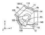
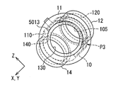
도 17 내지 도 19에서 도시한 바와 같이, 본 발명의 제3 실시 형태는 제1 실시 형태의 변형예이다. 제3 실시 형태의 에어 덕트(3013)의 중심축(La)은 X 방향에서 EGR 덕트(12)의 반대측을 향해 곡률 중심(Cv, Ch) 및 밸브체(10)의 회전축(Lv)으로부터 오프셋되는 위치(Sa)를 통해 연장되도록 설정된다. 제3 실시 형태의 혼합 덕트(3014)의 중심축(Lm)은 X 방향에서 EGR 덕트(12)의 반대측을 향해 곡률 중심(Cv, Ch) 및 밸브체(10)의 회전축(Lv)으로부터 오프셋되는 위치(Sm)를 통해 연장되도록 설정된다. 혼합 덕트(3014)의 중심축(Lm)의 오프셋 위치인 위치(Sm) 및 에어 덕트(3013)의 중심축(La)의 오프셋 위치인 위치(Sa)는 곡률 중심(Cv, Ch) 및 회전축(Lv)의 동일측{예를 들어, X 방향에서 EGR 덕트(12)의 반대측}에서 동일 거리로 곡률 중심(Cv, Ch) 및 밸브체(10)의 회전축(Lv)으로부터 오프셋된다. 즉, 위치(Sm) 및 위치(Sa)는 서로 일치한다{예를 들어, 위치(Sm)는 위치(Sa)와 같다}. 이러한 구조에 의해, 혼합 덕트(3014)의 중심축(Lm) 및 에어 덕트(3013)의 중심축(La)은 서로 실질적으로 동일 축상에 있다. 상술되지 않은 에어 덕트(3013) 및 혼합 덕트(3014)의 나머지 구조는 제1 실시 형태의 에어 덕트(13) 및 혼합 덕트(14)의 구조와 동일하다.As shown in Figs. 17 to 19, the third embodiment of the present invention is a modification of the first embodiment. The center axis La of the
제3 실시 형태에서도, 도 20a 내지 도 20c에 도시된 밸브체(10)의 완전 폐쇄 회전 위치(P1)로부터 도 21a 내지 도 21c에 도시된 밸브체(10)의 소정의 중간 회전 위치(P3)까지인 밸브체(10)의 회전 각도 범위(Rcm) 전체에 걸쳐, 밸브체(10)는 가상 에어 영역(Aa)으로부터 완전히 변위되어 에어 덕트(3013)의 완전 개방 상태를 유지한다. 또한, 제 3 실시 형태에서도, 밸브체(10)는 도 22a 내지 도 22c에 도시된 최대 제한 회전 위치(P5)로부터 최대 제한 회전 위치(P5) 전에 위치하는 회전 위치까지 밸브체(10)의 회전 각도 범위(Rss) 전체에 걸쳐 가상 EGR 영역(Ae)으로부터 완전히 변위되어 EGR 덕트(12)의 완전 개방 상태를 유지한다.In the third embodiment, the predetermined intermediate rotational position P3 of the
제3 실시 형태에 의하면, 에어 덕트(3013)는, 밸브체(10)의 회전축(Lv)에 대하여 EGR 덕트(12)와 반대측을 향해 밸브체(10)의 회전축(Lv)으로부터 오프셋되는 위치(Sa)를 통해 연장되는, 중심축(La)을 가진다. 그 결과, 에어 덕트(3013)는 EGR 덕트(12)로부터 가능한 많이 이격된다. 다시 말해, 에어 덕트(3013)는 제1 실시 형태의 에어 덕트(13)와 비교하면, EGR 덕트(12)로부터 더욱 이격된다. 그에 따라, 밸브체(10)의 완전 폐쇄 회전 위치(P1)로부터 밸브체(10)의 소정의 중간 회전 위치(P3)까지인, 밸브체(10)의 회전 각도 범위(Rcm)는 증가될 수 있다. 그러므로, 흡입 에어의 압력 손실을 감소시키는 요구 특성이 확실하게 만족될 수 있다.The
또한, 에어 덕트(3013)의 중심축(La)이 관통 연장하는 위치(Sa)와, 혼합 덕트(3014)의 중심축(Lm)이 관통 연장하는 위치(Sm)는, 밸브체(10)의 회전축(Lv)으로부터 회전축(Lv)의 동일측에 동일 거리만큼 오프셋된다. 이에 의해, 흡기 통로(31) 내에서는, 에어 덕트(3013)로부터 밸브 챔버(110) 내로 공급되고 혼합 덕트(3014)로 출력되는 흡입 에어의 압력 손실이 밸브체(10)의 완전 폐쇄 회전 위치(P1)로부터 밸브체(10)의 중간 회전 위치(P3)까지인 밸브체(10)의 회전 각도 범위(Rcm) 전체에 걸쳐 저감될 수 있다. 따라서, 제3 실시 형태의 저압 EGR 장치(1)는 흡입 에어의 압력 손실을 저감하는 요구 특성을 만족시킨다는 점에서 특히 효과적이다.The position Sa at which the center axis La of the
(제4 실시 형태)(Fourth Embodiment)
도 23 내지 도 25를 참조하면, 본 발명의 제4 실시 형태는 제1 실시 형태의 변형예이다. 제4 실시 형태의 EGR 덕트(4012)에 있어서, 곡률 중심(Cv, Ch)을 통해 연장하고 또한 밸브체(10)의 회전축(Lv)에 실질적으로 직교하는 EGR 덕트(4012)의 중심축(Le)은, 에어 덕트(13)의 중심축(La)과 중심축(Le) 사이에 둔각(θab)을 형성한다. 이에 의해, EGR 덕트(4012)의 중심축(Le)은 혼합 덕트(14)의 중심축(Lm)과 중심축(Le)과의 사이에 예각(θms)을 형성한다. 상술한 점 외의 EGR 덕트(4012)의 나머지 구조는, 제1 실시 형태의 EGR 덕트(12)의 구조와 실질적으로 동일하다.23 to 25, the fourth embodiment of the present invention is a modification of the first embodiment. In the
제4 실시 형태에서도, 도 26a 내지 도 26c에 도시된 밸브체(10)의 완전 폐쇄 회전 위치(P1)로부터 도 27a 내지 27c에 도시된 밸브체(10)의 중간 회전 위치(P3)까지 밸브체(10)의 회전 각도 범위(Rcm) 전체에 걸쳐 에어 덕트(13)의 완전 개방 상태를 유지하도록, 밸브체(10)는 가상 에어 영역(Aa)으로부터 완전히 변위된다. 또한, 제4 실시 형태에서도, 도 28a 내지 28c에 도시된 최대 제한 회전 위치(P5)로부터 최대 제한 회전 위치(P5) 앞에 위치하는 회전 위치까지 밸브체(10)의 회전 각도 범위(Rss) 전체에 걸쳐 EGR 덕트(4012)의 완전 개방 상태를 유지하도록 밸브체(10)는 가상 EGR 영역(Ae)으로부터 완전히 변위된다.26A to 26C to the intermediate rotational position P3 of the
제4 실시 형태에 따르면, 중심축(Le)을 갖는 EGR 덕트(4012)는 중심축(La)을 갖고 중심축(Le)에 대하여 둔각(θab)을 형성하는 에어 덕트(13)로부터 가능한 많이 이격된다. 다시 말해, EGR 덕트(4012)는 제1 실시 형태의 EGR 덕트(12)에 비해 에어 덕트(13)로부터 더욱 이격된다. 이에 의해, 밸브체(10)의 완전 폐쇄 회전 위치(P1)로부터 밸브체(10)의 소정의 중간 회전 위치(P3)까지인 밸브체(10)의 회전 각도 범위(Rcm)는 증가될 수 있다. 따라서, 흡입 에어의 압력 손실을 저감하는 요구 특성을 확실히 만족할 수 있다.According to the fourth embodiment, the
(제5 실시 형태)(Fifth Embodiment)
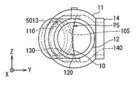
도 29 내지 도 31을 참조하면, 본 발명의 제5 실시 형태는 제1 실시 형태의 변형예이자 제4 실시 형태의 변형예이다. 제5 실시 형태의 에어 덕트(5013)에 있어서, 곡률 중심(Cv, Ch)을 통해 연장하고 또한 밸브체(10)의 회전축(Lv)에 실질적으로 직교하는 에어 덕트(5013)의 중심축(La)은, EGR 덕트(12)의 중심축(Le)과 중심축(La)과의 사이에 둔각(θab)을 형성한다. 상술한 점 외의 에어 덕트(5013)의 나머지 구조는, 제1 실시 형태의 에어 덕트(13)의 구조와 동일하다.29 to 31, the fifth embodiment of the present invention is a modification of the first embodiment and is a modification of the fourth embodiment. The central axis La of the
제5 실시 형태에서도, 에어 덕트(5013)는, 도 32a 내지 도 32c에 도시된 밸브체(10)의 완전 폐쇄 회전 위치(P1)로부터 도 33a 내지 도 33c에 도시된 밸브체(10)의 중간 회전 위치(P3)까지인 밸브체(10)의 회전 각도 범위(Rcm) 전체에 걸쳐 완전 개방된다. 이 때, 밸브체(10)는 밸브체(10)의 회전 각도 범위(Rcm) 전체에 걸쳐 에어 덕트(5013)의 완전 개방 상태를 유지하도록 가상 에어 영역(Aa)으로부터 완전히 변위된다. 제5 실시 형태에서도, EGR 덕트(12)는 도 34a 내지 도 34c에 도시된 최대 제한 회전 위치(P5)에서 완전 개방된다. 이 때, 밸브체(10)는 최대 제한 회전 위치(P5)에서 EGR 덕트(12)의 완전 개방 상태를 실현하도록 가상 EGR 영역(Ae)으로부터 완전히 변위된다.In the fifth embodiment as well, the
제5 실시 형태에서도, 도 32a 내지 도 32c에 도시된 밸브체(10)의 완전 폐쇄 회전 위치(P1)로부터 도 33a 내지 33c에 도시된 밸브체(10)의 중간 회전 위치(P3)까지 밸브체(10)의 회전 각도 범위(Rcm) 전체에 걸쳐 에어 덕트(5013)의 완전 개방 상태를 유지하도록, 밸브체(10)는 가상 에어 영역(Aa)으로부터 완전히 변위된다. 또한, 제5 실시 형태에서도, 도 34a 내지 도 34c에 도시된 최대 제한 회전 위치(P5)로부터 최대 제한 회전 위치(P5) 앞에 위치하는 회전 위치까지 밸브체(10)의 회전 각도 범위(Rss) 전체에 걸쳐 EGR 덕트(12)의 완전 개방 상태를 유지하도록 밸브체(10)는 가상 EGR 영역(Ae)으로부터 완전히 변위된다.In the fifth embodiment as well, from the fully closed rotational position P1 of the
제5 실시 형태에 따르면, 중심축(Le)을 갖는 EGR 덕트(12)는 중심축(La)을 갖고 중심축(Le)에 대하여 둔각(θab)을 형성하는 에어 덕트(5013)로부터 가능한 많이 이격된다. 다시 말해, EGR 덕트(12)는 제1 실시 형태의 EGR 덕트(12)에 비해 에어 덕트(5013)로부터 더욱 이격된다. 이에 의해, 밸브체(10)의 완전 폐쇄 회전 위치(P1)로부터 밸브체(10)의 소정의 중간 회전 위치(P3)까지인 밸브체(10)의 회전 각도 범위(Rcm)는 증가될 수 있다. 따라서, 흡입 에어의 압력 손실을 저감하는 요구 특성을 확실히 만족할 수 있다.According to the fifth embodiment, the
(다른 실시 형태)(Other Embodiments)
본 발명은 상기 실시 형태들을 참조로 하여 기술되었다. 그러나, 본 발명은 상기 실시 형태들에 한정되는 것은 아니고, 상기 실시 형태들은 본 발명의 원리 내에서 변형될 수 있다.The present invention has been described with reference to the above embodiments. However, the present invention is not limited to the above-described embodiments, and the above-described embodiments can be modified within the principles of the present invention.
구체적으로, 제1 변형예에서는, 도 35에 도시된 바와 같이, 제1 실시 형태의 혼합 덕트(14)와 동일한 혼합 덕트(3014)가 제3 실시 형태의 저압 EGR 장치(1)에 사용될 수 있다. 제2 변형예에서는, 도 36에 도시된 바와 같이, 제2 실시 형태의 EGR 덕트(2012) 및 제3 실시 형태의 에어 덕트(3013)가 함께 사용될 수 있다. 제2 변형예의 경우에, 도 36에 도시된 바와 같이, 제3 실시 형태의 혼합 덕트(3014)가 사용될 수 있다. 대안적으로는, 도시되지는 않았지만, 제1 실시 형태의 혼합 덕트(14)가 상술한 제1 변형예와 같은 경우에 사용될 수 있다.Specifically, in the first modification, as shown in Fig. 35, the
제3 변형예에서는, 도 37에 도시된 바와 같이, 제4 실시 형태의 EGR 덕트(4012) 및 제5 실시 형태의 에어 덕트(5013)가 함께 사용될 수 있다. 제4 변형예에서는, 두 아암부(101)로부터 반대측을 향해 각각 돌출되는 두 밸브 샤프트부(102)가 두 평면형 지지 표면(111)을 각각 형성하는 벽부에 의해 각각 형성되는 두 베어링부(112)에 의해 회전 가능하게 지지될 수 있다.In the third modification, the
제5 변형예에서는, 밸브체(10)의 회전 각도 범위(Rss)의 최대 제한 회전 위치(P5)가 아닌 부분에서, 밸브체(10)는 제1 내지 제5 실시 형태 중 어떠한 EGR 덕트(12, 2012, 4012)라도 부분적으로 폐쇄하도록 가상 EGR 영역(Ae)과 중첩될 수 있다. 제6 변형예에서는, 밸브체(10)의 회전 각도 범위(Rss)의 전체 범위에서, 밸브체(10)는 제1 내지 제5 실시 형태 중 어떠한 EGR 덕트(12, 2012, 4012)라도 부분적으로 폐쇄하도록 가상 EGR 영역(Ae)과 중첩될 수 있다.In the fifth modified example, the
제7 변형예에서는, 가솔린을 각각의 실린더(30)에서 연소되는 연료로 사용하는 가솔린 엔진이 본 발명에 적용되는 내연 기관(3)으로 사용될 수 있다. 제7 변형예의 경우에, 내연 기관(3)의 구체적인 구조는 제1 실시 형태에 기술된 구성에 한정되어서는 안된다.In the seventh modification, a gasoline engine using gasoline as fuel burned in each
Claims (8)
부분적 구면 형상인 볼록한 시일면(103)를 가지는 밸브체(10)로서, 볼록한 시일면(103)의 곡률 중심(Cv)을 통해 연장되는 회전축(Lv)을 중심으로 회전가능한, 밸브체(10);
밸브 하우징(11)으로서,
유동 합류부(310)를 형성하고 밸브체(10)를 수용하는 밸브 챔버(110)와;
부분적 구면 형상이며 밸브 챔버(110)에 노출되는 오목한 시일면(113)으로서, 볼록한 시일면(103)과 미끄럼 접촉하는, 오목한 시일면(113)를 갖는, 밸브 하우징(11);
유동 분기부(320)로부터 밸브 챔버(110)로 공급되는 EGR 가스를 안내하는 EGR 덕트(12, 2012, 4012);
유동 합류부(310)의 상류측에 위치하는 흡기 통로(31)의 통로부(311)를 형성하는 에어 덕트(13, 3013, 5013)로서, 흡입 에어를 밸브 챔버(110)로 안내하는, 에어 덕트(13, 3013, 5013); 및
유동 합류부(310)의 하류측에 위치하는 흡기 통로(31)의 통로부(312)를 형성하는 혼합 덕트(14, 3014)로서, EGR 가스 및 흡입 에어 중 적어도 하나가 밸브 챔버(110)로부터 혼합 덕트(14, 3014)를 통해 유출되는, 혼합 덕트(14, 3014)를 포함하고,
오목한 시일면(113)은 EGR 덕트(12, 2012, 4012)와 에어 덕트(13, 3013, 5013) 사이에 위치하고,
관형 형태이며, 흡입 에어가 밸브 챔버(110)로 유입되는 에어 덕트(13, 3013, 5013)의 유입구(130)와 EGR 가스 및 흡입 에어 중 적어도 하나가 밸브 챔버(110)로부터 유출되는 혼합 덕트(14, 3014)의 유출구(140) 사이를 최단 거리로 연결하는 가상 영역으로서, 가상 에어 영역(Aa)이 형성되고, 그리고
밸브체(10)는, 밸브체(10)가 EGR 덕트(12, 2012, 4012)를 완전 폐쇄하는 밸브체(10)의 완전 폐쇄 회전 위치(P1)로부터 밸브체(10)가 EGR 덕트(12, 2012, 4012)를 부분 개방하는 밸브체(10)의 소정의 중간 회전 위치(P3)까지 밸브체(10)의 회전 각도 범위(Rcm) 전체에 걸쳐, 가상 에어 영역(Aa)으로부터 변위되어 에어 덕트(13, 3013, 5013)를 완전 개방하는, 저압 EGR 장치.From the flow branching portion 320 of the exhaust passage 32 located on the downstream side of the turbine 20 of the turbocharger 2 provided in the internal combustion engine 3 to the upstream side of the compressor 21 of the turbocharger 2 Pressure EGR device for recirculating the EGR gas to the flow merging portion (310) of the intake passage (31) in which the EGR gas is mixed with the intake air guided to the intake passage (31)
A valve body (10) having a convex sealing surface (103) having a partial spherical shape is provided with a valve body (10) rotatable about a rotation axis (Lv) extending through a center of curvature (Cv) of a convex sealing surface (103) ;
As the valve housing 11,
A valve chamber (110) defining a flow merging portion (310) and receiving the valve body (10);
A valve housing (11) having a concave sealing surface (113) partially spherical in shape and exposed to the valve chamber (110) and having a concave sealing surface (113) slidingly contacting the convex sealing surface (103);
EGR ducts (12, 2012, 4012) for guiding EGR gas supplied from the flow branching section (320) to the valve chamber (110);
The air ducts 13, 3013 and 5013 forming the passage portion 311 of the intake passage 31 located on the upstream side of the flow merging portion 310 serve as air ducts for guiding the suction air to the valve chamber 110 Ducts (13, 3013, 5013); And
Wherein at least one of the EGR gas and the intake air is supplied from the valve chamber 110 to the mixing ducts 14 and 3014 forming the passage portion 312 of the intake passage 31 located on the downstream side of the flow merging portion 310, And a mixing duct (14, 3014) flowing out through the mixing duct (14, 3014)
The concave sealing surface 113 is located between the EGR ducts 12, 2012 and 4012 and the air ducts 13, 3013 and 5013,
And an inlet 130 of the air ducts 13, 3013 and 5013 into which the intake air is introduced into the valve chamber 110 and at least one of the EGR gas and the intake air flows out of the valve chamber 110 14, and 3014, the virtual air region Aa is formed as a virtual region that connects the outflow ports 140 of the first,
The valve body 10 is configured such that the valve body 10 is moved from the fully closed rotational position P1 of the valve body 10 which completely closes the EGR ducts 12, 2012 and 4012 to the EGR duct 12 , 2012, 4012 from the virtual air area Aa to the predetermined intermediate rotational position P3 of the valve body 10 partially opening the valve body 10, A low-pressure EGR device that completely opens the ducts (13, 3013, 5013).
EGR 덕트(2012)의 중심축(Le)은, 밸브체(10)의 회전축(Lv)에 대하여 에어 덕트(13)와 반대측에서 밸브체(10)의 회전축(Lv)으로부터 오프셋되는 위치(Se)를 통해 연장되는, 저압 EGR 장치.The method according to claim 1,
The center axis Le of the EGR duct 2012 is located at a position Se offset from the rotation axis Lv of the valve body 10 on the side opposite to the air duct 13 with respect to the rotation axis Lv of the valve body 10. [ Pressure EGR device.
에어 덕트(3013)의 중심축(La)은, 밸브체(10)의 회전축(Lv)에 대하여 EGR 덕트(12)와 반대측에서 밸브체(10)의 회전축(Lv)으로부터 오프셋되는 위치(Sa)를 통해 연장되는, 저압 EGR 장치.The method according to claim 1,
The center axis La of the air duct 3013 is located at a position Sa offset from the rotation axis Lv of the valve element 10 on the side opposite to the EGR duct 12 with respect to the rotation axis Lv of the valve element 10, Pressure EGR device.
에어 덕트(3013)의 중심축(La) 및 혼합 덕트(3014)의 중심축(Lm)은 밸브체(10)의 회전축(Lv)에 대하여 동일측에 동일 거리로 밸브체(10)의 회전축(Lv)으로부터 오프셋되는, 위치(Sa) 및 위치(Sm)을 통해 각각 연장되는, 저압 EGR 장치.The method of claim 3,
The center axis La of the air duct 3013 and the center axis Lm of the mixing duct 3014 are connected to the rotation axis Lv of the valve body 10 at the same distance to the rotation axis Lv of the valve body 10 Lv), respectively, through the position (Sa) and the position (Sm).
EGR 덕트(12, 4012)의 중심축(Le)과 에어 덕트(13, 5013)의 중심축(La) 사이에 둔각(θab)이 형성되는, 저압 EGR 장치.The method according to claim 1,
The obtuse angle? Ab is formed between the center axis Le of the EGR ducts 12 and 4012 and the center axis La of the air ducts 13 and 5013. The low-
관형 형태이며, EGR 가스가 밸브 챔버(110)로 유입되는 EGR 덕트(12, 2012, 4012)의 유입구(120)와 EGR 가스 및 흡입 에어 중 적어도 하나가 밸브 챔버(110)로부터 유출되는 혼합 덕트(14, 3014)의 유출구(140) 사이를 최단 거리로 연결하는 가상 영역으로서, 가상 EGR 영역(Ae)이 형성되고,
밸브체(10)는 가상 EGR 영역(Ae)으로부터 변위되어, 밸브체(10)에 의한 에어 덕트(13, 3013, 5013)의 유동 제한이 최대화되는 밸브체(10)의 최대 제한 위치(P5)에서 EGR 덕트(12, 2012, 4012)를 완전 개방하는, 저압 EGR 장치.6. The method according to any one of claims 1 to 5,
And the inlet 120 of the EGR ducts 12 2012 and 4012 into which the EGR gas flows into the valve chamber 110 and the mixing ducts 120 through which the EGR gas and the intake air flow out of the valve chamber 110 A virtual EGR region Ae is formed as a virtual region connecting the outflow ports 140 of the first and second exhaust ports 14 and 3014 at the shortest distance,
The valve body 10 is displaced from the imaginary EGR region Ae and the maximum restriction position P5 of the valve body 10 in which the flow restriction of the air ducts 13, 3013, 5013 by the valve body 10 is maximized, And the EGR ducts (12, 2012, 4012) are fully opened in the low-pressure EGR apparatus.
밸브체(10)는
볼록한 시일면(103)을 형성하는 시트부(100); 및
밸브체(10)의 회전축(Lv)의 반경 방향으로 시트부(100)로부터 연장되고, 에어 덕트(13, 3013, 5013)의 내경과 같거나 큰 거리로 밸브체(10)의 회전축(Lv)의 방향으로 서로 이격되는, 2개의 아암부(101)를 갖는, 저압 EGR 장치.6. The method according to any one of claims 1 to 5,
The valve body 10
A sheet portion 100 forming a convex sealing surface 103; And
The rotation axis Lv of the valve body 10 extends from the seat portion 100 in the radial direction of the rotation axis Lv of the valve body 10 and is equal to or greater than the inner diameter of the air ducts 13, Pressure EGR device having two arm portions 101 that are spaced apart from each other in the direction of the arrow.
밸브체(10)의 회전축(Lv)은 에어 덕트(13, 3013, 5013)의 중심축(La) 및 EGR 덕트(12, 2012, 4012)의 중심축(Le) 중 적어도 하나와 교차하고,
2개의 아암부(101) 중 적어도 하나는, 밸브 하우징(11)의 벽부를 통해 밸브체(10)의 회전축(Lv)을 따라 연장되며 전동 액츄에이터(15)에 의해 구동되는 밸브 샤프트부(102)에 고정되는, 저압 EGR 장치.
8. The method of claim 7,
The rotary shaft Lv of the valve body 10 intersects at least one of the central axis La of the air ducts 13,3013 and 5013 and the central axis Le of the EGR ducts 12,202 and 2012,
At least one of the two arm portions 101 includes a valve shaft portion 102 extending along the rotation axis Lv of the valve body 10 through the wall portion of the valve housing 11 and driven by the electric actuator 15, Pressure EGR device.
Applications Claiming Priority (2)
| Application Number | Priority Date | Filing Date | Title |
|---|---|---|---|
| JP2015126993A JP6468094B2 (en) | 2015-06-24 | 2015-06-24 | Low pressure EGR device |
| JPJP-P-2015-126993 | 2015-06-24 |
Related Child Applications (1)
| Application Number | Title | Priority Date | Filing Date |
|---|---|---|---|
| KR1020180172244A Division KR101978341B1 (en) | 2015-06-24 | 2018-12-28 | Low pressure egr device |
Publications (2)
| Publication Number | Publication Date |
|---|---|
| KR20170000799A true KR20170000799A (en) | 2017-01-03 |
| KR101935556B1 KR101935556B1 (en) | 2019-01-07 |
Family
ID=57537530
Family Applications (2)
| Application Number | Title | Priority Date | Filing Date |
|---|---|---|---|
| KR1020160078678A KR101935556B1 (en) | 2015-06-24 | 2016-06-23 | Low pressure egr device |
| KR1020180172244A KR101978341B1 (en) | 2015-06-24 | 2018-12-28 | Low pressure egr device |
Family Applications After (1)
| Application Number | Title | Priority Date | Filing Date |
|---|---|---|---|
| KR1020180172244A KR101978341B1 (en) | 2015-06-24 | 2018-12-28 | Low pressure egr device |
Country Status (3)
| Country | Link |
|---|---|
| JP (1) | JP6468094B2 (en) |
| KR (2) | KR101935556B1 (en) |
| DE (1) | DE102016109385A1 (en) |
Cited By (1)
| Publication number | Priority date | Publication date | Assignee | Title |
|---|---|---|---|---|
| KR20190122126A (en) * | 2018-04-19 | 2019-10-29 | 가부시키가이샤 덴소 | Valve device |
Families Citing this family (5)
| Publication number | Priority date | Publication date | Assignee | Title |
|---|---|---|---|---|
| JP6460012B2 (en) | 2016-03-03 | 2019-01-30 | 株式会社デンソー | Valve device |
| JP6933066B2 (en) | 2017-09-15 | 2021-09-08 | 株式会社デンソー | Valve device |
| CN110657021B (en) * | 2018-06-29 | 2020-11-20 | 潍柴动力股份有限公司 | Vortex front control valve and engine |
| JP7347326B2 (en) | 2020-05-26 | 2023-09-20 | 株式会社デンソー | EGR valve device |
| CN112459931A (en) * | 2020-11-10 | 2021-03-09 | 渭南美益特发动机减排技术有限公司 | EGR bypass valve with sealed radial surface |
Citations (10)
| Publication number | Priority date | Publication date | Assignee | Title |
|---|---|---|---|---|
| JP2010121551A (en) * | 2008-11-20 | 2010-06-03 | Denso Corp | Intake system for internal combustion engine |
| JP2011052604A (en) * | 2009-09-02 | 2011-03-17 | Denso Corp | Low-pressure egr device |
| EP2229550B1 (en) * | 2008-01-04 | 2011-10-12 | Continental Automotive GmbH | Exhaust gas recirculation valve for a motor vehicle |
| JP2011220296A (en) * | 2010-04-14 | 2011-11-04 | Denso Corp | Low-pressure egr device |
| WO2012081049A1 (en) * | 2010-12-13 | 2012-06-21 | 三菱電機株式会社 | Exhaust gas circulation valve |
| KR101207865B1 (en) * | 2003-12-19 | 2012-12-05 | 쿠퍼-스탠다드 오토모티브(도이칠랜드) 게엠베하 | Exhaust-gas recirculation valve |
| JP2013245602A (en) * | 2012-05-25 | 2013-12-09 | Mazda Motor Corp | Compression self-ignition gasoline engine |
| KR20140062633A (en) * | 2012-11-14 | 2014-05-26 | 주식회사 코렌스 | Bypass valve assembly for egr cooler |
| JP2014173462A (en) * | 2013-03-07 | 2014-09-22 | Fuji Heavy Ind Ltd | Air intake control system of engine |
| JP2015110948A (en) * | 2013-12-03 | 2015-06-18 | ヴァレオ システム テルミク | Control device for flow of intake gas and/or recirculation exhaust gas in internal combustion engine cylinder and corresponding intake module |
Family Cites Families (2)
| Publication number | Priority date | Publication date | Assignee | Title |
|---|---|---|---|---|
| JPS646355U (en) * | 1987-07-01 | 1989-01-13 | ||
| JP5287953B2 (en) * | 2011-04-27 | 2013-09-11 | 株式会社デンソー | Low pressure EGR device |
-
2015
- 2015-06-24 JP JP2015126993A patent/JP6468094B2/en active Active
-
2016
- 2016-05-23 DE DE102016109385.8A patent/DE102016109385A1/en not_active Ceased
- 2016-06-23 KR KR1020160078678A patent/KR101935556B1/en active IP Right Grant
-
2018
- 2018-12-28 KR KR1020180172244A patent/KR101978341B1/en active IP Right Grant
Patent Citations (10)
| Publication number | Priority date | Publication date | Assignee | Title |
|---|---|---|---|---|
| KR101207865B1 (en) * | 2003-12-19 | 2012-12-05 | 쿠퍼-스탠다드 오토모티브(도이칠랜드) 게엠베하 | Exhaust-gas recirculation valve |
| EP2229550B1 (en) * | 2008-01-04 | 2011-10-12 | Continental Automotive GmbH | Exhaust gas recirculation valve for a motor vehicle |
| JP2010121551A (en) * | 2008-11-20 | 2010-06-03 | Denso Corp | Intake system for internal combustion engine |
| JP2011052604A (en) * | 2009-09-02 | 2011-03-17 | Denso Corp | Low-pressure egr device |
| JP2011220296A (en) * | 2010-04-14 | 2011-11-04 | Denso Corp | Low-pressure egr device |
| WO2012081049A1 (en) * | 2010-12-13 | 2012-06-21 | 三菱電機株式会社 | Exhaust gas circulation valve |
| JP2013245602A (en) * | 2012-05-25 | 2013-12-09 | Mazda Motor Corp | Compression self-ignition gasoline engine |
| KR20140062633A (en) * | 2012-11-14 | 2014-05-26 | 주식회사 코렌스 | Bypass valve assembly for egr cooler |
| JP2014173462A (en) * | 2013-03-07 | 2014-09-22 | Fuji Heavy Ind Ltd | Air intake control system of engine |
| JP2015110948A (en) * | 2013-12-03 | 2015-06-18 | ヴァレオ システム テルミク | Control device for flow of intake gas and/or recirculation exhaust gas in internal combustion engine cylinder and corresponding intake module |
Non-Patent Citations (1)
| Title |
|---|
| 일본 재공표특허공보 WO2012/081049 1부. * |
Cited By (1)
| Publication number | Priority date | Publication date | Assignee | Title |
|---|---|---|---|---|
| KR20190122126A (en) * | 2018-04-19 | 2019-10-29 | 가부시키가이샤 덴소 | Valve device |
Also Published As
| Publication number | Publication date |
|---|---|
| DE102016109385A1 (en) | 2016-12-29 |
| KR20190003442A (en) | 2019-01-09 |
| JP6468094B2 (en) | 2019-02-13 |
| JP2017008870A (en) | 2017-01-12 |
| KR101935556B1 (en) | 2019-01-07 |
| KR101978341B1 (en) | 2019-05-14 |
Similar Documents
| Publication | Publication Date | Title |
|---|---|---|
| KR101978341B1 (en) | Low pressure egr device | |
| JP5635503B2 (en) | Assembly comprising a valve body and a seal structure, an assembly comprising a valve body, a seal and a pipe, and a seal structure for the assembly | |
| CN108779705B (en) | Supercharger and internal combustion engine | |
| JP5747483B2 (en) | Low pressure loop EGR device | |
| JP5986578B2 (en) | Exhaust turbocharger turbine | |
| CN106762239B (en) | Exhaust gas recirculation device | |
| US9732668B2 (en) | Discharge valve and associated device | |
| JP5699662B2 (en) | Exhaust device for internal combustion engine | |
| EP2103793A2 (en) | Flow rate control system for turbocharger | |
| US20180058340A1 (en) | Supercharged internal combustion engine with compressor, exhaust-gas recirculation arrangement and flap | |
| KR101399417B1 (en) | Bypass valve assembly for egr cooler | |
| WO2014109210A1 (en) | Supercharger | |
| US20110283977A1 (en) | Control apparatus for internal combustion engine with supercharger | |
| JP2008309125A (en) | Exhaust gas recirculation system for internal combustion engine | |
| WO2007089737A1 (en) | Combination variable geometry compressor, throttle valve, and recirculation valve | |
| JP6011501B2 (en) | Valve device | |
| US9708970B2 (en) | Housing for turbocharger | |
| JP2008261294A (en) | Control device for internal combustion engine with supercharger | |
| WO2013131214A1 (en) | Mixed variable flow volute | |
| JP6590033B2 (en) | Low pressure EGR device | |
| JP5742538B2 (en) | Exhaust device for internal combustion engine | |
| JP2011252421A (en) | Exhaust gas recirculation apparatus | |
| JP2022076179A (en) | Centrifugal compressor, turbocharger, and engine system | |
| US10619600B2 (en) | Recirculation valve | |
| KR20140111291A (en) | Exhaust gas recirculation system with a poppet valve |
Legal Events
| Date | Code | Title | Description |
|---|---|---|---|
| A201 | Request for examination | ||
| E902 | Notification of reason for refusal | ||
| E902 | Notification of reason for refusal | ||
| E701 | Decision to grant or registration of patent right |