JP6933066B2 - Valve device - Google Patents
Valve device Download PDFInfo
- Publication number
- JP6933066B2 JP6933066B2 JP2017177443A JP2017177443A JP6933066B2 JP 6933066 B2 JP6933066 B2 JP 6933066B2 JP 2017177443 A JP2017177443 A JP 2017177443A JP 2017177443 A JP2017177443 A JP 2017177443A JP 6933066 B2 JP6933066 B2 JP 6933066B2
- Authority
- JP
- Japan
- Prior art keywords
- valve member
- valve
- edge
- rotation
- valve device
- Prior art date
- Legal status (The legal status is an assumption and is not a legal conclusion. Google has not performed a legal analysis and makes no representation as to the accuracy of the status listed.)
- Active
Links
Images


Classifications
-
- F—MECHANICAL ENGINEERING; LIGHTING; HEATING; WEAPONS; BLASTING
- F16—ENGINEERING ELEMENTS AND UNITS; GENERAL MEASURES FOR PRODUCING AND MAINTAINING EFFECTIVE FUNCTIONING OF MACHINES OR INSTALLATIONS; THERMAL INSULATION IN GENERAL
- F16K—VALVES; TAPS; COCKS; ACTUATING-FLOATS; DEVICES FOR VENTING OR AERATING
- F16K1/00—Lift valves or globe valves, i.e. cut-off apparatus with closure members having at least a component of their opening and closing motion perpendicular to the closing faces
- F16K1/16—Lift valves or globe valves, i.e. cut-off apparatus with closure members having at least a component of their opening and closing motion perpendicular to the closing faces with pivoted closure-members
- F16K1/18—Lift valves or globe valves, i.e. cut-off apparatus with closure members having at least a component of their opening and closing motion perpendicular to the closing faces with pivoted closure-members with pivoted discs or flaps
- F16K1/20—Lift valves or globe valves, i.e. cut-off apparatus with closure members having at least a component of their opening and closing motion perpendicular to the closing faces with pivoted closure-members with pivoted discs or flaps with axis of rotation arranged externally of valve member
- F16K1/2014—Shaping of the valve member
-
- F—MECHANICAL ENGINEERING; LIGHTING; HEATING; WEAPONS; BLASTING
- F02—COMBUSTION ENGINES; HOT-GAS OR COMBUSTION-PRODUCT ENGINE PLANTS
- F02M—SUPPLYING COMBUSTION ENGINES IN GENERAL WITH COMBUSTIBLE MIXTURES OR CONSTITUENTS THEREOF
- F02M26/00—Engine-pertinent apparatus for adding exhaust gases to combustion-air, main fuel or fuel-air mixture, e.g. by exhaust gas recirculation [EGR] systems
- F02M26/02—EGR systems specially adapted for supercharged engines
- F02M26/04—EGR systems specially adapted for supercharged engines with a single turbocharger
- F02M26/06—Low pressure loops, i.e. wherein recirculated exhaust gas is taken out from the exhaust downstream of the turbocharger turbine and reintroduced into the intake system upstream of the compressor
-
- F—MECHANICAL ENGINEERING; LIGHTING; HEATING; WEAPONS; BLASTING
- F02—COMBUSTION ENGINES; HOT-GAS OR COMBUSTION-PRODUCT ENGINE PLANTS
- F02M—SUPPLYING COMBUSTION ENGINES IN GENERAL WITH COMBUSTIBLE MIXTURES OR CONSTITUENTS THEREOF
- F02M26/00—Engine-pertinent apparatus for adding exhaust gases to combustion-air, main fuel or fuel-air mixture, e.g. by exhaust gas recirculation [EGR] systems
- F02M26/13—Arrangement or layout of EGR passages, e.g. in relation to specific engine parts or for incorporation of accessories
- F02M26/17—Arrangement or layout of EGR passages, e.g. in relation to specific engine parts or for incorporation of accessories in relation to the intake system
- F02M26/21—Arrangement or layout of EGR passages, e.g. in relation to specific engine parts or for incorporation of accessories in relation to the intake system with EGR valves located at or near the connection to the intake system
-
- F—MECHANICAL ENGINEERING; LIGHTING; HEATING; WEAPONS; BLASTING
- F02—COMBUSTION ENGINES; HOT-GAS OR COMBUSTION-PRODUCT ENGINE PLANTS
- F02M—SUPPLYING COMBUSTION ENGINES IN GENERAL WITH COMBUSTIBLE MIXTURES OR CONSTITUENTS THEREOF
- F02M26/00—Engine-pertinent apparatus for adding exhaust gases to combustion-air, main fuel or fuel-air mixture, e.g. by exhaust gas recirculation [EGR] systems
- F02M26/51—EGR valves combined with other devices, e.g. with intake valves or compressors
-
- F—MECHANICAL ENGINEERING; LIGHTING; HEATING; WEAPONS; BLASTING
- F02—COMBUSTION ENGINES; HOT-GAS OR COMBUSTION-PRODUCT ENGINE PLANTS
- F02M—SUPPLYING COMBUSTION ENGINES IN GENERAL WITH COMBUSTIBLE MIXTURES OR CONSTITUENTS THEREOF
- F02M26/00—Engine-pertinent apparatus for adding exhaust gases to combustion-air, main fuel or fuel-air mixture, e.g. by exhaust gas recirculation [EGR] systems
- F02M26/65—Constructional details of EGR valves
- F02M26/70—Flap valves; Rotary valves; Sliding valves; Resilient valves
-
- F—MECHANICAL ENGINEERING; LIGHTING; HEATING; WEAPONS; BLASTING
- F02—COMBUSTION ENGINES; HOT-GAS OR COMBUSTION-PRODUCT ENGINE PLANTS
- F02M—SUPPLYING COMBUSTION ENGINES IN GENERAL WITH COMBUSTIBLE MIXTURES OR CONSTITUENTS THEREOF
- F02M26/00—Engine-pertinent apparatus for adding exhaust gases to combustion-air, main fuel or fuel-air mixture, e.g. by exhaust gas recirculation [EGR] systems
- F02M26/65—Constructional details of EGR valves
- F02M26/71—Multi-way valves
-
- F—MECHANICAL ENGINEERING; LIGHTING; HEATING; WEAPONS; BLASTING
- F16—ENGINEERING ELEMENTS AND UNITS; GENERAL MEASURES FOR PRODUCING AND MAINTAINING EFFECTIVE FUNCTIONING OF MACHINES OR INSTALLATIONS; THERMAL INSULATION IN GENERAL
- F16K—VALVES; TAPS; COCKS; ACTUATING-FLOATS; DEVICES FOR VENTING OR AERATING
- F16K1/00—Lift valves or globe valves, i.e. cut-off apparatus with closure members having at least a component of their opening and closing motion perpendicular to the closing faces
- F16K1/16—Lift valves or globe valves, i.e. cut-off apparatus with closure members having at least a component of their opening and closing motion perpendicular to the closing faces with pivoted closure-members
- F16K1/18—Lift valves or globe valves, i.e. cut-off apparatus with closure members having at least a component of their opening and closing motion perpendicular to the closing faces with pivoted closure-members with pivoted discs or flaps
- F16K1/20—Lift valves or globe valves, i.e. cut-off apparatus with closure members having at least a component of their opening and closing motion perpendicular to the closing faces with pivoted closure-members with pivoted discs or flaps with axis of rotation arranged externally of valve member
- F16K1/2042—Special features or arrangements of the sealing
- F16K1/2057—Special features or arrangements of the sealing the sealing being arranged on the valve seat
-
- F—MECHANICAL ENGINEERING; LIGHTING; HEATING; WEAPONS; BLASTING
- F16—ENGINEERING ELEMENTS AND UNITS; GENERAL MEASURES FOR PRODUCING AND MAINTAINING EFFECTIVE FUNCTIONING OF MACHINES OR INSTALLATIONS; THERMAL INSULATION IN GENERAL
- F16K—VALVES; TAPS; COCKS; ACTUATING-FLOATS; DEVICES FOR VENTING OR AERATING
- F16K11/00—Multiple-way valves, e.g. mixing valves; Pipe fittings incorporating such valves
- F16K11/02—Multiple-way valves, e.g. mixing valves; Pipe fittings incorporating such valves with all movable sealing faces moving as one unit
- F16K11/06—Multiple-way valves, e.g. mixing valves; Pipe fittings incorporating such valves with all movable sealing faces moving as one unit comprising only sliding valves, i.e. sliding closure elements
- F16K11/072—Multiple-way valves, e.g. mixing valves; Pipe fittings incorporating such valves with all movable sealing faces moving as one unit comprising only sliding valves, i.e. sliding closure elements with pivoted closure members
- F16K11/076—Multiple-way valves, e.g. mixing valves; Pipe fittings incorporating such valves with all movable sealing faces moving as one unit comprising only sliding valves, i.e. sliding closure elements with pivoted closure members with sealing faces shaped as surfaces of solids of revolution
Description
本発明は、弁装置に関する。 The present invention relates to a valve device.
従来、流体を流通可能な流路上に設けられ、当該流体の流れを制御可能な弁装置が知られている。弁装置は、流路を有する弁ハウジング、及び、弁ハウジング内において回転可能な弁部材を有する。例えば、特許文献1には、内燃機関の吸気通路上に設けられる弁ハウジング、及び、弁ハウジングが有する円筒状の弁室に回転可能に収容されている弁部材を備える低圧EGR装置が記載されている。 Conventionally, a valve device that is provided on a flow path through which a fluid can flow and can control the flow of the fluid is known. The valve device has a valve housing having a flow path and a valve member that is rotatable in the valve housing. For example, Patent Document 1 describes a low-pressure EGR device including a valve housing provided on an intake passage of an internal combustion engine and a valve member rotatably housed in a cylindrical valve chamber of the valve housing. There is.
低圧EGR装置では、内燃機関が排出し吸気に還流される排気の流量を弁ハウジングに対する弁部材の回転角度によって制御する。排気には水分が含まれており、環境条件によっては氷となって弁ハウジングと弁部材とを固着する場合がある。このため、弁部材の形状や弁ハウジングへの組み付けにおけるずれによって弁ハウジングの開口の縁部に当接する弁部材のシール部の回転軸と弁ハウジングにおける弁部材の回転軸とが同軸でないと弁部材が回転できないおそれがある。 In the low-pressure EGR device, the flow rate of the exhaust gas discharged from the internal combustion engine and returned to the intake air is controlled by the rotation angle of the valve member with respect to the valve housing. Moisture is contained in the exhaust gas, and depending on the environmental conditions, it may become ice and fix the valve housing and the valve member. Therefore, the valve member must be coaxial with the rotation axis of the seal portion of the valve member that comes into contact with the edge of the opening of the valve housing due to the shape of the valve member or the deviation in assembly to the valve housing. May not rotate.
本発明は、上述の点に鑑みてなされたものであり、その目的は、流路を確実に連通または遮断可能な弁装置を提供することにある。 The present invention has been made in view of the above points, and an object of the present invention is to provide a valve device capable of reliably communicating or shutting off a flow path.
本発明の弁装置は、弁ハウジング(10)、及び、弁部材(20,40,50,60,70)を備える。
弁ハウジングは、流体を流通可能な複数の流路(12,13,14)、及び、複数の流路を連通する連通空間(110)を有する。
弁部材は、弁ハウジングに対して相対回転可能に設けられる。弁部材は、複数の流路の一の流路(14)と連通空間との間に形成されている一の流路の開口の縁部に当接すると当該一の流路と連通空間とを遮断する。
本発明の弁装置では、弁部材が開口の縁部から離間した状態から開口の縁部に当接している状態となるよう弁部材が回転する方向を閉弁回転方向とする。
The valve device of the present invention includes a valve housing (10) and valve members (20, 40, 50, 60, 70).
The valve housing has a plurality of flow paths (12, 13, 14) through which a fluid can flow, and a communication space (110) for communicating the plurality of flow paths.
The valve member is provided so as to be rotatable relative to the valve housing. When the valve member comes into contact with the edge of the opening of the one flow path formed between the one flow path (14) of the plurality of flow paths and the communication space, the valve member makes the one flow path and the communication space come into contact with each other. Cut off.
In the valve device of the present invention, the direction in which the valve member rotates from the state in which the valve member is separated from the edge of the opening to the state in which the valve member is in contact with the edge of the opening is defined as the valve closing rotation direction .
本発明の第一態様による弁装置では、弁部材(20,40,50)の径方向外側部(21,41,51)の少なくとも一部の回転軸(RA20,RA40,RA50)に沿う方向の幅(Li11,Li12,Li13,Li21,Li22,Li23,Li31,Li32,Li33)は、閉弁回転方向に向かうにしたがって狭くなる。
本発明の第二態様による弁装置では、弁部材(20,60)の径方向外側の縁部(225,235,625)は、回転方向において段差なく曲線状に延びており、弁部材の回転軸上の点(P25,P65)から弁部材の径方向外側の縁部までの距離(Ri221,Ri222,Ri223,Ri421,Ri422,Ri423)は、閉弁回転方向に向かうにしたがって全範囲で単調減少する。
In the valve device according to the first aspect of the present invention, the valve member (20, 40, 50) is oriented in the direction along at least a part of the rotation axis (RA20, RA40, RA50) of the radial outer portion (21, 41, 51). The widths (Li11, Li12, Li13, Li21, Li22, Li23, Li31, Li32, Li33) become narrower toward the valve closing rotation direction.
The valve device according to the second aspect of the present invention, the radially outer edge of the valve member (20,6 0) (225,235,62 5) extends without any step curved in the rotation direction, the valve member distance from the point on the round guinea (P25, P6 5) to the radially outer edge of the valve member (Ri221, Ri222, Ri223, Ri421 , Ri422, Ri42 3) is toward the valve closing direction of rotation It decreases monotonically in the entire range .
本発明の第一態様による弁装置では、径方向外側部の少なくとも一部の回転軸に沿う方向の幅は、閉弁回転方向に向かうにしたがって狭くなっている。これにより、弁部材と開口の縁部とが当接している状態において弁部材の回転軸に沿う方向のいずれかに弁ハウジングと弁部材とを固着する氷が生成されていても、弁部材は、閉弁回転方向とは反対の方向に回転するとき氷から離れる方向に移動することができる。したがって、本発明の第一態様による弁装置は、弁部材を確実に回転し一の流路と連通空間とを連通することができるため、流路を確実に連通または遮断することができる。 In the valve device according to the first aspect of the present invention, the width of the radial outer portion along the rotation axis of at least a part thereof becomes narrower toward the valve closing rotation direction. As a result, even if ice is generated to fix the valve housing and the valve member in any direction along the rotation axis of the valve member in a state where the valve member and the edge of the opening are in contact with each other, the valve member is still in contact with the valve member. , When rotating in the direction opposite to the valve closing rotation direction, it can move away from the ice. Therefore, in the valve device according to the first aspect of the present invention, the valve member can be reliably rotated to communicate with one flow path and the communication space, so that the flow path can be reliably communicated or cut off.
本発明の第二態様による弁装置では、弁部材の径方向外側の縁部は回転方向において段差なく曲線状に延びており、弁部材の回転軸上の点から弁部材の径方向外側の縁部までの距離は、閉弁回転方向に向かうにしたがって全範囲で単調減少する。これにより、弁部材と開口の縁部とが当接している状態において弁部材の径方向外側に弁ハウジングと弁部材とを固着する氷が生成されていても、弁部材は、閉弁回転方向とは反対の方向に回転するとき氷から離れる方向に移動することができる。したがって、本発明の第二態様による弁装置は、弁部材を確実に回転し一の流路と連通空間とを連通することができるため、流路を確実に連通または遮断することができる。 In accordance with the valve device a second aspect of the present invention, the radially outer valve member edge extends without any step curved in the rotation direction, from a point on the valve member round guinea radially outer valve member The distance to the edge decreases monotonically in the entire range toward the valve closing rotation direction . As a result, even if ice is generated to fix the valve housing and the valve member on the radial outer side of the valve member in a state where the valve member and the edge of the opening are in contact with each other, the valve member is kept in the valve closing rotation direction. When rotating in the opposite direction, it can move away from the ice. Therefore, in the valve device according to the second aspect of the present invention, the valve member can be reliably rotated to communicate with one flow path and the communication space, so that the flow path can be reliably communicated or cut off.
以下、複数の実施形態を図面に基づいて説明する。 Hereinafter, a plurality of embodiments will be described with reference to the drawings.
(第一実施形態)
第一実施形態による弁装置1を図1〜図11に基づいて説明する。弁装置1は、燃料を燃焼することによって駆動力を発生するエンジンシステム90に適用される。
最初に、図1を用いてエンジンシステム90を説明する。エンジンシステム90は、エンジン91、吸気系92、排気系93、過給器94、排気還流系95などを備えている。なお、エンジン91は、シリンダ911内にピストン912を収容して燃焼室910を形成する周知の構造である。
(First Embodiment)
The valve device 1 according to the first embodiment will be described with reference to FIGS. 1 to 11. The valve device 1 is applied to an
First, the
吸気系92は、外気からエンジン91に空気を供給する。吸気系92は、吸気管921、吸気マニホールド922、エアクリーナ923、インタークーラ924、及び、スロットル925などを有する。以下、エンジン91に供給される空気を吸入空気と呼ぶ。
The
吸気管921は、燃焼室910に吸入空気を導くための配管であり、吸気通路920を有する。吸気管921の一端は、外気に開放され、他端は、吸気マニホールド922に接続されている。
吸気マニホールド922は、吸気管921の他端とエンジン91とに接続されている。吸気マニホールド922は、シリンダ911の数と同数の通路に分岐する構造を有する。
エアクリーナ923は、大気から取り込んだ空気から異物を除去する。
インタークーラ924は、過給器94のコンプレッサ941により圧縮されて昇温した吸入空気を冷却する。
スロットル925は、エンジン91の吸気量を調整する。スロットル925は、電子制御ユニット(以下、「ECU」という)96と電気的に接続されている。
The
The
The
The
The
排気系93は、エンジン91が排出する排気を外気へ放出する。排気系93は、排気管931、排気マニホールド932、及び、排気浄化ユニット933を有する。
排気管931は、エンジン91の排気を大気に導くための配管であり、排気通路930を有する。
排気マニホールド932は、排気管931の一端とエンジン91とに接続している。排気マニホールド932は、シリンダ911の数と同数の通路が合流する構造を有する。
排気浄化ユニット933は、排気管931に設けられている。排気浄化ユニット933は、排気に含まれる炭化水素を分解したり、微粒子状物質を捕捉したりする。
The
The
The
The
過給器94は、排気のエネルギーを利用して吸気管921内で吸入空気を圧縮し燃焼室910に加圧した吸入空気を過給する。過給器94は、コンプレッサ941、タービン942、及び、シャフト943を有する。
コンプレッサ941は、吸気通路920においてエアクリーナ923とインタークーラ924との間に配置されている。コンプレッサ941は、吸入空気を圧縮可能である。
タービン942は、排気通路930において排気マニホールド932と排気浄化ユニット933との間に配置されている。タービン942は、排気のエネルギーにより回転駆動される。
シャフト943は、コンプレッサ941とタービン942とを連結している。コンプレッサ941とタービン942とは、シャフト943により同期して回転する。
The
The
The
The
排気還流系95は、タービン942を通過した後の排気を吸気通路920に還流する。吸気通路920に還流された排気は、エアクリーナ923を経由した空気とともに燃焼室910に供給される。排気還流系95は、EGR管951、EGRクーラ952、及び、弁装置1を備える。
The exhaust
EGR管951は、排気管931の排気浄化ユニット933の下流側と、吸気管921のコンプレッサ941の上流側とを接続する。EGR管951は、タービン942を通過した後の排気をコンプレッサ941による圧縮前の空気に還流するEGR通路950を有する。
EGRクーラ952は、EGR管951に設けられている。EGRクーラ952は、EGR通路950を通る気体を冷却する。
弁装置1は、EGR管951と吸気管921とが接続されている箇所に設けられている。弁装置1は、EGR通路950を通じて吸気通路920に流入する気体の流量を増減する。弁装置1は、ECU96と電気的に接続されている。
The EGR pipe 951 connects the downstream side of the
The
The valve device 1 is provided at a position where the EGR pipe 951 and the
ECU96は、演算部としてのCPU、ならびに、記憶部としてのRAM及びROM等を有するマイクロコンピュータ等から構成されている。ECU96は、エンジンシステム90を搭載する車両や装置の駆動状況、当該車両や装置を操作する操作者の操作内容に応じて、スロットル925や弁装置1の駆動を制御する。
The
次に、弁装置1の詳細な構成について、図2〜図10に基づいて説明する。
弁装置1は、円筒状の弁部材を回転駆動することによって流体の通路の開度を増減可能なロータリー式の弁である。弁装置1は、EGR通路950の吸気通路920に対する開度を増減可能である。弁装置1は、弁ハウジング10、弁部材20、上シャフト25、下シャフト26、駆動部35、ギヤ部37などを備える。
Next, the detailed configuration of the valve device 1 will be described with reference to FIGS. 2 to 10.
The valve device 1 is a rotary valve capable of increasing or decreasing the opening degree of the fluid passage by rotationally driving a cylindrical valve member. The valve device 1 can increase or decrease the opening degree of the EGR passage 950 with respect to the
弁ハウジング10は、ケーシング111、センサカバー112、ボトムカバー113、筒部材16、「開口の縁部」としてのハウジング側シール部材17などを有する。
ケーシング111は、アルミニウムなどの金属材料から弁部材20を収容可能に形成されている。ケーシング111は、吸気通路920とEGR通路950との合流部分を形成する。具体的には、ケーシング111は、図5,6に示すように、「連通空間」としての弁室110、「流路」としての上流側流路12、「流路」としての下流側流路13、及び、「一の流路」としての収容空間14を有する。
The
The
弁室110は、弁部材20を回転可能に収容可能なよう形成されている。
上流側流路12は、弁室110に連通するよう形成されている。上流側流路12は、エアクリーナ923に連通する。
下流側流路13は、上流側流路12とは別に弁室110に連通するよう形成されている。下流側流路13は、上流側流路12と同軸上に形成されている。下流側流路13は、インタークーラ924に連通する。
収容空間14は、上流側流路12及び下流側流路13とは別に弁室110に連通するよう形成されている。収容空間14は、ハウジング側シール部材17が組み付けられた筒部材16を収容可能に形成されている。収容空間14は、EGR通路950に連通する。
The
The upstream
The
The
ケーシング111は、図4に示すように、弁室110を形成する壁体114を有する。壁体114は、上シャフト25が挿通される通孔101を有する。壁体114の通孔101を形成する内壁には、軸受102及びオイルシール103が設けられている。軸受102は、上シャフト25を回転可能に支持する。オイルシール103は、弁室110の気体が通孔101を通って弁室110の外部に流出することを防止する。
As shown in FIG. 4, the
センサカバー112は、ケーシング111の壁体114から見て弁室110とは反対側に設けられる。センサカバー112は、ケーシング111とともに駆動部35やギヤ部37などを収容可能な収容空間370を形成する。
The
ボトムカバー113は、ケーシング111のセンサカバー112が設けられる側とは反対側に設けられる。ボトムカバー113は、ケーシング111とともに弁室110を形成する。ボトムカバー113は、下シャフト26を挿入可能な通孔104を有する。通孔104を形成するボトムカバー113の内壁には、軸受105が設けられる。
The
筒部材16は、ケーシング111とは別に設けられる部材である。筒部材16は、フランジ部161、第一側壁部162、及び、第二側壁部163を有する。筒部材16は、ステンレスから形成されている。
The
フランジ部161は、略環状に形成されている部位である。筒部材16が収容空間14に収容されるとき、フランジ部161は、図5,6に示すように、収容空間14を形成する内壁に設けられている段差面141に当接する。このとき、筒部材16は、環状のリング191をケーシング111に圧入することでケーシング111に対して固定される。リング191は、ウェーブワッシャ192を介してフランジ部161を段差面141に押し当てている。
The
第一側壁部162及び第二側壁部163は、フランジ部161の段差面141に当接する端面からフランジ部161の軸方向に沿って延びるよう形成されている。第一側壁部162及び第二側壁部163は、円筒の側壁の一部と同じ形状となるよう形成されている。第一実施形態では、第一側壁部162と第二側壁部163とは、中心角が180度となるよう形成されている。第一側壁部162は、フランジ部161の軸方向に沿って延びる高さが、第二側壁部163のフランジ部161の軸方向に沿って延びる高さに比べ低くなるよう形成されている。
The first
ハウジング側シール部材17は、第一被覆部171、第一シールリップ部172、第二被覆部173、及び、第二シールリップ部174を有する。ハウジング側シール部材17は、ゴムなどの弾性材料から略筒状に形成されている。
The housing-
第一被覆部171は、第一側壁部162の径方向内側、径方向外側、及び、フランジ部161側とは反対側の端部を覆うよう形成されている。
第一シールリップ部172は、第一被覆部171のフランジ部161側とは反対側の端部を覆う部位に設けられているリップ状の部位である。第一シールリップ部172は、第一被覆部171が第一側壁部162を覆うよう設けられるとき、図5,6,7に示すように、第一側壁部162の径外方向、すなわち、フランジ部161の径外方向に突出するよう形成される。
The
The first
第二被覆部173は、第二側壁部163の径方向内側、径方向外側、フランジ部161側とは反対側の端部、及び、第二側壁部163の第一側壁部162と接続する部位の端面を覆うよう形成されている。第二被覆部173は、図7に示すように、第一側壁部162と接続する部位の端面を覆う部位にハウジング側シール部材17の周方向に向くシール面175,176を有する。シール面175,176は、第一シールリップ部172と接続している。
第二シールリップ部174は、第二被覆部173のフランジ部161側とは反対側の端部を覆う部位に設けられているリップ状の部位である。第二シールリップ部174は、第二被覆部173が第二側壁部163を覆うよう設けられるとき、図7に示すように、第二側壁部163の径内方向、すなわち、フランジ部161の径内方向に突出するよう形成される。第二シールリップ部174は、シール面175,176に接続している。
以下、図7に示すように、ハウジング側シール部材17と筒部材16とが組み合わされた部材を筒体15という。
The
The second
Hereinafter, as shown in FIG. 7, a member in which the housing
弁部材20は、「弁部材の径方向外側部」としての弁部材側シール部21、上アーム22、及び、下アーム23を有する。弁部材20は、高い耐熱性を有する樹脂材料、例えば、ポリフェニレンスルフィドから形成されている。弁部材20は、図5,6に示すように、弁室110に収容され、弁ハウジング10に対して相対回転可能に設けられている(図5の実線矢印R5及び図6の実線矢印R6参照)。ここで、弁部材20の回転方向について、便宜的に、図5の状態から図6の状態となるよう回転する方向を「閉弁回転方向」としての「EGR通路遮断方向」といい、図6の状態から図5の状態となるよう回転する方向を「閉弁回転方向とは反対方向」としての「EGR通路開放方向」という。
The
弁部材側シール部21は、弁部材20の回転軸RA20から見て弁部材20の径方向外側に設けられている。弁部材側シール部21は、ハウジング側シール部材17に当接可能な外壁面211が円筒の径方向外側の壁面の一部と同じ形状となるよう形成されている。外壁面211は、図5、6に示すように、シール面212、213、及び、接続シール面214,215を有する。
The valve member
シール面212、213は、外壁面211において弁部材側シール部21の周方向に向かうよう形成されている。
シール面212は、外壁面211においてEGR通路遮断方向に向かうよう形成されている。シール面212は、円筒の径方向外側の側壁の内壁面の一部と同じ形状となっている。第一実施形態では、シール面212は、中心角が180度の半円筒形となっている。シール面212は、半径がシール面213の半径に比べ大きくなるよう形成されている。シール面212は、第一シールリップ部172に当接可能に形成されている。
シール面213は、外壁面211においてEGR通路遮断方向に向かうよう形成されている。シール面213は、円筒の径方向外側の側壁の外壁面の一部と同じ形状となっている。第一実施形態では、シール面213は、中心角が180度の半円筒形となっている。シール面213は、第二シールリップ部174に当接可能に形成されている。
シール面212を含む仮想円筒面とシール面213を含む仮想円筒面とは同軸上に中心軸を有する。当該中心軸は、弁部材20の回転軸RA20に直交する。
The seal surfaces 212 and 213 are formed on the
The sealing
The sealing
The virtual cylindrical surface including the sealing
接続シール面214、215は、外壁面211においてEGR通路遮断方向に向かうよう形成されている。接続シール面214、215は、シール面212、213に直交するよう形成されている。接続シール面214、215の法線は、平行移動すると弁部材20の回転軸RA20に直交することが可能である。
接続シール面214は、図8に示すように、シール面212とシール面213とが接続する箇所のうち上アーム22側に位置する。接続シール面214は、シール面175に当接可能に形成されている。
接続シール面215は、図8に示すように、シール面212とシール面213とが接続する箇所のうち下アーム23側に位置する。接続シール面215は、シール面176に当接可能に形成されている。
The connection seal surfaces 214 and 215 are formed on the
As shown in FIG. 8, the
As shown in FIG. 8, the
第一実施形態では、弁部材側シール部21は、EGR通路遮断方向に向かうにしたがって回転軸RA20に沿う方向の長さが短くなるよう形成されている。そこで、弁部材側シール部21の形状について図9に基づいて説明する。図9は、弁部材20の側面図を示している。図9には、弁部材20が弁ハウジング10に組み付けられているときの回転方向を実線矢印で示す。
In the first embodiment, the valve member
具体的には、図9に示すように、弁部材側シール部21は、EGR通路遮断方向側に位置する端部216の回転軸RA20に沿う方向の長さLi11がEGR通路開放方向側に位置する端部217の回転軸RA20に沿う方向の長さLi12に比べ短くなっている。また、弁部材側シール部21は、端部216と端部217とのそれぞれから等距離に位置する中間部218の回転軸RA20に沿う方向の長さLi13が、端部216の長さLi11に比べ長く、かつ、端部217の長さLi12に比べ短い。第一実施形態では、長さLi11,Li12,Li13は、以下の関係式(1)が成立する。
Li12−Li13=Li13−Li11 ・・・(1)
第一実施形態では、式(1)の右辺及び左辺の値は、比較的小さい値となっている。
弁部材20は、上アーム22の弁部材側シール部21と接続する「弁部材の径方向外側の縁部」としての縁部225及び下アーム23の弁部材側シール部21と接続する「弁部材の径方向外側の縁部」としての縁部235は、図9に示す側面図において直線状に形成されている。
Specifically, as shown in FIG. 9, in the valve member
Li12-Li13 = Li13-Li11 ... (1)
In the first embodiment, the values on the right side and the left side of the equation (1) are relatively small values.
The
弁部材20がEGR通路開放方向に回転し図5に示す状態となると、弁室110に対して上流側流路12を最小限に絞りつつ、弁室110に対して収容空間14に連通するEGR通路950を最大限に開放する。
弁部材20がEGR通路遮断方向に回転し図6に示す状態になると、第一シールリップ部172がシール面212に当接し、第二シールリップ部174がシール面213に当接する。また、シール面175,176のそれぞれは、接続シール面214,215のそれぞれに当接する。これにより、弁室110とEGR通路950とを遮断しつつ、弁室110に対して上流側流路12を最大限に開放する。
When the
When the
また、第一実施形態では、弁部材20の回転角度を制御することによって、EGR通路950の吸気通路920に対する開度とともに吸気通路920の開度を増減することが可能である。これにより、吸気通路920の負圧の大きさを制御することが可能なため、例えば、エンジン91で生じる負圧を利用する代わりに弁部材20の回転角度を制御することによって吸気通路920に流入する排気量を制御することが可能である。
Further, in the first embodiment, by controlling the rotation angle of the
上アーム22は、弁部材側シール部21の回転軸RA20に沿う方向の端部のうちセンサカバー112側の端部に設けられている。上アーム22は、上接続部221、及び、上締結部222を有する。
上接続部221は、弁部材側シール部21のセンサカバー112側の端部に設けられている。上接続部221は、図4,8に示すように、外壁面223が回転軸RA20に対して傾斜するよう形成されている。具体的には、弁部材側シール部21側の端部から上締結部222側の端部に向かうにしたがって回転軸RA20に近づくよう形成されている。外壁面223には、撥水性の膜が形成されている。
上締結部222は、上接続部221の弁部材側シール部21に接続する側とは反対側の端部から弁部材20の回転軸RA20に向かう方向、すなわち、略筒状の弁部材20の径内方向に延びるよう形成されている部位である。上締結部222は、上接続部221に接続する側とは反対側の端部に上シャフト25が圧入される通孔224を有する。
なお、図4には、便宜的に、弁部材側シール部21と上接続部221、及び、上接続部221と上締結部222との境界線を二点鎖線VLI11,VL12で示す。
The
The upper connecting
The
In FIG. 4, for convenience, the boundary lines between the valve member
下アーム23は、弁部材側シール部21の回転軸RA20に沿う方向の端部のうちボトムカバー113側の端部に設けられている。下アーム23は、下接続部231、及び、下締結部232を有する。
下接続部231は、弁部材側シール部21のボトムカバー113側の端部に設けられている。下接続部231は、図4に示すように、外壁面233が回転軸RA20に対して傾斜するよう形成されている。具体的には、弁部材側シール部21側の端部から下締結部232側の端部に向かうにしたがって回転軸RA20に近づくよう形成されている。外壁面233には、撥水性の膜が形成されている。
下締結部232は、下接続部231の弁部材側シール部21に接続する側とは反対側の端部から弁部材20の径内方向に延びるよう形成されている部位である。下締結部232は、下接続部231に接続する側とは反対側の端部に下シャフト26が圧入される通孔234を有する。
なお、図4には、便宜的に、弁部材側シール部21と下接続部231、及び、下接続部231と下締結部232との境界線を二点鎖線VL13,VL14で示す。
The
The lower connecting
The
In FIG. 4, for convenience, the boundary lines between the valve member
第一実施形態では、上アーム22及び下アーム23は、弁部材20の径方向の長さがEGR通路遮断方向に向かうにしたがって短くなるよう形成されている。そこで、上アーム22の形状について図10に基づいて説明する。図10は、弁ハウジング10に組み付けられている弁部材20のセンサカバー112側から見た上面図を示している。図10には、弁部材20が弁ハウジング10に組み付けられているときの回転方向を実線矢印で示す。ここでは、上アーム22の形状のみについて説明するが、下アーム23も同様の形状である。なお、図10は、上アーム22の形状を分かりやすくするため、弁部材20の径方向の縮尺を変更している。
In the first embodiment, the
弁部材20では、上アーム22は、EGR通路遮断方向に向かうにしたがって弁部材20の径方向の長さが短くなるよう形成されている。具体的には、図10に示すように、回転軸RA20上の点P25を設定する。また、図10では、上アーム22の縁部225は、弁部材側シール部21の外壁面211と重なっている(図10の曲線225)。
この場合、図10に示すように、上アーム22は、縁部225上の最もEGR通路遮断方向側に位置する点P226と点P25との距離Ri221が、縁部225上の最もEGR通路開放方向側に位置する点P227と点P25との距離Ri222に比べ短くなっている。また、図10に示すように、縁部225上の点であって、点P226となす中心角及び点P227となす中心角が、同じ角度α1である点P228と点P25との間の距離Ri223は、距離Ri221に比べ長く、かつ、距離Ri222に比べ短い。第一実施形態では、距離Ri221,Ri222,Ri223は、以下の関係式(2)が成立する。
Ri222−Ri223=Ri223−Ri221 ・・・(2)
弁部材20は、縁部225及び縁部235は、図10に示す上面図において曲線状に形成されている。
なお、図10には、点P25から距離Ri221と同じ距離にある点の集合である仮想線を仮想線VL10で示している。
In the
In this case, as shown in FIG. 10, the distance Ri221 between the point P226 and the point P25 located on the
Ri222-Ri223 = Ri223-Ri221 ... (2)
The
In FIG. 10, a virtual line VL10, which is a set of points at the same distance as the distance Ri221 from the point P25, is shown.
上シャフト25は、ステンレスから形成されている略棒状の部材である。上シャフト25は、上締結部222に締結されることによって、弁部材20と一体に回転可能に設けられる。上シャフト25は、図4に示すように、上アーム22の回転軸RA20上の端部から下シャフト26とは反対の方向に延びるよう形成されている。上シャフト25は、ケーシング111の通孔101に挿入され、オイルシール103に挿通されつつ軸受102に回転可能に支持されている。
The
下シャフト26は、ステンレスから形成されている略棒状の部材である。下シャフト26は、下締結部232に締結されることによって、弁部材20と一体に回転可能に設けられている。下シャフト26は、図4に示すように、下アーム23の回転軸RA20上の端部から上アーム22とは反対の方向に延びるよう形成されている。下シャフト26は、ボトムカバー113の通孔104に挿入され、軸受105に回転可能に支持されている。下シャフト26は、上シャフト25と回転軸が同軸となるよう設けられている。
The
駆動部35は、例えば、ブラシと整流子との摺接構造を有する直流型のモータである。駆動部35は、弁ハウジング10が有するコネクタ115を介してECU96と電気的に接続している。駆動部35は、ECU96の制御によって弁部材20を回転可能な駆動力を発生する。
The
ギヤ部37は、複数の歯車を有し、減速比に応じて駆動部35のトルクを増幅して上シャフト25に伝達する。ギヤ部37は、ピニオンギヤ371、中間減速ギヤ372、小径ギヤ373、及び、バルブギヤ374を有する。
ピニオンギヤ371は、駆動部35の出力軸に取り付けられる。
中間減速ギヤ372は、ピニオンギヤ371に噛み合っている。
小径ギヤ373は、中間減速ギヤ372と共通の中心軸に支持され、中間減速ギヤ372と一体に回転する。
バルブギヤ374は、小径ギヤ373に噛み合うよう設けられている。バルブギヤ374は、例えば、上シャフト25に比べ大きい外径を有し、上シャフト25と一体に回転する。バルブギヤ374とケーシング111との間には、弁部材20をEGR通路遮断方向に回転するよう弁部材20を付勢するリターンスプリング39が設けられている。
The
The
The
The
The
検出部38は、磁石381、及び、ホールIC382を有する。
磁石381は、バルブギヤ374に固定され、上シャフト25及びバルブギヤ374とともに回転する。
ホールIC382は、センサカバー112に設けられている。ホールIC382は、コネクタ115を介して磁石381が発生する磁界の磁束密度に応じた電気信号をECU96に出力する。ECU96は、検出部38によって検出される弁部材20の回転角が目標値に一致するよう、駆動部35の通電量をフィードバック制御する。なお、回転角の目標値は、エンジンシステム90の運転状態に応じて設定される。
The
The
The
ここで、第一実施形態による弁装置1の効果を説明するにあたって、図17,18に示す比較例の弁装置が備える弁部材80の形状を説明する。弁部材80は、比較例の弁装置が備えるハウジング側シール部材に当接可能な弁部材側シール部81を有する。弁部材側シール部81は、第一実施形態による弁装置1と同じように、複数のシール面を有し、円筒の径方向外側の壁面の一部と同じ形状となるよう形成されている。
Here, in explaining the effect of the valve device 1 according to the first embodiment, the shape of the
弁部材80では、弁部材側シール部81は、EGR通路遮断方向に向かうにしたがって弁部材80の回転軸RA80に沿う方向の長さが長くなるよう形成されている。具体的には、図17に示すように、弁部材側シール部81は、EGR通路遮断方向側に位置する端部816の回転軸RA80に沿う方向の長さLo81がEGR通路開放方向側に位置する端部817の回転軸RA80に沿う方向の長さLo82に比べ長くなっている。また、弁部材側シール部81は、端部816と端部817とのそれぞれから等距離に位置する中間部818の回転軸RA80に沿う方向の長さLo83が、端部816の長さLo81に比べ短く、かつ、端部817の長さLo82に比べ長い。
In the
また、比較例の弁装置が備える弁部材80は、弁部材80の上面図である図18に示すように、弁部材80が有する上アーム82は、EGR通路遮断方向に向かうにしたがって弁部材80の径方向の長さが一定になるよう形成されている。
具体的には、図18に示すように、回転軸RA80上の点P85を設定する。また、上アーム82のうち回転軸RA80に沿う方向において弁部材側シール部81の径方向外側の外壁面と重なる部位(図18の曲線825)を縁部825とする。
この場合、図18に示すように、上アーム82は、縁部825の最もEGR通路遮断方向側に位置する点P826と点P85との距離Ro821と縁部825の最もEGR通路開放方向側に位置する点P827と点P85との距離Ro822とは同じとなっている。また、図18に示すように、縁部825上の点であって、点P826となす中心角及び点P827となす中心角が同じ角度α2である点P828と点P85との間の距離Ro823は、距離Ro821及び距離Ro822と同じになっている。
Further, as shown in FIG. 18, which is a top view of the
Specifically, as shown in FIG. 18, a point P85 on the rotation axis RA80 is set. Further, a portion (
In this case, as shown in FIG. 18, the
比較例の弁装置において弁部材80と弁ハウジングとが当接しEGR通路と弁室とが遮断されているとき、気体に含まれる水分が凝固すると弁部材80に氷が付着するおそれがある(例えば、図17に示す二点鎖線A82,A83の領域や図18に示す二点鎖線A81の領域)。この氷が弁部材80と弁ハウジングとに付着すると、当該氷は、弁部材80のEGR通路開放方向への回転を妨げる。
In the valve device of the comparative example, when the
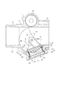
(a)図11に、第一実施形態による弁装置1が備える弁部材20の模式図を示す。図11では、上シャフト25及び下シャフト26が設けられている弁部材20の形状を簡略化し、EGR通路遮断方向側の端部及びEGR通路開放方向側の端部のそれぞれの外形を示している。図11では、弁部材20のEGR通路遮断方向側の端部の外形は、回転軸RA20上の点P25、点P11,点P12,点P13,点P14、及び、回転軸RA20上の点P35で示されている。この場合、弁部材20のEGR通路遮断方向側の端部は、弁部材側シール部21の回転軸RA20に沿う方向の幅が幅Li11であり、回転軸RA20上の点P25,35から縁部225までの距離が距離Ri221となる。一方、弁部材20のEGR通路開放方向側の端部の外形は、回転軸RA20上の点P25、点P21,点P22,点P23,点P14、及び、回転軸RA20上の点P35で示されている。この場合、弁部材20のEGR通路開放方向側の端部は、弁部材側シール部21の回転軸RA20に沿う方向の幅が幅Li12であり、回転軸RA20上の点P25,35から縁部225までの距離が距離Ri222となる。
このように、弁部材20は、弁部材側シール部21の回転軸RA20に沿う方向の幅と、弁部材20の回転軸RA20上の点P25,P35から弁部材20の径方向外側の縁部225,235までの距離との合計がEGR通路遮断方向に向かうにしたがって短くなる。したがって、弁部材20は、EGR通路遮断方向に向かうにしたがって、図11に示す白抜き矢印S21,S22,S23のように外形が小さくなっている。これにより、EGR通路950と弁室110とが遮断されているときに弁部材20と弁ハウジング10との間に弁部材20と弁ハウジング10とを固着する氷が生成されていても、弁部材20は、EGR通路開放方向に回転するとき氷から離れる方向に移動することができるため、弁部材20を確実に回転することができる。したがって、第一実施形態による弁装置1は、吸気通路920とEGR通路950とを確実に連通することができる。
FIG. 11 shows a schematic view of the
As described above, the
(b)弁装置1では、弁部材側シール部21は、EGR通路遮断方向に向かうにしたがって回転軸RA20に沿う方向の長さが短くなるよう形成されている。これにより、弁部材20がEGR通路開放方向に回転するとき、弁部材20は、弁部材20の回転軸RA20に沿う方向のいずれかまたは両方(例えば、図9の領域A22,A23)に付着している氷から離れる方向に移動するため、弁部材20の回転は、氷によって妨げられない。したがって、第一実施形態による弁装置1は、弁部材20の回転軸RA20に沿う方向に付着した氷に影響されることなく弁部材20を確実に回転することができる。
(B) In the valve device 1, the valve member
(c)また、弁装置1では、上アーム22は、EGR通路遮断方向に向かうにしたがって弁部材20の径方向の長さが短くなるよう形成されている。これにより、弁部材20がEGR通路開放方向に回転するとき、弁部材20は、弁部材20の径外方向(例えば、図10の領域A21)に付着している氷から離れる方向に移動するため、弁部材20の回転は、氷によって妨げられない。したがって、第一実施形態による弁装置1は、弁部材20の径外方向に付着した氷に影響されることなく弁部材20を確実に回転することができる。
(C) Further, in the valve device 1, the
(d)式(1)の右辺及び左辺の値は、比較的小さい値となっている。すなわち、弁部材側シール部21に接続する上アーム22の縁部225の弁部材20の回転方向に対する傾きは、比較的小さい傾きとなっている。これにより、弁部材20に付着している氷と弁部材20とはせん断によって付着を解除することができるため、比較的小さい回転トルクによって氷による弁部材20と弁ハウジング10との固着を解除することができる。
(D) The values on the right side and the left side of the equation (1) are relatively small values. That is, the inclination of the
(e)上アーム22の縁部225は、式(1)の関係を満たすよう形成されている。すなわち、弁部材20は、弁部材側シール部21の回転軸RA20に沿う方向の長さが一定の割合で変化するよう形成されている。これにより、弁部材20の形状が比較的簡素になるため、比較的容易に弁部材20を製造することができる。
(E) The
(f)氷が付着するおそれがある外壁面223,233には、撥水性の膜が形成されている。これにより、排気に含まれる水分が付着しにくくなるため、領域A21,A22,A23などに氷ができにくくなる。したがって、氷によって弁部材20と弁ハウジング10とが付着しにくくなるため、弁部材20がEGR通路開放方向に回転するとき、確実に弁部材20を回転することができる。
(F) A water-repellent film is formed on the outer wall surfaces 223 and 233 to which ice may adhere. As a result, the moisture contained in the exhaust is less likely to adhere, so that ice is less likely to form in the regions A21, A22, A23 and the like. Therefore, since the
(第二実施形態)
次に、第二実施形態による弁装置を図12に基づいて説明する。第二実施形態は、弁部材の形状が第一実施形態と異なる。なお、第一実施形態と実質的に同一の部位には同一の符号を付し、説明を省略する。
(Second Embodiment)
Next, the valve device according to the second embodiment will be described with reference to FIG. In the second embodiment, the shape of the valve member is different from that in the first embodiment. The same parts as those in the first embodiment are designated by the same reference numerals, and the description thereof will be omitted.
第二実施形態による弁装置は、弁ハウジング10、弁部材40、上シャフト25、下シャフト26、駆動部35、ギヤ部37などを備える。
The valve device according to the second embodiment includes a
弁部材40は、「弁部材の径方向外側部」としての弁部材側シール部41、上アーム22、及び、下アーム23を有する。弁部材40は、高い耐熱性を有する樹脂材料、例えば、ポリフェニレンスルフィドから形成されている。弁部材40は、弁室110に収容され、弁ハウジング10に対して相対回転可能に設けられている。
The
弁部材側シール部41は、弁部材40の回転軸RA40から見て弁部材40の径方向外側に設けられている。弁部材側シール部41は、ハウジング側シール部材17に当接可能な外壁面411が円筒の径方向外側の壁面の一部と同じ形状となるよう形成されている。外壁面411は、図12に示すように、シール面412、413、及び、接続シール面414,415を有する。シール面412、413、及び、接続シール面414,415が配置される場所及び形状は、第一実施形態のシール面212、213、及び、接続シール面214,215と同じである。
The valve member
第二実施形態では、弁部材側シール部41は、EGR通路遮断方向に向かうにしたがって回転軸RA40に沿う方向の長さが短くなるよう形成されている。
具体的には、弁部材40の側面図である図12に示すように、弁部材側シール部41は、EGR通路遮断方向側に位置する端部416の回転軸RA40に沿う方向の長さLi21がEGR通路開放方向側に位置する端部417の回転軸RA40に沿う方向の長さLi22に比べ短くなっている。また、弁部材側シール部41は、端部416と端部417とのそれぞれから等距離に位置する中間部418の回転軸RA40に沿う方向の長さLi23が、端部416の長さLi21に比べ長く、かつ、端部417の長さLi22に比べ短い。第二実施形態では、長さLi21,Li22,Li23は、以下の関係式(3)が成立する。
Li22−Li23<Li23−Li21 ・・・(3)
弁部材40は、上アーム22の弁部材側シール部41と接続する縁部225及び下アーム23の弁部材側シール部41と接続する縁部235は、図12に示す上面図において曲線状に形成されている。
In the second embodiment, the valve member
Specifically, as shown in FIG. 12, which is a side view of the
Li22-Li23 <Li23-Li21 ... (3)
The
第二実施形態による弁装置では、弁部材側シール部41は、EGR通路遮断方向に向かうにしたがって回転軸RA40に沿う方向の長さが短くなるよう形成されている。これにより、第二実施形態は、第一実施形態の効果(a)〜(c)、(f)を奏する。
In the valve device according to the second embodiment, the valve member
また、第二実施形態による弁装置では、中間部418を挟んで、中間部418からEGR通路遮断方向側に位置する端部416までの回転軸RA40に沿う方向の長さの変化は、中間部418からEGR通路開放方向側に位置する端部417までの回転軸RA40に沿う方向の長さの変化に比べ変化の割合が大きい。これにより、中間部418から端部417までの間はせん断によって氷との付着を解除しつつ、中間部418から端部416までの間は引っ張りによって氷との付着を解除する。このように、中間部418から端部416までの回転軸RA40に沿う方向の長さの変化を比較的大きくすることによって、氷との付着を確実に解除しつつ弁部材40の体格を小さくすることができる。
Further, in the valve device according to the second embodiment, the change in length in the direction along the rotation axis RA40 from the
(第三実施形態)
次に、第三実施形態による弁装置を図13に基づいて説明する。第三実施形態は、弁部材の形状が第一実施形態と異なる。なお、第一実施形態と実質的に同一の部位には同一の符号を付し、説明を省略する。
(Third Embodiment)
Next, the valve device according to the third embodiment will be described with reference to FIG. In the third embodiment, the shape of the valve member is different from that in the first embodiment. The same parts as those in the first embodiment are designated by the same reference numerals, and the description thereof will be omitted.
第三実施形態による弁装置は、弁ハウジング10、弁部材50、上シャフト25、下シャフト26、駆動部35、ギヤ部37などを備える。
The valve device according to the third embodiment includes a
弁部材50は、「弁部材の径方向外側部」としての弁部材側シール部51、上アーム22、及び、下アーム23を有する。弁部材50は、高い耐熱性を有する樹脂材料、例えば、ポリフェニレンスルフィドから形成されている。弁部材50は、弁室110に収容され、弁ハウジング10に対して相対回転可能に設けられている。
The
弁部材側シール部51は、弁部材50の回転軸RA50から見て弁部材50の径方向外側に設けられている。弁部材側シール部51は、ハウジング側シール部材17に当接可能な外壁面511が円筒の径方向外側の壁面の一部と同じ形状となるよう形成されている。外壁面511は、図13に示すように、シール面512、513、及び、接続シール面514,515を有する。シール面512、513、及び、接続シール面514,515が配置される場所及び形状は、第一実施形態のシール面212、213、及び、接続シール面214,215と同じである。
The valve member
第三実施形態では、弁部材側シール部51は、EGR通路遮断方向に向かうにしたがって回転軸RA50に沿う方向の長さが短くなるよう形成されている。
具体的には、弁部材50の側面図である図13に示すように、弁部材側シール部51は、EGR通路遮断方向側に位置する端部516の回転軸RA50に沿う方向の長さLi31がEGR通路開放方向側に位置する端部517の回転軸RA50に沿う方向の長さLi32に比べ短くなっている。また、弁部材側シール部51は、端部516と端部517とのそれぞれから等距離に位置する中間部518の回転軸RA50に沿う方向の長さLi33が、端部516の長さLi31に比べ長く、かつ、端部517の長さLi32に比べ短い。
In the third embodiment, the valve member
Specifically, as shown in FIG. 13 which is a side view of the
弁部材50では、弁部材側シール部51は、回転軸RA50に沿う方向の長さが一定となる部位、例えば、図13に示す領域A51,A52の部位を有する。これにより、弁部材50は、上アーム22の弁部材側シール部51と接続する縁部225及び下アーム23の弁部材側シール部51と接続する縁部235は、図13に示す側面図において階段状に形成されている。
In the
第三実施形態による弁装置では、弁部材側シール部51は、EGR通路遮断方向に向かうにしたがって回転軸RA50に沿う方向の長さが短くなるよう形成されている。これにより、第三実施形態は、第一実施形態の効果(a)〜(c)、(f)を奏する。
In the valve device according to the third embodiment, the valve member
また、第三実施形態による弁装置では、弁部材側シール部51の上アーム22側の縁部52及び下アーム23側の縁部53は、階段状に形成されている。これにより、吸気通路920を流れる吸気を絞るときの絞り特性の自由度を向上することができる。
Further, in the valve device according to the third embodiment, the edge portion 52 on the
(第四実施形態)
次に、第四実施形態による弁装置を図14に基づいて説明する。第四実施形態は、弁部材の形状が第一実施形態と異なる。なお、第一実施形態と実質的に同一の部位には同一の符号を付し、説明を省略する。
(Fourth Embodiment)
Next, the valve device according to the fourth embodiment will be described with reference to FIG. In the fourth embodiment, the shape of the valve member is different from that in the first embodiment. The same parts as those in the first embodiment are designated by the same reference numerals, and the description thereof will be omitted.
第四実施形態による弁装置は、弁ハウジング10、弁部材60、上シャフト25、下シャフト26、駆動部35、ギヤ部37などを備える。
The valve device according to the fourth embodiment includes a
弁部材60は、弁部材側シール部21、上アーム62、及び、下アームを有する。弁部材60は、高い耐熱性を有する樹脂材料、例えば、ポリフェニレンスルフィドから形成されている。弁部材60は、弁室110に収容され、弁ハウジング10に対して相対回転可能に設けられている。
The
上アーム62は、弁部材側シール部21の回転軸に沿う方向の端部のうちセンサカバー112側の端部に設けられている。上アーム62の外壁面には、撥水性の膜が形成されている。上アーム62は、上シャフト25が圧入される通孔624を有する。
The
第四実施形態では、上アーム62及び下アームは、弁部材60の径方向の長さがEGR通路遮断方向に向かうにしたがって短くなるよう形成されている。具体的には、図14に示すように、弁部材60の回転軸上の点P65を設定する。また、上アーム62のうち回転軸RA60に沿う方向において弁部材側シール部21の外壁面211と重なる部位(図14の曲線625)を「弁部材の径方向外側の縁部」としての縁部625とする。
この場合、図14に示すように、上アーム62は、縁部625上の最もEGR通路遮断方向側に位置する点P626と点P65との距離Ri421が、縁部625上の最もEGR通路開放方向側に位置する点P627と点P65との距離Ri422に比べ短くなっている。また、図14に示すように、縁部625上の点であって、点P626となす中心角及び点P627となす中心角が同じ角度α4である点P628と点P65との間の距離Ri423は、距離Ri421に比べ長く、かつ、距離Ri422に比べ短い。第四実施形態では、距離Ri421,Ri422,Ri423は、以下の関係式(4)が成立する。
Ri422−Ri423<Ri423−Ri421 ・・・(4)
すなわち、図14に示すように、縁部625の形状は、第一実施形態の縁部225の形状に比べ、EGR通路遮断方向側の部位が弁部材の回転軸に近い形状となる。
なお、図14には、点P65から距離Ri421と同じ距離にある点の集合である仮想線を仮想線VL40で示している。ここでは、図示されていないが、弁部材60が有する下アームも同様の形状をなしている。
In the fourth embodiment, the
In this case, as shown in FIG. 14, the distance Ri421 between the point P626 and the point P65 located on the
Ri422-Ri423 <Ri423-Ri421 ... (4)
That is, as shown in FIG. 14, the shape of the
In FIG. 14, a virtual line, which is a set of points at the same distance as the distance Ri421 from the point P65, is shown by the
第四実施形態による弁装置では、上アーム62及び下アームは、弁部材60の径方向の長さがEGR通路遮断方向に向かうにしたがって短くなるよう形成されている。これにより、第四実施形態は、第一実施形態の効果(a)〜(c)、(f)を奏する。
In the valve device according to the fourth embodiment, the
また、第四実施形態による弁装置では、上アーム62のEGR通路遮断方向側に位置する部位が、第一実施形態による弁装置1の上アーム22のEGR通路遮断方向側に位置する部位に比べ弁部材の回転軸の近くに位置する。これにより、弁部材60を成形するとき、樹脂の流れがよくなるため、弁部材60の形状を所望の形状とすることができる。
Further, in the valve device according to the fourth embodiment, the portion of the
(第五実施形態)
次に、第五実施形態による弁装置を図15に基づいて説明する。第五実施形態は、弁部材の形状が第一実施形態と異なる。なお、第一実施形態と実質的に同一の部位には同一の符号を付し、説明を省略する。
(Fifth Embodiment)
Next, the valve device according to the fifth embodiment will be described with reference to FIG. In the fifth embodiment, the shape of the valve member is different from that in the first embodiment. The same parts as those in the first embodiment are designated by the same reference numerals, and the description thereof will be omitted.
第五実施形態による弁装置は、弁ハウジング10、弁部材70、上シャフト25、下シャフト26、駆動部35、ギヤ部37などを備える。
The valve device according to the fifth embodiment includes a
弁部材70は、「弁部材の一部」及び「弁部材側当接部」としての弁部材側シール部21、上アーム72、及び、下アームを有する。弁部材70は、高い耐熱性を有する樹脂材料、例えば、ポリフェニレンスルフィドから形成されている。弁部材70は、弁室110に収容され、弁ハウジング10に対して相対回転可能に設けられている。
The
上アーム72は、弁部材側シール部21の回転軸RA70(符号を図示しないが、図9の回転軸RA20等から類推される)に沿う方向の端部のうちセンサカバー112側の端部に設けられている。上アーム72の外壁面には、撥水性の膜が形成されている。上アーム72は、上シャフト25が圧入される通孔724を有する。
The
第五実施形態では、上アーム72及び下アームは、弁部材70の径方向の長さがEGR通路遮断方向に向かうにしたがって短くなるよう形成されている。具体的には、図15に示すように、回転軸RA70上の点P75を設定する。また、上アーム72のうち回転軸RA70に沿う方向において弁部材側シール部21の外壁面211と重なる部位(図15の曲線725)を「弁部材の径方向外側の縁部」としての縁部725とする。
この場合、図15に示すように、上アーム72は、縁部725上の最もEGR通路遮断方向側に位置する点P726と点P75との距離Ri521が、縁部725上の最もEGR通路開放方向側に位置する点P727と点P75との距離Ri522に比べ短くなっている。また、図15に示すように、縁部725上の点であって、点726となす中心角及び点727となす中心角が同じ角度α5である点P728と点P75との間の距離Ri523は、距離Ri521に比べ長く、かつ、距離Ri522に比べ短い。
なお、図15には、点P75から距離Ri521と同じ距離にある点の集合である仮想線を仮想線VL50で示している。ここでは、図示されていないが、弁部材70が有する下アームも同様の形状をなしている。
In the fifth embodiment, the
In this case, as shown in FIG. 15, the distance Ri521 between the point P726 and the point P75 located on the
Incidentally, in FIG. 15 shows a phantom line is a set of points from the point P75 at the same distance as the distance Ri521 in phantom VL 5 0. Although not shown here, the lower arm of the
また、弁部材70では、上アーム72の縁部725は、複数の直線を繋げた形状となっている。すなわち、弁部材70の弁部材側シール部21は、複数の平面を有する。
Further, in the
第五実施形態による弁装置では、上アーム72及び下アームは、弁部材70の径方向の長さがEGR通路遮断方向に向かうにしたがって短くなるよう形成されている。これにより、第五実施形態は、第一実施形態の効果(a)〜(c)、(f)を奏する。
In the valve device according to the fifth embodiment, the
また、第五実施形態による弁装置では、上アーム72の縁部側の縁部725及び下アームの弁部材側シール部側の縁部は、複数の直線を繋げた形状に形成されている。これにより、吸気通路920を流れる吸気を絞るときの絞り特性の自由度を向上することができる。
Further, in the valve device according to the fifth embodiment, the
(第六実施形態)
次に、第六実施形態による弁装置を図16に基づいて説明する。第六実施形態は、弁部材とハウジング側シール部材との位置関係が第一実施形態と異なる。なお、第一実施形態と実質的に同一の部位には同一の符号を付し、説明を省略する。
(Sixth Embodiment)
Next, the valve device according to the sixth embodiment will be described with reference to FIG. The sixth embodiment is different from the first embodiment in the positional relationship between the valve member and the housing side seal member. The same parts as those in the first embodiment are designated by the same reference numerals, and the description thereof will be omitted.
第六実施形態による弁装置6の部分拡大図を図16に示す。図16には、弁部材20とハウジング側シール部材17とが当接した状態の弁装置6の弁部材20及びハウジング側シール部材17との近傍の断面図を示している。図16には、弁装置6における天地方向を示す実線矢印を示している。
A partially enlarged view of the valve device 6 according to the sixth embodiment is shown in FIG. FIG. 16 shows a cross-sectional view of the vicinity of the
弁装置6は、弁部材20とハウジング側シール部材17とが当接しているとき、弁部材20とハウジング側シール部材17とが次のような位置関係となるようEGR管951と吸気管921とが接続されている箇所に設けられている。
すなわち、弁部材20のEGR通路開放方向側の「弁部材の閉弁回転方向とは反対方向側の縁部」としての縁部201は、ハウジング側シール部材17の第一シールリップ部172の「開口の閉弁回転方向とは反対方向側の縁部」としての先端177からみて天方向に位置している。具体的には、先端177を通る仮想水平面VP6より天方向(図16の実線矢印F6側)に位置している。
In the valve device 6, when the
That is, the
弁部材のEGR通路開放方向側の縁部がハウジング側シール部材のEGR通路が有する開口のEGR通路開放方向側の縁部に比べ地方向に位置すると、ハウジング側シール部材の縁部と弁部材との間に氷が形成される。弁部材がEGR通路開放方向に回転するとき、当該氷に回転が妨げられるおそれがある。
第六実施形態による弁装置6では、弁部材20の縁部201は、ハウジング側シール部材17の先端177からみて天方向に位置している。これにより、先端177と弁部材20との間に形成される氷によって弁部材20のEGR通路開放方向への回転は妨げられない。したがって、第六実施形態は、第一実施形態と同じ効果を奏するとともに、弁部材20を確実に回転することができる。
When the edge of the valve member on the EGR passage opening direction side is located in the ground direction with respect to the edge of the opening of the EGR passage of the housing side sealing member on the EGR passage opening direction side, the edge of the housing side sealing member and the valve member Ice is formed between them. When the valve member rotates in the direction of opening the EGR passage, the ice may hinder the rotation.
In the valve device 6 according to the sixth embodiment, the
(他の実施形態)
上述の実施形態では、弁装置は、「流体」として排気の流れを制御するものであるとした。しかしながら、流体は、これに限定されない。
(Other embodiments)
In the above embodiment, the valve device is assumed to control the flow of exhaust gas as a "fluid". However, the fluid is not limited to this.
上述の実施形態では、弁部材は、弁部材側シール部の回転軸に沿う方向の幅、及び、弁部材の回転軸上の点から弁部材の径方向外側の縁部までの距離のそれぞれがEGR通路遮断方向に向かうにしたがって短くなるとした。しかしながら、弁部材側シール部の回転軸に沿う方向の幅または弁部材の回転軸上の点から弁部材の径方向外側の縁部までの距離のいずれか一方がEGR通路遮断方向に向かうにしたがって短くなっており、弁部材側シール部の回転軸に沿う方向の幅または弁部材の回転軸上の点から弁部材の径方向外側の縁部までの距離のいずれか他方は、一定であってもよい。弁部材側シール部の回転軸に沿う方向の幅と弁部材の回転軸上の点から弁部材の径方向外側の縁部までの距離との合計がEGR通路遮断方向に向かうにしたがって短くなればよい。 In the above-described embodiment, the valve member has a width in the direction along the rotation axis of the valve member side seal portion and a distance from a point on the rotation axis of the valve member to the radial outer edge of the valve member. It was assumed that the length became shorter toward the EGR passage blocking direction. However, as either the width of the valve member side seal portion along the rotation axis or the distance from the point on the rotation axis of the valve member to the radial outer edge of the valve member toward the EGR passage blocking direction. It is shortened, and either the width in the direction along the rotation axis of the valve member side seal portion or the distance from the point on the rotation axis of the valve member to the radial outer edge of the valve member, whichever is the other, is constant. May be good. If the sum of the width of the valve member side seal portion in the direction along the rotation axis and the distance from the point on the rotation axis of the valve member to the radial outer edge of the valve member becomes shorter toward the EGR passage blocking direction. good.
上述の実施形態では、弁ハウジングは、三つの通路に連通可能な「流路」を有するとした。しかしながら、「流路」の数はこれに限定されない。「流路」は、二つであってもよく、弁部材の回転によって二つの流路を連通または遮断する弁装置であればよい。 In the above embodiment, the valve housing has a "passageway" that allows communication to the three passageways. However, the number of "channels" is not limited to this. The "flow path" may be two, and may be any valve device that communicates or shuts off the two flow paths by the rotation of the valve member.
第二、三実施形態の弁部材に第四、五実施形態の弁部材の構成を適用してもよい。 The configurations of the valve members of the fourth and fifth embodiments may be applied to the valve members of the second and third embodiments.
第六実施形態における弁部材とハウジング側シール部材との位置関係を、第二〜五実施形態に適用してもよい。 The positional relationship between the valve member and the housing-side seal member in the sixth embodiment may be applied to the second to fifth embodiments.
上述の実施形態では、弁部材の上アーム及び下アームの外壁面には、撥水性の膜が形成されているとした。しかしながら、撥水性の膜はなくてもよい。また、上アーム及び下アームを除く弁部材の部位の外壁面に、撥水性の膜が形成されていてもよい。 In the above-described embodiment, it is assumed that a water-repellent film is formed on the outer wall surfaces of the upper arm and the lower arm of the valve member. However, the water repellent film may not be present. Further, a water-repellent film may be formed on the outer wall surface of the valve member portion excluding the upper arm and the lower arm.
上述の実施形態では、弁部材は円筒状をなしているとした。しかしながら、弁部材の形状はこれに限定されない。球状または球殻状であってもよい。 In the above embodiment, it is assumed that the valve member has a cylindrical shape. However, the shape of the valve member is not limited to this. It may be spherical or spherical shell-shaped.
以上、本発明はこのような実施形態に限定されるものではなく、その要旨を逸脱しない範囲で種々の形態で実施可能である。 As described above, the present invention is not limited to such embodiments, and can be implemented in various embodiments without departing from the gist thereof.
1,6・・・弁装置
10・・・弁ハウジング
20,40,50,60,70・・・弁部材
21,41,51・・・弁部材側シール部(弁部材の径方向外側部)
110・・・弁室(連通空間)
225,235,625,725・・・縁部
Li11,Li12,Li13,Li21,Li22,Li23,Li31,Li32,Li33・・・幅
RA20,RA40,RA50,RA60,RA70・・・回転軸
Ri221,Ri222,Ri223,Ri421,Ri422,Ri423,Ri521,Ri522,Ri523・・・距離
1,6 ...
110 ・ ・ ・ Valve room (communication space)
225, 235,625,725 ... Edges Li11, Li12, Li13, Li21, Li22, Li23, Li31, Li32, Li33 ... Width RA20, RA40, RA50, RA60, RA70 ... Rotating shafts Ri221, Ri222 , Ri223, Ri421, Ri422, Ri423, Ri5211, Ri522, Ri523 ... Distance
Claims (11)
前記弁ハウジングに対して相対回転可能に設けられ、複数の前記流路の一の流路(14)と前記連通空間との間に形成されている前記一の流路の開口の縁部(17)に当接すると当該一の流路と前記連通空間とを遮断する弁部材(20,40,50,60,70)と、
を備え、
前記弁部材が前記開口の縁部から離間した状態から前記開口の縁部に当接している状態となるよう前記弁部材が回転する方向を閉弁回転方向とすると、
前記弁部材の径方向外側部(21,41,51)の少なくとも一部の回転軸(RA20,RA40,RA50)に沿う方向の幅(Li11,Li12,Li13,Li21,Li22,Li23,Li31,Li32,Li33)は、閉弁回転方向に向かうにしたがって狭くなる弁装置。 A valve housing (10) having a plurality of flow paths (12, 13, 14) through which a fluid can flow, and a communication space (110) for communicating the plurality of flow paths.
The edge (17) of the opening of the one flow path, which is provided so as to be rotatable relative to the valve housing and is formed between the one flow path (14) of the plurality of the flow paths and the communication space. ), A valve member (20, 40, 50, 60, 70) that shuts off the one flow path and the communication space, and
With
When the direction in which the valve member rotates so that the valve member is in contact with the edge of the opening from the state of being separated from the edge of the opening is defined as the valve closing rotation direction.
Widths (Li11, Li12, Li13, Li21, Li22, Li23, Li31, Li32) in the direction along at least a part of the rotation axes (RA20, RA40, RA50) of the radial outer portions (21, 41, 51) of the valve member. , Li33) is a valve device that narrows toward the valve closing rotation direction.
前記弁ハウジングに対して相対回転可能に設けられ、複数の前記流路の一の流路(14)と前記連通空間との間に形成されている前記一の流路の開口の縁部(17)に当接すると当該一の流路と前記連通空間とを遮断する弁部材(20,60)と、
を備え、
前記弁部材が前記開口の縁部から離間した状態から前記開口の縁部に当接している状態となるよう前記弁部材が回転する方向を閉弁回転方向とすると、
前記弁部材の径方向外側の縁部(225,235,625)は回転方向において段差なく曲線状に延びており、
前記弁部材の回転軸上の点(P25,P65)から前記弁部材の径方向外側の縁部までの距離(Ri221,Ri222,Ri223,Ri421,Ri422,Ri423)は、閉弁回転方向に向かうにしたがって全範囲で単調減少する弁装置。 A valve housing (10) having a plurality of flow paths (12, 13, 14) through which a fluid can flow, and a communication space (110) for communicating the plurality of flow paths.
The edge (17) of the opening of the one flow path, which is provided so as to be rotatable relative to the valve housing and is formed between the one flow path (14) of the plurality of the flow paths and the communication space. When brought into contact) with the valve member for blocking said first flow path and with said communication space (20,6 0)
With
When the direction in which the valve member rotates so that the valve member is in contact with the edge of the opening from the state of being separated from the edge of the opening is defined as the valve closing rotation direction.
Edge of the radially outer side of the valve member (225,235,62 5) extends in the stepless curved in the direction of rotation,
Distance from the point on the round guinea of said valve member (P25, P6 5) between the edge of the radially outer side of the valve member (Ri221, Ri222, Ri223, Ri421 , Ri422, Ri42 3) is closed rotary the valve device monotonically decreases in the entire range toward the direction.
前記弁部材の前記回転軸上の点(P25)から前記弁部材の径方向外側の縁部までの距離(Ri221,Ri222,Ri223)は、閉弁回転方向に向かうにしたがって一定の割合で短くなる請求項5または6に記載の弁装置。 The radial outer edge (225) of the valve member (20) is formed in a curved shape.
Distance from the point (P25) on the front Symbol rotation axis of the valve member to the edge of the radially outer side of the valve member (Ri221, Ri222, Ri223) is shorter at a constant rate toward the valve closing direction of rotation The valve device according to claim 5 or 6.
前記弁部材の前記回転軸上の点(P65)から前記弁部材の径方向外側の縁部までの距離(Ri421,Ri422,Ri423)は、閉弁回転方向に向かうにしたがって短くなる割合が閉弁回転方向に向かうにしたがって大きくなる請求項5または6に記載の弁装置。 The radial outer edge (625) of the valve member (60) is formed in a curved shape.
Distance from the point (P65) on the front Symbol rotation axis of the valve member to the edge of the radially outer side of the valve member (Ri421, Ri422, Ri423), the proportion to be shorter toward the valve closing direction of rotation is in the closed The valve device according to claim 5 or 6, which increases in the direction of valve rotation.
Priority Applications (3)
| Application Number | Priority Date | Filing Date | Title |
|---|---|---|---|
| JP2017177443A JP6933066B2 (en) | 2017-09-15 | 2017-09-15 | Valve device |
| PCT/JP2018/033728 WO2019054393A1 (en) | 2017-09-15 | 2018-09-12 | Valve device |
| DE112018005161.7T DE112018005161T5 (en) | 2017-09-15 | 2018-09-12 | Valve device |
Applications Claiming Priority (1)
| Application Number | Priority Date | Filing Date | Title |
|---|---|---|---|
| JP2017177443A JP6933066B2 (en) | 2017-09-15 | 2017-09-15 | Valve device |
Publications (3)
| Publication Number | Publication Date |
|---|---|
| JP2019052707A JP2019052707A (en) | 2019-04-04 |
| JP2019052707A5 JP2019052707A5 (en) | 2019-12-19 |
| JP6933066B2 true JP6933066B2 (en) | 2021-09-08 |
Family
ID=65723940
Family Applications (1)
| Application Number | Title | Priority Date | Filing Date |
|---|---|---|---|
| JP2017177443A Active JP6933066B2 (en) | 2017-09-15 | 2017-09-15 | Valve device |
Country Status (3)
| Country | Link |
|---|---|
| JP (1) | JP6933066B2 (en) |
| DE (1) | DE112018005161T5 (en) |
| WO (1) | WO2019054393A1 (en) |
Families Citing this family (2)
| Publication number | Priority date | Publication date | Assignee | Title |
|---|---|---|---|---|
| JP7188403B2 (en) * | 2020-01-31 | 2022-12-13 | 株式会社デンソー | EGR valve device |
| JP7347326B2 (en) | 2020-05-26 | 2023-09-20 | 株式会社デンソー | EGR valve device |
Family Cites Families (6)
| Publication number | Priority date | Publication date | Assignee | Title |
|---|---|---|---|---|
| JPH10220254A (en) * | 1997-02-10 | 1998-08-18 | Denso Corp | Intake device of internal combustion engine |
| JP6009974B2 (en) * | 2013-03-05 | 2016-10-19 | 株式会社デンソー | Fluid control valve |
| KR101866853B1 (en) * | 2015-02-03 | 2018-07-23 | 보르그워너 인코퍼레이티드 | Rotatable switching valve |
| JP6468094B2 (en) | 2015-06-24 | 2019-02-13 | 株式会社デンソー | Low pressure EGR device |
| JP6460012B2 (en) * | 2016-03-03 | 2019-01-30 | 株式会社デンソー | Valve device |
| JP6611339B2 (en) | 2016-03-29 | 2019-11-27 | 有限会社岩本製作所 | Method for producing silicone molded product |
-
2017
- 2017-09-15 JP JP2017177443A patent/JP6933066B2/en active Active
-
2018
- 2018-09-12 DE DE112018005161.7T patent/DE112018005161T5/en not_active Withdrawn
- 2018-09-12 WO PCT/JP2018/033728 patent/WO2019054393A1/en active Application Filing
Also Published As
| Publication number | Publication date |
|---|---|
| JP2019052707A (en) | 2019-04-04 |
| DE112018005161T5 (en) | 2020-06-25 |
| WO2019054393A1 (en) | 2019-03-21 |
Similar Documents
| Publication | Publication Date | Title |
|---|---|---|
| US20190264620A1 (en) | Valve device | |
| US6474318B1 (en) | Air induction system having inlet valve | |
| CN104455672B (en) | Actuator and valve arrangement | |
| CN109416056A (en) | Compressor with compressor with variable entrance | |
| US9574456B2 (en) | Turbocharger | |
| US20090114186A1 (en) | Bypass-intake-flow control apparatus | |
| JP6933066B2 (en) | Valve device | |
| US9109713B2 (en) | Control device and use thereof | |
| US20130309106A1 (en) | Turbocharger | |
| JP5299390B2 (en) | Turbocharger | |
| WO2011108093A1 (en) | Control device for internal combustion engine having supercharger | |
| US20150285132A1 (en) | Actuator rod sealing system | |
| JP5446969B2 (en) | Compressor | |
| US9103235B2 (en) | Valve drive apparatus and supercharger having the same | |
| WO2012176866A1 (en) | Multistage supercharging system | |
| JP6756318B2 (en) | Valve device | |
| JP7342670B2 (en) | valve device | |
| JP7099026B2 (en) | Valve device | |
| US20140165561A1 (en) | Supercharger Turbocharger Bypass Back Draft Inlet Damper for Series Operation | |
| EP2354497A1 (en) | Air delivery device for internal combustion engines | |
| WO2021079721A1 (en) | Resin molded body | |
| JP7409126B2 (en) | valve device | |
| EP2868900B1 (en) | Control system of at least one flap of a fluid duct and fluid duct system | |
| US11125150B2 (en) | Vent insert | |
| KR101788311B1 (en) | Differential Pressure Control Valve For Precise Flow Control |
Legal Events
| Date | Code | Title | Description |
|---|---|---|---|
| A521 | Written amendment |
Free format text: JAPANESE INTERMEDIATE CODE: A523 Effective date: 20191108 |
|
| A621 | Written request for application examination |
Free format text: JAPANESE INTERMEDIATE CODE: A621 Effective date: 20191108 |
|
| A131 | Notification of reasons for refusal |
Free format text: JAPANESE INTERMEDIATE CODE: A131 Effective date: 20200728 |
|
| A521 | Written amendment |
Free format text: JAPANESE INTERMEDIATE CODE: A523 Effective date: 20200908 |
|
| A131 | Notification of reasons for refusal |
Free format text: JAPANESE INTERMEDIATE CODE: A131 Effective date: 20210112 |
|
| A521 | Written amendment |
Free format text: JAPANESE INTERMEDIATE CODE: A523 Effective date: 20210209 |
|
| TRDD | Decision of grant or rejection written | ||
| A01 | Written decision to grant a patent or to grant a registration (utility model) |
Free format text: JAPANESE INTERMEDIATE CODE: A01 Effective date: 20210720 |
|
| A61 | First payment of annual fees (during grant procedure) |
Free format text: JAPANESE INTERMEDIATE CODE: A61 Effective date: 20210802 |
|
| R151 | Written notification of patent or utility model registration |
Ref document number: 6933066 Country of ref document: JP Free format text: JAPANESE INTERMEDIATE CODE: R151 |