KR20160111368A - Method for producing a sprayed cylinder running surface of a cylinder crankcase of an internal combustion engine and such a cylinder crankcase - Google Patents
Method for producing a sprayed cylinder running surface of a cylinder crankcase of an internal combustion engine and such a cylinder crankcase Download PDFInfo
- Publication number
- KR20160111368A KR20160111368A KR1020167015907A KR20167015907A KR20160111368A KR 20160111368 A KR20160111368 A KR 20160111368A KR 1020167015907 A KR1020167015907 A KR 1020167015907A KR 20167015907 A KR20167015907 A KR 20167015907A KR 20160111368 A KR20160111368 A KR 20160111368A
- Authority
- KR
- South Korea
- Prior art keywords
- cylinder
- spraying
- coating
- crankcase
- combustion engine
- Prior art date
- Legal status (The legal status is an assumption and is not a legal conclusion. Google has not performed a legal analysis and makes no representation as to the accuracy of the status listed.)
- Ceased
Links
Images

Classifications
-
- F—MECHANICAL ENGINEERING; LIGHTING; HEATING; WEAPONS; BLASTING
- F02—COMBUSTION ENGINES; HOT-GAS OR COMBUSTION-PRODUCT ENGINE PLANTS
- F02F—CYLINDERS, PISTONS OR CASINGS, FOR COMBUSTION ENGINES; ARRANGEMENTS OF SEALINGS IN COMBUSTION ENGINES
- F02F1/00—Cylinders; Cylinder heads
- F02F1/004—Cylinder liners
-
- C—CHEMISTRY; METALLURGY
- C23—COATING METALLIC MATERIAL; COATING MATERIAL WITH METALLIC MATERIAL; CHEMICAL SURFACE TREATMENT; DIFFUSION TREATMENT OF METALLIC MATERIAL; COATING BY VACUUM EVAPORATION, BY SPUTTERING, BY ION IMPLANTATION OR BY CHEMICAL VAPOUR DEPOSITION, IN GENERAL; INHIBITING CORROSION OF METALLIC MATERIAL OR INCRUSTATION IN GENERAL
- C23C—COATING METALLIC MATERIAL; COATING MATERIAL WITH METALLIC MATERIAL; SURFACE TREATMENT OF METALLIC MATERIAL BY DIFFUSION INTO THE SURFACE, BY CHEMICAL CONVERSION OR SUBSTITUTION; COATING BY VACUUM EVAPORATION, BY SPUTTERING, BY ION IMPLANTATION OR BY CHEMICAL VAPOUR DEPOSITION, IN GENERAL
- C23C4/00—Coating by spraying the coating material in the molten state, e.g. by flame, plasma or electric discharge
- C23C4/04—Coating by spraying the coating material in the molten state, e.g. by flame, plasma or electric discharge characterised by the coating material
- C23C4/06—Metallic material
-
- C—CHEMISTRY; METALLURGY
- C23—COATING METALLIC MATERIAL; COATING MATERIAL WITH METALLIC MATERIAL; CHEMICAL SURFACE TREATMENT; DIFFUSION TREATMENT OF METALLIC MATERIAL; COATING BY VACUUM EVAPORATION, BY SPUTTERING, BY ION IMPLANTATION OR BY CHEMICAL VAPOUR DEPOSITION, IN GENERAL; INHIBITING CORROSION OF METALLIC MATERIAL OR INCRUSTATION IN GENERAL
- C23C—COATING METALLIC MATERIAL; COATING MATERIAL WITH METALLIC MATERIAL; SURFACE TREATMENT OF METALLIC MATERIAL BY DIFFUSION INTO THE SURFACE, BY CHEMICAL CONVERSION OR SUBSTITUTION; COATING BY VACUUM EVAPORATION, BY SPUTTERING, BY ION IMPLANTATION OR BY CHEMICAL VAPOUR DEPOSITION, IN GENERAL
- C23C4/00—Coating by spraying the coating material in the molten state, e.g. by flame, plasma or electric discharge
- C23C4/12—Coating by spraying the coating material in the molten state, e.g. by flame, plasma or electric discharge characterised by the method of spraying
- C23C4/131—Wire arc spraying
-
- C—CHEMISTRY; METALLURGY
- C23—COATING METALLIC MATERIAL; COATING MATERIAL WITH METALLIC MATERIAL; CHEMICAL SURFACE TREATMENT; DIFFUSION TREATMENT OF METALLIC MATERIAL; COATING BY VACUUM EVAPORATION, BY SPUTTERING, BY ION IMPLANTATION OR BY CHEMICAL VAPOUR DEPOSITION, IN GENERAL; INHIBITING CORROSION OF METALLIC MATERIAL OR INCRUSTATION IN GENERAL
- C23C—COATING METALLIC MATERIAL; COATING MATERIAL WITH METALLIC MATERIAL; SURFACE TREATMENT OF METALLIC MATERIAL BY DIFFUSION INTO THE SURFACE, BY CHEMICAL CONVERSION OR SUBSTITUTION; COATING BY VACUUM EVAPORATION, BY SPUTTERING, BY ION IMPLANTATION OR BY CHEMICAL VAPOUR DEPOSITION, IN GENERAL
- C23C4/00—Coating by spraying the coating material in the molten state, e.g. by flame, plasma or electric discharge
- C23C4/12—Coating by spraying the coating material in the molten state, e.g. by flame, plasma or electric discharge characterised by the method of spraying
- C23C4/134—Plasma spraying
-
- F—MECHANICAL ENGINEERING; LIGHTING; HEATING; WEAPONS; BLASTING
- F02—COMBUSTION ENGINES; HOT-GAS OR COMBUSTION-PRODUCT ENGINE PLANTS
- F02F—CYLINDERS, PISTONS OR CASINGS, FOR COMBUSTION ENGINES; ARRANGEMENTS OF SEALINGS IN COMBUSTION ENGINES
- F02F1/00—Cylinders; Cylinder heads
- F02F1/18—Other cylinders
- F02F1/20—Other cylinders characterised by constructional features providing for lubrication
-
- F—MECHANICAL ENGINEERING; LIGHTING; HEATING; WEAPONS; BLASTING
- F02—COMBUSTION ENGINES; HOT-GAS OR COMBUSTION-PRODUCT ENGINE PLANTS
- F02F—CYLINDERS, PISTONS OR CASINGS, FOR COMBUSTION ENGINES; ARRANGEMENTS OF SEALINGS IN COMBUSTION ENGINES
- F02F1/00—Cylinders; Cylinder heads
- F02F2001/008—Stress problems, especially related to thermal stress
Landscapes
- Engineering & Computer Science (AREA)
- Chemical & Material Sciences (AREA)
- Physics & Mathematics (AREA)
- Plasma & Fusion (AREA)
- Mechanical Engineering (AREA)
- Materials Engineering (AREA)
- Chemical Kinetics & Catalysis (AREA)
- Metallurgy (AREA)
- Organic Chemistry (AREA)
- Combustion & Propulsion (AREA)
- General Engineering & Computer Science (AREA)
- Coating By Spraying Or Casting (AREA)
- Cylinder Crankcases Of Internal Combustion Engines (AREA)
Abstract
실린더 크랭크케이스의 실린더 내벽(24)에 용사 방식으로 코팅(30)을 형성하고 이때 불활성 기체를 분무기체로 사용하는 방법들이 공지되어 있다. 그러나, 이런 코팅 층들은 부식되기 쉽다. 이를 방지하기 위해, 용사 과정 동안의 코팅 재료(15)의 이송속도를 8~22.5 kg/h로 할 것을 제안한다. 이 경우, 용사 코팅(30)의 층 공극율이 4.5~25%이고 산화물 함량이 0.5~5%인 실린더 작동면을 갖는 내연기관용 크랭크케이스가 제공된다. Methods are known in which a coating 30 is formed on the cylinder inner wall 24 of the cylinder crankcase in a sprayed manner and an inert gas is used as the atomizer at this time. However, such coating layers are susceptible to corrosion. To prevent this, it is suggested that the transporting speed of the coating material 15 during the spraying process be 8 to 22.5 kg / h. In this case, a crankcase for an internal combustion engine having a cylinder operating surface with a layer porosity of 4.5 to 25% and an oxide content of 0.5 to 5% is provided.
Description
본 발명은 실린더 크랭크케이스의 실린더 내벽에 용사(thermal spraying) 방식으로 코팅을 형성하고 불활성 기체를 분무기체로 사용하는 내연기관의 실린더 크랭크케이스의 용사형 실린더 작동면의 제조방법과, 실린더 내벽의 용사에 의해 이런 방법으로 생산된 실린더 작동면을 갖춘 내연기관용 실린더 크랭크케이스에 관한 것이다. The present invention relates to a method of manufacturing a cylinder-type cylinder operating surface of a cylinder crankcase of an internal combustion engine in which a coating is formed on a cylinder inner wall of a cylinder crankcase by a thermal spraying method and an inert gas is used as an atomizer, To a cylinder crankcase for an internal combustion engine having a cylinder operating surface produced in this way.
실린더 크랭크케이스의 실린더 내벽의 용사에 의해 실린더 작동면 역할을 하는 코팅을 붙이는 다양한 방법이 알려져 있다. 실린더 작동면의 제조를 위해, 특히 플라즈마 분무와 아크 분무가 많이 사용되는데, 아크 분무의 경우 2개의 와이어형 분무재료들 사이에서 아크가 일어나고, 이런 아크에 의해 와이어 팁이 4000℃ 정도의 온도에서 용융되며 준비된 작업물 표면에 분무하게 되고, 버너에서의 플라즈마 분무의 경우, 아노드와 적어도 하나의 캐소드가 좁은 간격만큼 서로 분리되고 직류전압을 걸어주면 그 사이에서 아크가 생긴다. 버너를 통과하는 기체는 아크를 통과하면서 이온돠되어, 온도가 극히 높은 도전 기체가 되어 플라즈마 기체가 되고, 입경 5~120 ㎛ 정도의 분말들을 플라즈마 기체에 분사하면 고열로 인해 용융된다. 플라즈마 기체는 분말 입자들을 품고 있으며 코팅할 실린더 내벽을 향해 코팅재료의 용융 입자들 전부나 일부를 가속한다. Various methods are known for applying a coating that acts as a cylinder operating surface by spraying the inner wall of a cylinder of a cylinder crankcase. Plasma spraying and arc spraying are often used for the production of cylinder operating surfaces, in the case of arc spraying, arcing occurs between two wire type spraying materials, and by such an arc, the wire tip is melted In the case of plasma spraying in the burner, the anode and the at least one cathode are separated from each other by a narrow gap, and an arc is generated between the anode and the cathode when the DC voltage is applied. The gas passing through the burner is ionized while passing through the arc to become a conductive gas having a very high temperature to be a plasma gas. Powders having a particle diameter of about 5 to 120 μm are melted due to the high temperature when sprayed onto the plasma gas. The plasma gas contains the powder particles and accelerates all or a portion of the molten particles of the coating material toward the inner wall of the cylinder to be coated.
DE 697 02 576 T1은 용사에 의해 실린더 내벽을 코팅하는 방법을 소개하는데, 여기서는 먼저 탄소함량이 0.3% 미만인 저탄소강이나 고급강으로 된 용융 분말이나 용융 와이어로 실린더 내벽을 공기를 이용해 스핀코팅하여, 산화물 함량이 높은 하부층을 만든다. 이런 층은 너무 단단하다. 그 결과 다른 층을 입히는데, 이때 불활성 기체를 분무 기체로 사용하여 이 층의 산화물 함량을 크게 줄인다. 이어서, 연한 층을 제거하여 원하는 품질의 표면을 만들되, 단단한 내마모성 하부층을 작동면으로 남겨둔다.DE 697 02 576 T1 discloses a method of coating the inner wall of a cylinder by spraying, wherein the inner wall of the cylinder is first spin-coated with molten powder or molten wire made of low carbon steel or high grade steel having a carbon content of less than 0.3% Create a lower layer with higher oxide content. This layer is too hard. As a result, another layer is applied, in which an inert gas is used as the atomizing gas to greatly reduce the oxide content of this layer. Subsequently, the soft layer is removed to produce the desired quality surface, leaving the hard, wear resistant underlayer as the working surface.
DE 199 34 991 A1에 소개된 플라즈마 분무법에서는, 실린더 작동면의 제조과정중에 질소를 분무기체로 사용한다. 분무기체와 함께 제2의 질소기체를 사용하여 어떤 진공실도 사용하지 않도록 한다. 따라서, 코팅의 산화물 함량을 조절해야만 한다.In the plasma spraying process, as disclosed in DE 199 34 991 A1, nitrogen is used as the atomizer during the production of the cylinder operating surface. Do not use any vacuum chamber with a second nitrogen gas with the atomizer body. Therefore, the oxide content of the coating must be controlled.
그러나, 이런 코팅들의 문제는, 산화물 함량이 높은 층에서는 부식이 아주 빨리 일어나고 산화물 함량이 낮은 층에서는 부식이 좀더 천천히 일어난다는 것이다. 이런 부식 때문에 실린더 작동면의 마모가 커진다. 또, 용사를 하는 기존의 방법은 부식 방지를 위해 고급강이나 적어도 저탄소강을 사용하기 때문에 비용이 아주 많이 든다.However, the problem with these coatings is that corrosion occurs very quickly in layers with high oxide content and corrosion occurs more slowly in layers with low oxide content. This corrosion increases wear on the cylinder operating surface. In addition, the conventional method of spraying is costly because it uses high-grade steel or at least low-carbon steel for corrosion prevention.
본 발명의 목적은 내연기관의 실린더 크랭크케이스의 용사형 실린더 작동면을 제조하는 방법과 이런 실린더 크랭크케이스를 제공하되, 저탄소 합금강을 사용해도 실린더 작동면의 내부식성을 아주 높여 높은 내구성과 저렴한 생산비를 이루는 데 있다.It is an object of the present invention to provide a method of manufacturing a cylinder-type cylinder operating surface of a cylinder crankcase of an internal combustion engine and to provide such a cylinder crankcase with high corrosion resistance of the cylinder operating surface even with low- There is.
본 발명의 이런 목적은 제1항의 특징을 갖는 내연기관의 실린더 크랭크케이스의 실린더 작동면의 제조방법과, 제12항의 특징을 갖는 실린더 크랭크케이스에 의해 달성된다.This object of the invention is achieved by a method for manufacturing a cylinder operating face of a cylinder crankcase of an internal combustion engine having the features of claim 1 and a cylinder crankcase having the features of
용사의 경우 코팅재료의 이송속도가 지금까지 일반적인 4~7 kg/h가 아니라 8~22.5 kg/h이기 때문에 입자속도가 느리되 코팅내 입자 크기는 늘어난다. 따라서, 본 발명에 의하면, 내연기관의 실린더 크랭크케이스에 분무된 코팅층은 공극률이 4.5~25%이고 산화물 함량은 0.5~5%이다. 이런 낮은 산화물 함량은 불활성 기체를 사용해 가능한 것으로, 이때문에 우스타이트 상(wustite phase)도 줄어들어, 층의 산화속도가 크게 줄어들고 부식도 줄어든다. 또, 대형의 개방 공극부가 생겨, 실린더 작동면의 오일보유량이 늘어나, 층 표면의 내부식성도 개선된다. 불활성 기체를 사용해 입자 표면에서의 발열반응이 방지되는데, 탄소함유 코팅재료를 사용할 경우 발열반응 동안 와이어의 탄소가 연소될 수 있다. 따라서, 산화가 줄고 입자온도도 낮아진다.In the case of spraying, the transport speed of the coating material is 8 to 22.5 kg / h instead of the usual 4 to 7 kg / h, so the particle speed is slow and the particle size in the coating is increased. Therefore, according to the present invention, the coating layer sprayed on the cylinder crankcase of the internal combustion engine has a porosity of 4.5 to 25% and an oxide content of 0.5 to 5%. This low oxide content is possible using an inert gas, which in turn reduces the wustite phase, which greatly reduces the rate of oxidation of the layer and reduces corrosion. In addition, a large open air gap is formed, so that the oil retaining amount of the cylinder operating surface is increased, and the corrosion resistance of the layer surface is also improved. An inert gas is used to prevent the exothermic reaction at the surface of the particles, where carbon in the wire can burn during the exothermic reaction when using a carbon containing coating material. Thus, the oxidation is reduced and the particle temperature is lowered.
용사 처리중의 분무기체의 이송속도는 900~1,500 ℓ/min인 것이 좋다. 이런 이송속도에서는 공극율이 높은 내부식성 보호층들을 간단히 형성할 수 있다.The feed rate of the atomizer body during the spraying process is preferably 900 to 1,500 L / min. At these transport speeds, corrosion resistant protective layers with high porosity can be easily formed.
또, 용사 과정 동안의 분무기체의 이송속도가 300~900 ℓ/min이면 더 바람직하다. 이 경우, 노즐에서의 코팅재료의 속도와 온도가 더 감소되어, 코팅재료의 입자에 전달되는 에너지가 줄어든다. 따라서, 질량 이송속도의 증가로 인한 효과가 더 개선되어 공극율이 더 높아진다.It is more preferable that the feeding speed of the atomizer body during the spraying process is 300 to 900 L / min. In this case, the speed and temperature of the coating material at the nozzle are further reduced, reducing the energy delivered to the particles of the coating material. Therefore, the effect due to the increase of the mass transfer rate is further improved, and the porosity becomes higher.
불활성 기체로 질소나 아르곤을 사용한다. 이런 기체를 사용하면 산화물이 적은 층들을 저렴하게 제조할 수 있다. Nitrogen or argon is used as the inert gas. The use of such gases makes it possible to inexpensively produce layers with low oxides.
코팅 재료로 저탄소 합금강을 사용하면 아주 저렴하게 생산할 수 있어서 특히 바람직하다. 이 경우, 조기 산화에 의한 탄소의 조기 연소가 방지되면서도 적절한 내부식성을 얻을 수 있다. 이런 탄소강은 처리가 쉽고, 용사처리를 하는 동안 적절한 경도를 얻는데 필요한 마르텐사이트 조직도 만들 수 있다.The use of a low-carbon alloy steel as a coating material is particularly preferable because it can be produced at a very low cost. In this case, premature burning of carbon due to premature oxidation can be prevented, and adequate corrosion resistance can be obtained. These carbon steels are easy to process and can also make the martensite structure needed to achieve proper hardness during spraying.
코팅은 플라즈마 이행형 와이어아크(PTWA; plasma transferred wire arc) 분무나 회전 싱글와이어(RSW: rotating single wire) 분무를 포함한 플라즈마 분무나 아크 분무로 생성되는 것이 바람직하다. 이 방식은 다공성 저산화물 층을 제조하기에 특히 적합하다.The coating is preferably produced by plasma spraying or arc spraying, including plasma transferred wire arc (PTWA) spraying or rotating single wire (RSW) spraying. This method is particularly suitable for producing a porous low-oxide layer.
이 때, 아르곤-수소 혼합물이나 아르곤-질소 혼합물을 플라즈마 기체로 사용하면, 이 혼합물을 사용할 때 플라즈마 기체의 수소 함량이 5~40 %이기 때문에 바람직하다. 이 방법에 의하면 층의 공극율과 산화물 함량을 원하는대로 얻을 수 있다.At this time, when the argon-hydrogen mixture or the argon-nitrogen mixture is used as the plasma gas, the hydrogen content of the plasma gas is preferably 5 to 40% when the mixture is used. According to this method, the porosity and the oxide content of the layer can be obtained as desired.
또, 입자 표면온도가 1600~2400 ℃이고, 아크 온도는 3000~6000 ℃이며, 플라즈마 기체 온도는 10000~15000 ℃인 것이 좋다. 완전히 용해되지 않은 입자들이 표면에 존재하고, 소량의 산화물이 표면에 존재하게 된다.It is preferable that the particle surface temperature is 1600 to 2400 占 폚, the arc temperature is 3000 to 6000 占 폚, and the plasma gas temperature is 10000 to 15000 占 폚. Particles that are not completely dissolved are present on the surface, and a small amount of oxide is present on the surface.
플라즈마 이송속도는 40~250 ℓ/min인 것이 좋은데, 이 경우 비교적 낮은 입자 온도에서 비교적 낮은 입자 속도를 얻게 된다.The plasma transfer rate is preferably 40 to 250 L / min, which results in relatively low particle velocities at relatively low particle temperatures.
코팅을 연마하여 실린더 작동면으로 만드는 것이 바람직하다. 이 경우, 용사된 층에 추가 공극들이 생기고, 미세한 압력실 역할을 하고 오일을 담을 수 있는 이런 공극들이 노출되여, 기능적인 연마 표면이 형성된다. 또, 축대칭의 일정 두께의 벽을 만들 수 있다. It is desirable to polish the coating to make it the working surface of the cylinder. In this case, additional voids are created in the sprayed layer, such voids that serve as a fine pressure chamber and can contain oil are exposed, forming a functional polishing surface. In addition, it is possible to make a wall having a certain thickness of axisymmetry.
따라서, 실린더 크랭크케이스의 실린더 작동면 제조방법과 이렇게 제조된 실린더 크랭크케이스는 내부식성이 높다. 작동면에 오일이 공급되어, 코팅의 수명이 길어진다. 코팅의 생산비도 종래의 방법과 비교해 줄어드는데, 특히 저탄소 합금강을 사용할 때 더 그렇다. Therefore, the method of manufacturing the cylinder operating surface of the cylinder crankcase and the cylinder crankcase thus manufactured have high corrosion resistance. Oil is supplied to the working surface, and the life of the coating is prolonged. The production cost of coatings is also reduced compared with conventional methods, especially when using low carbon alloy steels.
PTWA 버너나 RSW 버너에 의해 부착된 코팅과 이렇게 제작된실린더 작동면에 대해 첨부 도면을 참조하여 설명한다. The coating attached by the PTWA burner or RSW burner and the cylinder operating surface thus produced will be described with reference to the accompanying drawings.
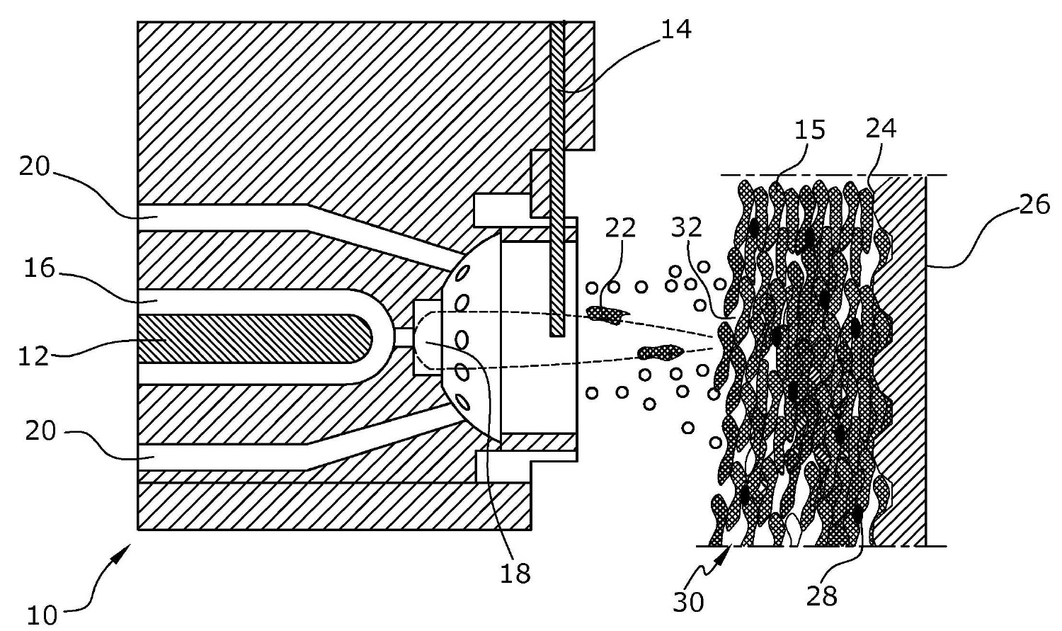
도 1은 PTWA/RSW 버너의 노즐과 실린더 내벽에 형성된 코팅의 구조를 보여주는 단면도.1 is a cross-sectional view showing the structure of a coating formed on a nozzle and a cylinder inner wall of a PTWA / RSW burner;
먼저, 하나 또는 다수의 실린더를 갖춘 크랭크케이스를 알루미늄 주물공정을 통해 종래의 방식으로 주조한다. 실린더 크랭크케이스의 실린더 내벽의 작동면은 내구성이 대부분 내구성이 부적절하여, 언더컷 구조를 만들어 실린더 내벽에 표면을 형성한다. 이어서, 용사 공정으로 실린더 내벽에 코팅을 붙인다. 본 발명에서는 이때 PTWA 또는 RSW 버너(10)를 실린더 안에 삽입하고 축방향으로 회전시키면서 층을 붙인다.First, a crankcase with one or more cylinders is cast in a conventional manner through an aluminum casting process. The working surface of the inner wall of the cylinder of the cylinder crankcase is inadequate in durability for most of the durability, so that an undercut structure is formed to form a surface on the inner wall of the cylinder. Then, the coating is applied to the inner wall of the cylinder by the spraying process. In the present invention, at this time, the PTWA or
도 1에는 버너(10)에 의해 용사층(thermally sprayed layer)이 형성된 실린더 내벽이 도시되어 있다.1 shows an inner wall of a cylinder in which a thermally sprayed layer is formed by a
버너(10)는 제1 전압원에 연결된 제1 전극(12)과, 이 전압원의 반대 극에 연결되고 저탄소 합금강으로 된 제2 전극 역할을 하는 도전 와이어(14)를 포함하며, 도전 와이어는 수직으로 공급되고 코팅재(15) 역할을 한다. 제1 전극(12)은 버너(10)의 보어(16) 안에 배치되고, 보어 안에서 제1 전극(12)을 따라 기체가 소용돌이를 일으키면서 고속으로 노즐(18)을 빠져나간다. 이 기체는 수소 함량이 25% 정도인 아르곤-수소 혼합물로 이루어진다. The
버너(10)를 통과하는 기체는 아크를 통과하면서 이온화된다. 이렇게 해리와 이온화되면서 양이온과 전자로 된 초고온 도전기체인 플라즈마 기체가 생성된다. 이런 플라즈마 기체는 온도가 12,000℃ 정도이고 이송속도는 100ℓ/min 정도이며, 노즐(18)을 통과할 때 노즐의 종축선을 따라서 팽창하여, 노즐(18)에 수직으로 연속 공급되는 와이어(14)에 부딪치면서 전기회로가 닫힌다. 이때 생긴 아크의 온도는 거의 4,000℃이다. 본 발명에 의하면, 와이어는 8~22.5 kg/h의 속도로 공급되고 이곳에 걸린 대량의 전류에 의해 전기저항으로 가열되어, 플라즈마 기체의 충돌에 의해 용융되고 원자화된 상태로 바뀐다. The gas passing through the
보어(16)는 다수의 덕트(20)로 둘러싸이고, 질소와 같은 불활성 기체가 900ℓ/min 정도의 속도로 덕트를 흐른다. 한편, 이런 기체는 불활성 환경을 조성하면서, 와이어(14)의 용융 입자들(22)의 운반기체 역할을 하고 이런 입자들(22)을 분사시킨다. 이 기체류로 인해 실린더(26)의 내벽(24)이 입자(22)로 스핀코팅된다.The
PTWA나 RSW 분무과정을 위해 와이어(14)의 이송속도는 거의 2배로 고속이고 분무 기체는 저속이기 때문에, 스핀코팅 용융물로 실린더 내벽(24)에 부딪치면서 부착되는 코팅재료(15)의 입자(22) 전체가 비교적 저속으로 코팅되는 것은 아니다. 또, 기체류가 저속이고 분무기체로 불활성 기체를 사용하기 때문에 입자 표면온도는 2000℃ 정도로 비교적 낮다. 따라서, 비교적 큰 입자들(22)이 생기고 실린더 내벽(24)에 부착되어, 층의 공극률이 20% 정도로 상당히 높아진다. The
분무기체로 질소를 사용하기 때문에, 코팅재료(15)로 탄소강을 사용함에도 불구하고 입자(22)의 산화를 상당히 줄일 수 있는 불활성 환경이 조성된다. 따라서, 발열반응이 크게 감소되어 대량의 입자들이 생성되기 때문에 입자(22)의 온도가 더 낮아진다. 이때문에 실린더 내벽(24)의 코팅(30)의 산화물(28)의 농도가 대략 3% 정도까지 줄어들어, 우스타이트 상(wustite phase)이 적어 코팅(30)에서의 산화율이 감소되며, 이때문에 부식도 줄어든다. 그러나, 코팅(30)내의 마르텐사이트 조직은 유지되어 코팅의 경도가 적절히 확보된다. Because nitrogen is used as the atomiser, an inert environment is created that can significantly reduce the oxidation of the
그 결과, 원하는 실린더 작동면을 얻기위한 다른 처리공정 동안 코팅(30)이 연마된다. 즉, 표면에서 입자(22)가 제거되면서 오일보유 기능을 갖는 대형 개방 공극들(32)이 생겨, 크랭크케이스의 동작중에 오일을 많이 수집할 수 있고, 이때문에 부식이 더 방지된다. As a result, the
따라서, 이런 용사형 실린더 작동면을 갖는 실린더 크랭크케이스는 내식성이 높은 한편, 아주 높은 윤활성 때문에 마모율도 극히 낮아진다.Therefore, the cylinder crankcase having such a sprayed cylinder operating face is highly corrosion-resistant, while the abrasion rate is also extremely low due to its very high lubricity.
Claims (12)
용사 과정 동안의 코팅 재료(15)의 이송속도가 8~22.5 kg/h인 것을 특징으로 하는 내연기관의 실린더 크랭크케이스의 용사형 실린더 작동면의 제조방법.A manufacturing method of a cylinder-shaped cylinder operating surface of a cylinder crankcase of an internal combustion engine, in which a coating (30) is formed on a cylinder inner wall (24) of a cylinder crankcase by thermal spraying and an inert gas is used as an atomizer :
Characterized in that the conveying speed of the coating material (15) during the spraying process is 8 to 22.5 kg / h.
코팅(30)의 공극율이 4.5~25 %이고 코팅의 산화물 함량이 0.5~5 %인 것을 특징으로 하는 내연기관용 실린더 크랭크케이스.11. A cylinder crankcase for an internal combustion engine having a cylinder operating surface produced by a method according to any one of claims 1 to 11,
Characterized in that the porosity of the coating (30) is between 4.5 and 25% and the oxide content of the coating is between 0.5 and 5%.
Applications Claiming Priority (3)
| Application Number | Priority Date | Filing Date | Title |
|---|---|---|---|
| DE102013112809.2A DE102013112809A1 (en) | 2013-11-20 | 2013-11-20 | A method for producing a sprayed cylinder surface of a cylinder crankcase of an internal combustion engine and such a cylinder crankcase |
| DE102013112809.2 | 2013-11-20 | ||
| PCT/EP2014/067246 WO2015074775A1 (en) | 2013-11-20 | 2014-08-12 | Method for producing a sprayed cylinder running surface of a cylinder crankcase of an internal combustion engine and such a cylinder crankcase |
Publications (1)
| Publication Number | Publication Date |
|---|---|
| KR20160111368A true KR20160111368A (en) | 2016-09-26 |
Family
ID=51301305
Family Applications (1)
| Application Number | Title | Priority Date | Filing Date |
|---|---|---|---|
| KR1020167015907A Ceased KR20160111368A (en) | 2013-11-20 | 2014-08-12 | Method for producing a sprayed cylinder running surface of a cylinder crankcase of an internal combustion engine and such a cylinder crankcase |
Country Status (8)
| Country | Link |
|---|---|
| US (1) | US20160273477A1 (en) |
| EP (1) | EP3071724A1 (en) |
| JP (1) | JP6324508B2 (en) |
| KR (1) | KR20160111368A (en) |
| CN (1) | CN105745350A (en) |
| DE (1) | DE102013112809A1 (en) |
| RU (1) | RU2647064C2 (en) |
| WO (1) | WO2015074775A1 (en) |
Families Citing this family (3)
| Publication number | Priority date | Publication date | Assignee | Title |
|---|---|---|---|---|
| DE102016116815A1 (en) * | 2016-09-08 | 2018-03-08 | Dr. Ing. H.C. F. Porsche Aktiengesellschaft | Process for coating a cylinder of an internal combustion engine and cylinder for an internal combustion engine |
| CN107164715B (en) * | 2017-06-09 | 2019-03-26 | 华晨宝马汽车有限公司 | Method, equipment and product for electric arc line-material coating |
| DE102019112586A1 (en) * | 2019-05-14 | 2020-11-19 | Weldstone Components GmbH | Modified filling chamber for a die casting machine |
Family Cites Families (22)
| Publication number | Priority date | Publication date | Assignee | Title |
|---|---|---|---|---|
| US4663243A (en) * | 1982-10-28 | 1987-05-05 | Union Carbide Corporation | Flame-sprayed ferrous alloy enhanced boiling surface |
| JPS63121648A (en) * | 1986-11-11 | 1988-05-25 | Toyota Motor Corp | Formation of thermally sprayed layer of metal-based composite material |
| JP2576108B2 (en) * | 1987-02-09 | 1997-01-29 | トヨタ自動車株式会社 | Cylinder liner |
| SU1785290A1 (en) * | 1990-10-02 | 1996-06-20 | Институт газа АН УССР | Process of electric arc spraying |
| DK16494A (en) * | 1994-02-08 | 1995-08-09 | Man B & W Diesel Gmbh | Method of producing a cylinder liner as well as such liner |
| US5466906A (en) * | 1994-04-08 | 1995-11-14 | Ford Motor Company | Process for coating automotive engine cylinders |
| DE4427262C1 (en) * | 1994-07-30 | 1995-03-23 | Mtu Muenchen Gmbh | Process and apparatus for flame spraying |
| US5766693A (en) * | 1995-10-06 | 1998-06-16 | Ford Global Technologies, Inc. | Method of depositing composite metal coatings containing low friction oxides |
| US5932293A (en) * | 1996-03-29 | 1999-08-03 | Metalspray U.S.A., Inc. | Thermal spray systems |
| US5958521A (en) | 1996-06-21 | 1999-09-28 | Ford Global Technologies, Inc. | Method of depositing a thermally sprayed coating that is graded between being machinable and being wear resistant |
| US6001426A (en) * | 1996-07-25 | 1999-12-14 | Utron Inc. | High velocity pulsed wire-arc spray |
| JP3460968B2 (en) * | 1998-11-04 | 2003-10-27 | 株式会社豊田中央研究所 | Spray method |
| DE19929247A1 (en) | 1998-12-18 | 2000-06-21 | Volkswagen Ag | Thermal coating of cavity surfaces, especially plasma spray coating of cylinder running surfaces of an i. c. engine crank-case, comprises directing an inert gas stream parallel to the surfaces being coated |
| CH695339A5 (en) * | 2002-02-27 | 2006-04-13 | Sulzer Metco Ag | Cylinder surface layer for internal combustion engines and methods for their preparation. |
| DE10308563B3 (en) * | 2003-02-27 | 2004-08-19 | Federal-Mogul Burscheid Gmbh | Cylinder lining for engines comprises substrate with wear-resistant coating produced by wire-arc spraying which contains martensitic phases and oxygen |
| JP4268491B2 (en) * | 2003-09-30 | 2009-05-27 | 新日本製鐵株式会社 | Conveying roll and hearth roll for continuous annealing furnace |
| JP5168823B2 (en) * | 2006-06-21 | 2013-03-27 | 新日鐵住金株式会社 | Conveying roll and hearth roll for continuous annealing furnace |
| EP2468914B1 (en) * | 2010-12-23 | 2016-09-21 | Linde Aktiengesellschaft | Method and device for arc spraying |
| DE102011085324A1 (en) * | 2011-10-27 | 2013-05-02 | Ford Global Technologies, Llc | Plasma spray process |
| DE102011119087B3 (en) * | 2011-11-22 | 2013-03-14 | Märkisches Werk GmbH | Method for producing a chromium protective layer and its use |
| CN102560326B (en) * | 2012-02-24 | 2014-05-21 | 中国科学院金属研究所 | Thermal spraying device and method for manufacturing quasicrystalline coating |
| JP5586740B2 (en) * | 2013-05-30 | 2014-09-10 | 株式会社ナカシマ | Vitreous thermal spray material for metal substrate roll body, glassy film forming metal substrate roll body, and ozone generator |
-
2013
- 2013-11-20 DE DE102013112809.2A patent/DE102013112809A1/en not_active Withdrawn
-
2014
- 2014-08-12 EP EP14750237.1A patent/EP3071724A1/en not_active Withdrawn
- 2014-08-12 KR KR1020167015907A patent/KR20160111368A/en not_active Ceased
- 2014-08-12 US US15/037,327 patent/US20160273477A1/en not_active Abandoned
- 2014-08-12 JP JP2016533051A patent/JP6324508B2/en active Active
- 2014-08-12 WO PCT/EP2014/067246 patent/WO2015074775A1/en not_active Ceased
- 2014-08-12 RU RU2016123807A patent/RU2647064C2/en active
- 2014-08-12 CN CN201480062972.1A patent/CN105745350A/en active Pending
Also Published As
| Publication number | Publication date |
|---|---|
| RU2647064C2 (en) | 2018-03-13 |
| RU2016123807A (en) | 2017-12-25 |
| CN105745350A (en) | 2016-07-06 |
| DE102013112809A1 (en) | 2015-05-21 |
| JP6324508B2 (en) | 2018-05-23 |
| EP3071724A1 (en) | 2016-09-28 |
| US20160273477A1 (en) | 2016-09-22 |
| WO2015074775A1 (en) | 2015-05-28 |
| JP2016540123A (en) | 2016-12-22 |
Similar Documents
| Publication | Publication Date | Title |
|---|---|---|
| CN105431624B (en) | Method for producing an oxidation protection layer for a piston used in an internal combustion engine and piston having an oxidation protection layer | |
| US5194304A (en) | Thermally spraying metal/solid libricant composites using wire feedstock | |
| JP5689456B2 (en) | Plasma transfer type wire arc spray system, method for starting plasma transfer type wire arc spray system apparatus, and method for coating cylinder bore surface of combustion engine using plasma transfer type wire arc spray system apparatus | |
| Crawmer | Thermal spray processes | |
| JPH07317595A (en) | Covering method of automobile engine cylinder | |
| JP2014530981A (en) | piston | |
| RU2650222C2 (en) | Plasma spraying method | |
| US20140154422A1 (en) | Plasma spraying process | |
| US6004362A (en) | Method for forming an abrasive surface on a tool | |
| US10721813B2 (en) | Arrangement and process for thermal spray coating vehicle components with solid lubricants | |
| KR20160111368A (en) | Method for producing a sprayed cylinder running surface of a cylinder crankcase of an internal combustion engine and such a cylinder crankcase | |
| Steffens et al. | Influence of the spray velocity on arc-sprayed coating structures | |
| CN107904543A (en) | High densification copper alloy coating and preparation method thereof | |
| CN105327804A (en) | Novel supersonic-speed arc spray gun, spraying device and method for preparing Fe-Cr-Ni composite coating | |
| US20150060413A1 (en) | Wire alloy for plasma transferred wire arc coating processes | |
| US6780474B2 (en) | Thermally sprayed chromium nitride coating | |
| RU2366122C1 (en) | Plasmatron for application of coatings | |
| US9611532B2 (en) | Coating additive | |
| CN113454260A (en) | Material composition combination for coating of component of internal combustion engine | |
| US20230056126A1 (en) | Method and system for the metal coating of a bore wall | |
| Arc Sprayed | " HVOF Wire (HIJET) Sprayed Coatings of 0.8% C Steel• Its Structure & Applications | |
| van Rodijnen et al. | Production of particle reinforced graded coatings by wire arc spraying | |
| Tucker | A Brief History of the Development of Thermal Spray Processes and Materials |
Legal Events
| Date | Code | Title | Description |
|---|---|---|---|
| A201 | Request for examination | ||
| PA0105 | International application |
Patent event date: 20160615 Patent event code: PA01051R01D Comment text: International Patent Application |
|
| PA0201 | Request for examination | ||
| PG1501 | Laying open of application | ||
| E902 | Notification of reason for refusal | ||
| PE0902 | Notice of grounds for rejection |
Comment text: Notification of reason for refusal Patent event date: 20170401 Patent event code: PE09021S01D |
|
| E601 | Decision to refuse application | ||
| PE0601 | Decision on rejection of patent |
Patent event date: 20170803 Comment text: Decision to Refuse Application Patent event code: PE06012S01D Patent event date: 20170401 Comment text: Notification of reason for refusal Patent event code: PE06011S01I |