KR20160082591A - Combined scooter and handcart - Google Patents
Combined scooter and handcart Download PDFInfo
- Publication number
- KR20160082591A KR20160082591A KR1020167014953A KR20167014953A KR20160082591A KR 20160082591 A KR20160082591 A KR 20160082591A KR 1020167014953 A KR1020167014953 A KR 1020167014953A KR 20167014953 A KR20167014953 A KR 20167014953A KR 20160082591 A KR20160082591 A KR 20160082591A
- Authority
- KR
- South Korea
- Prior art keywords
- scooter
- combination device
- combined device
- support
- hand cart
- Prior art date
Links
Images


Classifications
-
- B—PERFORMING OPERATIONS; TRANSPORTING
- B62—LAND VEHICLES FOR TRAVELLING OTHERWISE THAN ON RAILS
- B62B—HAND-PROPELLED VEHICLES, e.g. HAND CARTS OR PERAMBULATORS; SLEDGES
- B62B3/00—Hand carts having more than one axis carrying transport wheels; Steering devices therefor; Equipment therefor
- B62B3/02—Hand carts having more than one axis carrying transport wheels; Steering devices therefor; Equipment therefor involving parts being adjustable, collapsible, attachable, detachable or convertible
- B62B3/022—Hand carts having more than one axis carrying transport wheels; Steering devices therefor; Equipment therefor involving parts being adjustable, collapsible, attachable, detachable or convertible folding down the body to the wheel carriage or by retracting projecting parts
-
- B—PERFORMING OPERATIONS; TRANSPORTING
- B62—LAND VEHICLES FOR TRAVELLING OTHERWISE THAN ON RAILS
- B62B—HAND-PROPELLED VEHICLES, e.g. HAND CARTS OR PERAMBULATORS; SLEDGES
- B62B1/00—Hand carts having only one axis carrying one or more transport wheels; Equipment therefor
- B62B1/002—Hand carts having only one axis carrying one or more transport wheels; Equipment therefor convertible from a one-axled vehicle to a two-axled vehicle
-
- B—PERFORMING OPERATIONS; TRANSPORTING
- B62—LAND VEHICLES FOR TRAVELLING OTHERWISE THAN ON RAILS
- B62B—HAND-PROPELLED VEHICLES, e.g. HAND CARTS OR PERAMBULATORS; SLEDGES
- B62B1/00—Hand carts having only one axis carrying one or more transport wheels; Equipment therefor
- B62B1/008—Hand carts having only one axis carrying one or more transport wheels; Equipment therefor having a prop or stand for maintaining position
-
- B—PERFORMING OPERATIONS; TRANSPORTING
- B62—LAND VEHICLES FOR TRAVELLING OTHERWISE THAN ON RAILS
- B62B—HAND-PROPELLED VEHICLES, e.g. HAND CARTS OR PERAMBULATORS; SLEDGES
- B62B1/00—Hand carts having only one axis carrying one or more transport wheels; Equipment therefor
- B62B1/10—Hand carts having only one axis carrying one or more transport wheels; Equipment therefor in which the load is intended to be transferred totally to the wheels
- B62B1/12—Hand carts having only one axis carrying one or more transport wheels; Equipment therefor in which the load is intended to be transferred totally to the wheels involving parts being adjustable, collapsible, attachable, detachable, or convertible
-
- B—PERFORMING OPERATIONS; TRANSPORTING
- B62—LAND VEHICLES FOR TRAVELLING OTHERWISE THAN ON RAILS
- B62K—CYCLES; CYCLE FRAMES; CYCLE STEERING DEVICES; RIDER-OPERATED TERMINAL CONTROLS SPECIALLY ADAPTED FOR CYCLES; CYCLE AXLE SUSPENSIONS; CYCLE SIDE-CARS, FORECARS, OR THE LIKE
- B62K15/00—Collapsible or foldable cycles
- B62K15/006—Collapsible or foldable cycles the frame being foldable
-
- B—PERFORMING OPERATIONS; TRANSPORTING
- B62—LAND VEHICLES FOR TRAVELLING OTHERWISE THAN ON RAILS
- B62K—CYCLES; CYCLE FRAMES; CYCLE STEERING DEVICES; RIDER-OPERATED TERMINAL CONTROLS SPECIALLY ADAPTED FOR CYCLES; CYCLE AXLE SUSPENSIONS; CYCLE SIDE-CARS, FORECARS, OR THE LIKE
- B62K3/00—Bicycles
- B62K3/002—Bicycles without a seat, i.e. the rider operating the vehicle in a standing position, e.g. non-motorized scooters; non-motorized scooters with skis or runners
-
- B—PERFORMING OPERATIONS; TRANSPORTING
- B62—LAND VEHICLES FOR TRAVELLING OTHERWISE THAN ON RAILS
- B62B—HAND-PROPELLED VEHICLES, e.g. HAND CARTS OR PERAMBULATORS; SLEDGES
- B62B2206/00—Adjustable or convertible hand-propelled vehicles or sledges
- B62B2206/006—Convertible hand-propelled vehicles or sledges
Abstract
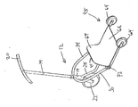
스쿠터 위치와 핸드카트 위치 사이에서 조절을 위한 겸용 장치(10)가 설명된다. 겸용 장치(10)는, 스티어링 조립체(18) 및 적어도 하나의 프론트 휠(22)이 제공되는 전방 부분(12), 및 적어도 하나의 리어 휠(64)이 제공되는 후방 부분(45)을 포함한다. 전방 부분(12)은 공통의 회전 축(A)을 갖는 하나의 피벗 조인트(72) 또는 복수 개의 피벗 조인트들(72)에서 후방 부분(45)에 회전가능하게 연결되어, 스쿠터 위치로부터 핸드카트 위치로의 조절시, 적어도 하나의 리어 휠(64) 및 적어도 하나의 프론트 휠(22)이 서로를 향해서 그리고 서로에 대해 선회된다.A combination device 10 for adjusting between a scooter position and a hand cart position is described. The combination device 10 includes a front portion 12 provided with a steering assembly 18 and at least one front wheel 22 and a rear portion 45 provided with at least one rear wheel 64 . The front portion 12 is rotatably connected to the rear portion 45 at one pivot joint 72 or at a plurality of pivot joints 72 having a common rotational axis A so that the hand portion position At least one rear wheel 64 and at least one front wheel 22 are pivoted toward each other and relative to each other.
Description
본 발명의 장치는, 개인 운송(personal transport)의 도시형 겸용 수단 및 화물 운송(transport for goods) 수단에 관한 것이다. 보다 자세하게는, 본 장치는, 장치가 선택적으로 추진용 모터(motor for propulsion)를 갖는, 스쿠터(scooter)로서 기능하는 스쿠터 위치와 장치가 핸드카트(handcart)로서 기능하는 핸드카트 위치 사이에서 조절가능한 겸용 장치(combined device)에 관한 것이다.The device of the present invention relates to an urban combined means of personal transport and a transport for goods means. More specifically, the device includes a scooter position, the device optionally having a motor for propulsion, the scooter position functioning as a scooter, and the adjustable position between the hand cart position where the device functions as a handcart To a combined device.
걸을 때 또는 놀이에 사용될 때보다 더 빠르게 짧은 거리들을 커버하는 운송 수단으로서 스쿠터들이 사용된다.Scooters are used as a means of transport covering short distances faster than when used for walking or play.
차보다 더 작은 개인 운송의 공지된 수단 모두는, 사용자가 대중 교통 수단(means of public transport) 상에 또는 빌딩들 내로 사용자들을 운송하는 수단을 갖는다면 사용자는 취급하기 쉽지 않다는 문제점을 갖는다. 야외에서(out of door) 이러한 소형 비클(small vehicle)들을 잠금하는 적절하고 안전한(secure) 위치들을 찾는 것이 주요한 문제일 수 있다. 본 발명의 장치는, 스쿠터 또는 핸드카트의 선택된 형태로 하루 내내 사용자와 동반될 수 있다.All of the known means of personal transport smaller than cars have the problem that the user is not easy to handle if the user has the means to transport the users on the means of public transport or into the buildings. Finding appropriate and secure locations to lock these small vehicles out of door can be a major problem. The device of the present invention may be accompanied by a user throughout the day in a selected form of a scooter or hand cart.
예컨대, 사용자가 상점(shop) 안으로 실내에 들어가게 될 때, 스쿠터를 외부에 놓기에 적절한 위치를 찾는 것이 문제가 될 수 있고 시간을 소모할 수 있으며, 추가로, 도난의 위험이 있다. 화물용 트롤리(trolley for goods)를 미는 것과 동시에 상점에서 스쿠터를 가지고 다니는 것은 도전일 수 있다. 따라서, 스토리지 공간을 갖는 스쿠터로서 사용될 수 있고 화물들을 위해 동일한 공간을 갖는 트롤리 또는 핸드카트 내로 쉽게 접혀질 수 있는 장치를 갖는 것이 요망된다.For example, when the user is going to enter the interior of a shop, finding a suitable position to place the scooter outside can be problematic and time consuming and, in addition, there is a risk of theft. Carrying a scooter in a shop while pushing a trolley for goods can be a challenge. It is therefore desirable to have a device that can be used as a scooter with storage space and easily folded into a trolley or hand cart that has the same space for cargoes.
적은 공간을 취하기 위해서 스쿠터가 접혀질 수 있고 그리고/또는 핸들바(handlebar)들의 앞쪽에 여행가방(suitcase) 등을 고정하기 위한 공간을 가질 수 있는 장치들이 공지되어 있다. 이러한 장치들의 일부 예들은, EP 2 514 661 A1, DE 297 15 152 U1, FR 2 818 100, DE 102 04 478 A1 및 DE 31 38 095 A1에서 도시되어 있다. 공지된 스쿠터들의 문제점은, 그 중에서 특히, 이 스쿠터들이 2 개의 또는 그 초과의 조인트들을 가지며, 사용자가 서있는 부분이 핸들바들을 따라 위로 피벗된다(pivoted up)는 점이다. 이는, 짐(luggage)이 핸들바들의 앞쪽에 배치되어야 함을 의미하며, 이는 스쿠터가 흔들릴듯하고(unstable) 휘청거리게(unsteady) 만든다. 많은 조인트(joint)들 및 종종 복잡한 기계적인 부분들(mechanics)에 의해, 파손될 수 있으며 유지보수를 필요로 하는 수개의 컴포넌트들이 또한 존재한다.Apparatuses are known in which the scooter can be folded to take up less space and / or to have space for securing suitcases, etc., in front of handlebars. Some examples of such devices are shown in
일반적으로, 본 발명의 목적은, 따라서 핸드카트 또는 스쿠터로서 야외에서 사용자와 동반할 수 있고, 접혀질 때, 다른 운송 수단에 승차(on board)하는 것이 용이할 수 있어서, 사용자의 도착 위치에서 다시 스쿠터로 펴질(unfolded) 수 있는 개인 운송/화물 운송의 단일 수단을 제조하는 것이다.In general, it is an object of the present invention, therefore, to be able to accompany a user outdoors as a handcart or scooter and to be able to easily board on other transport means when folded, To manufacture a single means of personal transport / freight transport that can be unfolded by a scooter.
본 발명은, 따라서, 스쿠터 위치와 핸드카트 위치 사이에서 쉽게 조절될 수 있는 보다 단순한 설계를 제공하는 목적을 갖는 것이다. The present invention therefore has the object of providing a simpler design that can be easily adjusted between the scooter position and the hand cart position.
또한, 본 발명의 목적은 스쿠터 및 핸드카트 양자 모두로서 양호하게 기능할 수 있는 설계를 제공하는 것이다.It is also an object of the present invention to provide a design that can function well as both a scooter and a hand cart.
이는, 독립항인 제 1 항에서 규정된 바와 같은 겸용 장치에 의해 성취된다. 본 발명의 추가의 실시예들은 종속항인 제 2 항 내지 제 16 항에서 규정된다.This is accomplished by a combination device as defined in the
스쿠터 위치와 핸드카트 위치 사이에서 조절되도록 설계되는 겸용 장치가 제공된다. 겸용 장치는, 스티어링 조립체 및 적어도 하나의 프론트 휠(front wheel)이 제공되는 전방 부분(front part), 및 적어도 2 개의 리어 휠(rear wheel)들이 제공되는 후방 부분(rear part)을 포함한다. 전방 부분은 하나의 피벗 조인트(pivot joint), 선택적으로 복수 개의 피벗 조인트들에서 후방 부분에 회전가능하게 연결되며, 이 피벗 조인트들은 공통의 회전축을 가져, 스쿠터 위치로부터 핸드카트 위치로의 조절시, 리어 휠들 및 적어도 하나의 프론트 휠이 서로를 향해서 그리고 서로에 대해 회전되어, 즉, 리어 휠들이 적어도 하나의 프론트 휠을 향해서 피벗되고 또는 이와 반대로 피벗되거나, 적어도 하나의 프론트 휠 및 리어 휠들 양자 모두가 서로를 향해 피벗되어, 리어 휠들이 핸드카트 위치에서 기저 표면과 접촉되며, 그리고 겸용 장치가 핸드카트 위치에서 리어 휠들에 휠온된다(wheeled on).A combination device designed to be adjusted between the scooter position and the hand cart position is provided. The combination device includes a steering part and a front part where at least one front wheel is provided and a rear part where at least two rear wheels are provided. The front portion is rotatably connected to the rear portion in a pivot joint, optionally a plurality of pivot joints, which pivot joints have a common axis of rotation so that upon adjustment from the scooter position to the hand cart position, The rear wheels and the at least one front wheel are rotated toward each other and relative to each other, i.e., the rear wheels are pivoted toward at least one front wheel, or vice versa, or both at least one front wheel and rear wheels Pivoted toward each other such that the rear wheels are in contact with the base surface at the hand cart position and the combination device is wheeled on the rear wheels at the hand cart position.
핸드카트로서, 이는 열차 또는 버스의 시트 앞쪽에서 플로어에 배치되고, 도착 위치에서, 제품이 펴져서 다시 스쿠터로서 사용되거나 또는 핸드카트로서 함께 당겨질 수 있다. 최종 목적지가 작업장(place of work)이라면, 제품은 데스크 옆에 세워질 수 있다. 이후, 전동 모터가 장비되는 겸용 장치의 변형은, 풋온 차지식(put on charge)일 수 있다.As a hand cart, it is disposed on the floor in front of the seat of a train or bus, and at the arrival position, the product can be spread out and used again as a scooter or as a hand cart. If the final destination is a place of work, the product can be built next to the desk. Then, the variant of the combination device in which the electric motor is equipped may be put on charge.
실용적인 실시예에서, 리어 휠들은, 바람직하게는, 적어도 하나의 프론트 휠을 향해서 그리고 그에 대해서 피벗되어, 리어 휠들이 핸드카트 위치에서 적어도 하나의 프론트 휠 아래에 전체가 또는 부분적으로 놓여진다. 이에 따라, 겸용 장치는, 핸드카트 위치에서 리어 휠들에 휠 온된다. 겸용 장치에는, 바람직하게는 2 개의 리어 휠들 및 하나의 프론트 휠이 제공된다. 이는, 핸드카트 위치에서 겸용 장치를 충분히 안정적으로 만드는 한편, 스쿠터 위치에서 용이하게 스티어링(steer)되게 한다. 실제로, 적어도 하나의 프론트 휠의 회전 축과 리어 휠들의 회전 축은, 이후 서로를 향해서 피벗될 것이고, 핸드카트 위치에서 서로에 사실상 가능한 한 가깝게 놓여질 것이다.In a practical embodiment, the rear wheels are preferably pivoted towards and against the at least one front wheel so that the rear wheels are fully or partially located below the at least one front wheel at the hand cart position. As a result, the combination device is wheeled on the rear wheels at the hand cart position. The combination device is preferably provided with two rear wheels and one front wheel. This makes it easy to steer at the scooter position while making the combination device stable enough at the hand cart position. In practice, the rotational axis of the at least one front wheel and the rotational axis of the rear wheels will then be pivoted towards each other and will be placed as close as practically possible to each other at the hand cart position.
핸드카트 위치에서, 겸용 장치는 바람직하게는 직립 핸드카트 위치(upright handcart position)에서 세워질 수 있으며, 즉, 스티어링 조립체는 실질적으로 수직하거나 수직에 가깝다. 이 위치에서, 겸용 장치는, 휠들 중 하나 또는 그 초과의 휠 상에 그리고, 예컨대 서포트 부분을 갖는 플레이트 수단(plate means)의 도움에 의해, 자립(stand alone)할 수 있다. 서포트 부분은 피벗 조인트에 회전가능하게 연결될 수 있거나 또는 플레이트 수단의 고정된 부분일 수 있다. 스쿠터 위치로부터 핸드카트 위치로의 조절시, 리어 휠들은 스쿠터 위치 및 핸드카트 위치에서 전방 부분의 위치에 대해서 볼 때 적어도 하나의 프론트 휠을 향해서 그리고 이 아래로 피벗될 것이다. In the hand cart position, the combination device can preferably be erected in an upright handcart position, i.e., the steering assembly is substantially vertical or close to vertical. In this position, the combination device can stand alone on one or more of the wheels and with the aid of a plate means, e.g. with a support part. The support portion may be rotatably connected to the pivot joint or may be a fixed portion of the plate means. Upon adjustment from the scooter position to the hand cart position, the rear wheels will pivot toward and below the at least one front wheel as viewed relative to the scooter position and the position of the front portion in the hand cart position.
스티어링 조립체(steering assembly)는, 바람직하게는, 스쿠터 위치에서, 기저 표면(underlying surface)에 대해 직립하는 스티어링 칼럼(steering column)을 포함하며, 기저 표면 상에서, 겸용 장치가 서 있으며, 스티어링 칼럼의 하단부에서 적어도 하나의 프론트 휠에 연결된다. 전방 부분은, 전방 부분에 고정 연결되는 스티어링 가이드(steering guide)를 더 포함할 수 있고, 스티어링 칼럼은 스티어링 가이드를 통해 스티어링 칼럼의 길이 방향 축을 중심으로 스티어링 가이드에 회전가능하게 배열된다.The steering assembly preferably comprises a steering column standing upright relative to the underlying surface at the scooter position and on the base surface a combination device stands and the lower end of the steering column To at least one front wheel. The front portion may further include a steering guide fixedly connected to the front portion, and the steering column is rotatably arranged in the steering guide about the longitudinal axis of the steering column via the steering guide.
피벗 조인트 또는 피벗 조인트들은, 실시예에서, 전방 부분에 고정 연결되는 2 개의 내부 요소들 및 2 개의 외부 요소들을 포함할 수 있으며, 외부 요소들은 외부 요소들 각각의 내부 요소의 대향 측면들 상에 배열되고 후방 부분에 고정되며, 내부 요소들 및/또는 외부 요소들은 피벗 조인트의 회전축을 중심으로 회전가능하다. 내부 요소들 및/또는 외부 요소들은, 바람직하게는 샤프트(shaft) 상에 회전가능하게 배열된다. 샤프트의 회전축은, 이후 피벗 조인트의 회전축에 일치할 것이다. 내부 요소들은 플레이트형 요소들일 수 있다. 외부 요소들은 또한 플레이트형 요소들일 수 있다.The pivot joints or pivot joints may, in an embodiment, comprise two inner elements and two outer elements fixedly connected to the front portion, the outer elements being arranged on opposite sides of the inner elements of each of the outer elements And the inner and / or outer elements are rotatable about an axis of rotation of the pivot joint. The inner and / or outer elements are preferably rotatably arranged on a shaft. The rotational axis of the shaft will then coincide with the rotational axis of the pivot joint. The inner elements may be plate-like elements. The external elements may also be plate-like elements.
내부 요소들은 바람직하게는 돌기(projection)를 포함하고, 외부 요소들은 바람직하게는 대응하는 함몰부(depression)를 포함하여, 이 함몰부 내로 각각의 외부 요소들의 돌기들이 돌출하고, 겸용 장치가 스쿠터 위치와 핸드카트 위치 사이에서 조절될 때 따라서 움직인다(move along). 함몰부의 길이는, 바람직하게는, 돌기들이 각각, 스쿠터 위치 및 핸드카트 위치에서 함몰부의 각각의 단부들에 맞닿아 인접하도록(butt against) 되어 있다. 일 실시예에서, 돌기들은 핀(pin)들의 형태일 수 있는 한편, 함몰부들은 핀들의 형상에 대응하는 형상을 갖는 그루브(groove)들 또는 리세스들의 형태일 수 있다.The inner elements preferably include a projection and the outer elements preferably include corresponding depressions so that the protrusions of the respective outer elements protrude into this depression, And moves along as it is adjusted between the hand cart position. The length of the depression is preferably butt against the respective ends of the depression at the scooter position and the hand cart position, respectively. In one embodiment, the projections may be in the form of pins, while the depressions may be in the form of grooves or recesses having a shape corresponding to the shape of the pins.
피벗 조인트에는, 바람직하게는, 전방 부분 및 후방 부분을 스쿠터 위치와 핸드카트 위치 각각에서 이들 사이의 상대 회전에 대항하여 잠금하는 잠금 기구, 예컨대, 일체형(integrated) 잠금 기구가 제공된다.The pivot joint is preferably provided with a locking mechanism, e.g., an integrated locking mechanism, that preferably locks the front and rear portions against relative rotation between the scooter position and the hand cart position, respectively.
예컨대, 상기 내부 요소들에는 리세스(recess)가 제공되며, 외부 요소들에는 각각의 제 1 리세스들 및 제 2 리세스들이 제공되며, 겸용 장치가 스쿠터 위치에 있을 때, 내부 요소들의 리세스들 및 외부 요소들의 제 1 리세스들이 서로 정렬되는 반면, 겸용 장치가 핸드카트 위치에 있을 때 내부 요소들의 리세스들 및 외부 요소들의 제 2 리세스들이 서로 정렬된다. 피벗 조인트는 잠금 요소 돌기를 갖는 이동가능하게 배열된 잠금 요소를 더 포함하며, 잠금 요소 돌기는 리세스들에 적응되는 형상을 가지며, 전방 부분과 후방 부분을 이들 사이에서의 상대 운동에 대해 잠금하도록 스쿠터 위치와 핸드카트 위치 각각에서 정렬된 리세스들에 배치될 수 있다. For example, the interior elements are provided with a recess, the exterior elements are provided with respective first recesses and second recesses, and when the combination device is in the scooter position, The first recesses of the outer elements and the first recesses of the outer elements are aligned with each other, while the recesses of the inner elements and the second recesses of the outer elements are aligned with each other when the combined apparatus is in the handcart position. The pivot joint further comprises a moveably arranged locking element having locking element protrusions, the locking element protrusion having a shape adapted to the recesses and locking the front portion and the rear portion against relative movement therebetween May be disposed in the recesses aligned in the scooter position and the hand cart position, respectively.
다른 실시예에서, 잠금 기구는 전방 부분에 회전가능하게 배열되는 앵커(anchor)와 같은 형상으로 성형될 수 있으며, 이 앵커는 스쿠터 위치에서 제 1 잠금 요소 및 핸드카트 위치에서 제 2 잠금 요소와 맞물림하도록 적응되며, 제 1 잠금 요소 및 제 2 잠금 요소는 후방 부분 상에 배열된다.In another embodiment, the locking mechanism may be shaped like an anchor rotatably arranged in the front portion, the anchor being engaged with the first locking element at the scooter position and the second locking element at the hand cart position And the first locking element and the second locking element are arranged on the rear portion.
겸용 장치는, 또한 바람직하게는, 후방 부분 및/또는 피벗 조인트 또는 조인트들에 연결되거나 고정되는 플레이트 수단을 포함하여, 사용자가 스쿠터 위치에서 플레이트 수단에 서있을 수 있고, 전체 플레이트 수단 또는 플레이트 수단의 일부가 직립 핸드카트 위치에 있을 때 겸용 장치를 위한 서포트(support)로서 기능한다.The combination device also preferably comprises plate means connected to or fixed to the rear part and / or the pivot joint or joints such that the user may be standing on the plate means at the scooter position and a part of the whole plate means or plate means Serves as a support for the combination device when it is in the upright hand cart position.
일 실시예에서, 플레이트 수단은, 스쿠터 위치에서 사용자가 서있을 수 있는 풋 부분(foot part), 및 풋 부분으로부터 상방으로 돌출하는 서포트 부분(support part)을 포함하여, 이 서포트 부분이 직립 핸드카트 위치에서 서포트로서 기능한다. 플레이트 수단의 풋 부분 및 서포트 부분은 단일편(single piece)으로 구성될 수 있다.In one embodiment, the plate means comprises a foot part which can be user-standable at the scooter position, and a support part projecting upwardly from the foot part, As a support. The foot portion and the support portion of the plate means can be constructed as a single piece.
다른 실시예에서, 플레이트 수단은, 피벗 조인트 또는 피벗 조인트들에 피벗가능하게 연결되는 서포트 부분을 포함하여, 서포트 부분이 직립 핸드카트 위치에서 서포트로서 기능한다. 게다가, 플레이트 수단은 후방 부분에 고정되는 적어도 하나의 별도의 풋 부분을 포함하며, 그 위에서 사용자가 스쿠터 위치에서 서있을 수 있다.In another embodiment, the plate means includes a support portion pivotally connected to the pivot joint or pivot joints such that the support portion serves as a support in the upright hand cart position. In addition, the plate means includes at least one separate foot portion that is secured to the rear portion, above which the user may stand at the scooter position.
플레이트 수단의 다른 실시예에서, 플레이트 수단은 피벗 조인트 또는 피벗 조인트들에 피벗가능하게 연결되는 서포트 부분을 포함하여, 서포트 부분이 직립 핸드카트 위치에서 서포트로서 기능할 수 있으며, 플레이트 수단 전체는 서포트 부분으로 구성되고 사용자가 스쿠터 위치에서 서포트 부분 상에 서있을 수 있도록 적응될 수 있다. In another embodiment of the plate means, the plate means comprises a support portion pivotally connected to the pivot joint or pivot joints such that the support portion can function as a support in the upright hand cart position, And can be adapted to allow the user to stand on the support portion at the scooter position.
대안으로, 플레이트 수단은 서포트 부분 및 바람직하게는 후방 부분에 부착되는 별도의 풋 부분을 포함하며, 서포트 부분은 스쿠터 위치에서 풋 부분에 있는 리세스에 놓일 수 있다. 서포트 부분은, 바람직하게는, 피벗 조인트 또는 피벗 조인트들에 연결되며, 핸드카트 위치로의 조절시, 서포트 부분 및 전방 부분 또는 피벗 조인트 또는 피벗 조인트들 상의 각각의 정지 면들이 서로에 맞닿아 인접하고 서포트 부분의 추가 회전을 방지하는 소정의 지점(certain point)까지, 서포트 부분이 리세스로부터 튀어나온다(flipped out of).Alternatively, the plate means includes a support portion and, preferably, a separate foot portion attached to the rear portion, wherein the support portion can rest on the recess in the foot portion at the scooter position. The support portion is preferably connected to the pivot joint or pivot joints such that upon adjustment to the handcart position the respective stop surfaces on the support portion and the forward portion or on the pivot joints or pivot joints abut against each other The support portion is flipped out of the recess to a certain point that prevents additional rotation of the support portion.
겸용 장치는, 하나, 그러나 바람직하게는 2 개의 기다란 체결 부재들을 포함할 수 있고, 체결 부재는 일단부에서 서포트 부분에 연결되고, 타단부에서 피벗 조인트 또는 각각의 피벗 조인트들에 연결된다. 제 1 체결 부재 단부 부분은, 바람직하게는 제 2 체결 부재 단부 부분에 대해 체결 부재의 길이 방향을 중심으로 90도 회전된다. 체결 부재는, 바람직하게는, 체결 부재 정지 면으로 구성되며, 이 정지 면은, 겸용 장치가 스쿠터 위치로부터 핸드카트 위치로 조절될 때, 체결 부재 정지 면이 체결 부재 정지 요소에 맞닿아 인접하게 되며, 서포트 플레이트의 회전을 제한하도록 적응되며, 이 체결 부재 정지 요소는 겸용 장치의 전방 부분 상에 배열된다.The combination device may include one, but preferably two, elongated fastening members, wherein the fastening member is connected at one end to the support portion and at the other end to the pivot joint or to each of the pivot joints. The first fastening member end portion is preferably rotated 90 degrees about the longitudinal direction of the fastening member with respect to the second fastening member end portion. The fastening member preferably comprises a fastening member stop surface that when the dual purpose device is adjusted from the scooter position to the hand cart position, the fastener member stop face abuttingly engages the fastener member stop element , And is adapted to limit rotation of the support plate, the fastening member stop element being arranged on the front portion of the combination device.
대안으로, 서포트 부분은, 스쿠터 위치로부터 핸드카트 위치로의 회전이 완료되기 이전에 전방 부분 상에서 대응하는 정지 면에 맞닿아 인접하게 되는 정지 면으로 구성되어, 지지 부분은 전방 부분을 향한 후방 부분의 추가 회전이 후속되는 것을 방지하며, 이에 따라 서포트 부분은 직립 핸드카트 위치에서 서포트로서 기능한다.Alternatively, the support portion may consist of a stop surface abutting against the corresponding stop surface on the front portion before the rotation from the scooter position to the hand cart position is completed, and the support portion may comprise a rear portion Thereby preventing further rotation from being followed, whereby the support portion functions as a support in the upright hand cart position.
겸용 장치의 전방 부분에는, 더 바람직하게는, 운송 중 상이한 아이템들의 스토리지를 위한, 스쿠터 위치에서 겸용 장치의 길이 방향에 대해 볼 때, 겸용 장치의 핸들바들 뒤에 스토리지 유닛이 제공된다. 스토리지 유닛은, 유닛에서, 스토리지 유닛에 저장될 수 있고 스티어링 조립체에 체결되고 밖으로 또는 위로 당겨질 수 있도록 적응되는 스토리지 백이 제공되게 구성될 수 있다. 대안으로, 스토리지 유닛은, 사용에 따라 상이한 구성들을 취할 수 있도록 설계될 수 있는데, 예컨대, 겸용 장치에 체결될 때 화물 운송을 위한 백 그리고 스토리지 유닛이 겸용 장치에서 벗겨질 때(taken off) 숄더 백(shoulder bag)일 수 있다.A storage unit is provided behind the handle bars of the combination device, as viewed in the front portion of the combination device, more preferably in the longitudinal direction of the combination device at the scooter position, for storage of the different items during transportation. The storage unit may be configured in the unit to be provided with a storage bag that can be stored in the storage unit and coupled to the steering assembly and adapted to be pulled out or pulled up. Alternatively, the storage unit may be designed to take different configurations depending on usage, for example, a bag for transporting the cargo when it is fastened to the combination device, and a bag for taking off the storage unit from the combination device, or a shoulder bag.
리어 휠들에는, 바람직하게는 겸용 장치의 핸들바들로부터 작동되는 브레이크가 제공될 수 있다.The rear wheels may be provided with brakes which are preferably operated from handle bars of the combination device.
일 실시예에서, 겸용 장치는, 하나의 프론트 휠 및 적어도 2 개의 리어 휠들을 포함하고, 리어 휠들은 공통의 회전축을 갖는다.In one embodiment, the combined device includes one front wheel and at least two rear wheels, the rear wheels having a common rotational axis.
겸용 장치의 핸들바들은, 겸용 장치의 전방 부분 상에 탈착가능하게(detachably) 배열될 수 있다. 또한, 겸용 장치는 바람직하게는 다이렉트 스티어링을 갖는데, 즉 프론트 휠이 스티어링 조립체의 스티어링 칼럼에 직접 체결되어, 스티어링 칼럼이 그의 길이방향 축을 중심으로 회전될 때, 프론트 휠 또는 휠들이 이에 대응하여 또한 회전될 것이라는 것이 언급되어야 한다.The handle bars of the combination device may be arranged detachably on the front portion of the combination device. In addition, the combination device preferably has direct steering, that is, the front wheel is directly fastened to the steering column of the steering assembly such that when the steering column is rotated about its longitudinal axis, Should be mentioned.
본 발명의 상이한 실시예들이 도면들을 참조하여 하기에 설명될 것이다.
도 1 및 도 2는 스토리지 백이 스토리지 콘테이너(storage container)로부터 잡아당겨지는 상태에서 겸용 장치의 제 1 실시예의 사시도들이다.
도 3은 도 2에 도시된 겸용 장치의 측면도이다.
도 4 내지 도 7은 스쿠터 위치 및 핸드카트 위치에서 제 1 발명의 추가의 사시도들이고, 도 6 및 도 7은 스토리지 유닛이 없다.
도 8 내지 도 11은 스쿠터 위치로부터 핸드카트 위치로 겸용 장치의 제 1 실시예의 조절을 예시한다.
도 12는 풋플레이트 및 스토리지 유닛이 없는 겸용 장치의 실시예를 도시한다.
도 13은 겸용 장치의 전방 부품 및 후방 부품을 연결하는 피벗 조인트를 상세히 도시한다.
도 14는 스토리지 백이 스토리지 콘테이너로부터 잡아당겨지는 상태에서 본 발명의 제 2 실시예의 사시도이다.
도 15는 핸드카트 위치에서 본 발명의 제 2 실시예를 도시한다.
도 16은 스쿠터 위치에서 본 발명의 제 2 실시예를 도시한다.
도 17은 핸드카트 위치에서 본 발명의 제 2 실시예의 단면도(아래에서부터 경사지게 봄)이다.
도 18은 스쿠터 위치에서 본 발명의 제 2 실시예의 단면의 측면도이다.
도 19는 스쿠터 위치에서 겸용 장치의 전방 부분 및 후방 부분을 연결하는 피벗 조인트를 도시한다.
도 20은 핸드카트 위치에서 본 발명의 제 2 실시예의 단면의 측면도이다.
도 21은 핸드카트 위치에서 겸용 장치의 전방 부분 및 후방 부분을 연결하는 피벗 조인트를 도시한다.
도 22는 스쿠터 위치에서 겸용 장치의 전방 부분 및 후방 부분을 연결하는 피벗 조인트를 도시한다.
도 23은 핸드카트 위치에서 겸용 장치의 전방 부분 및 후방 부분을 연결하는 피벗 조인트를 도시한다.
도 24 내지 도 27은 스쿠터 위치로부터 핸드카트 위치로 겸용 장치의 제 2 실시예의 조절을 예시한다.
도 28은 스쿠터 위치에서 상대 운동에 대해서 전방 부분 및 후방 부분을 잠금하기 위한 잠금 기구를 도시한다.
도 29는 도 28에 표시된 바와 같이 피벗 조인트 둘레의 영역의 단면을 도시한다.
도 30은 핸드카트 위치에서 상대 운동에 대해서 전방 부분 및 후방 부분을 잠금하기 위해 도 28 및 도 29에 도시된 바와 같은 잠금 기구를 도시한다.
도 31은 도 30에 표시된 바와 같이 피벗 조인트 주위 영역의 단면을 도시한다.
도 32는 겸용 장치의 핸들 바들로부터 작동되는 리어 휠들 상에 브레이크 장치(brake device)가 제공되는 겸용 장치를 도시한다.
도 33은 스쿠터 위치에서 본 발명의 제 3 실시예의 사시도이다.
도 34는 스쿠터 위치에서 본 발명의 제 3 실시예의 측면도이다.
도 35는 핸드카트 위치에서 본 발명의 제 3 실시예의 측면도이다.
도 36은 스쿠터 위치에서 본 발명의 제 3 실시예의 사시도(본질적으로, 뒤에서부터 봄)이다.
도 37은 스쿠터 위치에서 본 발명의 제 3 실시예의 사시도(본질적으로, 앞에서부터 봄)이다.
도 38a 내지 도 38c는, 스토리지 유닛의 크기/볼륨이 사용되는 방법에 관해서 조절될 수 있도록 스토리지 유닛이 구성되는 상태로, 본 발명의 제 3 실시예를 도시한다.
도 39a 및 도 39b는 플레이트 수단이 별개의 풋 부분 및 서포트 플레이트를 포함하는 겸용 장치의 2 개의 실시예들을 도시한다.Different embodiments of the present invention will be described below with reference to the drawings.
Figs. 1 and 2 are perspective views of a first embodiment of a combination device in a state in which a storage bag is pulled from a storage container. Fig.
3 is a side view of the combined apparatus shown in Fig.
Figures 4-7 are further perspective views of the first invention at scooter and hand cart locations, and Figures 6 and 7 do not have storage units.
Figs. 8-11 illustrate the adjustment of the first embodiment of the combined device from the scooter position to the hand cart position.
Figure 12 shows an embodiment of a combined apparatus without a foot plate and a storage unit.
Fig. 13 shows in detail a pivot joint connecting the front part and the rear part of the combination device.
14 is a perspective view of a second embodiment of the present invention in a state in which the storage bag is pulled out from the storage container;
Fig. 15 shows a second embodiment of the present invention at a hand cart position.
Figure 16 shows a second embodiment of the invention at a scooter position.
Fig. 17 is a cross-sectional view of the second embodiment of the present invention at a hand cart position (oblique spring from below).
18 is a side view of a cross section of a second embodiment of the present invention at a scooter position;
19 shows a pivot joint connecting the front portion and the rear portion of the combination device at the scooter position.
20 is a side view of a cross section of a second embodiment of the present invention at a hand cart position;
Fig. 21 shows a pivot joint connecting the front portion and the rear portion of the combination device at the hand cart position.
Figure 22 shows a pivot joint connecting the front portion and the rear portion of the combination device at the scooter position.
Fig. 23 shows a pivot joint connecting the front portion and the rear portion of the combination device at the hand cart position.
Figs. 24-27 illustrate the adjustment of the second embodiment of the combined device from the scooter position to the hand cart position.
28 shows a locking mechanism for locking the front portion and the rear portion relative to the relative movement at the scooter position.
29 shows a cross section of a region around the pivot joint as shown in Fig.
Fig. 30 shows a locking mechanism as shown in Figs. 28 and 29 for locking the front portion and the rear portion relative to the relative movement at the hand cart position.
31 shows a cross section of the area around the pivot joint as shown in Fig.
32 shows a combination device in which a brake device is provided on the rear wheels operated from the handle bars of the combination device.
33 is a perspective view of a third embodiment of the present invention at a scooter position.
34 is a side view of a third embodiment of the present invention at a scooter position;
35 is a side view of a third embodiment of the present invention in a hand cart position;
Fig. 36 is a perspective view of the third embodiment of the present invention at the scooter position (essentially, from the back). Fig.
37 is a perspective view (essentially, from the front) of a third embodiment of the present invention at a scooter position;
Figures 38A-C illustrate a third embodiment of the present invention in which the storage unit is configured to be adjustable as to how the size / volume of the storage unit is used.
Figures 39A and 39B show two embodiments of a combination device in which the plate means comprises a separate foot portion and a support plate.
본 발명의 3 개의 실시예들이 하기에서, 도 1 내지 도 13에 도시된 바와 같은 제 1 실시예, 도 14 내지 도 27에 도시된 바와 같은 제 2 실시예 및 도 33 내지 도 38에 도시된 바와 같은 제 3 실시예로 설명될 것이다. 3 개의 실시예들은, 스쿠터 위치와 핸드카트 위치 사이에서 겸용 장치를 조절하기 위한 동일한 해법에 기초하지만, 약간 상이한 상세 해법들을 갖는다. Three embodiments of the present invention will now be described in detail in a first embodiment as shown in Figs. 1 to 13, a second embodiment as shown in Figs. 14 to 27, and a second embodiment as shown in Figs. 33 to 38 Will be described as the third embodiment. The three embodiments are based on the same solution for adjusting the combination device between the scooter position and the hand cart position, but have slightly different detailed solutions.
도 1 내지 도 13은 겸용 장치(10)의 제 1 실시예를 예시한다. 겸용 장치(10)는 2 개의 피벗 조인트들(72)에 회전 가능하게 연결되는 전방 부분(12) 및 후방 부분(45)을 포함한다. 2 개의 피벗 조인트들(72)은 도 8 내지 도 12에 표시된 바와 같이 공통 회전축(A)을 갖는다. 축(A)을 중심으로 전방 부분(12)에 대해 후방 부분(45)을 회전시킴으로써, 겸용 장치(10)는, 사용자가 스쿠터로서 겸용 장치(10)를 채용할 수 있는 스쿠터 위치로부터, 사용자가 핸드카트 또는 트롤리로서, 예컨대, 상점에서 겸용 장치(10)를 채용할 수 있는 핸드카트 위치로 조절될 수 있다. 겸용 장치(10)의 스쿠터 위치와 핸드카트 위치 사이의 차이는, 도 4 및 도 5에서 명확하게 보일 수 있다.Figs. 1 to 13 illustrate a first embodiment of the
전방 부분(12)은, 스티어링 가이드(14)를 포함하는 프레임으로 구성되며, 스티어링 가이드(14)는 그의 하단부에서 프론트 휠 포크(23)에 연결된다. 프론트 휠(22)은 프론트 휠 포크(23)에 장착된다. 프론트 휠 포크(23)는, 원통형 구멍을 갖도록 바람직하게 구성되는 스티어링 가이드(14)에 고정되며, 이 구멍에서 겸용 장치의 스티어링 조립체(18)가 배열될 수 있다. 스티어링 조립체(18)는, 스티어링 가이드(14)에 회전가능하게 그리고 바람직하게는 제거가능하게 배열된다. 이는, 겸용 장치(10)의 스토리지를 용이하게 할 것이다. 대안으로, 스티어링 조립체(18)는, 물론, 스티어링 가이드(14)가 전방 부분(12)으로부터 분해될 수 없도록 스티어링 가이드(14)에 영구적으로 체결될 수 있다. The
스티어링 조립체(18)는 스티어링 칼럼(19)(스티어링 칼럼(19)은 스티어링 가이드를 통해서 스티어링 칼럼의 길이방향 축을 중심으로 스티어링 가이드(14)에서 회전가능하게 배열되고) 및 스쿠터로서 사용될 때, 겸용 장치(10)를 스티어링하기 위해서 사용자가 채용하는 스티어링 핸들(20)을 포함한다. 도시된 바와 같이, 스티어링 핸들은, 스티어링 칼럼(19)의 길이 방향 축에 대해 횡단하게 배열된다. 스티어링 조립체(18)는, 프론트 휠 포크(23)에 직접 또는 간접적으로 연결되며, 이에 따라 스쿠터로서 채용될 때에 사용하는 동안, 사용자가 겸용 장치(10)를 스티어링 하는 것을 가능하게 한다.The steering
전방 부분(12)은, 제 1 전방 부분 사이드 바(30) 및 제 2 전방 부분 사이드 바(34)를 더 포함하며, 이들은 일단부에서 예컨대, 용접에 의해 스티어링 가이드(14)에 연결된다. 제 1 전방 부분 사이드 바(30) 및 제 2 전방 부분 사이드 바(34)의 대향 단부들 각각은, 전방 부분(12) 및 후방 부분(45)을 연결하는 피벗 조인트(72)의 일부를 형성한다. 전방 부분 횡단 바(transverse bar)(38)는, 제 1 전방 부분 사이드 바(side bar)(30)와 제 2 전방 부분 사이드 바(34) 사이를 연장하고, 이들에 체결되며, 그리고 이들의 단부들에 근접한 전방 부분 사이드 바들(30, 34)에, 예컨대 용접에 의해 체결되어, 전방 부분 사이드 바들(30, 34)의 단부들이 도면들에 도시된 바와 같이 피벗 조인트들(72)의 일부로서 구성될 수 있다. 전방 부분(12)은, 전방 부분 중앙 바(central bar)(25)를 더 포함하며, 이 바는 제 1 전방 부분 사이드 바(30)와 제 2 전방 부분 사이드 바(34) 사이에 배열되고, 일단부에서 스티어링 가이드(14)와 타단부에서 전방 부분 횡단 바(38) 사이를 연장하고, 이들에 체결된다.The
전방 부분 중앙 바(25)는, 바람직하게는, 스티어링 가이드(14) 상에서 제 1 전방 부분 사이드 바(30)와 제 2 전방 부분 사이드 바(34)보다 하부에 체결된다. 게다가, 전방 부분 중앙 바(25)에는, 바람직하게는 도면들에서 도시되는 바와 같이 벤드(bend)(28)가 제공되어, 전방 부분 중앙 바(25)의 일부가 벤드(28)와 전방 부분 횡단 바(38) 사이에서 본질적으로 수평하게 놓인다. 게다가, 제 1 전방 부분 사이드 바(30) 및 제 2 전방 부분 사이드 바(34)(스쿠터 위치에서 사이드로부터 봄)는, 바람직하게는, 이들이 서로에 대해 동일한 높이(level with)에 놓이도록 배열된다(예컨대, 도 8 내지 도 11 참조). 전방 부분(12)의 이러한 구성은, 스토리지 유닛(41)이 전방 부분(12) 상에 배열될 수 있고, 스토리지 유닛(41)이 전방 부분 중앙 바(25) 상에 놓여질 수 있지만, 전방 부분 사이드 바들(30, 34)이 횡단(lateral) 방향 및 전방 방향으로 스토리지 유닛(41)에 대한 지지를 제공한다는 것을 의미한다.The front portion
스토리지 유닛에는, 예컨대, 도 1에 도시된 바와 같이 위로 피벗될 수 있는 덮개(lid)(42)가 제공될 수 있다. 겸용 장치(10)가 스쿠터로서 사용되고, 그리고 겸용 장치(10)가 핸드카트로서 사용되는, 양자 모두의 경우에, 스토리지 유닛(41)이 상이한 물품(different article)들의 수송을 위해서 사용될 수 있다.The storage unit may be provided, for example, with a
이러한 스토리지 유닛(41)에서의 공간(예컨대, 도 4 참조)은, 일부의 사람들에게는 상당히 제한될 수도 있다. 이에 따라, 스토리지 유닛(41)에서 스토리지 백(43)을 배열하는 것에 대한 대안이 있다. 스토리지 백(43)이 사용 중이 아닐 때, 이 백은 스토리지 유닛(41)에 보관된다. 사용자가 스토리지 백(43)을 채용하기를 원하는 경우, 이 백은 스토리지 유닛(41)으로부터 잡아당겨지며, 스티어링 조립체(18)에, 예컨대, 스티어링 핸들(20)에 적절한 패스너(fastener)들에 의해서 체결된다. 패스너들은, 예컨대, 코드(cord) 또는 테이프를 포함할 수 있다. 스토리지 백(43)은, 바람직하게는 상부가 개방된다. 대안으로 또는 추가로, 스토리지 백(43)에는 사이드에 하나 또는 그 초과의 개구들이 제공될 수 있다. 이들 개구들은, 바람직하게는, 예컨대, 집 패스너(zip fastener), 후크 앤 루프 패스너(hook-and-loop fastener)들 등을 사용하여 개방 및 폐쇄될 수 있다. 사람이 예컨대 쇼핑하러 나갈 예정일 때, 겸용 장치(10)는 이에 따라 상점에서 스쿠터로서, 상점에서 스토리지 백(43)에 화물이 놓여지는 핸드카트로서, 그리고 스토리지 백의 화물들을 가지고 상점으로부터 집으로 오는 도중에는 스쿠터 또는 핸드카트로서 사용될 수 있다. 스토리지 백(43)이 사용중이 아닐 때, 이 백은 스토리지 유닛(41) 내로 쉽게 넣어질 수 있다.The space in this storage unit 41 (see, for example, FIG. 4) may be considerably limited for some people. Accordingly, there is an alternative to arranging the
겸용 장치(10)의 후방 부분(45)은, 제 1 후방 부분 사이드 바(47) 및 제 2 후방 부분 사이드 바(51), 및 앞쪽 후방(forward rear) 부분 횡단 바(55)(제 1 후방 부분 사이드 바(47) 및 제 2 후방 부분 사이드 바(51)에 각각의 단부들이 체결됨) 및 뒤쪽 후방 부분(rearward rear) 횡단 바(59)(제 1 후방 부분 사이드 바(47) 및 제 2 후방 부분 사이드 바(51)에 각각의 단부들이 체결됨)를 포함한다. The
최후방(겸용 장치의 길이 방향에서 봄)에서, 제 1 후방 부분 사이드 바(47) 및 제 2 후방 부분 사이드 바(51)에는 휠 포크(63)가 제공된다. 리어 휠(64)은 휠 포크들(63)에 배열된다.In the rear end (spring in the longitudinal direction of the combined device), the first rear
앞쪽 단부(겸용 장치의 길이 방향에서 봄)에서, 제 1 후방 부분 사이드 바(47) 및 제 2 후방 부분 사이드 바(51)는 각각의 피벗 조인트들(72)의 일부를 형성한다. 피벗 조인트들(72)은, 도 12 및 도 32에서 표시된 바와 같이 동일한 회전축(A)을 갖는다.In the front end (spring in the longitudinal direction of the combination device), the first rear
피벗 조인트들(72) 중 하나가 도 13에 상세하게 도시된다. 도 13이 예시하는 바와 같이, 제 2 전방 부분 사이드 바(34) 및 제 2 후방 부분 사이드 바(51)는, 전방 부분 사이드 바(34) 및 후방 부분 사이드 바(51)에서 홀들을 통해 지나가는 볼트(73)에 의해 연결된다.One of the pivot joints 72 is shown in detail in FIG. 13, the second front
도 13에 표시된 바와 같이, 볼트(73)에는 너트를 위한 스레드들이 제공될 수 있다. 따라서, 겸용 장치의 전방 부분(12) 및 후방 부분(45)은, 예컨대, 도 12에서 표시된 바와 같이 볼트(73)를 통해 축(A)을 중심으로 서로에 대해서 회전될 수 있다.As shown in Fig. 13,
피벗 조인트(72)는, 바람직하게는, 핸드카트 위치로부터 스쿠터 위치로의 조절 중, 겸용 장치가 스쿠터 위치 내로 이동함에 따라, 전방 부분(12)과 후방 부분(45) 사이에서의 추가적인 상대 회전이 방지되도록 구성된다. 이는, 후방 부분 사이드 바들(47, 51)에 후방 부분 정지 면(81)이 각기 제공되는 것으로 성취된다. 후방 부분 정지 면(81)은, 바람직하게는 주름식(corrugated)이다. 각각의 후방 부분 정지 면들(81)과 협동하는 하나 또는 그 초과의 후방 부품 정지 요소들(82)이 전방 부분(12) 상에 배열되어, 겸용 장치(10)가 스쿠터 위치에 있는 것으로 자체적으로 알게 됨에 따라, 후방 부분 정지 면들(81)은 이들의 각각의 후방 부분 정지 면들(82)에 대항하여 접촉하게 된다. 도 13에 표시된 바와 같이, 후방 부분 정지 요소(82)는 코루게이션 골(corrugation valley)에 진입하고, 이에 따라 전방 부분(12)과 후방 부분(45) 사이에서 시도되는 추가의 상대 회전에 대해 코루게이션 마루(corrugation crest)에 맞닿아 인접한다. 이에 따라, 겸용 장치가 스쿠터 위치에 있고 사용자가 후방 부분(45) 상에 서있을 때, 전방 부분(12)과 후방 부분(45) 사이에서 추가의 상대 회전이 방지된다.The pivot joint 72 preferably has an additional relative rotation between the
후방 부분 정지 요소들(82)은, 전방 부분 사이드 바들(30, 34) 상에 배열된 별개의 볼트 등일 수 있다. 그러나, 후방 부분 정지 요소들(82)은 바람직하게는, 전방 부분 횡단 바(38)로 구성된다. 또한, 물론, 전방 부분 사이드 바들(30, 34) 상에 정지 면들 그리고 제 2 후방 부분 사이드 바(51) 상에 정지 요소를 배열할 가능성이 있음이 이해되어야 한다.The rear
후방 부분(45)은, 또한, 후방 부분 사이드 바들(47, 51)과 후방 부분 횡단 바들(55, 59)에 의해 형성된 프레임 상에 배열되는 플레이트 수단(66)을 포함한다. 플레이트 수단(66)은, 적절한 방식으로, 예컨대, 스크류들에 의해 후방 부분 사이드 바들(47, 51) 및/또는 후방 부분 횡단 바들(55, 59)에 체결될 수 있다.The
플레이트 수단(66)은, 겸용 장치가 스쿠터로서 사용될 때 사람이 플레이트 수단(66) 상에 서있을 수 있도록 적응되고, 그리고 플레이트 수단(66)은 스티어링 장치(18)가 실질적으로 수직한 직립(upright) 위치에서 안정된 채 유지되도록 겸용 장치가 핸드카트로서 사용될 때 겸용 장치(10)를 위한 서포트로서 작용한다.The plate means 66 are adapted to allow the person to stand on the plate means 66 when the combination device is used as a scooter and the plate means 66 are adapted to allow the person to be standing on the plate means 66, Serves as a support for the
본 발명의 제 1 실시예에서, 플레이트 수단(66)은 풋 부분(68) 및 서포트 부분(69)으로 구성된다. 풋 부분(68) 및 서포트 부분(69)은 서로 각지게(at an angle) 배열되어, 겸용 장치가 직립 핸드카트 위치에 있을 때 겸용 장치(10)를 위한 서포트로서 기능하는데, 즉 사용자는 예컨대 도 11에 도시된 바와 같이 직립 위치에 겸용 장치(10)를 둘 수 있고, 겸용 장치가 쓰러지지 않고(falling over) 장치를 놓을 수 있다(let go of). 직립 위치에서, 스티어링 조립체(18)는, 바람직하게는, 수직하거나 실질적으로 수직한 위치에서 상방으로 돌출한다.In a first embodiment of the invention, the plate means 66 consists of a
풋 부분과 서포트 부분 사이에서 정확한 각도가 각각의 개별적인 경우에서 판정되어야 할 것이지만, 0도 내지 90도의 임의의 각도일 수 있다. 바람직하게는, 각도는 90도에 근접하고, 어떠한 경우라도, 0도 보다 90도에 근접한다. 풋 부분(68)과 서포트 부분(69) 사이 각도의 크기(magnitude)는, 또한 서포트 부분(69)의 길이와 관련되는 것을 알 수 있을 것이며, 길이 및 각도는, 겸용 장치(10)가 서포트 부분(69)의 도움에 의해 직립 핸드카트 위치에서 안정을 유지하도록 서로 조절될 수 있을 것이다. 서포트 부분(69)의 길이는, 핸드카트 위치에서 기저(underlying) 표면에 대해서 놓이는 서포트 부분(69)의 상부 에지(70)와 풋 부분(68)과 서포트 부분(69) 사이의 연결부(junction) 사이의 거리로서 여기서 이해되어야 한다.The exact angle between the foot portion and the support portion should be determined in each individual case, but may be any angle between 0 and 90 degrees. Preferably, the angle is close to 90 degrees and, in any case, approaches 90 degrees from 0 degrees. It will be appreciated that the magnitude of the angle between the
도 8 내지 도 11은, 도 8에 도시된 바와 같은 스쿠터 위치로부터 도 11에 도시된 바와 같은 핸드카트 위치로의 겸용 장치(10)의 조절을 도시하는 4 개의 도면들이다. 도 9에서, 스티어링 조립체는, 하방 및 전방으로 피벗되고 있으며, 피벗 조인트들(72)을 이동시키고, 회전 축(A)이 상방으로 이동되었으며, 전방 부분(12)이 후방 부분(45)에 대해 회전된다. 도 10에서, 리어 휠들(64)이 프론트 휠 위로 피벗되고 있으며, 서포트 부분(69)은 기저 표면(99)을 향해서 가리키기 시작하고 있다. 도 11에서, 스티어링 조립체(18)는 실질적으로 수직 위치로 다시 직각이 되고 있다. 이제, 후방 부분(45)이 전방 부분(12) 아래에 놓이는 반면, 지지 부분(69)의 상부 에지(70)는 기저 표면(99)에 대해서 놓여지며, 겸용 장치(10)는 직립 핸드카트 위치에서 단독으로 안정적으로 세워지는 것을 보장한다. 8 to 11 are four views showing the adjustment of the
도 11에서 볼 수 있는 바와 같이, 전방 부분(12) 및 후방 부분(45)은, 핸드카트 위치에서 기저 표면(99)과 접촉하게 되는 것이 단지 리어 휠들(64)만이도록 배열된다. 겸용 장치(10)에 2 개의 리어 휠들 및 단지 하나의 프론트 휠이 제공되기 때문에, 겸용 장치(10)가 핸드카트로 사용될 때, 보다 양호한 안정성을 부여할 것이다. 프론트 휠들 및 리어 휠들의 상이한 개수들의 분배에 의해, 디바이스가 핸드카트로서 사용될 때, 충분한 안정성을 제공할 수 있는 2 이상의 프론트 휠들이 존재하고, 프론트 휠들이 기저 표면과 접촉하게 되는 반면, 리어 휠 또는 휠들이 핸드카트 위치에서 프론트 휠들 위에 배열될 것이다.11, the
본 발명의 제 2 실시예는 도 14 내지 도 27에 도시된다. 이미 언급된 바와 같이, 플레이트 수단(66)을 제외하고, 프론트 부분(12) 및 리어 부분(45)은, 이 실시예 및 전술된 실시예에서 동일하다. 2 개의 실시예들과 동일한 피처들은, 따라서 하기에서 다시 설명되지 않을 것이다. 이는, 특히, 스티어링 가이드(14), 프론트 휠 포크(23) 및 프론트 휠(22), 핸들바(18), 전방 부분 사이드 바들(30, 34), 전방 부분 횡단 바(38), 전방 부분 중앙 바(25), 후방 부분 사이드 바들(47, 51), 후방 부분 횡단 바들(55, 59), 리어 휠 포크들(63) 및 리어 휠들(64)을 갖는 전방 부분(12) 및 후방 부분(45)의 구조에 적용한다. 본 발명의 제 2 실시예에서 플레이트 수단(66) 및 플레이트 수단이 스쿠터 위치와 핸드카트 위치 사이의 조절 상에서 기능하는 방법이 도 17 내지 도 23에 명확하게 도시된다.A second embodiment of the present invention is shown in Figs. 14 to 27. Fig. As already mentioned, with the exception of the plate means 66, the
플레이트 수단(66)은, 서포트 부분(68)을 포함하며, 이 서포트 부분은 겸용 장치(10)가 스쿠터로서 사용될 때 사용자가 그 위에 서있으며, 겸용 장치(10)가 핸드카트로서 사용될 때, 전술된 발명의 제 1 실시예에서 서포트 부분(69)과 동일한 방식으로 기능한다. 서포트 부분(68)은 체결 부재들(76)에 의해 2 개의 피벗 조인트들(72)에 피벗식으로 체결된다. 체결 부재들(76)은, 바람직하게는, 기다란 플레이트 요소들로서 구성되며, 이 요소들은 일단부에서 스크류들 또는 다른 적절한 패스너들에 의해 서포트 부분(68)에 체결되고, 타단부에서 제각기 피벗 조인트들(72)에 피벗식으로 배열된다. 서포트 부분(68)은, 이에 따라 전방 부분(12) 및 후방 부분(45)과 동일한 축(A)을 중심으로 회전할 수 있다.The plate means 66 includes a
도면에 표시된 바와 같이, 체결 부재들(76)의 일단부는, 타단부에 대해 체결 부재들의 길이 방향 축을 중심으로 90도 회전되어, 이에 따라 제각기 서포트 부분(68) 및 피벗 조인트(72)에 대한 부착을 용이하게 한다.As shown in the figure, one end of the
전방 부분 사이드 바들(30, 34) 및 후방 부분 사이드 바들(47, 51)과 마찬가지로, 체결 부재들(76)에는, 각기 피벗 조인트(72)의 커넥팅 볼트들(73)이 통과되는 구멍들이 제공된다. 이에 따라, 서포트 부분(68)은 전방 부분(12) 및 후방 부분(45)의 나머지 양자 모두에 대해 피벗 조인트(72)에 피벗식으로 지지된다. Similar to the front partial side bars 30 and 34 and the rear partial side bars 47 and 51, the
체결 부재들(76)에는, 바람직하게는, 체결 부재 정지 면(84)이 제공된다(도 19, 도 21 및 도 22 참조). 체결 부재 정지 면(84)은, 체결 부재 정지 요소(85)에 맞닿아 인접하게 되고 전방 부분(12)에 대해 서포트 부분(68)의 추가 회전을 방지하도록 구성되며, 서포트(68)가 본 발명의 제 1 실시예에서 서포트 부분(69)과 동일한 방식으로 핸드카트 위치에서 겸용 장치(10)에 대한 서포트로서 기능하는 소망하는 위치로 서포트(68)가 회전한다. 체결 부재 정지 요소(85)는, 전방 부분(12) 상에 배열되고, 유리하게는, 전방 부분 횡단 바(38)로 구성될 수 있다. 본 발명의 실제 실시예에서, 전방 부분 횡단 바(38)는 후방 부분 정지 요소(82) 및 체결 부재 정지 요소(85) 양자 모두로서 기능할 수 있다. 대안으로, 체결 부재 정지 요소(85)는, 전방 부분 사이드 바들(30, 34)에 체결되는 2 개의 별개의 볼트들 등일 수 있다.The
겸용 장치(10)가 직립 핸드카트 위치에 있을 때, 기저 표면에 대해서 놓여질 서포트 에지(71)와 함께 서포트(68)가 구성된다. 서포트 에지(71)는, 바람직하게는, 겸용 장치(10)가 스쿠터 위치에 있을 때 겸용 장치(10)의 길이 방향에 대해 볼 때 서포트(68)의 후방 에지이다.When the
도 24 내지 도 27은, 도 24에 도시된 바와 같이 스쿠터 위치로부터 도 27에 도시된 바와 같이 핸드카트 위치로 겸용 장치(10)의 제 2 실시예가 조절되는 법을 도시하는 일련의 도면들이다.Figs. 24-27 are a series of diagrams showing how the second embodiment of the combined
도 8 내지 도 11에 도시된, 본 발명의 제 1 실시예의 조절에서와 같이 동일한 방식으로, 스티어링 조립체(18)가 전방 및 하방으로 피벗된다(도 25 참조). 이는, 조인트(72)가 리프팅되고, 프론트 휠(22) 및 리어 휠들(64)이 서로를 향해 이동하는 것을 유발한다. 먼저, 플레이트 수단(66)은, 도 25에 도시된 바와 같이 전방 부분(12)에 대해 후방 부분(45)과 함께 회전할 것이지만, 체결 부재 정지 면(84)이 체결 부재 정지 요소(85)와 맞닿게 되며, 체결 부재 정지 요소는, 도면들에 도시된 실시예에서 전방 부분 횡단 바(38)로 구성되고, 전방 부분(12)에 대해 플레이트 수단(66)의 추가 회전이 도 26에 표시된 바와 같이 방지된다. 겸용 장치(10)의 조절이 완료되었을 때, 플레이트 수단(66)을 제외하고, 후방 부분(45)이 전방 부분(12) 아래에 놓이며, 스티어링 조립체(18)는 다소(more or less) 수직한 위치로 다시 위로 피벗되었다. 플레이트 수단(66)의 서포트 에지(71)는, 기저 표면에 대해서 놓여질 것이며, 겸용 장치가 도 27에 도시된 바와 같이 직립 위치에 안정적으로 유지되는 것을 보장할 것이다. 도면들에서 도시된 겸용 장치에는 2 개의 리어 휠들(64) 및 하나의 프론트 휠(22)이 제공되기 때문에, 본 발명의 제1 실시예의 경우에서와 같이, 리어 휠들(64)은, 핸드카트 위치에서 기저 표면과 접촉하는 한편, 프론트 휠(22)은 표면으로부터 리프트 업된다. In the same manner as in the adjustment of the first embodiment of the present invention shown in Figures 8-11, the steering
도 28 내지 도 31은, 스쿠터 위치 및 핸드카트 위치의 전방 부분(12)과 후방 부분(45) 사이에서 상대 회전에 대항하여 겸용 장치를 잠금하기 위해서 설명된 실시예들 양자 모두에서 함께 사용될 수 있는 배열체를 도시한다.Figs. 28-31 illustrate an alternative embodiment of the present invention, which can be used together in both of the embodiments described for locking the combination device against relative rotation between the
도 28은 스쿠터 위치에서 본 발명에 따른 겸용 장치(10)를 도시한다. 도 29는 도 28의 피벗 조인트(72) 둘레 영역을 도시한다. 도 28 및 도 29에 도시된 바와 같이, 겸용 장치(10)에는 전방 부분(12) 및 후방 부분(45)을 스쿠터 위치와 핸드카트 위치에서 이들 사이의 상대 회전에 대항하여 잠금하는 잠금 기구(87)가 제공된다. 잠금 기구(87)는 전방 부분(12)에 회전가능하게 고정되는 앵커(88)를 포함한다. 앵커는, 후방 부분(45) 상에 제공되는 잠금 볼트들과 맞물림하는 후크들(89)을 포함한다. 도 28 및 도 29에서, 전방 부분(12) 및 후방 부분(45)을 스쿠터 위치에서 이들 사이의 상대 회전에 대항하여 잠금하기 위해서, 앵커(89)가 후방 부분(45) 상에 잠금 볼트(도시 생략)와 맞물림하도록 어떻게 적응될 수 있는지를 나타낸다. 도 30 및 도 31은, 전방 부분(12) 및 후방 부분(45)을 핸드카트 위치에서 이들 사이의 상대 회전에 대항하여 잠금하기 위해서, 앵커가 제 2 잠금 볼트(90)와 맞물림하도록 어떻게 피벗되는지를 도시한다.Fig. 28 shows a combined
도 32에서, 겸용 장치(10)는 플레이트 수단(66) 없이 도시된다. 겸용 장치(10)에는 리어 휠들(64) 상에 브레이크(92)가 제공된다. 휠들(64) 중 단지 하나에만 브레이크가 제공되는 것이 가능할 수 있지만, 바람직하게는, 양쪽 휠들에 브레이크(92)가 제공된다. 브레이크(92)는, 바람직하게는 스티어링 조립체(18)의 스티어링 핸들(20) 상에 배열되는 브레이크 레버(94)에 의해 작동된다. 브레이크 레버(94)는, 바람직하게는, 도 32에 표시된 바와 같이, 하나 또는 그 초과의 와이어들(93)에 의해서 브레이크 또는 브레이크들(92)에 연결된다.In Fig. 32, the
리어 휠들(64) 상의 브레이크들(92)은 적어도 2 개의 목적들을 갖는다. 첫 번째로, 이 브레이크들은, 겸용 장치(10)가 스쿠터로서 사용될 때 속도를 감소시키커나 또는 겸용 장치(10)가 핸드카트로서 사용될 때 급격한 다운힐(downhill) 상에서, 슬로프들을 감소시키도록 사용될 것이다. 게다가, 브레이크는 스쿠터 위치와 핸드카트 위치 사이에서 겸용 장치(10)를 조절하는 것을 용이하게 할 것이다. 리어 휠들(64)이 브레이크들(92)에 의해 잠금된다면, 겸용 장치(10)가 핸드카트 위치를 취할 때까지, 스티어링 조립체(18)는 아래로 용이하게 피벗될 수 있고 프론트 휠(22)은 리어 휠들(64)을 향해서 용이하게 푸시될 수 있다. 또한, 핸드카트 위치로부터 스쿠터 위치로의 조절은, 프론트 휠은, 겸용 장치(10)가 스쿠터 위치를 취할 때까지 리어 휠들(64)에서 용이하게 끌어내어질(pulled away from) 수 있도록, 리어 휠들(64)이 브레이크들(92)에 의해서 잠금될 수 있을 때 사용자에게 용이해질 것이다. The
도면들에서, 겸용 장치(10)에는 하나의 프론트 휠 및 2 개의 리어 휠들이 제공된 채 도시된다. 이는, 동작(manoeuvrability) 및 안정성(stability)에 관하여 최적의 해법을 제공하도록 고려된다. 그러나, 예컨대, 2 개의 프론트 휠들 및 2 개의 리어 휠들의 사용을 방지하기 위한 것은 아무 것도 존재하지 않는다. 2 개 초과의 프론트 휠들 및/또는 리어 휠들이 또한 요망된다면 사용될 수 있다.In the figures, the combined
도면들에서 도시된 본 발명의 2 개의 실시예들에 2 개의 피벗 조인트들이 제공되지만, 물론, 전방 부분 및 후방 부분이 도 33 내지 도 38의 실시예들에서 도시된 바와 같이, 단일 피벗 조인트에 의해서 또는 선택적으로 모든 피벗 조인트들이 공통의 회전축을 갖는 한, 2 개 초과의 피벗 조인트들에 의해서 연결되도록 이 부분들이 구성되는 것을 방지하는 것은 아무 것도 존재하지 않는다.Although two pivot joints are provided in the two embodiments of the present invention shown in the figures, it should be understood that the front and rear portions are of course formed by a single pivot joint, as shown in the embodiments of Figs. 33-38 Or alternatively, there is nothing to prevent these parts from being configured to be connected by more than two pivot joints, as long as all of the pivot joints have a common axis of rotation.
도 33 내지 도 38은 겸용 장치(10)의 제 3 실시예를 도시한다. 이 실시예는 단지 하나의 피벗 조인트(72)와 함께 구성되며, 그리고 전방 부분(12) 및 후방 부분(45)에 있어서 약간 단순해진 설계를 갖는다. 도면들에 도시된 바와 같이, 전방 부분(12)은 예컨대, 용접에 의해서 스티어링 가이드(14)에 고정식으로 연결되는 전방 부분 바(24)를 포함한다. 전방 부분 바(24)의 타단부는 피벗 조인트(72)에 체결된다. 이는, 하기 도 36 및 도 37의 설명과 관련하여 보다 상세히 설명될 것이다.33 to 38 illustrate a third embodiment of the
스티어링 조립체(18)는, 스티어링 칼럼(19)에 대해 상기 설명된 바와 동일한 방식으로 구성될 수 있는데, 이 스티어링 칼럼(19)은 스티어링 가이드(14)에 회전가능하게 배열되고 그의 하단부에서 프론트 휠 포크(23) 및 그의 상단부에서 스티어링 핸들에 연결된다. 사용자가 스티어링 핸들(20)을 잡고 핸들을 돌릴 때, 이에 따라 프론트 휠(22)이 대응하여 회전될 것이다.The steering
후방 부분(45)은, 제 1 후방 부분 사이드 바(47) 및 제 2 후방 부분 사이드 바(51)를 포함하며, 이들 양자 모두는 일단부에서 피벗 조인트(72)에 연결된다. 이는, 또한 도 36 및 도 37의 설명과 관련되어 보다 상세히 설명될 것이다. 후방 부분 사이드 바들(47, 51)의 타단부에는 도면들에서 도시된 바와 같이 리어 휠들(64)을 유지하는 리어 휠 포크들(63)이 배열된다. 후방 부분(45)에는, 후방 부분에 더 큰 안정성을 부여하기 위해서 후방 부분 횡단 바(54)가 더 제공될 수 있다. 후방 부분(45)의 상부에 도 38a 및 도 38c에 도시된 바와 같이 풋 부분의 형태로 플레이트 수단이 배열되며, 이 플레이트 수단은 플레이트를 후방 부분에 고정하기 위한 다른 적절한 방법들 또는 체결 스크류들에 의해서 후방 부분(45)에 고정될 수 있다. 플레이트 수단에는, 사용자가 장치를 잡지않고 장치가 안정적으로 유지되도록 핸드카트 위치에서 안정적인 위치를 겸용 장치(10)에 부여할 수 있는 풋플레이트에 대한 길이 및 각도와 함께, 또한, 도 1 내지 도 11에 도시된 바와 동일한 방식으로 직립 에지가 제공될 수 있다. The
피벗 조인트(72)는 도 36 및 도 37에 도시된 바와 같이 구성될 수 있다. 도 36에서, 2 개의 내부 요소들(98)이 도시되어 있으며, 이 내부 요소들(98)은 도시된 바와 같이 전방 부분(24)의 각각의 사이드 상에서 하나의 내부 요소가 전방 부분(24)의 단부 부분에 체결된다. 내부 요소들은, 예컨대, 전방 부분(24)에 용접될 수 있다. 내부 요소들(98)은 샤프트(100) 상에 배열되고, 샤프트(100) 주위에서 원형 경로(circular path)로 연장하는 함몰부(depression)(102)와 함께 구성된다. 함몰부들은, 예컨대, 그루브(groove)들 또는 리세스(recess)들일 수 있다.The pivot joint 72 may be configured as shown in Figs. 36 and 37. Fig. In Figure 36, two
피벗 조인트(72)는, 2 개의 외부 요소들(99)을 더 포함하는데, 2 개의 외부 요소들(99)은 이들의 2 개의 내부 요소들(98) 중 각각 하나의 외부측 상에 배열된다. 2 개의 외부 요소들(99)은 또한, 내부 요소들(98) 및 외부 요소들(99)이 샤프트(100)를 통해 축을 중심으로 서로에 대해서 회전될 수 있도록 샤프트(100) 상에 배열된다. 2 개의 외부 요소들(99) 중 하나는, 예컨대, 용접에 의해서 제 1 후방 부분 사이드 바(47)에 체결되는 한편, 다른 외부 요소(99)는 예컨대, 용접에 의해서 제 2 후방 부분 사이드 바(51)에 체결된다. 내부 요소들(98) 및 외부 요소들(99)이 서로에 대해 회전함에 따라, 이들 요소들은, 바람직하게는, 도면들에서 표시된 바와 같이, 원형 구성 및 동일한 직경을 갖는다.The pivot joint 72 further includes two
외부 요소들 중 하나 이상, 그러나 바람직하게는 양자의 외부 요소들(99)에는 내부 요소(98)들의 각각의 함몰부들(102) 내로 돌출하는 돌기(101)가 제공된다. 돌기는, 예컨대, 핀(pin) 또는 유사한 요소일 수 있다. 도 36에 도시된 바와 같이, 돌기(101)는, 겸용 장치가 스쿠터 위치에 있을 때 함몰부(102)의 일단부에 충돌하며(butt against), 사용자가 풋플레이트에 서 있을 때(도시 생략) 전방 부분(12)과 후방 부분(45) 사이에서 상대 회전을 추가로 방지한다. 도 34 및 도 35에 표시되는 바와 같이, 돌기들(101)은, 도 34에 도시된 바와 같은 스쿠터 위치로부터 도 35에 도시된 바와 같은 핸드카트 위치로의 조절 중 함몰부들(102)을 따를 것이다. 핸드카트 위치에서, 돌기(101)는 스쿠터 위치와 비교하여 함몰부(102)의 대향 단부에 맞닿아 인접하며, 이에 따라 전방 부분(12)과 후방 부분(45) 사이에서 상대 회전을 추가로 방지한다. 따라서, 함몰부(102)의 길이는, 전방 부분과 후방 부분 사이의 상대 회전이 얼마나 많이 가능한지의 여부를 판정한다.One or more but preferably both
스쿠터 위치 및 핸드카트 위치에서 전방 부분(12)과 후방 부분(45) 사이 상대 이동에 대하여 겸용 장치(10)를 잠금하기 위해서, 피벗 조인트(72)에는, 도 36 및 도 37에서 가장 명확하게 도시되어 있는 잠금 기구(96)가 제공될 수 있다. 잠금 기구(96)는, 2 개의 내부 요소들(98) 사이에 놓이며 일단부에서 2 개의 내부 요소들(98)에 회전가능하게 체결되는 잠금 요소(locking element)(108)를 포함한다. 잠금 요소(108)의 대향 단부에서, 요소에는 하나 이상의 잠금 요소 돌기가 제공되지만, 바람직하게는 외부 요소들(99)을 향해서 밖으로 돌출하는 2 개의 잠금 요소 돌기들(109)이 제공된다. 게다가, 내부 요소들은, 내부 요소들의 외부 에지(반경 방향으로 봄)에서 리세스들(104)과 함께 구성되며, 이 리세스들(104)은 잠금 요소 돌기들(109)이 끼워맞춰지는(fit) 형상을 갖는다. 외부 요소들(99)은, 외부 요소들의 외부 에지들(반경 방향으로 봄)에서 각각의 제 1 리세스들(106) 및 제 2 리세스들(109)과 함께 구성되며, 이 리세스들은 잠금 요소 돌기들(109)이 끼워맞춰지는(fit) 형상을 갖는다. 내부 요소들 상의 리세스들(104) 및 외부 요소들 상의 리세스들(106)은, 이들 각각의 요소들 상에 배치되어, 이들 요소들이 스쿠터 위치로 정렬되며, 이에 의해 잠금 요소들의 잠금 요소 돌기들(109)이 리세스들(104, 106) 내로 삽입될 수 있고 이에 따라 전방 부분(12)이 후방 부분(45)에 대해 회전하는 것을 방지할 수 있다. 잠금 요소(108)는, 유리하게는, 잠금 요소 돌기들(109)이 리세스들(104, 106)을 부주의하게 튀어나오지(pop out of) 않도록, 스프링 장착식일 수 있다. To lock the
이후에, 겸용 장치(10)가 핸드카트 위치로 조절될 때, 잠금 요소(108)는, 핸드카트 위치에 도달될 때까지, 후방 부분(45) 및 전방 부분이 서로에 대해 회전되기 이전에 들어올려져야 한다. 핸드카트 위치에서, 내부 요소들 상의 리세스들(104)은, 외부 요소들(99) 상의 제 2 리세스들(107)과 정렬될 것이다. 잠금 요소(108)는, 내부 요소들(98)과 함께 회전되고, 이에 따라, 잠금 요소 돌기들(109)은, 정렬된 리세스들(104, 107) 내로 삽입될 수 있고, 이에 의해 후방 부분(45)에 대해 전방 부분(12)이 회전하는 것을 방지한다.Thereafter, when the
도 33 내지 도 38에 도시된 실시예에는, 유리하게는, 브레이크, 예컨대 도 32에 도시된 브레이크와 같은 브레이크가 또한 제공될 수 있는데, 이 브레이크에서, 와이어는 전방 부분 바(24)를 통해 통과될 수 있고 전방 부분 바의 단부에서 개구를 통해 외부로 통과될 수 있다. 이후, 와이어는, 후방 부분 횡단 바(54)를 통해 배열될 수 있고, 이후에, 도 32에 도시된 바와 같이 2 개의 리어 휠들로 분기될 수 있다. 다른 브레이크 유형들이 또한 사용될 수 있다. 예컨대, 리어 휠들(64) 상에 배열되고 가요적인 펜더(fender)(65)가 사용될 수 있어, 사용자가 펜더에 올라탈 수 있으며, 이에 의해 리어 휠(64)에 대해서 펜더를 가압하여, 펜더(65)와 휠(64) 사이의 마찰이 소망하는 제동 효과를 부여한다. 선택적으로, 펜더가 휠에 대하여 가압될 때 휠(64)과 펜더(65) 사이의 마찰을 증가시킬 것인 마찰-향상 코팅을 펜더(65) 상에 도포하는 것이 가능하다.In the embodiment shown in Figs. 33-38, advantageously, a brake, for example a brake, such as the brake shown in Fig. 32, may also be provided, in which the wire passes through the front
도 33 내지 도 37의 실시예는, 임의의 스토리지 장치가 도시되지 않는다. 그러나, 스토리지 장치는, 전방 부분(24)에 그리고 선택적으로 스티어링 칼럼(19)에 용이하게 체결될 수 있다. 스토리지 장치는, 예컨대, 플라스틱과 같은 강성 재료, 또는 전방 부분(24) 상에 배열될 수 있는 더 작은 스토리지 유닛으로 넣어지고 이 유닛으로부터 꺼내질 수 있는 연질 재료의 백으로서 만들어질 수 있다. 이러한 해법은, 예컨대, 도 1에서 도시된다. In the embodiments of Figs. 33 to 37, no storage device is shown. However, the storage device can be easily fastened to the
도 38a 내지 도 38c에서, 겸용 장치(10)는 스토리지 유닛(41)을 가진 채 도시된다. 스토리지 유닛은, 수개의 사용 위치들을 취할 수 있도록 구성될 수 있다. 도 38a는, 스토리지 유닛(41)이 커서, 예컨대 쇼핑 여행 후에, 많은 아이템들을 보유할 수 있는 위치를 도시한다. 도 38b에서, 스토리지 유닛(41)은 숄더 백으로서 기능하는 위치로 도시된다. 도면에 도시된 바와 같이, 스토리지 유닛(41)에는, 겸용 장치가 사용되지 않을 때, 스토리지 유닛이 어깨(shoulder) 상에서 휴대되는 것을 가능케 하는 어깨 스트랩(shoulder strap)(37)이 장비될 수 있다. 도 38c에서, 스토리지 유닛이 겸용 장치(10) 상에 배열될 때 스토리지 유닛(41)이 접혀진 위치로 배열될 수 있고, 그리고 도 38a에 도시된 바와 같은 아이템들의 스토리지를 위해 큰 볼륨에 대한 요구가 존재하지 않음을 나타낸다. 도 38c에 도시된 스토리지 유닛의 위치는, 예컨대, 태블릿, 휴대용 컴퓨터, 페이퍼 파일들 및/또는 다른 자그마한 아이템들이 수송되어야 할 때 사용될 수 있다.38A to 38C, the combined
도 38a 내지 도 38c는, 또한, 제 3 실시예에 풋 부분의 형태의 플레이트 수단이 장비되는 것을 도시한다. 풋 부분은, 예컨대, 플라스틱으로 구성될 수 있으며, 바람직하게는, 제 1 후방 부분 사이드 바(47) 및 제 2 후방 부분 사이드 바(51) 상에 놓여지고 선택적으로 이에 체결되는 것을 허용하는 형상을 갖는다. 다른 재료들이, 물론 풋 부분을 만들기 위해서 또한 사용될 수 있다. 소망한다면, 풋 부분이 피벗 조인트(72)를 커버하여 이에 의해 피벗 조인트를 충격(impact), 먼지(dirt) 등으로부터 보호하도록, 풋 부분이 또한 구성될 수 있다. 풋 부분은, 또한, 도 15 내지 도 27에 도시된 바와 동일한 방식으로 중심이 되도록(pivotal) 장착될 수 있어, 겸용 장치(10)가 직립 핸드카트 위치에 있을 때 풋 부분이 서포트 부분(68)으로서 기능하고, 이에 의해 겸용 장치가 뒤집어질(tipping over) 어떠한 상당한 위험 없이 안정하게 유지되는 것을 가능케 한다.Figs. 38A to 38C also show that the third embodiment is equipped with plate means in the form of a foot portion. The foot portion may be constructed, for example, of plastic and preferably has a shape that rests on the first rear
도 15 내지 도 27에서, 서포트 부분(68)이 체결 부재들(76)에 의해서 피벗 조인트들(72)에 회전가능하게 체결되는 것으로 도시되어 있다. 별개의 체결 부재들(76)을 사용하는 것 대신에, 서포트 부분(68)에는, 피벗 조인트(72)에 체결될 수 있는 상방 돌출 또는 하방 돌출 에지가 제공될 수 있음이 또한 예상될 수 있다. 서포트 부분의 단지 일부분이 피벗 조인트(72)에 회전 가능하게 체결되는 것이 또한 가능하며, 한편으로, 플레이트 수단(66)의 나머지가 후방 부분(45)에 고정식으로 고착된다. 회전가능한 지지 부분(68)이 후방 부분에 고정식으로 고착되는 플레이트 수단의 부분에 리세스가 놓이는 것을 허용함으로써, 플레이트 수단 전부는, 스쿠터 위치에서 단일 풋 부분으로서 보일 것이지만, 핸드카트 위치에서, 회전가능한 서포트 부분(68)은, 상기 설명된 바와 같이 단지 스쿠터 위치로부터 핸드카트 위치로의 조절에 대해 소정의 지점으로 회전할 것이며, 이에 따라 핸드카트가 뒤집히지 않고 직립하여 세워질 수 있도록 서포트 부분으로서 기능한다.15 to 27,
마지막 두 개의 도면 39a 및 도면 39b에서, 겸용 장치의 2 개의 변형들이, 하나 또는 두 개의 풋 부분들(202) 및 서포트 부분(200)을 포함하는 플레이트 수단을 갖는 상태로 도시되며, 여기서 서포트 부분 및 풋 부분들은 별개의 부분들이다. 서포트 부분(202)은, 바람직하게는 전술된 바와 동일한 방식으로 피벗 조인트(72)에 체결된다. 플레이트 수단은, 2 개의 풋 부분들(202)을 포함할 수 있는데, 이들 2 개의 부분들은 각각 후방 부분의 우측 및 좌측에 체결된다. 대안으로, 풋 부분들은 단일편(single piece)으로서 구성될 수 있으며, 그 경우에, 예컨대, 피벗 조인트 위에 놓이며 그리고 이를 보호하는 부품을 통해서, 연결될 수 있다.In the last two figures 39a and 39b two modifications of the combination device are shown with plate means comprising one or two
도 39a에 도시된 바와 같이, 서포트 부분(200)은, 2 개의 길이 방향 바들을 포함하는 볼트 장치로서 구성될 수 있는데, 이 길이 방향 바들의 제 1 단부들은 상기 설명된 바와 같이 피벗 조인트(72)에 회전가능하게 연결되고, 이 길이 방향 바들의 제 2 단부들은 횡단 볼트에 체결된다. 대안으로, 서포트 부분(200)은, 도 39b에 표시된 바와 같이, 피벗 조인트(72)에 회전 가능하게 연결되는 플레이트 형상의 장치로 구성될 수 있다.39A, the
도 39a 및 도 39b의 양자의 실시예들에서, 서포트 장치(200)는, 바람직하게는 스쿠터 위치에서 풋 부분 또는 부분들(202)과 동일한 높이(level with)에 놓인다. 스쿠터 위치로부터 핸드카트 위치로의 조절시, 서포트 부분이 핸드카트 위치에서 겸용 장치를 위한 서포트로서 기능하도록 서포트 부분 상의 정지 면이 피벗 조인트 또는 전방 부분 상에서 대응하는 정지 면에 맞닿아 인접하게 되는 소정의 지점까지, 회전가능한 서포트 부분(200)이 풋 부분 또는 부품들(202)에 대해 상방으로 경사진다.In both embodiments of FIGS. 39A and 39B, the
도면들에 도시되어 있지 않지만, 겸용 장치(10)의 실시예들 전부에는 또한, 추진용 모터(motor for propulsion)가 제공될 수 있다. 이 모터는, 바람직하게는 프론트 휠(22) 상에 드라이브(drive)를 갖춘 전동 모터(electric motor)이다. 스티어링 가이드(14) 및/또는 스티어링 칼럼(19)이 배터리 홀더로서 채용될 수 있지만, 바람직하게는 모터 자체가 프론트 휠(22)에 배열된다.Although not shown in the drawings, all of the embodiments of the combined
본 발명의 겸용 장치가 스토리지 장치, 이를테면, 스토리지 백을 갖춘 핸드카트 및 스쿠터 양자 모두로서 매우 적합하다는 것은, 스쿠터 위치와 핸드카트 위치 사이에서 그리고 이와 반대로의, 전체 조절 프로세스 동안, 스티어링 칼럼이 비교적 수직하게 유지되기 때문에, 상기 세 개의 예들의 설명으로 자명해져야 한다. 따라서, 스토리지 장치를 벗어나는 다른 것의 가능성이 적다.The combination device of the present invention is highly suitable both as a storage device, such as a hand cart and a scooter with a storage bag, , It should be apparent from the description of the above three examples. Thus, there is less chance of anything else going out of the storage device.
Claims (19)
스티어링 조립체(steering assembly)(18) 및 적어도 하나의 프론트 휠(front wheel)(22)이 제공되는 전방 부분(12), 및 적어도 두 개의 리어 휠들(rear wheels)(64)이 제공되는 후방 부분(45)을 포함하며,
상기 전방 부분(12)은 공통의 회전 축(A)과 함께 하나의 피벗 조인트(pivot joint)(72) 또는 복수 개의 피벗 조인트들(72)에서 상기 후방 부분(45)에 회전가능하게 연결되어, 스쿠터 위치로부터 핸드카트 위치로의 조절시, 리어 휠들(64) 및 적어도 하나의 프론트 휠(22)이 서로를 향해서 그리고 서로에 대해 회전되어, 리어 휠들이 핸드카트 위치에서 기저 표면(underlying surface)과 접촉되고, 상기 겸용 장치(10)가 핸드카트 위치에서 리어 휠들에 휠 온(wheeled on)되는,
겸용 장치.
A combined device (10) adapted for adjustment between a scooter position and a handcart position,
A front portion 12 provided with a steering assembly 18 and at least one front wheel 22 and a rear portion 12 provided with at least two rear wheels 64, 45)
The front portion 12 is rotatably connected to the rear portion 45 at one pivot joint 72 or a plurality of pivot joints 72 with a common rotational axis A, The rear wheels 64 and the at least one front wheel 22 are rotated with respect to each other and relative to each other such that the rear wheels are in contact with the underlying surface at the hand cart position And the combination device 10 is wheeled on the rear wheels at the hand cart position,
Combined device.
상기 겸용 장치(10)는 후방 부분(45) 및/또는 피벗 조인트 또는 조인트들(72)에 연결되는 플레이트 수단(plate means)(66)을 포함하여, 사용자가 스쿠터 위치에서 플레이트 수단(66)에 서있을 수 있고, 전체 플레이트 수단(66) 또는 플레이트 수단(66)의 일부가 직립 핸드카트 위치(upright handcart position)로 세워져 있을 때 겸용 장치(10)를 위한 서포트(support)로서 기능하는 것을 특징으로 하는,
겸용 장치.
The method according to claim 1,
The combination device 10 includes a plate means 66 connected to the rear portion 45 and / or to the pivot joint or joints 72 to allow the user to move from the scooter position to the plate means 66 And functions as a support for the combination device 10 when the entire plate means 66 or a portion of the plate means 66 is standing in an upright handcart position. ,
Combined device.
상기 플레이트 수단(66)은, 스쿠터 위치에서 사용자가 서있을 수 있는 풋 부분(68) 및 상기 풋 부분(68)으로부터 상방으로 돌출하는 서포트 부분(69)을 포함하여, 상기 겸용 장치가 직립 핸드카트 위치로 세워져 있을 때, 상기 서포트 부분(69)이 겸용 장치(10)를 위한 서포트로서 기능하는 것을 특징으로 하는,
겸용 장치.
3. The method of claim 2,
The plate means 66 includes a foot portion 68 on which the user may stand at the scooter position and a support portion 69 projecting upwardly from the foot portion 68, Characterized in that the support part (69) functions as a support for the combination device (10)
Combined device.
상기 플레이트 수단(66)은, 상기 피벗 조인트(72) 또는 피벗 조인트들(72)에 피벗가능하게 연결되는 서포트 부분(support part)(200)―상기 서포트 부분(200)이 직립 핸드카트 위치에서 서포트로서 기능함―; 및 상기 후방 부분(45)에 체결되는 적어도 하나의 별도의 풋 부분(foot part)(202)을 포함하는 것을 특징으로 하는,
겸용 장치.
3. The method of claim 2,
The plate means 66 comprise a support part 200 pivotally connected to the pivot joint 72 or the pivot joints 72 so that the support part 200 is supported in the upright hand cart position -; And at least one separate foot part (202) fastened to the rear part (45).
Combined device.
상기 플레이트 수단(66)은, 상기 피벗 조인트(72) 또는 피벗 조인트들(72)에 피벗가능하게 연결되는 서포트 부분(68, 200)을 포함하여, 상기 서포트 부분(68, 200)이 직립 핸드카트 위치에서 서포트로서 기능하는 것을 특징으로 하는,
겸용 장치.
3. The method of claim 2,
The plate means 66 includes a support portion 68, 200 pivotally connected to the pivot joint 72 or pivot joints 72 such that the support portions 68, Lt; RTI ID = 0.0 > position, < / RTI >
Combined device.
상기 플레이트 수단(66) 전체는, 서포트 부분(68)으로 구성되고, 사용자가 스쿠터 위치에서 지지 부분(68) 상에 서있을 수 있도록 적응되는 것을 특징으로 하는,
겸용 장치.
6. The method of claim 5,
Characterized in that the entire plate means (66) consists of a support part (68) and is adapted to allow the user to stand on the support part (68) at the scooter position.
Combined device.
상기 플레이트 수단(66)은 상기 서포트 부분(200), 및 상기 후방 부분(45)에 체결되는 별도의 풋 부분(202)을 포함하며, 상기 서포트 부분(200)은 스쿠터 위치에서 상기 풋 부분(202)에 있는 리세스에 놓이는 것을 특징으로 하는,
겸용 장치.
6. The method of claim 5,
The plate means 66 comprise the support portion 200 and a separate foot portion 202 which is fastened to the rear portion 45 and which supports the foot portion 202 at the scooter position ), Characterized in that it is placed in a recess
Combined device.
상기 겸용 장치는, 적어도 하나의 기다란 체결 부재(76)를 더 포함하고, 상기 체결 부재(76)는 일단부에서 상기 서포트 부분(68)에 연결되고, 타단부에서 상기 피벗 조인트(72) 또는 피벗 조인트들(72) 중 하나의 조인트에 연결되는 것을 특징으로 하는,
겸용 장치.
8. The method according to any one of claims 5 to 7,
The combination device further includes at least one elongated fastening member 76 that is connected at one end to the support portion 68 and at the other end to the pivot joint 72 or pivot Is connected to one of the joints (72). ≪ RTI ID = 0.0 >
Combined device.
상기 체결 부재(76) 또는 상기 서포트 부분(68)은, 스쿠터 위치로부터 핸드카트 위치로의 회전이 완료되기 이전에, 상기 전방 부분(12) 상에서 대응하는 정지 면(stop face)에 맞닿아 인접되는 정지 면으로 구성되어, 상기 지지 부분(68)의 회전이 중단되고, 이에 따라 상기 서포트 부분(68)은 직립 핸드카트 위치에서 서포트로서 기능하는 것을 특징으로 하는,
겸용 장치.
9. The method according to any one of claims 5 to 8,
The fastening member 76 or the support portion 68 is adapted to abut against a corresponding stop face on the front portion 12 prior to completion of rotation from the scooter position to the hand- Characterized in that the support portion (68) is constituted by a stop surface and the rotation of the support portion (68) is stopped, whereby the support portion (68) functions as a support in the upright hand cart position.
Combined device.
상기 하나 이상의 체결 부재(76)는 체결 부재 정지 면(fastening member stop face)(84)으로 구성되며, 상기 정지 면은, 상기 겸용 장치(10)가 핸드카트 위치에 있을 때, 체결 부재 정지 면(84)이 체결 부재 정지 요소(85)에 맞닿아 인접하게 되며, 풋플레이트의 회전을 제한하도록 적응되고, 상기 체결 부재 정지 요소(85)는 겸용 장치의 전방 부분(12)에 배열되는 것을 특징으로 하는,
겸용 장치.
10. The method according to any one of claims 5 to 9,
Wherein the one or more fastening members 76 comprise a fastening member stop face 84 and the stopping surface comprises a fastening member stop face 84 when the combination device 10 is in the hand- 84 are adapted to abut and abut the fastening member stop element (85) and are adapted to limit rotation of the foot plate, said fastener member stop element (85) being arranged in the forward part (12) doing,
Combined device.
상기 스티어링 조립체(18)는 스티어링 칼럼(19)을 포함하고, 상기 스티어링 칼럼은 상기 스쿠터 위치에서, 기저 표면에 대해 상방으로 지향되고 스티어링 칼럼(steering column)의 하단부에서 적어도 하나의 프론트 휠(22)에 연결되는 것을 특징으로 하는,
겸용 장치.
11. The method according to any one of claims 1 to 10,
The steering assembly 18 includes a steering column 19 which is oriented upwardly with respect to the base surface at the scooter position and includes at least one front wheel 22 at the lower end of the steering column, And wherein the first,
Combined device.
상기 전방 부분(12)은 상기 전방 부분(12)에 고정 연결되는 스티어링 가이드(steering guide)(14)를 포함하며, 상기 스티어링 가이드(14)에서, 상기 스티어링 칼럼(19)은 상기 스티어링 가이드(14)를 통해 상기 스티어링 칼럼(19)의 길이 방향 축을 중심으로 회전가능하게 배열되는 것을 특징으로 하는,
겸용 장치.
11. The method of claim 10,
Wherein the front portion 12 includes a steering guide 14 fixedly connected to the front portion 12 and wherein in the steering guide 14 the steering column 19 is connected to the steering guide 14 ) Of the steering column (19). The steering column (19)
Combined device.
상기 피벗 조인트(72)는 상기 전방 부분(12)에 고정 연결되는 2 개의 내부 요소들(98) 및 2 개의 외부 요소들(99)을 포함하며, 상기 외부 요소들은 상기 외부 요소들 각각의 내부 요소의 대향 측면들 상에 배열되고 상기 후방 부분(45)에 체결되며, 상기 내부 요소들(98) 및/또는 상기 외부 요소들(99)은 상기 회전축(A)을 중심으로 회전가능한 것을 특징으로 하는,
겸용 장치.
13. The method according to any one of claims 1 to 12,
The pivot joint 72 includes two inner elements 98 and two outer elements 99 fixedly connected to the front portion 12 and the outer elements are connected to the inner elements < RTI ID = 0.0 > Characterized in that the inner elements (98) and / or the outer elements (99) are rotatable about the axis of rotation (A), arranged on opposite sides of the axis ,
Combined device.
상기 내부 요소들(98) 및/또는 상기 외부 요소들(99)은 동일한 회전축을 갖는 하나의 샤프트(shaft)(100) 또는 복수 개의 샤프트들에 회전가능하게 배열되는 것을 특징으로 하는,
겸용 장치.
14. The method of claim 13,
Characterized in that the inner elements (98) and / or the outer elements (99) are rotatably arranged on a shaft (100) or a plurality of shafts
Combined device.
상기 내부 요소들(98)은 돌기(projection)(101)를 포함하며, 상기 외부 요소들(99)은 대응하는 함몰부(depression)(102)를 포함하며, 상기 함몰부 내에 돌기들(101)이 제각기 돌출하며, 상기 겸용 장치(10)가 스쿠터 위치와 핸드카트 위치 사이에서 조절될 때, 상기 함몰부를 따라 돌기들이 이동하며, 상기 함몰부(102)의 길이는, 돌기들(101)이 스쿠터 위치 및 핸드카트 위치 각각에서 함몰부들(102)의 각각의 단부들에 맞닿아 인접하게 되도록 되어 있는 것을 특징으로 하는,
겸용 장치.
The method according to claim 13 or 14,
The inner elements 98 comprise a projection 101 and the outer elements 99 comprise corresponding depressions 102 and the projections 101 are formed in the depressions, The protrusions move along the depression when the combination device 10 is adjusted between the scooter position and the hand cart position, and the length of the depression 102 is set such that the protrusions 101 are spaced apart from each other, And is adjacent to and abuts with the respective ends of the depressions (102) in each of the position and the hand cart position.
Combined device.
상기 피벗 조인트(72)에는 전방 부분(12) 및 후방 부분(45)을 스쿠터 위치와 핸드카트 위치 각각에서 이들 사이의 상대 회전에 대항하여 잠금하는 잠금 기구(locking mechanism)(96)가 제공되는 것을 특징으로 하는,
겸용 장치.
16. The method according to any one of claims 1 to 15,
The pivot joint 72 is provided with a locking mechanism 96 for locking the front portion 12 and the rear portion 45 against relative rotation between the scooter position and the hand cart position, Features,
Combined device.
상기 내부 요소들(98)에는 리세스(recess)(104)가 제공되며, 상기 외부 요소들(99)에는 각각의 제 1 리세스들(106) 및 제 2 리세스들(107)이 제공되며, 상기 겸용 장치(10)가 스쿠터 위치에 있을 때, 내부 요소들의 리세스들(104) 및 외부 요소들의 제 1 리세스들(106)이 정렬되며, 상기 겸용 장치(10)가 핸드카트 위치에 있을 때, 내부 요소들의 리세스들(104) 및 외부 요소들의 제 2 리세스들(107)이 서로 정렬되며, 상기 피벗 조인트(72)는 잠금 요소 돌기(locking element projection)(109)를 갖는 이동가능한 잠금 요소(108)를 포함하며, 상기 잠금 요소 돌기(109)는 리세스들(104, 106, 107)에 적응되는 형상을 가지며, 전방 부분(12)과 후방 부분(45)을 이들 사이에서의 상대 운동에 대해 잠금하도록 스쿠터 위치와 핸드카트 위치 각각에서 정렬된 리세스들 내로 삽입될 수 있는 것을 특징으로 하는,
겸용 장치.
17. The method according to any one of claims 13 to 16,
The inner elements 98 are provided with a recess 104 and the outer elements 99 are provided with respective first recesses 106 and second recesses 107 , The recesses (104) of the inner elements and the first recesses (106) of the outer elements are aligned when the combination device (10) is in the scooter position and the combination device The recesses 104 of the inner elements and the second recesses 107 of the outer elements are aligned with one another and the pivot joint 72 is moved with a locking element projection 109 Wherein the locking element protrusion 109 has a shape adapted to the recesses 104,106 and 107 and includes a front portion 12 and a rear portion 45 between them Can be inserted into the recesses aligned in each of the scooter position and the hand cart position to lock against the relative movement of the handle doing,
Combined device.
상기 겸용 장치의 전방 부분(12)에는, 스쿠터 위치에서 겸용 장치(10)의 길이 방향에 대해서 볼 때 겸용 장치의 핸들바들(handlebars)(18) 뒤에 스토리지 유닛(storage unit)(41)이 제공되는 것을 특징으로 하는,
겸용 장치.
18. The method according to any one of claims 1 to 17,
The front portion 12 of the combination device is provided with a storage unit 41 behind the handlebars 18 of the combination device when viewed in the longitudinal direction of the combination device 10 at the scooter position ≪ / RTI >
Combined device.
상기 스토리지 유닛(41)은, 상기 스토리지 유닛(41)에 저장될 수 있고 상기 스티어링 조립체(18)에 위로 당겨지고 체결될 수 있도록 적응되는 스토리지 백(storage bag)(43)을 포함하는 것을 특징으로 하는,
겸용 장치.19. The method of claim 18,
The storage unit 41 includes a storage bag 43 that can be stored in the storage unit 41 and adapted to be pulled up and fastened to the steering assembly 18. [ doing,
Combined device.
Applications Claiming Priority (3)
| Application Number | Priority Date | Filing Date | Title |
|---|---|---|---|
| NO20131459A NO336956B1 (en) | 2013-11-04 | 2013-11-04 | Scooter |
| NO20131459 | 2013-11-04 | ||
| PCT/IB2014/065785 WO2015063745A1 (en) | 2013-11-04 | 2014-11-04 | Combined scooter and handcart |
Publications (1)
| Publication Number | Publication Date |
|---|---|
| KR20160082591A true KR20160082591A (en) | 2016-07-08 |
Family
ID=52023567
Family Applications (1)
| Application Number | Title | Priority Date | Filing Date |
|---|---|---|---|
| KR1020167014953A KR20160082591A (en) | 2013-11-04 | 2014-11-04 | Combined scooter and handcart |
Country Status (7)
| Country | Link |
|---|---|
| US (1) | US9963160B2 (en) |
| EP (1) | EP3066000A1 (en) |
| JP (1) | JP2017500251A (en) |
| KR (1) | KR20160082591A (en) |
| CN (1) | CN105683035B (en) |
| NO (1) | NO336956B1 (en) |
| WO (1) | WO2015063745A1 (en) |
Families Citing this family (10)
| Publication number | Priority date | Publication date | Assignee | Title |
|---|---|---|---|---|
| NO336956B1 (en) * | 2013-11-04 | 2015-11-30 | Opsvik Peter As | Scooter |
| US9745016B1 (en) * | 2015-08-13 | 2017-08-29 | Jonathan Makonnen | Scooter system and method of use |
| ES1156108Y (en) * | 2016-01-18 | 2016-08-02 | Perez Nazabal Alberto (100 0%) | Shopping cart convertible motorized chair |
| KR101894261B1 (en) * | 2016-04-28 | 2018-09-04 | (주)머케인 | Driving device |
| CN107054534B (en) * | 2017-04-21 | 2023-11-17 | 国网浙江省电力有限公司台州供电公司 | Environment-friendly multi-role scooter |
| KR102299340B1 (en) * | 2017-06-09 | 2021-09-08 | 현대자동차주식회사 | Driving mode changeable small mobility |
| USD907130S1 (en) * | 2017-07-20 | 2021-01-05 | Coolryde B.V. | Three-wheel carrying vehicle |
| US10829141B2 (en) * | 2018-07-03 | 2020-11-10 | Zhongshan Aifubao Daily Products Co., Ltd. | Trailer for stroller |
| CN214138807U (en) * | 2020-12-31 | 2021-09-07 | 纳恩博(北京)科技有限公司 | Electric scooter |
| DE202022104105U1 (en) | 2022-07-20 | 2022-07-27 | Guru Technologies Gmbh | Single track vehicle |
Family Cites Families (45)
| Publication number | Priority date | Publication date | Assignee | Title |
|---|---|---|---|---|
| DE3138095A1 (en) | 1981-09-24 | 1983-04-07 | Wudy, Johann, 8373 Bodenmais | Transportation and conveying means |
| JPH0710989Y2 (en) * | 1989-05-23 | 1995-03-15 | 株式会社東洋シート | Shopping cart |
| GB9014314D0 (en) * | 1990-06-27 | 1990-08-15 | Vessa Ltd | Wheeled vehicle |
| CH688178A5 (en) * | 1993-09-20 | 1997-06-13 | Ligten Robert Hermanus Van | Steerable, collapsible rolling board with the possibility to carry luggage. |
| DE29610975U1 (en) * | 1995-06-27 | 1996-10-24 | Ito Design Und Marketing Gmbh | Means of transport for transporting people and / or goods on foot |
| DE29715152U1 (en) | 1997-08-23 | 1997-11-06 | Voss Spezial Rad Gmbh | Scooter |
| US6206387B1 (en) * | 1998-12-30 | 2001-03-27 | Shui-Te Tsai | Collapsible skateboard |
| US7143912B2 (en) * | 2000-10-16 | 2006-12-05 | Mary Ann Caneba | Customizing pack carrier on wheels |
| US6460866B1 (en) * | 2000-10-20 | 2002-10-08 | Diece-Lisa Industries, Inc. | Combination wheeled vehicle and article carrier |
| FR2818100A1 (en) | 2000-12-14 | 2002-06-21 | Rhw Marketing Gmbh | Suitcase on wheels has hinged rear platform with wheel to convert it into scooter |
| FR2822794B1 (en) * | 2001-03-29 | 2003-06-27 | Mondial Ecolo | FOLDABLE PLATFORM SCOOTER WITH MEANS FOR HOLDING LUGGAGE |
| KR20030030595A (en) * | 2001-10-12 | 2003-04-18 | 강복성 | Cart for carrying golf bag |
| US7451848B2 (en) * | 2001-10-26 | 2008-11-18 | Flowers Michael J | Foldable personal mobility vehicle |
| DE10204478A1 (en) | 2002-02-05 | 2003-08-21 | Peter Hirschmann | Multi-function mobile device has handle and front and rear part with wheels and convertible between scooter position with step board and a trolley and caddy position with operating handle |
| SE0201282D0 (en) * | 2002-04-29 | 2002-04-29 | Lars Erik Dahl | Combined shopping cart and scooter |
| NO317715B1 (en) * | 2002-11-21 | 2004-12-06 | Opsvik Peter As | Personal transport unit |
| US7967095B2 (en) * | 2003-10-08 | 2011-06-28 | Pride Mobility Products Corporation | Collapsible vehicle |
| JP2005199980A (en) * | 2004-01-13 | 2005-07-28 | Shiro Kimura | Bicycle with auxiliary power source doubling as foldable carry-back |
| TWM257672U (en) * | 2004-06-29 | 2005-03-01 | Syndica Technologies Internat | Bicycle storage compartment and similar article |
| NO321434B1 (en) * | 2004-09-15 | 2006-05-08 | Opsvik Peter As | Scooter |
| US7431311B2 (en) * | 2005-01-27 | 2008-10-07 | Michael Hughesdon Turner | Combination scooter/backpack |
| DE102006042119B4 (en) * | 2005-09-13 | 2016-07-28 | GreenPack GmbH | load roller |
| ES2311355B1 (en) * | 2006-06-09 | 2009-10-26 | Jose Gregorio Garcia Domingo | CONVERTIBLE BACKPACK. |
| GB2444487B (en) * | 2006-12-04 | 2010-02-17 | Green Island Holding Co Ltd | Personal Vehicles |
| US7461715B1 (en) * | 2008-05-29 | 2008-12-09 | Fu-Hsun Tsai | Personal mobility vehicle with releasable folding seat |
| US8708206B2 (en) * | 2008-08-29 | 2014-04-29 | Shawn Onessimo | Bag that distributes weight over the back of a person |
| CN201385733Y (en) * | 2009-03-09 | 2010-01-20 | 陈康 | Foldable and portable electric motor car |
| US8282113B2 (en) * | 2009-06-01 | 2012-10-09 | Veal James W | Rideable luggage |
| US8459679B2 (en) * | 2009-07-21 | 2013-06-11 | Huffy Corporation | Pivot mechanism for scooters, tricycles and the like |
| US8201837B2 (en) * | 2009-10-21 | 2012-06-19 | Animations An Accessory Innovations Company | Skateboard backpack system |
| JP2011177422A (en) * | 2010-03-03 | 2011-09-15 | Kyoung-Ok Lee | Standing bike |
| US8282109B1 (en) * | 2010-04-28 | 2012-10-09 | Hamid Arjomand | Convertible cargo container |
| TWM397919U (en) * | 2010-09-01 | 2011-02-11 | Dijiya Energy Saving Technology Inc | Integrated wheel |
| CA2717158A1 (en) * | 2010-10-07 | 2012-04-07 | Kyle Reeves | Article carrying scooter |
| EP2514661B1 (en) | 2011-04-19 | 2013-12-11 | Tim Ascheberg | Three wheel roller |
| US20120286011A1 (en) * | 2011-05-10 | 2012-11-15 | Wegener Andreas C | Scooter carrying case and backpack apparatus |
| US8893937B1 (en) * | 2011-06-28 | 2014-11-25 | Jared D. Bristol | Multiple mode portable wheeled backpack |
| IES20110306A2 (en) * | 2011-06-29 | 2012-01-04 | Federico Porri | Luggage scooter device |
| US8534405B2 (en) * | 2011-07-21 | 2013-09-17 | Diomede Equity Llc | Cargo scooter with the ability to lean |
| FR2978416B1 (en) * | 2011-07-26 | 2013-11-29 | Decathlon Sa | VEHICLE, FOR EXAMPLE OF THE TROTTINETTE TYPE, WITH FOLDING SYSTEM |
| KR20140138273A (en) * | 2012-03-13 | 2014-12-03 | 휴고 레오나르도 도우라도 | Portable motor-driven transportation means |
| CN103387028B (en) * | 2012-07-19 | 2015-11-25 | 亚伯拉罕·尼诺·瑞森伯格 | Self-propelled vehicle |
| US20140061267A1 (en) * | 2012-09-06 | 2014-03-06 | Michael Hughesdon Turner | Interchangeable Scooter and Article Carrier System |
| CN203369498U (en) * | 2013-07-22 | 2014-01-01 | 宫融 | Folding type skateboard bag |
| NO336956B1 (en) * | 2013-11-04 | 2015-11-30 | Opsvik Peter As | Scooter |
-
2013
- 2013-11-04 NO NO20131459A patent/NO336956B1/en not_active IP Right Cessation
-
2014
- 2014-11-04 KR KR1020167014953A patent/KR20160082591A/en not_active Application Discontinuation
- 2014-11-04 CN CN201480060284.1A patent/CN105683035B/en not_active Expired - Fee Related
- 2014-11-04 JP JP2016551098A patent/JP2017500251A/en active Pending
- 2014-11-04 WO PCT/IB2014/065785 patent/WO2015063745A1/en active Application Filing
- 2014-11-04 US US15/034,397 patent/US9963160B2/en not_active Expired - Fee Related
- 2014-11-04 EP EP14811973.8A patent/EP3066000A1/en not_active Withdrawn
Also Published As
| Publication number | Publication date |
|---|---|
| WO2015063745A1 (en) | 2015-05-07 |
| NO336956B1 (en) | 2015-11-30 |
| CN105683035A (en) | 2016-06-15 |
| US20160297459A1 (en) | 2016-10-13 |
| US9963160B2 (en) | 2018-05-08 |
| JP2017500251A (en) | 2017-01-05 |
| EP3066000A1 (en) | 2016-09-14 |
| NO20131459A1 (en) | 2015-05-05 |
| CN105683035B (en) | 2018-06-22 |
Similar Documents
| Publication | Publication Date | Title |
|---|---|---|
| KR20160082591A (en) | Combined scooter and handcart | |
| US8887852B2 (en) | Foldable scooter | |
| EP3024715B1 (en) | Folding scooter | |
| US8419035B2 (en) | Bicycle trailer and method | |
| US20030025301A1 (en) | Folding wagon assembly | |
| EP2783966B1 (en) | Foldable vehicle | |
| US20120018968A1 (en) | Scooter and method of use thereof | |
| US10501141B2 (en) | Folding tricycle | |
| JP2015532905A (en) | Folding bike and usage | |
| EP3512765B1 (en) | A full folding tricycle | |
| US10442490B2 (en) | Full folding tricycle | |
| US20120013089A1 (en) | Article carrying scooter | |
| US11267527B2 (en) | System for rolling a folded bike | |
| US11485181B2 (en) | Trolley for use as a bicycle trailer or as a hand cart | |
| US7607680B2 (en) | Luggage trolley | |
| WO1992015191A1 (en) | Adjustable transport trolley with retractable wheels to be loaded full in any car trunk without mechanical operation | |
| JP3189269U (en) | Bogie with fence |
Legal Events
| Date | Code | Title | Description |
|---|---|---|---|
| WITN | Application deemed withdrawn, e.g. because no request for examination was filed or no examination fee was paid |