KR20160056322A - Multiple missile carriage and launch guidance module - Google Patents
Multiple missile carriage and launch guidance module Download PDFInfo
- Publication number
- KR20160056322A KR20160056322A KR1020167007175A KR20167007175A KR20160056322A KR 20160056322 A KR20160056322 A KR 20160056322A KR 1020167007175 A KR1020167007175 A KR 1020167007175A KR 20167007175 A KR20167007175 A KR 20167007175A KR 20160056322 A KR20160056322 A KR 20160056322A
- Authority
- KR
- South Korea
- Prior art keywords
- missile
- module
- wall
- carrier wall
- carrying
- Prior art date
Links
Images


Classifications
-
- F—MECHANICAL ENGINEERING; LIGHTING; HEATING; WEAPONS; BLASTING
- F41—WEAPONS
- F41F—APPARATUS FOR LAUNCHING PROJECTILES OR MISSILES FROM BARRELS, e.g. CANNONS; LAUNCHERS FOR ROCKETS OR TORPEDOES; HARPOON GUNS
- F41F3/00—Rocket or torpedo launchers
- F41F3/04—Rocket or torpedo launchers for rockets
- F41F3/0406—Rail launchers
-
- F—MECHANICAL ENGINEERING; LIGHTING; HEATING; WEAPONS; BLASTING
- F41—WEAPONS
- F41F—APPARATUS FOR LAUNCHING PROJECTILES OR MISSILES FROM BARRELS, e.g. CANNONS; LAUNCHERS FOR ROCKETS OR TORPEDOES; HARPOON GUNS
- F41F3/00—Rocket or torpedo launchers
- F41F3/04—Rocket or torpedo launchers for rockets
- F41F3/073—Silos for rockets, e.g. mounting or sealing rockets therein
-
- F—MECHANICAL ENGINEERING; LIGHTING; HEATING; WEAPONS; BLASTING
- F41—WEAPONS
- F41F—APPARATUS FOR LAUNCHING PROJECTILES OR MISSILES FROM BARRELS, e.g. CANNONS; LAUNCHERS FOR ROCKETS OR TORPEDOES; HARPOON GUNS
- F41F3/00—Rocket or torpedo launchers
- F41F3/04—Rocket or torpedo launchers for rockets
- F41F3/0413—Means for exhaust gas disposal, e.g. exhaust deflectors, gas evacuation systems
-
- F—MECHANICAL ENGINEERING; LIGHTING; HEATING; WEAPONS; BLASTING
- F41—WEAPONS
- F41F—APPARATUS FOR LAUNCHING PROJECTILES OR MISSILES FROM BARRELS, e.g. CANNONS; LAUNCHERS FOR ROCKETS OR TORPEDOES; HARPOON GUNS
- F41F3/00—Rocket or torpedo launchers
- F41F3/04—Rocket or torpedo launchers for rockets
- F41F3/077—Doors or covers for launching tubes
Abstract
다수의 미사일 운반 및 발사 유도 모듈은, 미사일을 운반하고 미사일의 발사를 유도하도록 각각 구성되어 있고 레일로부터의 미사일 운반 및 발사를 고려한 각각의 포지션과 배향으로 공통 미사일 운반 벽 상에서 운반되는, 복수의 미사일 발사 레일을 구비한다. A plurality of missile transport and launch modules are each configured to carry a missile and to direct the launch of the missile and include a plurality of missiles carried on a common missile carrying wall in respective positions and orientations, And a firing rail.

Description
본 출원은 대체로 복수의 미사일의 운반을 지원하기 위한 그리고 복수의 미사일의 발사를 유도하기 위한 다수의 미사일 운반 및 발사 유도 모듈에 관한 것이다. The present application generally relates to a plurality of missile transport and launch induction modules for supporting the transport of a plurality of missiles and for directing the launch of a plurality of missiles.
지대지 미사일 발사 시스템은 캐니스터화된 미사일을 포함하는 것으로 알려져 있다. 도 2에는 수상 선박에 설치되는 이러한 시스템이 나타나 있는데, 갑판 발사 덮개 문(deck launch bay door)은 수상 선박의 발사 덮개 안에 수용된 미사일 운반 및 발사 모듈에 의해 운반되는, 캐니스터에 수용되어 있는(canister-housed; 이를 '캐니스터화된(canisterized)'이라고도 함) 미사일이 보이도록 개방되어 있다. 각각의 미사일 캐니스터가 수용되어 있는 미사일의 주변을 제어하고 지원하고 통신하기 위한 그 자신의 시스템을 포함하기 때문에, 캐니스터는 발사 시스템의 질량의 상당 부분을 차지한다. 이는 전투 시스템에 의해 운반되거나 재공급을 위한 육지, 공중, 해양 수송수단에 선적될 수 있는 미사일의 총 개수를 줄인다는 점에서 부담이 된다. Surface-to-surface missile launch systems are known to contain cannistered missiles. FIG. 2 shows such a system installed on a waterborne ship, where a deck launch bay door is a canister-mounted bay that is carried by a missile carrying and launching module housed in the launching lid of a watercraft vessel, housed (also known as "canisterized") missiles. Because each missile canister contains its own system for controlling, supporting, and communicating with the vicinity of the missile, the canister occupies a significant portion of the mass of the launch system. This is burdensome because it reduces the total number of missiles that can be carried by combat systems or shipped to land, air, or ocean transport for resupply.
복수의 미사일 발사 레일을 구비하는 다수의 미사일 운반 및 발사 유도 모듈이 제공되는데, There is provided a plurality of missile carrying and launching modules having a plurality of missile launch rails,
각각의 미사일 발사 레일은 미사일을 운반하고 미사일의 발사를 유도하도록 구성되어 있다. 공통 미사일 운반 벽은 미사일 발사 레일을 레일로부터의 미사일 운반 및 발사를 고려한 각각의 포지션과 배향으로 운반할 수 있다.Each missile launch rail is configured to carry a missile and to trigger the launch of the missile. The common missile carrying wall can carry the missile launch rails in their respective positions and orientations, taking into account missile transport and launch from the rails.
본 발명의 여러 가지 특징들과 이점들은 본 발명의 하나 이상의 실시예에 관한 다음의 발명의 상세한 설명 및 도면과 관련하여 당해 기술분야에서의 통상의 기술자에게 자명할 것이다.
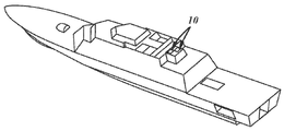
도 1은 2개의 지대지 미사일 시스템을 포함하는 지대지 미션 모듈을 운반하는 함정의 사시도이다.
도 2는 종래 기술의 3개의 운반 및 발사 유도 모듈을 포함하는 종래 기술의 지대지 미션 모듈의 사시도이다.
도 3은 2개의 지대지 미사일 시스템이 보이도록 절단된 도 1의 지대지 미션 모듈의 수직방향 도면이다.
도 4는 도 3의 지대지 미사일 시스템들 중 하나의 수직방향 도면이다.
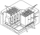
도 5는 도 3의 지대지 미사일 시스템의 3개의 운반 및 발사 유도 모듈들 중 하나가 부분적으로 절단된 수직방향 도면이다.
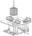
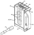
도 6은 도 5의 운반 및 발사 유도 모듈이 부분적으로 분해된 수직방향 도면이고, 셸 커버(shell cover)와 모듈 리드(module lid)는 모듈에 의해 내부로 운반된 미사일을 드러내도록 제거되어 있다.
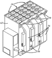
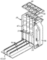
도 7은 도 5의 운반 및 발사 유도 모듈의 수직방향 도면이고, 미사일, 셸 커버 및 모듈 리드는 제거되어 있다.
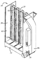
도 8은 도 7의 운반 및 발사 유도 모듈이 부분적으로 분해된 수직방향 도면이고, 모듈의 미사일 운반 벽의 전방 및 후방 구조적 스킨 부분은 운반 벽의 내부를 드러내도록 분리되어 있다.
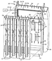
도 9는 셸 커버가 분리되어 있는 운반 및 발사 유도 모듈의 단편을 부분적으로 절단한 평면도이다.
도 10은 발사 유도 모듈의 미사일 운반 벽과 셸 커버 사이의 리니어 웨지 시일 인터페이스(linear wedge seal interface)가 나타나 있는 도 9의 동그라미친 영역의 확대도이다.
도 11은 도 10의 리니어 웨지 시일의 등축도이다.
도 12는 도 10의 리니어 웨지 시일의 측면도이고, 시일이 맞닿음해제된 포지션에 있는 것으로 나타나 있다.
도 13은 도 12의 라인 13-13을 따라 절단된 도 10의 리니어 웨지 시일의 단면도이고, 리니어 웨지 시일이 그 맞닿음해제된 포지션에 있는 상태로 위치결정되어 있는 리니어 웨지 시일의 리니어 후크가 나타나 있다.
도 14는 도 10의 리니어 웨지 시일의 단면도이고, 리니어 웨지 시일이 그 맞닿은 포지션에 있는 상태로 위치결정되어 있는 리니어 후크가 나타나 있다. BRIEF DESCRIPTION OF THE DRAWINGS Various features and advantages of the present invention will become apparent to those of ordinary skill in the art in view of the following detailed description and drawings of one or more embodiments of the invention.
BRIEF DESCRIPTION OF THE DRAWINGS Figure 1 is a perspective view of a ship carrying a ground-based mission module including two surface-to-ground missile systems.
2 is a perspective view of a prior art ground station mission module including three prior art conveyance and launch guidance modules.
FIG. 3 is a vertical view of the ground mission module of FIG. 1 cut so that two surface-to-surface missile systems are visible.
Figure 4 is a vertical view of one of the surface-to-surface missile systems of Figure 3;
Figure 5 is a partially cut away vertical view of one of the three transport and launch induction modules of the ground-to-land missile system of Figure 3;
FIG. 6 is a vertical, partially exploded view of the transport and launch induction module of FIG. 5, with the shell cover and module lid removed to reveal the missiles carried inward by the module.
FIG. 7 is a vertical view of the delivery and launch module of FIG. 5, with missiles, shell covers, and module leads removed.
FIG. 8 is a vertical view in which the conveying and launching module of FIG. 7 is partially exploded and the front and rear structural skin portions of the missile carrying wall of the module are separated to reveal the interior of the carrying wall.
Fig. 9 is a plan view partially cut away of a fragment of the delivery and launch induction module in which the shell cover is detached. Fig.
FIG. 10 is an enlarged view of the circle-shaped area of FIG. 9 in which a linear wedge seal interface between the missile carrying wall of the launch induction module and the shell cover is shown.
11 is an isometric view of the linear wedge seal of Fig.
Fig. 12 is a side view of the linear wedge seal of Fig. 10 with the seal shown in the disengaged position.
Fig. 13 is a cross-sectional view of the linear wedge seal of Fig. 10 cut along line 13-13 of Fig. 12, showing a linear hook of a linear wedge seal positioned with the linear wedge seal in its un- have.
Figure 14 is a cross-sectional view of the linear wedge seal of Figure 10, showing a linear hook positioned with the linear wedge seal in its abutting position.
다수의 미사일 운반 및 발사 유도 모듈은 대체로 도 1과 도 3 내지 도 8에 나타나 있다. 모듈(10)은 도 7에 가장 잘 나타나 있는 바와 같이 대체로 평행한 8개의 미사일 발사 레일(12)을 포함할 수 있지만, 다른 실시예에서는 다른 개수의 레일(12)이 포함되어 있을 수 있다. 레일(12)은, 예컨대 M299 미사일 발사 시스템에서 사용된 타입일 수 있다. 도 5와 도 6에 나타나 있는 바와 같이, 각각의 레일(12)은, 예컨대 AGM-114L 롱바우 헬파이어 미사일(Longbow HELLFIRE missile)과 같은 미사일(14)을 운반하고 이러한 미사일(14)의 발사를 유도하도록 구성되어 있을 수 있다.A number of missile transport and launch modules are generally shown in Figures 1 and 3-8. The
도 7과 도 8에 가장 잘 나타나 있는 바와 같이, 모듈(10)은, 미사일 발사 레일(12)을 레일(12)로부터의 미사일 운반 및 발사를 고려한 각각의 포지션과 배향으로 운반하는 공통 미사일 운반 벽(16)을 포함할 수도 있다. 공통 미사일 운반 벽(16)은 개별적으로 캐니스터화된 미사일을 수용할 필요가 없게 하고, 예컨대 연안 전투함 수직 발사 시스템(Littoral CombatShip Vertical Launch System; CSVLS) 적용처에서의 미사일(14) 패킹 밀도를 증가시킴으로써 모듈 질량과 풋프린트를 줄인다.As best seen in Figures 7 and 8, the
도 8과 도 9에 나타나 있는 바와 같이, 운반 벽(16)은 운반 벽(16)의 대체로 평행하게 떨어져 이격된 전방 및 후방 구조적 스킨들(18, 20)에 의해 형성된 운반 벽 코어(17)를 구비할 수 있다. 스킨들(18, 20)은 패스너(22)에 의해 각각의 외주 에지 둘레에 함께 접합될 수 있고, 구조적 스킨(structural skin)들 중 하나 또는 이들 모두의 외주 에지 둘레에 형성된 채널(26)에 수용되는 고무 O-링 개스킷(24)을 포함할 수 있다. 개스킷(24)은 운반 벽 코어(17)를 닫으면서 밀착하도록 스킨들(18, 20)의 외주 에지들 사이에 끼워질 수 있다. 운반 벽 스킨들(18, 20)은 미사일 운반 적하물의 운반과 분배시 함께 작동하도록 구성될 수 있다. 운반 벽 구조적 스킨(18, 20)은 알루미늄 판으로 기계가공될 수 있고, 다른 실시예에서는 적합한 재료로 된 적합한 수단으로 형성될 수 있다. 8 and 9, the
도 7과 도 8에 나타나 있는 바와 같이, 레일(12)은 운반 벽(16)의 전방 및 후방 구조적 스킨들(18, 20) 사이에 분배될 수 있고, 운반 벽(16)의 전방 및 후방 구조적 스킨들(18, 20)에 의해 운반될 수 있다. 8개의 레일(12)들 중 4개는 운반 벽(16)의 전방 스킨(18)에 의해 운반될 수 있고, 나머지 4개의 레일(12)들은 운반 벽(16)의 후방 스킨(20)에 의해 운반될 수 있다. 복수의 발사 레일(12)들의 발사 레일(12)은 측면방향으로 이격되어 있을 수 있고, 운반 벽(16)의 전방 및 후방 스킨(18, 20) 상에 서로에 대해 대체로 평행하게 배향되어 있을 수 있다. 7 and 8, the
운반 벽(16)에 구조적 강성을 제공하기 위해서, 전방 및 후방 구조적 스킨(18, 20)은 도 8에 나타나 있는 바와 같이 스킨들(18, 20)의 내측 표면으로부터 안쪽으로 일체로 돌출된 하드 포인트(28)들을 남기도록 기계가공될 수 있다. 하드 포인트(28)들은 스킨들(18, 20)이 함께 닫히는 경우 서로 맞닿도록 구성될 수 있다. 그 대신 또는 하드 포인트(28)들에 더하여, 운반 벽(16)은 강성을 증강시키기 위해서 전방 및 후방 구조적 스킨들(18, 20) 사이에 배치되는 충진재(filler)(29)를 구비할 수 있다. 충진재(29)는, 예컨대 알루미늄 하니콤을 구비할 수 있고, 또는, 예컨대 노멕스(Nomex®)를 구비하는 내열 재료를 구비할 수 있다. To provide structural rigidity to the
도 8에 나타나 있는 바와 같이, 모듈(10)은 스프링클러 노즐(30)을 포함할 수 있는데, 스프링클러 노즐은 운반 벽(16)의 전방 및 후방 구조적 스킨들(18, 20)에 의해 운반되고 운반 벽(16)의 전방 및 후방 구조적 스킨들(18, 20) 사이에 분배된다. 이러한 16개의 노즐(30)들이 본 실시예에서는 전방 및 후방 구조적 스킨들(18, 20) 사이에 분배되어 있지만, 다른 실시예에서는 적합한 개수의 스프링클러 노즐(30)들이 사용될 수 있다. 각각의 스프링클러 노즐(30)은 유체 공급장치(33)에 연결될 수 있는 스프링클러 파이핑(32)에 연결될 수 있다. 스프링클러 파이핑(32)은 화재 진압용 유체와 같은 유체가 스프링클러 노즐(30)들에 전달되고 스프링클러 노즐(30)들을 통해 배분되도록 운반 벽 코어(17)와 운반 벽 구조적 스킨들(18, 20)을 지나는 유체 통로를 제공하도록 구성될 수 있다. 스프링클러 노즐(30)은 미사일 배기 화염을 진압하는 방식과 방향으로 유체를 배분하도록 구성될 수 있다. 스프링클러 노즐(30)은 어떤 타입의 미사일(14)이든 모듈(10)에 의해 운반될 수 있고 모듈(10)로부터 발사될 수 있는 안전 요건을 만족하는 방식으로 실행되도록 선택될 수 있고 구성될 수 있고 그리고/또는 위치결정될 수 있다. 예를 들어, 노즐(30)은 레일(12)에 의해 운반되는 미사일(14)의 압력 용기 부분 및/또는 탄두와 같은 중요한 구성요소들을 적시고 냉각시킬 수 있는 패턴으로 유체를 분무하도록 구성될 수 있다. 노즐(30)은 마찬가지로 또는 이와 달리 원하는 영역과 구성요소의 대부분을 커버하도록 분무 패턴을 안내하는데 중력이 도움이 되게 하기 위해서 운반 벽(16) 위에 비교적 높게 위치될 수 있다. 8, the
도 8에 나타나 있는 바와 같이, 스프링클러 파이핑(32)은 유체 공급장치(33)로부터 운반 벽(16) 쪽으로 뻗어있는 외부 부분(34)과, 운반 벽 코어(17)를 통해 뻗어있는 내부 부분(36)을 포함할 수 있다. 내부 부분(36)은, 구조적 스킨들(18, 20)의 내측 표면들 중 적어도 하나로부터 일체로 뻗어있을 뿐만 아니라 고무 시일 스트립(38)을 파이핑 벽 또는 마주하는 내측 표면에 대하여 가압하여 구조적 스킨들(18, 20) 사이에 유체 채널을 형성하는, 내부 기계가공된 파이핑 벽들을 구비할 수 있다. 8, the sprinkler piping 32 includes an outer portion 34 extending from the
스프링클러 파이핑(32)은 운반 벽 구조적 스킨들(18, 20)의 외주 에지들 사이에 배치되어 있는 관통 인터페이스(penetration interface)(미도시)를 더 구비할 수 있다. 관통 인터페이스는 운반 벽 구조적 스킨들(18, 20)의 외주 에지들 사이에 밀착을 유지하면서 외부 및 내부 스프링클러 파이핑 부분들(34, 36) 사이에 유체가 통하도록 구성될 수 있다. 관통 인터페이스는, 예컨대 유체 튜브 케이블과 같은 당해 기술분야에 알려진 적합한 인터페이스를 구비할 수 있는데, 이 유체 튜브 케이블은 운반 벽 구조적 스킨들(18, 20) 사이에 뻗어있고 글랜드 너트에 의해 밀착된다. 이와 달리, 관통 인터페이스는 운반 벽 구조적 스킨들(18, 20) 중 하나 또는 모두에 장착되고 밀착되는 영구적이거나 순간적인 연결해제 커넥터를 구비하는 벌크헤드 인터페이스(bulkhead interface)를 구비한다. The sprinkler piping 32 may further include a penetration interface (not shown) disposed between the peripheral edges of the carrier wall
모듈(10)은 운반 벽 코어(17) 내부에 건조한 환경을 유지하기 위해서 장기 보관용 건조제를 운반 벽 코어(17) 내부로 운반하도록 구성된 건조제 홀더 구조물(42)을 포함할 수 있다. 도 8에 나타나 있는 바와 같이, 건조제 홀더 구조물(42)은 건조제 재료를 코어(17) 내부의 유리한 위치에 지원하도록 운반 벽 스킨들(18, 20)의 내측 표면들 속에 기계가공될 수 있다. The
모듈(10)은 도 8에 나타나 있는 바와 같이 운반 벽 코어(17)에 배치되어 있는 환경 센서(44)들을 포함할 수 있다. 환경 센서(44)들은 유지상태 및 안전 요건을 모니터링하기 위해서 온도, 습도, 충격, 진동 등과 같은 코어(17) 내부의 상태를 모니터링하도록 구성될 수 있다. The
도 8에는 운반 벽(16)이 케이블웨이 벽(48)들을 구비하는 일체형 케이블웨이(46)를 포함할 수 있는 것으로 나타나 있는데, 이 케이블웨이 벽(48)들은 구조적 스킨들(18, 20) 중 적어도 하나의 내측 표면으로부터 일체로 뻗어있을 뿐만 아니라 고무 시일 스트립(38)을 마주하는 내측 표면 또는 케이블웨이 벽에 대하여 가압하여 구조적 스킨들(18, 20) 사이에 케이블 채널을 형성한다. 케이블웨이 벽(48)들은 운반 벽 코어(17)를 통과할 수 있고, 미사일 중앙 케이블링과 같은 케이블링(미도시)을 수용하도록 구성된 채널을 형성하도록 함께 작동될 수 있는데, 이 미사일 중앙 케이블링은 레일(12) 상에 장착된 미사일(14)을 M299 미사일 발사 시스템의 M299 발사장치 전자기기 어셈블리(Launcher Electroics Assemby; LEA)와 같은 발사장치 전자기기 어셈블리에 연결한다. 미사일 중앙 케이블링은 군수품 제어 및 모니터링과 관련된 신호를 운반할 수 있다. 일체형 케이블웨이(46)는 마찬가지로 또는 이와 달리, 환경 센서(44) 및/또는 접근/침입 센서와 같은 다른 시스템 및/또는 레일 관련 전기기계 디바이스를 제어하고 그리고/또는 전력공급하기 위하여 레일(12)을 발사장치 전자기기 어셈블리에 연결하는 레일 케이블링을 수용할 수 있다. It is shown in Figure 8 that the
도 3 내지 도 9에 나타나 있는 바와 같이, 모듈(10)은 그 사이에서 공통 운반 벽(16)을 운반하는 대체로 평행하게 떨어져 이격된 한 쌍의 단부 벽(50)들을 포함할 수 있다. 도 3에 나타나 있는 바와 같이, 단부 벽(50)들은 미사일 운반 및 발사 모듈(10)을 운반하도록 구성된 함정 탑재 구조물과 같은 모듈 지원용 구조물(52)의 장착용 인터페이스에 의해 운반되도록 구성될 수 있다. 이러한 함정 탑재 구조물(52)은 베이스 함정 구조물(Base Ship Structure; BSS)과 같은 부착 지점 하드웨어 또는 약간 수정된 버전의 하드웨어를 운반할 수 있는 세트를 이루는 C 채널 또는 I 빔을 포함할 수 있다. As shown in Figs. 3-9, the
도 5 내지 도 8에 나타나 있는 바와 같이, 모듈(10)은 단부 벽(50)들 사이에서 단부 벽(50)들에 의해 운반되는 플리넘(plenum)(54)을 포함할 수 있다. 플리넘(54)은 모듈(10)로부터 발사되고 있는 미사일(14)로부터의 배기 가스를 수용할 뿐만 아니라 다시 안내하도록 구성되고 위치결정될 수 있다. 플리넘(54)은 도 6에 가장 잘 나타나 있는 바와 같이 모듈(10)이 장착되어 있는 함정의 갑판과 수평인 흡기 해치(uptake hatch)(58)를 통해 가스를 위로 안내하도록 구성된 발사용 슈트(discharge chute)(56) 쪽으로 배기 가스를 안내할 수 있다. 플리넘(54)은 미사일 배기가스가 악영향을 미치는 플리넘(54)의 내부 표면 영역 상에 실리콘처리된 융제(siliconized ablatives)를 포함할 수 있고, 다른 내부 표면 영역 상에는 다른 타입의 융제를 포함할 수 있다. As shown in FIGS. 5-8, the
도 3 내지 도 6에 나타나 있는 바와 같이, 모듈(10)은 모듈 리드(60)(또는 갑판 인터페이스)를 포함할 수 있는데, 이 모듈 리드는 적합한 수단에 의해 운반 벽(16)의 정상 에지로 운반되거나 적합한 수단에 의해 운반 벽(16)의 정상 에지에 연결되거나 적합한 수단에 의해 운반 벽(16)의 정상 에지에 밀착된다. 모듈 리드(60)는 적합한 수단에 의해 단부 벽(50)들의 정상 에지에 연결될 수 있고, 적합한 수단에 의해 단부 벽(50)들의 정상 에지에 밀착될 수 있다. 모듈 리드(60)는 도 3에 나타나 있는 바와 같이 갑판과 같은 높이에 장착될 수 있고, 미사일(14)이 그것을 통해 발사될 때 찢겨 개방되도록 구성된 가요성 막을 지탱할 수 있는 강성의 직사각형 개구 그리드(opening grid)를 포함할 수 있다. 운반 벽(16), 모듈 리드(60), 플리넘(54) 및 단부 벽(50)은 구조적 강성을 이들 요소들 사이에 제공하도록 그리고 적하물을 운반 벽(16)과 플리넘으로부터, 모듈(10)을 운반할 수 있는 함정 탑재 구조물과 같은 구조물의 장착용 인터페이스 쪽으로 이송하도록 상호연결될 수 있다. As shown in Figures 3-6, the
도 7과 도 8에 가장 잘 나타나 있는 바와 같이, 단부 벽(50)들은 각각의 정상 단부에서나 그 인접한 곳에서 적합한 수단에 의해 모듈 리드(60)에 연결될 수 있다. 단부 벽(50)들의 각각의 하부 단부들에서나 그 인접한 곳에서, 단부 벽(50)들은 플리넘(54)에 연결될 수 있다. 단부 벽(50)들은 내측 수직방향 중간 영역을 따라 운반 벽(16)의 각각의 측면 에지들에 연결될 수 있다. 따라서 단부 벽(50)들은 모듈(10)로부터 발사되고 있는 미사일(14)로부터의 배기 가스를 수용할 뿐만 아니라 다시 안내하기 위해서 그리고 운반 벽(16), 모듈 리드와, 모듈(10)을 운반하는 구조물의 장착용 인터페이스들 사이에 구조적 강성을 제공하기 위해서 플리넘(54)을 적소에서 지탱할 수 있다.As best seen in Figures 7 and 8, the
모듈(10)은, 각각의 전방 및 후방 모듈 개구들에 걸쳐 제거가능하게 배치되어 있을 뿐만 아니라 각각의 전방 및 후방 모듈 개구들을 닫는 대체로 직사각형인 전방 및 후방 셸 커버(62)들을 포함할 수 있다. 전방 모듈 개구는 모듈 리드(60)의 전방 에지들, 단부 벽(50)들 및 플리넘(54)에 의해 형성될 수 있다. 후방 개구는 모듈 리드(60)의 후방 에지들, 단부 벽(50)들과 플리넘(54)에 의해 형성될 수 있다. 셸 커버(62)는 레일(12) 및/또는 레일(12)에 의해 운반되는 미사일(14)에 대한 접근을 제공하도록 제거가능할 수 있다. The
도 5와 도 6에 가장 잘 나타나 있는 바와 같이, 각각의 셸 커버(62)는, 모듈 개구(65)에 걸쳐 제거가능하게 배치되어 있을 뿐만 아니라 모듈 개구(65)를 닫을 수 있는 형상을 가지는 메인 커버 패널(64), 및 메인 커버 패널(64)로부터 일체로 뻗어있는 3개의 미사일 분리기 패널(66)을 구비할 수 있다. 미사일 분리기 패널(66)들은 떨어져 이격될 수 있고, 운반 벽(16)에 맞닿도록 구성될 수 있고, 이러한 미사일(14)들을 발사 동안 다른 것의 배기가스로부터 보호하기 위해서 운반 벽(16)과 셸 커버(62) 사이의 공간을, 레일(12)에 의해 운반되는 미사일(14)을 개별적으로 수용하기 위한 셀(cell; 작은 방과 같은 공간 등을 말하며, 이는 명세서 전체로 동일함)들로 분할하도록 구성될 수 있다. 도면에는 3개의 미사일 분리기 패널(66)이 4개의 미사일(14)을 셸 커버(62) 마다 구분하는데 사용되는 것으로 나타나 있지만, 다른 실시예에서는 그러한 실시예를 포함하여 다양한 개수의 레일(12), 미사일(14) 등에 대응하는 더 많거나 더 적은 분리기 패널(66)로 구성되는 셸 커버(62)를 이용할 수 있다.As best seen in Figures 5 and 6, each of the shell covers 62 is removably disposed over the
분리기 패널(66)들은 도 9 내지 도 14에 나타나 있는 바와 같이, 예컨대 맞물림 리니어 후크(76)를 수용할 뿐만 아니라 맞닿도록 구성된 리니어 웨지 시일(68)에 의해 운반 벽 구조적 스킨들의 외측 표면들에 대하여 밀착될 수 있다. 리니어 웨지 시일(68)은 슬라이딩 클램프(72), 브레이스(70), 및 슬라이딩 클램프(72)를 브레이스(70)에 부착하도록 구성된 장착용 볼트(74)를 구비할 수 있다. 슬라이딩 클램프(72)는 장착용 볼트(74)들을 수용하도록 구성된 사선형 슬롯들을 포함할 수 있으므로, 슬라이딩 클램프(72)는 도 11과 도 12에 나타나 있는 바와 같이 브레이스(70)로부터 멀어지거나 접근할 수 있는 경로를 따라 장착용 볼트(74) 둘레에서 미끄럼이동할 수 있다. 리니어 웨지 시일(68)은 브레이스(70)와 슬라이딩 클램프(72) 사이에 맞물림 리니어 후크(76)를 수용하도록 구성될 수 있고, 도 14에 나타나 있는 바와 같이 브레이스(70)와 리니어 후크(76)로 압축 밀착이 형성될 때까지 사선형 슬롯(76)에 의해 허용되는 경로를 따라 슬라이딩 클램프(70)를 미끄럼이동시킴으로써 브레이스(70)와 슬라이딩 클램프(72) 사이에 리니어 후크(76)를 밀착시키도록 구성될 수 있다. 도 9에 나타나 있는 바와 같이, 리니어 후크(76)나 리니어 웨지 시일(68) 중 하나는 운반 벽(16), 단부 벽(50) 및/또는 메인 커버 패널(64)이나 분리기 패널(66)에 의해 운반될 수 있으므로, 각각의 리니어 후크(76)는 커버 패널(64)이 설치되는 경우 리니어 웨지 시일(68)에 맞닿을 수 있다. 도면에서, 웨지 시일(68)과 리니어 후크(76)는 각각의 커버 패널(64)이 커버 패널의 리니어 후크(76)를 운반 벽(16)과 단부 벽(60) 상에 설치된 웨지 시일(68) 속 단부방향으로 미끄럼이동시킴으로써 설치될 수 있도록 구성된다. 환언하자면, 커버 패널(64)은 모듈(10)의 정상에 걸쳐 수직방향으로 설치될 수 있다. 그러나, 다른 실시예에서, 웨지 시일(68)은 셸 커버(62)가 모듈(10)의 측면으로부터, 또는 다른 방해받지 않는 방향으로부터 각각의 모듈 개구(65) 속에 설치될 수 있도록 배향될 수 있다.
LCSVLS의 종래의 구성은, 예컨대 2개의 지대지 미사일 시스템(Surface-to-Surface Missile Systems; SSMS)을 구비하는 지대지 미션 모듈(Surface-to-Surface Mission Module; SSMM)을 포함할 수 있다. 각각의 SSMS는 3개의 미사일 발사 모듈(10), 및 M299 MLA와 같은 발사장치 관리 어셈블리(Launcher Management Assembly; LMA)를 포함할 수 있다. 각각의 모듈(10)은 SSMS로부터 개별적으로 제거가능할 수 있고, 뻗어있는 미사일(14)이 있는 모듈(10)이 제거되거나 미사일(14)과 함께 재선적되게 할 수 있고 또는 미리 선적된 모듈(10)과 교체되게 할 수 있다. The conventional configuration of the LCSVLS may include a Surface-to-Surface Mission Module (SSMM) with, for example, two Surface-to-Surface Missile Systems (SSMS). Each SSMS may include three
상술된 바와 같은 다수의 미사일 운반 및 발사 유도 모듈은 미사일을 안전하게 보관하는 것, 미사일을 모니터링하는 것, 및 미사일을 발사하는 것이 가능한 공간 및 중량 효율적인 플랫폼을 제공한다. 본 명세서는 본 발명의 한계를 기술하는 것이 아니라 특허청구범위에서 인용되는 발명의 실시예들을 설명할 뿐이다. 따라서, 본 명세서의 용어들은 오로지 설명하기 위한 것이고 제한하려는 것은 아니다. 명백하게도, 본 명세서가 교시하는 사항으로부터 본 발명을 수정하는 것도 가능하다. 청구항의 범위 내라면 상술된 것 이외의 발명도 실시할 수 있을 것이다.A number of missile transport and launch modules, such as those described above, provide a space-efficient and weight-efficient platform for safely storing missiles, monitoring missiles, and launching missiles. This specification does not describe the limitations of the present invention, but merely illustrates embodiments of the invention cited in the claims. Accordingly, the terminology herein is for the purpose of description and is not intended to be limiting. Obviously, it is also possible to modify the invention from the teachings of this specification. It will be understood that the invention may be practiced otherwise than as described within the scope of the claims.
Claims (15)
복수의 미사일 발사 레일을 레일로부터의 미사일 운반 및 발사를 고려한 각각의 포지션과 배향으로 운반하는 공통 미사일 운반 벽;
을 구비하는 것을 특징으로 하는 다수의 미사일 운반 및 발사 유도 모듈.A plurality of missile launch rails, each rail configured to carry a missile and direct the launch of the missile; And
A common missile carrying wall carrying a plurality of missile launch rails in respective positions and orientations taking into account missile transport and launch from the rails;
And a plurality of missile carrying and launching modules.
레일은 운반 벽의 마주하여 향하고 있는 전방 및 후방 측면들 사이에서 분배되고, 운반 벽의 마주하여 향하고 있는 전방 및 후방 측면들에 의해 운반되는 것을 특징으로 하는 다수의 미사일 운반 및 발사 유도 모듈.The method according to claim 1,
Wherein the rails are distributed between opposing front and rear sides of the carrier wall and are carried by the facing forward and rear sides of the carrier wall.
운반 벽은 미사일 운반 적하물의 운반과 분배시 함께 작동하도록 구성된 운반 벽의 대체로 평행하게 떨어져 이격된 전방 및 후방 구조적 스킨들에 의해 형성된 운반 벽 코어를 구비하는 것을 특징으로 하는 다수의 미사일 운반 및 발사 유도 모듈.3. The method of claim 2,
Characterized in that the carrier wall comprises a carrier wall core formed by substantially parallel spaced apart front and rear structural skins of the carrier wall configured to cooperate during delivery and dispensing of the missile carrier dumper. module.
운반 벽은 전방 및 후방 구조적 스킨들 사이에 배치되는 충진재를 구비하는 것을 특징으로 하는 다수의 미사일 운반 및 발사 유도 모듈.The method of claim 3,
Wherein the carrier wall comprises a filler disposed between the front and rear structural skins.
운반 벽에 의해 운반되고, 미사일 배기 화염을 진압하는 방식과 방향으로 유체를 방출하도록 구성된 적어도 하나의 스프링클러 노즐; 및
유출구 단부에서 스프링클러 노즐에 연결되고 유입구 단부에서 유체 공급장치에 연결가능한 스프링클러 파이핑으로서, 유체 공급장치로부터 스프링클러 노즐 쪽으로 운반 벽 코어와 유체를 위한 운반 벽 구조적 스킨을 지나는 유체 통로를 제공하도록 구성되어 있는, 스프링클러 파이핑;
을 포함하는 것을 특징으로 하는 다수의 미사일 운반 및 발사 유도 모듈.The method according to claim 1,
At least one sprinkler nozzle carried by the carrier wall and configured to discharge fluid in a manner and direction to counteract the missile exhaust flame; And
A sprinkler piping connected to the sprinkler nozzle at the outlet end and connectable to the fluid supply at the inlet end, the sprinkler piping configured to provide a fluid passageway through the transport wall structural skin for the fluid and the transport wall core from the fluid supply device towards the sprinkler nozzle, Sprinkler piping;
And a plurality of missile carrying and launching modules.
스프링클러 파이핑은, 운반 벽 구조적 스킨들 중 적어도 하나의 내측 표면으로부터 일체로 뻗어있을 뿐만 아니라 마주하는 구조적 스킨 내측 표면에 대하여 밀착하여 운반 벽 구조적 스킨들 사이에 유체 채널을 형성하는, 파이핑 벽들을 구비하는 것을 특징으로 하는 다수의 미사일 운반 및 발사 유도 모듈.6. The method of claim 5,
Sprinkler piping includes piping walls that extend integrally from the inner surface of at least one of the carrier wall structural skins and also form a fluid channel between the carrier wall structural skins in intimate contact with the opposing structural skin inner surface And a plurality of missile carrying and launching modules.
운반 벽 코어 내부에서 운반 벽에 의해 운반되는 건조제를 더 구비하는 것을 특징으로 하는 다수의 미사일 운반 및 발사 유도 모듈.The method of claim 3,
Further comprising a desiccant carried by the carrier wall within the carrier wall core.
운반 벽에 의해 운반되고 운반 벽 코어 내부에 배치되며 온도, 습도, 충격이나 진동으로 이루어진 상태에 관한 그룹 중에서 선택되는 하나 이상의 코어 내부의 상태를 모니터링하도록 구성된 적어도 하나의 환경 센서를 더 구비하는 것을 특징으로 하는 다수의 미사일 운반 및 발사 유도 모듈.The method of claim 3,
Characterized by further comprising at least one environmental sensor carried by the carrier wall and arranged inside the carrier wall core and configured to monitor a condition within one or more cores selected from the group of conditions relating to temperature, humidity, shock or vibration And a plurality of missile carrying and launching modules.
운반 벽은, 운반 벽 코어를 통과하고 케이블링을 수용하도록 구성된 일체형 케이블웨이를 포함하는 것을 특징으로 하는 다수의 미사일 운반 및 발사 유도 모듈.The method of claim 3,
Wherein the carrier wall comprises an integral cableway configured to pass through the carrier wall core and to receive the cabling.
그 사이에서 공통 벽을 운반하고 모듈 지원용 구조물의 장착용 인터페이스에 의해 운반되도록 구성된 떨어져 이격된 한 쌍의 단부 벽들을 더 구비하는 것을 특징으로 하는 다수의 미사일 운반 및 발사 유도 모듈.The method according to claim 1,
Further comprising a pair of spaced-apart end walls configured to carry a common wall therebetween and carried by the mounting interface of the module support structure.
단부 벽들에 의해 운반되고 모듈로부터 발사되고 있는 미사일로부터의 배기 가스를 수용할 뿐만 아니라 다시 안내하도록 구성되고 위치결정되는 플리넘을 더 구비하는 것을 특징으로 하는 다수의 미사일 운반 및 발사 유도 모듈.11. The method of claim 10,
Further comprising a plenum configured and positioned to receive and re-direct the exhaust gas from the missiles carried by the end walls and firing from the modules. ≪ Desc / Clms Page number 13 >
모듈은 운반 벽과 단부 벽들에 의해 운반되는 모듈 리드를 포함하고,
운반 벽, 커버, 플리넘 및 단부 벽들은 구조적 강성을 이들 요소들 사이에 제공하도록 그리고 적하물을 운반 벽과 플리넘으로부터, 모듈을 운반할 수 있는 구조물의 장착용 인터페이스 쪽으로 이송하도록 상호연결되는 것을 특징으로 하는 다수의 미사일 운반 및 발사 유도 모듈.12. The method of claim 11,
The module includes a module lead carried by the carrying wall and the end walls,
The carrying wall, the cover, the plenum, and the end walls are interconnected to provide structural stiffness therebetween and to transfer the load from the carrying wall and plenum towards the mounting interface of the structure that can transport the module And a plurality of missile carrying and launching modules.
단부 벽들은 모듈 리드, 플리넘 및 운반 벽의 측면 에지들에 연결되는 것을 특징으로 하는 다수의 미사일 운반 및 발사 유도 모듈.13. The method of claim 12,
Wherein the end walls are connected to the side edges of the module leads, the plenum, and the carrier wall.
각각의 전방 및 후방 모듈 개구들에 걸쳐 제거가능하게 배치되어 있을 뿐만 아니라 각각의 전방 및 후방 모듈 개구들을 닫는 전방 및 후방 셸 커버들을 더 구비하고,
전방 개구는 모듈 리드의 전방 에지들, 단부 벽들 및 플리넘에 의해 형성되고,
후방 개구는 모듈 리드의 후방 에지들, 단부 벽들과 플리넘에 의해 형성되는 것을 특징으로 하는 다수의 미사일 운반 및 발사 유도 모듈.11. The method of claim 10,
Further comprising front and rear shell covers that are removably disposed over each of the front and rear module openings and that close each of the front and rear module openings,
The front opening is defined by the front edges, end walls and plenum of the module lead,
Wherein the rear opening is formed by the rear edges of the module lid, the end walls and the plenum.
각각의 셸 커버는:
모듈 개구에 걸쳐 제거가능하게 배치되어 있을 뿐만 아니라 모듈 개구를 닫을 수 있는 형상을 가지는 메인 커버 패널; 및
메인 커버 패널로부터 일체로 뻗어있고, 떨어져 이격되어 있으며, 운반 벽에 맞닿을 뿐만 아니라 운반 벽과 셸 커버 사이의 공간을, 레일에 의해 운반되는 미사일을 수용하기 위한 셀들로 분할하도록 구성된, 복수의 미사일 분리기 패널;
을 구비하는 것을 특징으로 하는 다수의 미사일 운반 및 발사 유도 모듈.15. The method of claim 14,
Each shell cover is:
A main cover panel that is removably disposed over the module opening and has a shape capable of closing the module opening; And
A plurality of spaced apart spaced-apart, spaced-apart, spaced-apart spacers between the carrying wall and the shell cover for dividing the cells into cells for receiving the missiles carried by the rails, Separator panel;
And a plurality of missile carrying and launching modules.
Applications Claiming Priority (3)
| Application Number | Priority Date | Filing Date | Title |
|---|---|---|---|
| US13/970,865 US9360277B2 (en) | 2013-08-20 | 2013-08-20 | Multiple missile carriage and launch guidance module |
| US13/970,865 | 2013-08-20 | ||
| PCT/US2014/051439 WO2015053859A1 (en) | 2013-08-20 | 2014-08-18 | Multiple missile carriage and launch guidance module |
Publications (1)
| Publication Number | Publication Date |
|---|---|
| KR20160056322A true KR20160056322A (en) | 2016-05-19 |
Family
ID=52479200
Family Applications (1)
| Application Number | Title | Priority Date | Filing Date |
|---|---|---|---|
| KR1020167007175A KR20160056322A (en) | 2013-08-20 | 2014-08-18 | Multiple missile carriage and launch guidance module |
Country Status (6)
| Country | Link |
|---|---|
| US (1) | US9360277B2 (en) |
| EP (1) | EP3036495B1 (en) |
| JP (1) | JP6559131B2 (en) |
| KR (1) | KR20160056322A (en) |
| IL (1) | IL244208B (en) |
| WO (1) | WO2015053859A1 (en) |
Cited By (1)
| Publication number | Priority date | Publication date | Assignee | Title |
|---|---|---|---|---|
| KR101978490B1 (en) * | 2017-11-23 | 2019-08-28 | 주식회사 한화 | Cable shielding structure of rocket pod and rocket pod having the same |
Families Citing this family (6)
| Publication number | Priority date | Publication date | Assignee | Title |
|---|---|---|---|---|
| US11015903B2 (en) * | 2011-06-08 | 2021-05-25 | American Technical Coatings, Inc. | Enhanced ballistic protective system |
| US20150345900A1 (en) | 2014-05-28 | 2015-12-03 | Chief Of Naval Research, Office Of Counsel | Missile Launcher System |
| FR3069522A1 (en) * | 2017-07-27 | 2019-02-01 | Dcns | NAVAL PLATFORM OF THE TYPE COMPRISING A MISSILE PIT |
| CN107478106A (en) * | 2017-08-16 | 2017-12-15 | 董兰田 | Orbit launching ground effect wing is to extra large guided missile |
| CN112484569A (en) * | 2020-11-24 | 2021-03-12 | 中国航空工业集团公司沈阳飞机设计研究所 | Airborne embedded vertical launching device |
| RU2767097C1 (en) * | 2021-06-16 | 2022-03-16 | Федеральное государственное казенное военное образовательное учреждение высшего образования "Военный учебно-научный центр Военно-Морского Флота "Военно-морская академия им. Адмирала Флота Советского Союза Н.Г. Кузнецова" | Universal shipborne vertical launcher |
Family Cites Families (26)
| Publication number | Priority date | Publication date | Assignee | Title |
|---|---|---|---|---|
| US2809559A (en) * | 1943-04-02 | 1957-10-15 | Charles C Lauritsen | Rocket projector |
| NL96336C (en) * | 1955-10-04 | |||
| US3113486A (en) * | 1959-06-10 | 1963-12-10 | Kongelbeck Sverre | Turrent launcher |
| US3106132A (en) | 1961-03-06 | 1963-10-08 | Earl E Biermann | Launcher |
| US3138989A (en) * | 1963-02-21 | 1964-06-30 | James C Lewis | Retractable rail assemblies |
| US3738220A (en) * | 1971-04-01 | 1973-06-12 | Us Army | Flexible-fixed launch and aiming shoe/self releasing electrical and/or pyrotechnic connector for rockets |
| US3724321A (en) * | 1971-04-21 | 1973-04-03 | P Le Chevalier | Apparatus for positioning and securing a projectile holder on its pad |
| US3899953A (en) * | 1972-03-21 | 1975-08-19 | Constr Navales Ind | Self-propelled fin stabilized projectiles and launchers therefor |
| DE2930555C2 (en) * | 1979-07-27 | 1983-11-10 | Steinbock Gmbh, 8052 Moosburg | Storage and transport system for guided missiles and the like. |
| US4470336A (en) * | 1982-08-05 | 1984-09-11 | General Dynamics, Pomona Division | Armored missile launch/shipping container |
| USH213H (en) * | 1986-06-02 | 1987-02-03 | The United States Of America As Represented By The Secretary Of The Navy | Disiccant plug for missile launcher |
| US5115711A (en) * | 1991-03-25 | 1992-05-26 | Fmc Corporation | Missile canister and method of fabrication |
| US5837919A (en) * | 1996-12-05 | 1998-11-17 | The United States Of America As Represented By The Secretary Of The Navy | Portable launcher |
| US6079310A (en) * | 1996-12-05 | 2000-06-27 | The United States Of America As Represented By The Secretary Of The Navy | Portable launcher |
| US6230604B1 (en) * | 1997-01-14 | 2001-05-15 | United Defense, L.P. | Concentric canister launcher |
| JPH10300393A (en) * | 1997-04-21 | 1998-11-13 | Japan Radio Co Ltd | Projectile launcher and method for judging separation of projectile |
| US5847307A (en) * | 1997-06-24 | 1998-12-08 | Northrop Grumman Corporation | Missile launcher apparatus |
| FR2781771B1 (en) * | 1998-08-03 | 2001-02-09 | Mediterranee Const Ind | METHOD OF SETTING A TUBE IN A TUBULAR HOUSING, PARTICULARLY A MISSILE LAUNCH TUBE |
| US6125734A (en) * | 1998-10-14 | 2000-10-03 | The United States Of America As Represented By The Secretary Of The Navy | Multi-warfare area launcher |
| JP3546148B2 (en) * | 1998-12-07 | 2004-07-21 | 三菱重工業株式会社 | Flying body cooling device |
| US6755111B2 (en) * | 2001-06-27 | 2004-06-29 | Lockheed Martin Corporation | Missile launcher cell with exhaust gas uptake ducts, and array of such missile launcher cells |
| US6742433B2 (en) * | 2001-10-12 | 2004-06-01 | Raytheon Company | Launcher platform |
| JP2004226007A (en) * | 2003-01-23 | 2004-08-12 | Japan Steel Works Ltd:The | Missile canister |
| FR2917493B1 (en) * | 2007-06-13 | 2009-09-25 | Dcn Sa | MISSILE CONTAINER MAINTENANCE STRUCTURE OF A MISSILE VERTICAL LAUNCH DEVICE |
| US8534177B2 (en) * | 2010-03-01 | 2013-09-17 | Lockheed Martin Corporation | System and method for shock isolation in a launch system |
| US8468924B2 (en) * | 2010-12-16 | 2013-06-25 | Lockheed Martin Corporation | Stowable elevating trainable launcher (SETL) |
-
2013
- 2013-08-20 US US13/970,865 patent/US9360277B2/en not_active Expired - Fee Related
-
2014
- 2014-08-18 EP EP14851875.6A patent/EP3036495B1/en not_active Not-in-force
- 2014-08-18 WO PCT/US2014/051439 patent/WO2015053859A1/en active Application Filing
- 2014-08-18 KR KR1020167007175A patent/KR20160056322A/en not_active Application Discontinuation
- 2014-08-18 JP JP2016536346A patent/JP6559131B2/en not_active Expired - Fee Related
-
2016
- 2016-02-21 IL IL244208A patent/IL244208B/en active IP Right Grant
Cited By (1)
| Publication number | Priority date | Publication date | Assignee | Title |
|---|---|---|---|---|
| KR101978490B1 (en) * | 2017-11-23 | 2019-08-28 | 주식회사 한화 | Cable shielding structure of rocket pod and rocket pod having the same |
Also Published As
| Publication number | Publication date |
|---|---|
| US20150053073A1 (en) | 2015-02-26 |
| IL244208A0 (en) | 2016-04-21 |
| JP2016531266A (en) | 2016-10-06 |
| JP6559131B2 (en) | 2019-08-14 |
| WO2015053859A1 (en) | 2015-04-16 |
| IL244208B (en) | 2019-09-26 |
| EP3036495A4 (en) | 2017-04-19 |
| EP3036495B1 (en) | 2018-03-28 |
| EP3036495A1 (en) | 2016-06-29 |
| US9360277B2 (en) | 2016-06-07 |
Similar Documents
| Publication | Publication Date | Title |
|---|---|---|
| KR20160056322A (en) | Multiple missile carriage and launch guidance module | |
| US10203180B2 (en) | Missile canister gated obturator | |
| US7614334B2 (en) | Common services pod for dispensing countermeasure devices | |
| US8443707B2 (en) | Self-contained munition gas management system | |
| WO2022154211A1 (en) | Storage box for loading battery cells | |
| JP4058042B2 (en) | Missile launcher cells with exhaust gas intake ducts and rows of these missile launcher cells | |
| WO2010001051A3 (en) | Principle for the integration of missile-based weapon systems on a fixed ramp for stealth surface vessels in order to counter asymmetric threats | |
| US8237588B1 (en) | Ammunition stowage magazine | |
| US8266999B1 (en) | Mobile vertical missile launcher | |
| US8245874B1 (en) | Slider-hinge door | |
| US7159501B1 (en) | Stackable in-line surface missile launch system for a modular payload bay | |
| RU2207968C2 (en) | Multi-purpose highly manoeuvrable supersonic aircraft, its airframe, equipment and systems | |
| RU2382314C1 (en) | Modular multi-seat vertical-start ship launcher | |
| WO2009130384A1 (en) | Weapon system | |
| US11225333B2 (en) | Fuel tank inerting system | |
| GB2121149A (en) | Missile housing and launch arrangement | |
| US11715963B1 (en) | Battery storage container and wellness system | |
| RU96123485A (en) | MULTI-PURPOSE HIGH-MANEUVERED SUPERSONIC AIRPLANE, ITS PLANER UNITS, EQUIPMENT AND SYSTEMS | |
| US9855805B2 (en) | Buoyancy module for a military vehicle | |
| KR20140049284A (en) | Connecting device for loading weapon in submarine | |
| RU138066U1 (en) | Combat vehicle of a volley fire reactive system | |
| RU44175U1 (en) | MODULAR MULTI-SINGLE SHIP STARTING VERTICAL START-UP | |
| RU2306520C2 (en) | Transportation and loading pot of tank gun past-turret automatic loader | |
| RU2210520C1 (en) | Submarine vessel | |
| JP2005231483A (en) | Bulletproof structure and bulletproof method for vessel |
Legal Events
| Date | Code | Title | Description |
|---|---|---|---|
| A201 | Request for examination | ||
| E902 | Notification of reason for refusal | ||
| E601 | Decision to refuse application |