KR20160053631A - An electronic disk brake - Google Patents
An electronic disk brake Download PDFInfo
- Publication number
- KR20160053631A KR20160053631A KR1020140152943A KR20140152943A KR20160053631A KR 20160053631 A KR20160053631 A KR 20160053631A KR 1020140152943 A KR1020140152943 A KR 1020140152943A KR 20140152943 A KR20140152943 A KR 20140152943A KR 20160053631 A KR20160053631 A KR 20160053631A
- Authority
- KR
- South Korea
- Prior art keywords
- spindle
- piston
- nut
- disk
- carrier
- Prior art date
Links
Images


Classifications
-
- F—MECHANICAL ENGINEERING; LIGHTING; HEATING; WEAPONS; BLASTING
- F16—ENGINEERING ELEMENTS AND UNITS; GENERAL MEASURES FOR PRODUCING AND MAINTAINING EFFECTIVE FUNCTIONING OF MACHINES OR INSTALLATIONS; THERMAL INSULATION IN GENERAL
- F16D—COUPLINGS FOR TRANSMITTING ROTATION; CLUTCHES; BRAKES
- F16D55/00—Brakes with substantially-radial braking surfaces pressed together in axial direction, e.g. disc brakes
- F16D55/02—Brakes with substantially-radial braking surfaces pressed together in axial direction, e.g. disc brakes with axially-movable discs or pads pressed against axially-located rotating members
- F16D55/22—Brakes with substantially-radial braking surfaces pressed together in axial direction, e.g. disc brakes with axially-movable discs or pads pressed against axially-located rotating members by clamping an axially-located rotating disc between movable braking members, e.g. movable brake discs or brake pads
- F16D55/224—Brakes with substantially-radial braking surfaces pressed together in axial direction, e.g. disc brakes with axially-movable discs or pads pressed against axially-located rotating members by clamping an axially-located rotating disc between movable braking members, e.g. movable brake discs or brake pads with a common actuating member for the braking members
- F16D55/225—Brakes with substantially-radial braking surfaces pressed together in axial direction, e.g. disc brakes with axially-movable discs or pads pressed against axially-located rotating members by clamping an axially-located rotating disc between movable braking members, e.g. movable brake discs or brake pads with a common actuating member for the braking members the braking members being brake pads
- F16D55/226—Brakes with substantially-radial braking surfaces pressed together in axial direction, e.g. disc brakes with axially-movable discs or pads pressed against axially-located rotating members by clamping an axially-located rotating disc between movable braking members, e.g. movable brake discs or brake pads with a common actuating member for the braking members the braking members being brake pads in which the common actuating member is moved axially, e.g. floating caliper disc brakes
-
- F—MECHANICAL ENGINEERING; LIGHTING; HEATING; WEAPONS; BLASTING
- F16—ENGINEERING ELEMENTS AND UNITS; GENERAL MEASURES FOR PRODUCING AND MAINTAINING EFFECTIVE FUNCTIONING OF MACHINES OR INSTALLATIONS; THERMAL INSULATION IN GENERAL
- F16D—COUPLINGS FOR TRANSMITTING ROTATION; CLUTCHES; BRAKES
- F16D65/00—Parts or details
- F16D65/14—Actuating mechanisms for brakes; Means for initiating operation at a predetermined position
- F16D65/16—Actuating mechanisms for brakes; Means for initiating operation at a predetermined position arranged in or on the brake
- F16D65/18—Actuating mechanisms for brakes; Means for initiating operation at a predetermined position arranged in or on the brake adapted for drawing members together, e.g. for disc brakes
-
- F—MECHANICAL ENGINEERING; LIGHTING; HEATING; WEAPONS; BLASTING
- F16—ENGINEERING ELEMENTS AND UNITS; GENERAL MEASURES FOR PRODUCING AND MAINTAINING EFFECTIVE FUNCTIONING OF MACHINES OR INSTALLATIONS; THERMAL INSULATION IN GENERAL
- F16D—COUPLINGS FOR TRANSMITTING ROTATION; CLUTCHES; BRAKES
- F16D2121/00—Type of actuator operation force
- F16D2121/18—Electric or magnetic
- F16D2121/24—Electric or magnetic using motors
-
- F—MECHANICAL ENGINEERING; LIGHTING; HEATING; WEAPONS; BLASTING
- F16—ENGINEERING ELEMENTS AND UNITS; GENERAL MEASURES FOR PRODUCING AND MAINTAINING EFFECTIVE FUNCTIONING OF MACHINES OR INSTALLATIONS; THERMAL INSULATION IN GENERAL
- F16D—COUPLINGS FOR TRANSMITTING ROTATION; CLUTCHES; BRAKES
- F16D2125/00—Components of actuators
- F16D2125/18—Mechanical mechanisms
- F16D2125/20—Mechanical mechanisms converting rotation to linear movement or vice versa
- F16D2125/34—Mechanical mechanisms converting rotation to linear movement or vice versa acting in the direction of the axis of rotation
- F16D2125/40—Screw-and-nut
Abstract
Description
More particularly, the present invention relates to an electronic disk brake, and more particularly, to a disk brake which is configured such that when the piston is advanced by hydraulic pressure during service braking to separate the piston and the nut spindle, the nut spindle vibrates and collides with the inner wall of the spindle And an anti-vibration spring on the nut spindle to prevent vibration.
The brake is a braking device used for decelerating or stopping the speed of a running vehicle. In recent years, an electronic parking brake (EPB) system for electronically controlling the driving of a parking brake has been used, and is mounted on a normal disk brake to perform a parking brake function. In addition, the vehicle is equipped with ABS (Anti-lock Brake System) or ESC (Electronic Stability Control), which is an auxiliary safety device to prevent slipping of the vehicle by controlling the fluid pressure during braking, and is used together with the electronic parking brake system.
1 is a view showing a schematic configuration of an electronic disc brake according to the prior art.
1, an electronic disk brake according to the related art includes a
The pair of
A
The
When the
When the
When the
SUMMARY OF THE INVENTION The present invention has been made to solve the above problems, and it is an object of the present invention to provide an elastic unit capable of absorbing and preventing an impact on the rim of the nut spindle so that the spindle unit of the brake and the piston do not impact on the vibration, Which can prevent the nut spindle from colliding with the spindle while vibrating at the inner wall of the spindle.
According to an aspect of the present invention, there is provided a caliper housing comprising: a disk; a carrier having a pair of pad plates for pressing both sides of the disk; a caliper housing provided on a side surface of the carrier; A piston rotatably supported on the spindle shaft, the spindle shaft being rotatable by a motor, the spindle shaft being coupled to the spindle shaft to rotate the spindle shaft; And a spindle unit configured to reciprocate in a direction of an axis of the piston, the spindle unit comprising: an elastic unit for holding the nut spindle so as to be spaced apart from the inner wall of the piston, between the nut spindle and the piston; May be further included.
In a preferred embodiment of the present invention, the elastic unit may be composed of a coupling ring coupled to the body of the nut spindle and a plurality of legs branched from the coupling ring and extending to an outer edge of the nut.
In a preferred embodiment of the present invention, the leg portion may be configured to contact the inner wall of the piston while being extended to round outside the edge of the nut portion.
In a preferred embodiment of the present invention, an end of the leg portion is formed to be rounded toward the center of the nut spindle.
According to the present invention, since the elastic unit is provided between the nut spindle and the piston, the elastic unit catches the vibration of the nut spindle and maintains a constant interval between the piston and the nut spindle, There is an advantage that it is possible to prevent the nut spindle floating in the inner space of the piston from being vibrated while hitting against the piston.
BRIEF DESCRIPTION OF THE DRAWINGS Fig. 1 is a diagram showing a schematic configuration of an electronic disc brake according to the prior art; Fig.
2 is a sectional view of an electronic disc brake according to the present invention.
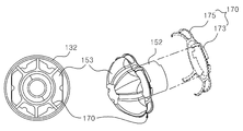
3 is a perspective view showing a state in which the elastic unit is provided in the nut spindle according to the present invention.
Hereinafter, preferred embodiments of the present invention will be described in detail with reference to the accompanying drawings.
FIG. 2 is a sectional view of an electronic disc brake according to the present invention, and FIG. 3 is a perspective view showing a state in which an elastic unit is provided on a nut spindle according to the present invention.
2 and 3, an electronic disk brake according to the present invention includes a
The
The
The
The
A
The above-described structure is a general structure of a conventional electronic disc brake, and a detailed description thereof will be omitted. The structure of the electronic disk brake according to the present invention is not limited to the above-described structure. If the
The electronic disk brake according to the present invention has an elastic unit 170 (not shown) which keeps the
The
The plurality of
In a preferred embodiment of the present invention, the
The
Although the present invention has been described in connection with certain exemplary embodiments, it is to be understood that the invention is not limited to the disclosed exemplary embodiments. Therefore, the scope of the present invention should not be limited by the described embodiments, but should be defined by the appended claims and equivalents thereof.
100: Disk 110: Pad plate
120: carrier 130: caliper housing
131: Ping refuse 132: Piston
133: cylinder 140: motor
150: spindle unit 151: spindle shaft
152: Nut spindle 153: Nut
160: Reducer 170: Elastic unit
173: coupling ring 175: leg
Claims (4)
A carrier having a pair of pad plates for pressing both sides of the disk;
A caliper housing provided on a side surface of the carrier,
A piston incorporated in the caliper housing and pressing the pad plate while reciprocating at one side of the carrier;
And a spindle unit which is provided in the piston and rotates by a motor, and a spindle unit which is screwed to the spindle shaft and reciprocates in a rotating direction of the spindle shaft,
Further comprising an elastic unit disposed between the nut spindle and the piston to keep the nut spindle away from the inner wall of the piston.
Wherein the elastic unit is constituted by a coupling ring coupled to the body of the nut spindle and a plurality of leg portions branched from the coupling ring and extending to an outer edge of the nut portion.
And the leg portion is configured to come into contact with the inner wall of the piston while being extended to round the outside of the edge of the nuts.
And an end of the leg portion is formed to be rounded in the center direction of the nut spindle.
Priority Applications (1)
| Application Number | Priority Date | Filing Date | Title |
|---|---|---|---|
| KR1020140152943A KR20160053631A (en) | 2014-11-05 | 2014-11-05 | An electronic disk brake |
Applications Claiming Priority (1)
| Application Number | Priority Date | Filing Date | Title |
|---|---|---|---|
| KR1020140152943A KR20160053631A (en) | 2014-11-05 | 2014-11-05 | An electronic disk brake |
Publications (1)
| Publication Number | Publication Date |
|---|---|
| KR20160053631A true KR20160053631A (en) | 2016-05-13 |
Family
ID=56023445
Family Applications (1)
| Application Number | Title | Priority Date | Filing Date |
|---|---|---|---|
| KR1020140152943A KR20160053631A (en) | 2014-11-05 | 2014-11-05 | An electronic disk brake |
Country Status (1)
| Country | Link |
|---|---|
| KR (1) | KR20160053631A (en) |
Cited By (3)
| Publication number | Priority date | Publication date | Assignee | Title |
|---|---|---|---|---|
| KR20180135718A (en) * | 2017-06-13 | 2018-12-21 | 주식회사 만도 | Electronic disc brake |
| US20210010553A1 (en) * | 2018-03-28 | 2021-01-14 | Foundation Brakes France Sas | Lock nut |
| CN114514386A (en) * | 2019-06-05 | 2022-05-17 | 大陆特维斯股份有限公司 | Centering mechanism for a brake piston with a disc brake |
-
2014
- 2014-11-05 KR KR1020140152943A patent/KR20160053631A/en active Search and Examination
Cited By (4)
| Publication number | Priority date | Publication date | Assignee | Title |
|---|---|---|---|---|
| KR20180135718A (en) * | 2017-06-13 | 2018-12-21 | 주식회사 만도 | Electronic disc brake |
| US20210010553A1 (en) * | 2018-03-28 | 2021-01-14 | Foundation Brakes France Sas | Lock nut |
| US11686360B2 (en) * | 2018-03-28 | 2023-06-27 | Foundation Brakes France Sas | Lock nut |
| CN114514386A (en) * | 2019-06-05 | 2022-05-17 | 大陆特维斯股份有限公司 | Centering mechanism for a brake piston with a disc brake |
Similar Documents
| Publication | Publication Date | Title |
|---|---|---|
| KR20160053631A (en) | An electronic disk brake | |
| KR101922476B1 (en) | Electric caliper brake with parking function | |
| KR20100137765A (en) | Brake apparatus for bicycle | |
| CN114876975A (en) | Auxiliary brake device of drum brake | |
| KR101904713B1 (en) | Brake for vehicle | |
| CN103738450A (en) | Mechanical double-acting disc brake | |
| KR20150091859A (en) | Caliper brake for a vehicle | |
| JP2014085010A (en) | Disc type parking brake sealing member | |
| KR20170137318A (en) | Disc brake | |
| KR20150128273A (en) | Disk brake | |
| KR20140059666A (en) | Brake for vehicle | |
| KR100771004B1 (en) | Disc brake | |
| KR20120104740A (en) | Disc brake | |
| KR20110064766A (en) | Disk brake | |
| KR100502515B1 (en) | Disc brake and Pad shim | |
| KR100808478B1 (en) | Disc brake | |
| KR100994009B1 (en) | Disk Brake | |
| KR100622473B1 (en) | disk brake structure of vehicle | |
| KR20090043207A (en) | Disk brake for vehicle | |
| CN104595395A (en) | Eccentric wheel type mechanical braking device | |
| KR101488569B1 (en) | Disk Brake including Fixed type Caliper For Vehicle | |
| KR20110125137A (en) | Disk brake | |
| KR20040079719A (en) | Disk Type Brake | |
| KR20110064765A (en) | Disk brake | |
| KR100349539B1 (en) | Disk brake |
Legal Events
| Date | Code | Title | Description |
|---|---|---|---|
| A201 | Request for examination | ||
| E902 | Notification of reason for refusal | ||
| AMND | Amendment | ||
| E601 | Decision to refuse application | ||
| AMND | Amendment |