KR20160051992A - Lamp Apparatus For An Automobile - Google Patents
Lamp Apparatus For An Automobile Download PDFInfo
- Publication number
- KR20160051992A KR20160051992A KR1020140149626A KR20140149626A KR20160051992A KR 20160051992 A KR20160051992 A KR 20160051992A KR 1020140149626 A KR1020140149626 A KR 1020140149626A KR 20140149626 A KR20140149626 A KR 20140149626A KR 20160051992 A KR20160051992 A KR 20160051992A
- Authority
- KR
- South Korea
- Prior art keywords
- lens
- light
- vehicle
- upper reflector
- shield
- Prior art date
Links
- 239000000463 material Substances 0.000 claims description 13
- 238000000034 method Methods 0.000 claims description 13
- 230000000903 blocking effect Effects 0.000 claims description 5
- 230000003287 optical effect Effects 0.000 claims description 5
- 238000001914 filtration Methods 0.000 claims description 4
- 239000007769 metal material Substances 0.000 claims description 4
- 238000005286 illumination Methods 0.000 description 7
- 230000008569 process Effects 0.000 description 4
- 230000000694 effects Effects 0.000 description 3
- 238000002347 injection Methods 0.000 description 3
- 239000007924 injection Substances 0.000 description 3
- 230000008901 benefit Effects 0.000 description 2
- 230000008859 change Effects 0.000 description 2
- 229910052736 halogen Inorganic materials 0.000 description 2
- 150000002367 halogens Chemical class 0.000 description 2
- 230000003044 adaptive effect Effects 0.000 description 1
- 230000008021 deposition Effects 0.000 description 1
- 230000008034 disappearance Effects 0.000 description 1
- 239000011521 glass Substances 0.000 description 1
- 238000012986 modification Methods 0.000 description 1
- 230000004048 modification Effects 0.000 description 1
- 238000000465 moulding Methods 0.000 description 1
- 230000001151 other effect Effects 0.000 description 1
- 230000010287 polarization Effects 0.000 description 1
- 238000002834 transmittance Methods 0.000 description 1
Images


Classifications
-
- F—MECHANICAL ENGINEERING; LIGHTING; HEATING; WEAPONS; BLASTING
- F21—LIGHTING
- F21S—NON-PORTABLE LIGHTING DEVICES; SYSTEMS THEREOF; VEHICLE LIGHTING DEVICES SPECIALLY ADAPTED FOR VEHICLE EXTERIORS
- F21S41/00—Illuminating devices specially adapted for vehicle exteriors, e.g. headlamps
- F21S41/20—Illuminating devices specially adapted for vehicle exteriors, e.g. headlamps characterised by refractors, transparent cover plates, light guides or filters
- F21S41/29—Attachment thereof
- F21S41/295—Attachment thereof specially adapted to projection lenses
-
- F—MECHANICAL ENGINEERING; LIGHTING; HEATING; WEAPONS; BLASTING
- F21—LIGHTING
- F21S—NON-PORTABLE LIGHTING DEVICES; SYSTEMS THEREOF; VEHICLE LIGHTING DEVICES SPECIALLY ADAPTED FOR VEHICLE EXTERIORS
- F21S41/00—Illuminating devices specially adapted for vehicle exteriors, e.g. headlamps
- F21S41/20—Illuminating devices specially adapted for vehicle exteriors, e.g. headlamps characterised by refractors, transparent cover plates, light guides or filters
- F21S41/285—Refractors, transparent cover plates, light guides or filters not provided in groups F21S41/24 - F21S41/2805
-
- F—MECHANICAL ENGINEERING; LIGHTING; HEATING; WEAPONS; BLASTING
- F21—LIGHTING
- F21S—NON-PORTABLE LIGHTING DEVICES; SYSTEMS THEREOF; VEHICLE LIGHTING DEVICES SPECIALLY ADAPTED FOR VEHICLE EXTERIORS
- F21S41/00—Illuminating devices specially adapted for vehicle exteriors, e.g. headlamps
- F21S41/60—Illuminating devices specially adapted for vehicle exteriors, e.g. headlamps characterised by a variable light distribution
- F21S41/63—Illuminating devices specially adapted for vehicle exteriors, e.g. headlamps characterised by a variable light distribution by acting on refractors, filters or transparent cover plates
- F21S41/64—Illuminating devices specially adapted for vehicle exteriors, e.g. headlamps characterised by a variable light distribution by acting on refractors, filters or transparent cover plates by changing their light transmissivity, e.g. by liquid crystal or electrochromic devices
-
- F—MECHANICAL ENGINEERING; LIGHTING; HEATING; WEAPONS; BLASTING
- F21—LIGHTING
- F21W—INDEXING SCHEME ASSOCIATED WITH SUBCLASSES F21K, F21L, F21S and F21V, RELATING TO USES OR APPLICATIONS OF LIGHTING DEVICES OR SYSTEMS
- F21W2107/00—Use or application of lighting devices on or in particular types of vehicles
- F21W2107/10—Use or application of lighting devices on or in particular types of vehicles for land vehicles
Landscapes
- Engineering & Computer Science (AREA)
- General Engineering & Computer Science (AREA)
- Chemical & Material Sciences (AREA)
- Crystallography & Structural Chemistry (AREA)
- Non-Portable Lighting Devices Or Systems Thereof (AREA)
Abstract
Description
본 발명은 차량용 조명 장치에 관한 것으로, 보다 상세하게는 최소한의 공정과 비용으로 다양한 빔 패턴을 구현할 수 있는 차량용 조명 장치에 관한 것이다.BACKGROUND OF THE
일반적으로 차량용 헤드램프는 차량 전방에 설치되는 헤드램프와, 차량 후바엥 설치되는 리어램프를 포함한다. Generally, a headlamp for a vehicle includes a head lamp installed in front of the vehicle and a rear lamp installed in the rear of the vehicle.
헤드램프는 전방을 조명하여 야간 운행 중에 전방을 비추는 램프이며, 눈, 비, 안개 시에 다른 차량이나 보행자가 차량을 쉽게 인지할 수 있도록 하는 안개등과, 차량의 진행 방향을 알리는 방향지시등을 포함한다.A headlamp includes a fog lamp that illuminates the front and illuminates the front during nighttime operation, a fog lamp that allows other vehicles or pedestrians to recognize the vehicle easily in the case of snow, rain, and fog, and a turn signal lamp that indicates the traveling direction of the vehicle .
한편, 자동 배광 가변형 전조등 시스템(Adaptive Front-Lighting System, 이하, AFLS이라 한다.)이란, 시가지, 고속도로, 교차로, 악천후 등 도로상황과 날씨에 따른 주행조건에 맞춰 자동으로 조명 각도와 밝기를 조절하는 시스템을 말한다.An Adaptive Front-Lighting System (hereinafter referred to as AFLS) is a system that automatically adjusts lighting angle and brightness according to road conditions such as a city area, a highway, an intersection, System.
AFLS 헤드 램프는, 통상적으로, 램프 모듈이 스위블링(Swiveling)구동 및 레벨링(Leveling)구동 하도록 설계된다. 스위블링 구동이란, 램프 모듈의 좌우 방향으로 회전하는 움직임을 의미하며, 레벨링 구동이란, 램프 모듈이 상하 방향으로 회전하는 움직임을 의미한다. 또한, AFLS 헤드 램프는, 주행조건에 맞추어 빔 패턴을 변경하기 위하여 쉴드를 구동하도록 설계될 수 있다.The AFLS headlamp is typically designed such that the lamp module drives a swiveling and a leveling. The swiveling drive means a movement of the lamp module in the left and right direction, and the leveling drive means the movement of the lamp module in the up and down direction. In addition, the AFLS headlamp can be designed to drive the shield to change the beam pattern in accordance with driving conditions.
하지만 다양한 패턴 변화를 얻기 위해서는 쉴드를 구동하여야 한다. 그러기 위해서는, 쉴드의 형상이 복잡해지고, 이를 움직이기 위해 구동 모터 등이 다양한 구조물이 추가됩에 따라 모듈의 크기가 커지며, 램프내 공간을 많이 필요로 한다. 이는, 모듈 구조를 복잡하게 만들고, 디자인 자유도를 떨어뜨리며, 부품이 추가됨에 따라 원가를 높이며, 양한 기능을 구현하기에 제한 됩니다. 또한, 부품의 문제 발생시, 패턴을 수정하기 위해서는 쉴드의 금형을 변경하는 등 추가 비용/시간이 크게 발생하게 되는 문제점이 있다.However, in order to obtain various pattern changes, the shield must be driven. In order to do this, the shape of the shield becomes complicated, and as the various motors, such as a driving motor, are added to move the shield, the size of the module increases and a large space is required in the lamp. This complicates the structure of the module, lowers the freedom of design, increases costs as parts are added, and is limited to implementing a few functions. Further, when a problem of a part occurs, there is a problem that an extra cost / time such as a change of a mold of a shield is large in order to correct a pattern.
본 발명이 해결하고자 하는 과제는 차량용 조명 장치를 제공하는데 있다. SUMMARY OF THE INVENTION It is an object of the present invention to provide a vehicle lighting device.
쉴드에서 구현되는 다양한 기능의 배광 패턴을 하나의 쉴드 디스플레이부로 구현하고, 렌즈, 상부 리플렉터, 홀더를 일체로 사출성형하여, 부품의 중량 및 공정을 감소하는데 그 목적이 있다 할 것이다.It is an object of the present invention to implement light distribution patterns of various functions implemented in a shield as one shield display unit and to injection-mold the lens, the upper reflector, and the holder integrally to reduce the weight and process of the parts.
본 발명의 과제들은 이상에서 언급한 과제들로 제한되지 않으며, 언급되지 않은 또 다른 과제들은 아래의 기재로부터 당업자에게 명확하게 이해될 수 있을 것이다.The problems of the present invention are not limited to the above-mentioned problems, and other problems not mentioned can be clearly understood by those skilled in the art from the following description.
상기 과제를 달성하기 위하여, 본 발명의 실시예에 따른 차량용 조명 장치에 있어서, 차량에 배치되어 빛을 방출하는 광원과 광원이 삽입 고정되고, 광원으로부터 생성된 빛을 차량 전방으로 반사시키는 상부 리플렉터와 상부 리플렉터의 하부에 구비되고, 광원으로부터 생성된 빛을 차량 전방으로 반사시키는 하부 리플렉터와상부 리플렉터와 일체로 형성된 홀더에 안착된 렌즈와 상부 리플렉터 내부에 구비되고, 전기적 신호로 다수의 배광 배턴을 형성하여 쉴드 이미지를 디스플레이하는 쉴드 디스플레이부와 렌즈 전면에 구비되고, 렌즈로 투과되는 빛의 일부를 차단하는 필터를 포함한다.In order to achieve the above object, in a vehicle lighting apparatus according to an embodiment of the present invention, a light source and a light source, which are disposed in a vehicle and emit light, are inserted and fixed, and an upper reflector A lower reflector disposed under the upper reflector, a lower reflector for reflecting the light generated from the light source to the front of the vehicle, a lens seated in the holder integrally formed with the upper reflector, and a plurality of light distribution blunts formed in the upper reflector, A shield display unit for displaying a shield image, and a filter provided on the front surface of the lens for blocking a part of light transmitted through the lens.
또한, 쉴드 디스플레이부는, 렌즈의 후면과 차량의 전후방향으로 연장되는 광축 상에 배치된 제2초점 사이에 구비된 것을 포함한다.Further, the shield display portion includes a portion provided between a rear surface of the lens and a second focal point disposed on an optical axis extending in the front-rear direction of the vehicle.
또한, 쉴드 디스플레이부는, 상부 리플렉터 및 하부 리플렉터에 각각 형성된 돌출 리브를 포함한다.Further, the shield display portion includes protruding ribs formed respectively in the upper reflector and the lower reflector.
또한, 쉴드 디스플레이부는, 홀더의 상부면에 형성된 홀을 통해 배선된 것을 포함한다. In addition, the shield display portion includes the wiring through the hole formed in the upper surface of the holder.
또한, 쉴드 디스플레이부는, 상부 리플렉터의 상부면에 형성된 홀을 통해 배선된 것을 포함한다.In addition, the shield display section includes those wired through holes formed in the upper surface of the upper reflector.
또한, 렌즈 전면에 밀착되어 형성되고, 플렉서블 디스플레이 또는 필름으로 형성된 것을 포함한다.Further, it is formed in close contact with the front surface of the lens and includes a flexible display or a film.
또한, 필터는, 필터링 각도 및 영역을 조절하여 렌즈로 투과되는 빛을 필터링하는 것을 포함한다.The filter also includes filtering the light transmitted through the lens by adjusting the filtering angle and area.
또한, 렌즈, 상기 홀더 및 상기 상부 리플렉터는 일체로 사출성형되고, 플라스틱 재질로 형성된 것을 포함한다.Further, the lens, the holder, and the upper reflector are integrally injection-molded and include a plastic material.
또한, 하부 리플렉터는 플라스틱 재질 또는 금속 재질로 형성된 것을 포함한다.Further, the lower reflector includes a plastic material or a metal material.
기타 실시예들의 구체적인 사항들은 상세한 설명 및 도면들에 포함되어 있다.The details of other embodiments are included in the detailed description and drawings.
본 발명의 차량용 조명 장치에 따르면 다음과 같은 효과가 하나 혹은 그 이상 있다.The vehicle lighting apparatus of the present invention has one or more of the following effects.
첫째, 다양한 기능의 배광 패턴을 한 개의 쉴드 디스플레이부를 통해 구현이 가능하다.First, various light distribution patterns can be implemented through one shield display unit.
둘째, 렌즈의 재질을 유리 재질에서 플라스틱 재질로 변경하고, 리플렉터의 재질을 금속 재질에서 플라스틱 재질로 변경하여 부품의 중량을 감소 시킬 수 있다.Second, the weight of the part can be reduced by changing the material of the lens from a glass material to a plastic material, and changing the material of the reflector from a metal material to a plastic material.
셋째, 렌즈, 홀더, 상부 리플렉터를 일체로 사출성형 하여, 렌즈의 유동을 방지하고, 렌즈 후면에 쉴드 디스플레이부를 배치하여 쉴드 위치의 공차를 최소화 할 수 있다.Third, the lens, the holder, and the upper reflector are integrally injection molded to prevent the lens from flowing, and the shield display portion is disposed on the rear surface of the lens, thereby minimizing the tolerance of the shield position.
넷째, 렌즈, 홀더, 상부 리플렉터를 일체로 사출성형 하여 부품 조립 공정을 최소화 할 수 있다.Fourth, the lens assembly, the holder, and the upper reflector are integrally injection-molded to minimize the component assembling process.
다섯째, 쉴드가 조명 장치 모듈의 중간에 위치하지 않아 장애물이 사라짐으로 인해 반사면의 증착성이 향상될 수 있다.Fifth, since the shield is not located in the middle of the illumination device module, the deposition property of the reflecting surface can be improved due to the disappearance of the obstacle.
여섯째, 렌즈, 홀더, 상부 리플렉터를 일체로 사출성형 하여 종래의 쉴드를 움직이기 위해 사용되었던 부품을 삭제하여 중량을 감소 시킬 수 있다.Sixth, the lens, the holder, and the upper reflector can be integrally injection-molded to reduce the weight by deleting the parts used for moving the conventional shield.
일곱째, 렌즈, 홀더, 상부 리플렉터를 일체로 사출성형하여 렌즈의 유동을 방지할 수 있다.Seventh, the lens, the holder, and the upper reflector can be integrally injection molded to prevent the lens from flowing.
여덟째, 렌즈, 홀더, 상부 리플렉터를 일체로 사출성형함으로써, 반사율을 최대한 줄여 홀더에 의한 빛 튀김 현상을 방지하는 등 광학적 효과를 얻을 수 있다.Eighth, an optical effect can be obtained by integrally molding the lens, the holder, and the upper reflector by reducing the reflectance as much as possible to prevent the light from being splashed by the holder.
본 발명의 효과들은 이상에서 언급한 효과들로 제한되지 않으며, 언급되지 않은 또 다른 효과들은 청구범위의 기재로부터 당업자에게 명확하게 이해될 수 있을 것이다.The effects of the present invention are not limited to the effects mentioned above, and other effects not mentioned can be clearly understood by those skilled in the art from the description of the claims.
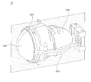
도 1은 본 발명에 따른 차량용 조명 장치를 나타낸 사시도이다.
도 2는 본 발명에 따른 차량용 조명 장치를 나타낸 사시도이다.
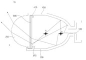
도 3은 본 발명에 따른 차량용 조명 장치를 나타낸 단면도이다.
도 4는 도 3의 구성 중 쉴드 디스플레이부의 배선을 나타낸 단면도이다.
도 5는 도 4의 구성 중 배선홀의 실시예를 나타낸 평면도이다.
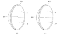
도 6은 도 3의 구성 중 쉴드 디스플레이부에 의한 쉴드 패턴 적용 예시를 나타낸 도면이다.
도 7은 본 발명에 따른 차량용 조명 장치의 작동 모습을 나타낸 단면도이다.
도 8은 본 발명에 따른 차량용 조명 장치의 구성 중 필터가 장착된 모습을 나타낸 단면도이다.1 is a perspective view showing a lighting device for a vehicle according to the present invention.
2 is a perspective view showing a lighting device for a vehicle according to the present invention.
3 is a cross-sectional view showing a lighting device for a vehicle according to the present invention.
4 is a cross-sectional view showing the wiring of the shield display portion in the configuration of FIG.
5 is a plan view showing an embodiment of a wiring hole in the configuration of FIG.
6 is a view illustrating an example of application of a shield pattern by the shield display unit in the configuration of FIG.
7 is a cross-sectional view showing an operation of a vehicle lighting apparatus according to the present invention.
8 is a cross-sectional view showing a structure of a lighting device for a vehicle according to the present invention, in which a filter is mounted.
본 발명의 이점 및 특징, 그리고 그것들을 달성하는 방법은 첨부되는 도면과 함께 상세하게 후술되어 있는 실시예들을 참조하면 명확해질 것이다. 그러나 본 발명은 이하에서 개시되는 실시예들에 한정되는 것이 아니라 서로 다른 다양한 형태로 구현될 수 있으며, 단지 본 실시예들은 본 발명의 개시가 완전하도록 하고, 본 발명이 속하는 기술분야에서 통상의 지식을 가진 자에게 발명의 범주를 완전하게 알려주기 위해 제공되는 것이며, 본 발명은 청구항의 범주에 의해 정의될 뿐이다. 명세서 전체에 걸쳐 동일 참조 부호는 동일 구성 요소를 지칭한다.BRIEF DESCRIPTION OF THE DRAWINGS The advantages and features of the present invention, and the manner of achieving them, will be apparent from and elucidated with reference to the embodiments described hereinafter in conjunction with the accompanying drawings. The present invention may, however, be embodied in many different forms and should not be construed as limited to the embodiments set forth herein. Rather, these embodiments are provided so that this disclosure will be thorough and complete, and will fully convey the scope of the invention to those skilled in the art. To fully disclose the scope of the invention to those skilled in the art, and the invention is only defined by the scope of the claims. Like reference numerals refer to like elements throughout the specification.
이하, 본 발명의 실시예들에 의하여 차량용 조명 장치를 설명하기 위한 도면들을 참고하여 본 발명에 대해 설명하도록 한다.Hereinafter, the present invention will be described with reference to the drawings for explaining a vehicle lighting apparatus according to embodiments of the present invention.
바람직한 차량용 조명 장치는 당해 기술분야에서 통상의 지식을 가진자에 의해 변경될 수 있으며, 본 실시예에서는 차량용 조명 장치인 경우이다.A preferred vehicle illumination device can be modified by a person skilled in the art, and in this embodiment is a case of a vehicle illumination device.
도 1은 본 발명에 따른 차량용 조명 장치를 나타낸 사시도이고, 도 2는 본 발명에 따른 차량용 조명 장치를 나타낸 사시도이고, 도 3은 본 발명에 따른 차량용 조명 장치를 나타낸 단면도이다.FIG. 1 is a perspective view showing a lighting apparatus for a vehicle according to the present invention, FIG. 2 is a perspective view showing a lighting apparatus for a vehicle according to the present invention, and FIG. 3 is a sectional view showing a lighting apparatus for a vehicle according to the present invention.
도 1을 참조하면, 본 발명의 실시예에 따른 차량용 조명 장치는 차량에 배치되어 빛을 방출하는 광원(100)과 광원(100)이 삽입 고정되고, 광원(100)으로부터 생성된 빛을 차량 전방으로 반사시키는 상부 리플렉터(400)와 상부 리플렉터(400)의 하부에 구비되고, 광원(100)으로부터 생성된 빛을 차량 전방으로 반사시키는 하부 리플렉터(500)와 상부 리플렉터(400)와 일체로 형성된 홀더(300)에 안착된 렌즈(200)와 상부 리플렉터(400) 내부에 구비되고, 전기적 신호로 다수의 배광 배턴을 형성하여 쉴드 이미지를 디스플레이하는 쉴드 디스플레이부(600)와 렌즈(200) 전면에 구비되고, 렌즈(200)로 투과되는 빛의 일부를 차단하는 필터(700)를 포함한다.1, a vehicle lighting apparatus according to an embodiment of the present invention includes a
광원(100)은 차량에 배치되어 빛을 방출 할 수 있다. 광원(11)은 빛을 내는 물체 또는 도구를 의미하며, 경우에 따라서는 빛을 받아 그것을 반사하는 물체를 이르기도 한다. 광원(100)은, 할로겐 램프 및 HDI 램프(High-Intensity Discharge Lamp)와 같은 벌브형 램프로 형성되어, 후술할 상부 리플렉터(400) 내부에 배치된다. 광원(100)은 벌브형으로 형성되기 때문에, 상부 리플렉터(400) 내에서 전후 방향으로 소정의 길이를 가지고 배치되어 LED(Light Emitting Diode)에 비해 발광 면이 넓게 되며, 이로인해 상부 리플렉터(400) 또는 하부 리플렉터(500)로부터 반사되는 빛의 난반사 영역을 증가시킨다. 광원(100)은 할로겐 램프 외에도 LED일 수 있다.The
광원(100)의 중심부에는 제1초점(F1)이 위치할 수 있다.A first focus F1 may be positioned at the center of the
렌즈(200)는 후술하는 상부 리플렉터(400)와 일체로 형성된 홀더(300)에 안착될 수 있다. 렌즈(200)의 후면에는 후술하는 쉴드 디스플레이부(600)가 구비될 수 있고, 렌즈(200)의 전면에는 후술하는 필터(700)가 구비될 수 있다. 자세한 내용은 후술한다. The
렌즈(200)는 상부 리플렉터(400) 또는 하부 리플렉터(500)로부터 반사되는 빛을 굴절시켜 외부로 배광하는 비구면 렌즈(200)로 형성될 수 있고, 후술하는 쉴드 디스플레이부(600)의 패턴 적용 방법에 따라 비정형 렌즈(200) 형성될 수 있다.The
렌즈(200)는 플라스틱 재질로 형성될 수 있다. 또한, 렌즈(200)는 광원(100)의 광축(Lx) 상에 배치될 수 있고, 광원(100)으로부터 방출된 빛을 차량 전방으로 방출 시킬 수 있다.The
홀더(300)는 후술하는 상부 리플렉터(400)와 일체로 형성될 수 있고, 렌즈(200)를 안착시킬 수 있다. 또한, 홀더(300)는 플라스틱 재질로 형성될 수 있다.The
상부 리플렉터(400)는 광원(100)이 삽입 고정되고, 광원(100)으로부터 생성된 빛을 차량 전방으로 반사시킬 수 있다. 보다 상세하게는, 광원(100)으로부터 생성되는 빛을 차량 전방으로 반사시키는 역할을 한다. 상부 리플렉터(400)는 내측면이 오목하게 함입되어 비구면(타원형)으로 형성된다.The
상부 리플렉터(400)는 플라스틱 재질로 형성될 수 있다.The
하부 리플렉터(500)는 상부 리플렉터(400)의 하부에 구비되고, 광원(100)으로부터 생성된 빛을 차량 전방으로 반사시킬 수 있다. 보다 상세하게는, 광원(100)으로부터 생성되는 빛을 차량 전방으로 반사시키는 역할을 한다. 하부 리플렉터(500)는 내측면이 오목하게 함입되어 비구면(타원형)으로 형성된다.The
하부 리플렉터(500)는 플라스틱 재질 또는 금속 재질로 형성될 수 있다.The
쉴드 디스플레이부(600)는 상부 리플렉터(400) 내부에 구비되고, 전기적 신호로 다수의 배광 패턴을 형성하여 쉴드 이미지를 디스플레이 할 수 있다.The
쉴드 디스플레이부(600)는 렌즈(200)의 후면과 차량의 전후방향으로 연장되는 광축(Lx) 상에 배치된 제2초점(F2) 사이에 구비될 수 있다. 즉, 렌즈(200) 후면과 제2초점(F2) 사이의 구간(L1)에 구비될 수 있다. 본 실시예에 따르면, 쉴드 디스플레이부(600)는 제2초점(F2)으로부터 빛이 방출하는 방향으로 10mm 이상 떨어진 거리를 유지하는 것이 바람직하다.
쉴드 디스플레이부(600)는 상부 리플렉터(400) 및 하부 리플렉터(500)에 각각 형성된 돌출리브(410, 510)에 의해 고정될 수 있다. 보다 상세하게는, 쉴드 디스플레이부(600)의 상부는 상부 리플렉터(400)의 돌출리브(410)에 의해 형성된 슬롯에 끼움결합되고, 쉴드 디스플레이부(600)의 하부는 하부 리플렉터(500)의 돌출리브(510)에 의해 형성된 슬롯에 끼움결합될 수 있다.The
쉴드 디스플레이부(600)는 비구면 렌즈(200)의 주요 배광 영역을 확인하고, 입력된 쉴드 형상을 프로그래밍하여 쉴드 디스플레이부(600)의 투과율을 조정하여 배광 포인트별 광도를 일부 조정할 수 있다.The
도 4는 도 3의 구성 중 쉴드 디스플레이부의 배선을 나타낸 단면도이고, 도 5는 도 4의 구성 중 배선홀의 실시예를 나타낸 평면도이다.Fig. 4 is a cross-sectional view showing the wiring of the shield display portion in the configuration of Fig. 3, and Fig. 5 is a plan view showing an embodiment of the wiring hole of the configuration of Fig.
도 4 및 도 5를 참조하면, 쉴드 디스플레이부(600)는 홀더(300)의 상부면에 형성된 제1배선홀(310)을 통해 배선되는 제1배선(610) 또는 상부 리플렉터(400)의 상부면에 형성된 제2배선홀(420)을 통해 배선되는 제2배선(620) 형태로 배선될 수 있다. 이때, 쉴드 디스플레이부(600)의 배선은 하부 리플렉터(500)를 통해 배선될 수도 있으나, 내열구조로 인하여 홀더(300)의 상부면이나 상부 리플렉터(400)를 통해 배선되는 것이 바람직하다.4 and 5, the
도 6은 도 3의 구성 중 쉴드 디스플레이부에 의한 쉴드 패턴 적용 예시를 나타낸 도면이다.6 is a view illustrating an example of application of a shield pattern by the shield display unit in the configuration of FIG.
쉴드 디스플레이부(600)는 쉴드 패턴에 따라 다양한 형태로 나타낼 수 있는데, 도 6을 참조하면, 쉴드 디스플레이부(600)는 주행 상태 또는 사용자의 제어에 따라 경계선의 중심부에 단차 영역이 형성되는 차단면(A)과 경계선이 직선으로 형성되는 차단면(A')이 형성될 수 있다. 또한, 차단면 하부에는 빛이 투과 될 수 있도록 경계선의 중심부에 단차 영역이 형성되는 투과면(B)과 경계선이 직선으로 형성되는 투과면(B')가 형성될 수 있다.Referring to FIG. 6, the
필터(700)는 렌즈(200) 전면에 구비되고, 렌즈(200)로 투과되는 빛의 일부를 차단 할 수 있다. 또한, 필터(700)는 렌즈(200) 전면에 밀착되어 형성되고, 플렉서블 디스플레이 또는 필름으로 형성될 수 있다.The
필터(700)는 비구면 렌즈(200)의 전방에 편광 기능을 가지는 플렉서블 디스플레이를 적용하여 필요시 상측 방향으로 향하는 빛을 차단할 수 있다. 예를 들어, 로우빔(Low Beam) 적용시, 비구면 렌즈(200) 전방에 위치한 장치로 소정 각도 이상 올라가는 빛을 차단할 수 있다.The
필터(700)는 필터링 각도 및 영역을 조절하여 렌즈(200)로 투과되는 빛을 필터링 할 수 있다.
The
이하, 도 7 및 도 8을 참조하여 본 발명의 일 실시예에 따른 차량용 조명 장치의 작용을 설명한다.Hereinafter, the operation of the illumination device for a vehicle according to the embodiment of the present invention will be described with reference to FIGS. 7 and 8. FIG.
도 7은 본 발명에 따른 차량용 조명 장치의 작동 모습을 나타낸 단면도이고, 도 8은 본 발명에 따른 차량용 조명 장치의 구성 중 필터가 장착된 모습을 나타낸 단면도이다.FIG. 7 is a cross-sectional view illustrating an operation of the illumination device for a vehicle according to the present invention, and FIG. 8 is a cross-sectional view illustrating a filter installed in a vehicle illumination device according to the present invention.
광원(100)에 전원이 공급되면 광원(100)으로부터 조사된 빛이 상부 리플렉터(400) 또는 하부 리플렉터(500)에 의해 렌즈(200) 측으로 반사된다.When power is supplied to the
이때, 광원(100)으로부터 조사된 빛은 렌즈(200)를 통과하기전 쉴드 디스플레이부(600)를 통과하게 된다. 광원(100)으로부터 조사된 빛이 쉴드 디스플레이부(600)를 통과하게 되면, 쉴드 디스플레이부(600)에 입력된 쉴드 형상에 따라 빛이 조사된다. At this time, the light emitted from the
이후, 쉴드 디스플레이부(600)를 통과한 빛은 렌즈(200)를 통과하면서 차량의 전방으로 조사된다.Then, the light passing through the
여기서, 빛이 상방향으로 조사되는 하이빔(High Beam)의 경우 쉴드 디스플레이부(600)의 상부가 컷오프(Cut Off)되는 형상으로 패턴이 적용되어 조사되고, 빛이 하방향으로 조사되는 로우빔(Low Beam)의 경우 쉴드 디스플레이부(600)가 컷오프(Cut Off) 되어도 상방향으로 조사되는 빛을 차단할 수 없으므로, 렌즈(200) 전면에 구비된 필터(700)를 통해 소정 각도 이상 상방향으로 조사되는 빛을 차단하여 로우빔을 구현한다.
Here, in the case of a high beam in which light is irradiated in the upward direction, a pattern is applied to a shape such that the upper part of the
상기와 같이 구성되는 본 발명에 따른 차량용 조명 장치의 바람직한 일실시예에 의하면, 쉴드에서 구현되는 다양한 기능의 배광 패턴을 하나의 쉴드 디스플레이부로 구현하고, 렌즈, 상부 리플렉터, 홀더를 일체로 사출성형하여, 부품의 중량 및 공정을 감소 시킬 수 있는 이점을 창출할 수 있다According to a preferred embodiment of the illumination device for a vehicle according to the present invention configured as described above, the light distribution pattern of various functions implemented in the shield is implemented as one shield display section, and the lens, the upper reflector, and the holder are integrally injection molded , The benefits of reducing the weight and process of parts can be created
실시예에 따른 차량용 조명 장치는 상기한 바와 같이 설명된 실시예들의 구성과 방법이 한정되게 적용될 수 있는 것이 아니라, 상기 실시예들은 다양한 변형이 이루어질 수 있도록 각 실시예들의 전부 또는 일부가 선택적으로 조합되어 구성될 수도 있다.The vehicle lighting apparatus according to the embodiment is not limited to the configuration and method of the embodiments described above, but the embodiments may be modified so that all or some of the embodiments are selectively combined .
본 발명의 바람직한 실시예에 대하여 도시하고 설명하였지만, 본 발명은 상술한 특정의 실시예에 한정되지 아니하며, 특허청구범위에서 청구하는 본 발명의 요지를 벗어남이 없이 당해 발명이 속하는 기술분야에서 통상의 지식을 가진 자에 의해 다양한 변형실시가 가능한 것은 물론이고, 이러한 변형실시들은 본 발명의 기술적 사상이나 전망으로부터 개별적으로 이해되어서는 안될 것이다.While the present invention has been particularly shown and described with reference to exemplary embodiments thereof, it is to be understood that the invention is not limited to the disclosed exemplary embodiments, but, on the contrary, It will be understood by those skilled in the art that various changes and modifications may be made without departing from the spirit and scope of the present invention.
<주요 도면부호의 상세한 설명>
100 : 광원 200 : 렌즈
300 : 홀더 400 : 상부 리플렉터
500 : 하부 리플렉터 600 : 쉴드 디스플레이
700 : 필터<Detailed Description of Main Drawings>
100: light source 200: lens
300: holder 400: upper reflector
500: Lower reflector 600: Shield display
700: Filter
Claims (9)
상기 광원이 삽입 고정되고, 상기 광원으로부터 생성된 상기 빛을 차량 전방으로 반사시키는 상부 리플렉터;
상기 상부 리플렉터의 하부에 구비되고, 상기 광원으로부터 생성된 상기빛을 차량 전방으로 반사시키는 하부 리플렉터;
상기 상부 리플렉터와 일체로 형성된 홀더에 안착된 렌즈;
상기 상부 리플렉터 내부에 구비되고, 전기적 신호로 다수의 배광 배턴을 형성하여 쉴드 이미지를 디스플레이하는 쉴드 디스플레이부; 및
상기 렌즈 전면에 구비되고, 상기 렌즈로 투과되는 상기 빛의 일부를 차단하는 필터를 포함하는 차량용 조명 장치.
A light source disposed in the vehicle and emitting light;
An upper reflector for inserting and fixing the light source and reflecting the light generated from the light source toward the front of the vehicle;
A lower reflector provided below the upper reflector for reflecting the light generated from the light source toward the front of the vehicle;
A lens mounted on a holder integrally formed with the upper reflector;
A shield display unit provided in the upper reflector and configured to display a shield image by forming a plurality of light distribution battens with an electrical signal; And
And a filter provided on the front surface of the lens and blocking a part of the light transmitted through the lens.
상기 쉴드 디스플레이부는, 상기 렌즈의 후면과 상기 차량의 전후방향으로 연장되는 광축 상에 배치된 제2초점 사이에 구비된 차량용 조명 장치.
The method according to claim 1,
Wherein the shield display portion is provided between a rear surface of the lens and a second focal point disposed on an optical axis extending in the front-rear direction of the vehicle.
상기 쉴드 디스플레이부는, 상기 상부 리플렉터 및 상기 하부 리플렉터에 각각 형성된 돌출 리브에 의해 고정된 차량용 조명 장치.
The method according to claim 1,
Wherein the shield display portion is fixed by projecting ribs formed respectively in the upper reflector and the lower reflector.
상기 쉴드 디스플레이부는, 상기 홀더의 상부면에 형성된 홀을 통해 배선된 차량용 조명 장치.
The method according to claim 1,
Wherein the shield display section is wired through a hole formed in an upper surface of the holder.
상기 쉴드 디스플레이부는, 상기 상부 리플렉터의 상부면에 형성된 홀을 통해 배선된 차량용 조명 장치.
The method according to claim 1,
Wherein the shield display section is wired through a hole formed in an upper surface of the upper reflector.
상기 필터는, 상기 렌즈 전면에 밀착되어 형성되고, 플렉서블 디스플레이 또는 필름으로 형성된 차량용 조명 장치.
The method according to claim 1,
Wherein the filter is formed in close contact with the front surface of the lens and is formed of a flexible display or a film.
상기 필터는, 필터링 각도 및 영역을 조절하여 상기 렌즈로 투과되는 상기 빛을 필터링하는 차량용 조명 장치.
The method according to claim 1,
Wherein the filter filters the light transmitted through the lens by adjusting a filtering angle and an area.
상기 렌즈, 상기 홀더 및 상기 상부 리플렉터는 일체로 사출성형되고, 플라스틱 재질로 형성된 차량용 조명 장치.
The method according to claim 1,
Wherein the lens, the holder, and the upper reflector are integrally injection-molded and formed of a plastic material.
상기 하부 리플렉터는 플라스틱 재질 또는 금속 재질로 형성된 차량용 조명 장치.The method according to claim 1,
Wherein the lower reflector is made of a plastic material or a metal material.
Priority Applications (1)
| Application Number | Priority Date | Filing Date | Title |
|---|---|---|---|
| KR1020140149626A KR102310284B1 (en) | 2014-10-30 | 2014-10-30 | Lamp Apparatus For An Automobile |
Applications Claiming Priority (1)
| Application Number | Priority Date | Filing Date | Title |
|---|---|---|---|
| KR1020140149626A KR102310284B1 (en) | 2014-10-30 | 2014-10-30 | Lamp Apparatus For An Automobile |
Publications (2)
| Publication Number | Publication Date |
|---|---|
| KR20160051992A true KR20160051992A (en) | 2016-05-12 |
| KR102310284B1 KR102310284B1 (en) | 2021-10-07 |
Family
ID=56024567
Family Applications (1)
| Application Number | Title | Priority Date | Filing Date |
|---|---|---|---|
| KR1020140149626A KR102310284B1 (en) | 2014-10-30 | 2014-10-30 | Lamp Apparatus For An Automobile |
Country Status (1)
| Country | Link |
|---|---|
| KR (1) | KR102310284B1 (en) |
Cited By (1)
| Publication number | Priority date | Publication date | Assignee | Title |
|---|---|---|---|---|
| KR20200001166U (en) | 2018-11-27 | 2020-06-04 | 주식회사 위엔씨 | Shadow light |
Citations (7)
| Publication number | Priority date | Publication date | Assignee | Title |
|---|---|---|---|---|
| JPS6183204U (en) * | 1984-11-07 | 1986-06-02 | ||
| KR19980042742U (en) * | 1996-12-24 | 1998-09-25 | 박병재 | Head Lamp Beam Projection Angle Control Device Using Liquid Crystal |
| JP2004527889A (en) * | 2001-05-25 | 2004-09-09 | イルメ エル.エル.シー. | Lamp masking method and apparatus |
| JP2006012450A (en) * | 2004-06-22 | 2006-01-12 | Koito Mfg Co Ltd | Vehicular lighting fixture |
| KR20100117451A (en) * | 2009-04-24 | 2010-11-03 | (주) 이지닉스 | Pcb with radiation hole and led illumination device using it |
| KR20130136111A (en) * | 2012-06-04 | 2013-12-12 | 현대모비스 주식회사 | Lamp apparatus of an automobile |
| KR20140083282A (en) * | 2012-12-26 | 2014-07-04 | 현대모비스 주식회사 | Vehicle lamp and Method for manufacturing the same |
-
2014
- 2014-10-30 KR KR1020140149626A patent/KR102310284B1/en active IP Right Grant
Patent Citations (7)
| Publication number | Priority date | Publication date | Assignee | Title |
|---|---|---|---|---|
| JPS6183204U (en) * | 1984-11-07 | 1986-06-02 | ||
| KR19980042742U (en) * | 1996-12-24 | 1998-09-25 | 박병재 | Head Lamp Beam Projection Angle Control Device Using Liquid Crystal |
| JP2004527889A (en) * | 2001-05-25 | 2004-09-09 | イルメ エル.エル.シー. | Lamp masking method and apparatus |
| JP2006012450A (en) * | 2004-06-22 | 2006-01-12 | Koito Mfg Co Ltd | Vehicular lighting fixture |
| KR20100117451A (en) * | 2009-04-24 | 2010-11-03 | (주) 이지닉스 | Pcb with radiation hole and led illumination device using it |
| KR20130136111A (en) * | 2012-06-04 | 2013-12-12 | 현대모비스 주식회사 | Lamp apparatus of an automobile |
| KR20140083282A (en) * | 2012-12-26 | 2014-07-04 | 현대모비스 주식회사 | Vehicle lamp and Method for manufacturing the same |
Cited By (1)
| Publication number | Priority date | Publication date | Assignee | Title |
|---|---|---|---|---|
| KR20200001166U (en) | 2018-11-27 | 2020-06-04 | 주식회사 위엔씨 | Shadow light |
Also Published As
| Publication number | Publication date |
|---|---|
| KR102310284B1 (en) | 2021-10-07 |
Similar Documents
| Publication | Publication Date | Title |
|---|---|---|
| US8801242B2 (en) | Light module of motor vehicle for generating spot distribution of high-beam-light distribution and vehicle headlights having such module | |
| US9644811B2 (en) | Vehicular headlamp | |
| KR101423874B1 (en) | Vehicular lamp | |
| CN108139056B (en) | Light source for headlamp and headlamp for mobile body | |
| US20070041207A1 (en) | Vehicle lamp | |
| EP3040601B1 (en) | Light emitting diode vehicle headlight | |
| US8628226B2 (en) | Vehicle headlamp unit having multiple adjacent projection lenses | |
| CN112262284B (en) | Motor vehicle headlight with at least two light modules | |
| US9447941B2 (en) | Lamp for vehicle | |
| US20200324687A1 (en) | Vehicle lamp system, controller for vehicle lamp, and method of controlling vehicle lamp | |
| US9249945B2 (en) | Lamp module for vehicle | |
| CN102691960A (en) | Motor vehicle lighting device and motor vehicle headlamp with such a lighting device | |
| US20150210207A1 (en) | Vehicle Fog Lamp | |
| EP2100771B1 (en) | Vehicle headlight apparatus and method for controlling same | |
| KR101181485B1 (en) | Head lamp for vehicle | |
| JP2018083533A (en) | Vehicle lamp | |
| KR102310284B1 (en) | Lamp Apparatus For An Automobile | |
| KR20140133063A (en) | Automotive lamp assembly | |
| US9296331B2 (en) | Vehicle headlight | |
| KR101416469B1 (en) | Lamp apparatus for an automobile | |
| WO2022168542A1 (en) | Road surface rendering device | |
| KR101416471B1 (en) | Lamp apparatus for an automobile | |
| JP5323521B2 (en) | Vehicle headlamp device | |
| KR102100222B1 (en) | Lamp Apparatus for Vehicle | |
| KR102372386B1 (en) | Lamp for Vehicle |
Legal Events
| Date | Code | Title | Description |
|---|---|---|---|
| A201 | Request for examination | ||
| E902 | Notification of reason for refusal | ||
| E701 | Decision to grant or registration of patent right | ||
| GRNT | Written decision to grant |