KR20160041465A - Hood latch having dual unlocking function - Google Patents
Hood latch having dual unlocking function Download PDFInfo
- Publication number
- KR20160041465A KR20160041465A KR1020140135318A KR20140135318A KR20160041465A KR 20160041465 A KR20160041465 A KR 20160041465A KR 1020140135318 A KR1020140135318 A KR 1020140135318A KR 20140135318 A KR20140135318 A KR 20140135318A KR 20160041465 A KR20160041465 A KR 20160041465A
- Authority
- KR
- South Korea
- Prior art keywords
- latch
- foul
- latching
- latch gear
- striker
- Prior art date
Links
Images


Classifications
-
- E—FIXED CONSTRUCTIONS
- E05—LOCKS; KEYS; WINDOW OR DOOR FITTINGS; SAFES
- E05B—LOCKS; ACCESSORIES THEREFOR; HANDCUFFS
- E05B83/00—Vehicle locks specially adapted for particular types of wing or vehicle
- E05B83/16—Locks for luggage compartments, car boot lids or car bonnets
- E05B83/24—Locks for luggage compartments, car boot lids or car bonnets for car bonnets
-
- E—FIXED CONSTRUCTIONS
- E05—LOCKS; KEYS; WINDOW OR DOOR FITTINGS; SAFES
- E05B—LOCKS; ACCESSORIES THEREFOR; HANDCUFFS
- E05B79/00—Mounting or connecting vehicle locks or parts thereof
- E05B79/02—Mounting of vehicle locks or parts thereof
- E05B79/08—Mounting of individual lock elements in the lock, e.g. levers
-
- E—FIXED CONSTRUCTIONS
- E05—LOCKS; KEYS; WINDOW OR DOOR FITTINGS; SAFES
- E05B—LOCKS; ACCESSORIES THEREFOR; HANDCUFFS
- E05B79/00—Mounting or connecting vehicle locks or parts thereof
- E05B79/10—Connections between movable lock parts
- E05B79/20—Connections between movable lock parts using flexible connections, e.g. Bowden cables
-
- E—FIXED CONSTRUCTIONS
- E05—LOCKS; KEYS; WINDOW OR DOOR FITTINGS; SAFES
- E05B—LOCKS; ACCESSORIES THEREFOR; HANDCUFFS
- E05B85/00—Details of vehicle locks not provided for in groups E05B77/00 - E05B83/00
- E05B85/20—Bolts or detents
- E05B85/24—Bolts rotating about an axis
- E05B85/243—Bolts rotating about an axis with a bifurcated bolt
-
- E—FIXED CONSTRUCTIONS
- E05—LOCKS; KEYS; WINDOW OR DOOR FITTINGS; SAFES
- E05B—LOCKS; ACCESSORIES THEREFOR; HANDCUFFS
- E05B85/00—Details of vehicle locks not provided for in groups E05B77/00 - E05B83/00
- E05B85/20—Bolts or detents
- E05B85/24—Bolts rotating about an axis
- E05B85/26—Cooperation between bolts and detents
Abstract
Description
본 발명은 이중 해제용 후드래치에 관한 것으로, 보다 상세하게는 자동차의 실내에서 사용자의 조작만으로 자동차의 후드를 개방시킬 수 있는 이중 해제용 후드래치에 관한 것이다.
BACKGROUND OF THE
일반적으로 자동차에는 엔진룸을 보호하면서 엔진소음에 대한 차음기능도 겸하도록 된 후드가 구비되며, 후드는 차체에 힌지 연결되어 회전 가능하게 설치된다. 후드는 차내에 있는 버튼 또는 레버에 와이어를 매개로 연결되며, 버튼 또는 레버의 조작에 따라 와이어가 당겨짐으로써 후드의 록킹이 해제되는 구조를 갖는다.Generally, the automobile is provided with a hood which is also used as a sound insulation function for engine noise while protecting the engine room. The hood is hinged to the vehicle body and is rotatably installed. The hood is connected to a button or a lever in the vehicle through a wire, and has a structure in which the hood is unlocked by pulling the wire according to the operation of the button or the lever.
후드는 후드래치 및 안전후크에 의하여 2단으로 록킹되는 구조를 가지므로 록킹된 후드를 해제하기 위해서는 후드래치를 먼저 록킹 해제시키고 다음에 수동으로 안전후크를 작동시켜야 비로소 후드를 개방시킬 수 있다. 후드가 2단 잠김구조를 갖는 것은 혹시라도 후드래치가 완전히 록킹되지 않은 상태로 주행을 하다가 주행풍에 의해 후드가 갑자기 열리는 것을 방지하기 위한 것이다.The hood is structured to be locked in two stages by a hood latch and a safety hook, so that in order to release the locked hood, the hood can be opened only after unlocking the hood latch first and then manually operating the safety hook. The hood has a two-stage locking structure to prevent sudden opening of the hood due to traveling wind while the hood latch is not fully locked.
종래의 래치장치는, 이동홈부가 형성된 베이스 플레이트에 마운팅홈부가 형성된 래치기어와, 래치기어의 걸림단을 구속하는 파울이 회전 가능하게 설치된다. 파울은 손잡이로부터 회전력을 제공받아 래치기어의 구속을 해제하여 후드의 개방을 행한다.In a conventional latch device, a latch gear having a mounting groove formed in a base plate on which a moving groove is formed, and a fulcrum for restricting a latching end of the latch gear are rotatably installed. The foul is released from the restraint of the latch gear by receiving the rotational force from the handle, thereby opening the hood.
래치기어에는 제1걸림부와 제2걸림부가 형성되어 스트라이커를 구속한 래치기어가 파울에 의해 2단 구속상태를 형성한다. 스트라이커가 래치기어의 마운팅홈부에 진입하면 래치기어는 일방향으로 회전되며, 파울은 래치기어의 제1걸림부에 걸리므로 1단 구속상태를 형성한다.The latch gear is provided with a first latching portion and a second latching portion, and the latch gear which restrains the striker forms a two-step restrained state by the fouls. When the striker enters the mounting groove portion of the latch gear, the latch gear is rotated in one direction, and the foul is caught by the first engaging portion of the latch gear, thereby forming the one-step restrained state.
스트라이커에 밀려서 래치기어가 완전히 회전되면, 파울은 래치기어의 제2걸림부에 걸리므로 2단 구속상태를 형성한다. 래치기어를 2단 구속상태에 있는 잠금위치에서 잠금해제위치로 이동시키기 위하여 파울에 해제력을 전달하므로, 래치기어에서 파울을 분리시킨다. 파울이 래치기어에서 분리되면, 개방력이 래치기어에 인가될 때 래치기어가 분리 방향으로 회전하여 스트라이커가 래치기어에서 분리된다.When the latch gear is completely rotated by being pushed by the striker, the foul is caught by the second engaging portion of the latch gear, thereby forming the two-step restrained state. The releasing force is transmitted to the foul so as to move the latch gear from the locked position in the two-step restrained state to the unlocked position, thereby separating the foul from the latch gear. When the foul is separated from the latch gear, when the opening force is applied to the latch gear, the latch gear rotates in the separating direction and the striker is separated from the latch gear.
종래에는 후드래치에서 스트라이커를 해제하기 위해서는, 운전석의 전방에 구비된 레버를 조작하여 파울에 해제력을 1차 전달한 후, 운전자가 직접 차량의 밖으로 나가서 후드래치의 잠금을 해제하는 동작으로 후드래치의 잠금이 해제되므로 운전자의 불편함이 가중되는 문제점이 있다. 따라서 이를 개선할 필요성이 요청된다.In order to release the striker from the hood latch, the releasing force is firstly transmitted to the foul by operating a lever provided in front of the driver's seat, and then the driver exits the vehicle directly to unlock the hood latch. There is a problem that the driver's discomfort is increased because the lock is released. Therefore, there is a need for improvement.
본 발명의 배경기술은 대한민국 공개특허공보 제2007-0062304호(2007.06.15 공개, 발명의 명칭: 이중 해제용 후드래치)에 개시되어 있다.
BACKGROUND ART [0002] The background art of the present invention is disclosed in Korean Patent Laid-Open Publication No. 2007-0062304 (published on Jun. 15, 2007, entitled "Double Release Hood Latch").
본 발명은 상기와 같은 문제점을 개선하기 위해 창출된 것으로, 본 발명의 목적은 자동차의 실내에서 사용자의 조작만으로도 자동차의 후드를 개방시킬 수 있는 이중 해제용 후드래치를 제공하는 것이다.
SUMMARY OF THE INVENTION It is an object of the present invention to provide a double release hood latch capable of opening a hood of an automobile by only the user's operation in the interior of the automobile.
본 발명에 따른 이중 해제용 후드래치는: 스트라이커의 이동을 안내하는 이동홈부를 구비하며 차체에 고정되는 베이스와, 베이스에 회전 가능하게 설치되어 이동홈부를 통해 진입된 스트라이커를 구속하며 복수 개의 걸림부를 구비하는 래치기어와, 베이스에 회전 가능하게 설치되며 래치기어에 맞물리는 동작으로 래치기어의 회전을 구속하는 파울과, 파울에서 돌출되는 복수 개의 돌기를 포함하는 돌출부 및 작동케이블과 함께 이동되며 회전되는 동작으로 돌출부에 걸려서 래치기어와 이격되는 방향으로 파울을 회전시키는 견인부를 포함하는 것을 특징으로 한다.A double release hood latch according to the present invention includes: a base having a moving groove portion for guiding the movement of a striker and fixed to a vehicle body; and a striker which is rotatably installed on the base, A fulcrum which is rotatably installed on the base and which restrains rotation of the latch gear by an operation engaged with the latch gear, and a protrusion including a plurality of protrusions protruding from the foul, And a traction portion for rotating the foul in a direction in which the protruding portion is engaged with the latch gear and is spaced apart from the latch gear.
또한 래치기어는, 베이스에 회전 가능하게 설치되며 스트라이커가 삽입되는 마운팅홈부를 구비하는 래치몸체와, 래치몸체에서 돌출되어 마운팅홈부로 삽입되는 스트라이커의 이탈을 구속하는 제1걸림부와, 마운팅홈부를 사이에 두고 제1걸림부와 이격되며 래치몸체의 측면으로 돌출되어 완전잠금위치에서 파울에 걸리는 제2걸림부 및 제2걸림부와 단차를 이루며 중간잠금위치에서 파울에 걸리는 제3걸림부를 포함하는 것이 바람직하다.The latch gear includes a latch body rotatably mounted on the base and having a mounting groove portion into which the striker is inserted, a first latching portion protruding from the latch body to restrain the striker from being inserted into the mounting groove, And a third latching portion spaced apart from the first latching portion and protruding from a side surface of the latch body to be engaged with the foul at the fully locked position and a third latching portion engaged with the foul at a middle locking position, .
또한 파울은, 이동홈부를 사이에 두고 래치기어와 마주하는 위치에 회전 가능하게 설치되는 파울몸체와, 파울몸체에서 돌출되어 제2걸림부 또는 제3걸림부에 걸려서 래치몸체의 회전을 구속하는 걸림돌기 및 파울몸체의 하측으로 연장되어 돌출부에 연결되는 연결돌기를 포함하는 것이 바람직하다.The fulcrum includes a fulcrum body rotatably installed at a position facing the latch gear with the moving groove portion interposed therebetween, and a locking protrusion protruding from the fulcrum body and engaged with the second latching portion or the third latching portion to restrain rotation of the latch body And a connecting protrusion extending to a lower side of the foul body and connected to the protruding portion.
또한 돌출부는, 파울의 하측에서 전방을 향하여 돌출되며 작동케이블이 1차로 당겨지는 동작에서 견인부에 걸리는 제1지지돌기 및 제1지지돌기와 이격된 상태로 설치되며 작동케이블이 2차로 당겨지는 동작에서 견인부에 걸리는 제2지지돌기를 포함하는 것이 바람직하다.Also, the protruding portion is provided in a state spaced apart from the first supporting protrusions and the first supporting protrusions which are protruded forward from the lower side of the foul and engaged with the pulling portion in the operation of pulling the operating cable in the first direction, And a second support protrusion which is caught in the pulling portion.
또한 견인부는, 작동케이블에 연결되어 길이방향으로 이동되는 이동부재와, 이동부재의 외측으로 돌출되는 핀부재와, 핀부재가 나선형의 홈을 따라 회전하도록 핀부재의 이동을 안내하는 가이드부 및 베이스에 고정되며 작동케이블이 이동되는 공간을 내측에 형성하는 견인몸체를 포함하는 것이 바람직하다.The pulling portion includes a moving member connected to the operating cable and moved in the longitudinal direction, a pin member projecting outward of the moving member, a guide portion guiding the movement of the pin member so that the pin member rotates along the spiral groove, And a pulling body which is fixed to the inner side of the housing and has a space in which the operating cable is moved.
또한 가이드부는 파이프 형상으로 형성되며, 핀부재는 가이드부의 외측으로 돌출되는 것이 바람직하다.
Further, it is preferable that the guide portion is formed in a pipe shape, and the pin member protrudes to the outside of the guide portion.
본 발명에 따른 이중 해제용 후드래치는, 작동케이블의 이동으로 견인부가 동작되어 래치기어의 회전을 구속하는 파울의 회전각도를 제어할 수 있으므로, 자동차의 실내에서 사용자의 조작만으로도 자동차의 후드를 개방시킬 수 있다.
The double release hood latch according to the present invention can control the rotation angle of the foul restraining the rotation of the latch gear by operating the pulling portion by the movement of the operating cable so that the hood of the vehicle can be opened .
도 1은 본 발명의 일 실시예에 따른 이중 해제용 후드래치를 개략적으로 도시한 사시도이다.
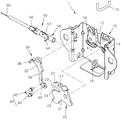
도 2는 본 발명의 일 실시예에 따른 이중 해제용 후드래치의 분해 사시도이다.
도 3은 본 발명의 일 실시예에 따른 견인부의 분해 사시도이다.
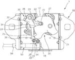
도 4는 본 발명의 일 실시예에 따른 이중 해제용 후드래치의 정면도이다.
도 5는 본 발명의 일 실시예에 따른 이중 해제용 후드래치의 요부구성이 완전잠금위치에 위치된 상태를 개략적으로 도시한 정면도이다.
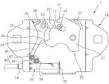
도 6은 본 발명의 일 실시예에 따른 작동케이블의 1차 동작으로 핀부재가 제1지지돌기에 걸려서 파울을 회전시키는 상태를 개략적으로 도시한 정면도이다.
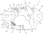
도 7은 본 발명의 일 실시예에 따른 파울이 제3걸림부에 걸려서 스트라이커가 중간잠금위치에 위치된 상태를 개략적으로 도시한 정면도이다.
도 8은 본 발명의 일 실시예에 따른 작동케이블의 2차 동작으로 핀부재가 제2지지돌기에 걸려서 파울을 회전시키는 상태를 개략적으로 도시한 정면도이다.
도 9는 본 발명의 일 실시예에 따른 래치기어가 후드열림위치로 이동되어 스트라이커의 구속이 해제된 상태를 개략적으로 도시한 정면도이다.1 is a perspective view schematically illustrating a double release hood latch according to an embodiment of the present invention.
2 is an exploded perspective view of a double release hood latch according to an embodiment of the present invention.
3 is an exploded perspective view of a traction unit according to an embodiment of the present invention.
4 is a front view of a double release hood latch in accordance with one embodiment of the present invention.
FIG. 5 is a front view schematically showing a state in which the recessed portion of the double release hood latch according to the embodiment of the present invention is located at the fully locked position; FIG.
6 is a front view schematically showing a state in which a pin member is engaged with a first support projection to rotate a foul by a primary operation of an operation cable according to an embodiment of the present invention.
7 is a front view schematically showing a state in which the foul is caught by the third latching portion and the striker is positioned at the intermediate lock position according to the embodiment of the present invention.
8 is a front view schematically showing a state in which a pin member is engaged with a second support projection to rotate the foul by a secondary operation of an operation cable according to an embodiment of the present invention.
9 is a front view schematically showing a state in which the latch gear is moved to the hood opening position and the restraint of the striker is released according to an embodiment of the present invention.
이하 첨부된 도면들을 참조하여 본 발명의 일 실시예에 따른 이중 해제용 후드래치를 설명한다. 설명의 편의를 위해 승용차에 설치된 이중 해제용 후드래치를 예로 들어 설명한다. 이 과정에서 도면에 도시된 선들의 두께나 구성요소의 크기 등은 설명의 명료성과 편의상 과장되게 도시되어 있을 수 있다. Hereinafter, a double release hood latch according to an embodiment of the present invention will be described with reference to the accompanying drawings. For convenience of explanation, a double release hood latch installed in a passenger car is taken as an example. In this process, the thicknesses of the lines and the sizes of the components shown in the drawings may be exaggerated for clarity and convenience of explanation.
또한 후술되는 용어들은 본 발명에서의 기능을 고려하여 정의된 용어들로서, 이는 사용자, 운용자의 의도 또는 관례에 따라 달라질 수 있다. 그러므로 이러한 용어들에 대한 정의는 본 명세서 전반에 걸친 내용을 토대로 내려져야 할 것이다.
Further, the terms described below are defined in consideration of the functions of the present invention, which may vary depending on the intention or custom of the user, the operator. Therefore, definitions of these terms should be made based on the contents throughout this specification.
도 1은 본 발명의 일 실시예에 따른 이중 해제용 후드래치를 개략적으로 도시한 사시도이며, 도 2는 본 발명의 일 실시예에 따른 이중 해제용 후드래치의 분해 사시도이며, 도 3은 본 발명의 일 실시예에 따른 견인부의 분해 사시도이며, 도 4는 본 발명의 일 실시예에 따른 이중 해제용 후드래치의 정면도이며, 도 5는 본 발명의 일 실시예에 따른 이중 해제용 후드래치의 요부구성이 완전잠금위치에 위치된 상태를 개략적으로 도시한 정면도이며, 도 6은 본 발명의 일 실시예에 따른 작동케이블의 1차 동작으로 핀부재가 제1지지돌기에 걸려서 파울을 회전시키는 상태를 개략적으로 도시한 정면도이며, 도 7은 본 발명의 일 실시예에 따른 파울이 제3걸림부에 걸려서 스트라이커가 중간잠금위치에 위치된 상태를 개략적으로 도시한 정면도이며, 도 8은 본 발명의 일 실시예에 따른 작동케이블의 2차 동작으로 핀부재가 제2지지돌기에 걸려서 파울을 회전시키는 상태를 개략적으로 도시한 정면도이며, 도 9는 본 발명의 일 실시예에 따른 래치기어가 후드열림위치로 이동되어 스트라이커의 구속이 해제된 상태를 개략적으로 도시한 정면도이다.FIG. 1 is a perspective view schematically showing a double release hood latch according to an embodiment of the present invention, FIG. 2 is an exploded perspective view of a double release hood latch according to an embodiment of the present invention, FIG. 4 is a front view of a double release hood latch according to an embodiment of the present invention, and FIG. 5 is a front view of the dual release hood latch according to the embodiment of the present invention. 6 is a diagram showing a state in which the pin member is caught by the first support projection and rotates the foul by the primary operation of the operation cable according to the embodiment of the present invention 7 is a front view schematically showing a state in which the striker is positioned at the intermediate lock position when the foul is caught by the third latch portion according to the embodiment of the present invention, Fig. 9 is a front view schematically showing a state in which a pin member is caught by a second support projection and rotates a foul by a secondary operation of an operation cable according to an embodiment of the present invention. Fig. FIG. 3 is a front view schematically showing a state in which the striker is moved to the open position and the restraint of the striker is released; FIG.
도 1 내지 도 4에 도시된 바와 같이, 본 발명의 일 실시예에 따른 이중 해제용 후드래치(1)는, 스트라이커(70)의 이동을 안내하는 이동홈부(12)를 구비하며 차체에 고정되는 베이스(10)와, 베이스(10)에 회전 가능하게 설치되어 이동홈부(12)를 통해 진입된 스트라이커(70)를 구속하며 복수 개의 걸림부를 구비하는 래치기어(20)와, 베이스(10)에 회전 가능하게 설치되며 래치기어(20)에 맞물리는 동작으로 래치기어(20)의 회전을 구속하는 파울(30)과, 파울(30)에서 돌출되는 복수 개의 돌기를 포함하는 돌출부(40)와, 작동케이블(60)과 함께 이동되며 회전되는 동작으로 돌출부(40)에 걸려서 래치기어(20)와 이격되는 방향으로 파울(30)을 회전시키는 견인부(50)를 포함한다.1 to 4, the double
차체에 고정되는 베이스(10)는 스트라이커(70)가 상하(이하 도 2기준)로 이동되기 위한 이동홈부(12)를 형성하는 기술사상 안에서 다양한 형상으로 형성될 수 있다. 일 실시예에 따른 베이스(10)는 판 형상으로 형성되며, 스트라이커(70)의 이동을 안내하는 이동홈부(12)가 상하방향으로 형성된다. 이동홈부(12)의 상측은 개구되어 있으며 하측은 막혀있다.The
베이스(10)의 우측에는 래치기어(20)가 회전 가능하게 설치되며, 베이스(10)의 좌측에는 파울(30)이 회전 가능하게 설치된다. 제1지지축(도시생략)은 래치기어(20)의 래치몸체(21)를 관통하여 베이스(10)의 제1연결공(14)에 삽입되며, 제2지지축(도시생략)은 파울(30)의 파울몸체(32)를 관통하여 베이스(10)의 제2연결공(16)에 삽입된다.A
베이스(10)의 하측에서 전방으로 돌출된 후 다시 상향으로 굽어진 받침편(18)은 반시계 방향으로 회전하는 돌출부(40)에 접한다. 따라서 받침편(18)은 돌출부(40)와 파울(30)이 반시계 방향으로 회전될 때 설정된 각도 이상으로 회전됨을 구속한다.The
래치기어(20)는 베이스(10)에 회전 가능하게 설치되어 이동홈부(12)를 통해 진입된 스트라이커(70)를 구속하며, 복수 개의 걸림부를 구비하는 기술사상 안에서 다양한 형상으로 형성될 수 있다. 일 실시예에 따른 래치기어(20)는 래치몸체(21), 제1걸림부(22), 마운팅홈부(23), 제2걸림부(24), 제3걸림부(25) 및 래치연장편(27)을 포함한다.The
래치몸체(21)는 베이스(10)에 회전 가능하게 설치되며 스트라이커(70)가 삽입되는 마운팅홈부(23)를 구비한다. 일 실시예에 따른 래치몸체(21)는 이동홈부(12)의 우측에 위치하는 베이스(10)에 회전 가능하게 설치된다.The
제1걸림부(22)는 래치몸체(21)에서 돌출되어 마운팅홈부(23)로 삽입되는 스트라이커(70)의 상측에 위치하며, 마운팅홈부(23)로 삽입된 스트라이커(70)의 이탈을 구속하는 기술사상 안에서 다양한 형상으로 변형될 수 있다. 일 실시예에 따른 제1걸림부(22)는 스트라이커(70)를 구속하는 완전잠금위치에서 래치몸체(21)의 수평방향으로 연장된다. 제1걸림부(22)는 완전잠금위치에서 파울(30)을 향하여 연장되며, 이동홈부(12)의 내측에 있는 스트라이커(70)가 이동홈부(12)의 상측으로 이동됨을 구속한다.The
마운팅홈부(23)는 제1걸림부(22)와 제2걸림부(24)의 사이에 위치하며, 베이스(10)의 이동홈부(12)를 통해 상하로 이동하는 스트라이커(70)가 삽입되기 위한 홈부를 형성한다.The
제2걸림부(24)는 스트라이커(70)가 이중 해제용 후드래치(1)에 완전히 잠김 상태로 있는 완전잠금위치에서, 파울(30)에 걸려서 래치기어(20)의 회전이 구속되는 기술사상 안에서 다양한 형상으로 변형될 수 있다.The
일 실시예에 따른 제2걸림부(24)는 마운팅홈부(23)를 사이에 두고 제1걸림부(22)와 이격된 상태로 설치되며, 래치몸체(21)의 측면으로 돌출되어 완전잠금위치에서 파울(30)에 걸린다. 제2걸림부(24)는 이동홈부(12)에 위치하는 스트라이커(70)의 하측에 위치하며, 스트라이커(70)에 밀려서 하측으로 회전될 수 있으며, 스트라이커(70)를 밀면서 상측으로 회전될 수 있다. 즉, 제2걸림부(24)는 래치몸체(21)와 함께 회전되며, 파울(30)의 위치에 따라 파울(30)에 접하여 래치기어(20)의 회전을 구속하거나 파울(30)을 통과하여 반시계 방향 또는 시계 방향으로 회전될 수 있다.The
제3걸림부(25)는 제2걸림부(24)와 단차를 이루며 중간잠금위치에서 파울(30)에 걸리는 기술사상 안에서 다양한 형상으로 형성될 수 있다. 제2걸림부(24)의 일측에는 마운팅홈부(23)가 위치하며, 제2걸림부(24)의 타측은 원호 형상으로 연장된다. 제2걸림부(24)의 타측에 위치하는 제3걸림부(25)는 제2걸림부(24)와 단차를 이루며 래치몸체(21)의 외측으로 돌출되므로, 파울(30)의 걸림돌기(34)는 제2걸림부(24)나 제3걸림부(25)에 걸려서 래치기어(20)의 회전을 구속할 수 있다.The third
래치연장편(27)은 래치몸체(21)에서 돌출되어 제1탄성부재(도시생략)에 연결되는 기술사상 안에서 다양한 형상으로 변형될 수 있다. 일 실시예에 따른 래치연장편(27)은 래치몸체(21)의 상측(이하 도 2기준)으로 연장되어 제1탄성부재의 타측에 연결된다.The
래치기어(20)는, 제1지지축이 관통되는 래치몸체(21)의 회전축을 중심으로 제1걸림부(22), 마운팅홈부(23), 제2걸림부(24) 및 제3걸림부(25)가 반시계 방향을 따라 순차적으로 형성된다.The
파울(30)은 베이스(10)에 회전 가능하게 설치되며, 래치기어(20)에 맞물리는 동작으로 래치기어(20)의 회전을 구속하는 기술사상 안에서 다양한 형상으로 형성될 수 있다. 일 실시예에 따른 파울(30)은, 파울몸체(32), 걸림돌기(34), 연결돌기(36) 및 파울지지편(38)을 포함한다.The foul 30 is rotatably installed on the
파울몸체(32)는 이동홈부(12)를 사이에 두고 래치기어(20)와 대향되는 베이스(10)에 회전 가능하게 연결된다. 일 실시예에 따른 파울몸체(32)는 이동홈부(12)의 좌측에 위치하는 베이스(10)에 회전 가능하게 설치된다.The
걸림돌기(34)는 파울몸체(32)에서 래치기어(20)가 설치된 베이스(10)의 우측을 향하여 돌출되며, 걸림돌기(34)에 래치기어(20)의 제2걸림부(24) 또는 제3걸림부(25)가 걸리므로 래치몸체(21)의 회전이 구속된다. 걸림돌기(34)는 파울몸체(32)에서 돌출되어 래치기어(20)의 회전을 구속하는 기술사상 안에서 다양한 형상으로 형성될 수 있다. 걸림돌기(34)는 래치기어(20)와 마주하는 측면에서 래치기어(20)를 향한 방향으로 돌출되며, 상측에서 하측으로 이동하는 제2걸림부(24)와 제3걸림부(25)에 접촉되어 밀리거나, 하측에서 상측으로 이동하는 제2걸림부(24)나 제3걸림부(25)에 걸려서 래치기어(20)의 회전을 구속한다.The latching
연결돌기(36)는 파울몸체(32)의 하측으로 연장되어 돌출부(40)에 연결되는 기술사상 안에서 다양한 형상으로 형성될 수 있다. 일 실시예에 따른 연결돌기(36)는 파울몸체(32)의 하측에서 베이스(10)의 타측(도 2 기준 우측)을 향하여 연장된다.The connection protrusions 36 may be formed in various shapes within a technical concept that extends to the lower side of the
파울몸체(32)에서 걸림돌기(34)와 연결돌기(36)는 같은 측방향으로 연장되며, 걸림돌기(34)의 하측에 연결돌기(36)가 위치한다.In the
파울몸체(32)에서 돌출된 형상으로 파울지지편(38)이 구비된다. 파울지지편(38)에 제2탄성부재(도시생략)의 일측이 걸리므로 파울몸체(32)를 반시계반향으로 탄성 지지한다.The foul supporting
돌출부(40)는 파울(30)의 연결돌기(36) 전방으로 돌출되는 복수 개의 돌기를 포함하는 기술사상 안에서 다양한 변형이 가능하다. 일 실시예에 따른 돌출부(40)는, 파울(30)의 하측에서 전방을 향하여 돌출되며 작동케이블(60)이 1차로 당겨지는 동작에서 견인부(50)에 걸리는 제1지지돌기(42)와, 제1지지돌기(42)와 이격된 상태로 설치되며 작동케이블(60)이 2차로 당겨지는 동작에서 견인부(50)에 걸리는 제2지지돌기(44)를 포함한다.The
제1지지돌기(42)는 작동케이블(60)이 1차로 당겨지는 동작에서 핀부재(54)에 걸리며, 제2지지돌기(44)는 작동케이블(60)이 2차로 당겨지는 동작에서 핀부재(54)에 걸린다.The
파울(30)의 연결돌기(36)에서 전방으로 돌출된 제1지지돌기(42)와 제2지지돌기(44)는 원형막대 형상으로 형성되므로, 제1지지돌기(42)와 제2지지돌기(44)의 사이로 핀부재(54)의 삽입이 용이하게 이루어진다. 제1지지돌기(42)와 제2지지돌기(44)는 좌우 방향으로 연이어 설치되며, 제1지지돌기(42)와 제2지지돌기(44)의 사이에는 핀부재(54)가 삽입되기 위한 공간이 구비된다.The
견인부(50)는 작동케이블(60)과 함께 이동되며, 회전되는 동작으로 돌출부(40)에 걸려서 래치기어(20)와 이격되는 방향으로 파울(30)을 회전시키는 기술사상 안에서 다양한 종류의 견인장치가 사용될 수 있다. 일 실시예에 따른 견인부(50)는, 작동케이블(60)에 연결되어 길이방향으로 이동되는 이동부재(52)와, 이동부재(52)의 외측으로 돌출되는 핀부재(54)와, 핀부재(54)가 나선형의 홈을 따라 회전하도록 핀부재(54)의 이동을 안내하는 가이드부(56)와, 베이스(10)에 고정되며 작동케이블(60)이 이동되는 공간을 내측에 형성하는 견인몸체(58)를 포함한다.The pulling
이동부재(52)는 작동케이블(60)의 일단에 연결되며 볼 형상으로 형성된다. 따라서 작동케이블(60)의 이동에 따라 이동부재(52)도 같이 이동된다. 핀부재(54)는 핀 형상으로 형성되며 이동부재(52)의 외측에 고정된다. 핀부재(54)는 이동부재(52)와 수직을 이루며 이동부재(52)의 외측으로 돌출된다.The
가이드부(56)는 파이프 형상으로 형성되며, 가이드부(56)의 둘레를 따라 나선형으로 가이드홀(57)이 구비된다. 가이드부(56)는 돌출부(40)의 하측에 위치하며, 가이드부(56)의 일측은 베이스(10)의 지지편(18)에 지지되며, 가이드부(56)의 타측은 견인몸체(58)에 고정된다. 가이드홀(57)은 돌출부(40)와 마주하는 가이드부(56)의 상측에 형성되며, 핀부재(54)는 가이드홀(57)을 통해 가이드부(56)의 외측으로 돌출된다.The
견인몸체(58)도 파이프 형상으로 형성되며, 베이스(10)의 측벽을 관통하는 형상으로 설치된다.The
본 명세서 및 특허청구범위에는, 베이스(10)의 좌측에 파울(30)이 설치되며 베이스(10)의 우측에 래치기어(20)가 설치되며, 래치기어(20)와 핀부재(54)는 시계방향으로 탄성 지지되며, 파울(30)은 반시계 방향으로 탄성 지지되기 위한 탄성력을 공급받고 있음을 예로 들어 설명하였다. 그러나, 베이스(10)의 좌측에 래치기어(20)가 설치되고 베이스(10)의 우측에 파울(30)이 설치되며, 래치기어(20)는 반시계방향으로 탄성 지지되며, 파울(30)은 시계 방향으로 탄성 지지되기 위한 탄성력을 공급받는 후드래치도 본 발명의 다른 실시예라 할 것이다.In this specification and claims, a foul 30 is provided on the left side of the
본 발명의 일 실시예에 따른 이중 해제용 후드래치(1)는, 스트라이커(70)의 구속이 이루어지는 완전잠금위치에서, 파울(30)의 회전에 의해 제2걸림부(24)가 파울(30)의 걸림돌기(34)에서 이격되어 래치기어(20)가 1차 회전하는 1단해제가 이루어진다.The double
1단해제가 이루어진 래치기어(20)는 중간잠금위치에서 정지된다. 그리고 파울(30)의 2차 회전되어 래치기어(20)가 다시 회전하는 2단해제를 통하여 스트라이커(70)의 잠금이 해제되어 후드열림위치에서 후드가 개방된다.The
이하에서는 첨부된 도면들을 참조하여 본 발명의 일 실시예에 따른 이중 해제용 후드래치(1)의 작동상태를 상세히 설명한다.Hereinafter, the operating state of the double
도 5에 도시된 바와 같이, 스트라이커(70)가 제1걸림부(22)와 제2걸림부(24)의 사이에 위치한 상태에서 래치기어(20)의 회전이 구속된 상태를 완전잠금위치로 설정한다. 이때 파울(30)의 걸림돌기(34)에 래치기어(20)의 제2걸림부(24)가 걸린다. 한편 견인부(50)의 핀부재(54)는 돌출부(40)와 이격된 상태이다.The state in which the rotation of the
도 6에 도시된 바와 같이, 작동케이블(60)이 1차 좌측방향으로 당겨지면, 작동케이블(60)에 연결된 이동부재(52)도 좌측으로 당겨지면서 핀부재(54)는 가이드홀(57)을 따라 회전된다. 핀부재(54)는 제1지지돌기(42)와 제2지지돌기(44)의 사이로 삽입되어 제1지지돌기(42)를 이동시킨다. 제1지지돌기(42)의 좌측이동으로, 제1지지돌기(42)에 연결된 파울(30)도 제2지지축이 설치되는 제2연결공(16)을 중심으로 시계방향으로 회전되므로, 걸림돌기(34)가 제2걸림부(24)와 멀어지는 방향으로 이동하는 1단해제가 이루어진다.6, when the operating
도 7에 도시된 바와 같이 파울(30)과 이격된 래치기어(20)가 시계방향으로 회전되어 래치기어(20)의 제3걸림부(25)가 파울(30)의 걸림돌기(34)에 걸리는 중간잠금위치가 된다. 한편 작동케이블(60)을 통하여 전달되는 조작력이 해제되면, 작동케이블(60)과 함께 이동부재(52)는 초기위치로 이동되며, 이동부재(52)에 연결된 핀부재(54)도 가이드홀(57)을 따라 이동되어 돌출부(40)와 이격된다.The
도 8에 도시된 바와 같이, 작동케이블(60)이 다시 좌측방향으로 2차로 당겨지면, 작동케이블(60)에 연결된 이동부재(52)도 좌측으로 당겨지면서 핀부재(54)는 가이드홀(57)을 따라 회전된다. 핀부재(54)는 제2지지돌기(44)의 측면에 접하여 제2지지돌기(44)를 이동시킨다. 제2지지돌기(44)의 좌측이동으로, 제2지지돌기(44)에 연결된 파울(30)도 제2연결공(16)을 중심으로 시계방향으로 회전되므로, 걸림돌기(34)가 제3걸림부(25)와 멀어지는 방향으로 이동하는 2단해제가 이루어진다.8, the
도 9에 도시된 바와 같이, 래치기어(20)는 탄성력에 의해 시계방향으로 회전되어 마운팅홈부(23)가 베이스(10)의 상측에 위치한 공간과 연통되는 후드열림위치를 유지한다. 래치기어(20)의 회전에 연동하여 스트라이커(70)는 마운팅홈부(23)에서 래치기어(20)의 상측으로 이동되므로 스트라이커(70)의 잠금이 해제된다.9, the
한편 작동케이블(60)을 통하여 전달되는 조작력이 해제되면, 작동케이블(60)과 함께 이동부재(52)는 초기위치로 이동되며, 이동부재(52)에 연결된 핀부재(54)도 가이드홀(57)을 따라 이동되어 돌출부(40)와 이격된다.When the operation force transmitted through the
상술한 바와 같이, 본 발명에 따르면 작동케이블(60)의 이동으로 견인부(50)가 동작되어 래치기어(20)의 회전을 구속하는 파울(30)의 회전각도를 제어할 수 있으므로, 자동차의 실내에서 사용자의 조작만으로도 자동차의 후드를 개방시킬 수 있다.As described above, according to the present invention, since the pulling
본 발명은 도면에 도시된 실시예를 참고로 하여 설명되었으나 이는 예시적인 것에 불과하며, 당해 기술이 속하는 분야에서 통상의 지식을 가진 자라면 이로부터 다양한 변형 및 균등한 타 실시예가 가능하다는 점을 이해할 것이다. 또한 승용차에 설치된 이중 해제용 후드래치를 예로 들어 설명하였으나 이는 예시적인 것에 불과하며, 상용차를 포함하여 후드의 개폐가 요구되는 다른 기계장치에도 본 발명에 의한 이중 해제용 후드래치가 적용될 수 있다. 따라서 본 발명의 진정한 기술적 보호범위는 아래의 특허청구범위에 의해서 정하여져야 할 것이다.
While the present invention has been particularly shown and described with reference to exemplary embodiments thereof, it will be understood by those skilled in the art that various changes and modifications may be made without departing from the scope of the invention as defined by the appended claims. will be. In addition, the present invention is not limited to the double release hood latch installed in a passenger car. However, the present invention is merely an example, and the double release hood latch according to the present invention can be applied to other mechanical devices including a commercial vehicle requiring opening and closing of the hood. Accordingly, the true scope of the present invention should be determined by the following claims.
1: 이중 해제용 후드래치
10: 베이스 12: 이동홈부 14: 제1연결공 16: 제2연결공 18: 지지편
20: 래치기어 21: 래치몸체 22: 제1걸림부 23: 마운팅홈부 24: 제2걸림부 25: 제3걸림부 27: 래치연장편
30: 파울 32: 파울몸체 34: 걸림돌기 36: 연결돌기 38: 파울지지편
40: 돌출부 42: 제1지지돌기 44: 제2지지돌기
50: 견인부 52: 이동부재 54: 핀부재 56: 가이드부 57: 가이드홀 58: 견인몸체
60: 작동케이블 70: 스트라이커1: Hood latch for double release
10: base 12: moving groove 14: first connecting hole 16: second connecting hole 18: supporting piece
[0001] The present invention relates to a latch mechanism, and more particularly,
30: fouls 32: foul bodies 34: locking projections 36: connecting projections 38:
40: projecting portion 42: first support projection 44: second support projection
50: pull section 52: moving member 54: pin member 56: guide section 57: guide hole 58: pull body
60: Operation cable 70: Striker
Claims (6)
상기 베이스에 회전 가능하게 설치되어 상기 이동홈부를 통해 진입된 상기 스트라이커를 구속하며, 복수 개의 걸림부를 구비하는 래치기어;
상기 베이스에 회전 가능하게 설치되며, 상기 래치기어에 맞물리는 동작으로 상기 래치기어의 회전을 구속하는 파울;
상기 파울에서 돌출되는 복수 개의 돌기를 포함하는 돌출부; 및
작동케이블과 함께 이동되며, 회전되는 동작으로 상기 돌출부에 걸려서 상기 래치기어와 이격되는 방향으로 상기 파울을 회전시키는 견인부;를 포함하는 것을 특징으로 하는 이중 해제용 후드래치.
A base fixed to the vehicle body and having a moving groove portion for guiding the movement of the striker;
A latch gear rotatably installed on the base, restricting the striker that has entered through the moving groove, and having a plurality of latching portions;
A fulcrum rotatably installed on the base and restraining rotation of the latch gear by engaging with the latch gear;
A protrusion including a plurality of protrusions protruding from the foul; And
And a pulling portion which moves together with the operating cable and rotates the foul in a direction in which the protruding portion is engaged with the protruding portion to be separated from the latch gear.
상기 래치기어는, 상기 베이스에 회전 가능하게 설치되며, 상기 스트라이커가 삽입되는 마운팅홈부를 구비하는 래치몸체;
상기 래치몸체에서 돌출되어 상기 마운팅홈부로 삽입되는 상기 스트라이커의 이탈을 구속하는 제1걸림부;
상기 마운팅홈부를 사이에 두고 상기 제1걸림부와 이격되며, 상기 래치몸체의 측면으로 돌출되어 완전잠금위치에서 상기 파울에 걸리는 제2걸림부; 및
상기 제2걸림부와 단차를 이루며 중간잠금위치에서 상기 파울에 걸리는 제3걸림부;를 포함하는 것을 특징으로 하는 이중 해제용 후드래치.
The method according to claim 1,
The latch gear includes a latch body rotatably mounted on the base and having a mounting groove portion into which the striker is inserted;
A first latching part protruding from the latch body and restricting the release of the striker inserted into the mounting groove;
A second latching portion spaced apart from the first latching portion with the mounting groove portion interposed therebetween, the second latching portion protruding from the side surface of the latch body and engaged with the foul at the fully locked position; And
And a third latching portion that is stepped with the second latching portion and hooked to the foul at an intermediate locking position.
상기 파울은, 상기 이동홈부를 사이에 두고 상기 래치기어와 마주하는 위치에 회전 가능하게 설치되는 파울몸체;
상기 파울몸체에서 돌출되어 상기 제2걸림부 또는 상기 제3걸림부에 걸려서 상기 래치몸체의 회전을 구속하는 걸림돌기; 및
상기 파울몸체의 하측으로 연장되어 상기 돌출부에 연결되는 연결돌기;를 포함하는 것을 특징으로 하는 이중 해제용 후드래치.
3. The method of claim 2,
The foul body being rotatably installed at a position facing the latch gear with the moving groove portion interposed therebetween;
A latching protrusion protruding from the foul body and engaged with the second latching portion or the third latching portion to restrain rotation of the latch body; And
And a connecting protrusion extending downward from the foul body and connected to the protruding portion.
상기 돌출부는, 상기 파울의 하측에서 전방을 향하여 돌출되며, 상기 작동케이블이 1차로 당겨지는 동작에서 상기 견인부에 걸리는 제1지지돌기; 및
상기 제1지지돌기와 이격된 상태로 설치되며, 상기 작동케이블이 2차로 당겨지는 동작에서 상기 견인부에 걸리는 제2지지돌기;를 포함하는 것을 특징으로 하는 이중 해제용 후드래치.
The method according to claim 1,
The protrusion protrudes forward from a lower side of the foul and is engaged with the pulling part in an operation of pulling the operation cable in a first direction; And
And a second support protrusion installed to be spaced from the first support protrusion and engaged with the pulling portion in an operation of pulling the operation cable in a second direction.
상기 견인부는, 상기 작동케이블에 연결되어 길이방향으로 이동되는 이동부재;
상기 이동부재의 외측으로 돌출되는 핀부재;
상기 핀부재가 나선형의 홈을 따라 회전하도록 상기 핀부재의 이동을 안내하는 가이드부; 및
상기 베이스에 고정되며, 상기 작동케이블이 이동되는 공간을 내측에 형성하는 견인몸체;를 포함하는 것을 특징으로 하는 이중 해제용 후드래치.
5. The method according to any one of claims 1 to 4,
The pulling portion includes a moving member connected to the operating cable and moved in the longitudinal direction;
A pin member protruding outside of the moving member;
A guide portion for guiding the movement of the pin member such that the pin member rotates along a spiral groove; And
And a pulling body fixed to the base, the pulling body being formed on an inner side of a space through which the operation cable is moved.
상기 가이드부는 파이프 형상으로 형성되며, 상기 핀부재는 상기 가이드부의 외측으로 돌출되는 것을 특징으로 하는 이중 해제용 후드래치.6. The method of claim 5,
Wherein the guide portion is formed in a pipe shape, and the pin member protrudes to the outside of the guide portion.
Priority Applications (1)
| Application Number | Priority Date | Filing Date | Title |
|---|---|---|---|
| KR1020140135318A KR20160041465A (en) | 2014-10-07 | 2014-10-07 | Hood latch having dual unlocking function |
Applications Claiming Priority (1)
| Application Number | Priority Date | Filing Date | Title |
|---|---|---|---|
| KR1020140135318A KR20160041465A (en) | 2014-10-07 | 2014-10-07 | Hood latch having dual unlocking function |
Publications (1)
| Publication Number | Publication Date |
|---|---|
| KR20160041465A true KR20160041465A (en) | 2016-04-18 |
Family
ID=55916576
Family Applications (1)
| Application Number | Title | Priority Date | Filing Date |
|---|---|---|---|
| KR1020140135318A KR20160041465A (en) | 2014-10-07 | 2014-10-07 | Hood latch having dual unlocking function |
Country Status (1)
| Country | Link |
|---|---|
| KR (1) | KR20160041465A (en) |
Cited By (2)
| Publication number | Priority date | Publication date | Assignee | Title |
|---|---|---|---|---|
| CN109642440A (en) * | 2016-07-06 | 2019-04-16 | 株式会社阿尔发 | Handle device and its manufacturing method |
| CN112412199A (en) * | 2020-11-24 | 2021-02-26 | 江苏金鼎汽车锁制造有限公司 | Face guard lock body for automobile |
-
2014
- 2014-10-07 KR KR1020140135318A patent/KR20160041465A/en not_active Application Discontinuation
Cited By (2)
| Publication number | Priority date | Publication date | Assignee | Title |
|---|---|---|---|---|
| CN109642440A (en) * | 2016-07-06 | 2019-04-16 | 株式会社阿尔发 | Handle device and its manufacturing method |
| CN112412199A (en) * | 2020-11-24 | 2021-02-26 | 江苏金鼎汽车锁制造有限公司 | Face guard lock body for automobile |
Similar Documents
| Publication | Publication Date | Title |
|---|---|---|
| KR101560979B1 (en) | Hood latch having dual unlocking function | |
| US8684425B2 (en) | Vehicle door latch apparatus | |
| JP6178918B2 (en) | Door latch system | |
| KR101662900B1 (en) | Hood latch for vehicle | |
| KR101560969B1 (en) | Hood latch device | |
| KR101643468B1 (en) | Hood latch having dual unlocking function | |
| KR101541251B1 (en) | Hood latch for vehicle | |
| KR101542689B1 (en) | Hood latch device for automobile | |
| KR101603836B1 (en) | Hood latch having dual unlocking function | |
| KR101774525B1 (en) | Hood latch apparatus for automobile | |
| KR101613018B1 (en) | Hood latch for vehicle | |
| KR101573144B1 (en) | Double pull type hood latch | |
| KR20160041465A (en) | Hood latch having dual unlocking function | |
| KR20160034506A (en) | Hood latch having dual unlocking function | |
| KR101662903B1 (en) | Hood latch for automobile | |
| KR101825391B1 (en) | Hood latch apparatus | |
| KR101882745B1 (en) | Hood latch apparatus | |
| KR101585771B1 (en) | Hood latch for automobile | |
| JP6716095B2 (en) | Work vehicle | |
| KR101595332B1 (en) | Hood latch for walker protection | |
| KR101542692B1 (en) | Hood latch for automobile | |
| KR20150124850A (en) | Automobile hood latch for walker protection | |
| KR20160041464A (en) | Automatic release type hood latch | |
| JP6071056B2 (en) | Operation relay device for vehicle door latch | |
| KR102634391B1 (en) | Door ratch assembly of sliding door |
Legal Events
| Date | Code | Title | Description |
|---|---|---|---|
| WITN | Withdrawal due to no request for examination |