KR20160006160A - A system and method for inferring schematic and topological properties of an electrical distribution grid - Google Patents
A system and method for inferring schematic and topological properties of an electrical distribution grid Download PDFInfo
- Publication number
- KR20160006160A KR20160006160A KR1020157025873A KR20157025873A KR20160006160A KR 20160006160 A KR20160006160 A KR 20160006160A KR 1020157025873 A KR1020157025873 A KR 1020157025873A KR 20157025873 A KR20157025873 A KR 20157025873A KR 20160006160 A KR20160006160 A KR 20160006160A
- Authority
- KR
- South Korea
- Prior art keywords
- message
- remote
- remote hub
- data
- grid
- Prior art date
Links
Images


Classifications
-
- H—ELECTRICITY
- H04—ELECTRIC COMMUNICATION TECHNIQUE
- H04B—TRANSMISSION
- H04B3/00—Line transmission systems
- H04B3/54—Systems for transmission via power distribution lines
-
- G—PHYSICS
- G01—MEASURING; TESTING
- G01R—MEASURING ELECTRIC VARIABLES; MEASURING MAGNETIC VARIABLES
- G01R29/00—Arrangements for measuring or indicating electric quantities not covered by groups G01R19/00 - G01R27/00
- G01R29/18—Indicating phase sequence; Indicating synchronism
-
- G—PHYSICS
- G05—CONTROLLING; REGULATING
- G05B—CONTROL OR REGULATING SYSTEMS IN GENERAL; FUNCTIONAL ELEMENTS OF SUCH SYSTEMS; MONITORING OR TESTING ARRANGEMENTS FOR SUCH SYSTEMS OR ELEMENTS
- G05B13/00—Adaptive control systems, i.e. systems automatically adjusting themselves to have a performance which is optimum according to some preassigned criterion
- G05B13/02—Adaptive control systems, i.e. systems automatically adjusting themselves to have a performance which is optimum according to some preassigned criterion electric
-
- H—ELECTRICITY
- H02—GENERATION; CONVERSION OR DISTRIBUTION OF ELECTRIC POWER
- H02J—CIRCUIT ARRANGEMENTS OR SYSTEMS FOR SUPPLYING OR DISTRIBUTING ELECTRIC POWER; SYSTEMS FOR STORING ELECTRIC ENERGY
- H02J13/00—Circuit arrangements for providing remote indication of network conditions, e.g. an instantaneous record of the open or closed condition of each circuitbreaker in the network; Circuit arrangements for providing remote control of switching means in a power distribution network, e.g. switching in and out of current consumers by using a pulse code signal carried by the network
- H02J13/00006—Circuit arrangements for providing remote indication of network conditions, e.g. an instantaneous record of the open or closed condition of each circuitbreaker in the network; Circuit arrangements for providing remote control of switching means in a power distribution network, e.g. switching in and out of current consumers by using a pulse code signal carried by the network characterised by information or instructions transport means between the monitoring, controlling or managing units and monitored, controlled or operated power network element or electrical equipment
- H02J13/00007—Circuit arrangements for providing remote indication of network conditions, e.g. an instantaneous record of the open or closed condition of each circuitbreaker in the network; Circuit arrangements for providing remote control of switching means in a power distribution network, e.g. switching in and out of current consumers by using a pulse code signal carried by the network characterised by information or instructions transport means between the monitoring, controlling or managing units and monitored, controlled or operated power network element or electrical equipment using the power network as support for the transmission
-
- H—ELECTRICITY
- H02—GENERATION; CONVERSION OR DISTRIBUTION OF ELECTRIC POWER
- H02J—CIRCUIT ARRANGEMENTS OR SYSTEMS FOR SUPPLYING OR DISTRIBUTING ELECTRIC POWER; SYSTEMS FOR STORING ELECTRIC ENERGY
- H02J13/00—Circuit arrangements for providing remote indication of network conditions, e.g. an instantaneous record of the open or closed condition of each circuitbreaker in the network; Circuit arrangements for providing remote control of switching means in a power distribution network, e.g. switching in and out of current consumers by using a pulse code signal carried by the network
- H02J13/00032—Systems characterised by the controlled or operated power network elements or equipment, the power network elements or equipment not otherwise provided for
- H02J13/00034—Systems characterised by the controlled or operated power network elements or equipment, the power network elements or equipment not otherwise provided for the elements or equipment being or involving an electric power substation
-
- H—ELECTRICITY
- H04—ELECTRIC COMMUNICATION TECHNIQUE
- H04B—TRANSMISSION
- H04B3/00—Line transmission systems
- H04B3/54—Systems for transmission via power distribution lines
- H04B3/542—Systems for transmission via power distribution lines the information being in digital form
-
- H—ELECTRICITY
- H04—ELECTRIC COMMUNICATION TECHNIQUE
- H04B—TRANSMISSION
- H04B3/00—Line transmission systems
- H04B3/54—Systems for transmission via power distribution lines
- H04B3/546—Combination of signalling, telemetering, protection
-
- H—ELECTRICITY
- H04—ELECTRIC COMMUNICATION TECHNIQUE
- H04L—TRANSMISSION OF DIGITAL INFORMATION, e.g. TELEGRAPHIC COMMUNICATION
- H04L1/00—Arrangements for detecting or preventing errors in the information received
- H04L1/0001—Systems modifying transmission characteristics according to link quality, e.g. power backoff
-
- H—ELECTRICITY
- H04—ELECTRIC COMMUNICATION TECHNIQUE
- H04L—TRANSMISSION OF DIGITAL INFORMATION, e.g. TELEGRAPHIC COMMUNICATION
- H04L41/00—Arrangements for maintenance, administration or management of data switching networks, e.g. of packet switching networks
- H04L41/08—Configuration management of networks or network elements
- H04L41/0803—Configuration setting
- H04L41/0823—Configuration setting characterised by the purposes of a change of settings, e.g. optimising configuration for enhancing reliability
- H04L41/083—Configuration setting characterised by the purposes of a change of settings, e.g. optimising configuration for enhancing reliability for increasing network speed
-
- H—ELECTRICITY
- H04—ELECTRIC COMMUNICATION TECHNIQUE
- H04L—TRANSMISSION OF DIGITAL INFORMATION, e.g. TELEGRAPHIC COMMUNICATION
- H04L41/00—Arrangements for maintenance, administration or management of data switching networks, e.g. of packet switching networks
- H04L41/12—Discovery or management of network topologies
-
- H—ELECTRICITY
- H04—ELECTRIC COMMUNICATION TECHNIQUE
- H04L—TRANSMISSION OF DIGITAL INFORMATION, e.g. TELEGRAPHIC COMMUNICATION
- H04L43/00—Arrangements for monitoring or testing data switching networks
- H04L43/08—Monitoring or testing based on specific metrics, e.g. QoS, energy consumption or environmental parameters
- H04L43/0823—Errors, e.g. transmission errors
- H04L43/0847—Transmission error
-
- G—PHYSICS
- G06—COMPUTING; CALCULATING OR COUNTING
- G06Q—INFORMATION AND COMMUNICATION TECHNOLOGY [ICT] SPECIALLY ADAPTED FOR ADMINISTRATIVE, COMMERCIAL, FINANCIAL, MANAGERIAL OR SUPERVISORY PURPOSES; SYSTEMS OR METHODS SPECIALLY ADAPTED FOR ADMINISTRATIVE, COMMERCIAL, FINANCIAL, MANAGERIAL OR SUPERVISORY PURPOSES, NOT OTHERWISE PROVIDED FOR
- G06Q50/00—Systems or methods specially adapted for specific business sectors, e.g. utilities or tourism
- G06Q50/06—Electricity, gas or water supply
-
- H—ELECTRICITY
- H04—ELECTRIC COMMUNICATION TECHNIQUE
- H04B—TRANSMISSION
- H04B2203/00—Indexing scheme relating to line transmission systems
- H04B2203/54—Aspects of powerline communications not already covered by H04B3/54 and its subgroups
- H04B2203/5429—Applications for powerline communications
- H04B2203/5433—Remote metering
-
- H—ELECTRICITY
- H04—ELECTRIC COMMUNICATION TECHNIQUE
- H04B—TRANSMISSION
- H04B2203/00—Indexing scheme relating to line transmission systems
- H04B2203/54—Aspects of powerline communications not already covered by H04B3/54 and its subgroups
- H04B2203/5462—Systems for power line communications
- H04B2203/5466—Systems for power line communications using three phases conductors
-
- H—ELECTRICITY
- H04—ELECTRIC COMMUNICATION TECHNIQUE
- H04L—TRANSMISSION OF DIGITAL INFORMATION, e.g. TELEGRAPHIC COMMUNICATION
- H04L1/00—Arrangements for detecting or preventing errors in the information received
- H04L1/0001—Systems modifying transmission characteristics according to link quality, e.g. power backoff
- H04L1/0009—Systems modifying transmission characteristics according to link quality, e.g. power backoff by adapting the channel coding
-
- H—ELECTRICITY
- H04—ELECTRIC COMMUNICATION TECHNIQUE
- H04L—TRANSMISSION OF DIGITAL INFORMATION, e.g. TELEGRAPHIC COMMUNICATION
- H04L1/00—Arrangements for detecting or preventing errors in the information received
- H04L1/12—Arrangements for detecting or preventing errors in the information received by using return channel
- H04L1/16—Arrangements for detecting or preventing errors in the information received by using return channel in which the return channel carries supervisory signals, e.g. repetition request signals
- H04L1/18—Automatic repetition systems, e.g. Van Duuren systems
- H04L1/1867—Arrangements specially adapted for the transmitter end
- H04L1/188—Time-out mechanisms
-
- Y—GENERAL TAGGING OF NEW TECHNOLOGICAL DEVELOPMENTS; GENERAL TAGGING OF CROSS-SECTIONAL TECHNOLOGIES SPANNING OVER SEVERAL SECTIONS OF THE IPC; TECHNICAL SUBJECTS COVERED BY FORMER USPC CROSS-REFERENCE ART COLLECTIONS [XRACs] AND DIGESTS
- Y02—TECHNOLOGIES OR APPLICATIONS FOR MITIGATION OR ADAPTATION AGAINST CLIMATE CHANGE
- Y02E—REDUCTION OF GREENHOUSE GAS [GHG] EMISSIONS, RELATED TO ENERGY GENERATION, TRANSMISSION OR DISTRIBUTION
- Y02E60/00—Enabling technologies; Technologies with a potential or indirect contribution to GHG emissions mitigation
-
- Y—GENERAL TAGGING OF NEW TECHNOLOGICAL DEVELOPMENTS; GENERAL TAGGING OF CROSS-SECTIONAL TECHNOLOGIES SPANNING OVER SEVERAL SECTIONS OF THE IPC; TECHNICAL SUBJECTS COVERED BY FORMER USPC CROSS-REFERENCE ART COLLECTIONS [XRACs] AND DIGESTS
- Y04—INFORMATION OR COMMUNICATION TECHNOLOGIES HAVING AN IMPACT ON OTHER TECHNOLOGY AREAS
- Y04S—SYSTEMS INTEGRATING TECHNOLOGIES RELATED TO POWER NETWORK OPERATION, COMMUNICATION OR INFORMATION TECHNOLOGIES FOR IMPROVING THE ELECTRICAL POWER GENERATION, TRANSMISSION, DISTRIBUTION, MANAGEMENT OR USAGE, i.e. SMART GRIDS
- Y04S10/00—Systems supporting electrical power generation, transmission or distribution
- Y04S10/16—Electric power substations
-
- Y—GENERAL TAGGING OF NEW TECHNOLOGICAL DEVELOPMENTS; GENERAL TAGGING OF CROSS-SECTIONAL TECHNOLOGIES SPANNING OVER SEVERAL SECTIONS OF THE IPC; TECHNICAL SUBJECTS COVERED BY FORMER USPC CROSS-REFERENCE ART COLLECTIONS [XRACs] AND DIGESTS
- Y04—INFORMATION OR COMMUNICATION TECHNOLOGIES HAVING AN IMPACT ON OTHER TECHNOLOGY AREAS
- Y04S—SYSTEMS INTEGRATING TECHNOLOGIES RELATED TO POWER NETWORK OPERATION, COMMUNICATION OR INFORMATION TECHNOLOGIES FOR IMPROVING THE ELECTRICAL POWER GENERATION, TRANSMISSION, DISTRIBUTION, MANAGEMENT OR USAGE, i.e. SMART GRIDS
- Y04S40/00—Systems for electrical power generation, transmission, distribution or end-user application management characterised by the use of communication or information technologies, or communication or information technology specific aspects supporting them
- Y04S40/12—Systems for electrical power generation, transmission, distribution or end-user application management characterised by the use of communication or information technologies, or communication or information technology specific aspects supporting them characterised by data transport means between the monitoring, controlling or managing units and monitored, controlled or operated electrical equipment
- Y04S40/121—Systems for electrical power generation, transmission, distribution or end-user application management characterised by the use of communication or information technologies, or communication or information technology specific aspects supporting them characterised by data transport means between the monitoring, controlling or managing units and monitored, controlled or operated electrical equipment using the power network as support for the transmission
Abstract
배전 그리드의 도식적 및 위상학적 특성을 유추하기 위한 시스템 및 방법이 제공된다. 이 시스템은, 원격 허브, 종속 원격장치, 서브스테이션 수신기, 및 연관된 컴퓨팅 플랫폼과 집중화기를 포함할 수 있다. 원격 허브 엣지 전송기라 불리는 적어도 하나의 지능형 엣지 전송기는 전기 계측기에 공급하는 전력 메인 내에 변조된 전류를 주입함으로써 배전 그리드 상에서 메시지를 전송할 수 있다. 종속 원격장치, 원격 허브, 서브스테이션 수신기, 및 연관된 컴퓨팅 플랫폼과 집중화기는, 네트워크 내의 각 노드가 온-그리드 네트워크를 구성하고 네트워크 상에서 메시지를 송수신하기 위한 방법을 구현하는 것을 허용하는 저장된 명령어들을 실행하는 처리 유닛을 포함할 수 있다. 서브스테이션 수신기, 컴퓨팅 플랫폼 및 집중화기는 네트워크의 도식적 그리드 위치 속성을 검출 및 유추하고 검출 및 유추된 속성을 논리적 및 물리적 네트워크 모델을 유지하는 지리공간적 정보 시스템을 포함한 다른 애플리케이션 시스템에 퍼블리싱할 수 있다.A system and method are provided for inferring the schematic and topological characteristics of a distribution grid. The system may include a remote hub, a slave remote device, a sub-station receiver, and an associated computing platform and centralizer. At least one intelligent edge transmitter, referred to as a remote hub edge transmitter, can transmit messages on the distribution grid by injecting a modulated current into the power main that supplies the electrical meter. The subordinate remote device, the remote hub, the sub-station receiver, and the associated computing platform and centralizer execute the stored instructions that allow each node in the network to configure the on-grid network and implement methods for sending and receiving messages on the network Processing unit. The sub-station receivers, computing platforms, and concentrators can detect and infer the graphical grid location attributes of the network and publish detected and other attributes to other application systems, including geospatial information systems that maintain logical and physical network models.
Description
관련 출원Related application
본 출원은, 참조에 의해 그 내용이 본 명세서에 포함되는 2013년 2월 19일 출원된 미국 가출원 제61/766,551호와 2013년 3월 13일 출원된 미국 가출원 제61/779,222호의 우선권 혜택을 주장한다.This application claims priority benefit from U.S. Provisional Application No. 61 / 766,551, filed February 19, 2013, the contents of which are incorporated herein by reference and U.S. Provisional Application No. 61 / 779,222, filed March 13, do.
발명의 분야Field of invention
본 발명은 단거리 및 장거리 전송 매체 및 데이터-베어링 네트워크(data-bearing network)로서 배전 그리드(electrical distribution grid)를 채용하는 것에 관한 것으로, 또한, 시간에 따라 변하는 배전 그리드의 도식적 및 위상학적 특성을 유추하기 위한 목적의 네트워크 상의 신호와 메시지의 이용에 관한 것이다.The present invention relates to employing an electrical distribution grid as a short-haul and long-haul transmission medium and a data-bearing network and also relates to the schematic and topological characteristics of a time- And to the use of signals and messages on the network for the purpose.
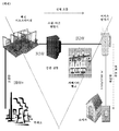
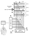
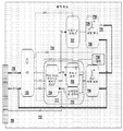
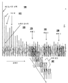
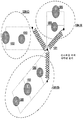
전력 그리드는, 일반적으로 2개의 논리적 영역, 전송 그리드(들)와 배전 그리드(들)로 구성된 것으로 간주된다. 전송 그리드는, 수력발전 댐, 원자로, 풍력 발전, 및 석탄 화력이나 가스 화력 발전소 등의 대규모 발전 지점들에서 시작한다. 발전 지점으로부터의 전력은, 긴 고전압 라인의 느슨하게 접속된 네트워크(loosely connected network)를 통해 공장, 농장, 및 인구밀집 중심지 등의 전력 수요가 존재하는 지점까지 고전압 교류(AC)로서 전송된다. 전송 그리드의 엣지들(edges of the Transmission Grid)에는 한 집단의 배전 서브스테이션(collection of Distribution Substations)이 존재한다. 배전 서브스테이션은, 고 전송 라인 레벨(통상 130 kV 내지 700 kV)로부터 배전 서비스 영역(distribution service area) 내의 소비자들에게 전력이 분배되는 중간 전압 레벨(통상 4kV 내지 약 35 kV)로 전압을 감압(step down)하는 하나 이상의 서브스테이션 변압기(Substation Transformer)를 포함한다. 배전 그리드의 엣지에는, 배전 그리드의 중간 전압을 저전압(미국에서는 통상 120V, 208V, 240V, 277V, 또는 480V)으로 변환하는 다수의 서비스 변압기(Service Transformer)가 있다. 이 세상의 다른 곳에서는 이들 중 일부 외에도 다른 전압들이 이용될 수 있다. 일부 경우에, 스텝-다운 변압기(step-down transformer)라 불리며, 개괄적으로 서브스테이션 변압기와 서비스 변압기 사이에 놓이는 하나 이상의 변압기들의 계층(a tier of one or more transformers)은 서브스테이션 및 서비스 변압기 사이에서 중간 전압 감축을 생성한다. 각각의 서비스 변압기는 하나 이상의 계량된 부하(metered load)에 전력을 공급한다. 부하는, 주거지, 상업용 또는 산업용 건물, 일련의 가로등과 같은 도시 인프라스트럭쳐 요소, 또는 관개 시스템과 같은 농업 장치일 수 있다. 전형적인 배전 그리드는 전력의 흐름을 밸런싱하고 통제하는데 이용되는 기타의 요소를 포함한다. 이러한 요소들의 예로서는, 커패시터 뱅크(capacitor bank), 전압 조정기(voltage regulator), 스위치, 및 재폐로차단기(recloser)가 있다. 도 1은 전력 그리드의 전형적인 세그먼트(segment)를 나타낸다.The power grid is generally considered to consist of two logical areas, the transmission grid (s) and the distribution grid (s). Transmission grids begin with large-scale power generation dams, hydropower dams, reactors, wind power, and coal-fired or gas-fired power plants. Power from the power generation point is transmitted as a high voltage alternating current (AC) through a loosely connected network of long high voltage lines to the point where power needs such as factories, farms, and population centers are present. There are a collection of Distribution Substations in the edges of the Transmission Grid. The distribution substation reduces the voltage to an intermediate voltage level (typically 4 kV to about 35 kV) at which power is distributed to consumers within the distribution service area from the high transmission line level (typically 130 kV to 700 kV) step down) the substation transformer. At the edge of the distribution grid there are a number of service transformers that convert the intermediate voltage of the distribution grid to low voltages (typically 120V, 208V, 240V, 277V, or 480V in the US). Other voltages may be used elsewhere in the world besides some of them. In some cases, a tier of one or more transformers, generally referred to as a step-down transformer, lying between the substation transformer and the service transformer, is located between the substation and the service transformer Thereby generating a medium voltage reduction. Each service transformer provides power to one or more metered loads. The load may be a residential, commercial or industrial building, an urban infrastructure element such as a series of streetlamps, or an agricultural device such as an irrigation system. Typical distribution grids include other elements used to balance and control the flow of power. Examples of such elements are a capacitor bank, a voltage regulator, a switch, and a recloser. Figure 1 shows a typical segment of a power grid.
배전 그리드는 다양한 위상학적 구성으로 설계되고 배치되었다. 미국에서, 배전 그리드 유형들은 통상적으로, 방사형, 루프, 또는 네트워킹형을 특징으로 한다. 다른 부상하는 경우는 캠퍼스 그리드(campus grid) 및 마이크로그리드(microgrid)이다. 세상의 다른 곳에서는 설명되지 않은 추가의 토폴로지가 이용된다.Distribution grids are designed and arranged in various topological configurations. In the United States, distribution grid types are typically characterized by a radial, loop, or networking type. Other injuries are the campus grid and the microgrid. Additional topologies that are not described elsewhere in the world are used.
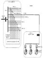
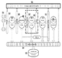
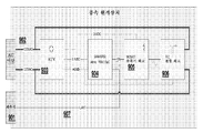
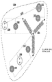
도 2a는 전형적인 방사형 그리드의 위상학적 개략도이다. 방사형 그리드에서, 서브스테이션은 하나 이상의 서브스테이션 변압기를 가진다. 각각의 서브스테이션 변압기는 하나 이상의 서브스테이션 버스를 가진다. 하나 이상의 3-페이즈 피더(three-phase feeder)는 각각의 서브스테이션 버스로부터 바깥쪽으로 "방사"하고, 단일-페이즈, 듀얼-페이즈, 또는 3-페이즈 래터럴 라인들(lateral lines)이 피더로부터 분기하고, 차례로 탭-오프 지점(또는 간단히 "탭")이 래터럴(lateral)로부터 분기한다. 방사형 그리드는 간단하므로 설계 및 구축하기에 저렴하지만, 리던던트 전력 경로가 없어서 정전에 가장 취약하므로 임의의 고장은 적어도 하나의 부하가 전력을 소실하게 한다.Figure 2a is a topological schematic view of a typical radial grid. In a radial grid, a substation has one or more substation transformers. Each substation transformer has one or more substation buses. One or more three-phase feeders may "radiate" outwardly from each sub-station bus, and single-phase, dual-phase, or 3-phase lateral lines may diverge from the feeder , And in turn a tap-off point (or simply "tab") branches off from the lateral. Radial grids are simple to design and build, but they are the most vulnerable to outages because there is no redundant power path, so any failure causes at least one load to lose power.
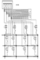
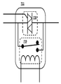
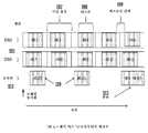
도 2b는 전형적인 루프 배전 그리드의 위상학적 개략도이다. 루프 그리드에서, 선택 피더의 각 단은 서브스테이션 변압기의 버스 등의 전원에 부착된다. 루프가 손상되지 않으면, 어느 한 서브스테이션 변압기가 동작하는 경우 모든 부하에서 전력이 이용가능하다. 루프 내에 고장이 있다면, 양쪽 변압기가 동작한다고 가정할 때 모든 부하에서 전력이 이용가능하다. 보통의 상황에서, 한 번에 단 하나의 서브스테이션 변압기가 그리드의 각 세그먼트에 전력을 전달하고 있다는 것을 보장하기 위해 스위치 시스템이 이용된다.2B is a topological schematic view of a typical loop distribution grid. In the loop grid, each end of the optional feeder is attached to a power source such as a bus of a substation transformer. If the loop is undamaged, power is available at all loads when either substation transformer is operating. If there is a fault in the loop, power is available at all loads assuming both transformers are operating. In normal circumstances, a switch system is used to ensure that only one substation transformer at a time is transmitting power to each segment of the grid.
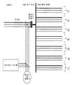
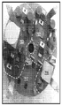
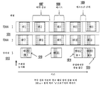
도 2c는 전형적인 네트워킹형 그리드의 위상학적 개략도이다. 이 토폴로지는 최대의 리던던시를 가진다. 복수의 전원을 채용하는 것 외에도, 모든 서비스 변압기들은 메시 구조의 2차측(secondary side) 상에서 서로 링크된다. 임의의 지점에서의 정전을 야기하기 위해서는 복수의 접속 단절이 요구된다. 네트워킹형 그리드는 구축 및 유지하기에 가장 값비싸고, 통상적으로는 고-가치 및 고-임계성 부하들이 함께 집중되어 있는 맨하탄 또는 워싱턴 DC 등의 주요 도시 지역에서 이용된다.Figure 2C is a topological schematic of a typical networked grid. This topology has maximum redundancy. In addition to employing multiple power sources, all service transformers are linked together on the secondary side of the mesh structure. In order to cause a power failure at an arbitrary point, a plurality of connection disconnection is required. Networked grids are the most expensive to build and maintain and are typically used in major urban areas such as Manhattan or Washington DC where high-value and high-critical loads are concentrated together.
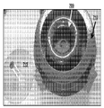
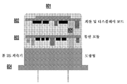
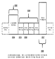
도 2d는 마이크로그리드 또는 캠퍼스 네트워크를 도시한다. 마이크로그리드는 배전 기술에서 전통적인 것은 아니지만, 에너지 절약 및 재생 에너지원으로부터의 에너지의 분산된 생성에 관한 증가하는 집중에 대한 응답으로서 부상하고 있다. 많은 변형이 가능하다. 이러한 유형의 그리드는 통상적으로는 더 넓은 배전 그리드에 부착되지만 이로부터 분리가능하고, 풍차, 태양전지 패널, 또는 충전가능한 스토리지 배터리 등의 그 자신의 전원 뿐만 아니라 부하도 포함할 수 있다. 전체의 네트워크는 저전압 라인을 채용할 수 있다.Figure 2D illustrates a microgrid or campus network. Microgrid is not traditional in distribution technology, but it is emerging as an answer to the growing concentration of energy-saving and distributed generation of energy from renewable energy sources. Many variations are possible. This type of grid is typically attached to, but detachable from, a larger distribution grid and may include loads as well as its own power sources such as windmills, solar panels, or rechargeable storage batteries. The entire network can employ low voltage lines.
배전 서브스테이션은 전송 그리드로부터 하나 이상의 큰 전력 변압기 내로 고전압 전력을 수신한다. 배전 변압기는, 변압기의 2차 권선 회로의 일부 권선을 포함하거나 배제함으로써 입력 대 출력 전압비를 변경해 변압기가 배전 버스(power distribution bus)(서브스테이션 버스)에 전달하는 전압을 변경하는, 부하-탭 변경기(load-tap changer)라 불리는 한 유형의 조정기를 포함할 수 있다. 하나 이상의 피더는 서브스테이션 버스에 의존한다. 너무 많은 피더들이 요구된다면, 추가의 변압기들과 버스들이 이용된다.The distribution substation receives high voltage power from the transmission grid into one or more large power transformers. The distribution transformer is a load-tap change that changes the input-to-output voltage ratio by including or excluding some windings of the secondary winding circuit of the transformer to change the voltage that the transformer delivers to the power distribution bus (substation bus) And a type of regulator called a load-tap changer. One or more feeders are dependent on the substation bus. If too many feeders are required, additional transformers and busses are used.
그리드의 컴포넌트들을 모니터링 및 제어하기 위하여, 전류 변압기(CT; current transformer) 또는 홀-효과 센서(Hall-effect sensor) 등의 기타의 전류 센서가 서브스테이션 내의 전력-베어링 도체에 부착된다. CT는 루핑된 도체 상에 낮은 전류를 출력하고, 이것은 모니터링 중인 고전압 도체에서 전달된 전류에 정확히 비례한다. 이들 저전류 출력은, 서브스테이션 내의 SCADA(Supervisory Control and Data Acquisition) 시스템과 연관된 데이터 취득 서브시스템에 접속하는데 적합하다. 1차 모니터링 CT들은, 전류가 흐르는 동안 고전압 컴포넌트들에 CT를 추가하거나 변경하는 것은 불가능하거나 위험하기 때문에, 서브스테이션 내에 설계 및 구축된다. 반면, 필요하다면 추가의 CT들이 전력 전달에 영향을 주지 않고 저전류 SCADA 루프에 안전하게 부가될 수 있다.In order to monitor and control the components of the grid, other current sensors, such as current transformers (CT) or Hall-effect sensors, are attached to the power-bearing conductors in the substations. CT outputs a low current on the roofed conductor, which is exactly proportional to the current delivered by the high-voltage conductor being monitored. These low current outputs are suitable for connection to a data acquisition subsystem associated with a Supervisory Control and Data Acquisition (SCADA) system within a substation. Primary monitoring CTs are designed and built in sub-stations because it is impossible or dangerous to add or change CTs to high voltage components while current is flowing. On the other hand, additional CTs can be safely added to the low current SCADA loop without affecting power delivery if necessary.
전력선 그 자체 외에도, 배전 그리드는, 전력의 흐름을 통제, 분리, 안정화, 및 방향전환(divert)시키는 수 많은 다른 장치들을 포함한다. 이들 장치들로는, 스위치, 재폐로차단기, (대개 역률 보정(power factor correction)을 위한) 커패시터 뱅크, 및 2차 전압 조정기가 포함된다. 이들 장치들 모두는, 그리드 상의 다양한 부하들과 2차 전원들이 그러하듯이, 데이터-베어링 네트워크로서 간주될 때 배전 그리드의 거동에 영향을 준다. 부하들이 턴 온 및 오프될 수 있는 바와 같이 갑작스런 상태 변화를 갖는 장치들은 그리드에 임펄스 노이즈를 도입할 것이다. 변압기 및 커패시터 뱅크 등의 일부 장치는 소정의 주파수의 신호를 필터링 및 감쇠시킨다.In addition to the power line itself, the power distribution grid includes a number of other devices that control, isolate, stabilize, and divert the flow of power. These devices include a switch, a recloser, a capacitor bank (usually for power factor correction), and a secondary voltage regulator. All of these devices affect the behavior of the distribution grid when viewed as a data-bearing network, as are the various loads on the grid and secondary sources. Devices with sudden state changes, as loads can be turned on and off, will introduce impulse noise into the grid. Some devices, such as transformers and capacitor banks, filter and attenuate signals at a given frequency.
소비자 부하 및 연관된 계측기를 서비스 변압기에 접속하는 와이어 외에, 서비스 변압기는 전력이 실제로 소비자에게 전달되기 이전의 배전 그리드의 최외곽 요소이다. 계측기는 서비스 변압기로부터의 전력이 소비자에게 전달되는 지점에 부착된다. 서비스 변압기는, 계측기처럼, 3-페이즈, 듀얼-페이즈, 또는 단일-페이즈일 수 있다.In addition to connecting the consumer load and the associated instrument to the service transformer, the service transformer is the outermost element of the distribution grid before power is actually delivered to the consumer. The instrument is attached to the point where power from the service transformer is delivered to the consumer. The service transformer may be a three-phase, dual-phase, or single-phase, such as a meter.
전통적으로, 계측기 판독은 전기 유틸리티에 의해 초래되는 가장 큰 동작 비용 중 하나이다. 원래의 전기 계측기는, 유틸리티 요금청구 프로세스를 진행하기 위해 월별로 수동으로 검사되어야 했던 광학적 판독을 갖춘 아날로그 장치였다. 1970년대 초기에, 계측기 데이터를 디지털화하고 그 수집을 자동화하기 위한 메커니즘들이 배치되기 시작했다. 이들 메커니즘들은, 계측기가 그 전류 판독치를 단거리 무선 신호를 이용하여 브로드캐스팅하고 계측기 판독자가 소지한 장치에 의해 수신되는 도보식(walk-by) 또는 차량식(drive-by) 시스템으로부터 진화되었다. 이들 초기 시스템은 자동화된 계측기 판독 시스템 또는 AMR이라 알려져 있다. 나중에, 집계된 판독치를 운송하기 위한 광대역 백홀 수단이 장착된 수집 지점과 메시 구성의 단거리 RF 리피터의 조합을 채용한 각종의 특별한 목적을 위해 만들어진 데이터 수집 네트워크가 배치되기 시작했다.Traditionally, instrument readings are one of the largest operating costs incurred by electrical utilities. The original electrical instrument was an analog device with optical readings that had to be manually checked monthly to proceed with the utility billing process. In the early 1970s, mechanisms for digitizing instrument data and automating its collection began to be deployed. These mechanisms evolved from a walk-by or drive-by system in which the instrument broadcasts its current reading using a short-range radio signal and is received by a device carried by the instrument reader. These initial systems are known as automated instrument readout systems or AMRs. Later, a data collection network was created for various special purposes that employed a combination of a collection point equipped with broadband backhaul means for transporting aggregated readings and a short range RF repeater in mesh configuration.
이들 네트워크들은, 유틸리티 서비스 센터의 "계측 헤드엔드(metering head-end)"와, 일반적으로 AMI(Advanced Metering Infrastructure)라 불리는 이 데이터 수집 네트워크의 엣지에 있는 계측기 사이의 양방향 통신이 가능했다. AMI들은 빈번하게, 전형적으로는 매 15분마다 판독치를 수집 및 저장할 수 있고, 이를 거의 그 정도로 빈번하게 보고할 수 있다. 이들은 이 피쳐가 드물게 사용된다고 가정하여 요구시에 임의의 계측기를 판독할 수 있고, 또한 요구시에 임의의 계측기를 접속 또는 분리할 수 있다. AMI 계측기는, 에너지 절약, 수요 관리, 및 가변율 요금청구(variable-rate billing)의 목적을 위해 신호를 소비자 장치에 전달할 수 있다. AMI 네트워크는 배전 그리드와는 분리되어 있기 때문에, AMI 계측기는 그리드 토폴로지의 변화 또는 그리드 상의 소정의 상태를 모르며 이에 대해 민감하지도 않다. 그럼에도 불구하고, AMI의 도입은 일반적으로 스마트 그리드(Smart Grid)의 시작인 것으로 간주된다.These networks enabled bi-directional communication between a "metering head-end" of a utility service center and an instrument on the edge of this data acquisition network, commonly referred to as the Advanced Metering Infrastructure (AMI). AMIs can collect and store readings frequently, typically every 15 minutes, and report them almost as often and frequently. They can read any instrument on demand, assuming this feature is used infrequently, and can also connect or disconnect any instrument on demand. The AMI instrument can deliver signals to the consumer device for energy saving, demand management, and variable-rate billing purposes. Because the AMI network is separate from the distribution grid, the AMI instrument does not know and is not sensitive to changes in the grid topology or certain states on the grid. Nonetheless, the introduction of AMI is generally considered to be the beginning of a Smart Grid.
배전 인프라스트럭쳐의 많은 특성들은 그리드 자체를 통신 매체로서 이용하려는 노력의 성공을 제한해 왔다. 먼저, 그리드는 노이즈있는 환경이다. 이미 언급한 바와 같이, 그리드 상의 부하의 상태 변화 뿐만 아니라 그리드 자체의 제어 및 통제 아티팩트는 전력선 상에 임펄스 노이즈를 야기한다. 전기 모터와 같은 부하의 보통의 동작, 전체 부하에서의 단순한 변동, 및 (주로 번개 및 기타의 기상-관련 이유로부터의) 주변 RF 노이즈는 상당한 가우시안(Gaussian) 노이즈를 추가한다. 미국의 전형적인 서브스테이션에서의 측정된 노이즈 플로어(noise floor)는 60 Hz 기본(fundamental)의 최대 진폭의 약 80-90dB 아래에 있다. 그리드의 복소 임피던스는 주파수와 시간 영역 모두에서 변한다. 이것은, 임피던스가 증가할 때 그리드 상의 더 높은 전압 지점에 놓인 수신기에서의 신호 손실로 이어질 수 있거나, 대안적으로, 전송기가 평균적으로 필요한 에너지보다 많은 에너지를 이용하게 강제한다. 역률을 최적화하기 위한 목적으로 그리드를 따른 지점들에 놓인 커패시터 뱅크들은 신호 감쇠를 야기할 수 있다. 가장 중요하게는, 변압기는 저역-통과 필터처럼 작용하여, 소정 주파수 위의 신호를 극적으로 감쇠시킨다. 임계 주파수는 모든 배전 그리드 상에서 동일하지 않은데, 그 이유는, 상이한 구조와 유형의 변압기들이 채용되며 변압기 자체는 지정된 주파수에서 필터링하도록 의도적으로 튜닝되지 않기 때문이다. 이들 모든 변수들은 매체의 주파수 응답에 영향을 준다.Many characteristics of the distribution infrastructure have limited the success of efforts to use the grid itself as a communication medium. First, the grid is a noisy environment. As already mentioned, control and control artifacts of the grid itself as well as changes in the state of the load on the grid cause impulse noise on the power line. Normal operation of loads such as electric motors, simple fluctuations at full load, and ambient RF noise (mainly from lightning and other weather-related reasons) adds significant Gaussian noise. The measured noise floor at a typical US substation is below about 80-90 dB below the maximum amplitude of a 60 Hz fundamental. The complex impedance of the grid varies in both frequency and time domain. This may lead to signal loss at the receiver at a higher voltage point on the grid as the impedance increases or alternatively forces the transmitter to use more energy than the average required energy. For the purpose of optimizing the power factor, capacitor banks placed at points along the grid may cause signal attenuation. Most importantly, the transformer acts like a low-pass filter to dramatically attenuate signals above a certain frequency. The critical frequency is not the same across all distribution grids because different structures and types of transformers are employed and the transformer itself is not intentionally tuned to filter at a specified frequency. All these parameters affect the frequency response of the medium.
추가로, 그리드 상에 변조된 전류 신호를 주입하는 것은 주입된 신호들 자체간에 간섭을 야기할 수 있다. 한 문제가 되는 현상은, 하나의 전력선 상에 주입된 신호가 또 다른 라인 상에서 검출될 수 있는 크로스토크(crosstalk)이다. 동일한 피더의 2개 이상의 페이즈 상에서 크로스토크가 발생할 때, 이것은 페이즈 라인들이 피더의 대부분의 길이에 대해 서로 나란히 이어질 때 유도성 및 용량성 결합에 의해 야기될 수 있다. 크로스토크는 또한 동일한 변압기 코어 상의 복수의 페이즈 권선으로 인해 야기될 수도 있다. 피더-대-피더 크로스토크(feeder-to-feeder crosstalk)도 역시 측정되었고, 서브스테이션에서의 전력 버스로부터의 주입된 신호의 반사에 의해 야기될 수 있다. 미국 및 세계에서의 배전 그리드의 복잡성, 다양성, 및 경년(age)을 감안하면, 이들 현상에 대해 예상보다 덜 알려져 있다.In addition, injecting a modulated current signal on the grid can cause interference between the injected signals themselves. One problem is the crosstalk, in which the signal injected on one power line can be detected on another line. When crosstalk occurs over two or more phases of the same feeder, this can be caused by inductive and capacitive coupling when the phases line up next to one another for most of the length of the feeder. Crosstalk may also be caused by multiple phase windings on the same transformer core. A feeder-to-feeder crosstalk has also been measured and can be caused by the reflection of the injected signal from the power bus at the substation. Given the complexity, diversity, and age of distribution grids in the United States and the world, these phenomena are less well known than anticipated.
결국, 통신 매체로서 배전 그리드를 이용하는 것은, 당연히 깨끗하고, 신뢰성있는 전력을 소비자에게 전달하는 것인, 그리드의 주된 목적을 간섭하는 부작용을 종종 가진다. 전력 하에서의 장치가 주입된 전류와 공진한다면, 깜빡임(flicker)이라는 현상이 생긴다. LED, CFL, 백열 및 형광등은 소정의 주파수에 응답하여 가시적으로 깜빡거린다. 시각적 깜빡임은 발작과 현기증 모두를 야기하는 것으로 증명되었기 때문에, 이것은 짜증스러우며 때때로 위험하다. 팬 및 스피커 등의 다른 유형의 장치들도 역시 소정 주파수에서 공진하여, 가청의 웅웅거림(hum)을 야기한다. ANSI/IEEE 표준 519는, 깜빡임 발생을 피하기 위해 소정 주파수와 진폭에서 이렇게 하는 것을 피하도록 그리드 상에 전류를 주입하는 (통신 장치로서 의도된 것이든 아니든) 임의의 장치를 요구한다. 구체적으로는, ANSI/IEEE 표준 519는 제11 고조파의 또는 그 아래의 기본(fundamental)의 홀수 고조파에 어떠한 노이즈도 추가되지 않을 것을 요구한다.Ultimately, using distribution grids as communication media often has the side effect of interfering with the primary purpose of the grid, of course, delivering clean, reliable power to consumers. If the device under power resonates with the injected current, there is a phenomenon called flicker. LEDs, CFLs, incandescent lamps and fluorescent lamps visibly flicker in response to a predetermined frequency. This is annoying and sometimes dangerous because visual flicker has been proven to cause both seizures and dizziness. Other types of devices, such as fans and speakers, also resonate at a given frequency, resulting in audible hum. The ANSI / IEEE standard 519 requires any device (whether intended as a communication device or not) to inject current on the grid to avoid doing so at a certain frequency and amplitude to avoid flicker. Specifically, the ANSI / IEEE standard 519 requires that no noise be added to fundamental odd harmonics of or below the eleventh harmonic.
전력 그리드를 통신 매체로서 이용하는데 있어서 고유한 많은 공학적 곤란점들에도 불구하고, 이것은, 유틸리티가 이미 인프라스트럭쳐를 소유하고, 유틸리티가 데이터를 수집할 필요가 있는 모든 지점들에 존재하기 때문에 전기 유틸리티에 대해 매력적으로 남아 있다. 또한, POU(publicly owned utility)의 규제 및 비용 구조는 전화 또는 케이블 제공자 등의 제3자 통신 제공자에게 운영 비용을 지불하는 것과는 반대로 (서비스율(service rate) 증가를 통해 이익이 되게 구입 및 유지될 수 있는) 소유 자산을 이용하는 것들을 강하게 선호한다.Despite the many engineering difficulties inherent in using the power grid as a communications medium, this is because the utility already owns the infrastructure and is present at every point where the utility needs to collect data, It remains attractive for. In addition, regulatory and cost structures of POUs (publicly owned utility) can be purchased and maintained profitably through increased service rates (as opposed to paying operating costs to third party telecommunications providers such as telephone or cable providers) (Which can be used).
(1MHz 초과의) 고주파 전송은 이론적으로 높은 데이터 레이트가 달성될 수 있기 때문에 매력적이다. BPL(Broadband over Power Line)이라 불리는 이러한 방식은 소비자들에게 그들의 전기 계측기에 위치한 게이트웨이를 통해 인터넷 액세스를 전달하기에 충분한 잠재적인 이론적 대역폭을 제공한다. 21세기 초에, 미국의 연방 통신 위원회(FCC; Federal Communications Commission)는, 지방의 미국 가정에 고속 인터넷 액세스를 제공하는 수단으로서의 "액세스 BPL"의 개념을 적극적으로 홍보했다. 그러나, BPL 신호의 장거리 전송은 비실용적이고 비싼데, 그 이유는, 전송기와 수신기 사이의 모든 변압기는 바이패스 또는 리피터 메커니즘과 맞아야 하거나, 변압기의 저역-통과 필터링 특성이 신호를 차단하기 때문이다. 서비스 변압기당 소비자수가 매우 작은 경향이 있는 - 지방에서는 종종 1명인 - 미국에서, BPL을 구현하는 비용은 엄두도 못 낼 정도로 높아진다. 추가로, BPL 전송에 의해 야기되는 RF 간섭은, 항공, 상업 라디오(commercial radio), 아마추어 무선, 및 다른 분야의 반대를 생성했다. FCC는 BPL 기술 지원을 시도했지만, BPL 설치가 간섭이 보고되는 주파수를 노칭 아웃(회피) 가능할 것을 요구하는 새로운 타협안은 BPL 서비스의 관리 복잡성을 증가시켰다. BPL 소비자 서비스를 배치하려는 수 차례의 시도가 포기되었다.High frequency transmission (above 1 MHz) is attractive because a theoretically high data rate can be achieved. This approach, called Broadband over Power Line (BPL), provides consumers with the potential theoretical bandwidth to deliver Internet access through gateways located in their electrical instruments. In the early 21st century, the Federal Communications Commission (FCC) in the United States actively promoted the concept of "access BPL" as a means of providing high-speed Internet access to local American homes. However, the long-range transmission of the BPL signal is impractical and expensive because all transformers between the transmitter and receiver must match the bypass or repeater mechanism, or the low-pass filtering characteristics of the transformer block the signal. In the United States, where the number of consumers per service transformer tends to be very small - often in the provinces - in the United States, the cost of implementing BPL increases to such an extent that it can not do enough. In addition, RF interference caused by BPL transmissions has generated opposition from air, commercial radio, amateur radio, and other fields. The FCC has attempted to support BPL technology, but a new compromise that requires BPL installations to be able to noting out the frequencies at which interference is reported has increased the management complexity of BPL services. Several attempts to deploy BPL consumer services have been abandoned.
엄브렐러 네임(umbrella name) 전력선 통신 또는 PLC 하에서, 특히 유럽(및 유럽 스타일 그리드 아키텍처를 수반한 기타의 지역)에서 스마트 그리드 애플리케이션에 대한 성공과 함께 일부 중간-주파수 전력선 프로토콜이 이용되었고, 여기서, 서비스 변압기당 소비자수는 미국의 경우보다 훨씬 많다. 2개의 가장 흔히 이용되는 중간-주파수 PLC 계획은 PRIME 및 G3으로서, 양쪽 모두 유럽에 기초한 상업 동맹에 의해 홍보되고 있다. PRIME은, 512개의 DPSK(differential phase-shift keyed) 채널과 함께, 물리층에서의 직교 주파수-분할 멀티플렉싱(OFDM)을 이용한다. PRIME은 128.6 kbps 정도의 높은 데이터 레이트를 달성하지만, 21.4 kbps에서 가장 신뢰성이 있다. 그 주파수 범위는 42-89 kHz이다. G3은 OFDM 및 DPSK의 유사한 물리층 조합을 이용하며, 33.4 kbps의 데이터 레이트와 함께 35 kHz와 91 kHz 사이의 256개 채널을 제공한다. G3과 PRIME 양쪽 모두는 변압기에 의해 여전히 급격히 감쇠되지만, 대부분의 경우 서비스 변압기의 중간-전압측에 위치한 수신기는, 수신기가 서비스 변압기에 충분히 가까이 위치해 있다고 가정하면, 그 변압기에 의해 서빙되는 저전압 사이트로부터 계측기 전송을 성공적으로 판독할 수 있다. 이들 이유로 인해, 이들 프로토콜에 기반한 스마트 그리드 기술은 유럽과 아시아에서 흔하다. PLC 프로토콜도 역시 전기차의 충전을 조정하는 등의 단거리 전력선 응용에 매우 적합하다.Umbrella name Some mid-frequency powerline protocols have been used with power grid communications or PLCs, particularly with success in Smart Grid applications in Europe (and other areas with European style grid architectures), where the service transformer The number of consumers per party is much higher than in the United States. The two most commonly used mid-frequency PLC schemes, PRIME and G3, are both being promoted by European-based commercial alliances. PRIME uses orthogonal frequency-division multiplexing (OFDM) in the physical layer, with 512 differential phase-shift keyed (DPSK) channels. PRIME achieves a high data rate of 128.6 kbps, but it is the most reliable at 21.4 kbps. Its frequency range is 42-89 kHz. G3 uses a similar physical layer combination of OFDM and DPSK and provides 256 channels between 35 kHz and 91 kHz with a data rate of 33.4 kbps. Although both G3 and PRIME are still attenuated rapidly by the transformer, in most cases the receiver located on the mid-to-voltage side of the service transformer will assume that the receiver is located close enough to the service transformer that the voltage from the low voltage site served by the transformer The instrument transfer can be successfully read. For these reasons, smart grid technologies based on these protocols are common in Europe and Asia. The PLC protocol is also well suited for short-range power line applications, such as adjusting the charging of an electric car.
스펙트럼의 다른 끝에는, 데이터-베어링 용량을 거의 갖지 않아서 주로 제어 시스템에 이용되는 초저주파 시스템이 있다. 오디오 주파수 리플 제어(AFRC; Audio Frequency Ripple Control) 시스템은, 부하 관리를 위해: 피크 부하 시간 동안에 전기 히터 및 에어컨 등의 고-소비 장치를 턴 오프하거나, 자동화된 농장 관개 시스템 등의 다른 제약받는 자원의 이용을 제어하기 위해 주로 지방에서 이용된다. AFRC 전송기는 서브스테이션 또는 전송 변압기의 고전압측에 놓이며 복수의 서브스테이션을 서비스할 수 있다. AFRC 데이터 레이트는 초당 2 내지 10비트로 변하며, 최대 메시지 길이는 약 100 비트이다. 이러한 전송 이후에, 전송기는, 10% 정도의 최대 듀티 사이클과 함께, 다시 전송을 할 수 있기 이전에 긴 유휴 기간을 요구한다. AFRC 시스템들은 명백한 깜빡임을 야기하지만, 위험한 주파수에서는 그렇지 않다. 이들은 통상적으로 낮은 인구밀도의 지역에서 이용되고 전송이 빈번하지 않기 때문에, 부작용이 용인된다. AFRC는 고전압으로부터 저전압까지 동작가능한 브로드캐스트 기술이므로, 저전압에서 더 높은 전압까지의 전송을 요구하는 계측기 데이터나 엣지 상태에 대한 기타의 데이터를 수집하는데 이용될 수 없다.At the other end of the spectrum is a very low frequency system that has little data-bearing capacity and is used primarily in control systems. The Audio Frequency Ripple Control (AFRC) system can be used for load management: turn off high-consumption devices such as electric heaters and air conditioners during peak load times, or other constrained resources such as automated farm irrigation systems It is mainly used in the provinces to control the use of. The AFRC transmitter is placed on the high-voltage side of the substation or transmission transformer and can serve multiple substations. The AFRC data rate varies from 2 to 10 bits per second, with a maximum message length of about 100 bits. After this transmission, the transmitter requires a long idle period before being able to transmit again, with a maximum duty cycle on the order of 10%. AFRC systems cause obvious flicker, but not at critical frequencies. Because these are typically used in areas with low population densities and transmission is not frequent, side effects are acceptable. AFRC is a broadcast technology that can operate from high to low voltage and therefore can not be used to collect instrument data or other data about edge conditions that require transmission from a low voltage to a higher voltage.
Aclara®의 TWACS® 기술은 기본 전력 캐리어가 제로 지점을 교차할 때, 즉, 50 Hz 또는 60Hz 사이클당 2번, 전력선 상에 펄스를 주입함으로써 동작한다. 이 방법은 서브스테이션으로부터 엣지까지 또는 엣지로부터 서브스테이션까지 동작하며, 한 엣지 전송이 다른 것과 간섭하는 것을 피하기 위해 폴링(polling) 프로토콜을 이용한다. 이것은, 기본에 결속되어 있기 때문에, 및 폴링 아키텍처 때문에, 느리다. 이것은 그리드에 도입하는 임펄스 및 광대역 노이즈의 양 때문에 소비자 그룹에 의해 비판받았다.Aclara®'s TWACS® technology works by injecting pulses on the power line when the primary power carrier crosses zero, ie, twice per 50 Hz or 60 Hz cycle. This method operates from a sub-station to an edge or from an edge to a sub-station and uses a polling protocol to avoid one edge transmission from interfering with the other. This is slow, because it is tied to the base, and because of the polling architecture. This was criticized by consumer groups for the amount of impulse and broadband noise introduced into the grid.
Landis+Gyr는, 원래 Hunt technologies에 의해 개발되었고, AFRC와 연계하여 동작해 그리드 상에서 장거리의 양방향 통신을 제공하도록 의도된, 저비용, 저주파 엣지 전송기를 채용한다. 이 전송기를 이용한 데이터 전송 방법은 값싸고 신뢰성 있지만, 제한적이다. 이것은 가변 임피던스를 전력선에 접속함으로써 공진 전류 진동(sympathetic current oscillations)을 유도한다. 전송기가 전력 캐리어에 관한 전압에 의존하므로 데이터 레이트가 낮아서, 50 Hz 또는 60 Hz 사이클마다 몇 개 펄스만이 주입될 수 있다. 수신기에서의 검출을 위한 충분한 리던던시를 달성하기 위해, 수 개의 사이클 동안 동일한 신호가 반복되어야 하므로, 결과적으로 데이터 레이트는 사이클당 비트가 아니라 비트당 사이클의 관점에서 측정가능하다. 이 방법은 또한, 각각의 펄스가 넓은 주파수 대역에 걸쳐 공진한다는 점에서, 매우 노이즈가 많다.Landis + Gyr was originally developed by Hunt technologies and employs a low-cost, low-frequency edge transmitter that works in tandem with the AFRC to provide long-range bidirectional communications over the grid. The data transmission method using this transmitter is inexpensive and reliable, but is limited. This leads to sympathetic current oscillations by connecting a variable impedance to the power line. Because the transmitter depends on the voltage on the power carrier, the data rate is low, so only a few pulses can be injected every 50 Hz or 60 Hz cycle. In order to achieve sufficient redundancy for detection at the receiver, the same signal must be repeated for several cycles, resulting in the data rate being measurable in terms of bits per cycle rather than bits per cycle. This method is also very noisy in that each pulse resonates over a wide frequency band.
그들의 제약에도 불구하고, Aclara 및 Landis+Gyr로부터의 시스템들과 같은 저주파 시스템은 무선 시스템이 엄두도 못 낼 정도로 비용이 비싼 지방에서 시장 침투를 달성했다.Despite their limitations, low-frequency systems, such as those from Aclara and Landis + Gyr, have achieved market penetration in cost-prohibitive provinces where wireless systems can not afford it.
앞서 논의된 고, 중간, 저주파 PLC 방법들의 문제 및 제약은 21세기에 미국에서 AMI 데이터 수집을 위한 맞춤형 구축된 무선 네트워크의 신속한 개발로 이어졌다. 고주파 온-그리드 방법은, 상업적으로 이용하기에 너무 비싸고, 충분히 신뢰성이 있지 않으며, 오류와 불확실성이 너무 많은 것으로 드러났다. 저주파 방법은 저비용의 엣지-대-서브스테이션 전송기로 구현될 수 있지만, 이들은 현대의 AMI에 의해 요구되는 데이터-베어링 용량이 부족하고, AFRC와 같은 온-그리드 저주파 서브스테이션-대-엣지 전송기들은 너무 크고, 비싸며, 도시 설정에서의 그들의 이용을 제한하는 바람직하지 않은 부작용을 가진다. 하나의 가능한 옵션은 저주파 엣지-대-서브스테이션 전송기와 연계하여 고주파 서브스테이션-대-엣지 전송기를 이용하는 것일 것이다. 그러나, 미국에서 시장의 힘은 특히 도시와 교외 지역에서 무선 AMI 시스템의 신속한 침투를 야기했다.The problems and limitations of the high, medium and low frequency PLC methods discussed above led to the rapid development of tailor-made wireless networks for AMI data collection in the United States in the 21st century. The high frequency on-grid method is too expensive for commercial use, is not sufficiently reliable, and there are too many errors and uncertainties. Low-frequency methods can be implemented with low-cost edge-to-sub-station transmitters, but they lack the data-bearing capacity required by modern AMI, and on-grid low frequency substation-to-edge transmitters such as AFRC They are large, expensive, and have undesirable side effects that limit their use in urban settings. One possible option would be to use a high frequency sub-station-to-edge transmitter in conjunction with a low-frequency edge-to-sub-station transmitter. However, market forces in the United States have caused rapid penetration of wireless AMI systems, especially in urban and suburban areas.
비용 제약 및 규제되지 않은 스펙트럼의 가용성은, 계측기로부터 데이터를 수집하고 백홀에서 데이터 센터까지 전통적인 인프라스트럭쳐(섬유 또는 셀룰러)를 이용하는 이웃 집중화기(neighborhood concentrator)와 함께, AMI 네트워크의 엣지에서 메시 아키텍처의 이용을 지시했다. 메시 아키텍처는, 이용된 RF 트랜시버들이 개별적으로 높은 데이터 레이트를 갖더라도, 엣지 네트워크가 쉽게 포화된다는 것을 의미한다. 이들 네트워크에서 이용가능한 데이터 베어링 용량의 대부분은, 펌웨어 업데이트 및 수요 관리 등의 응용에 대한 제어 패킷을 위해 예약된 제한된 용량과 함께, 계측기 인터벌 데이터를 보고하는데에만 이용된다.Cost constraints and the availability of unregulated spectrum can be achieved by gathering data from the instrument and communicating with the mesh concentrator at the edge of the AMI network, along with neighborhood concentrators using traditional infrastructures (fiber or cellular) from the backhaul to the data center. Ordered. The mesh architecture means that even if the RF transceivers used individually have a high data rate, the edge network is easily saturated. Most of the data bearing capacity available in these networks is only used to report instrument interval data, with limited capacity reserved for control packets for applications such as firmware updates and demand management.
2개의 주요 인자가 기존의 AMI 인프라스트럭쳐의 유틸리티를 제한한다. 첫 째는, 물론, 메시의 용량 제한이다. 둘 째는, 더욱 중요하며, AMI 네트워크가 전기 그리드에 적합하지 않다는 사실이다. 이것은 그리드의 동작 상태에 대한 정보를 거의 제공할 수 없다. 이것은 계측기 판독에 불필요하지만, 에너지 절약, 자산 보호, 부하 밸런싱, 고장 격리, 및 복구 관리를 위한 보다 정교한 스마트 그리드 응용은, 그리드 자산의 도식적 관계, 그리드의 수 개의 세그먼트 상의 부하와 상태, 및 바이-모달(bi-modal) 및 멀티-모달(multi-modal) 자산의 현재 상태에 대한 정확한 정보를 요구한다. 이 정보는, 동일한 자산의 지리공간적 위치와 함께, 그리드 맵(Grid Map)이라 불린다.Two key factors limit the utility of existing AMI infrastructures. The first is, of course, the capacity limitation of the mesh. The second, more important, is the fact that AMI networks are not suitable for electrical grids. This can hardly provide information about the operating state of the grid. This is unnecessary for instrument readings, but more sophisticated smart grid applications for energy conservation, asset protection, load balancing, fault isolation, and recovery management are based on the graphical relationships of grid assets, the load and state on several segments of the grid, It requires accurate information on the current state of bi-modal and multi-modal assets. This information, together with the geospatial location of the same asset, is called a grid map.
유틸리티는 전형적으로 그리드의 2개의 맵 또는 모델을 유지한다. 물리적 네트워크 모델(PNM; Physical Network Model)은 그리드 상의 자산들의 지리공간적 위치를 집계한다. PNM은, 현대의 GPS 기술 덕택에, 서브스테이션, 커패시터 뱅크, 변압기, 및 심지어 개별 계측기 등의 포인트 자산에 관해 상당히 정확하다. 부정확성은 수리나 변경이 이루어질 때 맵 업데이트의 실패로부터 비롯된다. 예를 들어, 서비스 변압기는, 거리 확장의 결과, 거리의 한 측으로부터 다른 측으로 이동할 수 있다. 종적 자산(longitudinal assets), 특히 매립된 케이블은 PNM에서 그렇게 잘 표현되지 않는다. PNM은 설계된 그대로의 데이터를 포함할 수 있지만, 많은 장소에서 케이블은 글로벌 위치파악 기술이 성숙되기 이전에 매립되었기 때문에, 설계는 지상-레벨 관측에 기초하였고, 원래의 맵은 변경을 반영하도록 업데이트되거나 업데이트되지 못했을 수도 있다. 후속된 표면 변경은 중간-전압 배전 라인에 의해 취해진 지리적 경로를 확인하는 문제를 복잡하게 한다.The utility typically maintains two maps or models of the grid. The Physical Network Model (PNM) aggregates geospatial locations of assets on the grid. Thanks to modern GPS technology, PNM is fairly accurate on point assets such as substations, capacitor banks, transformers, and even individual instruments. Inaccuracies result from the failure of map updates when repairs or changes are made. For example, a service transformer can move from one side of the distance to another as a result of distance expansion. Longitudinal assets, especially buried cables, are not so well represented in the PNM. Although PNMs can contain as-designed data, in many places the cable was based on ground-level observations because the cable was embedded prior to global positioning technology matured, and the original map was updated to reflect the change It may not have been updated. Subsequent surface modification complicates the problem of identifying the geographic path taken by the mid-voltage distribution line.
두 번째 모델은 논리적 네트워크 모델(LNM; Logical Network Model)이다. LNM은, 그리드 컴포넌트들이 어떻게 접속되어 있는지를, 그들의 지리공간적 장소를 참조하지 않고 기술한다. LNM은 빈번하게 변한다. 수리 과정 동안에, 변압기들이 탭 및 래터럴에 부착하고, 계측기들이 변압기들에 부착되는 방식이 변경될 수 있다. 이러한 변경은 LNM과 PNM 양쪽 모두에 영향을 준다. 많은 유틸리티에서, 이러한 변경은 현장 대리인(field agent)에 의해 수동으로 기록된다. 수동 보고는 LNM 및 PNM에서 업데이트되거나 업데이트되지 못할 수도 있고, 업데이트가 이루어질 때 유지보수 발생과 그 기록간의 시간 지연은 가변적이다. 추가로, 많은 그리드 컴포넌트들은, 특히, 조정기, 스위치 및 재폐로차단기는 자동으로 상태를 바꾼다. 이들 컴포넌트들이 간단히 로컬 제어 시스템에 종속되는 것이 아니라 데이터 센터로의 통신을 수반하여 구현되지 않는 한, 이러한 동적 변경은 LNM에서 반영되지 않는다. 그러나, 이들은, 전력 경로, 배전 그리드의 다른 컴포넌트들에 미치는 부하 및 환경 스트레스, 및 소비자에 대한 서비스 수준에 영향을 미친다.The second model is the Logical Network Model (LNM). The LNM describes how grid components are connected, without reference to their geospatial location. LNM changes frequently. During the repair process, the transformers attach to the taps and the lateral and the manner in which the instruments are attached to the transformers can be changed. This change affects both LNM and PNM. In many utilities, these changes are manually recorded by the field agent. Manual reporting may or may not be updated in the LNM and PNM, and the time delay between maintenance occurrence and its record is variable when the update is made. In addition, many grid components, especially regulators, switches and recloser breakers, automatically change state. These dynamic changes are not reflected in the LNM unless these components are implemented simply by communicating to the data center rather than being dependent on the local control system. However, these affect the power path, the load on other components of the distribution grid and environmental stress, and the level of service to the consumer.
(실제의) 그리드 맵의 중요하지만 신뢰성있지 않게 알려진 양태들의 예로서는, 각각의 계측기가 현재 전력공급받는 피더와 페이즈, 특히 그리드의 종속 브랜치(래터럴) 상의 각 피더의 각 페이즈 상의 상대적 부하, 각 계측기에 공급되는 실제 전압, 그리드의 엣지를 따른 역률, 변압기가 이끌어 오는 모든 전력이 계측되는지의 여부, 및 특히 정전을 야기한 기상 이벤트 이후의 스위치 세트의 상태가 있다. 이 정보가 신뢰성있게 알려진다면, 유틸리티들은 에너지를 절약할 수 있고, 이로부터의 많은 절약분이 소비자에게 전달될 것이며, 유지보수 비용을 절약하고, 현장의 장비 수명을 연장시키며, 유틸리티 및 소비자 장비의 효율과 수명을 향상시키고, 정전을 피하며, 피할 수 없는 정전 이후의 회복 시간을 단축시킨다.Examples of important (but unreliable) aspects of the (real) grid map include the fact that each meter has a relative load on each phase of each feeder on the currently powered feeder and phase, especially on a subordinate branch The actual voltage supplied, the power factor along the edge of the grid, whether all the power drawn by the transformer is measured, and, in particular, the state of the switch set after the weather event that caused the power outage. If this information is known reliably, utilities can save energy, save a lot of money from this to the consumer, save on maintenance costs, extend on-site equipment life, improve efficiency of utility and consumer equipment Improve life span, avoid power outages, and shorten recovery time after inevitable power outages.
자동화된, 동적 그리드 맵핑의 문제는 무선 스마트 계측기에 의해 해결되지 않는다. 스마트 계측기들은 계측기에서의 전류, 전압, 및 역률(또는 위상각)을 측정 및 기록할 수 있지만, 이들은 저장할 수 있는 데이터의 양, 및 전송을 위해 이용가능한 데이터 용량에 관한 제한을 갖기 때문에, 유틸리티들은 이들 데이터를 보고하기 위해 계측기를 프로그램하지 않을 것을 선택할 수 있다. 설명된 기타의 데이터 요소들은 대부분의 현대의 AMI 시스템에 의해 검출되지 못한다. Coolidge 등의 미국 특허 제7,948,255호는 위상 검출을 위한 도구를 개시하고 있다. 그러나, Coolidge의 도구는 스마트 계측기에 포함되는 것이 아니라 현장 엔지니어에 의해 이용되도록 의도되었다.The problem of automated, dynamic grid mapping is not solved by wireless smart instruments. Since smart instruments can measure and record the current, voltage, and power factor (or phase angle) at an instrument, but they have limits on the amount of data they can store and the amount of data available for transmission, You can choose not to program the instrument to report these data. The other data elements described are not detected by most modern AMI systems. U.S. Patent No. 7,948,255 to Coolidge et al. Discloses a tool for phase detection. However, Coolidge's tools are not intended to be part of smart instruments, but are intended to be used by field engineers.
유틸리티들간의 일치된 의견은, LNM의 가변성으로 인해 현장 엔지니어를 이용해 그리드 맵의 변하는 속성을 측정 및 모니터링하는 것은 비용 효율적이거나 쓸만한 해결책이 아니라는 것이다. 예를 들어, 정적 측정에 기초하여 1990년대에 전압 절약 규제(conservation voltage regulation) 노력이 취해졌지만, 후속해서, 측정이 너무 빨리 구식이 되기 때문에 폐기되었다. 오늘날, 유틸리티들은 소비자들에게 상습적으로 과공급하며, 부하 변동, 가정 배선에서의 전력 손실 등으로 인해, 일부 소비자 서비스가, 건물 내의 개별 콘센트에서, 가정용 기구 등에 일반적으로 최적인 실효 110vAC 아래로 떨어지지 않도록 보장하기 위해, 주택 내의 15 또는 20 암페어-정격의 회로에 122vAC의 평균 실효 전압을 전달한다. 잘-설계된 미세-입도의 전압 절약 규제 시스템(well-instrumented fine-grained conservation voltage regulation system)의 목적은 단상 계측기에서의 전형적인 실효 전압을, 전형적인 240vAC 서비스의 한 레그(leg)로부터 접지(neutral)까지 측정할 때, 114vAC로 감소시키는 것일 것이다. 계측기에서의 실효 114vAC는 가정이나 사무실 내부에서 전형적인 추가 손실로 인한 건물 내의 일부 콘센트를 불충분한 전력공급의 위험없이(즉, 임의의 콘센트에서 110vAC보다 작지 않게) 진행하기에 합리적인 수준으로 낮다.Consistent comments among utilities are that the variability of the LNM makes it difficult for a field engineer to measure and monitor the changing properties of the grid map to be a cost-effective or usable solution. For example, conservation voltage regulation efforts were undertaken in the 1990s based on static measurements, but subsequently the measurements were discarded because they became outdated too quickly. Today, utilities are habitually providing and supplying to consumers, and because of load fluctuations, power loss in household wiring, some consumer services are not to fall below the 110vAC, which is usually optimal for household appliances, , To deliver an average rms voltage of 122 volts to a 15 or 20 amperes-rated circuit in the house. The purpose of a well-designed fine-grained conservation voltage regulation system is to reduce the typical rms voltage in a single-phase instrument from one leg to a neutral of a typical 240VAC service When measuring, it would be reduced to 114vAC. The effective 114vAC on the instrument is reasonably low to proceed with some outlets in the building due to typical additional losses inside the home or office without risk of insufficient power supply (ie, not less than 110vAC at any outlet).
전기 장치들은 그들의 정격 범위의 높은 단에서 전력공급될 때 더 많은 에너지를 소비하므로, 과전달의 이러한 관행은 소비자의 전기 요금에 직접 영향을 줄 뿐만 아니라, 발전-불량 유틸리티들이 전력을 구매하도록 강제하여, 그들의 비용을 증가시킨다. 궁극적으로, 이 관행은 더 많은 화석 연료가 필요 이상으로 소비되게 한다.Since electrical devices consume more energy when they are powered from the higher end of their rated range, this practice of overtransmission not only directly affects the consumer's electricity rates, but also forces the power- , Increasing their costs. Ultimately, this practice causes more fossil fuels to be consumed than necessary.
비용 제약으로 인해, SCADA 기기를 모든 중간-전압 현장 자산에 배치하는 것이 비실용적이게 된다. 배전 그리드 상의 "터치 포인트"는, 좋든 나쁘든, 주로 엣지의 계측기와 서브스테이션 내의 기기이다. 이로 인해, 전력선 상에서 이동하는 신호는 무선 AMI에 의해 검출가능하지 않은 그리드 맵핑 정보를 유추하고 보고하는데 이용될 수 있기 때문에, 전력선 통신을 위한 기술이 다시 논의된다. 계측기 데이터를 보고하기 위한 무선 AMI의 도처의 존재는, 저주파 온-그리드 전송 방법의 제한된 데이터-베어링 용량을 자유롭게 하여 대신에 그리드 맵핑 시스템을 지원하게 한다는 점에서, 효과적인 그리드-맵핑 기술의 탐색에 있어서 혜택으로서 간주될 수 있다. 그러나, 엣지에서 비용이 낮고, AMR 또는 AMI와 공존하며, 온-그리드 전송의 상기-언급된 위험들: 엣지와 서브스테이션 사이의 리피터 등의 중간 장치에 대한 요건; 허용불가능한 깜빡임; RF 간섭; 임펄스 노이즈 등 중에서 어느 것도 촉발하지 않는 전송 방법을 식별할 필요가 있다. 마지막으로, 전송기의 에너지 소비형 구동은 얻어진 에너지 절약 혜택을 감소시키기 때문에, 전송은 매우 적은 전력을 요구해야 한다.Due to cost constraints, it would be impractical to place SCADA devices on all mid-voltage field assets. The "touch points" on the distribution grid are good or bad, mainly instruments on the edge and devices in the sub-station. Because of this, the technique for power line communication is discussed again, since the signals traveling on the power line can be used to infer and report grid mapping information that is not detectable by wireless AMI. The presence of everywhere in the wireless AMI for reporting the instrument data is advantageous in that it allows free access to the limited data-bearing capacity of the low frequency on-grid transmission method, instead of supporting the grid mapping system, Can be regarded as a benefit. However, the cost at the edge is low, coexisting with AMR or AMI, and the above-mentioned risks of on-grid transmission: requirements for intermediate devices such as repeaters between edge and substations; Unacceptable flicker; RF interference; Impulse noise, and the like. Finally, because the energy-consuming operation of the transmitter reduces the energy-saving benefits obtained, the transmission must require very little power.
앞서 논의된 바와 같이, 일부 기존의 PLC 방법들은, 무선 변조 기술 및 채널 액세스 방법을 배전 그리드의 매체에 적응시켰다. 예를 들어, PRIME은 FDMA와 DPSK를 이용한다.As discussed above, some existing PLC methods have adapted the radio modulation technique and the channel access method to the medium of the distribution grid. For example, PRIME uses FDMA and DPSK.
또한, 코드 분할 다중 액세스(CDMA)는 셀룰러 전화 표준 cdmaOne, WCDMA, 및 CDMA2000 등에서 가장 유명하게 이용되는 채널 액세스 방법이다. CDMA는, 다른 유사한 기술들처럼, 그 신호를 소정 범위 또는 대역의 주파수들에 걸쳐 확산시킨다; 따라서, 광대역이라 일컫는다. 다중 액세스란, 한 전송기로부터의 신호가 또 다른 전송기의 신호와 파괴적으로 간섭하지 않고 하나보다 많은 전송기가 동일한 채널(여기서는, 전력선)을 이용할 수 있다는 것을 의미한다. CDMA에서, 동일한 대역을 이용하는 각 전송기는 별개의 기준 코드 또는 칩을 할당받는다. 전송된 신호는, 데이터 신호와 칩의 배타적 논리합(XOR; exclusive OR)과 같다. (2진 벡터로서 취급되는) 칩이 수학적으로 직교한다면, 수신기는 수 개의 데이터 신호들을 첨가성 수신된 파형으로부터 분리해 낼 수 있다. 무선 응용에서 이용되는 표준 CDMA의 요건은, 상이한 전송기들로부터 수신된 수 개의 신호들의 전력이 수신기에서 동일하거나 거의 동일할 것을 보장하기 위해 수신기로부터 전송기로의 동적 피드백 루프가 있다는 것이다. 피드백 루프는 전송기들이 그들의 전송 전력을 신속하고 동적으로 조절하여 밸런스를 유지하는 것을 허용한다.In addition, code division multiple access (CDMA) is the most popular channel access method used in the cellular telephone standards cdmaOne, WCDMA, and CDMA2000. CDMA, like other similar techniques, spreads the signal over frequencies in a predetermined range or band; Therefore, it is called broadband. Multiple access means that signals from one transmitter do not interfere destructively with signals from another transmitter and more than one transmitter can use the same channel (here, power line). In CDMA, each transmitter using the same band is assigned a separate reference code or chip. The transmitted signal is equal to the exclusive OR of the data signal and the chip (XOR). If the chip (which is treated as a binary vector) is mathematically orthogonal, the receiver can separate several data signals from the additive received waveform. The requirement of standard CDMA used in wireless applications is that there is a dynamic feedback loop from the receiver to the transmitter to ensure that the power of several signals received from different transmitters is the same or nearly equal at the receiver. The feedback loop allows transmitters to quickly and dynamically adjust their transmit power to maintain balance.
주파수 분할 다중 액세스(FDMA)란, 상이한 전송기들이 상이한 주파수들(또는 상이한 주파수 대역들)을 이용하게 함으로써 매체 내에 복수의 채널들이 생성된다는 것을 의미한다. 전력선 상에 주입된 신호는 상이한 진폭의 고조파 신호들을 생성한다. 주파수-분할 대역들이 잘못 선택된다면, 상이한 대역들로부터의 고조파들이 일치하여 의도된 신호를 파괴적으로 간섭하는 잘못된 신호를 생성할 수 있다. 이러한 효과를 제거하는 분명한 수단은 주파수 스펙트럼 상에서 채널들을 멀리 떨어트려 배치하는 것이다. 그러나, 이것은 스펙트럼을 "낭비"함으로써 매체의 전반적 데이터 베어링 능력을 감소시킨다.Frequency Division Multiple Access (FDMA) means that a plurality of channels are created in a medium by allowing different transmitters to use different frequencies (or different frequency bands). Signals injected on the power line produce harmonic signals of different amplitudes. If the frequency-division bands are erroneously selected, the harmonics from the different bands can coincide to produce a false signal that destructively interferes with the intended signal. A clear way to eliminate this effect is to place the channels away from the frequency spectrum. However, this reduces the overall data bearing capacity of the medium by "wasting " the spectrum.
제3 채널 액세스 방법은 시간 분할 다중 액세스, 즉, TDMA이다. TDMA에서, 채널은 시간에 관해 주기적으로 분할되고, 채널을 공유하는 각각의 전송기는, 그 전송기가 고유하게 전송을 허용받는 사이클 내의 특정한 타임 슬롯을 할당받는다. TDMA는, 하나의 채널 액세서가 또 다른 채널 액세서의 전송과 그 전송을 중첩하지 않는 가까스로 충분한 허용공차(close enough tolerance) 내에서 서로 동기화된 시스템 클록을 가질 것을 요구한다.The third channel access method is time division multiple access, i.e. TDMA. In TDMA, a channel is periodically divided with respect to time, and each transmitter sharing a channel is assigned a particular timeslot within a cycle in which the transmitter is inherently allowed to transmit. TDMA requires that one channel accessor has a system clock synchronized with each other within a close enough tolerance without overlapping the transmission of another channel accessor with its transmission.
본 발명은, 원격 허브 엣지 전송기(Remote Hub Edge Transmitter)라 불리는 적어도 하나의 지능형 엣지 전송기를 포함하는 시스템을 포함하고, 각각의 전송기는 스마트 계측기 내에 존재하기에 충분히 작다. 원격 허브 엣지 전송기를 포함하는 스마트 계측기는 원격 허브 GLA 스마트 계측기 또는 간단히 원격 허브라 불린다. 원격 허브는 전기 계측기를 공급하는 전력 메인(power main) 내에 변조된 전류를 주입함으로써 전송한다. 시스템은 또한, 지능형 전송기로부터의 전송을 수신하도록 동작가능한 적어도 하나의 배전 서브스테이션에 위치한 적어도 하나의 수신기를 포함한다. 수신기가 엣지 전송기로부터의 전송을 신뢰성있게 검출 및 디코딩하는 것을 허용하기 위해 스마트 계측기와 서브스테이션 사이의 배전 그리드에 어떠한 추가나 변경도 요구되지 않는다. 이 시스템은 적어도 하나의 수신기를 포함하는 각각의 서브스테이션에 대한 하나의 컴퓨팅 플랫폼을 더 포함하고, 컴퓨팅 플랫폼은, 적어도 하나의 수신기로부터 취득된 데이터를, LNM 및 PNM 등의 그러나 이것으로 제한되지 않는 다른 유틸리티 시스템을 업데이트하기 위해 집중형 컴퓨터 시스템(Concentrating Computer System) 또는 집중화기(Concentrator)에 의해 수신된 데이터가 이용되는 데이터 센터에 전송하기 위한 인터넷 등의 종래의 고속 네트워크에 액세스한다. 일부 마이크로그리드 배치에서, 컴퓨팅 플랫폼 및 집중화기는 동일한 서버일 수 있고, 데이터 센터는 마이크로그리드의 서비스 영역 내부에 위치한다. 이 시스템은 추가적으로, 스마트 계측기 또는, 적어도 하나의 원격 허브와 통신하기 위해 G3 또는 PRIME 등의 공지된 프로토콜을 이용한 단거리 PLC 전송을 채용하도록 동작가능한 지능형 플랫폼에 의해 강화된, 원격 허브가 아닌, 현장-배치된 스위치와 전압 조정기 등의 기타의 장치를 포함할 수 있다. 원격 허브가 아닌 이러한 강화된 장치들은 종속 원격장치들(Subordinate Remotes)로서 지정되고, 임의의 강화된 장치는, 종속 원격장치 또는 원격 허브인지에 관계없이, 일반적으로 원격장치(Remote)라 불릴 수 있다. 각각의 원격 허브는 원격 허브와 동일한 서비스 변압기에 의해 전력공급받는 원격장치들만을 관리한다. 적어도 하나의 원격 허브와 제로 또는 그 이상의 종속 원격장치를 포함하는 원격장치들의 집합으로 구성된 단거리 온-그리드 네트워크는 변압기 영역 네트워크 또는 TAN이라 불린다.The present invention includes a system including at least one intelligent edge transmitter, referred to as a Remote Hub Edge Transmitter, each transmitter being small enough to be within a smart meter. Smart instruments, including remote hub edge transmitters, are called remote hub GLA smart instruments or simply remote hubs. The remote hub transmits by injecting a modulated current into the power main supplying the electrical meter. The system also includes at least one receiver located in at least one distribution substation operable to receive transmissions from the intelligent transmitter. No additions or changes to the distribution grid between the smart meter and the sub-station are required to allow the receiver to reliably detect and decode the transmission from the edge transmitter. The system further includes one computing platform for each sub-station comprising at least one receiver, wherein the computing platform is configured to transmit data obtained from the at least one receiver to a plurality of sub-stations, such as LNM and PNM, Such as the Internet, to send data to the data center where data received by a Concentrating Computer System or a Concentrator is used to update other utility systems. In some microgrid deployments, the computing platform and concentrator may be the same server, and the data center is located within the service area of the microgrid. The system additionally includes a field instrument, not a remote hub, powered by an intelligent platform that is operable to employ a smart instrument or a short-range PLC transmission using known protocols such as G3 or PRIME to communicate with at least one remote hub. And may include other devices such as disposed switches and voltage regulators. These enhanced devices, which are not remote hubs, are designated as subordinate remotes, and any enhanced device may be generally referred to as a remote device, regardless of whether it is a dependent remote device or a remote hub . Each remote hub manages only the remote devices powered by the same service transformer as the remote hub. A short-range on-grid network consisting of a set of remote devices comprising at least one remote hub and zero or more dependent remote devices is called a transformer area network or TAN.
종속 원격장치, 원격 허브, 서브스테이션 수신기, 및 연관된 컴퓨팅 플랫폼과 집중화기 모두는 그리드 위치 인식™(GLA) 네트워크를 동작시키기 위한 명령어들이 저장된 비휘발성 컴퓨터-판독가능한 메모리 상에 저장된 프로그램을 포함한다. 종속 원격장치들, 원격 허브들, 서브스테이션 수신기, 및 연관된 컴퓨팅 플랫폼과 집중화기들은 또한, 네트워크 내의 각 노드가, 온-그리드 네트워크를 조직하고 저장된 프로그램으로서 구현되고 적어도 하나의 서브스테이션 수신기, 컴퓨팅 플랫폼 및 집중화기 상에서 실행되는 다른 방법들이 네트워크의 개략적 그리드 위치 속성들을 검출하고 유추하는 것을 허용하며 검출 및 유추된 속성들을 논리적 및 물리적 네트워크 모델을 유지하는 지리공간적 정보 시스템을 포함한 다른 애플리케이션 시스템에 퍼블리싱(publish)하는 것을 허용하기 위하여 네트워크 상에서 메시지를 송수신하기 위한 방법을 구현할 수 있게 하는 저장된 명령어들을 실행하는 처리 유닛(CPU)들을 포함한다.Both the slave remote device, the remote hub, the sub-station receiver, and the associated computing platform and concentrator include a program stored on a non-volatile computer-readable memory having stored thereon instructions for operating the Grid Locator ™ (GLA) network. The subordinate remote devices, the remote hubs, the sub-station receivers, and the associated computing platforms and concentrators may also be configured such that each node in the network is organized as an on-grid network and implemented as a stored program, And other methods performed on the concentrator allow to detect and approximate the network's approximate grid location attributes and publish detected and inferred attributes to other application systems including geospatial information systems that maintain logical and physical network models (CPUs) that execute stored instructions that enable implementing a method for sending and receiving messages on a network to allow a user to send and receive messages on the network.
원격 허브들 및 서브스테이션 수신기에 의해 구현된 한 방법은, 배전 서브스테이션의 서비스 영역 내의 적어도 하나의 원격 허브로부터 전송된 전류 신호를 채널화 및 변조하고, 그에 따라서 신호들이 서브스테이션 수신기에서 수신되고 서브스테이션 수신기가 신호가 전송된 특정한 피더의 전기적 위상을 유추할 수 있게끔 하는 것을 제공한다. 신호는 채널이라 불리는 주파수 스펙트럼의 넓은 대역 상에서 전송되지만, 채널의 주파수 대역은, 주파수가 엣지 전송기에 전력을 공급하는 서비스 변압기의 저역-통과 임계치보다 낮도록 선택된다. 이 문맥에서, 주파수 확산 변조, 2진 위상-이동 키잉(BPSK; Binary Phase-Shift Keying), 및 직교 위상-이동 키잉(QPSK; Quadrature Phase-Shift Keying)을 포함한 수 개의 변조 기술들이 이용되었다. 고차 모드의 위상-이동 키잉(mPSK)이 이용될 수도 있다. 그러나, 주파수 확산과 함께 BPSK 및 QPSK가 선호되는 실시예일 수 있으며, 그 이유는 고차 PSK는 수신기에서 동일한 신호 강도를 달성하기 위하여 전송기에서 더 많은 전력을 요구하기 때문이다. 방법들의 일부 실시예에 따르면, 엣지 전송기는, 신호가, 중간 변압기, 커패시터, 긴 라인, 지하 배선 등에 의해 상당히 감쇠되어 서브스테이션 수신기에 의한 수신을 방지하지 않도록 낮지만 충분한 전류에서 버스트 전송 내의 포스트-FEC(포워드 에러 정정) 데이터의 초당 적어도 80 비트를 인코딩할 수 있다. 다른 실시예들에서, 엣지 전송기는 더 낮은 비트 레이트에서 인코딩할 수 있다. 더 낮은 비트 레이트에서의 인코딩은 신뢰성을 개선시키지만, 전송되는 데이터량을 제한한다. 적어도 80 bps를 전송하면서 동일한 포스트-FEC 메시지 성공률을 얻기 위하여, 상이한 변조 유형들은 상이한 포워드 에러 정정률을 요구할 수 있다. 이 방법은 신호를 주입하기 위해 거의 전력을 요구하지 않아서, 변조되는 신호는 RF 스펙트럼에서 에너지를 복사하지 않거나 전송 부근의 장치에 깜빡임이나 웅웅거림을 야기하지 않거나 온-그리드 메시징(on-grid messaging)의 종래 기술의 방법들의 다른 바람직하지 않은 임의의 특성을 나타내지 않는다. 이 방법은 상기에서 설명된 모든 그리드 토폴로지에서 동작하며, 심지어 가장 큰 서브스테이션도 결과적인 그리드 위치 인식™ 네트워크에 의해 완전히 커버될 수 있는 서브스테이션 변압기당 충분한 개수의 원격 허브를 지원할 수 있다.One method implemented by remote hubs and sub-station receivers is to channel and modulate the current signals transmitted from at least one remote hub in the service area of the distribution substation so that signals are received at the sub- Allowing the station receiver to deduce the electrical phase of the particular feeder to which the signal was transmitted. The signal is transmitted over a wide band of the frequency spectrum, called the channel, but the frequency band of the channel is chosen such that the frequency is lower than the low-pass threshold of the service transformer that powers the edge transmitter. In this context, several modulation techniques have been used, including frequency spreading modulation, binary phase-shift keying (BPSK), and quadrature phase-shift keying (QPSK). Higher order mode phase-shift keying (mPSK) may be used. However, with frequency spreading, BPSK and QPSK may be preferred embodiments, because higher order PSKs require more power at the transmitter to achieve the same signal strength at the receiver. According to some embodiments of the methods, the edge transmitter is configured such that the signal is significantly attenuated by the intermediate transformer, capacitor, long line, underground wiring, etc. to prevent reception by the sub-station receiver, At least 80 bits per second of FEC (forward error correction) data can be encoded. In other embodiments, the edge transmitter may encode at a lower bit rate. Encoding at a lower bit rate improves reliability, but limits the amount of data being transmitted. In order to achieve the same post-FEC message success rate while transmitting at least 80 bps, different modulation types may require different forward error correction rates. This method requires little power to inject the signal so that the modulated signal does not radiate energy in the RF spectrum or cause blinking or disturbing of the device in the vicinity of the transmission or the on-grid messaging But does not represent any other undesirable characteristic of prior art methods. This method operates in all of the grid topologies described above, and even the largest sub-stations can support a sufficient number of remote hubs per substation transformer that can be fully covered by the resulting grid location aware network.
서브스테이션 수신기는 또한, 전력선 상의 다수의 주파수 대역에서 주변 파형들을 샘플링하고, 기본 전력 파(fundamental power wave)의 고에너지 고조파를 필터링 아웃하며, (주어진 서브스테이션 변압기의 각 버스로부터 나오는 각각의 피더의 3개의 페이즈 라인들 각각을 포함한) 복수의 전력선 중 하나 이상에서의 신호를 검출하고, 전력선들 각각의 비교 분석에 기초하여 신호가 전송된 페이즈 및 피더 조합을 유추하며, 신호 품질, 에러 성능, 및/또는 관심대상의 스펙트럼 전체에 걸쳐 다수의 지점들에서의 진폭 대 주파수에 기초하여 이들을 등급화하는 다양한 방법을 구현할 수 있다. 서브스테이션 수신기가 전송을 완전히 처리했을 때, 이것은, 디코딩된 전송을, 메시지가 전송된 페이즈 및 피더, 메시지가 전송된 채널, 및 그 전송에 이용된 변조 방법의 파라미터들의 표시 등의, 수신기 로직에 의해 유추된 메시지에 대한 임의의 추가적인 정보와 함께 팩키징한다. 서브스테이션 수신기는, 전체의 메시지 팩키지를, HTTP 등의 보통의 TCP/IP-기반의 프로토콜을 이용하여 서브스테이션 컴퓨팅 플랫폼에 포워딩한다.The sub-station receiver also samples the surrounding waveforms in multiple frequency bands on the power line, filters out the high energy harmonics of the fundamental power wave, Detecting a signal at one or more of a plurality of power lines (including each of the three phase lines), estimating a phase and feeder combination to which the signal was transmitted based on a comparative analysis of each of the power lines, / RTI > and / or < / RTI > amplitude-versus-frequency at multiple points throughout the spectrum of interest. When the sub-station receiver has completely processed the transmission, it will send the decoded transmission to receiver logic, such as the phase at which the message was transmitted and the feeder, the channel to which the message was sent, and an indication of the parameters of the modulation method Lt; / RTI > together with any additional information about the inferred message. The sub-station receiver forwards the entire message package to the sub-station computing platform using a conventional TCP / IP-based protocol such as HTTP.
본 발명의 또 다른 양태는, 각각의 서브스테이션 변압기에서 어느 주파수 대역이 최상의 데이터 캐리어인지를 식별하고, 후보 주파수 대역들 상의 적어도 하나의 데이터-베어링 채널을 정의하며, 선택사항으로서, 엣지 장치들이 전송할 수 있는 각각의 채널 상의 일련의 타임 슬롯들을 정의하고, 변도 기술을 선택하고, 주파수 확산이 선택된 변조 기술이라면, 전송을 변조하는데 이용될 채널당 한 세트의 적어도 하나의 직교 코드 또는 "칩"을 정의하는 방법이다. 그 다음, 원격 허브들 및 종속 원격장치 모두를 포함하고 서브스테이션에 의해 전력을 공급받는 GLA 스마트 계측기 집합을 제공하는 방법에 의해 결합된 채널화 모델이 채용되어, 원격 허브가 어느 주파수-기반의 데이터-베어링 채널(들) 상에서 전송할 수 있는지 및 원격 허브가 어떤 상황에서 전송해야 하는지를 기술하는 정책을 적어도 하나의 원격 허브들 각각에 할당한다. 이 정책은, 변조 방법, 주파수 대역, 칩이 이용되는 경우 칩 선택 알고리즘, 및 메시지 프리앰블 패턴을 포함한, 채널들의 복수의 양태를 기술한다. 주파수-기반의 채널들 및 칩들은, 그리드의 세그먼트들이, 예를 들어, 한 서브스테이션 변압기로부터 또 다른 변압기로 전환될 때 전송이 파괴적이지 않도록 할당되어야 한다. 이 프로비저닝 방식은, 크로스토크의 문제를 예상하고 최소화하며, 서브스테이션 수신기, 서브스테이션 컴퓨팅 플랫폼, 및 집중화기 상의 로직이 각각의 원격 허브로부터 수신된 메시지를 계층적으로 처리하고 이들을 이용해 전력선 내의 스위치, 재폐로차단기, 및 브레이크 등의 그리드의 상태추적가능한 비-엣지 피쳐들(stateful non-edge features)의 상태를 유추하기 위한 수단을 제공한다. 전송의 다른 특성은 원격 허브 상의 펌웨어 및 기구에 의해 동적으로 판정된다. 예를 들어, 전송시 이용되는 전력은 전송 직전에 측정된 라인의 임피던스와 관련될 수 있다.Another aspect of the present invention is a method for determining which frequency band is the best data carrier in each substation transformer, defining at least one data-bearing channel on the candidate frequency bands, and optionally, Define a series of time slots on each channel that can be used, select a modulation technique, define a set of at least one orthogonal code or "chip" per channel to be used to modulate transmission if the frequency spread is a selected modulation technique . The combined channelization model is then employed by the method of providing a set of GLA Smart Instruments that includes both remote hubs and slave remote devices and powered by the sub-stations so that the remote hub is capable of receiving any frequency- Assigns to each of the at least one remote hub a policy describing whether it can be transmitted on the bearer channel (s) and in what circumstances the remote hub should transmit. This policy describes a plurality of aspects of channels, including a modulation method, a frequency band, a chip selection algorithm when a chip is used, and a message preamble pattern. Frequency-based channels and chips should be allocated so that the transmission is not destructive when the segments of the grid are switched, for example, from one substation transformer to another transformer. This provisioning scheme anticipates and minimizes crosstalk problems and allows the sub-station receiver, sub-station computing platform, and centralizer logic to hierarchically process messages received from each remote hub and use them to control switches, Circuit breakers, and breakers, as well as means for inferring the state of the stateful non-edge features of the grid, such as brakes. Other characteristics of the transmission are dynamically determined by the firmware and mechanism on the remote hub. For example, the power used in transmission may be related to the impedance of the line measured immediately prior to transmission.
본 발명의 일부 실시예에서, AMI, AMR, 및/또는 무선 브로드캐스트 전송기 등의, 인접 네트워크로부터의 서브스테이션-대-엣지 브로드캐스트 능력의 가용성에 따라, 채널 품질을 관리하기 위한 다수의 기술들이 채용될 수 있다. 서브스테이션 수신기 및 컴퓨팅 플랫폼 상의 소프트웨어는 채널 품질의 양태를 모니터링할 수 있고 원격 허브로부터의 메시지들이 허용가능하게 높은 성공률을 경험하는 것을 보장하기 위한 조처를 취할 수 있다. 본 발명의 한 양태에 따르면, 적어도 하나의 비구조화된 채널은 회전되지 않고 프로비저닝 및 경고에 전용되도록 남아 있다는 것을 제외하고, 수 개의 채널들의 책임을 교대로 함으로써 허용가능하게 높은 성공률이 보장될 수 있다. 예를 들어, 2개의 데이터 베어링 채널이 식별되었고 하나의 데이터 베어링 채널은 다른 것보다 더 높은 성공률을 보인다면, 네트워크는, 원격 허브를 더 양호한 채널과 다른 채널 사이에서의 전송간에 교대시키도록 프로비저닝될 수 있다. 이것은 소정의 원격 허브가 허용불가능하게 높은 메시지 실패율을 겪을 전체 확률을 감소시킨다.In some embodiments of the present invention, a number of techniques for managing channel quality, depending on availability of sub-station-to-edge broadcast capability from an adjacent network, such as AMI, AMR, and / Can be employed. The software on the sub-station receiver and the computing platform can monitor aspects of channel quality and take steps to ensure that messages from the remote hub experience an acceptable high rate of success. According to one aspect of the invention, an acceptable high rate of success can be ensured by alternating the responsibilities of several channels, except that the at least one unstructured channel remains unrotated and dedicated to provisioning and warning . For example, if two data bearing channels have been identified and one data bearing channel has a higher success rate than the others, then the network will be provisioned to alternate between the remote hub and the transfer between the better channel and the other channel . This reduces the overall probability that a given remote hub will experience an unacceptably high message failure rate.
채널 관리를 위한 다른 옵션들은, 채널이 더 넓은 주파수 확산을 갖거나, 및/또는 버스트당 더 많은 FEC 비트를 이용하도록, 채널의 정의를 변경하는 것일 수 있다. 역시 또 다른 옵션은, 임피던스, 임펄스 노이즈, 또는 메시지 성공률과 관련된 채널의 일부 다른 특성에서의 관찰된 사이클에 기초하여, 채널을, 영구적으로, 또는 하루 중의 상이한 시간들에서, 스펙트럼 내의 상이한 장소로 이동시키는 것이다. 이들 메커니즘들 중 어느 것도, CDMA 등의 소정 변조 기술에서의 규칙에서와 같이, 엣지 전송기와 서브스테이션 사이의 빠른 피드백 루프를 요구하지 않는다. 오히려, 서브스테이션의 장치는 네트워크의 거동의 시간-지속기간 분석(time-duration analysis)을 수행한 다음, 이 분석에 기초해 새로운 프로비저닝 정책을 브로드캐스팅한다. 정책 변경을 행할 때, 관찰된 크로스토크 패턴, 임피던스 변화, 고조파 혼합 등의, 네트워크의 많은 특성이 고려될 수 있다. 정책 변경은, 스위칭 시스템 또는 기타 형태의 리던던시에 의해 상호접속될 수 있는 복수의 서브스테이션에 영향을 줄 수 있다.Other options for channel management may be to change the definition of the channel such that the channel has a wider frequency spread, and / or uses more FEC bits per burst. Still another option is to move the channel permanently, or at different times of the day, to different locations in the spectrum, based on the observed cycle in impedance, impulse noise, or some other characteristic of the channel associated with the message success rate I will. Neither of these mechanisms requires a fast feedback loop between the edge transmitter and the sub-station, as is the rule in certain modulation techniques such as CDMA. Rather, the device of the sub-station performs a time-duration analysis of the behavior of the network and then broadcasts a new provisioning policy based on this analysis. When making policy changes, many network features such as observed crosstalk patterns, impedance changes, harmonic mixing, etc. can be considered. Policy changes may affect multiple sub-stations that may be interconnected by a switching system or other type of redundancy.
본 발명의 역시 또 다른 양태는, 엣지-대-서브스테이션 GLA 네트워크를 (AMI 아키텍처에 관계없이) AMI 및 더 상위 주파수 PLC 기반의 변압기 영역 네트워크 등의 인접한 네트워크와, 뿐만 아니라 스마트 계측기 플랫폼 자체의 네이티브 지능과 통합하기 위해 적어도 하나의 원격 허브들 각각에서의 저장된 프로그램에 의해 채용되는 방법이다. 이 방법에서, 고주파 PLC 프로토콜 스택(예를 들어, PRIME)이 TAN 내의 마스타 노드로서 작용할 수 있게 하는 원격 허브는 TAN-관리 활동을 실행한다. TAN 관리 활동은 새로이 발견된 종속 원격장치를 검출하기 위해 PLC 프로토콜 스택을 폴링하는 것을 포함하지만 이것으로 제한되지 않는다. 원격 허브는 또한, 전류, 전압, 및 위상각 등의 로컬 데이터를 얻기 위해 로컬 네이티브 스마트 계측기 지능을 폴링하며, 종속 원격장치에서의 네이티브 스마트 계측기 지능으로부터 유사한 데이터를 얻기 위해 도달가능한 종속 원격장치 집단(reachable population of Subordinate Remotes)을 폴링한다. 원격 허브는, 동작가능한 정책에 따라, 수집된 데이터 및/또는 수집된 데이터의 도출된 결과가 원격 허브의 엣지 전송기 모듈에 의해 서브스테이션 수신기에 전송될 수 있을 때까지, 원격 허브 상의 정책 및 애플리케이션 알고리즘에 따라 수집된 데이터를 저장, 압축, 및/또는 처리한다. 원격 허브는 또한, 그 프로비저닝된 정책 및 발견된 TAN 구성 데이터를 이용하여 엣지-대-서브스테이션 채널 상에서 경고 메시지를 언제 포맷, 인코딩, 및 전송하는 것이 적절한지를 판정하는 책임을 진다. 이러한 메시지들은, 새로운 종속 원격장치의 발견을 보고하는 페어링(pairing) 메시지; 알려진 종속 원격장치와의 통신 소실을 보고하는 페어링 경고; (전원 써지(surges), 새그(sags), 및 스파이크(spikes) 등의) TAN 또는 계측기에서의 변경을 보고하는 기타의 경고; 및 TAN 내의 네이티브 스마트 계측기 기능으로부터 수집된 데이터를 서브스테이션의 장치에 전송하는 스케쥴링된 데이터 보고를 포함할 수 있다. 본 발명의 일부 실시예에서, 채널은 시간-슬롯화(time-slotted)되지 않고, 원격 허브는, 원하는 속도로 적어도 하나의 성공적인 전송을 달성하는 허용가능한 확률을 제공하기 위해 충분한 수의 전송이 수행되는 무작위화된 포스팅 스케쥴(randomized posting schedule)로 예외 보고 또는 컴퓨팅된 데이터 보고만을 전송할 수 있다.Yet another aspect of the present invention is to provide an edge-to-sub-station GLA network with adjacent networks such as AMI and higher frequency PLC-based transformer area networks (regardless of AMI architecture) Is a method employed by stored programs in each of at least one remote hub to integrate with intelligence. In this way, the remote hub that enables the high-frequency PLC protocol stack (e.g., PRIME) to act as a master node in the TAN performs TAN-management activities. The TAN management activity includes, but is not limited to, polling the PLC protocol stack to detect newly discovered slave remote devices. The remote hub also polls the local native smart meter intelligence to obtain local data such as current, voltage, and phase angles, and communicates with a group of subordinate remote devices that are reachable to obtain similar data from the native smart meter intelligence at the slave remote device reachable population of Subordinate Remotes). The remote hub may be configured such that the policies and application algorithms on the remote hub and / or the application on the remote hub, until the collected data and / or the resulting results of the collected data can be transmitted by the edge transmitter module of the remote hub to the sub- Compress, and / or process the collected data in accordance with the < / RTI > The remote hub is also responsible for determining when it is appropriate to format, encode, and transmit the alert message on the edge-to-sub-station channel using its provisioned policy and discovered TAN configuration data. These messages include a pairing message reporting the discovery of a new dependent remote device; A pairing alert reporting a loss of communication with a known slave remote device; (Such as power surges, sags, and spikes) or other warnings reporting changes in the instrument; And scheduled data reporting to transmit data collected from the native smart meter function within the TAN to the devices of the sub-station. In some embodiments of the invention, the channel is not time-slotted, and the remote hub performs a sufficient number of transmissions to provide an acceptable probability of achieving at least one successful transmission at the desired rate Or send only an exception report or a compute data report with a randomized posting schedule.
슬롯화된 채널 및/또는 시간-스케쥴링된 전송 정책이 이용된다면, 원격 허브는 그 시스템 클록을 알려진 허용공차까지 동일한 서비스 영역 내의 다른 원격 허브와 동기화하는 방법을 요구할 수 있다. 각각의 원격 허브는 로컬 계측기 또는 AMI 네트워크를 폴링하여, 원격 허브가 스케쥴링된 전송이 발생해야 하는 때를 판정하고 원격 허브 상의 또는 종속 허브상의 그리드 위치 인식™ 지능에 대해 의도된 AMI를 통해 수신된 데이터 블록을 얻는데 이용하는 AMI 네트워크 시간을 얻는다. 이러한 데이터 블록은 펌웨어 업데이트 및 종속 원격장치의 후속 거동에 영향을 미칠 네트워크 정책이나 프로비저닝에서의 변경을 포함할 수 있다. 원격 허브는 펌웨어 업데이트 및 정책 변경을 필요하다면 TAN의 로컬 PLC 채널을 통해 종속 원격장치에 배포한다. 추가로, 원격 허브는 무선 브로드캐스트 신호에 기초하여 동기화될 수 있다. 어떠한 동기화 방법도 이용가능하지 않다면, 채널 액세스는 결코 타임 슬롯에 기초하지 못할 수도 있다. 이것은 네트워크의 데이터-베어링 능력을 감소시키지만, 그리드-위치 데이터를 제공하는 시스템의 능력에 영향을 주지 않는다. 일부 실시예에서, 원격 허브 및/또는 종속 원격장치들은 GPS(Global Positioning System) 수신기를 포함할 수 있다. GPS 신호는 논리적 네트워크 모델을 물리적 네트워크 모델과 연관시키는 수단을 제공하는 것 외에도 원격 허브들을 동기화시키는데 이용될 수 있다.If a slotted channel and / or time-scheduled transmission policy is used, the remote hub may require a method of synchronizing its system clock with other remote hubs within the same service area up to a known tolerance. Each remote hub polls the local instrument or AMI network to determine when the remote hub should have scheduled transmissions and to receive data received via the AMI intended for grid location awareness intelligence on the remote hub or on the slave hub Obtain the AMI network time used to obtain the block. Such data blocks may include changes in network policies or provisioning that will affect firmware updates and subsequent behavior of the dependent remote device. The remote hub distributes firmware updates and policy changes to slave remote devices over the local PLC channel of the TAN if necessary. Additionally, the remote hub may be synchronized based on the wireless broadcast signal. If no synchronization method is available, the channel access may never be based on timeslots. This reduces the data-bearing capacity of the network, but does not affect the ability of the system to provide grid-location data. In some embodiments, the remote hub and / or slave remote devices may include a Global Positioning System (GPS) receiver. GPS signals can be used to synchronize remote hubs in addition to providing a means to associate a logical network model with a physical network model.
본 발명의 역시 또 다른 양태에서, 컴퓨팅 플랫폼과 집중화기는 유틸리티의 PNM 및/또는 LNM으로부터 초기에 추출될 수 있거나, 완전히 원격 허브들로부터의 보고로부터 누적될 수 있는 2개의 마스타 데이터 테이블을 유지한다. 이들 데이터 테이블들은, 검출된 모든 원격 허브 및 종속 원격장치의 테이블인 인벤토리(Inventory)와, LNM과 유사한, 그리드의 토폴로지 및 상태의 도시적 표현인 그리드 맵(Grid Map)이다. 서브스테이션 컴퓨팅 플랫폼의 그리드 맵과 인벤토리는 부분적이어서, 적어도 소정 시간에 서브스테이션에 액세스가능한 그리드의 일부만을 나타낸다. 집중화기의 그리드 맵과 인벤토리는 일반적으로 전체의 유틸리티 서비스 영역을 나타내지만, 원격 허브 및 종속 원격장치에 의한 서비스 영역의 계기화(instrumentation)가 불완전하다면 그리드 맵에 갭들이 존재할 수 있다. 서브스테이션에서의 컴퓨팅 플랫폼이 종속 원격장치로부터 임의의 메시지를 수신할 때, 컴퓨팅 플랫폼은 메시지 내의 데이터와 서브스테이션 수신기에 의해 유추된 메시지 강화(enhancement)를 인벤토리 및 그리드 맵 내의 데이터와 비교한다. 컴퓨팅 플랫폼 상의 논리와 정책은 그리드 맵과 인벤토리의 로컬 사본이 업데이트될 필요가 있는지, 및 업데이트가 집중화기에 전송되어 마스타 그리드 맵과 인벤토리를 반드시 업데이트해야 하는지를 판정하는데 이용된다. 컴퓨팅 플랫폼에서 시행중인 정책이 그렇게 지시한다면, 엣지로부터 수집된 데이터도 역시 집중화기에 포워딩된다. 이어서, 집중화기는 어느 이벤트들과 스케쥴링된 보고들이 다른 데이터 센터 애플리케이션에 퍼블리싱되어야 하는지 지시하는 정책을 실행한다.In yet another aspect of the present invention, the computing platform and concentrator maintains two master data tables that can be initially extracted from the utility's PNM and / or LNM, or can be accumulated from reports from completely remote hubs. These data tables are Inventory, which is a table of all detected remote hubs and slave remote devices, and Grid Map, which is an illustrative representation of the topology and state of the grid, similar to the LNM. The grid map and inventory of the sub-station computing platform is partial, indicating only a portion of the grid accessible to the sub-station at least at any given time. The grid map and inventory of the concentrator typically represents the entire utility service area, but gaps may exist in the grid map if the instrumentation of the service area by the remote hub and the dependent remote device is incomplete. When the computing platform at the sub-station receives any message from the subordinate remote device, the computing platform compares the data in the message and the message enhancement inferred by the sub-station receiver with the data in the inventory and grid map. The logic and policies on the computing platform are used to determine whether a local copy of the grid map and inventory needs to be updated, and whether updates must be sent to the concentrator to update the master grid map and inventory. If the policy being enforced in the computing platform indicates so, the data collected from the edge is also forwarded to the concentrator. The centralizer then implements a policy that indicates which events and scheduled reports should be published to other data center applications.
본 명세서에 포함되어 그 일부를 형성하는 첨부된 도면들은 본 발명의 실시예를 나타내며, 상세한 설명과 함께, 본 발명의 원리를 설명하는 역할을 한다.
도 1은 발전 지점으로부터 배전 서브스테이션으로 및 소비자로의 전력 경로의 간소화된 예시로서, 배전 그리드의 고전압, 중간 전압, 및 저전압 영역을 도시하며 배전 그리드의 주요 피쳐들 중 일부를 도시하고 있다.
도 2a는 그리드 토폴로지에서 사이클 결핍을 도시하는 방사형-아키텍처 배전 그리드의 간소화된 단편이다.
도 2b는, 각각이 도시된 주택 그룹에 저전압 전력을 전달하는 서비스 변압기에 전력을 전달할 수 있는 2개의 서브스테이션을 도시하는 루프형-아키텍처 배전 그리드의 간소화된 단편이다. 좌측의 서브스테이션은 현재 주택 그룹에 전력을 공급하고 있다.
도 2c는 네트워킹형 아키텍처 배전 그리드의 간소화된 단편이다. 도시된 4개의 피더는 단일의 서브스테이션(전형적임)에서 또는 복수의 서브스테이션에서 시작될 수 있다. 직사각형 그리드는 저전압측상의 서비스 변압기들을 피어-투-피어로 접속하여 모든 피더들이 서브스테이션들 아래의 부하들에게 동시에 전력을 전달하게 한다.
도 2d는 캠퍼스 네트워크의 예시적인 간소화된 단편이다. 3-페이즈 변압기는 480 볼트 버스에 전력을 공급하고, 개별 전기 콘센트에 전력을 공급하는 캠퍼스를 통해 이어지는 다수의 3-페이즈 래터럴들이 이 버스에 의존한다. 저전압 생성 지점을 버스에 추가하고 버스를 배전 라인으로부터 격리하는 수단을 제공하는 것은 캠퍼스 네트워크를 자체-충분 마이크로그리드(self-sufficient microgrid)로 변환한다.
도 3은, 백오피스 피쳐(back office features), 서브스테이션 장치, 및 원격 허브와 종속 원격장치에서의 지능을 포함하는 변압기 영역 네트워크(1레벨 확장됨(one expanded))를 포함하는 그리드 위치 인식™ 네트워크의 고수준 소프트웨어 배치 모델이다.
도 4는 그리드 위치 인식™ 네트워크 내의 서브스테이션 장치의 간소화된 블록도로서, 그리드 위치 인식™ 네트워크 장치가 서브스테이션에서 기존의 SCADA 라인에 어떻게 결합하는지 및 서브스테이션 수신기로부터의 데이터가 데이터 센터에 어떻게 백홀되는지를 예시한다.
도 5는 서브스테이션 수신기에서의 멀티-쓰레디드 소프트웨어 아키텍처의 블록도로서, 엣지-대-서브스테이션 신호가, 처리와 백홀을 위해, 어떻게 취득되고, 채널화되며, 검출되고, 복조되며, 디코딩되고, 저장되는지를 도시한다.
도 6은 원격 허브 GLA 스마트 계측기의 입면도이다.
도 7a는 폼 2S 주택용 계측기에 대한 원격 허브 GLA 스마트 계측기의 엣지 전송기 모듈의 한 실시예의 정확한 3차원 모델의 상부도이다.
도 7b는 엣지 전송기 모듈의 동일한 모델의 하부도이다.
도 7c는 원격 허브 GLA의 엣지 전송기 모듈의 전자 컴포넌트들의 개략적 블록도이다.
도 7d는 원격 허브의 격리 회로의 상세사항이다.
도 8은 종속 원격 GLA 스마트 계측기의 입면도이다.
도 9는 종속 원격장치의 PLC 통신 모듈의 전자 컴포넌트들의 개략적 블록도이다.
도 10a는 계측기 접속 지점에서의 배전 그리드 상의 AC 파형의 스냅샷의 그래프(스케일링되지 않음)이다. 전력 기본(power fundamental) 및 그 홀수 고조파들이 강조되고, 3개의 CDMA-형 광대역 주파수-분할된 엣지-대-서브스테이션 채널들이 도시되어 있으며, 한 채널이 시간 분할을 나타내기 위해 시간에 관해 연장되어 있다.
도 10b는 2개의 스케쥴링된 채널과 하나의 미스케쥴링된(unscheduled) 채널을 도시하는 3개의 엣지-대-서브스테이션 채널의 시간-영역 뷰를 제공한다.
도 10c는 본 발명의 한 실시예에서 단일의 엣지-대-서브스테이션 메시지 버스트의 전형적인 구조를 나타낸다.
도 10d는 본 발명의 또 다른 실시예에서 엣지-대-서브스테이션 메시지 버스트의 대안적인 구조를 나타낸다.
도 10e는 동일한 주파수 대역 상의 복수의 칩을 이용하는 것이 어떻게 충돌을 방지할 수 있는지를 나타낸다.
도 11은 변압기 영역 네트워크에 국지적이고, 양쪽 모두 GLA 스마트 계측기 내에서 원격 허브와 종속 허브 사이에 있는 통신 경로들을 나타낸다. 도 11에서 원격장치들의 입면도는 2차 통신 모듈이 채용되지 않은 실시예를 도시한다는 점에 유의한다.
도 12a는 3개의 TAN에서의 3-페이즈 서비스 변압기를 나타낸다.
도 12b는 하나의 TAN과 프록시 원격장치에서 3-페이즈 서비스 변압기를 나타낸다.The accompanying drawings, which are incorporated in and constitute a part of the specification, illustrate embodiments of the invention and, together with the description, serve to explain the principles of the invention.
Figure 1 shows a high voltage, medium voltage, and low voltage region of the distribution grid as a simplified example of the power path from the power generation point to the distribution substation and to the consumer and shows some of the main features of the distribution grid.
Figure 2a is a simplified fragment of a radial-architecture distribution grid illustrating cycle deficiency in a grid topology.
2B is a simplified fragment of a loop-like architecture distribution grid illustrating two substations each capable of delivering power to a service transformer that delivers low voltage power to the illustrated group of houses. The sub-station on the left is powering the current housing group.
2C is a simplified fragment of a networked architecture distribution grid. The four feeders shown can be started in a single sub-station (typical) or in a plurality of sub-stations. The rectangular grid connects the service transformers on the low voltage side with peer-to-peer, allowing all feeders to transmit power simultaneously to the loads below the substations.
Figure 2D is an exemplary simplified fragment of a campus network. The 3-phase transformer relies on this bus by a number of 3-phase laters that feed through the 480 volt bus and through the campus that powers the individual electrical outlets. Adding a low voltage generation point to the bus and providing a means of isolating the bus from the distribution line translates the campus network into a self-sufficient microgrid.
Figure 3 is a schematic diagram of a Grid Location Awareness < RTI ID = 0.0 > (TM) < / RTI > system, including back office features, substation devices, and a transformer area network It is a high-level software deployment model of the network.
FIG. 4 is a simplified block diagram of a substation device in a Grid Location Aware ™ network, illustrating how the Grid Location Aware Network device combines existing SCADA lines in a substation and how data from a sub- .
5 is a block diagram of a multi-threaded software architecture at a sub-station receiver, in which edge-to-sub-station signals are acquired, channelized, detected, demodulated, decoded, , And stored.
Figure 6 is an elevational view of a remote hub GLA Smart instrument.
7A is a top view of an exact three-dimensional model of an embodiment of an edge transmitter module of a remote hub GLA smart instrument for a Form 2S residential instrument.
7B is a bottom view of the same model of the edge transmitter module.
7C is a schematic block diagram of the electronic components of the edge transmitter module of the remote hub GLA.
7D is a detail of the isolation circuit of the remote hub.
Figure 8 is an elevational view of a slave remote GLA smart instrument.
Figure 9 is a schematic block diagram of the electronic components of a PLC communication module of a slave remote device.
10A is a graph (not to scale) of a snapshot of the AC waveform on the distribution grid at the meter connection point. The power fundamentals and their odd harmonics are highlighted, and three CDMA-type wideband frequency-segmented edge-to-substation channels are shown and one channel is extended in time to represent time division have.
Figure 10B provides a time-domain view of three edge-to-sub-station channels illustrating two scheduled channels and one unscheduled channel.
FIG. 10C illustrates an exemplary structure of a single edge-to-sub-station message burst in one embodiment of the present invention.
FIG. 10D illustrates an alternative structure of an edge-to-sub-station message burst in yet another embodiment of the present invention.
FIG. 10E shows how using a plurality of chips on the same frequency band can prevent collision.
Figure 11 shows the communication paths that are local to the transformer area network and both between the remote hub and the slave hub within the GLA Smart instrument. It should be noted that the elevation of the remote devices in FIG. 11 shows an embodiment in which the secondary communication module is not employed.
12A shows a three-phase service transformer in three TANs.
Figure 12B shows a three-phase service transformer at one TAN and proxy remote device.
본 발명은 온-그리드 데이터 수집 네트워크를, 배전 그리드 네트워크의 엣지, 서브스테이션, 및 피쳐들에 존재하는 다른 인접 네트워크 및 장치와 통합하는 방식으로 온-그리드 데이터 수집 네트워크를 구성 및 동작시키기 위한 시스템 및 방법을 포함하며, 여기서, 다른 네트워크 및 장치는 스마트 계측기 및 AMI와 인터넷 등의 종래의 네트워크를 포함할 수 있다. 시스템 및 방법은 또한, 데이터 센터에서 온-그리드 데이터 수집 네트워크에 의해 수집된 데이터를 통합하며 수집된 데이터를 다른 애플리케이션에 퍼블리싱할 수 있다. 이 시스템과 방법은 또한, 배전 그리드의 기타의 알려지지 않은 정적 및 일시적 속성들을 유추하고 스마트 그리드의 물리적 및 논리적 네트워크 모델을 개선시키기 위한 목적으로 이들을 통합된 네트워크를 통해 보고하기 위해 통합된 네트워크의 능력을 채용할 수 있다. 이것은 전압 저감 절약(conservation voltage reduction), volt/Var 최적화, 부하 밸런싱, 고장 격리, 및 복구 관리 등의 스마트 그리드 애플리케이션을 지원하는 모델들의 능력으로 이어진다.The present invention relates to a system and method for configuring and operating an on-grid data collection network in a manner that integrates the on-grid data collection network with other adjacent networks and devices present in the edge, sub-station, and features of the distribution grid network and Wherein other networks and devices may include smart meters and conventional networks such as AMI and the Internet. The system and method may also incorporate data collected by the on-grid data collection network at the data center and publish the collected data to other applications. The system and method also provide an integrated network capability to infer other unknown static and temporal attributes of the distribution grid and report them over an integrated network for the purpose of improving the physical and logical network model of the Smart Grid Can be adopted. This leads to the ability of models to support smart grid applications such as conservation voltage reduction, volt / var optimization, load balancing, fault isolation, and recovery management.
도 3은, 인터넷, AMI(Advanced Metering Infrastructure), 중간 전압 배전 그리드, 및 적어도 하나의 서비스 변압기를 통해 중간 전압 배전 그리드의 엣지에 접속된 적어도 하나의 변압기 영역 네트워크 등의 종래의 광역 네트워크를 포함하는 수렴형 네트워크(converged network)에 관해 상이한 지능이 존재하는 것을 보여주는 본 발명의 한 실시예의 지능형 플랫폼의 논리적 블록도이다. 도 3은 시스템이 3개의 영역 또는 계층으로 분할될 수 있다는 것을 보여준다. 엣지 계층(301)은 적어도 하나의 변압기 영역 네트워크(TAN; Transformer Area Network)(302)를 포함한다. 각각의 TAN은, 서비스 변압기(303), 적어도 하나의 원격 허브(304), 및 제로 또는 그 이상의 종속 허브(305)를 포함한다. 종속 허브(305)가 존재할 때, 원격 허브는 PRIME 등의 표준의 단거리 PLC 프로토콜을 통해 종속 허브들과 통신한다. 원격 허브(305)는 전류-변조된 신호를 전송하도록 동작할 수 있다. 복수의 원격 허브가 TAN에 부주의로 설치되는 것을 피하기 위해, 설치 절차는 어느 한 유형의 새로이 설치된 원격장치가 로컬 TAN에 이미 원격 허브가 존재하는지를 검출하는 것을 허용하는 메커니즘을 제공할 수 있다. 본 발명은 엣지 계층과 서브스테이션 계층 사이에 통신 장치의 설치나 기타의 수정을 요구하지 않는다. 그러나, 커패시터 뱅크 등의 중간-전압 그리드의 피쳐로부터 데이터를 수집하는 것이 바람직하다면, 원격 허브 장치의 변형이 그 곳에 설치될 수 있다. 이러한 원격 허브는, 그리드 피쳐가 설치되는 중간-전압 라인(들)으로부터 직접 전력 공급되는 것이 아니라 피쳐에 위치한 저전압 콘센트에 의해 전력 공급되므로, 기술적으로 여전히 엣지 계층에 있다.FIG. 3 is a block diagram of a conventional wide area network including an Internet, an Advanced Metering Infrastructure (AMI), an intermediate voltage distribution grid, and at least one transformer area network connected to an edge of an intermediate voltage distribution grid via at least one service transformer. Figure 4 is a logical block diagram of an intelligent platform of one embodiment of the present invention showing that different intelligences exist for a converged network. Figure 3 shows that the system can be divided into three areas or layers. The
여전히 도 3을 참조하면, 서브스테이션 계층(306)은, 배전 그리드의 중간 전압 인프라스트럭쳐에 설치된 임의의 신호 증폭기, 바이패스 메커니즘, 또는 브릿지에 의존하지 않고 엣지 계층의 원격 허브들로부터 전송을 수신하도록 동작할 수 있는 적어도 하나의 서브스테이션 수신기(307)를 포함한다. 서브스테이션 수신기(들)는, 근거리 통신망을 통해, 인벤토리 및 그리드 맵 데이터베이스를 유지하고 수렴형 데이터 네트워크를 프로비저닝 및 관리하는 작업을 실행하는 소프트웨어(309)를 저장하고 실행하기 위한 비휘발성 컴퓨터-판독가능한 메모리와 CPU를 포함하는 컴퓨팅 플랫폼(308)에 접속된다. 추가로 컴퓨팅 플랫폼은, 서브스테이션 수신기(307)로부터 수신된 메시지와 조합하여 인벤토리 및 그리드 맵 데이터를 처리하여 서브스테이션 수신기 단독이 인입 전송에만 기초하여 검출할 수 있는 것 이상으로 그리드의 상태에 대한 정보를 유추하는 소프트웨어(310)를 저장 및 실행한다. 본 발명의 일부 실시예에서, 서브스테이션 수신기의 컴퓨터-기반의 컴포넌트들 및 컴퓨팅 플랫폼 컴포넌트들은 동일한 서버에 호스팅된다. 이러한 실시예에서, 서브스테이션 수신기와 컴퓨팅 플랫폼 소프트웨어 컴포넌트 사이에서 데이터를 전송하는데 이용되는 (HTTP 등의) 통신 프로토콜은, 어떠한 물리적 근거리 통신망도 요구되지 않더라도, 변할 필요가 없다. 컴퓨팅 플랫폼(308)은, 데이터 센터 계층(313)의 집중화기(312)와의 통신을 목적으로, 인터넷 등의, 종래의 광역 네트워크(311)에 접속한다. 본 발명의 일부 실시예에서, 및 컴퓨팅 플랫폼과 서브스테이션 수신기가 동일한 서버이든 별개의 서버이든 관계없이, 서버들은 시스템의 연속적 동작을 보장하기 위해 리던던트 클러스터(redundant cluster)로 구성될 수 있다.Still referring to FIG. 3, the
다시 도 3을 참조하면, 집중화기(312)는, 그리드 위치 인식(Grid Location Awareness)을 위한 하나 이상의 애플리케이션(315)에 소프트웨어 서비스를 제공하는 네트워크 및 데이터 관리 컴포넌트(314)를 포함하는 서브스테이션(들) 내의 소프트웨어와 유사한 아키텍처를 갖는 소프트웨어를 호스팅한다. 애플리케이션은, 정보를 지리공간적 정보 시스템(Geospatial Information System)(316) 등의 가입자 애플리케이션에 퍼블리싱하기 위해, JMS, SOAP, 및 REST 등의 그러나 이것으로 제한되지 않는 종래의 네트워크-기반의 메시징 프로토콜을 이용한다. 데이터 및 네트워크 관리 컴포넌트(314)는 AMI 네트워크로 하여금 엣지 계층(301) 내의 원격 허브들에 데이터 블록들을 브로드캐스팅하게 할 목적으로 AMI 헤드엔드(317)와 통합될 수 있다. 데이터 및 네트워크 관리 컴포넌트(314)는 AMI 벤더에 의해 정의된 표준 프로토콜 및/또는 전용 인터페이스를 이용하여 AMI 헤드엔드(317)와 통합될 수 있다.3, the
본 발명의 다른 실시예들은 대안적 보조 네트워크 컴포넌트들의 수렴(convergence)을 포함할 수 있다. 예를 들어, 서브스테이션-대-엣지 브로드캐스트 능력 및/또는 서브스테이션으로부터 원격 허브로의 시간 동기화는, 이 목적을 위해 AMI를 이용하기보다는 서브스테이션의 피더(feeder)들에 부착된 중간-전압 PLC 전송기들에 의해 제공될 수 있다. 마찬가지로, 서브스테이션에서 발생하는 별개의 무선 전송기 브로드캐스팅 메시지가 채용될 수도 있다. 무선 전송기는, 서브스테이션의 컴퓨팅 플랫폼으로부터 전송기까지의 낮은-레이턴시 네트워크 접속이 존재하는 한 서브스테이션에 물리적으로 위치할 필요가 없다. 동일한 무선 전송기는 많은 서브스테이션들에 대한 서브스테이션-대-엣지 채널로서 역할할 수 있다. 서브스테이션-대-엣지 채널이 AMI가 아닐 때, 원격 허브 클록들의 동기화는, 참조에 의해 본 명세서에 포함되는, 발명의 명칭이 "System and Methods for Synchronizing Edge Devices on Channels without Carrier Sense"인 미국 특허 출원 제13/566,481호에서 설명된 바와 같이 제공될 수 있다. 채널들이 슬롯화되지 않은 본 발명의 실시예들에서, 클록 동기화는 불필요하다.Other embodiments of the present invention may include convergence of alternative supplementary network components. For example, time synchronization from the sub-station-to-edge broadcast capability and / or from the sub-station to the remote hub may be achieved by using a medium-voltage May be provided by PLC transmitters. Likewise, a separate wireless transmitter broadcasting message originating at the sub-station may be employed. The wireless transmitter need not be physically located in the sub-station as long as there is a low-latency network connection from the computing platform of the sub-station to the transmitter. The same radio transmitter may serve as a sub-station-to-edge channel for many sub-stations. Synchronization of remote hub clocks, when the sub-station-to-edge channel is not an AMI, is described in U.S. Pat. 13 / 566,481. ≪ / RTI > In embodiments of the present invention where channels are not slotted, clock synchronization is unnecessary.
도 4는, 한 실시예에서, 여기서는 컴퓨팅 플랫폼의 다른 소프트웨어 컴포넌트들과 더불어 단일의 서버에 함께 호스팅된 것으로 도시된 서브스테이션 수신기(401)가 2차 전류 센서(404)를 이미 제위치의(in place) SCADA 루프(405)에 부착시킴으로써 서브스테이션 변압기(403)의 저전압측 상의 피더 라인(402)을 어떻게 모니터링하는지를 상세히 도시한다. 2차 전류 센서는 서브스테이션 수신기에 입력을 제공한다. 이 결합 방법은 서브스테이션 수신기가 서브스테이션의 동작을 방해하지 않고 서브스테이션 변압기에 설치되는 것을 허용한다. 핫-스틱 클램프-온 전류 변압기 등의 다른 결합 방법들이 본 분야에 공지되어 있고, 여기서 설명된 SCADA 루프로의 2차 결합 방법을 대신해 동등하게 채용될 수 있다. 일부 서브스테이션은 SCADA 루프가 없거나, 물리적 배치나 유틸리티 규제로 인해 액세스가능하지 않을 수도 있다.4 shows that, in one embodiment, the
도 5는, 서브스테이션 수신기와 연관된 서브스테이션 변압기에 의해 공급되는 배전 그리드의 일부의 엣지에서의 원격 허브들로부터 수신되고 있는 많은 신호를 포착, 검출, 구분, 및 디코딩하기 위해 서브스테이션 수신기 로직(501)의 한 실시예에 의해 이용되는 소프트웨어 아키텍처 및 방법을 상세히 보여준다. GLA CT 라인(504)으로부터의 입력은 실시간으로 원시 디지털화된 신호로서 데이터 취득 모듈(DAQ; data acquisition module)(502)에 도달하고, 그 다음 그 곳에서 램디스크(503) 상에서 버퍼링 및 기록된다. DAQ 프로세스와 병렬 동작으로, 채널화기(505)는 원시 신호를 판독하여 이들을 관심 주파수 대역별로 램디스크(506) 상에 저장된 채널화된 신호들로 재구성한다. 채널화기와 병렬 동작으로, 프리앰블 검출기(507)는, 모든 전송에 선행하는 하나 이상의 프리앰블 패턴을 인식하려고 시도하는 모든 피더-페이즈 상에서 수신된 채널화된 신호들을 샘플링한다. 한 실시예에서, 프리앰블 검출기는 모든 적법한 프리앰블을 찾아봄으로써, 할당된 타임 슬롯 외부에 있거나 비-슬롯화된 채널 상에서 전송된 전송의 수신을 허용한다. 프리앰블 검출기는 또한, 자신이 샘플링해야 하는 채널화된 기록의 양을 최소화하기 위하여 채널 타임 슬롯에 대한 자신의 지식을 이용할 수 있다. 한 실시예에서, 프리앰블 검출기는 프리앰블을 찾을 때, 복조기(509)가 처리를 시작해야 하는 데이터 스트림 내의 지점 또는 지점들을 판정하고 마킹한다. 크로스토크로 인해 동일한 메시지의 복수의 사본들이 검출될 수 있다. 모든 사본들은 복조를 위해 유지된다. 프리앰블 검출기(507)는 마커 정보와 채널화된 신호 데이터를 램디스크(508)를 통해 복조기에 제공한다. 프리앰블 검출기와 병렬 동작으로, 복조기(509)는 램디스크(506)로부터 메시지들의 모든 사본을 판독하고, 메시지를 디코딩할 방법을 결정하기 위해 메시지들이 발견된 주파수 대역 및 아마도 타임 슬롯들과 원격 허브들의 알려진 정책을 이용한다. 정책 요소들은, 채널 상에서의 이용시에 변조 기술, 이용시 시간 기반의 액세스 정책, 및 주파수-확산 변조가 이용되는 경우, 어느 칩들이 변조에 이용되었는지를 포함할 수 있다. 때때로 하나보다 많은 가능한 칩의 선택이 존재할 수 있다. 복조기가 잘못된 칩을 적용하려 한다면, 이것은 복조 에러 및/또는 FEC 실패에 의해 표시될 것이다. 수신기 로직의 이러한 병렬화된 실시예는, 데이터 흐름의 초반의 모듈들은 나중의 전송에 관해 동작하는 반면 데이터 흐름의 나중의 모듈들은 초반의 전송에 관해 동작하면서, 복수의 프로세서 코어가 각각의 메시지 스트림에 대해 동작하는 것을 허용한다.5 is a block diagram of the
여전히 도 5를 참조하면, 데이터 관리자(514)는, 램디스크(503, 506, 508, 및 510) 상에 저장된 데이터로의 수 개의 프로세스들의 액세스를 동기화하여 주어진 시간에서의 각각의 프로세스가 오래되거나 휘발성 버퍼에 액세스를 시도하는 것이 아니라 그 선행 프로세스에 의해 출력된 완료된 데이터에 관해 동작하게 하는 것을 책임질 수 있다. 데이터 관리자는 또한, 나중의 연구 및 후처리를 위해 데이터를 램디스크로부터 큰 아카이브 디스크(513)로 복사할 수 있다. 메시지들이 복조되어 램디스크(510)에 기입될 쯤에, 이들은, 이하에서 더 상세히 설명되는 바와 같이, 전송기를 식별하고 메시지가 전송된 피더와 페이즈를 유추하기에 충분한 정보로 강화되었을 것이다. 메시지가 수신된 각각의 피더-페이즈에 대한 메시지 번들(message bundle)은, 주파수 대역 내의 특성 주파수들에서의 신호 진폭, 복조기 성능 지수 측정(Demodulator figure of merit measurement)에 의해 판정되는 신호 품질, 신호가 수신된 시간, 및 있다면, 메시지가 인코딩된 칩을 포함할 수 있지만, 이것으로 제한되는 것은 아니다. 이들 메시지 번들은 인터페이스(511)를 통해 네트워크 관리 및 그리드 위치 인식 소프트웨어에 전달된다. 도 5에는 도시되지 않지만 도 3에서 각각 309와 310으로서 도시된 이들 소프트웨어 컴포넌트는, 어느 원격 허브 엣지 전송기가 메시지를 전송했는지를 판정하기 위해 메시지 속성 및 메시지 내용과 함께 엣지 전송기의 프로비저닝 정책을 이용하고, 어느 피더와 페이즈 상에서 메시지가 실제로 전송되었는지를 확립하기 위하여 검출가능한 경우 각각의 상이한 피더-페이즈 입력 상에서 수신된 메시지의 사본들의 신호 특성들을 비교한다. 이러한 결론은 그리드 맵 내의 정보와 비교되어 그리드 토폴로지 또는 상태에서의 변화가 발생했는지를 판정한다. 이것은 그리드 위치 인식 알고리즘이 페이즈가 이전에 알려지지 않았던 계측기의 페이즈 뿐만 아니라, 수리 및 유지보수로부터 생기는 임의 유형의 그리드에서의 루프 또는 네트워킹된 구성 및 도식적 변경에서의 스위치 상태 변경을 유추하는 것을 허용한다.Still referring to FIG. 5, the
다시 도 3을 참조하면, 컴퓨팅 플랫폼(308) 상의 소프트웨어 컴포넌트(309 및 310)는, 서브스테이션 수신기로부터 수신된 복조된, 에러-보정된 메시지를 의미론적 수준에서 디코딩한다. 의미론적 디코딩(semantic decoding)은 암호해독 및 암호해독된 메시지에 관한 CRC 검사를 포함할 수 있다. 이것은, 예를 들어, 원격 허브상의 펌웨어 변경, 또는 악의적 목적의 네트워크 상의 상이한 서비스 영역으로부터의 계측기의 설치에 기인한 잘못된 데이터의 도입을 배제하는 것을 돕는다. 일단 메시지가 이러한 디코딩 레벨을 통과하고 나면, 메시지 내의 데이터 페이로드는 추가적인 그리드 인식 정보를 생성할 수 있다. 페어링 메시지는 새로운 계측기가 성공적으로 설치되었다는 것을 나타내거나, 알려진 계측기가 이제 상이한 서비스 변압기 또는 멀티-페이즈 변압기의 상이한 페이즈에 접속된다는 것을 나타낸다. 스케쥴링된 데이터 메시지는, 엣지에서의 전압 레벨, 수요, 및 역률(power factor)에 대한 정보 뿐만 아니라, 채널들의 데이터-베어링 용량에 의해서만 제한되는, 원격장치들에서의 계기들로부터 이용가능한 데이터로부터 계산된 기타 임의의 데이터나 결과를 제공할 수 있다. 스케쥴링된 메시지의 도달 실패조차도, 정전이 있을 수 있다는 것을 나타내므로, 정보를 제공한다. 메시지가 전송된 것으로 판정된 피더 및 페이즈로부터의 사본 뿐만 아니라, 메시지의 임의의 사본이 데이터를 추출하는데 이용될 수 있다. 때때로 메인 사본은 비트 에러를 포함할 수 있는 반면 크로스오버 사본은 그렇지 않을 수 있다.Referring again to Figure 3, the software components 309 and 310 on the
모든 정보가 서브스테이션에서의 메시지 번들로부터 추출되었을 때, 컴퓨팅 플랫폼 상의 소프트웨어 컴포넌트는 정책을 적용하여 추가의 처리와 퍼블리케이션(publication)을 위해 종래의 네트워크(311)를 통해 어떤 데이터를 집중화기(312)에 포워딩할지를 판정한다. 데이터 관리 정책을 실행하는 것 외에도, 컴퓨팅 플랫폼(308)은 채널 관리에서의 유익한 변경이 이루어져야 하는지를 판정하기 위하여 아카이브된 원시 및 개선된 신호 품질 데이터를 분석할 수 있다. 이러한 변경이 식별되면, 컴퓨팅 플랫폼(308)은 집중화기에 권고를 포워딩하여 정책이 시행되기 이전에 영향을 받을 수 있는 모든 서브스테이션에서 모든 고려된 정책 변경의 영향이 이해되고 있다는 것을 보장할 수 있다.When all of the information has been extracted from the message bundle at the sub-station, the software components on the computing platform apply the policy to send some data via the conventional network 311 to the
이제 네트워크 엣지에서의 장치들을 고려해 보면, 도 6은 그리드 위치 인식(Grid Location Aware) 네트워크에서 원격 허브로서 작용하도록 동작할 수 있는 단일-페이즈 폼 2s GLA 스마트 계측기(601)의 입면도(elevation)를 도시하고 있다. 폼 2s는 미국에서 주택용 단일-페이즈 계측기에 대한 표준 포맷이다. 원격 허브 장치의 다른 실시예는 3-페이즈 계측기와 통합되거나 계측기와 전혀 연관되지 않을 수도 있지만, 특히 네트워크의 엣지가 전형적인 유틸리티 서비스 영역에서보다 높은 해상도로 정의된 마이크로그리드 설정에서, 건물에 위치한 120V 또는 240V 또는 기타의 전압 콘센트에 플러깅될 수 있다. 역시 다른 실시예에서, 원격 허브 장치는, 전압 조정기, 커패시터 뱅크, 스텝-다운 변압기 등의, 배전 그리드 상의 다른 장치 및 기구와 통합될 수 있다.Now, considering the devices at the network edge, Figure 6 shows the elevation of a single-phase 2s GLA
전형적인 스마트 계측기는 유리나 투명 합성수지로 구성된 원통형 투명 돔(cylindrical transparent dome) 등의, 계측기 하우징에 등각인(conformal) 계층화된 회로 기판 설계를 가진다. 도시된 실시예에서, 돔은 엣지 전송기 모듈(604)의 높이를 수용하기 위해 일반적인 것보다 약 1.5" 더 클 수 있다. 그러나, 계측기 하우징의 높이는 제조사 및 모델마다 서로 다르지만 계측기를 폼 표준을 벗어나게 하지는 않는다. 하우징 상부에 가장 가까이, 모든 스마트 계측기의 일부인, 계산 및 디스플레이 보드(Calculation and Display Board)(602)가 있다. 통상적으로, 표시등 및 디지털 판독 등의 계산 및 디스플레이 보드 상의 디스플레이 피쳐는 인터페이스(606)를 통해 하우징 내의 다른 컴포넌트에 의해 액세스될 수 있다. 통신 모듈(603)은 AMI 트랜시버 회로와 지능을 포함한다. 일부 스마트 계측기에서, 통신 모듈(603)의 컴포넌트들은 계산 및 디스플레이 보드에 포함되지만, 다른 스마트 계측기들은 도시된 별개의 보드 상에 통신 컴포넌트를 배치함으로써 복수 유형의 통신 모듈을 수용할 수 있다. 양쪽 구성은 공통된다. 별개의 보드 상에 있다면, 통신 모듈(603)은 인터페이스 및 케이블(606)을 통해 계산 및 디스플레이 보드(602) 상의 로직과 통신한다. 스마트 계측기에 내부적인 다른 유형의 컴포넌트-대-컴포넌트 인터페이스가 가능하다. 엣지 전송기 모듈(604)은 장거리 GLA 엣지 전송기를 포함하고, 또한 TAN 통신을 위한 단거리 PLC 트랜시버도 포함한다. 모듈(604)은 또한, 원격 허브 제어 로직의 저장된 프로그램을 호스팅 및 실행하는 비휘발성 메모리를 갖추고, 엣지 전송기 및 PLC 트랜시버와, 다른 로직 보드(602 및 603)에 대한 인터페이스(606)를 제어하는 CPU/마이크로제어기를 가진다.A typical smart instrument has a layered circuit board design conformal to the housing of the instrument, such as a cylindrical transparent dome made of glass or transparent plastic. In the illustrated embodiment, the dome may be about 1.5 "larger than normal to accommodate the height of the
도 7a, 7b, 및 7c는 엣지 전송기 모듈의 한 실시예의 상부도, 하부도, 및 개략도를 도시한다. 주로 도 7c를 참조하면, 엣지 전송기 모듈은 UART(Universal Asynchronous Receiver/Transmitter)(712)를 통해 계측기(701)의 다른 컴포넌트와 통신한다. AC 메인(702)으로부터 전원(703)으로 전력이 전달된다. 전원(703)은 적절한 저전압 DC 전력을 컴퓨팅 유닛(717), 증폭기 회로(705), 및 클래스 D 증폭기(707)에 제공한다. 컴퓨팅 유닛(717)은 온보드 휘발성 및 비휘발성 메모리를 갖춘 마이크로제어기 처리 유닛이며, 단거리 및 장거리 디지털 신호 처리 및 프로토콜(704), 스케일링 및 필터링(713), 및 증폭기(707 및 705)를 구동하는데 이용된다. PLC 증폭기 회로(705) 및 PLC 결합 회로(706)는, 이하에서 더 상세히 설명되는 바와 같이, 이 주파수에서의 서비스 변압기의 필터링 특성에 따라, 방출된 중간-주파수 신호가 TAN 외부로 전파하지 않도록 조절된다. 장거리 전송을 위한 결합 회로(708)는 훨씬 더 강력하며, 원격 허브가 장거리 채널에서 전송하고 있지 않을 때, 결합 회로(708)가 민감한 주파수의 다른 장거리 전송 및 그리드 노이즈와 공진하지 못하게 하는 특별한 격리 회로(711)를 요구한다. 결합 회로(708)의 메인 컴포넌트는 변압기(709)와 커패시터(710)이다. 일부 실시예에 따르면, 엣지 전송기 모듈은, 도 7c에 도시된 GPS 수신기(718) 등의, GPS 수신기를 포함할 수 있다. 대안으로서, 엣지 전송기 모듈은, 계산 및 디스플레이 보드 등의, 원격 허브의 또 다른 컴포넌트 상에, 또는 설치자에 의해 이용되는 모바일 컴퓨팅 장치 상에 위치한 GPS 수신기로부터의 GPS 신호에 액세스할 수도 있다. 원격 허브는 그 지리공간적 좌표를 기록하기 위해, 및/또는 다른 원격 허브들로부터의 전송과 충돌하지 않도록 슬롯화된 채널 상에서의 전송을 동기화하기 위해, GPS 신호를 이용할 수 있다. 추가로, 원격 허브는 그 지리공간적 좌표, 또는 그 지리공간적 좌표의 함수를 엣지-대-서브스테이션 채널 상에서 보고하거나 이들이 모바일 컴퓨팅 장치에 의해 판독되는 것을 허용하도록 프로그램될 수 있다.Figures 7a, 7b, and 7c show top, bottom, and schematic views of one embodiment of an edge transmitter module. Referring primarily to FIG. 7C, the edge transmitter module communicates with other components of the
도 7a 및 도 7b는 도 7a의 컴포넌트들이 어떻게 폼 2S 전기 계측기의 형상에 따르도록 배열될 수 있는지를 나타낸다. 도 7b로부터 명백한 바와 같이, 변압기(709)와 커패시터(710)는 큰 컴포넌트일 수 있다. 여기서는 어셈블리로부터 제거되어 변압기를 드러내고 있는 것으로 도시되어 있지만, 자속 차폐(flux shield)(715)는 통상 변압기(709)를 덮어 큰 변압기로부터의 자속이 그 아래의 계측 유닛을 간섭하는 것을 방지한다. 도 7a를 참조하면, 전원(Power Supply)(703)의 컴포넌트들은 좌측상부에서 원격 허브 모듈의 영역을 점유하고, 클래스 D 증폭기(707)의 컴포넌트들은 우측상부에 도시되어 있다. 이 실시예에서, 단일 마이크로제어기(717)는, 회로, 프로세서, 및 (도 7c로부터의) 펌웨어 프로토콜 스택과 네트워크 관리 로직(704, 705, 및 713)을 위한 비휘발성 메모리를 포함한다. 우측하부의 큰 컴포넌트들은, PLC 결합 회로(706), 격리 회로(711), 및 장거리 엣지 전송기를 위한 증폭기 커패시터(716)이다. 커넥터(712)는 계측기 하우징 내의 다른 로직 보드와 인터페이싱하기 위한 커넥터이다.Figures 7A and 7B show how the components of Figure 7A can be arranged to conform to the shape of the Form 2S electrical meter. As is apparent from Fig. 7b, the
도 7d는 격리 회로(711)를 상세히 도시하고 있다. 이 회로는 엣지-대-서브스테이션 전송기의 결합 회로를 전원선으로부터 접속해제하는 능력을 제공한다. 원격 허브는 전송중에 있을 때를 제외하고 전원선으로부터 격리되는 것이 바람직하다. 이것은 결합 회로는 전원선에 접속되어 있을 때 상당한 부하를 나타내기 때문이다. 격리 회로는 트라이악(triac)(718) 및 릴레이(relay)(719)로 구성된다. 트라이악의 목적은 라인 전압의 제로 교차(zero crossing) 시에 전원선으로의 접속을 허용하는 것이다. 이것은 원격 허브 내의 컴포넌트들에 손상을 줄 수 있는 큰 과도전기(transients)의 생성을 방지한다. 추가로, 트라이악과 접속하는 것은 릴레이의 수명을 감소시키는 릴레이 접촉시 아크발생(arcing)의 우려를 제거한다. 원격 허브가 전원선과 상호작용할 때의 이벤트들의 시퀀스는 다음과 같다:7D shows the
a. 전원선의 제로 교차시에 트라이악이 닫힌다.a. The triac closes at zero crossing of the power line.
b. 릴레이가 닫힌다.b. Relay closes.
c. 원하는 동작(일반적으로 전송)이 수행된다.c. The desired operation (usually transfer) is performed.
d. 릴레이가 개방된다.d. The relay is open.
e. 전원선의 제로 교차시에 트라이악이 개방된다.e. The triac is opened at the zero crossing of the power line.
도 8은 표준 계산 및 디스플레이 보드(802)와 표준 계측 유닛(804)을 갖춘 표준 스마트 계측기(801)의 입면도이다. 계측기(801)는 통신 모듈(803) 상의 PLC 통신 능력의 추가에 의해 종속 원격 GLA 스마트 계측기가 된다. PLC 통신 컴포넌트들은, 바람직하다면 모듈(803) 상의 공간을 AMI 통신 회로와 공유할 수 있기에 충분히 작다. (3개가 존재한다면) 3개 모두의 모듈은 인터페이스, 여기서는 직렬 인터페이스 또는 UART(805)를 통해 통신한다. 다른 실시예들은, 상이한, 기능적으로 균등한 내부의 컴포넌트간 인터페이스를 채용할 수 있다.8 is an elevational view of a standard
도 9는 종속 원격장치의 한 실시예의 통신 모듈 상의 PLC 통신 컴포넌트들의 개략도이다. 도 7c의 엣지 전송기 모델 상의 유사한 컴포넌트들에서 유추하여, 종속 원격장치의 통신 모듈은, 기본 계측기(901), AC 메인으로부터 전력 입력(902), 기본 계측기에 대한 인터페이스(907), 전원(903), 마이크로제어기 유닛(904), 증폭기 회로(905), 및 PLC 결합 회로(906)를 포함한다. 전송기는, 신호가 서비스 변압기 위에서 또는 인접한 서비스 변압기 아래에서 수신되지 않도록 서비스 변압기에 의해 충분히 감쇠되게끔 보장하도록 튜닝될 수 있다. 종속 원격장치는 또한 GPS 수신기를 포함할 수 있다. 대안으로서, 종속 원격장치는 설치자에 의해 이용되는 모바일 장치 내의 GPS 수신기에 의해 그 지리공간적 좌표로 프로그램될 수 있다. 그 지리공간적 좌표를 아는 종속 원격장치는 이것을 변압기 영역 네트워크를 통해 원격 허브에 보고할 수 있다. 이것은 원격 허브가 TAN의 영역 및 범위 등의 확장된 지리공간적 정보를 계산하는 것을 허용한다. 원격 허브는 이 확장된 지리공간적 정보를 엣지-대-서브스테이션 채널 상에서 보고할 수 있고, 또는 이 정보는 설치자 또는 기타의 현장 엔지니어에 의해 이용되는 모바일 장치에 의해 원격 허브로부터 판독될 수도 있다.9 is a schematic diagram of PLC communication components on a communication module of one embodiment of a slave remote device. Analogous to the components on the edge transmitter model of Figure 7c, the communication module of the slave remote device includes a
도 10a는, 전형적인 배전 그리드의 피더-페이즈 라인 상의 주파수 스펙트럼의 하위단의 특성과, 온-그리드 전송의 종래 기술의 방법에서 관찰되었던 상기에서 설명된 임의의 곤란점을 생성하지 않고, 하나의 서브스테이션 변압기에 의해 서빙되는 모든 TAN들이 스케쥴링된 그리드 위치 인식 보고를 각 24시간에 적어도 2번 전송할 수 있게 허용하고 필요하다면 추가로 경고를 전송할 수 있게 허용하는 방식으로, 그리드 상으로 전류 변조된 신호를 주입하기 위해 원격 허브의 엣지 전송기에 의해 채용되는 방법 양쪽 모두를 나타낸다. 스펙트럼의 중요한 특성은, 50 Hz 또는 60 Hz 기본 전력(power fundamental)(1001), 그 고조파(1002), 및 노이즈 플로어(1003)이다. 때때로 임펄스 노이즈의 스파이크가 보통의 노이즈 플로어를 초과할 수도 있다는 점에 유의해야 한다. 엣지 전송기에 의해 전송된 변조된 신호에 대한 정의된 채널 또는 채널들은, 50 또는 60 Hz 기본 전력과 호스트 전력 그리드 상의 서비스 전송기들의 저역-통과 임계치 사이에 놓인 넓은 후보 스펙트럼을 점유한다. 특정한 서브스테이션에 대한 후보 스펙트럼은 측정에 의해 판정되고 정책에 의해 설정되며 규제 제약을 따른다. 측정은 후보 스펙트럼의 어느 대역 또는 대역들이 각각의 서브스테이션 변압기에서 신뢰성있게 수신되는지를 결정한다. 이용가능한 대역이 신뢰성있는 전송을 위해 필요한 대역폭보다 넓다면, 채널 대역은 가변적인 것으로 정의될 수 있다. 이러한 경우에, 원격 허브는, 더 넓은 채널의 어느 부분이 전송을 위해 현재 가장 우호적인지를 현재의 조건에서 판정하기 위해 전송에 앞서, 이하에서 설명되는 바와 같은 측정을 수행한다. 역으로, 서브스테이션 수신기에서, 프리앰블 검출기는 전체의 넓은 가용 대역을 샘플링하여, 프리앰블이 검출된 곳에 기초하여 전송기에 의해 이용되는 실제의 대역을 판정한다.Figure 10A shows the characteristics of the lower end of the frequency spectrum on the feeder-phase line of a typical distribution grid and the number of sub-stages of one sub-grid, without creating any of the difficulty points described above that were observed in the prior art methods of on- Modulated signal onto the grid in a manner that allows all TANs served by the station transformer to transmit a scheduled grid location awareness report at least twice every 24 hours and to allow further transmission of alerts if necessary And both methods employed by the edge transmitter of the remote hub to inject. A key characteristic of the spectrum is a 50 Hz or 60
도 10a는 장거리 엣지 전송기에 대한 채널로서 정의된 3개의 주파수 대역(1004, 1005, 및 1006)을 도시한다. 채널로서 이용되는 대역의 수는 3개로 제한되지 않으며, 항상 3개의 채널이 요구되는 것도 아니다. 각 채널 상의 전송은, 상기에서 식별된 것들과 같은 광대역 변조 기술을 이용하여 도시된 바와 같이 정의된 주파수 대역에 걸쳐 확산된다. 추가로, 전송 버스트는 1007 등의 타임 슬롯에서 발생하도록 제약될 수 있다. 슬롯팅 프로토콜의 상세사항은 이하에서 설명된다.FIG. 10A shows three
여전히 도 10a를 참조하면, 본 발명의 전형적인 주파수 기반의 채널은 기본 전력의 수 개의 고조파들이 채널 내에서 발생하는 스펙트럼의 충분히 넓은 영역에까지 걸쳐 있을 수 있다. 주입된 변조된 전류의 진폭을 노이즈 플로어에 가능한 가깝게 유지하고 전송에 이용되는 전력량을 최소화하는 것이 중요하기 때문에, 본 발명의 일부 실시예에서는 기본 전력의 고조파들에서 스펙트럼에 어떠한 신호도 추가되지 않는다. 고조파에 관한 주입 전류를 피하기 위해 엣지 전송기에 의해 성형 필터(shaping filter)가 유익하게 적용될 수 있다. 이 기술은, 프리앰블 검출기 및 복조기가 고조파에 관해 신호를 처리할 것이 요구되지 않도록 콤 필터링(comb filtering)을 적용할 수 있는, 서브스테이션 수신기에서도 유익하다. 이것은 계산-집약적 복조 프로세스에서 귀중한 프로세서 용량을 절감한다.Still referring to FIG. 10A, a typical frequency-based channel of the present invention may span a sufficiently wide range of spectra in which several harmonics of the fundamental power occur within the channel. Because it is important to keep the amplitude of the injected modulated current as close to the noise floor as possible and to minimize the amount of power used for transmission, no signal is added to the spectrum at the harmonics of the fundamental power in some embodiments of the invention. A shaping filter may be beneficially applied by an edge transmitter to avoid injection currents for harmonics. This technique is also beneficial for sub-station receivers, which can apply comb filtering to prevent the preamble detectors and demodulators from being required to process signals with respect to harmonics. This saves valuable processor capacity in a computationally intensive demodulation process.
사용되는 변조 기술이 주파수 확산일 때, 채널로서 이용되는 (1004, 1005, 및 1006 등의) 각각의 주파수 대역은 적어도 하나의 패터닝된 코드, 또는 칩을 할당받는다. 칩의 주파수 변화율은 데이터 신호의 변화율보다 훨씬 높다. 채널 상에서 전류로서 주입된 실제의 주파수-확산 전송은 채널의 칩과 데이터 신호의 배타적 논리합(XOR)이다. 인접하는 및 근처의 채널들은 수학적으로 직교하는 칩들을 할당받는다. 주파수 확산 전류 신호의 진폭은 전원선의 노이즈 플로어에 가능한 한 가깝다. 이것은 종래기술의 PLC 방법들과 연관된 문제를 제거하는데 도움이 된다. 예를 들어, 한 채널 상의 전송이 크로스토크로 인해 또 다른 채널 내에 "폴드 오버(fold over)"된다면, 이용된 상이한 인코딩 칩들은 수신기가 "스트레이(stray)" 신호를 노이즈로서 해석하게 하여, 수신기가 여전히 올바른 신호를 추출하는 것을 허용한다. 추가로, 및 변조 기술에 관계없이, 한 채널로부터 인접 채널로 확장되는 임의의 고조파도 역시 노이즈로서 해석될 것이다. 채널 액세스 제약 및 변조 기술의 이러한 조합의 결과는, 임펄스 노이즈로 인한 관련된 비트들의 소실 확률을 최소화시키도록 데이터 비트 및 FEC 비트를 분산시키는 인터리빙 기술을 이용하여, 초당 120 비트 이상의 원시 데이터 레이트, 예를 들어, 포워드 에러 정정 이후 80 bps를 (개별 버스트에서) 유지할 수 있는 하나 이상의 저주파, 고품질 전류-변조된 채널이다. 서브스테이션으로부터 평균 3.5 마일의 시선 거리를 전송하는 방사형 배전 그리드 상에서의 시간-지속기간 테스팅(time-duration testing)은 주파수확산 변조와 함께 FEC 레이트 2/3을 이용하여 프레임 에러율 1.6e-6을 생성했다. 설명된 방법 및 장치는 추가적으로 기재된 것보다 낮은 데이터 레이트에서 동작될 수도 있다고 인정된다.When the modulation technique used is frequency spreading, each frequency band (such as 1004, 1005, and 1006) used as a channel is assigned at least one patterned code, or chip. The frequency change rate of the chip is much higher than the change rate of the data signal. The actual frequency-spread transmission injected as a current on the channel is the exclusive-OR (XOR) of the chip and the data signal of the channel. Adjacent and nearby channels are assigned mathematically orthogonal chips. The amplitude of the frequency spreading current signal is as close as possible to the noise floor of the power line. This helps to eliminate problems associated with prior art PLC methods. For example, if a transmission on one channel is "folded over " to another channel due to crosstalk, the different encoded chips used cause the receiver to interpret the" stray " Lt; / RTI > still extracts the correct signal. Additionally, and regardless of the modulation technique, any harmonics extending from one channel to the adjacent channel will also be interpreted as noise. The result of this combination of channel access constraints and modulation techniques is to use an interleaving technique that distributes the data bits and FEC bits to minimize the probability of loss of the relevant bits due to impulse noise to achieve a raw data rate of at least 120 bits per second, For example, it is one or more low-frequency, high-quality current-modulated channels that can sustain 80 bps (at individual bursts) after forward error correction. Time-duration testing on a radial distribution grid that transmits an average 3.5 mile sight distance from the sub-station generates a frame error rate 1.6e-6 using
도 10b는 그리드 맵핑을 지원하도록 3개의 신뢰성 있는 채널 그룹을 구성하는 한 방법을 나타낸다. 3개 채널 모두는 타임 슬롯(1007)들로 구성되고, 타임 슬롯 내에서 원격 허브는, 버스트 이전의 약 1초의 침묵(silence)과 버스트 이후의 약 1초의 침묵을 수반한 약 5초의 버스트(1008)를 전송하도록 준비된다. 이것은 평균 2초 길이의 버스트간 간격(1009)을 생성한다. 상이한 시간 간격도 역시 이용될 수 있다. 예시된 실시예에서 긴 버스트간 간격에 대한 이유는, 전송기 클록들을 동기화하기 위한 메커니즘은 AMI 네트워크이고, 전형적으로 메시 또는 셀룰러 무선 아키텍처에 기초하는 AMI 동기화 메커니즘은 플러스 또는 마이너스 1초보다 더 정확하지 않다는 것이다. 동일한 채널 상의 충돌(중첩되는 전송)은, 이들이 위상-이동 키잉 또는 동일한 칩을 이용하여 변조되었다면 서로 파괴적으로 간섭하기 때문에, 방지되어야 한다. 본 발명의 한 실시예에서, 각각의 데이터-베어링 주파수-확산 채널은 하나가 아니라 복수의 칩을 할당받는다. 예를 들어, 채널당 칩수가 2이면, 짝수-번호의 타임 슬롯 상에서의 전송은 하나의 칩을 이용하고, 홀수-번호의 타임 슬롯 상에서의 전송은 또 다른, 수학적으로 직교하는 칩을 이용한다. 복수의 칩을 이용하는 것은, 인접 전송의 중첩이 여전히 디코딩될 수 있으면서 버스트간 간격을 감소시킴으로써 채널의 데이터-베어링 용량이 증가되는 것을 허용할 수 있다. 타임 슬롯의 서수는, 매일의 로컬 시간 자정에서 시작하는 것으로 정의될 수 있는 마스타 프레임 원점(Master Frame Origin)에 관하여 결정되거나, 본 명세서에서 이미 참조되고 포함된 미국 특허 출원 제13/566,481호에서 기술된 다양한 방법에 의해 설정될 수 있다.Figure 10B shows one way to construct three reliable channel groups to support grid mapping. All three channels are comprised of
도 10b의 채널(1011)들 중 2개는 스케쥴링된 구성을 가진다. 이것은, 각각의 원격 허브가 채널 상에서 전송할 수 있는 고유의 시간 슬롯을 할당받는다는 것을 의미한다. 제3 채널(1012)은 여전히 슬롯들로 구성되지만, 보고에 대한 예외 조건을 갖는 임의의 원격 허브는 최근에 경고받지 않았다는 가정하에, 임의의 타임 슬롯에서 전송을 시도할 수 있다. 구체적으로는, 채널(1012)은 슬롯화된 알로하(slotted aloha)라고 알려진 방법에 의해 구성된다. 경고는, 서브스테이션에서 수신될 때, 전형적으로 무선 AMI 네트워크 등의 서브스테이션-대-엣지 채널을 통해 접수확인된다. 이용가능하다면, 경고를 접수확인하기 위한 다른 방법들이 채용될 수도 있다. 경고를 접수확인하기 위한 어떠한 메커니즘도 이용가능하지 않다면, 각각의 경고가 단순히 복수회 전송될 수 있고, 전송들 간에는 무작위로 선택된 슬롯수가 경과된다. 그러나, 이것은, 표준 슬롯화된 알로하에서, 경고는 접수확인되지 않는 경우에만 재전송되기 때문에, 경고 채널(1012)의 데이터 베어링 용량을 감소시킨다. 메시지 실패율은 (이미 매우 낮은 것으로 드러난) 채널의 프레임 에러율 + 충돌률일 것이다. 결국 충돌률은 제공된 부하에 의존하고, 이것은, 하나보다 많은 원격 허브가 주어진 슬롯에서 전송을 시도할 확률에 기초한다. 메시지 성공률을 최대화하기 위한 접수확인되지 않은 재전송의 최적의 횟수는 2 또는 3 등의 작은 수일 가능성이 높은데, 그 이유는 더 높은 전송 레이트에 의해서는 채널 포화가 발생할 수 있기 때문이다.Two of the
미스케쥴링된 채널의 구성은 또한 순수 알로하와 유사한 슬롯화되지 않은 프로토콜을 이용할 수 있고, 여기서, 채널은 타임 슬롯들로 분할되지 않지만, 전송기는, 미리정의된 최근의 구간 내에서 이미 전송하지 않았다고 가정하면, 임의의 시간에 전송을 시도할 수 있다. 이러한 구성에서, 경고는 바람직하게는, 미리결정된 기간의 경과 기간 내에서 접수확인되지 않는 경우에만 재전송될 수 있거나, 경고를 접수확인하는 것이 불가능하거나 바람직하지 않을 경우 정기적으로 복수회 전송될 수 있다.The configuration of the unscheduled channel may also utilize a non-slotted protocol similar to pure Aloha, where the channel is not divided into time slots, but the transmitter assumes that it has not already transmitted within the predefined recent interval , The transmission can be attempted at an arbitrary time. In this configuration, the warning is preferably retransmitted only if the receipt is not confirmed within the elapsed period of the predetermined period, or may be transmitted a plurality of times periodically if it is impossible or undesirable to acknowledge receipt of the warning.
설명된 채널들의 수와 구성은 단지 예시일 뿐이다. 일부 서브스테이션에서, 단 하나의 신뢰성 있는 채널이 이용가능할 수 있다. 단 하나의 채널이 이용될 때, 조건이나 설계상의 이유로, 복수의 타임 슬롯이 경고를 위해 예약될 수 있는 반면, 다른 타임 슬롯들은 스케쥴링될 수 있다. 일부 서브스테이션에서, 복수의 신뢰성 있는 채널이 식별가능할 수 있다. 필요한 스케쥴링된 채널의 수는, 원격 허브의 수와, 각각의 원격 허브가 24시간 내에 전송해야 하는 스케쥴링된 메시지의 수에 의존한다. 한 실시예에서, 12000개의 허브가 매일 2회 전송하는 것을 허용하기 위해 2개의 채널이면 충분하다. (일반적인 바와 같이) 서브스테이션 변압기가 12000개 보다 적은 수의 허브를 공급한다면, 이용가능한 것보다 적은 수의 채널이 스케쥴링된 메시지에 대해 요구되고, 경고 임계치가 저하되며, 더 높은 제공된 부하를 수용하기 위해 하나보다 많은 채널이 경고에 전용될 수 있다. 도 10b는 도시된 시간 간격에서 전송되는 4개의 경고를 도시한다. 경고(1010)들 중 2개는 서브스테이션 수신기에서 검출될 가능성이 높다. 경고(1013)는 도 10b에서 충돌되었고 올바르게 수신되지 않을 것이다. 도 10e는, 역으로서, 시간 슬롯의 모듈러스에 의해 선택된 칩들의 이용이 어떻게 일부 충돌을 방지하는지를 나타낸다. 여기서, 클록의 불량한 동기화 때문에, 무작위 슬롯화된 채널(1012)의 짝수 번호의 슬롯에서 전송된 메시지(1014)는 동일한 채널 상에서 후속하는 홀수 번호의 슬롯에서 전송된 메시지(1015)와 중첩하였다. 양쪽 메시지는 직교하는 칩들을 이용하여 인코딩되었기 때문에 서브스테이션에서 해독가능하다. 이것은 도 10b의 상황과 대조적이며, 여기서, 2개의 전송기의 메시지들(1013)의 의도는 분명히 동일한 슬롯에서 전송을 시도하는 것이었다. 이들 메시지는 다수의 칩이 사용되고 있었더라도 여전히 충돌할 것이다. 본 발명의 역시 또 다른 실시예에서, 미스케쥴링된, 슬롯화되지 않은 채널은 주파수 확산 변조를 이용할 수 있고 복수의 직교하는 칩들을 할당받을 수 있다. 메시지를 제공하는 전송기는 복수의 칩들로부터 무작위로 칩을 선택함으로써, 메시지가 동일한 채널 상의 또 다른 전송과 중첩된 시간에서 충돌할 확률을 감소시킬 것이다.The number and configuration of the channels described are merely illustrative. In some sub-stations, only one reliable channel may be available. When only one channel is used, for reasons of design or design, a plurality of timeslots may be reserved for alerting, while other timeslots may be scheduled. In some sub-stations, a plurality of reliable channels may be identifiable. The number of scheduled channels needed depends on the number of remote hubs and the number of scheduled messages that each remote hub must transmit within 24 hours. In one embodiment, two channels are sufficient to allow 12,000 hubs to transmit twice a day. If the substation transformer supplies fewer than 12000 hubs (as is common), fewer channels are required for the scheduled messages, the warning threshold is lowered, More than one channel can be dedicated to warnings. FIG. 10B shows four alerts transmitted in the time interval shown. Two of the
도 10c는, 한 실시예에 따른, 전형적인 단일 전송 버스트가 스케쥴링된 채널에서 발생하든 슬롯화된 경고 채널에서 발생하든 관계없이, 전형적인 단일 전송 버스트의 상세한 구성을 나타낸다. 타임 슬롯(1007)과 버스트(1008) 내에서, 메시지는, 프리앰블(1014), 인터리빙된 데이터 비트(1015), 및 FEC 비트(1016)로 구성된다. 프리앰블은 채널 상의 모든 메시지에 대해 동일하다. FEC 레이트는 축척비율대로 그려지지 않았으며, 필요하다면 가용 채널의 품질에 따라 서브스테이션별로 달라질 수 있다. 일부 그리드 위치에서 및/또는 일부 변조에서, FEC는 요구되지 않을 수도 있다. 도 10c는 더 고심하지 않고도 동일한 채널 내의 모든 전송에 대해 대역폭이 동일하며, 프리앰블 검출에 이용된 패턴이, 신호가 실제로 전송된 라인을 유추하기 위해 상이한 피더들의 상이한 페이즈를 나타내는 수 개의 입력들 상의 신호를 샘플링 및 비교할 때 서브스테이션 수신기에 의한 이용에도 역시 적합하다는 것을 암시하는 것처럼 보일 수 있다. 본 발명의 일부 실시예는, 프리앰블 검출에 대해, 메시지의 데이터-베어링 세그먼트가 요구하는 것보다 큰 대역폭을 요구할 수 있다. 추가로, 일부 실시예에서, 원격 허브 전송기의 그리드 위치는, 서브스테이션 수신기에 의해 모니터링된 모든 피더의 모든 페이즈에 관해 다시 한번 서브스테이션에서 측정된, 프로브 전송(probe transmission)이라 불리는, 특별한 전송으로부터 더 양호하게 유추될 수 있다. 프로브 전송은 알려진 변조된 신호로 구성되거나, 순수 톤(pure tone)으로 구성될 수 있다. 순수 톤은 단일 톤들의 시퀀스로서 전송되거나, 순수 톤들의 하나 이상의 그룹이 동시에 전송될 수도 있다. 프로브 전송의 주파수 범위는 다른 메시지 섹션들의 주파수 범위와는 상이할 수 있다. 도 10d는 이 대역폭 변화를 나타내며, 프리앰블(1018)에 대한 한 대역폭, 데이터-베어링 메시지(1019)에 대한 또 다른 대역폭, 및 GLA 트레일러(1020)에 대한 제3 대역폭을 도시하고 있다. GLA 트레일러(1020)는 본 발명의 모든 실시예에서 존재하지는 않는데, 그 이유는 프로브 전송이 프리앰블(1018) 내에 존재하기 때문이다. 또 다른 실시예에서, 프로브 전송은 메시지에 후속하는 것이 아니라 프리앰블에 선행할 수 있다. 일반적으로, 메시지의 세그먼트들은, 순서가 수신기에게 알려지는 한, 임의의 순서로 전송될 수 있다.FIG. 10C shows a detailed configuration of a typical single transmission burst, regardless of whether a typical single transmission burst occurs in a scheduled or a slotted alert channel, according to one embodiment. Within
도 11은 원격 허브(1101)와 종속 원격장치(1102)를 도시하며 본 발명의 한 양태에 따른 TAN 내의 로컬 통신 경로를 나타낸다. 이 도면은 통신 모듈이 계산 및 디스플레이 모듈과 분리되지 않은 실시예를 도시한다. 원격 허브(1101)는, 요청 경로(1103)를 이용하여, PRIME 또는 G3 등의 PLC 프로토콜을 통해 각각의 알려진 종속 원격장치를 폴링할 수 있다. (상이한 PLC 프로토콜의 이용을 허용하기 위해, 이들 표준들의 특정한 용어는 여기서는 사용되지 않는다. 예로서, 본 발명의 실시예의 PLC 프로토콜이 PRIME이라면, 원격 허브는 PRIME 베이스 노드일 것이고 다른 모든 노드들은 서비스 노드일 것이다.) 폴링된 종속 원격장치(1102)는 요청된 데이터를 스마트 계측기로부터 회수하고 이것을 응답(1104)으로서 전송되는 응답으로 포맷팅한다. 원격 허브의 엣지 전송기 모듈은, 스마트 계측기 벤더마다 다를 수 있는 간단한 요청/응답 프로토콜(1105)을 이용하여, UART(1107)를 통해, 통신 모듈과 계산 및 디스플레이 보드 컴포넌트들과 통신한다. 데이터 경로(1106)는, 원격 허브와 종속 원격장치 양쪽 모두가 AMI의 멤버이며 TAN-관련된 활동을 수행하는 것 외에도 AMI 헤드엔드에 계측기 데이터를 전송할 것이라는 것을 나타낸다. 원격 허브는, TAN 관리자로서의 그 역할에 있어서, 종속 원격장치들과는 다른 방식으로 AMI 또는 다른 대안적인 통합된 채널을 이용할 수도 있다. 원격 허브만이 엣지-대-서브스테이션 채널 상에서 메시지를 전송할 수 있다. 원격 허브는 또한, AMI 등의 대안적인 통합된 송출 채널 상에서 메시지를 전송할 수 있다. 원격 허브는 추가적으로, 서브스테이션-대-엣지 채널이 AMI에 의해 제공되는지 또는 기타의 수단에 의해 제공되는지에 관계없이, 서브스테이션-대-엣지 채널로부터 데이터 블록을 수신할 수 있다. 이러한 데이터 블록은, 경고 접수확인, 펌웨어 업데이트 브로드캐스트, 및 정책 변경을 포함할 수 있지만, 이것으로 제한되는 것은 아니다. 계측기 클록 동기화 메시지는 네이티브 AMI 프로토콜의 일부이지만, 원격 허브는 AMI가 존재할 때 계산 및 디스플레이 모듈로부터 동기화된 클록 시간을 얻을 수 있다.FIG. 11 illustrates
원격 허브(1101)는 복수의 동작 모드에서 기능하는 능력을 가진다. 원격 허브는 종속 원격장치로서 기능할 수도 있다. 원격 허브는 또한, 프록시 허브라 불리는, 원격 허브와 종속 원격장치의 하이브리드로서 기능할 수도 있다. 원격 허브(1101)가 먼저 설치될 때, 이것은 또 다른 원격 허브가 이미 존재하는지를 판정하기에 충분한 기간 동안 TAN 상의 PLC 주파수들을 모니터링한다. 대기 시간은, 고정된 기간 + 장치가 파워 온될 때 무작위화 기능에 의해 계산되는 추가 기간으로 구성된다. 고정된 기간은, 마스타 모드에서 동작하는 원격 허브가, 또 다른 원격 허브가 범위 내에서 동작하고 있을 경우 새로이 설치된 원격 허브에 의해 검출되는 발견 알고리즘을 실행 완료하는 것을 보장하기에 충분하다. 전형적으로, "범위 내"란 동일한 서비스 변압기에 의해 전력공급된다는 것을 의미하지만, 예외는 있다. 예외를 처리하는 수단이 이하에서 설명된다.The
제1 원격 허브가 이미 존재한다면, 원격 허브(1101)는 또 다른 원격 허브가 존재한다는 것을 스마트 계측기의 면 상에서 조명(light)이나 디지털 디스플레이로 표시한다. 이 때, 설치자는 리던던트 원격 허브(1101)를 제 위치에 남겨두거나, 종속 원격 유닛으로 교체하기로 선택할 수도 있다. "스페어"로서 제 위치에 남겨진다면, 원격 허브(1101)는 계속 종속 원격장치로서 기능하고, 제1 원격 허브는 TAN에서 원격 허브와 마스타 노드로서 계속 작용한다. 어떠한 다른 원격 허브도 존재하지 않는다면, 원격 허브(1101)는 TAN 상에서 마스타 PLC 노드로서 동작하기 시작하며, 동일한 TAN 내의 임의의 종속 원격장치(1102)의 목록을 발견하고 저장한다.If the first remote hub is already present, the
원격 허브는, 이하에서 기술되는 바와 같이 프록시 허브라 불리는 제3 모드에 진입할 수도 있다. 마스타 또는 허브 역할을 취하자마자, 원격 허브(1101)는 이용가능하다면 예를 들어 스마트 계측기 내의 AMI 로직을 조회함으로써 네트워크 시스템 시간을 얻고, 요청과 경고를 프로비저닝하기 위해 예약된 엣지-대-서브스테이션 채널 상에서 프로비저닝 요청을 포맷화, 인코딩, 및 전송한다. 서브스테이션 수신기가 프로비저닝 요청을 검출할 때, 이것은, AMI를 통해, 또는 이용가능한 온-그리드 또는 무선 서브스테이션-대-엣지 채널을 통해, 프로비저닝 응답이 전송되게 할 수 있다. 프로비저닝 데이터는 또한, 설치자에 의해 채용된 핸드헬드 장치 또는 차량식 전송기(drive-by transmitter)에 의해 원격 허브에 공급될 수 있다. 핸드헬드 장치는, 원격 허브를 프로그램하기 위해, Bluetooth, 적외선, USB, 또는 RS232 등의 개인 영역 유선 또는 무선 프로토콜을 이용한다. 서브스테이션-대-엣지 채널이 없거나 매우 제약된 본 발명의 실시예들에서, 원격 허브는 원격 허브의 유추된 그리드 위치에 대한 지식 없이 핸드헬드를 통해 프로비저닝될 수 있다. 핸드헬드 또는 차량 장치에서 동일한 단거리 프로토콜이 이용되어 펌웨어 또는 정책 업데이트를 영구적 서브스테이션-대-엣지 채널이 없는 원격 허브에 배포할 수 있다. 원격 허브 집단에 관해 동시에 정책을 활성화하거나 변경을 프로그램하는 것이 때때로 바람직하다. 원격 허브들이 개인-영역 프로토콜에 의해 업데이트되어야 한다면, 프로그래밍 장치는 원하는 미래의 활성화 시간을 각각의 원격 허브가 프로그램될 때의 상대적 대기 시간으로 변환하여, 원격 허브들이 상이한 시간들에서 프로그램되더라도, 이들이 거의 동일한 미래의 시간에서 업데이트된 프로그래밍을 활성화하도록 할 것이다. 원격 허브는 디폴트 정책으로 제조되거나, 제조 이후로서 설치 이전에 디폴트 정책으로 프리-로딩될 수 있어서, 설치시에 또는 설치에 후속하여 어떠한 정책도 제공되지 않으면, 원격 허브는 동작을 위한 규칙을 여전히 가진다.The remote hub may enter a third mode, referred to as a proxy hub, as described below. As soon as the master or hub takes on the role, the
프로비저닝 데이터는, 원격 허브에게, 엣지-대-서브스테이션 네트워크 상의 다른 채널들의 위치와 구성, 및 이 원격 허브가 전송을 허용받는 스케쥴링된 채널 상에서의 순서 또는 시퀀스 번호를 포함한, TAN을 관리하는데 필요한 정보를 제공한다. 원격 허브가 종속 원격장치를 발견할 때, 이것은 페어링 메시지를 엣지-대-서브스테이션 채널 상에서 전송하여 컴퓨팅 플랫폼에게 새로이 발견된 종속 원격장치들과 통신한다는 것을 통보한다. 페어링 메시지는, 네트워크에 의해 설정된 정책에 따라 경고 채널 상에서 또는 스케쥴링된 채널 상에서 전송될 수 있다. 마스타 역할로 동작하는 원격 허브가 종속 역할로 동작하는 동일한 변압기와 페이즈 상에서 또 다른 원격 허브를 발견했을 때, 결과 페어링 메시지는 이것을 나타낸다. 그리드 맵 내에 "스페어" 원격 허브들의 존재를 포함하는 것은, 마스타 원격 허브가 고장나더라도, 스페어 원격 허브가 마스타 역할을 취하게 허용함으로써 TAN이 재구성될 수 있다는 점에서, 비용 절감과 더 신속한 복구를 제공할 수 있다. 마스타 원격 허브는, TAN을 재-프로비저닝하지 않고도 장애극복이 발생할 수 있도록 허용하기 위하여, 그 정책 정보를, 존재한다면, 스페어 원격 허브 상에 캐싱할 수 있다.Provisioning data includes information needed to manage the TAN, including the location and configuration of other channels on the edge-to-sub-station network, and the sequence or sequence number on the scheduled channel to which this remote hub is allowed to transmit Lt; / RTI > When the remote hub discovers a slave remote device, it sends a pairing message on the edge-to-sub-station channel to inform the computing platform that it is communicating with newly discovered slave remote devices. The pairing message may be transmitted on a warning channel or on a scheduled channel according to a policy set by the network. When a remote hub operating in the master role finds another remote hub in phase with the same transformer operating in a dependent role, the resulting pairing message indicates this. Including the presence of "spare" remote hubs in the grid map means that even if the master remote hub fails, the TAN can be reconfigured by allowing the spare remote hub to take on the master role, saving cost and faster recovery . The master remote hub can cache its policy information, if present, on the spare remote hub, in order to allow failover to occur without re-provisioning the TAN.
이하에서부터, 원격 장치들을 TAN 그룹화들로 적절히 분할하기 위한 방법이 개시된다. 서비스 변압기를 통하는 신호를 다른 TAN과의 간섭을 피하도록 충분히 낮게 유지하기 위하여 PLC 전송 전력이 제어된다. 구체적으로는, 구성에서의 특별한 조정이 이하에서 설명되는 바와 같이 이루어지지 않는 한, 원격 허브는 원격 허브와 동일한 서비스 변압기의 동일한 페이즈 상의 종속 원격장치들로부터만 데이터를 폴링하고 수집해야 한다. 그러나, 일부 그리드 상의 소정 장소에서는, PLC 표준 전력 및 주파수에서, 원격장치 내의 PLC 트랜시버는 동일한 서비스 변압기의 다른 페이즈 상의, 또는 심지어 인접하거나 근처의 서비스 변압기 상의 종속 원격장치 및 원격 허브를 발견할 수도 있다는 것이 일어날 수 있다. 본 발명의 이 양태에서, 검출가능한 원격장치들은 가능하다면 분할되어, 각각의 TAN이 정확히 하나의 마스타 원격 허브와 모든 종속 원격장치들, 또는 종속 원격장치로서 동작하는 원격 허브들을, 동일한 서비스 변압기의 동일한 페이즈 상에서 포함하고, 상이한 페이즈 또는 상이한 서비스 변압기 상에 있는 임의 유형의 어떠한 원격장치도 포함하지 않게 할 수 있다.Hereinafter, a method for properly partitioning remote devices into TAN groupings is disclosed. The PLC transmit power is controlled to keep the signal through the service transformer low enough to avoid interference with other TANs. In particular, the remote hub must poll and collect data only from dependent remote devices on the same phase of the same service transformer as the remote hub, unless special adjustments in the configuration are made as described below. However, at some locations on the grid, at the PLC standard power and frequency, the PLC transceiver in the remote device may find a slave remote device and a remote hub on a service transformer on another phase of the same service transformer, or even adjacent or nearby Things can happen. In this aspect of the invention, the detectable remote devices are divided, if possible, so that each TAN can communicate exactly one master remote hub and all dependent remote devices, or remote hubs acting as slave remote devices, Phase, and may not include any remote device of any type on a different phase or different service transformer.
본 발명의 한 실시예에서, 원격 허브의 PLC 프로토콜 스택은, 부근의 다른 노드들이 응답하게 하는 비컨 톤(beacon tone)이나 메시지의 전송을 포함하는 그 발견 프로세스를 실행한다. 처음 이것이 실행될 때, 표준 초기 전력 레벨이 이용된다. PLC 프로토콜 스택 위에서 동작하는 원격 허브의 TAN 관리층은 임의 유형의 발견된 원격장치들의 목록을 얻는다. 그 다음, 원격 허브의 엣지 전송기를 채용하여, 파일럿 신호가 서비스 변압기의 고전압측 상에서 검출되지 않을 정도로 충분히 낮은 진폭과 높은 주파수에서 파일럿 신호를 전송한다. (이 파일럿 톤은 PLC 발견 비컨과 동일하지 않다.) 파일럿 신호는 전송기가 존재하는 페이즈의 기본 전력의 제로 교차에서 시작한다. 파일럿 신호를 검출하는 (임의 유형의) 다른 원격장치들은 수신된 신호가 수신측 원격장치들이 존재하는 페이즈의 제로 교차에서 시작했는지를 판정하기 위해 테스팅한다. 만일 그렇다면, 수신측 원격장치는 긍정적 응답을 PLC 채널 상에 전송하고 파일럿 톤을 전송한 원격 허브의 신원을 기록한다. 파일럿 전송기와 동일한 페이즈 상의 또 다른 원격 허브는 종속 원격장치 모드로 진입하고 스페어로서 간주될 것이다. 다른 페이즈 상의 종속 원격장치들은 파일럿 톤에 응답하지 않는다. 파일럿 톤을 검출하지만 상이한 페이즈 상에 있는 원격 허브는 부정적 응답을 전송한다. 전송측 원격 허브는 그 응답을 이용하여 PLC 발견 프로세스에 의해 자동으로 발견된 TAN 장치들의 인벤토리를 업데이트하여, 그 홈 페이즈 상의 종속 원격장치와 스페어들의 목록, 및 동일한 서비스 변압기의 다른 페이즈들 상의 원격 허브들의 목록을 기록한다. 부정적 응답도 긍정적 응답도 전송하지 않은 원격 허브들은 또 다른 서비스 변압기 상에 있는 것으로 여겨진다. 이러한 경우가 존재한다면, PLC 발견 비컨에 대한 "초기" 전력 레벨(진폭)의 값은 감소되어, 다음번에 전체 발견 프로세스가 실행될 때, 다른 서비스 변압기 상의 임의의 원격장치가 응답할 가능성이 더 적어지게 할 것이다.In one embodiment of the present invention, the PLC protocol stack of the remote hub performs its discovery process, which involves transmission of a beacon tone or message that causes other nodes in the vicinity to respond. When this is done for the first time, a standard initial power level is used. The TAN management layer of the remote hub operating on the PLC protocol stack obtains a list of discovered remote devices of any type. An edge transmitter of the remote hub is then employed to transmit the pilot signal at a sufficiently low amplitude and frequency that the pilot signal is not detected on the high voltage side of the service transformer. (This pilot tone is not the same as the PLC discovery beacon.) The pilot signal starts at the zero crossing of the base power of the phase in which the transmitter is present. Other remote devices (of any type) that detect the pilot signal test to determine if the received signal originated at the zero crossing of the phase in which the receiving remote devices are present. If so, the receiving remote device sends an affirmative response on the PLC channel and records the identity of the remote hub that transmitted the pilot tone. Another remote hub in the same phase as the pilot transmitter will enter the slave remote device mode and be considered a spare. Dependent remote devices on other phases do not respond to the pilot tone. A remote hub that detects a pilot tone but is on a different phase transmits a negative response. The transmitting remote hub uses its response to update the inventory of TAN devices that are automatically discovered by the PLC discovery process so that a list of dependent remote devices and spares in the home phase and a remote hub on other phases of the same service transformer Records a list of these. Remote hubs that do not send negative or positive responses are considered to be on another service transformer. If this is the case, the value of the "initial" power level (amplitude) for the PLC discovery beacon is reduced so that the next time the entire discovery process is run, any remote device on the other service transformer is less likely to respond something to do.
그 다음, 파일럿 톤을 전송한 첫 번째 원격 허브는, 부정적 응답자의 목록, 즉, 상이한 페이즈 상의 원격 허브들의 목록을 검사한다. 이것은 하나의 이러한 두 번째 원격 허브를 선택하고 PLC 프로토콜을 통해 그 자신의 파일럿 톤을 전송할 것을 명령한다. 서비스 변압기 상의 적어도 모든 노드들의 여전히 마스타 노드인, 제1 원격 허브는 결과의 긍정 및 부정 응답을 수집하고 그 인벤토리와 분할 데이터를 업데이트한다. 이 때, 제2 원격 허브와 동일한 페이즈 상의 임의의 스페어 원격 허브도 역시 종속 원격장치 모드에 진입했고, 제1 원격 허브는 이제 페이즈에 따라 원격 허브들의 완전한 분할을 가지며, 제3 페이즈 상의 원격 허브들은, 존재한다면, 제1 원격 허브에게 부정적 응답을 전송하는 원격 허브들과 제2 원격 허브에게 부정적 응답을 전송하는 원격 허브의 교차부이다.The first remote hub that has transmitted the pilot tone then checks the list of negative responders, i.e., the list of remote hubs on different phases. This instructs to select one such second remote hub and transmit its own pilot tone via the PLC protocol. The first remote hub, which is still the master node of at least all of the nodes on the service transformer, collects positive and negative responses of the results and updates the inventory and partition data. At this time, any spare remote hub in the same phase as the second remote hub has also entered the dependent remote device mode, the first remote hub now has a complete partitioning of the remote hubs according to the phase, and the remote hubs in the third phase And, if present, the intersection of the remote hubs transmitting a negative response to the first remote hub and the remote hub transmitting a negative response to the second remote hub.
제3 페이즈가 존재한다면, 제1 원격 허브는 이제 제3 페이즈로부터 제3 원격 허브를 선택하고 PLC 프로토콜을 통해 파일럿 톤을 전송하고 수신한 부정적 및 긍정적 응답의 목록을 반환할 것을 지시한다. 이 때, 긍정적 응답은 서비스 변압기 상의 모든 종속 원격장치로부터 수신되었을 것이고, 서비스 변압기 상의 모든 장치의 페이즈와 모드는 알려지며, 각각의 단일-페이즈 TAN에 대한 잠재적 마스타 원격 허브가 식별되었다. 추가적으로, 변압기 영역 외부로부터 원래의 PLC 발견 프로세스에 응답한 임의의 노드가 식별되었다.If the third phase is present, the first remote hub now selects the third remote hub from the third phase and sends a pilot tone over the PLC protocol and instructs it to return a list of received negative and positive responses. At this time, the positive response would have been received from all dependent remote devices on the service transformer, the phases and modes of all devices on the service transformer were known, and potential master remote hubs for each single-phase TAN were identified. Additionally, any node that responded to the original PLC discovery process from outside the transformer region was identified.
이제 제1 원격 허브는 그 PLC 전송 진폭을 매우 낮은 레벨로 설정하고 각각의 원격장치를 폴링한다. 이 제1 진폭은 너무 낮아서 어떠한 원격장치도 응답하지 않아야 한다. 제1 원격 허브는, 이상적으로는, 동일한 페이즈 상의 모든 원격장치가 응답하고 또 다른 페이즈 상의 어떠한 원격장치도 응답하지 않을 때까지, 그 전송 진폭을 증가시킨다. 제1 원격 허브는 이 낮은 임계치 레벨을 기록한 다음, 또 다른 페이즈 상의 원격장치가 응답할 때까지 진폭을 계속 증가시킨다. 제1 원격 허브는 이것을 그 높은 임계치 레벨로서 기록한다.The first remote hub now sets its PLC transmission amplitude to a very low level and polls each remote device. This first amplitude is too low to allow any remote device to respond. The first remote hub increases its transmission amplitude, ideally until all remote devices in the same phase respond and no remote device in another phase responds. The first remote hub records this low threshold level and then continues to increase the amplitude until the remote device on another phase responds. The first remote hub records this as its high threshold level.
이제 제1 원격 허브는 PLC를 통해 제2 원격 허브에게 그 페이즈에 대한 PLC 마스타 노드의 역할을 맡는 것을 시도하도록 명령하여, 그 명령 내에 낮은 및 높은 임계치 진폭을 전송한다. 이것은 분할 명령(partitioning command)이라 불린다. 제2 원격 허브는 PLC 전송 진폭을 낮은 임계치 진폭으로 설정하고, 그 PLC 스택을 마스타 노드로서 재시작하여, 그 자신의 PLC 발견 프로세스를 수행한다. 제2 원격 허브가 그 자신의 페이즈 상의 모든 종속 원격장치 및 스페어들을 발견하고 임의의 다른 페이즈 상에서는 아무런 노드도 발견하지 않는다면, 단일-페이즈 TAN의 마스타가 되었고 분할 단계는 성공했다. 그렇지 않다면, 이것은 그 PLC 전송 진폭을 높이고 분할 단계가 성공할 때까지 프로세스를 반복한다. 제2 원격 허브가 그 페이즈 상에서 모든 원격장치를 발견하지 않고 높은 임계치 진폭에 도달하거나, 임의의 진폭에서 어떠한 더 낮은 진폭도 동일한 페이즈 상의 모든 원격장치를 발견하지 않을 때 상이한 페이즈로부터의 원격장치가 발견된다면, 분할 명령은 실패했다. 제1 및 제2 원격 허브들은 PLC를 통해 더 이상 통신할 수 없으므로, 제2 원격 허브는 그 엣지 전송기를 이용해 제1 원격 허브에 의해 검출가능한 상태 비컨을 전송함으로써 제1 원격 허브에 분할 명령의 실패를 시그널링한다.The first remote hub now instructs the second remote hub via the PLC to attempt to assume the role of the PLC master node for that phase and transmit low and high threshold amplitudes within that command. This is called the partitioning command. The second remote hub sets its PLC transmission amplitude to a low threshold amplitude and restarts its PLC stack as a master node to perform its own PLC discovery process. If the second remote hub found all dependent remote devices and spares in its own phase and found no nodes on any other phase, it became a master of the single-phase TAN and the split step was successful. If not, this increases the PLC transmission amplitude and repeats the process until the segmentation step is successful. A remote device from a different phase is detected when the second remote hub does not find all the remote devices in that phase and either reaches a high threshold amplitude or no lower amplitude at any amplitude finds all the remote devices on the same phase If so, the split command failed. Since the first and second remote hubs are no longer able to communicate via the PLC, the second remote hub transmits its status beacon detectable by the first remote hub using its edge transmitter to the first remote hub, Lt; / RTI >
제1 원격 허브가 제2 원격 허브로부터 어떠한 실패 비컨도 검출하지 않고, 제3 페이즈가 존재한다면, 제1 원격 허브는, 분할 명령을, 설명된 바와 같이 분할 단계를 실행하는 제3 원격 허브에 전송한다.If the first remote hub does not detect any failure beacons from the second remote hub and there is a third phase, then the first remote hub sends the split command to the third remote hub executing the partitioning step as described do.
제1 원격 허브가 실패 비컨을 수신하지 않고 존재하는 다른 페이즈들을 분할했다면, 스스로 분할 단계를 실행한다. 제1 원격 허브의 분할 단계가 성공적이면, 서비스 변압기는, 도 12a에 도시된 바와 같이, 3개의 단일-페이즈 TAN으로 성공적으로 분할된다. 본 발명의 또 다른 실시예에서, 제2 및 제3 원격 허브는 실패 비컨 및 성공 비컨을 채용할 수 있다. 성공 비컨의 이용은 분할 단계를 완료하는데 요구되는 시간을 단축시킬 수 있다.If the first remote hub has split the other phases that are present without receiving the failed beacon, then the self-splitting step is performed. If the partitioning step of the first remote hub is successful, the service transformer is successfully divided into three single-phase TANs, as shown in FIG. 12A. In yet another embodiment of the present invention, the second and third remote hubs may employ failure beacons and success beacons. The use of a successful beacon can shorten the time required to complete the segmentation step.
이제, 3-페이즈 서비스 변압기와 이 변압기가 전력을 공급하는 계측기의 간소화된 개략도인 도 12a를 참조한다. 이 서비스 영역은, 서비스 변압기의 각 페이즈마다 하나씩, 3개의 TAN(1204, 1205, 및 1206)을 포함한다. 각각의 TAN은 원격 허브(1202) 및 제로 또는 그 이상의 종속 원격장치(1203)를 포함한다. 임의의 종속 원격장치는 실제로 스페어 원격 허브일 수 있다. 도 12a는 상기에서 설명된 발견 및 분할 알고리즘을 따르는 3-페이즈 변압기에 의해 전력공급받는 원격장치들의 적절한 분할을 나타낸다.Reference is now made to Fig. 12A, which is a simplified schematic diagram of a three-phase service transformer and a meter powered by the transformer. This service area includes three
발견 및 분할 알고리즘의 상기 설명으로부터 명백한 바와 같이, 소정의 멀티-페이즈 변압기의 경우 서비스 변압기 상의 원격장치들을 단일-페이즈 TAN들로 깔끔하게 분할하는 어떠한 PLC 전송 주파수 세트도 없는 것이 가능하다. 분할 알고리즘이 임의의 단계에서 실패할 때, 제1 원격 허브는 서비스 변압기의 모든 페이즈 상의 모든 원격장치들을 포함하되, 서비스 변압기 상에 있지 않은 어떠한 원격장치도 포함하지 않는 멀티-페이즈 TAN의 형성을 시도한다. 이제, 멀티-페이즈 TAN을 나타내는 도 12b를 참조한다. 제1 원격 허브는 서비스 변압기의 임의의 페이즈 상의 모든 원격장치의 인벤토리를 이미 가지고 있고, 또한 각 페이즈 상의 노드가 원격 허브들이라는 것을 알고 있다는 점을 상기한다. 이전에 기록된 "초기" PLC 전송 진폭에서 시작하여, 제1 원격 허브는 PLC 발견 프로세스를 개시한다. 상이한 서비스 변압기 상에 있는 임의의 원격장치가 발견된다면, 제1 원격 허브는 PLC 전송 진폭을 낮추어, "초기" 진폭의 오래된 값을 대체하며, 발견 프로세스를 재시작하여, 이것을 서비스 변압기 상에 있는 것으로 알려진 원격장치들 전부만이 발견될 때까지 반복한다. 이전에 결코 검출되지 않았던 새로운 원격장치가 발견된다면, 상기의 파일럿 비컨 방법을 이용하여 새로운 원격장치의 페이즈와 이것이 제1 원격장치와 동일한 서비스 변압기 상에 있는지를 판정한다. 제1 원격 허브와 동일한 서비스 변압기 상의 모든 원격장치들만을 발견하는 어떠한 전송 진폭도 찾을 수 없다면, 제1 원격 허브는 엣지-대-서브스테이션 채널 상에서 곤경 경고(distress alert)를 전송하고, 서비스 변압기 상의 일부 노드들이 무응답이더라도, 서비스 변압기 외부에서 어떠한 노드도 발견하지 않는 가장 높은 진폭에서 TAN을 구성한다.As is apparent from the above description of the discovery and segmentation algorithm, it is possible for any given multi-phase transformer to have no set of PLC transmission frequencies that neatly divides the remote devices on the service transformer into single-phase TANs. When the partitioning algorithm fails at any step, the first remote hub attempts to form a multi-phase TAN that includes all the remote devices on all phases of the service transformer, but does not include any remote devices that are not on the service transformer do. Reference is now made to Fig. 12B, which illustrates a multi-phase TAN. It is recalled that the first remote hub already has an inventory of all the remote devices on any phase of the service transformer and also that the nodes on each phase are remote hubs. Beginning with the previously recorded "initial" PLC transmission amplitude, the first remote hub initiates the PLC discovery process. If any remote device on a different service transformer is found, the first remote hub lowers the PLC transmission amplitude, replaces the old value of the "initial" amplitude, restarts the discovery process and sends it back to the service transformer Repeat until all of the remote devices are found. If a new remote device is found that was never previously detected, then the above pilot beacon method is used to determine the phase of the new remote device and whether it is on the same service transformer as the first remote device. The first remote hub transmits a distress alert on the edge-to-sub-station channel, and the first remote hub transmits a distress alert on the service-transformer, if no transmission amplitudes can be found to discover only the remote devices on the same service transformer as the first remote hub. Even if some nodes are unresponsive, they construct a TAN at the highest amplitude that does not find any nodes outside the service transformer.
그리드 맵에 의존하는 그리드 위치 인식 및 에너지 관리 애플리케이션이 효과적이기 위해, 프로브 전송은 서비스 변압기의 각 페이즈로부터 발생해야 한다. 이를 달성하기 위해, 도 12b에서는 마스타인 제1 원격 허브(1202)는, 제2 (및 존재한다면, 제3) 원격 허브(1208)들에게 명령을 전송하여, 이들이 프록시 허브로서 동작하게 한다. 프록시 허브는, 원격 허브가 프록시 허브의 엣지 전송기를 제어하는 것을 허용하는 그 마스타 원격 허브로부터의 소정 명령에 응답한다는 점을 제외하고는, TAN 상에서 종속 원격장치처럼 거동한다. 원격 허브(1202)는, 보통은 프록시 허브(1208)에 의해 실행되는 엣지-대-서브스테이션 프로비저닝 정책을 저장한다. 원격 허브(1202)는, 종속 원격장치를 폴링하는 것, 업데이트를 배포하는 것, 및 존재하는 모든 페이즈 상의 프록시 허브를 포함한 원격장치에 대해, 유도된 결과를 계산하는 것과 같은 모든 TAN 관리 활동을 실행한다. 프록시 허브가 엣지-대-서브스테이션 전송을 송신할 시간에, 제1 원격 허브(1202)는 적절한 메시지를 포맷하여 이를 TAN을 통해 프록시 허브에 전송한다. 그 다음 프록시 허브는 메시지를 엣지-대-서브스테이션 채널 상에서 재전송한다. 이런 방식으로, 엣지-대-서브스테이션 전송은, TAN 마스타가 상이한 페이즈 상에 있더라도, 항상 정확한 페이즈 상에서 전송된다.For Grid location awareness and energy management applications that rely on a grid map to be effective, the probe transmission must originate from each phase of the service transformer. To accomplish this, the master first
상기에서 개시된 분할 및 발견 방법들은 PRIME 등의 표준-기반의 PLC 프로토콜 스택을 수용하도록 설계된다. 대안적인 단거리 PLC 프로토콜 스택의 이용은 이 방법들에 대한 사소한 수정을 요구할 수 있다. 프로토콜 스택의 하위층들에 대한 맞춤화가 허용가능한 경우 더 직접적인 방법도 역시 이용될 수 있다.The partitioning and discovery methods described above are designed to accommodate a standards-based PLC protocol stack such as PRIME. The use of alternative short range PLC protocol stacks may require minor modifications to these methods. A more direct method may also be used if customization for the lower layers of the protocol stack is acceptable.
원격 허브의 채널 관리 능력의 또 다른 양태는, 원격 허브가 가변 데이터를 포함하지 않고 반복적으로 전송될 수 있는 소정의 메시지를 사전-변조하고 저장할 수 있다는 것이다. 사전-기록가능한 메시지의 예로서는, 프로비저닝 요청 및 새그, 과전압 등의 상태에 관한 표준 경고 등의, 프로비저닝 채널 상에서 전송된 메시지가 포함된다. 이 전략은 원격 허브에서의 계산력(computing power)을 절감한다. 칩, 채널 배치, 보 레이트(baud rate), FEC 레이트, 및 대역폭에서의 변화 등의 정책 변화가 발생할 때, 사전-변조된 기록이 폐기되고 재계산될 필요가 있을 수 있다. 이것은, 엣지 전송기의 마이크로제어기 CPU가 스케쥴링된 메시지를 준비하느라 분주하지 않은 유휴 기간 동안에 이루어질 수 있다. 이것을 수용하기 위해, 이러한 정책 변경은 즉각적으로 시행되는 것이 아니라 알려진 미래의 시간에 시행되도록 미리 발표될 수 있다.Another aspect of the channel management capability of the remote hub is that the remote hub can pre-modulate and store certain messages that can be repeatedly transmitted without including variable data. Examples of pre-recordable messages include messages sent on the provisioning channel, such as provisioning requests and standard alerts regarding conditions such as sagging, overvoltage, and the like. This strategy reduces computational power at the remote hub. When policy changes occur such as changes in chip, channel placement, baud rate, FEC rate, and bandwidth, the pre-modulated record may need to be discarded and recalculated. This can be done during idle periods in which the microcontroller CPU of the edge transmitter is not busy preparing the scheduled message. To accommodate this, these policy changes can be announced in advance to be implemented at known future times rather than immediately.
일부 실시예에서, 원격 허브는 GLA 스마트 계측기 내에 통합되지 않고, 대신에, 커패시터 뱅크, 스텝-다운 변압기, 전압 조정기, 스토리지 배터리, 로컬 제너레이터, 또는 스위치 세트 등의, 중간 전압 배전 그리드의 또 다른 피쳐와 연관될 수 있다. 원격 허브는 이 피쳐와 연관된 로컬 또는 원격 제어되는 SCADA 시스템과 통합될 수 있다. SCADA 시스템은 이런 방식으로 이용되는 원격 허브를 프로비저닝하기 위한 엣지-대-서브스테이션 채널을 제공하거나, 스마트 계측기 내의 원격 허브와 연관된 엣지-대-서브스테이션 채널은 또한 이러한 피쳐-기반의 원격 허브와 통신하도록 동작할 수 있다. 이러한 원격 허브는 서브스테이션 수신기의 소정 버전을 병합하고 그리드 피쳐를 그리드 피쳐에 전기적으로 및 도식적으로 종속된 다른 원격 허브들과 연관시키는 페어링 메시지를 전송하도록 동작할 수 있다. 원격 허브는 또한, 전기 콘센트에 플러깅되는 단독형 장치로서 구현될 수 있다. 한 형태의 서브스테이션 수신기는 추가적으로 이러한 중간 전압 그리드 피쳐들, 또는 중간 전압 배전 그리드 상의 임의의 중간 지점과 연관될 수 있다. 이러한 중간 수신기는, 어느 변압기 영역 네트워크가 연관된 중간-전압 그리드 피쳐에 의해 영향받는지에 관한 정보를 수집할 수 있다. 이러한 2차 수신기와 원격 허브의 조합이 채용되어, 스위치 또는 릴레이를 이용하여 마이크로그리드를 격리하거나 복수의 서브스테이션 상의 부하를 밸런싱하거나, 또는 전압 조정기 상의 세트-포인트를 변경하는 등의, 중간 그리드 피쳐들을 제어할 수 있다.In some embodiments, the remote hub is not integrated into the GLA Smart instrument and instead is coupled to another feature of the intermediate voltage distribution grid, such as a capacitor bank, a step-down transformer, a voltage regulator, a storage battery, a local generator, Lt; / RTI > The remote hub may be integrated with a locally or remotely controlled SCADA system associated with this feature. The SCADA system provides an edge-to-sub-station channel for provisioning a remote hub used in this manner, or an edge-to-sub-station channel associated with a remote hub in a smart instrument may also communicate with such a feature- Lt; / RTI > Such a remote hub may be operable to merge a given version of the sub-station receiver and to transmit a pairing message associating the grid feature with other remote hubs that are electrically and graphically dependent on the grid feature. The remote hub may also be implemented as a stand-alone device plugged into an electrical outlet. One type of sub-station receiver may additionally be associated with these mid-voltage grid features, or any intermediate point on the mid-voltage distribution grid. Such an intermediate receiver may collect information as to which transformer area network is affected by the associated mid-voltage grid features. The combination of such secondary receivers and remote hubs may be employed to isolate the microgrids using switches or relays, to balance the load on a plurality of substations, or to change the setpoint on the voltage regulator, Can be controlled.
본 발명의 추가 양태에서, 원격 허브는 전송을 위한 국지적으로 최적의 조건을 판정하기 위해 라인 측정을 실행할 수 있다. 원격 허브는 주입된 신호의 진폭을 변화시키는 옵션을 항상 가지며, 추가적으로 전송의 데이터 베어링 세그먼트의 주파수 대역을 변화시키는 옵션을 가질 수 있다.In a further aspect of the invention, the remote hub may perform line measurements to determine locally optimal conditions for transmission. The remote hub always has the option of changing the amplitude of the injected signal and may additionally have the option of changing the frequency band of the data bearing segment of the transmission.
측정을 수행하기 위해, 원격 허브는, 순수 톤의 시퀀스 또는 동시 조합을 전송한다. 이들 톤들은 실제의 메시지 전송과는 독립적일 수 있고, 또는 이들은 메시지 프리앰블에 병합될 수도 있다. 프리앰블의 대역폭은 전송의 데이터-베어링 세그먼트의 대역폭과는 상이할 수 있다는 점을 상기한다. 데이터 베어링 세그먼트의 주파수 대역을 선택할 기회가 있다면, 톤들은 전체의 가용 스펙트럼에 이를 수 있어야 한다. 톤들이 전송될 때, 요청된 전압에서 생성된 전류가 측정된다. 요청된 전압과 생성된 전류간의 관계가 각각의 주파수에서 계산된다. 결과는 각각의 주파수에 대한 원격 허브에서의 그리드의 라인 임피던스에 비례할 것이다. 이것은, 원격 허브가, 가용 주파수 대역 내의 각 주파수에서 원하는 전류를 생성하고, 이용할 주파수 대역들의 선택이 있다면, 원하는 전류를 달성하기 위해 최소의 전압을 요구하는 주파수 범위를 선택하기 위해 얼마나 많은 구동 전압이 요구되는지를 결정하는 것을 허용한다. 서브스테이션-대-엣지 채널이 이용가능하고 충분한 용량을 갖는 일부 실시예들에서, 컴퓨팅 플랫폼은 때때로 수신된 메시지에 대한 서브스테이션 수신기로부터의 피드백을 전송할 수 있다. 이것은 원격 허브가 그 측정 프로세스를 개선하고 캘리브레이션하는 것을 허용할 수 있다. 이 피드백의 결과는 메시지 성공률을 개선시키기 위한 개별 원격 허브 및/또는 전체의 채널의 슬롯 할당 및/또는 변조 방법을 변경하는 것을 포함할 수 있다.To perform the measurements, the remote hub transmits a sequence of pure tones or a concurrent combination. These tones may be independent of the actual message transmission, or they may be merged into the message preamble. It is recalled that the bandwidth of the preamble may be different from the bandwidth of the data-bearing segment of the transmission. If there is an opportunity to choose the frequency band of the data bearing segment, then the tones should be able to reach the total available spectrum. When the tones are transmitted, the current generated at the requested voltage is measured. The relationship between the requested voltage and the generated current is calculated at each frequency. The result will be proportional to the line impedance of the grid at the remote hub for each frequency. This means that if the remote hub generates the desired current at each frequency within the available frequency band and there is a choice of frequency bands to use, then how many driving voltages are needed to select the frequency range that requires the minimum voltage to achieve the desired current It is allowed to determine if it is required. In some embodiments in which a sub-station-to-edge channel is available and has sufficient capacity, the computing platform may sometimes send feedback from a sub-station receiver for a received message. This may allow the remote hub to improve and calibrate its measurement process. The result of this feedback may include changing the slot assignment and / or modulation method of the individual remote hub and / or the entire channel to improve the message success rate.
본 발명의 상기 설명은 예시와 설명의 목적으로 제공되었고, 본 발명을 철저히 빠짐없이 드러내거나 개시된 형태 그대로로 제한하기 위한 것이 아니다. 명백히, 전술된 교시에 비추어 많은 수정과 변형이 가능하다. 본 발명의 원리와 그 실제적 적용을 최상으로 설명함으로써 통상의 기술자가 다양한 실시예의 본 발명을 고려중인 특정한 이용에 적합한 다양한 수정을 가하여 최상으로 이용할 수 있도록 하기 위하여, 실시예들이 선택되고 설명되었다. 본 발명의 범위는 첨부된 청구범위에 의해 정의되어야 한다.The foregoing description of the present invention has been presented for purposes of illustration and description, and is not intended to be exhaustive or to limit the invention to the precise form disclosed. Obviously, many modifications and variations are possible in light of the above teachings. Having thus described the principles of the present invention and its practical application, it will be apparent to those of ordinary skill in the art that various changes in form and detail may be made therein without departing from the spirit and scope of the invention. The scope of the invention should be defined by the appended claims.
Claims (96)
a. 적어도 하나의 종래의 네트워크와 적어도 하나의 중간 전압 배전 그리드 ―상기 적어도 하나의 중간 전압 배전 그리드는, 적어도 하나의 배전 변압기(distribution transformer)를 포함하는 적어도 하나의 배전 서브스테이션, 및 적어도 하나의 소비자에게 전력을 공급하는 서비스 변압기(service transformer)를 포함하는 적어도 하나의 저전압 네트워크를 포함함― 를 포함하는 수렴형 네트워크(converged network);
b. 상기 종래의 네트워크에 부착되고, 그리드 맵(Grid Map) 및 인벤토리(Inventory)를 포함하는 데이터베이스와 저장된 프로그램들을 포함하는 데이터 센터;
c. 적어도 하나의 서브스테이션 변압기를 포함하는 상기 적어도 하나의 배전 서브스테이션 각각에 대한 적어도 하나의 컴퓨팅 플랫폼 - 상기 컴퓨팅 플랫폼은 상기 그리드 맵의 서브셋 및 상기 인벤토리의 서브셋을 포함하는 데이터베이스와 저장된 프로그램들을 포함함 - ;
d. 상기 적어도 하나의 컴퓨팅 플랫폼에 호스팅되거나 이와 통신하는 적어도 하나의 서브스테이션 수신기; 및
e. 상기 적어도 하나의 배전 서브스테이션 변압기에 의해 전력을 공급받는 적어도 하나의 변압기 영역 네트워크(Transformer Area Network) - 각각의 변압기 영역 네트워크는 상기 서비스 변압기의 저전압측 상에 위치한 적어도 하나의 원격 허브(Remote Hub)를 포함하고, 상기 원격 허브는, 상기 서브스테이션 수신기와 상기 적어도 하나의 원격 허브 사이의 리피터들, 브릿지들, 또는 기타의 장치를 이용하지 않고, 상기 서브스테이션 수신기에 의해 수신 및 디코딩되는 메시지들을 전송하도록 구성됨 -
를 포함하는 시스템.From the low-voltage periphery of an electrical distribution grid (which is used as a long-range data-bearing network) without requiring intermediate devices to repeat or amplify the signal. A system for sending and receiving messages on a distribution grid with an electrical distribution substation,
a. At least one conventional distribution network and at least one intermediate voltage distribution grid, said at least one intermediate voltage distribution grid comprising at least one distribution substation comprising at least one distribution transformer, A converged network comprising at least one low voltage network comprising a service transformer for providing power;
b. A data center attached to said conventional network and comprising a database and a stored program including a grid map and an inventory;
c. At least one computing platform for each of the at least one distribution substation comprising at least one substation transformer, the computing platform comprising a database and stored programs including a subset of the grid map and a subset of the inventory, ;
d. At least one sub-station receiver hosted on or communicating with the at least one computing platform; And
e. At least one transformer area network powered by the at least one distribution substation transformer, each transformer area network comprising at least one remote hub located on the low voltage side of the service transformer, Wherein the remote hub transmits messages received and decoded by the sub-station receiver without using repeaters, bridges, or other devices between the sub-station receiver and the at least one remote hub Configured to -
/ RTI >
a. 상기 배전 그리드 상에 적어도 하나의 전송 채널을 형성하기 위해 후보 스펙트럼 내의 적어도 하나의 주파수 대역을 식별하는 단계;
b. 상기 원격 허브가 상기 적어도 하나의 채널 상에서 전송하는 것을 허용하기 위한 정책을 정의하는 정보를 상기 원격 허브에 로딩하는 단계;
c. 데이터 페이로드를 얻는 단계;
d. 상기 데이터 페이로드로부터 메시지를 생성하고 상기 메시지의 검출과 상기 전송기의 그리드 위치의 유추를 가능하게 하는 정보를 전송될 상기 메시지 내에 포함하는 단계; 및
e. 변조된 전류 신호를 상기 적어도 하나의 채널 내에 주입함으로써 상기 메시지를 전력선 상에서 전송하는 단계
를 포함하는 방법.Comprising: transferring messages from a connected remote hub at a low voltage on a single phase main in a transformer area network to a distribution substation without requiring an intermediate device to repeat or amplify the signal. As a method for inferring the schematic and topological properties of a grid,
a. Identifying at least one frequency band within the candidate spectrum to form at least one transmission channel on the distribution grid;
b. Loading information into the remote hub defining a policy for allowing the remote hub to transmit on the at least one channel;
c. Obtaining a data payload;
d. Comprising: generating a message from the data payload and including in the message to be transmitted information enabling detection of the message and analogy of the transmitter's grid position; And
e. Transmitting the message over a powerline by injecting a modulated current signal into the at least one channel
≪ / RTI >
a. 상기 서브스테이션 수신기를 적어도 하나의 서브스테이션 변압기의 버스에 접속하는 단계 ―상기 서브스테이션 수신기는 전류 센서들을 상기 버스에 부착된 적어도 하나의 피더(feeder)의 3개 페이즈(phase) 각각에 부착함으로써 접속됨― ;
b. 각각의 전류 센서의 출력을 모니터링하고 그에 대해 검출된 파형들을 디지털화하는 단계;
c. 적어도 하나의 전류 센서로부터 상기 디지털화된 파형들의 적어도 하나의 메시지 프리앰블을 검출하는 단계;
d. 상기 적어도 하나의 메시지 프리앰블의 검출에 기초하여 상기 디지털화된 파형들로부터 메시지를 추출하는 단계;
e. 상기 메시지를 복조하고 복조된 메시지를 컴퓨팅 플랫폼에 포워딩하는 단계;
f. 수신된 신호의 전송기의 그리드 위치에 대한 정보를 판정하는 단계; 및
g. 상기 전송기에 대한 추가의 정보 및 임의의 연관된 장치들을 유도하기 위해 상기 메시지로부터 데이터를 추출하는 단계
를 포함하는 방법.CLAIMS What is claimed is: 1. A method for receiving a message transmitted from a remote hub located on a low voltage side of a service transformer on one of at least one frequency band channel known to both a remote hub and a substation receiver,
a. Connecting the sub-station receiver to a bus of at least one substation transformer, the substation receiver attaching current sensors to each of the three phases of at least one feeder attached to the bus, -;
b. Monitoring the output of each current sensor and digitizing the detected waveforms for it;
c. Detecting at least one message preamble of the digitized waveforms from at least one current sensor;
d. Extracting a message from the digitized waveforms based on detection of the at least one message preamble;
e. Demodulating the message and forwarding the demodulated message to a computing platform;
f. Determining information about the grid position of the transmitter of the received signal; And
g. Extracting data from the message to derive additional information about the transmitter and any associated devices
≪ / RTI >
a. 각각의 모니터링된 피더의 각각의 모니터링된 페이즈로부터의 타임스탬프를 갖는 디지털화된 신호들을 보호된 메모리 버퍼에 기입하는 단계;
b. 상기 디지털화된 신호들을 판독하고 상기 배전 그리드의 프로비저닝에 따라 상기 신호들을 적어도 하나의 채널로 분할하여 채널화된 데이터를 생성하는 단계;
c. 임의의 정의된 채널의 일부가 아닌 데이터를 폐기하는 단계;
d. 상기 채널화된 데이터를 보호된 메모리 버퍼 내에 기입하는 단계;
e. 상기 보호된 메모리 버퍼로부터 상기 채널화된 데이터를 판독하고 상기 데이터를 샘플링하여 메시지의 시작을 나타내는 적어도 하나의 프리앰블 패턴을 검출하는 단계;
f. 전송의 시작점의 각 사본의 채널 데이터에서 위치들을 마킹하는 레코드를 생성하는 단계;
g. 상기 마킹된 위치들을 포함하는 상기 레코드를 복조기에 운반하는 단계;
h. 상기 전송의 각 사본을 복조하여 복조된 메시지를 생성하는 단계;
i. 에러 정정 방법을 적용하는 단계;
j. 상기 복조된 메시지와 상기 메시지에 대한 측정되고 유추된 정보를 보호된 메모리 버퍼에 기입하는 단계; 및
k. 각 단계의 완료를 시그널링(signaling)하여 상기 단계의 결과를 나타내는 데이터가 프로세스 내의 다음 단계를 실행하는 프로세서에게 이용가능하게 되는 것을 허용하는 단계
를 포함하는, 방법.55. The method of claim 54, wherein the steps of the procedure are divided into a plurality of sequenced and parallel processes to detect and process transmission sequences arriving at a plurality of frequency bands on a plurality of inputs using a plurality of available processor cores,
a. Writing digitized signals having timestamps from each monitored phase of each monitored feeder into a protected memory buffer;
b. Reading the digitized signals and dividing the signals into at least one channel in accordance with the provisioning of the distribution grid to produce channelized data;
c. Discarding data that is not part of any defined channel;
d. Writing the channelized data into a protected memory buffer;
e. Reading the channelized data from the protected memory buffer and sampling the data to detect at least one preamble pattern indicative of the beginning of the message;
f. Generating a record marking locations in the channel data of each copy of the start point of the transmission;
g. Conveying the record including the marked locations to a demodulator;
h. Demodulating each copy of the transmission to produce a demodulated message;
i. Applying an error correction method;
j. Writing the demodulated message and measured and derived information on the message to a protected memory buffer; And
k. Signaling the completion of each step to allow data representing the outcome of the step to become available to the processor executing the next step in the process
/ RTI >
Applications Claiming Priority (7)
| Application Number | Priority Date | Filing Date | Title |
|---|---|---|---|
| US201361766551P | 2013-02-19 | 2013-02-19 | |
| US61/766,551 | 2013-02-19 | ||
| US201361779222P | 2013-03-13 | 2013-03-13 | |
| US61/779,222 | 2013-03-13 | ||
| US13/871,944 US10097240B2 (en) | 2013-02-19 | 2013-04-26 | System and method for inferring schematic and topological properties of an electrical distribution grid |
| US13/871,944 | 2013-04-26 | ||
| PCT/US2014/016540 WO2014130366A1 (en) | 2013-02-19 | 2014-02-14 | A system and method for inferring schematic and topological properties of an electrical distribution grid |
Publications (1)
| Publication Number | Publication Date |
|---|---|
| KR20160006160A true KR20160006160A (en) | 2016-01-18 |
Family
ID=51351139
Family Applications (3)
| Application Number | Title | Priority Date | Filing Date |
|---|---|---|---|
| KR1020157025874A KR20160006161A (en) | 2013-02-19 | 2014-02-14 | Methods for discovering, partitioning, organizing, and administering communication devices in a transformer area network |
| KR1020157025873A KR20160006160A (en) | 2013-02-19 | 2014-02-14 | A system and method for inferring schematic and topological properties of an electrical distribution grid |
| KR1020157025872A KR20160006159A (en) | 2013-02-19 | 2014-02-14 | Methods for analyzing and optimizing the performance of a data collection network of an electrical distribution grid |
Family Applications Before (1)
| Application Number | Title | Priority Date | Filing Date |
|---|---|---|---|
| KR1020157025874A KR20160006161A (en) | 2013-02-19 | 2014-02-14 | Methods for discovering, partitioning, organizing, and administering communication devices in a transformer area network |
Family Applications After (1)
| Application Number | Title | Priority Date | Filing Date |
|---|---|---|---|
| KR1020157025872A KR20160006159A (en) | 2013-02-19 | 2014-02-14 | Methods for analyzing and optimizing the performance of a data collection network of an electrical distribution grid |
Country Status (14)
| Country | Link |
|---|---|
| US (6) | US10097240B2 (en) |
| EP (6) | EP2959559B1 (en) |
| JP (3) | JP2016512678A (en) |
| KR (3) | KR20160006161A (en) |
| CN (3) | CN105229886A (en) |
| AU (4) | AU2014219246B2 (en) |
| BR (3) | BR112015019850A2 (en) |
| CA (3) | CA2901608A1 (en) |
| CL (2) | CL2015002323A1 (en) |
| CU (2) | CU20150087A7 (en) |
| IL (3) | IL240610A0 (en) |
| MX (4) | MX2015010688A (en) |
| WO (3) | WO2014130365A1 (en) |
| ZA (3) | ZA201506202B (en) |
Families Citing this family (102)
| Publication number | Priority date | Publication date | Assignee | Title |
|---|---|---|---|---|
| WO2012142586A1 (en) | 2011-04-15 | 2012-10-18 | Power Tagging Technologies, Inc. | System and method for single and multi zonal optimization of utility services delivery and utilization |
| US9059842B2 (en) | 2011-06-09 | 2015-06-16 | Astrolink International Llc | System and method for grid based cyber security |
| WO2013020053A1 (en) | 2011-08-03 | 2013-02-07 | Power Tagging Technologies, Inc. | System and methods for synchronizing edge devices on channels without carrier sense |
| US10097240B2 (en) * | 2013-02-19 | 2018-10-09 | Astrolink International, Llc | System and method for inferring schematic and topological properties of an electrical distribution grid |
| US9582020B2 (en) | 2013-03-15 | 2017-02-28 | Dominion Resources, Inc. | Maximizing of energy delivery system compatibility with voltage optimization using AMI-based data control and analysis |
| US9678520B2 (en) * | 2013-03-15 | 2017-06-13 | Dominion Resources, Inc. | Electric power system control with planning of energy demand and energy efficiency using AMI-based data analysis |
| US20200158759A1 (en) * | 2013-05-02 | 2020-05-21 | Awesense Wireless, Inc. | Voltage sensing systems and methods for a high-power line |
| US9438312B2 (en) | 2013-06-06 | 2016-09-06 | Astrolink International Llc | System and method for inferring schematic relationships between load points and service transformers |
| MX357831B (en) | 2013-06-13 | 2018-07-26 | Astrolink Int Llc | Non-technical losses in a power distribution grid. |
| US10749571B2 (en) | 2013-06-13 | 2020-08-18 | Trc Companies, Inc. | System and methods for inferring the feeder and phase powering an on-grid transmitter |
| EP3069151B1 (en) * | 2013-11-12 | 2024-04-17 | General Electric Technology GmbH | Power transformers using optical current sensors |
| US20150142197A1 (en) * | 2013-11-19 | 2015-05-21 | Intelligent Power & Energy Research Corporation (Iperc) | Automated identification of components connected in a power grid |
| JP6264474B2 (en) * | 2014-04-23 | 2018-01-24 | 日本電気株式会社 | Power distribution system with dynamic and collaborative microgrid for real-time computation |
| US9369177B2 (en) * | 2014-05-01 | 2016-06-14 | Cisco Technology, Inc. | Path diversity with poly-phase links in a power line communication network |
| CA2955019C (en) * | 2014-07-17 | 2018-03-06 | 3M Innovative Properties Company | Systems and methods for coordinating signal injections to understand and maintain orthogonality among signal injections patterns in utility grids |
| KR101619623B1 (en) * | 2014-10-20 | 2016-05-10 | 현대자동차주식회사 | System and method for reprogramming of vehicle controller |
| PE20171123A1 (en) * | 2014-10-30 | 2017-08-08 | Astrolink Int Llc | SYSTEM AND METHODS TO ASSIGN INTERVALS AND RESOLVE INTERVAL CONFLICTS IN AN ELECTRICAL DISTRIBUTION NETWORK |
| BR112017009037A2 (en) * | 2014-10-30 | 2018-07-03 | Astrolink International Llc | system, method and apparatus for network location |
| US20160164287A1 (en) * | 2014-12-03 | 2016-06-09 | Lockheed Martin Corporation | Bi-directional communications on an electrical secondary networked distribution system |
| US10449614B2 (en) | 2014-12-18 | 2019-10-22 | Illinois Tool Works Inc. | Systems and methods for solid state sensor measurements of welding cables |
| US10682722B2 (en) * | 2014-12-18 | 2020-06-16 | Illinois Tool Works Inc. | Systems and methods for measuring characteristics of a welding cable with a low power transceiver |
| US10367354B2 (en) * | 2015-01-12 | 2019-07-30 | Dominion Energy, Inc. | Systems and methods for volt-ampere reactive control and optimization |
| US9497790B2 (en) * | 2015-03-03 | 2016-11-15 | Google Inc. | Simulation of near-field communications |
| CN104732021B (en) * | 2015-03-17 | 2017-05-17 | 国家电网公司 | Secondary system physical loop modeling and void and actuality correspondence method of intelligent substation |
| US11172273B2 (en) | 2015-08-10 | 2021-11-09 | Delta Energy & Communications, Inc. | Transformer monitor, communications and data collection device |
| US10055869B2 (en) | 2015-08-11 | 2018-08-21 | Delta Energy & Communications, Inc. | Enhanced reality system for visualizing, evaluating, diagnosing, optimizing and servicing smart grids and incorporated components |
| EP3133742B1 (en) * | 2015-08-21 | 2019-05-29 | Itron Global SARL | Determination of instantaneous impedance of an ac power line used as a transmission line |
| WO2017041093A1 (en) | 2015-09-03 | 2017-03-09 | Delta Energy & Communications, Inc. | System and method for determination and remediation of energy diversion in a smart grid network |
| CN105306546B (en) * | 2015-09-28 | 2019-05-03 | 北京奇虎科技有限公司 | A kind of method for visualizing and device of terminal location |
| CA3000206C (en) | 2015-10-02 | 2023-10-17 | Delta Energy & Communications, Inc. | Supplemental and alternative digital data delivery and receipt mesh network realized through the placement of enhanced transformer mounted monitoring devices |
| CN105203924A (en) * | 2015-10-10 | 2015-12-30 | 上海博英信息科技有限公司 | Electricity usage trend abnormity suspicion analysis method and anti-electric-larceny monitoring system |
| US9961572B2 (en) | 2015-10-22 | 2018-05-01 | Delta Energy & Communications, Inc. | Augmentation, expansion and self-healing of a geographically distributed mesh network using unmanned aerial vehicle (UAV) technology |
| WO2017070646A1 (en) | 2015-10-22 | 2017-04-27 | Delta Energy & Communications, Inc. | Data transfer facilitation across a distributed mesh network using light and optical based technology |
| US9998418B2 (en) * | 2015-11-11 | 2018-06-12 | International Business Machines Corporation | Intelligent message queue management |
| US10680849B2 (en) * | 2015-11-24 | 2020-06-09 | Mitsubishi Electric Corporation | Built-in apparatus, communication method, and computer readable medium |
| WO2017124132A1 (en) * | 2016-01-22 | 2017-07-27 | Biarri Networks Pty Ltd | Method and system for designing an electricity distribution network |
| CA3054546C (en) | 2016-02-24 | 2022-10-11 | Delta Energy & Communications, Inc. | Distributed 802.11s mesh network using transformer module hardware for the capture and transmission of data |
| CN106130005B (en) * | 2016-05-13 | 2021-09-28 | 国家电网公司 | Geographical partition-based 220kV power grid partition boundary node processing method |
| CN106026395A (en) * | 2016-06-20 | 2016-10-12 | 河北箱变电器有限公司 | Remote intelligent monitoring system of power system |
| CN105939063A (en) * | 2016-07-06 | 2016-09-14 | 河北箱变电器有限公司 | Data transmission system for power equipment |
| CN106026402A (en) * | 2016-07-06 | 2016-10-12 | 河北箱变电器有限公司 | Power device fault solution scheme system |
| CN107589311A (en) * | 2016-07-08 | 2018-01-16 | 武汉瑞莱保能源技术有限公司 | System is supported in a kind of electromagnetic field testing service |
| CA2936212A1 (en) | 2016-07-14 | 2018-01-14 | Hydro-Quebec | Detection of electrical nonconformity by observation of differences from a network model |
| WO2018035143A1 (en) | 2016-08-15 | 2018-02-22 | Delta Energy & Communications, Inc. | Integrated solution of internet of things and smart grid network |
| CN106383265B (en) * | 2016-08-26 | 2019-02-01 | 北京中宸泓昌科技有限公司 | A kind of area and the device and method for accessing phase automatic identification |
| CN106297250A (en) * | 2016-10-10 | 2017-01-04 | 普天智能照明研究院有限公司 | A kind of remote family data acquisition system and energy consumption acquisition system |
| CN106570781B (en) * | 2016-11-02 | 2020-03-17 | 国家电网公司 | Intelligent substation monitoring information step-by-step acceptance method based on three-layer two-network structure |
| CN106788598B (en) * | 2016-12-16 | 2020-09-08 | 北京智芯微电子科技有限公司 | Networking method and device for power line communication |
| US10163242B2 (en) * | 2017-01-31 | 2018-12-25 | Gordon Todd Jagerson, Jr. | Energy grid data platform |
| CN106990287B (en) * | 2017-05-08 | 2019-07-19 | 集美大学 | A kind of Measurement of Harmonics in Power System device dispositions method |
| CN106991259B (en) * | 2017-05-12 | 2021-02-12 | 国网上海市电力公司 | Reactor noise model selection method for controlling field boundary noise level of outdoor substation |
| CN107147428B (en) * | 2017-05-23 | 2020-09-22 | 重庆物奇科技有限公司 | PLC network platform area identification method and carrier communication module |
| CN107154627B (en) * | 2017-06-14 | 2019-09-24 | 电子科技大学 | A kind of small power station's group of planes Dynamic Equivalence suitable for bulk power grid analysis |
| KR101999314B1 (en) * | 2017-07-06 | 2019-07-12 | 한국전력공사 | System, Method for collecting meter data, and Storage storing the method |
| WO2019008218A1 (en) * | 2017-07-07 | 2019-01-10 | Parkkisähkö Oy | The recognition and selection of the phases of an electric vehicle charging device |
| CN107332350A (en) * | 2017-08-14 | 2017-11-07 | 国网山东省电力公司济宁供电公司 | A kind of transformer station becomes electricity condition operation management system |
| US20190065789A1 (en) * | 2017-08-29 | 2019-02-28 | Motorola Solutions, Inc. | Device and method for power source based device authentication |
| CN109471961B (en) * | 2017-11-15 | 2021-01-19 | 许继电气股份有限公司 | Loop display method and device for secondary system of intelligent substation |
| US10534024B2 (en) * | 2017-12-22 | 2020-01-14 | Schneider Electric USA, Inc. | Single pole low-cost expandable smart panel monitoring and control system |
| US10541555B2 (en) | 2018-01-23 | 2020-01-21 | Consolidated Edison Company Of New York, Inc. | System and method of remote bridging a utility meter |
| EP3531144B1 (en) * | 2018-02-27 | 2020-08-19 | Ariadna Instruments, S.L. | Method and system for connectivity detection in an electric power distribution network |
| AU2019239699B2 (en) * | 2018-03-23 | 2023-03-16 | Electricity North West Property Limited | System for frequency regulation on a power distribution network |
| JP7126114B2 (en) * | 2018-03-30 | 2022-08-26 | パナソニックIpマネジメント株式会社 | Display system, display method |
| CN108810855B (en) * | 2018-05-22 | 2020-10-02 | 南京邮电大学 | Clustering D2D resource allocation method based on energy constraint and interference limited area |
| RU2698407C1 (en) * | 2018-06-05 | 2019-08-26 | Федеральное государственное казенное военное образовательное учреждение высшего образования "Михайловская военная артиллерийская академия" Министерства обороны Российской Федерации | Method of modeling processes of providing structural survivability of distributed communication networks of multilevel control systems in conditions of destructive effects |
| CN108876144B (en) * | 2018-06-13 | 2021-08-17 | 国网山东省电力公司经济技术研究院 | Transformer substation pre-addressing method based on deep learning algorithm |
| US10996247B2 (en) * | 2018-06-15 | 2021-05-04 | Landis+Gyr Innovations, Inc. | Volt-VAR device monitor |
| CN109347094B (en) * | 2018-10-24 | 2020-10-09 | 珠海格力电器股份有限公司 | Converter, method and device for distributing electric energy by converter and electric energy distribution system |
| US11451061B2 (en) * | 2018-11-02 | 2022-09-20 | Battelle Memorial Institute | Reconfiguration of power grids during abnormal conditions using reclosers and distributed energy resources |
| CN109586290A (en) * | 2018-12-14 | 2019-04-05 | 中国电力科学研究院有限公司 | A kind of Active Control Method and system of large scale electric network electro-magnetic transient automatic modeling |
| FR3093880A1 (en) * | 2019-03-13 | 2020-09-18 | Sagemcom Energy & Telecom Sas | basic remote meter for automated metering management of an electrical distribution service |
| CN110224427B (en) * | 2019-03-14 | 2020-08-18 | 浙江工业大学 | Information physical system modeling method based on micro-grid energy control strategy |
| CN110299763B (en) * | 2019-06-28 | 2020-11-13 | 云南电网有限责任公司临沧供电局 | Automatic low-voltage distribution area line topology identification system and method |
| CN110365534B (en) * | 2019-07-15 | 2022-02-18 | 福建省万维新能源电力有限公司 | Automatic chopping and recovery method for intelligent substation communication system |
| CN110458414A (en) * | 2019-07-16 | 2019-11-15 | 深圳供电局有限公司 | A kind of urban power distribution network Meshing Method and system |
| CN110445515B (en) * | 2019-07-24 | 2021-10-29 | 浙江华云信息科技有限公司 | Station area phase identification method and system based on electric power wireless private network and carrier wave |
| CN110635825A (en) * | 2019-08-27 | 2019-12-31 | 杭州世创电子技术股份有限公司 | Transformer area identification system and identification method thereof |
| CN110661337B (en) * | 2019-09-09 | 2020-12-25 | 江苏伦肯智能科技有限公司 | Adopt CAN bus communication's feeder line automatic system |
| CN110703004A (en) * | 2019-10-03 | 2020-01-17 | 广东石油化工学院 | PLC channel impulse noise detection method and system by utilizing dictionary classification |
| CN110674158B (en) * | 2019-10-15 | 2022-02-15 | 广东电网有限责任公司 | Method and system for automatically updating local area for low-voltage user |
| CN110865236B (en) * | 2019-11-05 | 2022-02-01 | 广东电网有限责任公司广州供电局 | User variable relation recognition capability test system, method, device and computer equipment |
| CN110991740B (en) * | 2019-12-03 | 2023-12-15 | 海南电网有限责任公司 | Power grid planning method and system based on operation simulation and intelligent agent technology |
| MX2019015169A (en) * | 2019-12-13 | 2021-06-14 | Prolec S A De C V | Apparatus and method for identifying a failure in windings of a distribution transformer. |
| CN111698051B (en) * | 2020-06-09 | 2022-05-20 | 山东科汇电力自动化股份有限公司 | Time synchronization method for low-voltage distribution network |
| CN113822005B (en) * | 2020-06-20 | 2023-07-25 | 高山 | Method for copying and supervising entity power grid open circuit node by computer |
| CN111950848B (en) * | 2020-07-09 | 2022-08-16 | 国网江西省电力有限公司电力科学研究院 | Sequence component-based distribution room low voltage identification and reason diagnosis method |
| US11589195B2 (en) * | 2020-08-20 | 2023-02-21 | Ip Co, Llc | Asset tracking systems and methods |
| CN112054596B (en) * | 2020-09-09 | 2021-12-14 | 国网信通亿力科技有限责任公司 | System and method for acquiring running data of power distribution network in real time |
| TWI747703B (en) * | 2021-01-08 | 2021-11-21 | 聯合再生能源股份有限公司 | Charge and discharge control system and method thereof |
| TWI767820B (en) * | 2021-01-22 | 2022-06-11 | 達發科技股份有限公司 | Method and computer program product and apparatus for re-transmitting wireless peer packet |
| CN112926951B (en) * | 2021-03-26 | 2023-01-24 | 广东电网有限责任公司佛山供电局 | Equipment transaction identification method and device |
| CN113242274B (en) * | 2021-04-08 | 2022-04-22 | 北京交通大学 | Information grading return method for railway disaster prevention monitoring system |
| CN113300408B (en) * | 2021-04-30 | 2023-10-27 | 北京天诚同创电气有限公司 | Synchronous control method and system for micro-grid group |
| CN113191656B (en) * | 2021-05-13 | 2022-08-02 | 内蒙古电力(集团)有限责任公司内蒙古电力科学研究院分公司 | Low-voltage distribution network equipment load and topology linkage method based on data correlation analysis |
| CN113408202B (en) * | 2021-06-18 | 2022-04-08 | 国网湖南省电力有限公司 | Flow baseline model construction method for transformer substation core industrial control service |
| CN113659714B (en) * | 2021-08-05 | 2023-06-23 | 国网山东省电力公司营销服务中心(计量中心) | Automatic identification method and system for topological relation of transformer area |
| CN114123179A (en) * | 2021-08-10 | 2022-03-01 | 北京智芯微电子科技有限公司 | Low-voltage transformer area topology identification method, system, device, medium and chip equipment |
| CN113991839B (en) * | 2021-10-15 | 2023-11-14 | 许继集团有限公司 | Device and method for improving remote control opening reliability |
| CN114124728A (en) * | 2021-11-11 | 2022-03-01 | 国网四川省电力公司经济技术研究院 | Method for identifying fragile coupling link between power grid control system and power primary equipment |
| TWI792772B (en) * | 2021-12-16 | 2023-02-11 | 台達電子工業股份有限公司 | Energy storage system and method of controlling power thereof |
| CN116526680B (en) * | 2023-05-31 | 2023-09-19 | 威海双联电气有限公司 | Control method and device for high-low voltage power distribution cabinet cluster |
| CN117134353B (en) * | 2023-10-26 | 2024-01-23 | 国网江苏省电力有限公司苏州供电分公司 | Virtual area dynamic switching-based power distribution network fault recovery method and system |
Family Cites Families (293)
| Publication number | Priority date | Publication date | Assignee | Title |
|---|---|---|---|---|
| US3733586A (en) | 1972-03-14 | 1973-05-15 | Gen Public Utilities | Meter interrogation system having strobe logic control |
| US3911415A (en) | 1973-12-18 | 1975-10-07 | Westinghouse Electric Corp | Distribution network power line carrier communication system |
| US3944723A (en) | 1974-12-05 | 1976-03-16 | General Electric Company | Station for power line access data system |
| US3942170A (en) | 1975-01-31 | 1976-03-02 | Westinghouse Electric Corporation | Distribution network powerline carrier communication system |
| CH618553A5 (en) | 1977-08-25 | 1980-07-31 | Landis & Gyr Ag | |
| US4200770A (en) | 1977-09-06 | 1980-04-29 | Stanford University | Cryptographic apparatus and method |
| FR2468240B1 (en) | 1979-10-24 | 1986-02-21 | Enertec | REMOTE CONTROL RELAY |
| US4568934A (en) | 1981-06-09 | 1986-02-04 | Adec, Inc. | Computer controlled energy monitoring system |
| US4580276A (en) | 1983-08-05 | 1986-04-01 | Consultant's Choice Inc. | System and method for transporting data |
| US4633463A (en) | 1984-03-28 | 1986-12-30 | Canadian Marconi Corporation | Radio communication system |
| US4668934A (en) | 1984-10-22 | 1987-05-26 | Westinghouse Electric Corp. | Receiver apparatus for three-phase power line carrier communications |
| US4681790A (en) | 1986-02-03 | 1987-07-21 | Minnesota Mining And Manufacturing Company | Treating composition containing fluorochemical compound mixture and textiles treated therewith |
| JPH01106652A (en) | 1987-10-20 | 1989-04-24 | Fujitsu Ltd | Data collection system |
| US4918422A (en) | 1988-04-25 | 1990-04-17 | Emerson Electric Co. | Method and apparatus for extracting inbound information generated line-to-line in a multi-phase electric distribution system |
| US5032833A (en) | 1989-04-27 | 1991-07-16 | Schlumberger Industries, Inc. | Adaptive network routing for power line communications |
| US5553094A (en) * | 1990-02-15 | 1996-09-03 | Iris Systems, Inc. | Radio communication network for remote data generating stations |
| US6144292A (en) | 1992-10-22 | 2000-11-07 | Norweb Plc | Powerline communications network employing TDMA, FDMA and/or CDMA |
| AU678454B2 (en) | 1993-04-02 | 1997-05-29 | Echelon Corporation | Communications analyzer |
| GB2278699B (en) | 1993-05-17 | 1997-09-24 | Logica Uk Ltd | Domestic meter |
| GB9313199D0 (en) * | 1993-06-25 | 1993-08-11 | Remote Metering Systems Ltd | Digital data transmission networks |
| GB9313198D0 (en) | 1993-06-25 | 1993-08-11 | Remote Metering Systems Ltd | Mains phase determination |
| US5818725A (en) | 1993-08-11 | 1998-10-06 | First Pacific Networks | System for utility demand monitoring and control |
| US5463624A (en) | 1994-04-15 | 1995-10-31 | Dsc Communications Corporation | Bus arbitration method for telecommunications switching |
| US7188003B2 (en) | 1994-12-30 | 2007-03-06 | Power Measurement Ltd. | System and method for securing energy management systems |
| US7761910B2 (en) | 1994-12-30 | 2010-07-20 | Power Measurement Ltd. | System and method for assigning an identity to an intelligent electronic device |
| US6961641B1 (en) | 1994-12-30 | 2005-11-01 | Power Measurement Ltd. | Intra-device communications architecture for managing electrical power distribution and consumption |
| US6366062B2 (en) | 1997-12-08 | 2002-04-02 | Microplanet, Inc. | Method and apparatus for electronic power control |
| DE19545893C2 (en) | 1995-12-08 | 2003-09-25 | Rohde & Schwarz | System for automatically establishing a radio connection for data transmission between two or more transmitter-receiver stations |
| GB9616543D0 (en) | 1996-08-06 | 1996-09-25 | Northern Telecom Ltd | Power line communications |
| US6778099B1 (en) | 1998-05-01 | 2004-08-17 | Elster Electricity, Llc | Wireless area network communications module for utility meters |
| US6212560B1 (en) | 1998-05-08 | 2001-04-03 | Compaq Computer Corporation | Dynamic proxy server |
| US6788702B1 (en) | 1999-10-15 | 2004-09-07 | Nokia Wireless Routers, Inc. | Protocol for neighborhood-established transmission scheduling |
| JP3692079B2 (en) | 1999-12-20 | 2005-09-07 | 株式会社東芝 | Digital signal transmission device |
| US6535797B1 (en) | 2000-02-01 | 2003-03-18 | Spectrum Engineering Corporation | Electrical distribution system and method of monitoring and/or controlling same |
| JP3722663B2 (en) | 2000-02-29 | 2005-11-30 | 株式会社タニタ | Biometric device |
| JP4529056B2 (en) | 2000-03-21 | 2010-08-25 | ソニー株式会社 | Information processing apparatus and method, recording medium, and information processing system |
| AUPQ672300A0 (en) | 2000-04-05 | 2000-05-04 | Nu-Lec Industries Pty Limited | Isolating circuit breaker and circuit protection arrangement |
| US6998962B2 (en) | 2000-04-14 | 2006-02-14 | Current Technologies, Llc | Power line communication apparatus and method of using the same |
| DE60127395T2 (en) | 2000-04-18 | 2007-12-06 | Aware, Inc., Bedford | DATA ALLOCATION WITH CHANGED SIGNAL NOISE LEVEL |
| FR2808149B1 (en) | 2000-04-19 | 2003-01-31 | Electricite De France | METHOD AND DEVICE FOR ENABLING CONTROL OF AN ELECTRIC APPARATUS CONNECTED TO A NETWORK |
| US6690655B1 (en) | 2000-10-19 | 2004-02-10 | Motorola, Inc. | Low-powered communication system and method of operation |
| US20020069299A1 (en) | 2000-12-01 | 2002-06-06 | Rosener Douglas K. | Method for synchronizing clocks |
| US20020089927A1 (en) | 2001-01-11 | 2002-07-11 | Fischer Michael A. | System and method for synchronizing data trasnmission across a variable delay interface |
| US6673479B2 (en) | 2001-03-15 | 2004-01-06 | Hydrogenics Corporation | System and method for enabling the real time buying and selling of electricity generated by fuel cell powered vehicles |
| US7194528B1 (en) * | 2001-05-18 | 2007-03-20 | Current Grid, Llc | Method and apparatus for processing inbound data within a powerline based communication system |
| US7346463B2 (en) | 2001-08-09 | 2008-03-18 | Hunt Technologies, Llc | System for controlling electrically-powered devices in an electrical network |
| US20030036810A1 (en) | 2001-08-15 | 2003-02-20 | Petite Thomas D. | System and method for controlling generation over an integrated wireless network |
| US6975212B2 (en) | 2001-10-02 | 2005-12-13 | Telkonet Communications, Inc. | Method and apparatus for attaching power line communications to customer premises |
| US6747994B2 (en) | 2001-10-17 | 2004-06-08 | Qualcomm, Incorporated | Selecting optimal transmit formats for transmissions over allocated time durations |
| US8489063B2 (en) | 2001-10-24 | 2013-07-16 | Sipco, Llc | Systems and methods for providing emergency messages to a mobile device |
| US6603290B2 (en) | 2001-11-26 | 2003-08-05 | Visteon Global Technologies, Inc. | Anti-islanding detection scheme for distributed power generation |
| US7053756B2 (en) | 2001-12-21 | 2006-05-30 | Current Technologies, Llc | Facilitating communication of data signals on electric power systems |
| JP2003258689A (en) | 2002-02-27 | 2003-09-12 | Sumitomo Electric Ind Ltd | Power-line carrier communication system and modem for power-line carrier communication |
| JP2003259696A (en) | 2002-02-28 | 2003-09-12 | Jfe Engineering Kk | Generation control method and program thereof |
| GB0204884D0 (en) | 2002-03-01 | 2002-04-17 | Honeywell Normalair Garrett | Gas supply apparatus |
| US7535913B2 (en) | 2002-03-06 | 2009-05-19 | Nvidia Corporation | Gigabit ethernet adapter supporting the iSCSI and IPSEC protocols |
| US7069117B2 (en) | 2002-04-01 | 2006-06-27 | Programmable Control Services, Inc. | Electrical power distribution control systems and processes |
| JP2003339120A (en) | 2002-05-17 | 2003-11-28 | Sumitomo Electric Ind Ltd | Utilization method and receiving system for secondary battery |
| JP2004015840A (en) | 2002-06-03 | 2004-01-15 | Mitsubishi Electric Corp | Distribution system exploration system and distribution system exploration arrangement |
| US20040218688A1 (en) * | 2002-06-21 | 2004-11-04 | John Santhoff | Ultra-wideband communication through a power grid |
| US7369579B2 (en) | 2002-09-25 | 2008-05-06 | Oleg Logvinov | Method and system for timing controlled signal transmission in a point to multipoint power line communications system |
| JP3827082B2 (en) | 2002-10-24 | 2006-09-27 | 株式会社中川研究所 | Broadcast system, light bulb, lighting device |
| US7058524B2 (en) | 2002-10-25 | 2006-06-06 | Hudson Bay Wireless, Llc | Electrical power metering system |
| US7076378B1 (en) * | 2002-11-13 | 2006-07-11 | Current Technologies, Llc | Device and method for providing power line characteristics and diagnostics |
| US20060152344A1 (en) | 2002-12-07 | 2006-07-13 | Mowery Richard A Jr | Powerline Communication Network Handoff |
| US6947409B2 (en) | 2003-03-17 | 2005-09-20 | Sony Corporation | Bandwidth management of virtual networks on a shared network |
| EP1642385A1 (en) | 2003-06-05 | 2006-04-05 | Enfo Broadcast AS | A method and a system for automatic management of demand for non-durables |
| US7299503B2 (en) | 2003-06-26 | 2007-11-20 | International Business Machines Corporation | Apparatus and method for location specific authentication using powerline networking |
| US20060291575A1 (en) * | 2003-07-03 | 2006-12-28 | Berkman William H | Power Line Communication System and Method |
| US7321291B2 (en) | 2004-10-26 | 2008-01-22 | Current Technologies, Llc | Power line communications system and method of operating the same |
| US7412338B2 (en) | 2004-03-18 | 2008-08-12 | Power Measurement Ltd. | Radio frequency device within an energy sensor system |
| US7251570B2 (en) | 2003-07-18 | 2007-07-31 | Power Measurement Ltd. | Data integrity in a mesh network |
| US7450638B2 (en) | 2003-07-21 | 2008-11-11 | Sony Corporation | Power-line communication based surveillance system |
| US7236765B2 (en) * | 2003-07-24 | 2007-06-26 | Hunt Technologies, Inc. | Data communication over power lines |
| US6998963B2 (en) * | 2003-07-24 | 2006-02-14 | Hunt Technologies, Inc. | Endpoint receiver system |
| WO2005029667A2 (en) | 2003-08-15 | 2005-03-31 | Beacon Power Corporation | Regulating the frequency of generated power using flywheel energy storage systems |
| US7092693B2 (en) | 2003-08-29 | 2006-08-15 | Sony Corporation | Ultra-wide band wireless / power-line communication system for delivering audio/video content |
| US20050063422A1 (en) * | 2003-09-19 | 2005-03-24 | Sashi Lazar | Communication protocol over power line communication networks |
| US8170524B2 (en) * | 2003-12-16 | 2012-05-01 | Pulse Utilities International Limited | Power line communication system and an intelligent meter |
| US7552437B2 (en) | 2004-01-14 | 2009-06-23 | International Business Machines Corporation | Maintaining application operations within a suboptimal grid environment |
| JP4161921B2 (en) | 2004-03-04 | 2008-10-08 | カシオ計算機株式会社 | OFDM signal demodulating device and OFDM signal demodulating method |
| US20050207079A1 (en) * | 2004-03-17 | 2005-09-22 | Tiller David S | System and apparatus for a multifunctional powerline carrier device with data management and power surge protector |
| US7660345B2 (en) | 2004-06-18 | 2010-02-09 | Aboundi, Inc. | Transceiver apparatus and method having ethernet-over-power and power-over-ethernet capability |
| US7403547B2 (en) | 2004-07-15 | 2008-07-22 | Arris International, Inc. | Method and system for synchronizing separated edge QAM devices located remotely from a CMTS |
| KR100590486B1 (en) | 2004-07-29 | 2006-06-19 | 에스케이 텔레콤주식회사 | Method and System for Generating Switching Timing Signal for Separating Transmitting and Receiving Signal in Optical Repeater of Mobile Telecommunication Network Using TDD and ODFM Modulation |
| US7362212B2 (en) | 2004-09-24 | 2008-04-22 | Battelle Memorial Institute | Communication methods, systems, apparatus, and devices involving RF tag registration |
| CA2582957C (en) | 2004-10-11 | 2013-09-03 | 2Wire Inc. | Periodic impulse noise mitigation in a dsl system |
| US7583202B2 (en) | 2004-10-19 | 2009-09-01 | Echelon Corporation | Method and apparatus for an electric meter |
| US7304586B2 (en) * | 2004-10-20 | 2007-12-04 | Electro Industries / Gauge Tech | On-line web accessed energy meter |
| US7808128B1 (en) | 2004-11-12 | 2010-10-05 | Dgi Creations, Llc | Remote monitoring of control decisions for network protectors |
| JP4591823B2 (en) | 2005-03-15 | 2010-12-01 | 東京電力株式会社 | Power supply system |
| US7571028B2 (en) | 2005-04-19 | 2009-08-04 | Genscape Intangible Holding, Inc. | Method and system for AC power grid monitoring |
| KR100970391B1 (en) | 2005-04-19 | 2010-07-15 | 삼성전자주식회사 | Method for Making Tag in Broadcast Encryption System |
| KR100706330B1 (en) | 2005-08-18 | 2007-04-13 | (주)테크윙 | Test handler |
| US7830248B2 (en) | 2005-08-29 | 2010-11-09 | Arkados, Inc. | Networking and multimedia adapter for power outlets |
| US7426190B2 (en) | 2005-09-30 | 2008-09-16 | Robert Bosch Gmbh | System and method for a communication protocol for wireless sensor systems including systems with high priority asynchronous message and low priority synchronous message |
| US20070101438A1 (en) | 2005-10-28 | 2007-05-03 | Gunasekaran Govindarajan | Location-based authentication |
| US7554320B2 (en) | 2005-10-28 | 2009-06-30 | Electro Industries/Gauge Tech. | Intelligent electronic device for providing broadband internet access |
| US20070100506A1 (en) | 2005-10-31 | 2007-05-03 | Ralph Teichmann | System and method for controlling power flow of electric power generation system |
| JP5078119B2 (en) | 2005-12-06 | 2012-11-21 | トヨタ自動車株式会社 | Charger |
| US7876717B2 (en) | 2005-12-09 | 2011-01-25 | Sony Corporation | System and method for providing access in powerline communications (PLC) network |
| US7323968B2 (en) | 2005-12-09 | 2008-01-29 | Sony Corporation | Cross-phase adapter for powerline communications (PLC) network |
| US20070162550A1 (en) | 2006-01-06 | 2007-07-12 | Outland Research, Llc | Vehicle-to-vehicle instant messaging with locative addressing |
| GB2424107B (en) | 2006-01-19 | 2007-03-14 | Kevin Jones | Security System |
| US20080012724A1 (en) * | 2006-01-30 | 2008-01-17 | Corcoran Kevin F | Power line communications module and method |
| WO2007097549A1 (en) | 2006-02-23 | 2007-08-30 | Lg Electronics Inc. | Method and apparatus for processing an audio signal |
| CA2645084C (en) | 2006-03-08 | 2013-01-08 | Aclara Power-Line Systems Inc. | Intelligent fault detector system and method |
| US7701330B2 (en) | 2006-03-16 | 2010-04-20 | Sony Corporation | Power line communication network security system |
| US8519566B2 (en) | 2006-03-28 | 2013-08-27 | Wireless Environment, Llc | Remote switch sensing in lighting devices |
| US8829799B2 (en) | 2006-03-28 | 2014-09-09 | Wireless Environment, Llc | Autonomous grid shifting lighting device |
| US7986246B2 (en) | 2006-03-31 | 2011-07-26 | Itron, Inc. | Integrated data collection, anomaly detection and investigation, such as integrated mobile utility meter reading, theft detection and investigation system |
| US20070271383A1 (en) | 2006-05-18 | 2007-11-22 | International Business Machines Corporation | Method and system for managing an electrical device over a power delivery network |
| US7280931B1 (en) | 2006-05-18 | 2007-10-09 | International Business Machines Corporation | Method and system for calibrating an electrical device |
| AU2007252308A1 (en) | 2006-05-23 | 2007-11-29 | Intelemetrix Ltd | Data accessing system and method |
| US20070297425A1 (en) | 2006-06-23 | 2007-12-27 | George Chirco | Systems and methods for establishing a network over a substation dc/ac circuit |
| US7747739B2 (en) | 2006-08-10 | 2010-06-29 | Gridpoint, Inc. | Connection locator in a power aggregation system for distributed electric resources |
| EP1901145A2 (en) | 2006-08-23 | 2008-03-19 | MicroNet Sensorik GmbH | Field device and method of operating the same |
| EP2800285B1 (en) | 2006-08-24 | 2019-10-02 | Sony Deutschland Gmbh | Method for transmitting a signal on a power line network, transmitting unit, receiving unit and system |
| US7870600B2 (en) | 2006-08-25 | 2011-01-11 | Cisco Technology, Inc. | Apparatus and method for secure configuration of shared powerline devices |
| US7826538B1 (en) | 2006-08-31 | 2010-11-02 | Dgi Creations, Llc | Remote determination of network transmitter identity and output strength |
| US20080077336A1 (en) | 2006-09-25 | 2008-03-27 | Roosevelt Fernandes | Power line universal monitor |
| JP2008098812A (en) | 2006-10-10 | 2008-04-24 | National Institute Of Advanced Industrial & Technology | Ofdm transmission method and ofdm transmitter |
| US7795877B2 (en) | 2006-11-02 | 2010-09-14 | Current Technologies, Llc | Power line communication and power distribution parameter measurement system and method |
| JP2008124859A (en) | 2006-11-14 | 2008-05-29 | Funai Electric Co Ltd | Communication system |
| US7957322B2 (en) | 2007-02-02 | 2011-06-07 | Silver Sring Networks, Inc. | Flow-through provisioning in utility AMR/AMI networks |
| US20080209481A1 (en) | 2007-02-26 | 2008-08-28 | Alcatel-Lucent | Directly access attached video on demand delivery |
| US20080219239A1 (en) | 2007-03-05 | 2008-09-11 | Grid Net, Inc. | Policy-based utility networking |
| EP2132842A4 (en) | 2007-03-14 | 2016-12-28 | Zonit Structured Solutions Llc | Smart nema outlets and associated networks |
| US7319280B1 (en) | 2007-04-24 | 2008-01-15 | Telkonet, Inc. | Power line coupler adapted for use with multiple communication systems using different frequency spectra |
| US8023976B2 (en) | 2007-05-03 | 2011-09-20 | Samsung Electronics Co., Ltd. | Method and system for accurate clock synchronization for communication networks |
| CN101682369A (en) | 2007-06-05 | 2010-03-24 | 松下电器产业株式会社 | Power line communication device and power line communication method |
| CN102105802B (en) | 2007-07-13 | 2013-08-28 | 格里德2020有限公司 | Transformer meter and system for using same |
| EP2019496B1 (en) | 2007-07-23 | 2017-06-07 | Sony Corporation | Method for transmitting a signal between a transmitter and a receiver in a power line network, transmitter, receiver, power line communication modem and powerline communication system |
| US20090027190A1 (en) | 2007-07-25 | 2009-01-29 | Power Monitors, Inc. | Method and apparatus for a low-power radio broadcast alert for monitoring systems |
| EP2393214B1 (en) | 2007-08-22 | 2020-06-17 | Sony Corporation | Method for transmitting a signal via a power line network, transmitter, receiver, power line communication modem and power line communication system |
| US20090088907A1 (en) | 2007-10-01 | 2009-04-02 | Gridpoint, Inc. | Modular electrical grid interface device |
| US20090125351A1 (en) * | 2007-11-08 | 2009-05-14 | Davis Jr Robert G | System and Method for Establishing Communications with an Electronic Meter |
| KR100911726B1 (en) | 2007-11-23 | 2009-08-10 | 한국전기연구원 | coupling apparatus for medium voltage power line communication built-in impedance matching transformer and control circuit of phase selection |
| EP2215613A4 (en) | 2007-11-25 | 2014-02-26 | Trilliant Networks Inc | System and method for false alert filtering of event messages within a network |
| CA2647578A1 (en) | 2007-12-20 | 2009-06-20 | Tollgrade Communications, Inc. | Power distribution monitoring system and method |
| US20090187344A1 (en) | 2008-01-19 | 2009-07-23 | Brancaccio Daniel S | System, Method, and Computer Program Product for Analyzing Power Grid Data |
| US20090219932A1 (en) * | 2008-02-04 | 2009-09-03 | Stmicroelectronics, Inc. | Multi-stream data transport and methods of use |
| EP2269123A4 (en) | 2008-03-20 | 2016-09-07 | Cooper Technologies Co | Energy management system |
| CN101251951B (en) * | 2008-04-03 | 2010-06-30 | 中国电力科学研究院 | Power distribution network industrial frequency communicating method and system |
| US20130031201A1 (en) | 2008-04-03 | 2013-01-31 | Electro Industries/Gauge Tech | Intelligent electronic device communication solutions for network topologies |
| US20090265042A1 (en) | 2008-04-17 | 2009-10-22 | Mollenkopf James D | System and Method for Providing Voltage Regulation in a Power Distribution System |
| EP3370370B1 (en) | 2008-04-18 | 2020-12-09 | Thierry Schuffenecker | Communication method for elements that form an electricity distribution network and devices for implementing the method |
| US8121741B2 (en) | 2008-05-09 | 2012-02-21 | International Business Machines Corporation | Intelligent monitoring of an electrical utility grid |
| EP2301165B1 (en) | 2008-06-06 | 2020-09-09 | TRC Companies, Inc. | Intelligent power system and methods for its application |
| KR20100004605A (en) * | 2008-07-04 | 2010-01-13 | 한국전자통신연구원 | Method for selecting node in network system and system thereof |
| US9830670B2 (en) | 2008-07-10 | 2017-11-28 | Apple Inc. | Intelligent power monitoring |
| US8159210B2 (en) | 2008-07-11 | 2012-04-17 | Kinects Solutions, Inc. | System for automatically detecting power system configuration |
| EP2316226A4 (en) | 2008-08-08 | 2012-05-09 | Powermax Global Llc | Reliable, long-haul data communications over power lines for meter reading and other communications services |
| EP2157732B2 (en) | 2008-08-18 | 2021-10-20 | ABB Power Grids Switzerland AG | Configuration of a process control system |
| CA2735529A1 (en) | 2008-08-28 | 2010-03-04 | Aclara Power-Line Systems Inc. | A general method for low-frequency data transmission on a power line |
| US8207726B2 (en) | 2008-09-05 | 2012-06-26 | Silver Spring Networks, Inc. | Determining electric grid endpoint phase connectivity |
| US8019483B2 (en) | 2008-10-01 | 2011-09-13 | Current Communications Services, Llc | System and method for managing the distributed generation of power by a plurality of electric vehicles |
| DE102008058264A1 (en) | 2008-11-19 | 2010-07-08 | IAD Gesellschaft für Informatik, Automatisierung und Datenverarbeitung mbH | Measuring device, in particular energy counter and method for detecting tampering |
| CA2745078C (en) | 2008-12-03 | 2015-02-24 | Sensus Usa Inc. | System and method for determining a load's phase in a three-phase system |
| KR101014795B1 (en) | 2008-12-04 | 2011-02-16 | 인하대학교 산학협력단 | Method for preventing collision of reader, driving method of rfid reader having the method and rfid reader for performing the method |
| US20120020395A1 (en) | 2008-12-23 | 2012-01-26 | Elad Domanovitz | System and method for digital subscriber loop crosstalk cancellation |
| US8143879B2 (en) | 2008-12-30 | 2012-03-27 | General Electric Company | Meter phase identification |
| CN101770007A (en) | 2008-12-31 | 2010-07-07 | 深圳市科陆电子科技股份有限公司 | Electric energy meter test system and method thereof |
| AU2010204729A1 (en) | 2009-01-14 | 2011-09-01 | Integral Analytics, Inc. | Optimization of microgrid energy use and distribution |
| US7917807B2 (en) | 2009-01-15 | 2011-03-29 | International Business Machines Corporation | Power system communication management and recovery |
| US8310341B2 (en) * | 2009-04-20 | 2012-11-13 | Itron, Inc. | Endpoint classification and command processing |
| US9042245B2 (en) | 2009-02-06 | 2015-05-26 | Broadcom Corporation | Network measurements and diagnostics |
| US20100217550A1 (en) | 2009-02-26 | 2010-08-26 | Jason Crabtree | System and method for electric grid utilization and optimization |
| US20100217549A1 (en) | 2009-02-26 | 2010-08-26 | Galvin Brian R | System and method for fractional smart metering |
| WO2010101661A1 (en) | 2009-03-06 | 2010-09-10 | Amperion Incorporated | Station communications over electrical transmission lines |
| GB0905241D0 (en) | 2009-03-26 | 2009-05-13 | Hughes Electronics Ltd | Ethernet over power systems |
| US20100262393A1 (en) | 2009-04-08 | 2010-10-14 | Manu Sharma | System and Method for Determining a Phase Conductor Supplying Power to a Device |
| GB2480796B (en) | 2009-04-09 | 2015-09-30 | E3 Greentech Entpr Inc | System and method for energy consumption management |
| CN102549880B (en) * | 2009-05-07 | 2016-01-20 | 道明尼资源公司 | Utilize the voltage saving that senior meter contact facility and transformer station's lumped voltage control |
| JP5293395B2 (en) | 2009-05-13 | 2013-09-18 | ソニー株式会社 | Communication apparatus and broadcast wave detection method in communication apparatus |
| WO2010141375A2 (en) * | 2009-06-01 | 2010-12-09 | Phatak Dhananjay S | System, method, and apparata for secure communications using an electrical grid network |
| MX2011013006A (en) | 2009-06-05 | 2012-01-20 | Leviton Manufacturing Co | Smart grid over power line communication network. |
| US8013570B2 (en) | 2009-07-23 | 2011-09-06 | Coulomb Technologies, Inc. | Electrical circuit sharing for electric vehicle charging stations |
| US8265197B2 (en) | 2009-08-03 | 2012-09-11 | Texas Instruments Incorporated | OFDM transmission methods in three phase modes |
| US20120136500A1 (en) | 2009-08-06 | 2012-05-31 | Rodney Hughes | Operator interface for automation systems |
| WO2011016689A2 (en) * | 2009-08-06 | 2011-02-10 | Korea Research Institute Of Standards And Science | Apparatus and method for transmitting and receiving time broadcasting information using power line |
| US8396902B2 (en) | 2009-08-13 | 2013-03-12 | Research In Motion Limited | Method and apparatus for modifying a scheduling database |
| US20110043340A1 (en) | 2009-08-19 | 2011-02-24 | Texas Instruments Incorporated | Concatenated Repetition Code with Convolutional Code |
| JP5326107B2 (en) | 2009-09-29 | 2013-10-30 | 双葉電子工業株式会社 | Radio control transmitter and communication method in radio control transmitter |
| US8401709B2 (en) | 2009-11-03 | 2013-03-19 | Spirae, Inc. | Dynamic distributed power grid control system |
| US8773108B2 (en) * | 2009-11-10 | 2014-07-08 | Power Monitors, Inc. | System, method, and apparatus for a safe powerline communications instrumentation front-end |
| US8755303B2 (en) | 2009-11-24 | 2014-06-17 | Silver Spring Networks, Inc. | Powerline carrier zero-crossing transformer mapping with asymmetric RF return path |
| JP5456058B2 (en) | 2009-11-26 | 2014-03-26 | 株式会社東芝 | Energy management device and energy management system |
| US8626462B2 (en) * | 2009-12-02 | 2014-01-07 | General Electric Company | Phase identification system and method |
| US8050879B2 (en) | 2009-12-02 | 2011-11-01 | General Electric Company | Phase identification system and method |
| US8099479B2 (en) | 2009-12-15 | 2012-01-17 | Intel Corporation | Distributed mesh network |
| CA2731433C (en) | 2010-02-09 | 2018-05-15 | Open Access Technology International, Inc. | Systems and methods for demand response and distributed energy resource management |
| JP5501796B2 (en) | 2010-02-24 | 2014-05-28 | 富士通株式会社 | Distribution network estimation apparatus and distribution network estimation method |
| US9392565B2 (en) | 2010-03-05 | 2016-07-12 | Samsung Electronics Co., Ltd. | Method and system for accurate clock synchronization through interaction between communication layers and sub-layers for communication systems |
| GB2479922B (en) * | 2010-04-29 | 2014-05-21 | Toshiba Res Europ Ltd | Data transmission apparatus and method |
| US8924033B2 (en) * | 2010-05-12 | 2014-12-30 | Alstom Grid Inc. | Generalized grid security framework |
| US20110285382A1 (en) * | 2010-05-18 | 2011-11-24 | General Electric Company | Power meter phase identification |
| WO2011148531A1 (en) | 2010-05-25 | 2011-12-01 | 三菱電機株式会社 | Power information management apparatus, power information management system, and power information management method |
| US8521337B1 (en) | 2010-07-20 | 2013-08-27 | Calm Energy Inc. | Systems and methods for operating electrical supply |
| US8423637B2 (en) | 2010-08-06 | 2013-04-16 | Silver Spring Networks, Inc. | System, method and program for detecting anomalous events in a utility network |
| US20120041696A1 (en) | 2010-08-10 | 2012-02-16 | Sensus Usa Inc. | Electric Utility Meter To Stimulate Enhanced Functionality |
| WO2012019351A1 (en) | 2010-08-12 | 2012-02-16 | Abb Research Ltd. | A communication method and apparatus of network management system |
| US8886212B2 (en) | 2010-08-24 | 2014-11-11 | Blackberry Limited | Mobile tracking |
| US9258627B2 (en) | 2010-09-10 | 2016-02-09 | Southern Company Services, Inc. | Locating utility metering devices |
| US9013173B2 (en) | 2010-09-13 | 2015-04-21 | Trilliant Networks, Inc. | Process for detecting energy theft |
| US9276638B2 (en) * | 2010-09-22 | 2016-03-01 | Texas Instruments Incorporated | Coupling circuits for power line communication devices |
| US8836510B2 (en) | 2010-09-29 | 2014-09-16 | Certicom Corp. | Systems and methods for managing lost devices |
| US8941387B2 (en) | 2010-10-12 | 2015-01-27 | Howard University | Apparatus and method for fault detection and location determination |
| JP2012113670A (en) | 2010-11-29 | 2012-06-14 | Renesas Electronics Corp | Smart meter and meter reading system |
| WO2012078652A1 (en) | 2010-12-06 | 2012-06-14 | Sentient Energy, Inc. | Power conductor monitoring device and method of calibration |
| US20120155557A1 (en) | 2010-12-17 | 2012-06-21 | General Electric Company | System and method for power grid communication |
| US9100102B2 (en) * | 2011-01-11 | 2015-08-04 | Texas Instruments Incorporated | Method to use a preamble with band extension in power line communications |
| GB2478505B (en) | 2011-01-17 | 2012-02-15 | Ido Schwartzman | Method and system for secure firmware updates in programmable devices |
| US8519843B2 (en) | 2011-01-27 | 2013-08-27 | International Business Machines Corporation | Power distribution device communications platform |
| US8743716B2 (en) * | 2011-02-04 | 2014-06-03 | General Electric Company | Systems, methods, and apparatus for identifying invalid nodes within a mesh network |
| US8995461B2 (en) | 2011-02-08 | 2015-03-31 | Texas Instruments Incorporated | Channel selection in power line communications |
| US20120236879A1 (en) | 2011-02-22 | 2012-09-20 | Vladimir Oksman | Coexistence in communication system |
| US8644166B2 (en) | 2011-06-03 | 2014-02-04 | Asoka Usa Corporation | Sensor having an integrated Zigbee® device for communication with Zigbee® enabled appliances to control and monitor Zigbee® enabled appliances |
| US20120232915A1 (en) | 2011-03-11 | 2012-09-13 | Seth Bromberger | System and method for monitoring a utility meter network |
| US20120242499A1 (en) | 2011-03-22 | 2012-09-27 | General Electric Company | Network interface controller for a utility meter |
| US8818742B2 (en) | 2011-03-25 | 2014-08-26 | General Electric Company | Systems, methods, and apparatus for detecting theft and status of electrical power |
| EP2512005B1 (en) | 2011-04-15 | 2017-02-15 | Raychem International | Remote control and operation of LV distribution networks |
| WO2012142586A1 (en) * | 2011-04-15 | 2012-10-18 | Power Tagging Technologies, Inc. | System and method for single and multi zonal optimization of utility services delivery and utilization |
| US20120262355A1 (en) | 2011-04-18 | 2012-10-18 | Ziming He | High gain low profile multi-band antenna for wireless communications |
| US20120268291A1 (en) | 2011-04-19 | 2012-10-25 | John Christopher Boot | Systems and method for transmitting data in an advanced metering infrastructure |
| US20120275084A1 (en) | 2011-04-29 | 2012-11-01 | Eaton Corporation | Communications distribution systems, apparatus and methods using power line carrier communications |
| US9024471B2 (en) | 2011-05-02 | 2015-05-05 | Stmicroelectronics, Inc. | System and method for an intelligent power controller |
| US20120284392A1 (en) | 2011-05-03 | 2012-11-08 | General Electric Company | Mesh data network data management system, node, and computer program product |
| US8639992B2 (en) | 2011-05-16 | 2014-01-28 | GlobalFoundries, Inc. | Soft error rate detector |
| EP2525503B1 (en) | 2011-05-16 | 2018-03-07 | Sony Corporation | Power line communication modem, power line communication system, power line communication method |
| US9331480B2 (en) * | 2011-05-31 | 2016-05-03 | Cisco Technology, Inc. | Variable topology distributed intelligence for utility grid control operation services |
| US20120316696A1 (en) | 2011-06-08 | 2012-12-13 | Alstom Grid | Multi-level topologytopography for electrical distribution grid control |
| US9641026B2 (en) | 2011-06-08 | 2017-05-02 | Alstom Technology Ltd. | Enhanced communication infrastructure for hierarchical intelligent power distribution grid |
| US9059842B2 (en) * | 2011-06-09 | 2015-06-16 | Astrolink International Llc | System and method for grid based cyber security |
| US8699586B2 (en) * | 2011-06-10 | 2014-04-15 | Didier Boivin | Powerline control interface in CENELEC (EU) A-D bands frequency and amplitude modulation transmitter |
| US9255949B2 (en) | 2011-06-10 | 2016-02-09 | Quadlogic Controls Corporation | Local transformer level grid management systems and methods |
| US9172274B2 (en) | 2011-06-16 | 2015-10-27 | General Electric Company | System, method, and apparatus for operating a power distribution system |
| CN102227090B (en) | 2011-06-27 | 2013-08-21 | 山西省电力公司临汾供电分公司 | Intelligent FA (feeder automation) system of 10kV-carrier communication |
| US9118219B2 (en) | 2011-07-07 | 2015-08-25 | Landis+Gyr Innovations, Inc. | Methods and systems for determining an association between nodes and phases via a smart grid |
| US20130013232A1 (en) | 2011-07-08 | 2013-01-10 | Nawal Kishor Parwal | System and method for use in electric power distribution systems |
| EP2732591B1 (en) * | 2011-07-14 | 2018-11-07 | Lantiq Beteiligungs-GmbH & Co.KG | Probe frame for single-input single-output, SISO, and multi-input multi-output, MIMO, communications |
| US8712711B2 (en) | 2011-07-21 | 2014-04-29 | Cisco Technology, Inc. | Identification of electrical grid phase information for end-points in a grid network |
| WO2013020053A1 (en) * | 2011-08-03 | 2013-02-07 | Power Tagging Technologies, Inc. | System and methods for synchronizing edge devices on channels without carrier sense |
| WO2013030937A1 (en) | 2011-08-29 | 2013-03-07 | 株式会社日立製作所 | Regional electric power control system and regional electric power control method |
| EP2566125A1 (en) | 2011-08-30 | 2013-03-06 | Nagravision S.A. | System and method to securely report and monitor utility consumptions within a communication network |
| US8872667B2 (en) | 2011-09-13 | 2014-10-28 | International Business Machines Corporation | Fault isolation and service restoration in an electric grid |
| US10275840B2 (en) | 2011-10-04 | 2019-04-30 | Electro Industries/Gauge Tech | Systems and methods for collecting, analyzing, billing, and reporting data from intelligent electronic devices |
| CN102508950B (en) * | 2011-10-14 | 2013-12-11 | 广东电网公司电力科学研究院 | Regional dispatching automatic system and method for communication between regional dispatching automatic system and remote monitoring diagnosis centre |
| EP2769151A4 (en) | 2011-10-14 | 2015-08-19 | Carbontrack Pty Ltd | Interface device for an energy harvesting system |
| BRPI1105842B1 (en) | 2011-11-03 | 2016-04-26 | Inácio Loiola Pereira Campos | secondary distribution network control, measurement and monitoring system and process with detection of fraud and theft of electricity |
| CN102509159B (en) * | 2011-11-09 | 2015-06-24 | 中国电力科学研究院 | Electrical-information-acquisition-system-based theoretical line loss estimation method for distribution network |
| US8995280B2 (en) * | 2011-11-11 | 2015-03-31 | Stmicroelectronics, Inc. | System and method for an energy efficient network adapter |
| JP5530996B2 (en) | 2011-11-15 | 2014-06-25 | 株式会社日立製作所 | Distribution network communication system, communication path setting apparatus and method |
| US9418045B2 (en) | 2011-12-12 | 2016-08-16 | Mbh Consulting Ltd. | Systems, apparatus and methods for quantifying and identifying diversion of electrical energy |
| US8983784B2 (en) | 2011-12-16 | 2015-03-17 | Base N Corporation | Smartgrid energy-usage-data storage and presentation systems, devices, protocol, and processes including a storage distribution process and protocol |
| US8737555B2 (en) * | 2011-12-22 | 2014-05-27 | Landis+Gyr Technologies, Llc | Digital signal processing for PLC communications having communication frequencies |
| US8711995B2 (en) | 2011-12-22 | 2014-04-29 | Landis+ Gyr Technologies, LLC | Powerline communication receiver |
| US20130194975A1 (en) | 2012-01-26 | 2013-08-01 | Texas Instruments Incorporated | Switch Table Update using Demotion Command in PRIME |
| US9112381B2 (en) | 2012-01-31 | 2015-08-18 | The Boeing Company | Method and apparatus for managing the distribution of electrical energy in a power distribution grid |
| CN102593750A (en) * | 2012-02-20 | 2012-07-18 | 萧山供电局 | Distribution line inspection system |
| US20130257452A1 (en) | 2012-03-29 | 2013-10-03 | Electronic Technology, Inc. | Systems for monitoring data from points along voltage transmission lines |
| US10938207B2 (en) | 2012-04-13 | 2021-03-02 | Virtual Electric Inc. | Method and apparatus to form a virtual power generation collective from a distributed network of local generation facilities |
| US20120266209A1 (en) | 2012-06-11 | 2012-10-18 | David Jeffrey Gooding | Method of Secure Electric Power Grid Operations Using Common Cyber Security Services |
| WO2014006662A1 (en) | 2012-07-06 | 2014-01-09 | Mitsubishi Heavy Industries, Ltd. | Method for diagnosing an electric device |
| US10598736B2 (en) | 2012-07-31 | 2020-03-24 | British Columbia Hydro And Power Authority | Method for identifying a system anomaly in a power distribution system |
| US20140062719A1 (en) | 2012-08-29 | 2014-03-06 | Qualcomm Incorporated | Using smart meters as reliable crowd-sourcing agents |
| JP6235027B2 (en) | 2012-10-17 | 2017-11-22 | イカノス・コミュニケーションズ・インコーポレイテッドIkanos Communications,Inc. | Method and apparatus for sensing noise signals in a wireline communication environment |
| TWI461013B (en) | 2012-10-30 | 2014-11-11 | Inst Information Industry | Data processing apparatus and data processing method thereof for use in power line communications |
| US10354520B2 (en) | 2012-12-17 | 2019-07-16 | Itron, Inc. | Power line communication over disconnected service lines |
| US20140167735A1 (en) | 2012-12-19 | 2014-06-19 | Elster Solutions, Llc | Identifying phase connections in an electric distribution system |
| US10663503B2 (en) * | 2012-12-21 | 2020-05-26 | Sagemcom Energy & Telecom Sas | Methods and devices for determining a phase to which a receiver device is connected in a polyphase electric power supply system |
| US20140191568A1 (en) | 2013-01-04 | 2014-07-10 | Mojo Mobility, Inc. | System and method for powering or charging multiple receivers wirelessly with a power transmitter |
| US9945889B2 (en) | 2013-02-19 | 2018-04-17 | Mitsubishi Electric Research Laboratories, Inc. | Method for detecting power theft in a power distribution system |
| US10097240B2 (en) | 2013-02-19 | 2018-10-09 | Astrolink International, Llc | System and method for inferring schematic and topological properties of an electrical distribution grid |
| CA2906447A1 (en) | 2013-03-13 | 2014-10-09 | Prolucid Technologies Inc. | Distributed micro-grid controller |
| US9785173B2 (en) | 2013-03-15 | 2017-10-10 | General Electric Company | Wireless communication systems and methods for intelligent electronic devices |
| US9342288B2 (en) | 2013-05-31 | 2016-05-17 | Itron, Inc. | Surfacing cross platform applications |
| US9438312B2 (en) | 2013-06-06 | 2016-09-06 | Astrolink International Llc | System and method for inferring schematic relationships between load points and service transformers |
| CN104243143B (en) | 2013-06-08 | 2017-03-29 | 科大国盾量子技术股份有限公司 | A kind of mobile secret communication method based on quantum key distribution network |
| MX357831B (en) | 2013-06-13 | 2018-07-26 | Astrolink Int Llc | Non-technical losses in a power distribution grid. |
| US10749571B2 (en) | 2013-06-13 | 2020-08-18 | Trc Companies, Inc. | System and methods for inferring the feeder and phase powering an on-grid transmitter |
| JP6122746B2 (en) | 2013-09-20 | 2017-04-26 | 株式会社東芝 | Power conversion device, device detection method and program |
| CA2926423C (en) | 2013-10-07 | 2022-05-24 | Google Inc. | Automated crowdsourced power outage identification and staggering of hvac system restarts |
| KR101761207B1 (en) | 2013-12-19 | 2017-07-25 | 엘에스산전 주식회사 | Apparatus for power line communication |
| US11079417B2 (en) | 2014-02-25 | 2021-08-03 | Itron, Inc. | Detection of electric power diversion |
| US9866012B2 (en) | 2014-05-02 | 2018-01-09 | Maple Microsystems Inc. | Method and system for reporting faults and control in an electrical power grid |
| WO2015199774A1 (en) | 2014-06-23 | 2015-12-30 | Gridbridge, Inc. | Highly flexible, electrical distribution grid edge energy manager and router |
| EP3170083A4 (en) | 2014-07-17 | 2018-03-07 | 3M Innovative Properties Company | Systems and methods for maximizing expected utility of signal injection test patterns in utility grids |
| BR112017009037A2 (en) | 2014-10-30 | 2018-07-03 | Astrolink International Llc | system, method and apparatus for network location |
| PE20171123A1 (en) | 2014-10-30 | 2017-08-08 | Astrolink Int Llc | SYSTEM AND METHODS TO ASSIGN INTERVALS AND RESOLVE INTERVAL CONFLICTS IN AN ELECTRICAL DISTRIBUTION NETWORK |
| US20160164287A1 (en) | 2014-12-03 | 2016-06-09 | Lockheed Martin Corporation | Bi-directional communications on an electrical secondary networked distribution system |
| US10330812B1 (en) | 2015-03-16 | 2019-06-25 | Elintrix | Identifying schematic and topological properties of an electrical grid through analysis of directional relationships of electrical currents |
| ES2596662B1 (en) | 2015-07-07 | 2017-05-12 | Estabanell Y Pahisa Energia, S.A. | ELECTRICAL DISTRIBUTION NETWORK |
-
2013
- 2013-04-26 US US13/871,944 patent/US10097240B2/en not_active Expired - Fee Related
- 2013-05-06 US US13/888,102 patent/US20140236365A1/en not_active Abandoned
- 2013-05-16 US US13/896,029 patent/US20140233620A1/en not_active Abandoned
-
2014
- 2014-02-14 CA CA2901608A patent/CA2901608A1/en not_active Abandoned
- 2014-02-14 JP JP2015558887A patent/JP2016512678A/en active Pending
- 2014-02-14 EP EP14754343.3A patent/EP2959559B1/en not_active Not-in-force
- 2014-02-14 AU AU2014219246A patent/AU2014219246B2/en not_active Ceased
- 2014-02-14 MX MX2015010688A patent/MX2015010688A/en unknown
- 2014-02-14 CN CN201480009551.2A patent/CN105229886A/en active Pending
- 2014-02-14 JP JP2015558888A patent/JP6301967B2/en not_active Expired - Fee Related
- 2014-02-14 CN CN201480009549.5A patent/CN105210253A/en active Pending
- 2014-02-14 CA CA2909483A patent/CA2909483A1/en not_active Abandoned
- 2014-02-14 WO PCT/US2014/016538 patent/WO2014130365A1/en active Application Filing
- 2014-02-14 CN CN201480009550.8A patent/CN105229969A/en active Pending
- 2014-02-14 EP EP18152637.7A patent/EP3327938B1/en active Active
- 2014-02-14 WO PCT/US2014/016540 patent/WO2014130366A1/en active Application Filing
- 2014-02-14 MX MX2015010689A patent/MX2015010689A/en unknown
- 2014-02-14 EP EP17173049.2A patent/EP3229201B1/en not_active Not-in-force
- 2014-02-14 AU AU2014219244A patent/AU2014219244A1/en not_active Abandoned
- 2014-02-14 AU AU2014219247A patent/AU2014219247B2/en not_active Ceased
- 2014-02-14 BR BR112015019850A patent/BR112015019850A2/en not_active IP Right Cessation
- 2014-02-14 BR BR112015019857A patent/BR112015019857A2/en not_active IP Right Cessation
- 2014-02-14 KR KR1020157025874A patent/KR20160006161A/en not_active Application Discontinuation
- 2014-02-14 CA CA2901607A patent/CA2901607A1/en not_active Abandoned
- 2014-02-14 BR BR112015019855A patent/BR112015019855A2/en not_active IP Right Cessation
- 2014-02-14 MX MX2018001137A patent/MX359835B/en unknown
- 2014-02-14 EP EP14754339.1A patent/EP2959640B1/en not_active Not-in-force
- 2014-02-14 MX MX2015010681A patent/MX353771B/en active IP Right Grant
- 2014-02-14 KR KR1020157025873A patent/KR20160006160A/en not_active Application Discontinuation
- 2014-02-14 EP EP17203296.3A patent/EP3312971B1/en active Active
- 2014-02-14 KR KR1020157025872A patent/KR20160006159A/en not_active Application Discontinuation
- 2014-02-14 JP JP2015558889A patent/JP2016519555A/en active Pending
- 2014-02-14 WO PCT/US2014/016535 patent/WO2014130363A1/en active Application Filing
- 2014-02-14 EP EP14754714.5A patent/EP2959560A4/en not_active Withdrawn
-
2015
- 2015-08-17 IL IL240610A patent/IL240610A0/en unknown
- 2015-08-17 IL IL240609A patent/IL240609A0/en unknown
- 2015-08-17 IL IL240608A patent/IL240608A0/en unknown
- 2015-08-19 CL CL2015002323A patent/CL2015002323A1/en unknown
- 2015-08-19 CU CUP2015000087A patent/CU20150087A7/en unknown
- 2015-08-19 CL CL2015002322A patent/CL2015002322A1/en unknown
- 2015-08-19 CU CUP2015000088A patent/CU20150088A7/en unknown
- 2015-08-21 ZA ZA2015/06202A patent/ZA201506202B/en unknown
- 2015-08-21 ZA ZA2015/06111A patent/ZA201506111B/en unknown
- 2015-08-21 ZA ZA2015/06112A patent/ZA201506112B/en unknown
-
2016
- 2016-03-23 US US15/078,646 patent/US10541724B2/en not_active Expired - Fee Related
- 2016-06-09 US US15/177,930 patent/US10554257B2/en not_active Expired - Fee Related
-
2017
- 2017-12-21 AU AU2017279752A patent/AU2017279752B2/en not_active Ceased
-
2020
- 2020-02-03 US US16/780,175 patent/US20200186193A1/en not_active Abandoned
Also Published As
Similar Documents
| Publication | Publication Date | Title |
|---|---|---|
| AU2017279752B2 (en) | Methods for discovering, partitioning, organizing, and administering communication devices in a transformer area network | |
| US10079765B2 (en) | System and methods for assigning slots and resolving slot conflicts in an electrical distribution grid | |
| CA2975390A1 (en) | Smart appliances, including addressable electrical outlets | |
| Busquet | G. hnem for AMI and DR |
Legal Events
| Date | Code | Title | Description |
|---|---|---|---|
| WITN | Application deemed withdrawn, e.g. because no request for examination was filed or no examination fee was paid |