KR20150109432A - Fuel treatment apparatus - Google Patents
Fuel treatment apparatus Download PDFInfo
- Publication number
- KR20150109432A KR20150109432A KR1020157022430A KR20157022430A KR20150109432A KR 20150109432 A KR20150109432 A KR 20150109432A KR 1020157022430 A KR1020157022430 A KR 1020157022430A KR 20157022430 A KR20157022430 A KR 20157022430A KR 20150109432 A KR20150109432 A KR 20150109432A
- Authority
- KR
- South Korea
- Prior art keywords
- channel
- fuel
- processing apparatus
- magnetic field
- fuel processing
- Prior art date
Links
- 239000000446 fuel Substances 0.000 title claims abstract description 130
- 230000005291 magnetic effect Effects 0.000 claims abstract description 95
- 238000002485 combustion reaction Methods 0.000 claims abstract description 49
- 239000011941 photocatalyst Substances 0.000 claims abstract description 43
- 230000005670 electromagnetic radiation Effects 0.000 claims description 30
- GWEVSGVZZGPLCZ-UHFFFAOYSA-N Titan oxide Chemical compound O=[Ti]=O GWEVSGVZZGPLCZ-UHFFFAOYSA-N 0.000 claims description 26
- 230000008878 coupling Effects 0.000 claims description 16
- 238000010168 coupling process Methods 0.000 claims description 16
- 238000005859 coupling reaction Methods 0.000 claims description 16
- 239000004408 titanium dioxide Substances 0.000 claims description 13
- 238000000576 coating method Methods 0.000 claims description 9
- 238000000034 method Methods 0.000 claims description 8
- 238000004140 cleaning Methods 0.000 claims description 7
- 239000011248 coating agent Substances 0.000 claims description 5
- 230000005855 radiation Effects 0.000 claims description 5
- QSHDDOUJBYECFT-UHFFFAOYSA-N mercury Chemical compound [Hg] QSHDDOUJBYECFT-UHFFFAOYSA-N 0.000 claims description 3
- 230000001678 irradiating effect Effects 0.000 claims description 2
- 230000001699 photocatalysis Effects 0.000 description 25
- UFHFLCQGNIYNRP-UHFFFAOYSA-N Hydrogen Chemical compound [H][H] UFHFLCQGNIYNRP-UHFFFAOYSA-N 0.000 description 8
- 239000003502 gasoline Substances 0.000 description 8
- 239000001257 hydrogen Substances 0.000 description 8
- 229910052739 hydrogen Inorganic materials 0.000 description 8
- OKTJSMMVPCPJKN-UHFFFAOYSA-N Carbon Chemical compound [C] OKTJSMMVPCPJKN-UHFFFAOYSA-N 0.000 description 6
- OKKJLVBELUTLKV-UHFFFAOYSA-N Methanol Chemical compound OC OKKJLVBELUTLKV-UHFFFAOYSA-N 0.000 description 6
- 239000000295 fuel oil Substances 0.000 description 6
- 229910052760 oxygen Inorganic materials 0.000 description 6
- 150000003839 salts Chemical class 0.000 description 6
- 229910000831 Steel Inorganic materials 0.000 description 5
- 229910052799 carbon Inorganic materials 0.000 description 5
- 238000009826 distribution Methods 0.000 description 5
- 238000003912 environmental pollution Methods 0.000 description 5
- 239000010959 steel Substances 0.000 description 5
- LFQSCWFLJHTTHZ-UHFFFAOYSA-N Ethanol Chemical compound CCO LFQSCWFLJHTTHZ-UHFFFAOYSA-N 0.000 description 4
- 230000004913 activation Effects 0.000 description 4
- QVGXLLKOCUKJST-UHFFFAOYSA-N atomic oxygen Chemical compound [O] QVGXLLKOCUKJST-UHFFFAOYSA-N 0.000 description 4
- 230000003197 catalytic effect Effects 0.000 description 4
- -1 for example Substances 0.000 description 4
- 229930195733 hydrocarbon Natural products 0.000 description 4
- 150000002430 hydrocarbons Chemical class 0.000 description 4
- 230000033001 locomotion Effects 0.000 description 4
- 150000002894 organic compounds Chemical class 0.000 description 4
- 239000001301 oxygen Substances 0.000 description 4
- 230000008569 process Effects 0.000 description 4
- 239000003381 stabilizer Substances 0.000 description 4
- UHOVQNZJYSORNB-UHFFFAOYSA-N Benzene Chemical compound C1=CC=CC=C1 UHOVQNZJYSORNB-UHFFFAOYSA-N 0.000 description 3
- 239000004215 Carbon black (E152) Substances 0.000 description 3
- 150000001298 alcohols Chemical class 0.000 description 3
- 229910052782 aluminium Inorganic materials 0.000 description 3
- XAGFODPZIPBFFR-UHFFFAOYSA-N aluminium Chemical compound [Al] XAGFODPZIPBFFR-UHFFFAOYSA-N 0.000 description 3
- 239000003054 catalyst Substances 0.000 description 3
- 230000000694 effects Effects 0.000 description 3
- 239000007789 gas Substances 0.000 description 3
- 229910052500 inorganic mineral Inorganic materials 0.000 description 3
- 239000000463 material Substances 0.000 description 3
- 239000011707 mineral Substances 0.000 description 3
- MWUXSHHQAYIFBG-UHFFFAOYSA-N nitrogen oxide Inorganic materials O=[N] MWUXSHHQAYIFBG-UHFFFAOYSA-N 0.000 description 3
- 239000003921 oil Substances 0.000 description 3
- WSFSSNUMVMOOMR-UHFFFAOYSA-N Formaldehyde Chemical compound O=C WSFSSNUMVMOOMR-UHFFFAOYSA-N 0.000 description 2
- XEEYBQQBJWHFJM-UHFFFAOYSA-N Iron Chemical compound [Fe] XEEYBQQBJWHFJM-UHFFFAOYSA-N 0.000 description 2
- RAHZWNYVWXNFOC-UHFFFAOYSA-N Sulphur dioxide Chemical compound O=S=O RAHZWNYVWXNFOC-UHFFFAOYSA-N 0.000 description 2
- 208000027418 Wounds and injury Diseases 0.000 description 2
- 238000010521 absorption reaction Methods 0.000 description 2
- 230000008901 benefit Effects 0.000 description 2
- 229910002091 carbon monoxide Inorganic materials 0.000 description 2
- 238000006243 chemical reaction Methods 0.000 description 2
- 238000005474 detonation Methods 0.000 description 2
- 238000010586 diagram Methods 0.000 description 2
- 230000005672 electromagnetic field Effects 0.000 description 2
- 230000004907 flux Effects 0.000 description 2
- 125000002887 hydroxy group Chemical group [H]O* 0.000 description 2
- 239000007788 liquid Substances 0.000 description 2
- 238000004519 manufacturing process Methods 0.000 description 2
- 229910052751 metal Inorganic materials 0.000 description 2
- 239000002184 metal Substances 0.000 description 2
- VNWKTOKETHGBQD-UHFFFAOYSA-N methane Chemical compound C VNWKTOKETHGBQD-UHFFFAOYSA-N 0.000 description 2
- 230000003287 optical effect Effects 0.000 description 2
- 230000003647 oxidation Effects 0.000 description 2
- 238000007254 oxidation reaction Methods 0.000 description 2
- 239000002245 particle Substances 0.000 description 2
- 150000002989 phenols Chemical class 0.000 description 2
- 238000001782 photodegradation Methods 0.000 description 2
- 238000006303 photolysis reaction Methods 0.000 description 2
- 229920000642 polymer Polymers 0.000 description 2
- 229920006395 saturated elastomer Polymers 0.000 description 2
- 239000000779 smoke Substances 0.000 description 2
- 230000032258 transport Effects 0.000 description 2
- 206010000369 Accident Diseases 0.000 description 1
- 230000005653 Brownian motion process Effects 0.000 description 1
- UGFAIRIUMAVXCW-UHFFFAOYSA-N Carbon monoxide Chemical compound [O+]#[C-] UGFAIRIUMAVXCW-UHFFFAOYSA-N 0.000 description 1
- 229910000976 Electrical steel Inorganic materials 0.000 description 1
- RTAQQCXQSZGOHL-UHFFFAOYSA-N Titanium Chemical compound [Ti] RTAQQCXQSZGOHL-UHFFFAOYSA-N 0.000 description 1
- 241000607479 Yersinia pestis Species 0.000 description 1
- NMFHJNAPXOMSRX-PUPDPRJKSA-N [(1r)-3-(3,4-dimethoxyphenyl)-1-[3-(2-morpholin-4-ylethoxy)phenyl]propyl] (2s)-1-[(2s)-2-(3,4,5-trimethoxyphenyl)butanoyl]piperidine-2-carboxylate Chemical compound C([C@@H](OC(=O)[C@@H]1CCCCN1C(=O)[C@@H](CC)C=1C=C(OC)C(OC)=C(OC)C=1)C=1C=C(OCCN2CCOCC2)C=CC=1)CC1=CC=C(OC)C(OC)=C1 NMFHJNAPXOMSRX-PUPDPRJKSA-N 0.000 description 1
- 239000002253 acid Substances 0.000 description 1
- 150000007513 acids Chemical class 0.000 description 1
- 230000003213 activating effect Effects 0.000 description 1
- 150000001335 aliphatic alkanes Chemical class 0.000 description 1
- 238000013459 approach Methods 0.000 description 1
- 150000004945 aromatic hydrocarbons Chemical class 0.000 description 1
- 238000000889 atomisation Methods 0.000 description 1
- 230000009286 beneficial effect Effects 0.000 description 1
- 230000005540 biological transmission Effects 0.000 description 1
- 238000005537 brownian motion Methods 0.000 description 1
- 239000000969 carrier Substances 0.000 description 1
- 239000000571 coke Substances 0.000 description 1
- 150000001875 compounds Chemical class 0.000 description 1
- 239000004020 conductor Substances 0.000 description 1
- 238000010276 construction Methods 0.000 description 1
- 239000000356 contaminant Substances 0.000 description 1
- 238000011109 contamination Methods 0.000 description 1
- 238000001816 cooling Methods 0.000 description 1
- 238000004200 deflagration Methods 0.000 description 1
- 230000001627 detrimental effect Effects 0.000 description 1
- 230000005611 electricity Effects 0.000 description 1
- 238000002474 experimental method Methods 0.000 description 1
- 239000003302 ferromagnetic material Substances 0.000 description 1
- 235000019256 formaldehyde Nutrition 0.000 description 1
- 239000003574 free electron Substances 0.000 description 1
- 239000002737 fuel gas Substances 0.000 description 1
- 239000011521 glass Substances 0.000 description 1
- 239000003779 heat-resistant material Substances 0.000 description 1
- 229910001385 heavy metal Inorganic materials 0.000 description 1
- 239000012535 impurity Substances 0.000 description 1
- 150000002484 inorganic compounds Chemical class 0.000 description 1
- 229910010272 inorganic material Inorganic materials 0.000 description 1
- 238000009434 installation Methods 0.000 description 1
- 150000002500 ions Chemical class 0.000 description 1
- 229910052742 iron Inorganic materials 0.000 description 1
- 239000003350 kerosene Substances 0.000 description 1
- 150000002611 lead compounds Chemical class 0.000 description 1
- 229910052753 mercury Inorganic materials 0.000 description 1
- 150000002736 metal compounds Chemical class 0.000 description 1
- 229910021645 metal ion Inorganic materials 0.000 description 1
- 150000002739 metals Chemical class 0.000 description 1
- 239000003595 mist Substances 0.000 description 1
- 230000000116 mitigating effect Effects 0.000 description 1
- 239000000203 mixture Substances 0.000 description 1
- 239000003345 natural gas Substances 0.000 description 1
- 238000007146 photocatalysis Methods 0.000 description 1
- 230000002265 prevention Effects 0.000 description 1
- 229910052761 rare earth metal Inorganic materials 0.000 description 1
- 150000002910 rare earth metals Chemical class 0.000 description 1
- 239000000376 reactant Substances 0.000 description 1
- 230000009467 reduction Effects 0.000 description 1
- 238000007789 sealing Methods 0.000 description 1
- 238000003756 stirring Methods 0.000 description 1
- 239000000126 substance Substances 0.000 description 1
- 238000012360 testing method Methods 0.000 description 1
- 150000003568 thioethers Chemical class 0.000 description 1
- 150000003573 thiols Chemical class 0.000 description 1
- 229930192474 thiophene Natural products 0.000 description 1
- 150000003577 thiophenes Chemical class 0.000 description 1
- 239000010936 titanium Substances 0.000 description 1
- 229910052719 titanium Inorganic materials 0.000 description 1
- 230000007704 transition Effects 0.000 description 1
- 238000011144 upstream manufacturing Methods 0.000 description 1
- 238000003466 welding Methods 0.000 description 1
Images


Classifications
-
- F—MECHANICAL ENGINEERING; LIGHTING; HEATING; WEAPONS; BLASTING
- F02—COMBUSTION ENGINES; HOT-GAS OR COMBUSTION-PRODUCT ENGINE PLANTS
- F02M—SUPPLYING COMBUSTION ENGINES IN GENERAL WITH COMBUSTIBLE MIXTURES OR CONSTITUENTS THEREOF
- F02M27/00—Apparatus for treating combustion-air, fuel, or fuel-air mixture, by catalysts, electric means, magnetism, rays, sound waves, or the like
-
- B—PERFORMING OPERATIONS; TRANSPORTING
- B01—PHYSICAL OR CHEMICAL PROCESSES OR APPARATUS IN GENERAL
- B01J—CHEMICAL OR PHYSICAL PROCESSES, e.g. CATALYSIS OR COLLOID CHEMISTRY; THEIR RELEVANT APPARATUS
- B01J19/00—Chemical, physical or physico-chemical processes in general; Their relevant apparatus
- B01J19/08—Processes employing the direct application of electric or wave energy, or particle radiation; Apparatus therefor
- B01J19/12—Processes employing the direct application of electric or wave energy, or particle radiation; Apparatus therefor employing electromagnetic waves
- B01J19/122—Incoherent waves
- B01J19/123—Ultra-violet light
-
- B—PERFORMING OPERATIONS; TRANSPORTING
- B01—PHYSICAL OR CHEMICAL PROCESSES OR APPARATUS IN GENERAL
- B01J—CHEMICAL OR PHYSICAL PROCESSES, e.g. CATALYSIS OR COLLOID CHEMISTRY; THEIR RELEVANT APPARATUS
- B01J19/00—Chemical, physical or physico-chemical processes in general; Their relevant apparatus
- B01J19/08—Processes employing the direct application of electric or wave energy, or particle radiation; Apparatus therefor
- B01J19/087—Processes employing the direct application of electric or wave energy, or particle radiation; Apparatus therefor employing electric or magnetic energy
-
- F—MECHANICAL ENGINEERING; LIGHTING; HEATING; WEAPONS; BLASTING
- F02—COMBUSTION ENGINES; HOT-GAS OR COMBUSTION-PRODUCT ENGINE PLANTS
- F02M—SUPPLYING COMBUSTION ENGINES IN GENERAL WITH COMBUSTIBLE MIXTURES OR CONSTITUENTS THEREOF
- F02M27/00—Apparatus for treating combustion-air, fuel, or fuel-air mixture, by catalysts, electric means, magnetism, rays, sound waves, or the like
- F02M27/02—Apparatus for treating combustion-air, fuel, or fuel-air mixture, by catalysts, electric means, magnetism, rays, sound waves, or the like by catalysts
-
- F—MECHANICAL ENGINEERING; LIGHTING; HEATING; WEAPONS; BLASTING
- F02—COMBUSTION ENGINES; HOT-GAS OR COMBUSTION-PRODUCT ENGINE PLANTS
- F02M—SUPPLYING COMBUSTION ENGINES IN GENERAL WITH COMBUSTIBLE MIXTURES OR CONSTITUENTS THEREOF
- F02M27/00—Apparatus for treating combustion-air, fuel, or fuel-air mixture, by catalysts, electric means, magnetism, rays, sound waves, or the like
- F02M27/04—Apparatus for treating combustion-air, fuel, or fuel-air mixture, by catalysts, electric means, magnetism, rays, sound waves, or the like by electric means, ionisation, polarisation or magnetism
-
- F—MECHANICAL ENGINEERING; LIGHTING; HEATING; WEAPONS; BLASTING
- F02—COMBUSTION ENGINES; HOT-GAS OR COMBUSTION-PRODUCT ENGINE PLANTS
- F02M—SUPPLYING COMBUSTION ENGINES IN GENERAL WITH COMBUSTIBLE MIXTURES OR CONSTITUENTS THEREOF
- F02M27/00—Apparatus for treating combustion-air, fuel, or fuel-air mixture, by catalysts, electric means, magnetism, rays, sound waves, or the like
- F02M27/06—Apparatus for treating combustion-air, fuel, or fuel-air mixture, by catalysts, electric means, magnetism, rays, sound waves, or the like by rays, e.g. infrared and ultraviolet
-
- F—MECHANICAL ENGINEERING; LIGHTING; HEATING; WEAPONS; BLASTING
- F23—COMBUSTION APPARATUS; COMBUSTION PROCESSES
- F23K—FEEDING FUEL TO COMBUSTION APPARATUS
- F23K5/00—Feeding or distributing other fuel to combustion apparatus
- F23K5/02—Liquid fuel
- F23K5/08—Preparation of fuel
-
- B—PERFORMING OPERATIONS; TRANSPORTING
- B01—PHYSICAL OR CHEMICAL PROCESSES OR APPARATUS IN GENERAL
- B01J—CHEMICAL OR PHYSICAL PROCESSES, e.g. CATALYSIS OR COLLOID CHEMISTRY; THEIR RELEVANT APPARATUS
- B01J2219/00—Chemical, physical or physico-chemical processes in general; Their relevant apparatus
- B01J2219/08—Processes employing the direct application of electric or wave energy, or particle radiation; Apparatus therefor
- B01J2219/0803—Processes employing the direct application of electric or wave energy, or particle radiation; Apparatus therefor employing electric or magnetic energy
- B01J2219/085—Processes employing the direct application of electric or wave energy, or particle radiation; Apparatus therefor employing electric or magnetic energy creating magnetic fields
- B01J2219/0854—Processes employing the direct application of electric or wave energy, or particle radiation; Apparatus therefor employing electric or magnetic energy creating magnetic fields employing electromagnets
-
- B—PERFORMING OPERATIONS; TRANSPORTING
- B01—PHYSICAL OR CHEMICAL PROCESSES OR APPARATUS IN GENERAL
- B01J—CHEMICAL OR PHYSICAL PROCESSES, e.g. CATALYSIS OR COLLOID CHEMISTRY; THEIR RELEVANT APPARATUS
- B01J2219/00—Chemical, physical or physico-chemical processes in general; Their relevant apparatus
- B01J2219/08—Processes employing the direct application of electric or wave energy, or particle radiation; Apparatus therefor
- B01J2219/12—Processes employing electromagnetic waves
- B01J2219/1203—Incoherent waves
-
- F—MECHANICAL ENGINEERING; LIGHTING; HEATING; WEAPONS; BLASTING
- F23—COMBUSTION APPARATUS; COMBUSTION PROCESSES
- F23K—FEEDING FUEL TO COMBUSTION APPARATUS
- F23K2300/00—Pretreatment and supply of liquid fuel
- F23K2300/10—Pretreatment
- F23K2300/101—Application of magnetism or electricity
Abstract
연소 이전에 연료를 처리하는 장치는 처리되어야 할 연료용 채널(3), 상기 채널(3)을 통과하는 연료와 접촉하도록 상기 채널(3) 내에 위치해 있는 광 촉매(5), 상기 광 촉매(5)를 조사(照射)하는 전자기 방사선 소스 수단(7) 및 상기 연료에 노출되는 자기장을 제공하는 자기장 소스 수단(4)을 포함한다. 상기 장치는 기관으로 하여금 전력을 향상하게 할 뿐만 아니라 낮은 회전 속도에서도 큰 토크를 발생하게 할 수 있다.An apparatus for treating fuel prior to combustion comprises a channel (3) for the fuel to be treated, a photocatalyst (5) located in the channel (3) to contact the fuel passing through the channel (3) And a magnetic field source means (4) for providing a magnetic field to be exposed to the fuel. The device not only allows the engine to improve power, but also allows it to generate large torque at low rotational speeds.
Description
본 발명은 연료의 연소 이전에 연료, 예를 들면 연료유(燃料油)를 처리하는 장치에 관한 것이다.The present invention relates to an apparatus for treating a fuel, for example, fuel oil (fuel oil) prior to combustion of the fuel.
본 발명은 내연 기관에서 연료를 연소하기 이전에 휘발유 또는 경유와 같은 탄화수소계 연료를 처리하는데 특히 적용가능하다. 그러나, 본 발명은 또한 다른 용도들, 예를 들면 외연 기관들 또는 보일러들을 위한 연료들의 처리에도 적용가능하다.The present invention is particularly applicable to the treatment of hydrocarbon-based fuels such as gasoline or diesel prior to combustion of the fuel in the internal combustion engine. However, the present invention is also applicable to the treatment of fuels for other applications, such as for example, combustion engines or boilers.
계산상으로는 내연 기관에 공급되는 연료의 화학 에너지 중 단지 약 38% 만이 기계적 출력 에너지로 변환되는 것을 보여준다. 이는 연료의 연소로부터의 높은 엔트로피의 열 에너지가 상기 기관의 기계적 출력 구동으로 변환될 경우에 적용하는 열역학적 제약들에 부분적으로 기인한다. 그러나, 상기 기관의 효율은 상기 연료의 비효율적인 연소에 의해 부가적으로 감소하게 될 수 있다. 이는 실제로, 상기 기관에 공급되는 연료의 에너지 중 33%가 배기 손실로서 유실되고 상기 에너지 중 29%가 열역학적, 또는 냉각 손실로서 유실되는 것으로 여겨진다.Calculations show that only about 38% of the chemical energy of the fuel supplied to the internal combustion engine is converted to mechanical output energy. This is due in part to the thermodynamic constraints that apply when the high entropy of thermal energy from the combustion of the fuel is converted into the mechanical output drive of the engine. However, the efficiency of the engine can additionally be reduced by inefficient combustion of the fuel. It is believed that in fact, 33% of the energy of the fuel supplied to the engine is lost as an exhaust loss and 29% of the energy is lost as thermodynamic, or cooling loss.
배기 손실 중 상당한 비율은 불완전 연소 생성물들, 또는 그와는 달리 연소 과정에 해로웠던 생성물들로 구성된다. 이러한 생성물의 어느 한 타입의 예들로는 일산화탄소, 탄화수소, 질소 산화물, 이산화황, 연기 입자(smoke particle)들(특정 중금속 화합물들, 납 화합물들, 검은 연기(dark smoke) 및 오일 미스트(oil mist)들) 및 메탄알(methanal)이 있다. 에너지 방출에 관련된 것뿐만 아니라, 그러한 생성물들은 환경 오염의 원인이 될 수 있다. 따라서, 내연 기관의 연소 생성물들의 효율적인 감소는 연료 효율을 상당히 높여주고 환경에의 유해물 배출을 줄이게 할 수 있다.A significant proportion of the exhaust loss consists of incomplete combustion products, or otherwise products that are detrimental to the combustion process. Examples of either type of such product are carbon monoxide, hydrocarbons, nitrogen oxides, sulfur dioxide, smoke particles (certain heavy metal compounds, lead compounds, dark smoke and oil mist) And methanal. In addition to being associated with energy release, such products may be responsible for environmental pollution. Thus, efficient reduction of the combustion products of the internal combustion engine can significantly increase fuel efficiency and reduce pest emissions to the environment.
일반적으로, 유해하고/불완전한 내연 기관의 연소 생성물들을 줄이고 연료 대 전력 효율을 높이기 위해 이전에 제안되어 사용된 기술들은 연료 분자 구조들을 변경하여 연소 효율을 높여주거나 상기 기관에 들어가는 공기 중의 산소 농도를 끌어올려 연소 효율을 높여준다.In general, techniques previously proposed and used to reduce combustion products of harmful / incomplete internal combustion engines and to increase fuel-to-power efficiency have been proposed to increase the combustion efficiency by changing the fuel molecular structures or to increase the oxygen concentration in the air entering the engine Thereby increasing the combustion efficiency.
첫 번째 범주의 예들로는 자기장 연료 절감기들 및 나노 연료 절감기들이 있지만, 희토류 산소 부스터들 또는 터보차저(turbocharger)들은 산소 농도를 끌어올리는 시스템들의 예들이다.Examples of the first category include magnetic field fuel savers and nanofuel savers, but rare-earth oxygen booster or turbochargers are examples of systems that boost oxygen levels.
지금까지 원적외선의 전자기 방사선을 사용하여 연료를 전-처리하는 것이 제안되어 왔다. 원적외선 방사체는 연료 파이프라인 상에 설치되며, 일반적으로 3-20 ㎛의 전자기 방사선을 방출한다. 이론상으로는 이러한 방사선으로부터의 에너지가 연료들 내의 탄화수소 분자들에 작용하여 분자 결합들의 공진 및 발생된 적외선 광자들의 운동 에너지의 흡수를 일으키게 된다. 에너지의 흡수는 분자 그리고 심지어는 원자 레벨로 천이들을 일으키고, 그 결과로서 연료들 내에서 포화된 분자 사슬들이 강제로 끊기게 됨으로써 자유 전자들이 방출하게 되어 다수의 유리기(遊離基; free radical)가 생성하게 되고 연소 효율이 강화하게 되는 것으로 생각된다. 그러나, 실제로는 이러한 접근 타입들 중 어떠한 타입도 연료들의 연소를 거의 향상시키지 못한다는 것을 시사하는 상당한 증거가 있다.Up to now, it has been proposed to pre-treat fuel using far-infrared electromagnetic radiation. The far-infrared radiator is installed on the fuel pipeline and generally emits electromagnetic radiation of 3-20 μm. In theory, energy from such radiation acts on the hydrocarbon molecules in the fuels, causing resonance of the molecular bonds and absorption of the kinetic energy of the generated infrared photons. Absorption of energy causes transitions at the molecular and even atomic levels, resulting in the forced break of the saturated molecular chains in the fuels, releasing free electrons and creating a number of free radicals And the combustion efficiency is enhanced. However, there is considerable evidence suggesting that practically none of these types of approaches can improve the combustion of fuels very much.
본 발명의 제1 실시태양에 의하면, 연소 이전에 연료를 처리하는 장치가 제공되며, 상기 장치는 처리되어야 할 연료용 채널, 상기 채널을 통과하는 연료와 접촉하도록 상기 채널 내에 위치해 있는 광 촉매, 상기 광 촉매를 조사(照射)하는 전자기 방사선 소스 수단 및 상기 연료에 노출되는 자기장을 제공하는 자기장 소스 수단을 포함한다.According to a first aspect of the present invention there is provided an apparatus for treating fuel prior to combustion, the apparatus comprising a channel for fuel to be treated, a photocatalyst located in the channel to contact fuel passing through the channel, An electromagnetic radiation source means for irradiating the photocatalyst, and a magnetic field source means for providing a magnetic field to be exposed to the fuel.
상기 전자기 방사선 소스 수단은 상기 채널에 대해 또한 사용시 상기 채널을 통해 이동하는 연료를 조사하도록 배치되는 것이 바람직하다.The electromagnetic radiation source means is preferably arranged to irradiate the fuel moving through the channel in use for the channel as well.
상기 전자기 방사선 소스 수단은 175-400 ㎚ 범위의 파장 길이를 지니는 것이 바람직한 자외선을 포함하는 전자기 방사선을 방출하도록 동작가능한 것이 바람직하다.Preferably, the electromagnetic radiation source means is operable to emit electromagnetic radiation, including ultraviolet radiation, which preferably has a wavelength in the range of 175-400 nm.
따라서, 상기 장치에서 처리되고 있는 연료유는 상기 광 촉매에 의해 자외선을 받고 촉매되고 있는 동안 상기 채널에서 자기장을 통과한다. 이는 이러한 과정 동안 포화된 분자 사슬들이 개시되면서 연료의 분기된 고분자 사슬들이 끊겨 광 분해됨으로써, 일부 이온들을 방출하여 대량의 유리기(free radical)들을 생성하게 되는 것으로 여겨진다. 상기 연료의 알콜들 및 페놀들은 또한 수소 및 수산기 이온들로 환원되어 황화물과 같은 무기염들을 생성하게 될 수 있다. 이는 위에서 생성된 무기염들이 상기 연료의 후속 연소로부터 부정적인 연소 생성물들의 양을 감소시키는 것으로 생각된다. 본 출원인들은 또한 상기 장치가 연료의 품질을 향상시키고 상기 연료를 공급받는 기관을 보호할 수 있다고 여긴다. 상기 장치에 의해 광 분해된 연료유는 더 나은 노킹방지 성능 및 더 큰 에너지 출력을 제공한다. 상기 장치에 의해 처리된 연료는 또한 기관 소음(engine noise)을 감쇠(damping)하고 품질이 낮은 연료유의 모듈 안정성을 저해할 수 있다. 일부 불순물들은 연소 반응들 중 어떤 연소 반응에도 참여하지 않고 자연적으로 방출되는 무기염들로 광물질화된다. 상기 장치는 자동차 상의 삼원 촉매 컨버터(three way catalytic converter)에 손상을 줄 수 있는 메탄올 및 다른 물질들을 광 분해하기 때문에 상기 삼원 촉매 컨버터가 연소된 연료로부터의 오염물질들에 의해 손상을 받을 기회를 감소시키는 데 특히 중요한 것으로 생각된다. 에탄올을 함유하는 품질이 낮은 연료유로 인한 빈번한 기관 손상의 문제가 또한 대단히 감소하게 되거나 제거된다.Thus, the fuel oil being processed in the apparatus is passed through the magnetic field in the channel while being ultraviolet light received by the photocatalyst and being catalyzed. During this process, it is believed that the saturated molecular chains are initiated and the branched polymer chains of the fuel are broken and photodegraded, thereby releasing some ions to generate a large amount of free radicals. The alcohols and phenols of the fuel may also be reduced to hydrogen and hydroxyl ions to produce inorganic salts such as sulfides. It is believed that the inorganic salts produced above reduce the amount of negative combustion products from subsequent combustion of the fuel. Applicants also consider the device to be capable of improving the quality of the fuel and protecting the engine to which the fuel is supplied. The fuel oil photo-decomposed by the apparatus provides better knock prevention performance and greater energy output. The fuel treated by the device may also damp engine noise and impair the module stability of low quality fuel oil. Some impurities are mineralized into naturally occurring inorganic salts that do not participate in any of the combustion reactions of the combustion reactions. Because the device photodecomposes methanol and other materials that can damage the three way catalytic converter on an automobile, the three way catalytic converter reduces the chance of being damaged by contaminants from the burned fuel Which is particularly important for making the The problem of frequent engine damage due to low quality fuel passages containing ethanol is also greatly reduced or eliminated.
이는 연료가 기관에서 소비될 때 연소율의 증가로 인해 더 크고 더 집약적인 외부 연소 에너지를 생성하는 연료를 상기 장치가 생성하기 때문에, (아마도 10%에 이르기까지의) 향상된 전력을 발생할 수 있게 할 뿐만 아니라 낮은 회전 속도들에서 더 큰 토크를 발생할 수 있게 하는 것으로 여겨진다.This allows the device to generate (perhaps up to 10%) improved power, as the device produces a fuel that produces larger, more intensive external combustion energy due to an increase in combustion rate when the fuel is consumed in the engine But it is believed to allow a larger torque to be generated at lower rotational speeds.
시험들을 통해 상기 장치에 의해 처리된 휘발유가, 스파크 연소 기관에서 소비될 때 45% 미만의 CO, 7.2 % 미만의 NxO 및 25% 미만의 HC를 방출하며 보다 적은 PM 2.5 크기 범위(다시 말하면, 2.5 마이크로미터 미만)의 입자들을 생성함을 보여준다.Tests have shown that the gasoline treated by the device emits less than 45% CO, less than 7.2% NxO and less than 25% HC when consumed in a spark combustion engine and a smaller PM 2.5 size range (ie, 2.5 Micrometers) of particles.
상기 장치에 의해 처리되는 연료유는 또한 연료의 보다 큰 연소 효율이 코크스 침전물(coke deposit)들의 용해에 도움을 주지만, 기관 실린더들 내의 탄소 침전을 제거하는데 유용할 수 있다.The fuel oil treated by the apparatus may also be useful for removing carbon deposits in engine cylinders, although the greater combustion efficiency of the fuel helps dissolve the coke deposits.
탄소계 연료, 예를 들면 오일, 디젤 또는 가솔린의 경우에, 175-253.7 ㎚의 자외선은 유기 분자들을 분해하는 것으로 밝혀졌지만, 파장 253.7-380 ㎚의 자외선은 광 촉매를 활성화하여 활성 산소 및 수산기 이온들을 방출하는 것으로 밝혀졌다.In the case of carbon-based fuels, such as oil, diesel or gasoline, ultraviolet light at 175-253.7 nm has been found to decompose organic molecules, but ultraviolet light at a wavelength of 253.7-380 nm activates the photocatalyst, .
상기 전자기 방사선 소스 수단은 예를 들면 수은 증기 가스 방전 램프, 엑시머 레이저, 발광 다이오드(light emitting diode; LED) 또는 LED들의 어레이를 포함할 수 있다.The electromagnetic radiation source means may comprise, for example, a mercury vapor discharge lamp, an excimer laser, a light emitting diode (LED) or an array of LEDs.
어떤 경우에는, 상기 전자기 방사선 소스 수단은 상기 채널을 따라 연장되어 있는 것이 바람직하며, 상기 전자기 방사선 소스 수단은 상기 채널의 전체 길이를 따라 연장되어 있는 것이 바람직하다.In some cases, the electromagnetic radiation source means preferably extends along the channel, and the electromagnetic radiation source means preferably extends along the entire length of the channel.
이는 적어도 실질적으로 상기 연료가 상기 채널을 통해 이동하는 전체 시간 동안 상기 전자기 방사선에 의한 상기 연료의 처리가 이루어지는 배치를 용이하게 한다.This facilitates the arrangement in which treatment of the fuel by the electromagnetic radiation takes place, at least substantially during the entire time the fuel travels through the channel.
상기 채널은 상기 전자기 방사선 소스 수단을 에워싸고 있는 것이 바람직하다.The channel preferably surrounds the electromagnetic radiation source means.
상기 자기장 소스 수단은 상기 채널에 대하여 상기 자기장 소스 수단으로부터의 자기장이 상기 채널 내로 연장되도록 배치되어 있는 것이 바람직하다.The magnetic field source means is preferably arranged such that a magnetic field from the magnetic field source means with respect to the channel extends into the channel.
따라서, 상기 채널 내의 연료는 상기 자기장, 상기 전자기 방사선 및 상기 광 촉매에 의해 동시에 처리된다.Therefore, the fuel in the channel is simultaneously treated by the magnetic field, the electromagnetic radiation and the photocatalyst.
상기 자기장 소스 수단은 상기 채널 외부에 위치해 있는 것이 유리할 수 있다.The magnetic field source means may advantageously be located outside the channel.
상기 자기장 소스 수단은 상기 채널을 에워싸고 있는 것이 바람직하다.The magnetic field source means preferably surrounds the channel.
상기 자기장 소스 수단은 하나 이상의 영구 자석들을 포함할 수 있지만, 상기 채널을 에워싸고 있는 전자기 코일을 포함하는 것이 바람직하다.The magnetic field source means may include one or more permanent magnets, but preferably includes an electromagnetic coil surrounding the channel.
자기장 소스로서의 전자기 코일의 사용은 시변(time varying) 자기장이 용이하게 생성되는 것을 허용하며, 이는 상기 연료가 효율적으로 처리되는 결과를 초래할 수 있는 것으로 여겨진다.The use of an electromagnetic coil as a magnetic field source allows a time varying magnetic field to be easily generated, which is believed to result in the fuel being processed efficiently.
그 목적을 이루기 위해, 상기 전자기 코일은 상기 코일에 시변(time varying) 전류를 공급하도록 동작가능한 코일 드라이버 회로에 접속되는 것이 유리할 수 있으며, 상기 전류는 100-500 ㎐ 주파수를 지니는 방형파(square wave) 신호의 형태로 이루어진다.To that end, the electromagnetic coil may advantageously be connected to a coil driver circuit operable to supply a time varying current to the coil, the current being a square wave having a frequency of 100-500 Hz ) Signal.
상기 드라이버 회로에 의해 생성된 방형파 전류는 상기 코일 주변에서 번갈아 바뀌는 방향으로 흐르는 것이 바람직하다.Preferably, the square wave current generated by the driver circuit flows in an alternating direction around the coil.
이는 그러한 전류에 의해 생성된 자기장들이 상기 장치에서 처리되고 있는 탄화수소 연료 분자들에 유익한 교반(攪拌; stirring) 영향을 주게 되는 것으로 생각된다.It is believed that the magnetic fields generated by such currents will have beneficial stirring effects on the hydrocarbon fuel molecules being processed in the apparatus.
상기 전자기 코일은 상기 코일 2개 중 하나인 것이 유리할 수 있고, 상기 코일들은 동축 코일들이며, 코일들 및 드라이버 회로의 배치는 임의의 시간에 상기 코일들을 통해 흐르는 전류가 상기 코일들 주변에서 양방향으로 이동하도록 이루어져 있다. 예를 들면, 상기 전류가 제1 코일을 통해 시계 방향으로 흐르고 있는 동안, 제2 코일의 전류는 상기 제1 코일과 같은 방향에서 볼 때 반시계 방향으로 흐르게 된다.The electromagnetic coils may advantageously be one of the two coils, wherein the coils are coaxial coils, and the arrangement of the coils and driver circuit is such that a current flowing through the coils at any time is bi- . For example, while the current is flowing clockwise through the first coil, the current in the second coil flows counterclockwise when viewed in the same direction as the first coil.
상기 코일들은 반대 방향으로 감겨 있는 것이 바람직하다. 이는 이러한 전류 흐름 특성들이 단지 상기 코일들을 상기 코일 드라이버 회로로부터의 출력에 직렬로 접속시킴으로써 달성되는 것을 허용한다.The coils are preferably wound in opposite directions. This allows these current flow characteristics to be achieved merely by connecting the coils in series with the output from the coil driver circuit.
상기 장치는 상기 채널 내로 연장되어 있으며 사용시 전류를 도통 시키는 도전성 부재를 포함하는 것이 바람직하다.Preferably, the apparatus comprises a conductive member extending into the channel and conducting a current during use.
이러한 전류는 상기 연료로부터의 광물질(mineral)들의 분리에 도움을 주고 그리고/또는 상기 채널 내에서의 정미(正味; net) 자기장 선속의 방향 및/또는 크기를 변화시키는 것으로 여겨지는 자기장을 일으킨다.These currents help to separate the minerals from the fuel and / or cause a magnetic field that is believed to alter the direction and / or size of the net magnetic field flux in the channel.
상기 도전성 부재는 상기 전류가 상기 채널에서 상기 자기장 생성 수단에 의해 생성된 자기장에 의해 유도되도록 배치되어 있는 것이 바람직하다.The conductive member is preferably arranged such that the current is induced in the channel by a magnetic field generated by the magnetic field generating means.
상기 도전성 부재는 나선형 부재이며 상기 코일들과 실질적으로 동축인 것이 바람직하다.The conductive member is a helical member and is preferably substantially coaxial with the coils.
상기 나선형 부재는 상기 채널 내에서의 상기 나선형 부재의 축에 대한 회전을 위해 회전가능하게 장착되어 있으며, 상기 장치는 상기 나선형 부재를 회전시키기 위한 회전 구동 수단을 포함하는 것이 바람직하다.Preferably, the helical member is rotatably mounted for rotation about an axis of the helical member in the channel, and the apparatus preferably includes rotational drive means for rotating the helical member.
상기 회전 구동 수단은 상기 채널 외부에 있는 제1 커플링 부재 및 상기 나선형 부재 상에 구비되어 있는 제2 커플링 부재를 포함하는 자기 결합(magnetic linkage)을 통해 상기 나선형 부재를 구동시키는 모터를 적절하게 포함할 수 있으며, 상기 커플링 부재들은 상기 모터에 의한 상기 제1 커플링 부재의 회전으로 상응하는 상기 제2 커플링 부재의 회전이 초래하게 되도록 서로 자기적으로 결합되어 있다.The rotation driving means may include a motor for driving the helical member through a magnetic linkage including a first coupling member located outside the channel and a second coupling member provided on the helical member, And the coupling members are magnetically coupled to each other such that rotation of the first coupling member by the motor results in rotation of the second coupling member.
상기 제1 커플링 부재는 상기 채널을 에워싸고 있으며 상기 모터에 부착된 출력 기어와 맞물리는 기어 링(gear ring)을 포함하는 것이 바람직하다.The first coupling member preferably includes a gear ring surrounding the channel and engaging an output gear attached to the motor.
상기 광 촉매는 상기 채널의 내부 표면상의 피막(coating)을 적절하게 포함할 수 있다.The photocatalyst may suitably comprise a coating on the inner surface of the channel.
추가로, 또는 변형적으로는, 상기 광 촉매가 상기 채널 내의 랙(rack)에 의해 구비되어 있을 수 있으며, 상기 랙은 상기 나선형 부재에 부착되어 있다.Additionally or alternatively, the photocatalyst may be provided by a rack in the channel, and the rack is attached to the helical member.
상기 장치는 상기 전자기 방사선 소스 수단과 접촉한 상태로 상기 채널 내에 위치해 있는 클리닝 부재를 포함하는 것이 유리할 수 있으며, 상기 클리닝 부재는 상기 전자기 방사선 소스 수단을 깨끗하게 하도록 상기 전자기 방사선 소스 수단에 대해 이동가능하다.The apparatus may advantageously comprise a cleaning member located in the channel in contact with the electromagnetic radiation source means and the cleaning member is movable relative to the electromagnetic radiation source means to clean the electromagnetic radiation source means .
상기 클리닝 수단은 상기 나선형 부재 또는 랙에 의해 적절하게 구성될 수 있다.The cleaning means may be suitably constituted by the helical member or the rack.
상기 광 촉매는 이산화 티타늄(titanium dioxide)을 포함하는 것이 바람직하다.The photocatalyst preferably comprises titanium dioxide.
본 발명의 제2 실시태양에 의하면, 자기력, 광 촉매들 및 광 분해를 통해 ICE(Internal Combination Engine; 내부 결합 기관) 연료 효율을 향상시키도록 설계된 기기가 제공된다. 상기 기기는 본체(main body)를 지니며 상기 본체는 광 촉매 채널을 한정하고 상기 광 촉매 채널은 자기장 내에 위치해 있으며 상기 ICE용 연료 파이프라인 상에 장착되어 있고 상기 ICE용 연료 파이프라인을 따라 연료가 상기 ICE에 이송되며, 상기 채널은 또한 175-400 ㎚ 파장의 전자기 방사선을 방출하는 광 소스를 에워싸고 있고, 상기 기기는 상기 채널 내에 위치해 있는 광 촉매들 및 자기장에 상기 채널을 노출시키도록 동작가능한 상기 채널의 외측 상의 자기장 생성기를 부가적으로 포함하며, 상기 채널은 입구 및 출구를 지니고 상기 입구 및 출구 양자 모두는 상기 연료 파이프라인에 접속되어 시일링(sealing)된다.According to a second aspect of the present invention there is provided an apparatus designed to improve internal combustion engine (ICE) fuel efficiency through magnetic forces, photocatalysts, and photodegradation. Wherein the device has a main body and the body defines a photocatalytic channel and the photocatalytic channel is located in a magnetic field and is mounted on the fuel pipeline for the ICE, Wherein the channel surrounds a light source emitting electromagnetic radiation of a wavelength of 175-400 nm and the device is operable to expose the channel to photocatalysts and magnetic fields located within the channel, And a magnetic field generator on the outside of the channel, the channel having an inlet and an outlet, both of the inlet and the outlet being connected to the fuel pipeline for sealing.
상기 기기는 자기 분포를 고르게 하는데 사용되고 광 촉매 채널 내에 배치되어 있는 나선들(또는 나선형 부재)을 부가적으로 포함하는 것이 바람직하다.The apparatus preferably further comprises spirals (or helical members) that are used to even out the magnetic distribution and are disposed within the photocatalytic channel.
상기 광 촉매 채널은 원형, 나선형 또는 구형인 것이 바람직하다.The photocatalytic channel is preferably circular, spiral or spherical.
상기 광 소스는 나노 광(nano light) 소스 또는 흑색 광(black light) 소스인 것이 바람직하다.The light source is preferably a nano light source or a black light source.
상기 광 촉매들은 상기 광 촉매 채널의 내벽 상에 위치해 있으며 이러한 광 촉매 채널의 내벽을 향해 상기 광 소스가 상기 광을 방출하는 것이 바람직하다.The photocatalysts are located on the inner wall of the photocatalytic channel and the light source emits the light towards the inner wall of the photocatalytic channel.
상기 광 촉매들은 상기 광 촉매 채널 내부에 위치해 있거나, 상기 채널의 내부에 그리고 상기 광 소스가 상기 광을 방출하게 하는 상기 채널의 내벽 상에 위치해 있는 것이 바람직하다.The photocatalysts are preferably located within the photocatalytic channel, or are located on the interior of the channel and on the inner wall of the channel that causes the light source to emit the light.
상기 광 촉매들은 상기 광 촉매 채널의 내벽 상에 이산화 티타늄을 함유하는 피막들로서 형성되거나, 상기 채널 내부에 위치해 있을 때 이산화 티타늄을 함유하는 원통형 랙들인 것이 바람직하다.Preferably, the photocatalysts are formed as coatings containing titanium dioxide on the inner wall of the photocatalytic channel, or are cylindrical racks containing titanium dioxide when positioned within the channels.
상기 자기장 생성기는 영구 자석이거나, 상기 자기장은 전자기장인 것이 바람직하다.Preferably, the magnetic field generator is a permanent magnet, or the magnetic field is an electromagnetic field.
자기 분포를 고르게 하는데 사용되는 나선형 부재들(나선들)은 얇은 알루미늄 시트로 덮이고 나선/나선형 형상으로 형성 또는 몰딩되는 1-2개의 나란한 철판으로 이루어져 있는 것이 바람직하다.The helical members (spirals) used to level the magnetic distribution are preferably comprised of one or two parallel steel plates covered with a thin aluminum sheet and formed or molded into a spiral / spiral shape.
지금부터 본 발명이 단지 예로써만 첨부도면들을 참조하여 설명될 것이다.The present invention will now be described, by way of example only, with reference to the accompanying drawings.
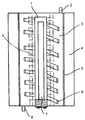
도 1은 본 발명에 따른 장치의 제1 실시 예의 단면도이다.
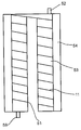
도 2는 광 촉매를 지지하고 있으며, 도 1에 도시된 장치의 일부를 형성하는 랙(rack)의 등각도이다.
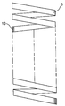
도 3은 도 1에 도시된 장치의 일부를 또한 형성하는 나선형 부재의 측면도이다.
도 4는 본 발명에 따른 장치의 제2 실시 예의 단면도이다.
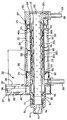
도 5는 본 발명에 따른 장치의 제3 실시 예의 단면도이다.
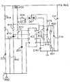
도 6은 제3 실시 예의 동작을 제어하며 제3 실시 예를 통해 전자기 코일들에 에너지 공급 전류를 공급하는 회로를 보여주는 회로도이다.
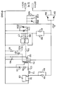
도 7은 장치의 제3 실시 예의 전기 모터 및 램프에 전력을 공급하는 회로를 보여주는 회로도이다.1 is a sectional view of a first embodiment of a device according to the invention;
Fig. 2 is an isometric view of a rack supporting a photocatalyst and forming part of the apparatus shown in Fig. 1; Fig.
3 is a side view of a helical member which also forms part of the apparatus shown in Fig.
4 is a sectional view of a second embodiment of the device according to the invention.
5 is a cross-sectional view of a third embodiment of the device according to the invention.
6 is a circuit diagram showing a circuit for controlling the operation of the third embodiment and supplying the energy supply current to the electromagnetic coils through the third embodiment.
7 is a circuit diagram showing a circuit for supplying electric power to the electric motor and the lamp of the third embodiment of the device.
장치의 각각의 실시 예는 자기력, 광 촉매 및 광-분해를 통해 ICE(Internal Combination Engine; 내부 결합 기관) 연료 연소 효율을 향상시키도록 의도되어 있는 기기를 포함한다. 이는 연료가 완전 연소를 위해 기관 실린더 내로 공급되기 전에 연료들이 자기력, 광 소스 및 광 촉매들을 통해 동시에 처리되는 것을 허용한다. 이는 탄소 배출량을 낮추고, 환경 오염을 완화하며 그리고 기관 효율을 향상시키는 이점들을 지니는 것으로 여겨진다.Each embodiment of the apparatus includes a device that is intended to improve internal combustion engine (ICE) fuel combustion efficiency through magnetic force, photocatalysis, and photo-decomposition. This allows the fuels to be processed simultaneously through magnetic forces, light sources and photocatalysts before the fuel is fed into the engine cylinders for complete combustion. This is believed to have the benefits of lowering carbon emissions, alleviating environmental pollution and improving engine efficiency.
상기 기기는 주로 광 촉매 채널로 이루어진다. 상기 채널은 자기장에 위치해 있으며 연료 파이프라인 상에 장착되어 있고, 상기 연료 파이프라인은 상기 연료 파이프라인의 일 단으로부터 상기 연료 파이프라인의 타 단으로 연료들을 이송한다. 이는 또한 175-400 ㎚ 파장의 전자기 방사선을 방출하는 광 소스를 포함하는 전자기 방사선 소스 수단을 에워싸고 있다. 상기 채널 내에는 광 촉매들이 배치되어 있다. 상기 자기장에 상기 채널을 노출하도록 상기 채널의 외부 상에 자기장 생성기가 존재한다. 상기 채널의 입구 및 출구 양자 모두는 상기 연료 파이프라인에 접속되어 시일링(sealing)된다. 자기 분포를 고르게 하는데 사용되는 나선들은 위에 기재한 광 촉매 채널 내에 배치되어 있다. 위에 기재한 광 촉매 채널은 원형, 나선형, 또는 구형이다. 나노 광 또는 흑색 광은 175-400 ㎚ 광 소스로부터의 광 방출들을 기술(記述)하는데 사용된 용어들이다. 상기 광 촉매들은 상기 채널의 내벽 상에 위치해 있으며 상기 채널의 내벽을 향해 상기 광 소스가 광을 방출한다. 상기 광 촉매들은 또한 상기 광 촉매 채널의 내부에나 또는 상기 광 소스가 광을 방출하는 상기 채널의 내벽 상에 위치해 있을 수 있다. 상기 광 촉매들은 상기 광 촉매 채널의 내벽 상에 위치해 있을 때 이산화 티타늄을 함유하는 피막들이다. 상기 광 촉매들은 또한 상기 채널 내부에 위치해 있을 때 이산화 티타늄을 함유하는 원통형 랙들 상에 존재한다. 상기 자기장은 영구 자석에 의해 생성되거나 전자기장이다. 자기 분포를 고르게 하는데 사용되는 나선들은 1-2개의 나란한 철판으로 이루어져 있다. 그러한 쌍의 철판들은 나선형 부재를 이루도록 얇은 알루미늄 시트로 덮이고 나선 형상으로 몰딩(molding)된다.The device is mainly composed of a photocatalytic channel. The channel is located in a magnetic field and mounted on a fuel pipeline, which transports the fuel from one end of the fuel pipeline to the other end of the fuel pipeline. It also encompasses electromagnetic radiation source means comprising a light source emitting electromagnetic radiation with a wavelength of 175-400 nm. Photocatalysts are disposed in the channel. A magnetic field generator is present on the exterior of the channel to expose the channel to the magnetic field. Both the inlet and the outlet of the channel are connected to the fuel pipeline and sealed. Spirals used to level the magnetic distribution are located within the photocatalytic channels described above. The photocatalytic channel described above is circular, spiral, or spherical. Nano or black light is a term used to describe the light emissions from a 175-400 nm light source. The photocatalysts are located on the inner wall of the channel and the light source emits light toward the inner wall of the channel. The photocatalysts may also be located within the photocatalytic channel or on the inner wall of the channel from which the light source emits light. The photocatalysts are films containing titanium dioxide when located on the inner wall of the photocatalytic channel. The photocatalysts are also present on cylindrical ladders containing titanium dioxide when located within the channel. The magnetic field is generated by a permanent magnet or is an electromagnetic field. The spirals used to level the magnetic distribution are made up of one or two parallel steel plates. Such pairs of steel plates are covered with a thin aluminum sheet to form a helical member and are molded into a helical shape.
상기 실시 예들은 연료들이 완전 연소를 위해 기관 실린더 내에 공급되기 전에 연료들이 자기장, 광 소스 및 광 촉매들을 통해 동시에 처리되는 것을 허용한다. 상기 실시 예들에 의해 탄소 배출량이 감소하게 될 수 있고, 환경 오염이 완화하게 될 수 있으며 그리고 기관 효율이 향상하게 될 수 있다.These embodiments allow the fuels to be processed simultaneously through magnetic fields, light sources and photocatalysts before they are fed into the engine cylinders for complete combustion. The above-described embodiments can reduce carbon emission, mitigate environmental pollution, and improve engine efficiency.
상기 연료들은 폭연(deflagration)을 위해 기관에 공급되기 전에 자기장, 175-400 ㎚의 광 소스, 및 광 촉매들에 동시에 노출될 수 있다. 상기 자기장, 상기 175-400 ㎚의 광 소스, 및 상기 광 촉매들은 동시에 상기 연료들 상에 작용한다.The fuels may be simultaneously exposed to a magnetic field, a light source of 175-400 nm, and photocatalysts before being fed to the engine for deflagration. The magnetic field, the 175-400 nm light source, and the photocatalysts simultaneously act on the fuels.
ICE 연료들은 일반적으로 휘발유, 경유, 등유, 에탄올, 가솔린 및 메탄올과 같은 유기 액체들, 및 액화 가스, 천연 가스 및 알코올 등과 같은 유기 가스들을 언급한다. 상기 ICE 연료들은 주로 유기 화합물들, 예를 들어 알칸들, 방향족 탄화수소들, 벤젠 및 수산기의 혼합이다. 상기 연료들 모두는 긴 탄소 사슬들 및 무거운 분자들을 지니는 유기 혼합물들이다. 분자들이 무거울수록 분자들이 더 들러붙고 분자들이 가벼울수록 분자들의 발열량이 크고 분자들의 분무 연소가 양호해진다. 수산 유리기들은 고 에너지 연료들이다. 최근의 연소 이론들에서는 유기 화합물들의 산화가 사실상 유리기들에 의한 일련의 사슬 반응들이라고 제시되어 있다. 부정적인 연소 생성물들의 생성 및 연소 속도는 유리기들이 중합하게 되는 분자 사슬들의 상태에 의해 영향을 받는다. 유기 화합물들의 분자 사슬들의 길이는 연소 반응들에서의 에너지 레벨을 지시한다. 페놀 및 알콜과 같은 화합물들은 연소를 추진하는 수소 및 수산기 이온으로 분해될 수 있다. 금속 이온들이 없는 유기 연료들은 더 신속하고 더 완전하게 연소한다. 무기 염들은 환경을 오염시키는 산화물들을 생성하기 어렵다. 자기장을 통과하는 연료들은 촉매 및 산화된다. 연료 가스 분자 사슬들이 끊겨 수산 유리기들이 방출하게 된다. 상기 유리기들에서의 티올 및 티오펜은 수소로 분해되어 대량의 유리기들 및 수소가 생성하게 된다. 유리기들이 중합하게 되면, 중합체 분자 운동들을 하게 하는 브라운 운동(Brownian motion)은 연소 속도를 가속화하는 중공 관형 운동(hollow tubular motion)이 전환된다. 그러는 동안에, 본원의 연료들의 광 촉매들이 175-400 ㎚의 광파들에 노출된다. 상기 광 촉매들은 상기 광으로부터 에너지를 흡수하여 전자-정공(electron-hole) 쌍들을 형성한다. 그러한 쌍들(광 캐리어들)은 신속하게 표면으로 이동하여 상기 표면에 부착되는 H20 및 O2를 활성화한다. 그리고나서, 수산기(-OH) 및 활성 산소(-O)는 연소 속도를 높이도록 생성된다. 휘발유는 10,500 kcal/리터의 연소 값을 지니고 수소는 20,000 kcal/리터의 연소 값을 지닌다. 수소는 단지 휘발유가 필요한 것의 1/6 정도인 소량의 점화 에너지를 필요로 한다. 수소 연소 화염의 이동 속도는 휘발유 연소 화염의 이동 속도보다 9배 빠르다. 연료들에 수소를 첨가하는 것은 화염의 이동 속도를 가속화하여 발열량들의 에너지 방출 베이스를 강화한다. 그리고나서, 하이브리드 가스(hybrid gas)는 좀더 신속하게 점화하고 좀더 빠르게 연소하여 화재 사고들로부터 생성되는 부정적인 반응 물질들 및 에너지 낭비를 회피한다. 생성되는 무기 염들은 산화물들의 생성을 줄일 수 있고 오염을 줄이면서 에너지를 절약할 수 있다.ICE fuels generally refer to organic liquids such as gasoline, diesel, kerosene, ethanol, gasoline and methanol, and organic gases such as liquefied gases, natural gas, and alcohols. The ICE fuels are primarily mixtures of organic compounds, such as alkanes, aromatic hydrocarbons, benzene, and hydroxyl groups. All of the fuels are organic compounds having long carbon chains and heavy molecules. The heavier the molecules, the more molecules attach and the lighter the molecules, the higher the calorific value of the molecules and the better the atomization of the molecules. Free acids are high-energy fuels. Recent combustion theories suggest that the oxidation of organic compounds is in effect a series of chain reactions by free radicals. The production and combustion rates of negative combustion products are influenced by the state of the molecular chains in which the free radicals polymerize. The length of the molecular chains of organic compounds indicates the energy level in the combustion reactions. Compounds such as phenols and alcohols can be decomposed into hydrogen and hydroxyl ions to propel combustion. Organic fuels without metal ions burn faster and more completely. Inorganic salts are difficult to generate oxides that pollute the environment. Fuel passing through the magnetic field is catalyzed and oxidized. Fuel gas molecules chains are broken and free radicals release. The thiols and thiophenes in these free radicals are broken down into hydrogen to produce large amounts of free radicals and hydrogen. When free radicals polymerize, Brownian motion, which causes polymer molecular motions, is converted to hollow tubular motion, which accelerates the rate of combustion. In the meantime, the photocatalysts of the fuels of the present invention are exposed to light waves of 175-400 nm. The photocatalysts absorb energy from the light to form electron-hole pairs. Such pairs (optical carriers) rapidly move to the surface and activate H 2 O and O 2 attached to the surface. Then, the hydroxyl group (-OH) and the active oxygen (-O) are generated so as to increase the burning rate. Gasoline has a combustion value of 10,500 kcal / liter and hydrogen has a combustion value of 20,000 kcal / liter. Hydrogen requires a small amount of ignition energy, which is about one sixth of what gasoline requires. The movement speed of hydrogen combustion flame is 9 times faster than that of gasoline combustion flame. The addition of hydrogen to the fuels accelerates the rate of flame movement and enhances the energy release base of the calorific values. Then, the hybrid gas ignites more quickly and burns faster, avoiding negative reactants and energy wastes generated from fire accidents. The resulting inorganic salts can reduce the production of oxides and save energy while reducing contamination.
ICE 구조 설계들을 변경하지 않으면서, 각각의 실시 예는, 에너지 방출 베이스를 강화하고, 연료 연소 속도를 높이며, 초기의 증강된 방식으로 에너지 방출 과정을 완료하도록 연소 곡선을 굴절시키고 그러는 동안에 황화물과 같은 무기 화합물들은 상기 에너지 방출 과정에서 염들로 전환됨으로써 환경 오염이 완화된다. 실험들에서는 이러한 해결수단의 적용이 연소 곡선들을 굴절시켜 초기의 증강된 방식으로 상기 에너지 방출 과정을 완료한다고 제시되어 있다. 기관 소음은 상당히 감쇠하게 되고 토크는 대단히 강화하게 된다. 기관 효율은 상당히 증가하게 되고 부정적인 연소 생성물들은 효율적으로 줄어들게 된다.Without altering the ICE structure designs, each embodiment can be used to refine the combustion curve to enhance the energy release base, increase the fuel burn rate, complete the energy release process in an initial enhanced fashion, The inorganic compounds are converted into salts in the energy release process, thereby alleviating environmental pollution. In experiments it has been suggested that the application of this solution would refract the combustion curves to complete the energy release process in an initially enhanced manner. Engine noise is considerably damped and torque is greatly enhanced. Engine efficiency increases significantly and negative combustion products are effectively reduced.
도 1 - 도 4에는 자력, 광 촉매들 및 광-분해를 통해 ICE 연료 연소 효율을 향상시키도록 설계된 기기가 예시되어 있다. 상기 기기는 주로 광 촉매 채널(3)로 이루어져 있고, 상기 광 촉매 채널(3)에서는 사용시 연료가 폭연을 위해 기관 내로 공급되기 전에 자기장, 175-400 ㎚의 광 소스, 및 광 촉매들에 동시에 노출된다.Figures 1 - 4 illustrate a device designed to improve ICE fuel combustion efficiency through magnetic force, photo catalysts and photo-decomposition. The device is mainly composed of a
상기 광 촉매 채널은 자기장 내에 위치해 있으며 연료 파이프라인 상에 장착되어 있고, 상기 연료 파이프라인은 상기 연료 파이프라인의 일 단부로부터 상기 연료 파이프라인의 타 단부로 연료들을 이송한다. 이는 또한 175-400 ㎚에서 광을 방출하는 광 소스를 에워싸고 있다. 광 촉매들은 상기 채널(3) 내에 배치되어 있다. 상기 자기장에 상기 채널(3)을 노출하도록 상기 채널(3)의 외부 상에 자기장 생성기(4)가 존재한다. 상기 채널(3)의 입구(8) 및 출구(2) 양자 모두는 상기 연료 파이프라인에 접속되어 시일링(sealing)된다.The photocatalytic channel is located in a magnetic field and is mounted on a fuel pipeline, which transports the fuel from one end of the fuel pipeline to the other end of the fuel pipeline. It also encompasses a light source emitting light at 175-400 nm. Photocatalysts are arranged in the channel (3). A magnetic field generator (4) is present on the exterior of said channel (3) to expose said channel (3) in said magnetic field. Both the
도 3을 참조하면, 나선형 부재(6)를 형성하는 나선들은 자기 분포를 고르게하는데 사용되며 상기 광 촉매 채널(3) 내에 배치된다. 그러한 나선들은 2개의 나란한 철판(10)으로부터 형성된다. 그러한 쌍의 철판들(10)은 얇은 알루미늄 시트로 덮이고 나선 형상으로 몰딩(molding)된다. 상기 철판들(10)은 상기 촉매 채널 내에 자기장을 균일하게 분포하는 역할을 하며, 자기력을 받은 상기 채널(30) 내에서의 연료의 촉매 및 산화를 촉진한다.Referring to Fig. 3, the spirals forming the
위에 설명한 촉매 채널은 원통형이지만 다른 실시 예들에서는 원형, 나선형, 또는 구형일 수 있다. 나노 광 또는 흑색 광은 175-400 ㎚의 광 소스(7)에 의해 방출되는 전자기 방사선이다. 위에 설명한 광 촉매들은 상기 채널(3)의 내벽 상에 위치해 있으며 상기 채널(3)의 내벽을 향해 상기 광 소스(7)가 광을 방출하고, 위에 설명한 광 촉매들은 또한 상기 광 촉매 채널(3) 내부에 제공되어 있다. 좀더 구체적으로 기술하면, 상기 광 촉매들은 상기 광 촉매 채널(3)의 내벽 상에 이산화 티타늄을 함유하는 피막(5) 내에 포함되어 있다. 상기 광 촉매들은 또한 상기 채널 내부에 위치해 있을 때 이산화 티타늄을 함유하는 원통형 랙(9)에 도포되어 있다.The catalyst channels described above are cylindrical, but in other embodiments they may be circular, spiral, or spherical. Nano or black light is electromagnetic radiation emitted by a
도 1에 도시된 바와 같이, 상기 광 촉매 채널(3)은 상기 광 소스(7)를 에워싸고 있으며 연료들이 상기 광 촉매 채널(3)을 통과하는 것을 허용한다. 투명한 원형 실드(transparent circular shield)는 상기 채널(3) 중앙에 하우징되어 있으며 상기 광 소스의 형상에 상응한다. 상기 실드는 챔버(1)를 한정하며 상기 챔버(1)는 상기 투명한 원형 실드의 중심에 상기 광 소스를 수용한다. 상기 채널(3)의 내벽은 이산화 티타늄(5)을 함유하는 피막들을 지닌다. 상기 채널(3) 내부에는, 이산화 티타늄을 구비하는 원통형 랙(9)이 설치되어 있다. 도 2를 참조하면, 상기 이산화 티타늄은 상기 원통형 랙(9)의 외부 표면에 피막으로서 도포된다. 이는 연료들이 사전협의(conversation)를 위해 광 촉매들과 만나게 되는 경계면(interface)를 연장하기 위한 것이다. 반사 피막들은 직접광 및 반사광이 상기 채널을 통과하는 연료들에 작용하는 것을 허용하도록 (상기 채널(3)을 에워싸고 있는) 자기장 생성기(4)에 대한 상기 투명 채널(3)의 외부 표면에 도포될 수 있다. 그리고나서, 광-분해 결과들은 강화하게 된다. 상기 투명한 실드는 투명한 내열 재료, 예를 들면 내열 유리로 만들어진다.As shown in FIG. 1, the
도 2를 참조하면, 상기 랙(9)은 대체로 원통형이며, 6개의 동축 링(12-17)으로부터 형성되고 상기 6개의 동축 링(12-17)은 나란하며 상기 랙(9)에 의해 한정된 원통의 축 방향으로 일정한 간격을 두고 떨어져 있다. 상기 링들은 상기 랙(9)에 의해 한정된 원통의 축과 나란하게 연장되어 있는 일직선으로 나란한 타이 바(tie bar)들(18-27)에 의해 결합되어 있다. 상기 타이 바들(18-27) 및 링들은 적합한 금속의 와이어로 형성될 수 있으며 상기 타이 바들 및 링들은 적합한 수단에 의해, 예를 들면 함께 용접됨으로써 결합하게 될 수 있다. 상기 랙(9) 전체는 티타늄의 어두운 측면을 갖는 광 촉매로 피복된다. 상기 타이 바들(18-27)은 임의의 인접 쌍의 타이 바들 간의 각도 간격이 일정하도록 상기 링들 주변에 규칙적으로 배치되어 있다.2, the
도 4에 도시된 실시 예에서는, 여러 구성요소들이 상기 제1 실시 예의 구성요소들에 상응하며, 이들은 50만큼 높여진 도 1 - 도 3의 참조번호들로 나타나 있다. 도 4에서는, 상기 광 소스 및 랙이 명확성을 위해 생략되었다. 상기 제2 실시 예는 상기 나선형 부재(6)에 상응하는 구성요소를 지니지 않지만, 그 대신에 입구(52) 및 출구(58) 사이의 나선형 경로를 한정하는 베인(vane)들(11)의 나선형 배치를 포함한다.In the embodiment shown in Fig. 4, the various components correspond to the components of the first embodiment, which are indicated by the reference numerals of Figs. 1 - 3 raised by 50. In Fig. 4, the light source and the rack have been omitted for the sake of clarity. The second embodiment does not have a component corresponding to the
따라서, 상기 광 소스를 에워싸고 있으며 연료들이 통과하는 것을 허용하는 상기 채널은 상기 광 소스를 포위하는 나선 채널이다. 나선 베인들 또는 세퍼레이터(separator)들(11)은 연료들이 마지막으로 하부에 있는 출구로 향하기 전에 단지 상부에 있는 입구로부터 진입한 다음에 상기 나선 채널의 형상으로 흐르도록 상기 투명한 원형 실드 내에 위치해 있다. 이러한 타입의 채널은 자기장, 광, 광 촉매 재료들과 연료들 간의 접촉을 연장시켜 사전협의 시간을 연장하는데 도움을 준다. 이산화 티타늄을 지니는 피막들은 상기 나선 채널의 내벽에 도포된다. 원통형 랙들은 상기 채널 내에(상기 실드(1) 및 베인들(11)의 반경 방향의 내부 에지들 간에) 설치된다.Thus, the channel surrounding the light source and allowing fuels to pass is a spiral channel surrounding the light source. Spiral vanes or
어느 한 실시 예에서는, 상기 자기장이 자기장 생성기(4, 54)에 의해 생성된다. 상기 생성기는 영구 자석 또는 전자기 생성기 중 어느 하나일 수 있는데, 그 이유는 후자, 즉 전자기 생성기가 또한 자기장을 생성하기 때문이다. 이러한 예들에서는, 상기 자기장이 포지티브(positive) 및 네거티브(negative) 방형파(square wave) 생성기들, 전력 증폭기들 및 전압 안정기들을 특징으로 하는 전력 제어기들에 의해 구동되는 자기장 생성 코일들에 의해 제공된다. 자동차용 배터리들은 상기 제어기들을 충전하며, 상기 포지티브 방형파 생성기들을 통해 전기가 흐르게 되면, 100-500 ㎐의 포지티브 및 네거티브 방형파들이 생성된다. 상기 전력 증폭기들에 의해 증폭된 후에, 상기 파들은 상기 자기장 생성 코일들 내로 공급되고 자기장은 상기 코일들 내에 생긴다. 전압 안정기들을 통해 상기 투명한 실드 내의 광 소스로 전원이 전기를 제공한다. 포지티브 방형파 생성기들, 전력 증폭기들 및 전압 안정기들은 모두 시장에서 입수가능하다. 상기 포지티브 방형파 생성기들, 상기 전력 증폭기들 및 상기 전압 안정기들은 전통적인 회로들로 대체될 수 있지만, 사용되는 회로들이 100-500 ㎐의 포지티브 및 네거티브 방형파들을 생성하는 포지티브 방형파 생성기들을 지니는 것이 바람직하다. 전력 증폭기들에 의해 증폭되어 상기 자기장 생성 코일들 내로 공급된 후에, 상기 파들은 100-500 Gs의 자속 밀도와 동등한 자기력을 생성할 수 있다. 상기 자기장 생성기는 상기 광 촉매 채널의 외부 상에 있으며, 상기 촉매 채널은 상기 생성기에 의해 생성된 자기장 내에 있다.In one embodiment, the magnetic field is generated by a magnetic field generator (4, 54). The generator may be either a permanent magnet or an electromagnetic generator, because the latter, i.e., the electromagnetic generator also generates a magnetic field. In these examples, the magnetic field is provided by magnetic field generating coils driven by power controllers characterized by positive and negative square wave generators, power amplifiers and voltage stabilizers . Automotive batteries charge the controllers, and when electricity is passed through the positive square wave generators, positive and negative square waves of 100-500 Hz are generated. After being amplified by the power amplifiers, the waves are fed into the magnetic field generating coils and a magnetic field is generated in the coils. Voltage stabilizers provide power to the light source in the transparent shield. Positive square wave generators, power amplifiers and voltage stabilizers are all available on the market. The positive square wave generators, the power amplifiers and the voltage stabilizers can be replaced by conventional circuits, but it is preferred that the circuits used have positive square wave generators producing positive and negative square waves of 100-500 Hz Do. After being amplified by the power amplifiers and fed into the magnetic field generating coils, the waves can produce a magnetic force equivalent to a magnetic flux density of 100-500 Gs. The magnetic field generator is on the outside of the photocatalytic channel and the catalytic channel is in a magnetic field generated by the generator.
프로그램된 유닛은 또한 마치 축전 배터리들과 같은 변환 지원 전력 회로들을 지니는 본원의 자기장 생성기 및 광 소스를 제공할 수 있다. 상기 유닛은 상기 광 소스를 제어하고 변조된 자기장을 생성한다. 전자기 생성기는 또한 변조된 자기장을 생성할 수 있다. 그러한 자기장은 자기장 생성 코일들로 형성된다. 자동차용 축전 배터리들은 상기 프로그램된 유닛을 통해 100-500 ㎐의 포지티브 및 네거티브 방형파들을 생성하고, 상기 방형파들을 자기장 생성 코일들 내로 공급한다. 그리고나서, 변조된 자기장은 상기 코일들 내에 유도된다. 상기 프로그램된 유닛을 통해 상기 투명한 실드 내의 광 소스로 전원이 전기를 제공한다. 상기 프로그램된 유닛의 프로그램 제어형 IC 회로 구성요소들 모두는 시장으로부터 입수가능하므로 그 세부사항들이 반복되지 않을 것이다. 상기 자기장 생성기는 상기 광 촉매 채널의 외부 상에 있으며 상기 촉매 채널은 상기 생성기에 의해 생성되는 변조된 자기장 내에 있다. The programmed unit may also provide the magnetic field generator and the light source of the present invention having conversion-assisted power circuits such as battery cells. The unit controls the light source and generates a modulated magnetic field. The electromagnetic generator may also generate a modulated magnetic field. Such a magnetic field is formed by the magnetic field generating coils. Automotive battery batteries generate positive and negative square waves of 100-500 Hz through the programmed unit and supply the square waves into the magnetic field generating coils. The modulated magnetic field is then induced in the coils. The power is supplied to the light source in the transparent shield through the programmed unit. All of the programmed IC circuit components of the programmed unit are available from the market, so the details will not be repeated. The magnetic field generator is on the outside of the photocatalytic channel and the catalytic channel is in a modulated magnetic field generated by the generator.
각각의 실시 예는 기관 부근에의 연료 입구의 설치를 위한 것이며 자기장 생성 코일들이 자기장을 생성하는 것을 돕도록 상응하는 기관 또는 차량 상에 장착되어 상기 자동차용 축전 배터리들에 접속되게 된다. 상기 입구를 통해, 연료들이 먼저 상기 광 소스를 에워싸고 있으며 연료들을 전달하는 광 촉매 채널에 진입한다. 상기 연료들은 더 나은 기관 효율 및 연료 절약을 이루도록 폭연을 위해 기관 내로 공급하기 전에 상기 자기장, 상기 175-400 ㎚의 광 소스 및 상기 광 촉매들에 동시에 노출된다.Each embodiment is for the installation of a fuel inlet in the vicinity of the engine and is mounted on a corresponding engine or vehicle to assist the magnetic field generating coils to generate a magnetic field and to be connected to the vehicle battery batteries. Through the inlet, the fuels first enter the photocatalytic channel surrounding the light source and delivering the fuels. The fuels are simultaneously exposed to the magnetic field, the 175-400 nm light source, and the photocatalysts before feeding into the engine for detonation to achieve better engine efficiency and fuel economy.
본 발명에 따른 기기는 연료들이 완전한 연소를 위해 기관 실린더 내로 공급되기 전에 자기장, 광 소스 및 광 촉매들을 통해 동시에 처리되는 것을 허용한다. 이는 탄소 배출량을 줄이고, 환경 오염을 완화하며 기관 효율을 향상시키는 이점들을 지닌다.The device according to the invention allows the fuels to be processed simultaneously via magnetic fields, light sources and photocatalysts before being fed into the engine cylinders for complete combustion. This has the advantages of reducing carbon emissions, mitigating environmental pollution and improving engine efficiency.
본 발명에 따른 장치의 제3 실시 예가 도 5 - 도 7을 참조하여 지금부터 설명될 것이다.A third embodiment of the device according to the invention will now be described with reference to Figures 5-7.
이러한 경우에, 가늘고 긴, 저압 수은 방전 램프(30)는 중공 원통형 하우징(32) 내에 포함되어 있으며, 상기 중공 원통형 하우징(32)은 금속 또는 다른 어떤 적합한 재료로부터 형성되고 3 부분 구성으로 이루어져 있으며 양단부에서 2개의 단부 캡(36, 38)에 부착된 원통형 몸체부(34)를 지니고, 상기 2개의 단부 캡(36, 38)은 상기 몸체부 및 각각의 단부 캡 사이에 제공된 나사의 나사산이 있는 커넥터(connector)들(40, 42)에서 상기 몸체부에 부착되어 있다.In this case, the elongated, low-pressure
상기 캡(36)은 상기 장치용 입구로서의 역할을 하는 호스 커넥터(hose connector)(44)를 구비하고 있다. 상기 커넥터(44)는 어느 적합한 수단에 의해 상기 캡에 부착되어 있고, 다시 어느 적합한 수단에 의해 상기 캡에 시일링된다. 상기 커넥터(44)는 통로(46)의 한 단부를 한정하며, 상기 통로(46)는 상기 캡(36)을 통해 그리고 상기 하우징(32)의 내부로 연장되어 있다.The
상기 하우징(32)은 중공 원통형 코어 피스(hollow cylindrical core piece)를 수용하며 상기 중공 원통형 코어 피스는 상기 하우징(32) 및 광 소스(30)와 동축이며 상기 단부 캡(36)으로부터 상기 하우징을 따라 상기 단부 캡(38)으로 연장되어 있다. 상기 코어 피스(48)는 비-강자성 재료로부터 형성되며 상기 캡들(36, 38)에서 어느 적합한 수단, 예를 들면 나사의 나사산이 있는 커넥터에 의해서나 용접됨으로써 상기 하우징(32)에 부착된다.The
상기 코어 피스(48) 및 상기 단부 캡들(36, 38) 간의 액밀(液密) 시일(liquid tight seal)이 O 링 시일들(50, 52)에 의해 제공된다.A liquid tight seal between the
상기 캡(36)은 원통형 단부 벽(37)을 포함하며, 상기 원통형 단부 벽(37)은 상기 램프(30)의 인접 단부의 위치를 지정하기 위한 블라인드 소켓(blind socket)을 한정한다.The
상기 코어 피스(48)는 3개의 외향 환형 플랜지(54, 56, 58)를 포함하며, 상기 3개의 외향 환형 플랜지(54, 56, 58)는 상기 하우징(32)의 부분(34)과 함께 한 쌍의 축 방향으로 이격된 원통형 랙들(60, 62)을 한정하고, 상기 한 쌍의 축 방향으로 이격된 원통형 랙들(60, 62)은 상기 코어 피스(48) 및 상기 램프(30)와 동축이며 상응하는 동축 코일들(64, 66)을 수용하며, 상기 동축 코일들(64, 66) 각각은 상기 랙들(60, 62) 중 대응하는 랙 상에 감겨 있다.The
상기 코일들(64, 66)은 적합한 도체로 이루어져 있으며 전자기 코일들로서의 역할을 한다. 상기 코일들은 서로 동일한 권선수를 지니지만, 상기 랙(60) 및 랙(62) 상에 반대 방향으로 감겨 있으며 서로 직렬로 구동 회로에 접속되어 있고 그럼으로써 상기 구동 회로로부터의 전류가 상기 코일들을 통해 반대 방향으로 흐르게 된다. 따라서, 상기 코어(54)는 상기 코일들(64, 66)을 지지하기 위한 랙으로서의 역할을 한다.The
상기 단부 캡(38)은 출구 호스 커넥터(68)를 포함하며, 상기 출구 호스 커넥터(68)를 통해 연료가 처리된 후에 상기 장치를 나간다.The
상기 캡(38)의 외측 단부는 나사의 나사산이 있는 커넥터(70)를 포함하며, 상기 나사의 나사산이 있는 커넥터(70) 상에는 부가적인 단부 캡(72)이 장착되어 있다. 도 5로부터 볼 수 있는 바와 같이, 상기 캡(72)은 상기 램프(30)의 단자들(74)에 대한 접근을 허용하도록 개방형으로 이루어져 있다. 상기 램프(30) 및 상기 캡(72) 간의 연료 누설은 환형 O 링 시일(76)에 의해 방지된다. 부가적인 업스트림 환형 O 링 시일(78)은 또한 상기 램프(30)의 본체 및 상기 캡(38) 사이에 제공되어 있으며, 또한 상기 캡(38)으로부터의 오일 누설을 방지하는데 도움을 준다.The outer end of the
상기 캡(38)에는 또한 장착용 러그(80)가 제공되어 있으며 상기 장착용 러그는 (맞은 편에서 볼 때) 대체로 원형이며 상기 장착용 러그를 통해 DC 전기 모터(82)가 상기 장치에 부착된다. 상기 러그(80)는 애퍼처(aperture)(84)를 지니며 상기 애퍼처(84)를 통해 상기 모터가 연장되어 있고, 상기 모터는 출력 샤프트(86)를 지니며 상기 출력 샤프트(86)는 상기 모터의 나머지 부분으로부터 상기 러그(80)의 반대편으로 연장되어 있고 체결용 너트(90)에 의해 상기 샤프트(86) 상에 유지된 외부에 나사산이 있는 기어 휠(88)에 부착되어 있다. 부품 원통형 코웰(part cylindrical cowell)(92)은 상기 러그(80)와 함께 상기 기어 휠(88)을 수용하기 위한 원통형 챔버(94)를 한정한다.The
상기 챔버(94)는, 도 5에 도시된 바와 같이 보인 장치에 의하면, 상기 챔버(94)의 상부 영역이 개방되어 있고, 그럼으로써 상기 기어 휠(88)은 외부에 나사산이 있는 환형 링(annular ring)(94)과 맞물리게 되고, 상기 환형 링(94)은 상기 캡(38) 상에 회전가능하게 장착되어 있으며, 상기 램프(30) 및 코어 피스(48)와 동축으로 배치되어 있고 그리고 자기 결합(magnetic linkage)의 제1 자기 커플링 부재를 제공하며 상기 자기 결합의 제1 자기 커플링 부재를 통해 상기 모터(82)가 상기 램프(30) 주위로 랙 및 나선형 부재 어셈블리(96)를 회전시킬 수 있게 한다.5, the
이를 위해, 상기 환형 링(94)은 다수의 반경 방향으로 위치해 있는 영구 자석(도시되지 않음)을 포함하며, 상기 영구 자석들은 번갈아 바뀌는 극성들 때문에 상기 링 내에서 등각도(等角度)로 배치된다. 따라서, 예를 들면, 자신의 반경 방향의 내부 극으로서 북극으로 배치되는 그러한 자석들 중 하나는 2개의 다른 자석에 의해 측면에 배치되며 상기 2개의 다른 자석 각각에서는 남극이 반경 방향으로 가장 안쪽에 있게 된다. 상기 자기 결합의 제2 커플링 부재는 내부 환형 링(98)을 포함하며, 상기 내부 환형 링(98)은 유사한 자석들의 배치(도시되지 않음)를 포함하고 상기 하우징(32) 내에 장착되어 있다. 사용시, 상기 모터(82)의 동작은 상기 기어 휠(88)을 회전시키고 상기 기어 휠(88)은 다시금 상기 링(94)을 회전시킨다. 이는 다시금 상기 링들 간의 자기 커플링 때문에 상응하는 상기 링(98)의 회전을 일으키고, 그럼으로써 상기 링(98)에 직접 접촉하는 트랜스미션(transmission) 없이도 상기 링(98)에 구동이 전달될 수 있게 한다.To this end, the
상기 랙 및 나선형 부재 어셈블리는 상기 하우징(32)의 내부 길이의 상당 부분을 따라 연장되어 있고, 랙(100)을 포함하며 상기 랙(100)은 일단이 상기 링(98)에 부착되어 있으며 상기 램프(30)를 지탱하고 또한 상기 램프(30)를 중심으로 회전가능하다. 상기 랙의 일반적인 구조는 여러 면에서 도 2에 도시된 랙과 유사하다. 따라서, 상기 랙(100)은 8개의 동축 링(예를 들면 링(102))을 지닌다. 그러나, 이러한 경우에, 이러한 링들 각각은 대체로 원통형이다. 도 2 랙의 타이 바들 대신에, 상기 링들 각각이 또한 상기 램프(30)를 지탱하는 상기 커넥터(104)와 같은 다수의 등각도로 이격된 블레이드(blade) 같은 커넥터들을 통해 자신의 이웃하는 링들에 부착된다. 이러한 커넥터들 각각은 상기 램프(30)를 지탱하고 그럼으로써 상기 랙(100)이 상기 램프(30)를 중심으로 회전함에 따라, 상기 랙(100)이 상기 램프(30)의 표면을 깨끗하게 한다. 상기 랙(100)의 링(102)과 같은 링들은 또한 이러한 회전 동안 클리닝 효과를 지닐 수 있다. 나선형 형태로 절단 및 형상화된 실리콘 강판으로부터 형성된 나선형 부재(106)는 다수의 상기 랙(100)의 링들의 외부 표면들에 부착되고, 그럼으로써 또한 상기 링들과 동축으로, 결과적으로는 상기 램프(30) 및 하우징(32)와 동축으로 배치된다.The rack and spiral member assembly extends along a substantial portion of an interior length of the
이산화 티타늄 촉매는 또한 상기 랙(100)의 링들의 노출된 외부 표면들 상에 피복될 수 있지만, 이 같은 특정한 경우에, 이산화 티타늄 광 촉매는 마치 피막(108)과 같이 상기 코어 피스(48)의 내부 표면에 도포된다.Titanium dioxide photocatalyst may be coated on the exposed outer surfaces of the rings of the
도 5에서 볼 수 있는 바와 같이, 상기 피막(108) 및 상기 나선형 부재(106)의 반경 방향 외부면들 간의 공간, 상기 랙(100)의 노출된 부분들 및 상기 램프의 노출된 부분들(다시 말하면, 임의의 시간에 상기 랙에 의해 커버되지 않는 부분들) 은 채널을 제공하며 상기 채널을 통해, 상기 커넥터(44)를 통해 유입된 연료가 상기 장치를 통과하고 상기 커넥터(68)를 통해 유출된다.As can be seen in FIG. 5, the spacing between the radially outer surfaces of the
연료가 상기 장치를 통과하는 동안, 상기 연료는 상기 램프(30)로부터의 자외 방사선에 노출되고, 상기 코일들(64, 66)에 의해 생성된 자기장에 노출되며 그리고 상기 램프(30)로부터의 광에 의해 활성화된 광 촉매 피막(108)에 노출된다. 그 외에도, 상기 코일들(64, 66)에 의해 생성된 자기장은 상기 나선형 부재(106)에서 자체적으로 자기장을 생성하는 전류를 유도한다. 이는 연료가 받게 되는 자기장이 광물 성분들을 분리시키는데 도움을 주고 그럼으로써 상기 광물 성분들이 후속 연소 과정을 방해하지 않게 하는 것으로 여겨진다. 상기 기기의 동작 동안, 상기 모터(82)는 상기 랙(100) 및 나선형 부재(106)를 회전시킨다. 이러한 회전은 상기 연료의 처리에 도움을 주는 것으로 여겨지며 상기 회전으로 상기 랙(100)이 위에서 논의된 바와 같이 상기 램프(30)의 외부 표면을 깨끗하게 한다.The fuel is exposed to ultraviolet radiation from the
상기 램프(30)는 현재 모델들에서 8 와트 및 14 와트 간의 전력 출력을 지니고(좀더 높은 전력 출력의 램프가 또한 채택될 수 있음), 현재 모델에서 10 및 20 ㎝ 간의 길이를 지닌다. 상기 램프의 실제 전력 및 치수들(및 상기 장치의 나머지 부분의 관련 치수들)은 처리해야 할 연료의 특성, 및 처리된 연료가 공급되어야 할 기관의 크기에 의존하여, 실시 예들마다 다를 수 있다.The
사용시, 상기 코일들(64, 66)에는 (상기 제1 실시 예의 장치와 같이) 100-500 ㎐ 주파수의 교류 방형파 전류가 공급된다. 이러한 전류는 도 6에 도시된 회로에 의해 공급된다. 그 회로는 2개의 집적 회로(IC2, IC3)에 기반하여 이루어진다. 집적 회로(IC2)는 참조 MM358 8-DIP으로 지정된 타입일 수 있지만, 집적 회로(IC3)는 참조 LM2525A16-DIP으로 지정된 타입일 수 있다.In use, the
도 6에 도시된 회로는 기관의 활성화를 나타내는 신호를 수신하는 입력을 포함하고, 기관의 작동이 도 6의 회로를 자동으로 트리거하여 상기 램프(30) 및 상기 모터(82)를 활성화하게 함과 아울러, 상기 코일들(64, 66)에 에너지 공급 전류의 공급을 트리거하게 하도록 구성되어 있다.The circuit shown in Fig. 6 includes an input for receiving a signal indicative of the activation of the engine, and the operation of the engine automatically triggers the circuit of Fig. 6 to activate the
숙련된 자라면 입력이 이를 달성하기 위해 접속되어야 하는 시스템을 이해하겠지만, 일 예는 차량의 연료 펌프 제어 시스템일 것이다.One skilled in the art will understand the system in which the inputs must be connected in order to achieve this, but an example would be a fuel pump control system of the vehicle.
활성화 신호에 대한 도 6의 회로 상의 입력은 좌측 상단 모서리에 있는 입력 A이며, 이를 통해 도 6의 회로가 도 7의 회로의 입력 A에 접속된다. 도 7의 회로는 DC V+ 및 DC V- 단자들을 포함하며, 상기 단자들은 활성화를 나타내는 신호를 수신하고, 이로 인해 도 7의 회로가 도 6 회로의 입력 A에서 활성화 신호를 제공한다.The input on the circuit of Fig. 6 for the activation signal is input A at the top left corner, through which the circuit of Fig. 6 is connected to the input A of the circuit of Fig. The circuit of FIG. 7 includes DC V + and DC V- terminals, which receive signals indicative of activation, thereby causing the circuit of FIG. 7 to provide an activation signal at input A of FIG. 6.
상기 코일들(64, 66)에 에너지를 공급하기 위한 교류용 출력은 상기 회로의 우측에 단자들(B2-AC 25 ㎐, AC 25 ㎐)에 의해 제공된다.An AC output for supplying energy to the
도 6에 도시된 회로는 도 7의 회로의 단자 A에 접속되어 있는 단자 A를 포함한다. 도 7의 회로는 집적 회로(IC4)에 기반하여 이루어지며, 상기 집적 회로(IC4)는 참조 IR2520D 도 8 PIN으로 지정된 타입일 수 있다. 전력이 도 7의 회로의 단자 A로 수신되는 경우에, 도 7의 회로는 시동하여 위에서 설명한 바와 같이 상기 램프(30)가 자외 방사선을 방출하게 하도록 상기 램프(30)를 구동시킨다.The circuit shown in Fig. 6 includes a terminal A connected to terminal A of the circuit of Fig. The circuit of Fig. 7 is based on an integrated circuit IC4, and the integrated circuit IC4 may be of the type designated by
본 명세서에 첨부된 표들은 상기 회로들의 여러 구성요소의 세부들을 보여준다.The tables attached herewith show the details of the various components of the circuits.
숙련된 자들이라면 상기 램프(30), 상기 모터(82) 및 상기 코일들(64, 66)을 활성화 및 구동시키는 다른 방법들이 존재하며, 이를 달성하기 위한 적합한 회로들이 숙련된 자들에게는 자명한 것임을 이해할 수 있을 것이다.Those skilled in the art understand that there are other ways of activating and driving the


Claims (27)
상기 장치는,
처리되어야 할 연료용 채널,
상기 채널을 통과하는 연료와 접촉하도록 상기 채널 내에 위치해 있는 광 촉매,
상기 광 촉매를 조사(照射)하는 전자기 방사선 소스 수단, 및
상기 연료에 노출되는 자기장을 제공하는 자기장 소스 수단
을 포함하는, 연료 처리 장치.An apparatus for treating a fuel prior to combustion,
The apparatus comprises:
A channel for fuel to be treated,
A photocatalyst located in the channel to contact fuel passing through the channel,
An electromagnetic radiation source means for irradiating the photocatalyst, and
A magnetic field source means for providing a magnetic field to be exposed to the fuel
And a fuel supply device.
Applications Claiming Priority (3)
| Application Number | Priority Date | Filing Date | Title |
|---|---|---|---|
| CN201320032343.7 | 2013-01-22 | ||
| CN2013200323437U CN203130291U (en) | 2013-01-22 | 2013-01-22 | Device for improving fuel firing rate of internal combustion engine by magnet, photocatalyst and light effect |
| PCT/CN2014/071157 WO2014114243A1 (en) | 2013-01-22 | 2014-01-22 | Fuel treatment apparatus |
Publications (1)
| Publication Number | Publication Date |
|---|---|
| KR20150109432A true KR20150109432A (en) | 2015-10-01 |
Family
ID=48938281
Family Applications (1)
| Application Number | Title | Priority Date | Filing Date |
|---|---|---|---|
| KR1020157022430A KR20150109432A (en) | 2013-01-22 | 2014-01-22 | Fuel treatment apparatus |
Country Status (6)
| Country | Link |
|---|---|
| US (1) | US20150336076A1 (en) |
| EP (1) | EP2948669A4 (en) |
| JP (1) | JP2016505375A (en) |
| KR (1) | KR20150109432A (en) |
| CN (1) | CN203130291U (en) |
| WO (1) | WO2014114243A1 (en) |
Families Citing this family (7)
| Publication number | Priority date | Publication date | Assignee | Title |
|---|---|---|---|---|
| CN203130291U (en) * | 2013-01-22 | 2013-08-14 | 杨德利 | Device for improving fuel firing rate of internal combustion engine by magnet, photocatalyst and light effect |
| CN103061925B (en) * | 2013-01-22 | 2015-07-15 | 杨德利 | Method and device for increasing fuel burning rate of internal combustion engine by means of magnetic and optical catalyst and light effect |
| JP2016160800A (en) * | 2015-02-27 | 2016-09-05 | 株式会社セラフィム | Fuel supply control method and its device for diesel engine |
| CN104895706B (en) * | 2015-06-04 | 2018-03-27 | 高云良 | A kind of gas saver for motor vehicle petroleum pipeline |
| US10180248B2 (en) | 2015-09-02 | 2019-01-15 | ProPhotonix Limited | LED lamp with sensing capabilities |
| CN107570095B (en) * | 2016-07-04 | 2020-07-14 | 哈尔滨万宇科技股份有限公司 | Virtual photon catalytic device and catalytic treatment method using same |
| EP4001615A1 (en) * | 2020-11-19 | 2022-05-25 | General Electric Technology GmbH | System and method for treating fuel for a gas turbine engine |
Family Cites Families (17)
| Publication number | Priority date | Publication date | Assignee | Title |
|---|---|---|---|---|
| JPH07233375A (en) * | 1993-12-28 | 1995-09-05 | Shigenobu Fujimoto | Combustion of hydrocarbon fuel and fuel reforming apparatus |
| AU8567198A (en) * | 1998-06-12 | 1999-12-30 | Guiterrez, Richard N. | Method for a reduction of emissions in combustion processes |
| KR20010012026A (en) * | 1999-07-16 | 2001-02-15 | 이주철 | Process and Device of internal or external combustion engine for Decrease of Carbon Soot and Improvement of Power Output |
| JP2001219172A (en) * | 2000-02-10 | 2001-08-14 | Maruichi Kk | Water cleaning apparatus |
| JP2003227422A (en) * | 2000-10-24 | 2003-08-15 | Kantamu:Kk | Combustion improving device of petroleum fuel |
| JP2002248339A (en) * | 2001-02-23 | 2002-09-03 | Shigemi Sawada | Method for manufacturing emulsion fluid being mixture of water with oil, emulsion fluid, apparatus for manufacturing emulsion fluid and method for burning emulsion fuel |
| CA2416672A1 (en) * | 2003-01-17 | 2004-07-17 | Trojan Technologies, Inc. | Cleaning apparatus |
| AU2004234223A1 (en) * | 2003-05-02 | 2004-11-11 | Japan Techno Co., Ltd. | Active antiseptic water or active antiseptic water system fluid, and method and device for production the same |
| JP2007501349A (en) * | 2003-08-01 | 2007-01-25 | コーニンクレッカ フィリップス エレクトロニクス エヌ ヴィ | Apparatus for reducing contaminants in a fluid stream with a dielectric barrier discharge excimer lamp |
| CN201080872Y (en) * | 2007-06-05 | 2008-07-02 | 陈慧章 | Photo-induced fuel-economizing tube |
| CN101545422A (en) * | 2009-03-20 | 2009-09-30 | 华南理工大学 | Vehicle air activation device |
| CN101782032A (en) * | 2010-04-06 | 2010-07-21 | 陈允瑞 | Far-infrared magnetic spiral fuel economizer |
| JP2014500137A (en) * | 2010-10-26 | 2014-01-09 | エンパイア テクノロジー ディベロップメント エルエルシー | Water treatment equipment and system |
| CN102374078A (en) * | 2011-09-23 | 2012-03-14 | 宋现力 | Fuel processing method and processor of hybrid magneto-optical combustion engine |
| CN102383976A (en) * | 2011-10-27 | 2012-03-21 | 杨德利 | Method and device with photolysis mineralization environmental protection and used for improving fuel oil burning rate of combustion engine |
| CN103061925B (en) * | 2013-01-22 | 2015-07-15 | 杨德利 | Method and device for increasing fuel burning rate of internal combustion engine by means of magnetic and optical catalyst and light effect |
| CN203130291U (en) * | 2013-01-22 | 2013-08-14 | 杨德利 | Device for improving fuel firing rate of internal combustion engine by magnet, photocatalyst and light effect |
-
2013
- 2013-01-22 CN CN2013200323437U patent/CN203130291U/en not_active Expired - Fee Related
-
2014
- 2014-01-22 EP EP14742872.6A patent/EP2948669A4/en not_active Withdrawn
- 2014-01-22 WO PCT/CN2014/071157 patent/WO2014114243A1/en active Application Filing
- 2014-01-22 JP JP2015553000A patent/JP2016505375A/en active Pending
- 2014-01-22 KR KR1020157022430A patent/KR20150109432A/en not_active Application Discontinuation
-
2015
- 2015-07-17 US US14/802,905 patent/US20150336076A1/en not_active Abandoned
Also Published As
| Publication number | Publication date |
|---|---|
| US20150336076A1 (en) | 2015-11-26 |
| JP2016505375A (en) | 2016-02-25 |
| WO2014114243A1 (en) | 2014-07-31 |
| EP2948669A1 (en) | 2015-12-02 |
| EP2948669A4 (en) | 2016-03-30 |
| CN203130291U (en) | 2013-08-14 |
Similar Documents
| Publication | Publication Date | Title |
|---|---|---|
| KR20150109432A (en) | Fuel treatment apparatus | |
| JP5256415B2 (en) | Exhaust gas aftertreatment device for combustion chamber | |
| KR100965491B1 (en) | Complex plasma generating device | |
| CN106237797A (en) | Exhaust gas decomposition apparatus, ozone generation/sterilization/disinfection apparatus and odor removal | |
| JP2007107491A (en) | Combustion accelerating air treatment device for displacement type internal combustion engine | |
| CN110178447A (en) | Electric discharge device and method for treatment fluid | |
| US20060049116A1 (en) | Method and apparatus for bubble glow discharge plasma treatment of fluids | |
| CN101368736B (en) | Method and device for promoting combustion | |
| CN103061925B (en) | Method and device for increasing fuel burning rate of internal combustion engine by means of magnetic and optical catalyst and light effect | |
| CN212716937U (en) | Engine energy-saving generating device and vehicle | |
| KR102166406B1 (en) | Fuel Ionization Apparatus | |
| CN102588157A (en) | Processing method of fuel oil of magnetic light mixed internal combustion engine and processor thereof | |
| CN102606353A (en) | Environment-friendly method and device capable of carrying out photolysis mineralization and improving fuel combustion rate of internal combustion engine | |
| CN215860546U (en) | Fuel hydrogen-rich activation device | |
| CN100356042C (en) | Vent gas processing device of automobile | |
| TWI755749B (en) | Internal combustion engine waste reduction and energy saving equipment | |
| US6474315B1 (en) | Electron stimulation via photon emitting radiation | |
| CN201250725Y (en) | Ozone combustion-supporting oil-saving device for vehicle | |
| US20230407822A1 (en) | Fuel Ionization Apparatus | |
| CN111980831B (en) | Engine energy-saving generating device and vehicle | |
| CN201265443Y (en) | Automobile emission-control equipment | |
| CN113775408B (en) | Waste-reducing and energy-saving equipment for internal combustion engine | |
| CN202468078U (en) | Environment-friendly device with functions of photodecomposing, mineralizing and improving fuel burning rate of internal combustion engine | |
| US20180274425A1 (en) | Photocatalytic Device and Method for the Reduction of Exhaust Emissions | |
| US20220316381A1 (en) | Photocatalytic capsule to be used in the improvement of fuel properties |
Legal Events
| Date | Code | Title | Description |
|---|---|---|---|
| A201 | Request for examination | ||
| WITB | Written withdrawal of application |