KR20150096766A - Material processing low-inertia laser scanning end-effector manipulation - Google Patents
Material processing low-inertia laser scanning end-effector manipulation Download PDFInfo
- Publication number
- KR20150096766A KR20150096766A KR1020157019370A KR20157019370A KR20150096766A KR 20150096766 A KR20150096766 A KR 20150096766A KR 1020157019370 A KR1020157019370 A KR 1020157019370A KR 20157019370 A KR20157019370 A KR 20157019370A KR 20150096766 A KR20150096766 A KR 20150096766A
- Authority
- KR
- South Korea
- Prior art keywords
- robot
- end effector
- laser
- cable
- workpiece
- Prior art date
Links
Images


Classifications
-
- B23K26/0807—
-
- B—PERFORMING OPERATIONS; TRANSPORTING
- B23—MACHINE TOOLS; METAL-WORKING NOT OTHERWISE PROVIDED FOR
- B23K—SOLDERING OR UNSOLDERING; WELDING; CLADDING OR PLATING BY SOLDERING OR WELDING; CUTTING BY APPLYING HEAT LOCALLY, e.g. FLAME CUTTING; WORKING BY LASER BEAM
- B23K26/00—Working by laser beam, e.g. welding, cutting or boring
- B23K26/02—Positioning or observing the workpiece, e.g. with respect to the point of impact; Aligning, aiming or focusing the laser beam
- B23K26/03—Observing, e.g. monitoring, the workpiece
- B23K26/032—Observing, e.g. monitoring, the workpiece using optical means
-
- B—PERFORMING OPERATIONS; TRANSPORTING
- B23—MACHINE TOOLS; METAL-WORKING NOT OTHERWISE PROVIDED FOR
- B23K—SOLDERING OR UNSOLDERING; WELDING; CLADDING OR PLATING BY SOLDERING OR WELDING; CUTTING BY APPLYING HEAT LOCALLY, e.g. FLAME CUTTING; WORKING BY LASER BEAM
- B23K26/00—Working by laser beam, e.g. welding, cutting or boring
- B23K26/08—Devices involving relative movement between laser beam and workpiece
- B23K26/082—Scanning systems, i.e. devices involving movement of the laser beam relative to the laser head
-
- B23K26/1405—
-
- B—PERFORMING OPERATIONS; TRANSPORTING
- B23—MACHINE TOOLS; METAL-WORKING NOT OTHERWISE PROVIDED FOR
- B23K—SOLDERING OR UNSOLDERING; WELDING; CLADDING OR PLATING BY SOLDERING OR WELDING; CUTTING BY APPLYING HEAT LOCALLY, e.g. FLAME CUTTING; WORKING BY LASER BEAM
- B23K26/00—Working by laser beam, e.g. welding, cutting or boring
- B23K26/14—Working by laser beam, e.g. welding, cutting or boring using a fluid stream, e.g. a jet of gas, in conjunction with the laser beam; Nozzles therefor
- B23K26/142—Working by laser beam, e.g. welding, cutting or boring using a fluid stream, e.g. a jet of gas, in conjunction with the laser beam; Nozzles therefor for the removal of by-products
-
- B—PERFORMING OPERATIONS; TRANSPORTING
- B23—MACHINE TOOLS; METAL-WORKING NOT OTHERWISE PROVIDED FOR
- B23K—SOLDERING OR UNSOLDERING; WELDING; CLADDING OR PLATING BY SOLDERING OR WELDING; CUTTING BY APPLYING HEAT LOCALLY, e.g. FLAME CUTTING; WORKING BY LASER BEAM
- B23K26/00—Working by laser beam, e.g. welding, cutting or boring
- B23K26/14—Working by laser beam, e.g. welding, cutting or boring using a fluid stream, e.g. a jet of gas, in conjunction with the laser beam; Nozzles therefor
- B23K26/144—Working by laser beam, e.g. welding, cutting or boring using a fluid stream, e.g. a jet of gas, in conjunction with the laser beam; Nozzles therefor the fluid stream containing particles, e.g. powder
-
- B—PERFORMING OPERATIONS; TRANSPORTING
- B25—HAND TOOLS; PORTABLE POWER-DRIVEN TOOLS; MANIPULATORS
- B25J—MANIPULATORS; CHAMBERS PROVIDED WITH MANIPULATION DEVICES
- B25J9/00—Programme-controlled manipulators
- B25J9/16—Programme controls
- B25J9/1679—Programme controls characterised by the tasks executed
- B25J9/1684—Tracking a line or surface by means of sensors
-
- G—PHYSICS
- G05—CONTROLLING; REGULATING
- G05B—CONTROL OR REGULATING SYSTEMS IN GENERAL; FUNCTIONAL ELEMENTS OF SUCH SYSTEMS; MONITORING OR TESTING ARRANGEMENTS FOR SUCH SYSTEMS OR ELEMENTS
- G05B2219/00—Program-control systems
- G05B2219/30—Nc systems
- G05B2219/39—Robotics, robotics to robotics hand
- G05B2219/39033—Laser tracking of end effector, measure orientation of rotatable mirror
-
- G—PHYSICS
- G05—CONTROLLING; REGULATING
- G05B—CONTROL OR REGULATING SYSTEMS IN GENERAL; FUNCTIONAL ELEMENTS OF SUCH SYSTEMS; MONITORING OR TESTING ARRANGEMENTS FOR SUCH SYSTEMS OR ELEMENTS
- G05B2219/00—Program-control systems
- G05B2219/30—Nc systems
- G05B2219/40—Robotics, robotics mapping to robotics vision
- G05B2219/40623—Track position of end effector by laser beam
-
- Y—GENERAL TAGGING OF NEW TECHNOLOGICAL DEVELOPMENTS; GENERAL TAGGING OF CROSS-SECTIONAL TECHNOLOGIES SPANNING OVER SEVERAL SECTIONS OF THE IPC; TECHNICAL SUBJECTS COVERED BY FORMER USPC CROSS-REFERENCE ART COLLECTIONS [XRACs] AND DIGESTS
- Y10—TECHNICAL SUBJECTS COVERED BY FORMER USPC
- Y10S—TECHNICAL SUBJECTS COVERED BY FORMER USPC CROSS-REFERENCE ART COLLECTIONS [XRACs] AND DIGESTS
- Y10S901/00—Robots
- Y10S901/02—Arm motion controller
Abstract
장치는 고정 기부를 갖는 로봇 조작기 및 로봇 조작기에 의해 작동되는 엔드 이펙터를 포함하고, 엔드 이펙터는 공작물에 인접해 있다. 주사 레이저 헤드 유닛은 레이저 및 공작물 위로 레이저 빔을 이동시키도록 구성되는 광학 트레인을 포함한다. 제어 유닛은 엔드 이펙터의 이동이 레이저 빔의 이동을 추적하게 하기 위해 로봇 조작기를 이동시키도록 구성된다.The apparatus includes a robot manipulator having a fixed base and an end effector actuated by the robot manipulator, the end effector being adjacent to the workpiece. The scanning laser head unit includes a laser and an optical train configured to move the laser beam over the workpiece. The control unit is configured to move the robot manipulator so that movement of the end effector tracks the movement of the laser beam.
Description
관련 출원과의 상호 참조Cross reference to related application
본 출원은 2012년 12월 20일자로 출원된 미국 가출원 제61/740,340호의 이득을 주장하며, 이 출원의 개시 내용은 전체적으로 본 명세서에 참고로 포함된다.This application claims the benefit of U.S. Provisional Application No. 61 / 740,340, filed December 20, 2012, the disclosure of which is incorporated herein by reference in its entirety.
본 발명은 재료 처리 저관성 레이저 주사 엔드 이펙터 조작에 관한 것이다.The present invention relates to material handling low inertia laser scanning end effector manipulation.
레이저들은 예를 들어 커팅, 드릴링, 머시닝 및 스크라이빙을 포함하는 다수의 산업용 제조 공정에서 사용될 수 있다. 비-주사(플라잉 옵틱) 레이저 공정에서 레이저 빔을 이동시키기 위해서는, 레이저 광학기기가 처리되고 있는 공작물에 대해 이동하고, 공작물에 관한 레이저 빔의 배향은 일정하게 유지된다. 대조적으로, 주사 레이저 공정은 공작물 상에 원하는 레이저 스폿 궤적을 트레이싱(주사)하기 위해 조향 기술을 이용한다. 주사 공정에서, 레이저 빔 출발 각도는 처리되고 있는 공작물에 대해 고정된 채로 유지되는 광학 트레인을 사용하여 변경된다. 주사 공정에서, 레이저 빔의 배향은 빔의 스폿 궤적의 시변 함수(time varying function)이다.Lasers can be used in many industrial manufacturing processes, including, for example, cutting, drilling, machining and scribing. In order to move the laser beam in a non-scanning (flying optic) laser process, the laser optics move relative to the workpiece being processed and the orientation of the laser beam relative to the workpiece remains constant. In contrast, the scanning laser process utilizes a steering technique to trace (scan) the desired laser spot trajectory on the workpiece. In the scanning process, the laser beam starting angle is changed using an optical train that remains fixed relative to the workpiece being processed. In the scanning process, the orientation of the laser beam is a time varying function of the spot trajectory of the beam.
일반적으로, 본 발명은 주사 레이저 시스템과 협력하여 고도의 동적 국소화 공작물 처리를 달성하기 위한 방법 및 장치에 관한 것이다. 본 장치는 공작물 위에서 주사된 레이저 출력을 추적하는 낮은 질량의 국소화된 엔드 이펙터(end effector)를 구동하기 위해 저관성 로봇 기구를 이용한다. 로봇 기구를 위한 작동기(예컨대, 무거운 모터)는 고정된 채로 유지되어, 단지 엔드 이펙터 및 로봇 조작기가 이동하여 공작물 위에서 레이저 빔을 추적하는 것만을 요구한다. 이러한 구성은 최소 시스템 관성을 야기하는데, 이는 고도로 동적인 주사된 빔의 엔드 이펙터에 의한 정확한 추적을 가능하게 한다. 이러한 저관성 주사 시스템은 공정 처리량에 대한 영향이 최소화되도록 충분한 가속도 및 속도를 갖는 국소화 공작물 처리를 제공한다. 그에 따라, 공작물은 제품 품질을 유지하면서 고속으로 레이저 전환될 수 있다.In general, the present invention relates to a method and apparatus for achieving highly dynamic localized workpiece processing in cooperation with a scanning laser system. The apparatus employs a low inertia robot mechanism to drive a low mass localized end effector that tracks the laser output scanned over the workpiece. The actuators (e.g., heavy motors) for the robotic mechanism are kept stationary, requiring only that the end effector and the robotic manipulator move and track the laser beam on the workpiece. This configuration results in minimal system inertia, which allows precise tracking by an end-effector of a highly dynamic scanned beam. These low inertia scanning systems provide localized workpiece processing with sufficient acceleration and velocity to minimize the impact on process throughput. Accordingly, the workpiece can be laser-switched at high speed while maintaining the product quality.
일 실시 형태에서, 본 발명은 고정 기부를 갖는 로봇 조작기; 로봇 조작기에 의해 작동되며, 공작물에 인접해 있는 엔드 이펙터; 레이저, 및 공작물 위로 레이저 빔을 이동시키도록 구성되는 광학 트레인을 포함하는 주사 레이저 헤드 유닛; 및 엔드 이펙터의 이동이 레이저 빔의 이동을 추적하게 하기 위해 로봇 조작기를 이동시키도록 구성되는 제어 유닛을 포함하는, 장치에 관한 것이다.In one embodiment, the present invention provides a robot manipulator having a fixed base; An end effector operated by the robot manipulator and adjacent to the workpiece; A scanning laser head unit including a laser, and an optical train configured to move the laser beam over the workpiece; And a control unit configured to move the robot manipulator so that movement of the end effector tracks the movement of the laser beam.
다른 실시 형태에서, 본 발명은 델타형 로봇 및 케이블-현가형 로봇으로부터 선택되며, 고정 기부를 포함하는 로봇 조작기를 포함하는, 시스템에 관한 것이다. 엔드 이펙터가 로봇 조작기에 부착되는데, 여기서 엔드 이펙터는 공작물의 샘플 영역에 인접해 있으며, 잔해물 관리 장치(debris management apparatus), 광학 요소, 센서, 방사선 방출기 및 재료 분배기 중 적어도 하나로부터 선택된다. 엔드 이펙터 공급 시스템이 엔드 이펙터에 연결되며; 그리고 주사 레이저 헤드 유닛이 공작물에 대해 고정되고, 레이저 주사 유닛은 레이저, 및 공작물의 샘플 영역 내의 위치로 레이저 빔을 이동시키도록 구성되는 검류계 스캐너를 포함한다. 시스템은 공작물의 샘플 영역 내의 레이저 빔의 위치로부터 ±5 밀리미터의 거리 이내로 로봇 조작기를 이동시키도록 구성되는 제어 유닛을 추가로 포함한다. 제어 유닛은 궤적 생성 모듈을 포함하며, 이 궤적 생성 모듈은, 레이저 궤적 및 파라미터에 기초하여, 레이저 제어 모듈이 레이저 빔을 제어하게 하는 전력 신호, 레이저 헤드 유닛 제어 모듈이 주사 레이저 헤드 유닛을 제어하게 하는 궤적 데이터, 및 로봇 조작기 제어 모듈이 로봇 조작기를 작동시키게 하는 로봇 위치 데이터를 생성한다.In another embodiment, the present invention relates to a system comprising a robot manipulator selected from a delta type robot and a cable-suspension type robot and including a fixed base. An end effector is attached to the robot manipulator wherein the end effector is adjacent to a sample area of the workpiece and is selected from at least one of a debris management apparatus, an optical element, a sensor, a radiation emitter, and a material distributor. An end effector supply system is connected to the end effector; And the scanning laser head unit is fixed with respect to the workpiece, and the laser scanning unit includes a laser and a galvanometer scanner configured to move the laser beam to a position within the sample area of the workpiece. The system further comprises a control unit configured to move the robot manipulator within a distance of +/- 5 millimeters from the position of the laser beam in the sample area of the workpiece. The control unit includes a locus generation module which generates a power signal for controlling the laser beam based on the laser locus and the parameters so that the laser head unit control module controls the scanning laser head unit And robot position data for causing the robot controller control module to operate the robot manipulator.
다른 실시 형태에서, 본 발명은 잔해물 관리를 위한 방법으로서, 레이저, 및 웨브 재료의 표면 위로 레이저 빔을 이동시키도록 구성되는 검류계 스캐너를 포함하는 주사 레이저 헤드 유닛을 웨브 재료 위에 장착하는 단계; 델타형 로봇 및 케이블-현가형 로봇으로부터 선택되고 잔해물 관리 장치가 부착되는 로봇 조작기를 웨브 위에 장착하는 단계; 및 로봇 조작기 및 잔해물 관리 노즐을 이동시켜 레이저 빔을 추적하고 표면으로부터 잔해물을 제거하는 단계를 포함하는, 방법에 관한 것이다.In another embodiment, the present invention provides a method for debris management, comprising: mounting a scanning laser head unit on a web material, the scanning laser head unit including a laser and a galvanometer scanner configured to move the laser beam over a surface of the web material; Mounting a robot manipulator selected from a delta-type robot and a cable-suspension robot on a web to which a debris management device is attached; And moving the robot manipulator and the debris management nozzle to track the laser beam and remove debris from the surface.
또 다른 실시 형태에서, 본 발명은 재료가 제조될 때 실시간으로 재료의 샘플 영역을 처리하기 위한 방법으로서, 재료의 샘플 영역 위로 레이저 빔을 이동시키도록 구성되는 검류계 스캐너를 포함하는 주사 레이저 헤드 유닛을 재료 위에 위치시키는 단계; 샘플 영역 위에 놓이는 엔드 이펙터에 연결되는 로봇 조작기를 재료의 샘플 영역에 인접하게 위치시키는 단계; 및 샘플 영역에서의 레이저 빔의 이동을 ±5 밀리미터의 거리 이내에서 추적하도록 로봇 조작기 및 엔드 이펙터를 제어하는 단계를 포함하는, 방법에 관한 것이다.In another embodiment, the present invention provides a method for processing a sample region of a material in real time as the material is manufactured, the method comprising: providing a scanning laser head unit comprising a galvanometer scanner configured to move a laser beam over a sample region of material Placing on a material; Positioning a robot manipulator coupled to the end effector overlying the sample region adjacent a sample region of the material; And controlling the robot manipulator and the end effector to track the movement of the laser beam in the sample region within a distance of +/- 5 millimeters.
또 다른 실시 형태에서, 본 발명은 웨브 재료가 제조될 때 웨브 재료로부터 잔해물을 제거하기 위한 온라인 컴퓨터 시스템에 관한 것이다. 본 시스템은 델타형 로봇 및 케이블-현가형 로봇으로부터 선택되는 로봇 조작기; 로봇 조작기에 부착되고 웨브 재료의 샘플 영역에 인접해 있는 잔해물 관리 노즐; 잔해물 관리 노즐에 연결되고 진공 및 가압 공기 중 적어도 하나를 제공하는 공급원; 레이저 및 검류계 스캐너를 포함하는 주사 레이저 헤드 유닛; 및 원격 컴퓨터와 통신하며, 엔드 이펙터의 이동이 샘플 영역 내의 레이저 빔의 이동을 추적하게 하기 위해 로봇 조작기를 이동시키도록 구성되는 제어 유닛을 포함한다.In another embodiment, the present invention is directed to an on-line computer system for removing debris from a web material as the web material is made. The system includes a robot manipulator selected from a delta robot and a cable-suspension robot; A debris management nozzle attached to the robot manipulator and adjacent the sample region of the web material; A source connected to the debris management nozzle and providing at least one of vacuum and pressurized air; A scanning laser head unit including a laser and a galvanometer scanner; And a control unit configured to communicate with the remote computer and to move the robot manipulator so that movement of the end effector tracks movement of the laser beam within the sample region.
다른 실시 형태에서, 본 발명은 컴퓨터 판독가능 저장 매체로서, 실행될 때, 컴퓨팅 디바이스의 하나 이상의 프로세서로 하여금: 프로세서 상에서 실행되는 소프트웨어 프로그램에 의해, 공작물의 표면에 대한 좌표를 포함하는 레이저 궤적 데이터를 수신하도록 하는 명령어를 포함하고, 여기서 소프트웨어 프로그램은 위치 데이터를: (a) 표면에 대해 고정되고 표면 위로 레이저 빔을 이동시키도록 구성되는 검류계 스캐너 내의 적어도 하나의 미러의 위치를 나타내는 회전 위치 데이터; 및 (b) 엔드 이펙터에 부착된 로봇 조작기를 구동시키고 엔드 이펙터가 표면 위에서의 레이저 빔의 이동을 추적하게 하는 위치 데이터로 변형시키는, 컴퓨터 판독가능 저장 매체에 관한 것이다.In another embodiment, the invention is a computer-readable storage medium that when executed, causes one or more processors of a computing device to receive, by a software program running on a processor, laser locus data comprising coordinates for a surface of a workpiece Wherein the software program comprises: (a) rotational position data representative of the position of at least one mirror in a galvanometer scanner configured to move the laser beam onto a surface that is stationary relative to the surface; And (b) a computer-readable storage medium for driving a robot manipulator attached to the end effector and transforming the end effector into position data for tracking movement of the laser beam on the surface.
본 발명의 하나 이상의 실시 형태들의 상세 사항이 첨부 도면 및 이하의 설명에 기술되어 있다. 본 발명의 다른 특징부, 목적 및 이점이 설명 및 도면, 그리고 특허청구범위로부터 명백하게 될 것이다.The details of one or more embodiments of the invention are set forth in the accompanying drawings and the description below. Other features, objects, and advantages of the present invention will become apparent from the description and drawings, and from the claims.
도 1은 비-주사 레이저 처리 시스템의 개략도이다.
도 2는 레이저 헤드 유닛 내의 검류계 스캐너의 내부 확대도를 포함한, 주사 레이저 처리 시스템의 개략 사시도이다.
도 3은 레이저 헤드 유닛 내의 검류계 스캐너의 내부 확대도를 포함한, 델타형 로봇 조작기를 갖는 주사 레이저 처리 시스템의 개략 사시도이다.
도 4는 본 명세서에서 도 3 및 도 5의 주사 레이저 처리 시스템에 사용하기에 적합한 엔드 이펙터의 개략 단면도이다.
도 5는 레이저 헤드 유닛 내의 검류계 스캐너의 내부 확대도를 포함한, 케이블-현가형 로봇 조작기를 갖는 주사 레이저 처리 시스템의 개략 사시도이다.
도 6은 도 5의 주사 레이저 처리 시스템에 사용하기에 적합한 케이블 제어 기구의 사시도이다.
도 7은 도 5의 케이블-현가형 주사 레이저 처리 시스템의 동작을 제어하기에 적합한 제어 유닛의 흐름도이다.
도 8은 본 발명의 실시예에서의 로봇 조작기에 대한 레이저 스폿의 위치 및 엔드 이펙터의 위치 대 시간의 플롯(plot)이다. x 및 y 축들을 따르는 엔드 이펙터 위치는 각각 실선 및 파선으로 표현되고, x 및 y 축들을 따르는 레이저 스폿 위치는 각각 일점쇄선 및 점선으로 표현된다.
도 9는 엔드 이펙터와 레이저 스폿 위치 사이의 상대 위치 오차의 플롯으로서, 여기서 상대적인 x 및 y 오차들은 각각 파선 및 일점쇄선으로 표현된다. 실선은 궤적의 길이를 따르는 시스템의 총 상대 오차의 벡터 놈(vector norm)(제곱의 합의 제곱근)을 묘사한다.
도면에서 동일 도면 부호는 동일 요소를 가리킨다.1 is a schematic diagram of a non-scanning laser processing system.
2 is a schematic perspective view of a scanning laser processing system including an internal enlargement of a galvanometer scanner in a laser head unit.
3 is a schematic perspective view of a scanning laser processing system having a delta type robot manipulator including an internal enlargement of a galvanometer scanner in a laser head unit.
4 is a schematic cross-sectional view of an end effector suitable for use in the scanning laser processing system of FIGS. 3 and 5 herein.
5 is a schematic perspective view of a scanning laser processing system having a cable-suspension robot controller including an internal enlargement of a galvanometer scanner in a laser head unit.
Figure 6 is a perspective view of a cable control mechanism suitable for use in the scanning laser processing system of Figure 5;
Figure 7 is a flow diagram of a control unit suitable for controlling the operation of the cable-suspensioned laser processing system of Figure 5;
8 is a plot of the position of the laser spot and the position of the end effector versus time for a robot manipulator in an embodiment of the present invention. The end effector positions along the x and y axes are represented by solid lines and dashed lines, respectively, and laser spot positions along the x and y axes are represented by one-dot chain line and dotted line, respectively.
9 is a plot of the relative position error between the end effector and the laser spot position, wherein the relative x and y errors are represented by dashed lines and dash-dotted lines, respectively. The solid line depicts the vector norm of the total relative error of the system along the length of the trajectory (the square root of the sum of squares).
Like numbers refer to like elements throughout the drawings.
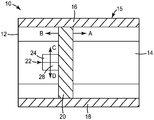
도 1을 참조하면, 플라잉 옵틱(비-주사) 레이저 처리 시스템(10)은 플로어와 같은 안정된 표면에 장착되는 고정된 편평한 테이블(12)을 포함한다. 공작물(14)은 테이블(12) 상에 안착되거나, 방향 A를 따라 테이블(12)을 가로질러 이동한다. 강성의 캔트리(gantry)형 기구(15)가 테이블(12) 상에 장착되는데, 이는 평행 레일 부재들(16, 18) 내에서 방향 A 및 B를 따라 이동하는 가로대(20)를 포함한다. 레이저 헤드 유닛(22)은 가로대(20)를 따라 방향 C 및 D로 이동한다. 레이저 빔은 광학 트레인(24)에 의해 레일 부재들(16, 18)을 따라 레이저 헤드 유닛(22)에 레이저(도시되지 않음)로 전달된다. 레이저 헤드 유닛(22)에 의해 전달되는 빔의 배향이 고정되어 있기 때문에, 평행 레일 부재들(16, 18)은 비교적 큰 거리에 걸쳐 가로대(20) 및/또는 레이저 헤드 유닛(22)을 신속하게 이동시킬 수 있어야 된다. 평행 레일 부재들(16, 18) 및 가로대(20)는 공작물(14) 위에서 레이저 헤드 유닛(22)을 신속하고 정확하게 이동시키기 위해 강성이어야 하며, 이와 같이 해서 테이블(12)의 크기 및 처리될 공작물(14)의 면적에 따라 부피가 크고 질량이 비례한다. 레이저 빔을 가속시키고 그리고/또는 그의 방향을 변화시키기 위해서는 갠트리 기구(15) 및 레이저 헤드 유닛(22)의 구성요소들의 상당한 관성이 극복되어야 한다. 비-주사 레이저 시스템(10)의 설계에서, 종종 레이저 헤드 유닛(22) 및 공작물(14)이 상대적으로 서로에 밀접한 경우가 있는데, 이는 시스템(10)의 잠재적인 최종 사용들을 제한한다.Referring to FIG. 1, a flying optics (non-scanning)
비-주사 시스템(10)에서, 레이저 헤드 유닛(22) 및 공작물(14)이 함께 밀접하게 위치될 수 있기 때문에 공작물(14) 상의 레이저 스폿 근방에 처리 기능을 추가하는 것은 상대적으로 간단하다. 예를 들어, 레이저 커팅에 이어서 공작물(14)로부터 떨어진 잔해물을 관리하기 위해, 레이저 헤드 유닛(22)은 진공 시스템 또는 압축 공기원에 부착되는 노즐(28)을 포함할 수 있다. 그러나, 노즐(28)과 같은 추가적인 처리 설비는 또한 레이저 헤드 유닛(22)의 질량에 부가되는데, 이는 레이저 빔을 가속시키고 그리고/또는 그의 방향을 변화시키는 능력을 추가로 제한한다.In the
도 2의 주사 레이저 시스템(30)은 플로어와 같은 안정된 표면에 고정식으로 장착되는 고정된 편평한 공작물 취급 표면(32)을 포함한다. 공작물(34)은 표면(32) 상에 안착되거나, 방향 A를 따라 표면(32)을 가로질러 이동한다. 레이저 헤드 유닛(36)은 테이블(32) 및 공작물(34)에 대해 고정될 수 있거나, 또는 이동가능할 수 있다. 레이저 빔(38)은 레이저 헤드 유닛(36)에 레이저(도 2에 도시되지 않음)로 전달되며, 검류계 주사 유닛(41)의 부품을 형성하는 작은 미러들(42, 44)의 배열체를 횡단한다. 검류계 주사 유닛(41)은 임의의 수의 미러들(42, 44)뿐만 아니라 특정 응용을 위해 요구되는 바와 같은 포커싱 광학기기를 포함할 수 있으며, 도 2에 도시된 배열은 단지 사용될 수 있는 하나의 설계의 일례이다. 검류계 주사 유닛(41) 내의 미러들(42, 44)은 샤프트들(50, 52)을 거쳐 모터들(46, 48)에 부착된다. 미러(42)는 모터(46)에 의해 각도 θ1에 걸쳐 회전되며, 미러(44)는 모터(48)에 의해 각도 θ2에 걸쳐 회전된다. 미러들(42, 44)의 이동은 조향된 레이저 빔(40)을 공작물(34)의 여기저기로 조향한다. 미러들(42, 44)이 작고 경량이기 때문에, 이들 부품들을 신속하고 정확하게 이동시켜 조향된 레이저 빔(40)을 조작하기 위해서는 비교적 작은 관성이 극복되어야 하며, 조향된 빔(40)은 신속하게 가속되고 공작물(34) 상의 처리되는 영역(55) 내에 정확하게 배치될 수 있다.The
주사 레이저 처리 시스템(30)에서, 레이저 헤드 유닛(36)과 공작물(34) 사이의 작업 거리는 도 1의 비-주사 시스템(10)에서의 레이저 헤드 유닛(22)과 공작물(14) 사이의 작업 거리에 비해 비교적 크다.In the scanning
도 2에서의 시스템(30)과 같은 주사 레이저 처리 시스템들은 많은 바람직한 특성들(높은 동적 성능, 증가된 작업 거리들, 및 큰 처리 영역)을 갖지만, 추가적인 처리 기능들을 처리된 영역(55)에서 수행하기가 어려울 수 있다. 예를 들어, 주사 시스템(30) 상의 잔해물 관리는 공기 또는 물을 전달하는 유체 공급 장치(60)를 포함할 수 있어 배출된 입자를 처리된 영역(55)으로부터 진공 시스템(62) 내로 이동시킬 수 있게 하며, 이는 배출된 입자가 공작물(34) 상에 정착되지 않게 하고 레이저 전송에 간섭하지 않게 한다. 이러한 전반적인 처리 방법들의 효과는 레이저 헤드 유닛(36)과 공작물(34) 사이의 큰 작업 거리에 의해 제한되는데, 이는 궁극적으로 레이저 처리에서 초래되어 처리된 부품들 상에 정착되고 그리고/또는 이들을 얼룩지게 하는 임의의 오염물에 대해 더 큰 기회를 제공한다.Scanning laser processing systems, such as
본 발명에 기술된 주사 레이저 시스템은 공작물의 처리된 영역에 대해 국소적인(근위의(proximal)) 추가의 처리 기능을 수행하도록 선택된 저관성 엔드 이펙터로 공작물의 원위의(distal) 레이저 헤드 유닛에 의해 조향된 레이저 빔을 추적할 수 있게 해준다. 저관성 엔드 이펙터를 사용하는 처리된 영역에서의 국소 처리 능력과 조합된, 레이저 주사 시스템에 의해 제공되는 처리된 영역으로의 고도로 동적인 빔 전달은 처리 속도에 대한 영향을 최소로 하면서 신속하고 정확한 공작물 처리를 원하는 경우에 중요할 수 있다. 예를 들어, 주사된 레이저 빔을 추적하는 저관성 노즐은 레이저가 공작물의 여기저기로 이동함에 따라 처리된 영역에 공기 또는 진공을 전달할 수 있다. 이러한 국소화된 잔해물 관리는 레이저에 의해 공작물로부터 떨어진 입자를 보다 효과적으로 제거할 수 있으며, 이는 디스플레이 패널, 광학 필름, 테이프 등과 같은 민감성 제품에 대한 품질을 개선할 수 있다.The scanning laser system described in the present invention is a low inertia end effector selected to perform a local (proximal) further processing function on the processed region of the workpiece by the distal laser head unit of the workpiece Allows tracking of the steered laser beam. Highly dynamic beam delivery to the processed region provided by the laser scanning system, combined with local processing capability in the processed region using a low inertia end effector, allows fast and accurate workpiece < RTI ID = 0.0 > It can be important if processing is desired. For example, a low inertia nozzle that tracks the scanned laser beam can deliver air or vacuum to the treated region as the laser moves around the workpiece. Such localized debris management can more effectively remove particles away from the workpiece by the laser, which can improve the quality of sensitive products such as display panels, optical films, tapes, and the like.
도 3은 플로어와 같은 안정된 표면에 고정식으로 장착되는 고정된 편평한 공작물 취급 표면(102)을 포함하는 주사 레이저 재료 처리 시스템(100)의 일 실시 형태를 도시한다. 공작물(104)은 공작물 취급 표면(102) 상에 안착되거나, 방향 A를 따라 공작물 취급 표면(102)을 가로질러 이동한다. 레이저 헤드 유닛(106)은 공작물 취급 표면(102) 및 공작물(104)에 대해 고정될 수 있거나, 또는 이동가능할 수 있다. 레이저 빔(108)은 레이저 헤드 유닛(106)에 레이저(도시되지 않음)로 전달된다.Figure 3 illustrates one embodiment of a scanning laser
검류계 주사 유닛(141)은 레이저 빔(108)을 조향하기 위해 이동될 수 있는 전동식 미러들의 배열체를 포함한다. 검류계 주사 유닛(141)은 임의의 수의 미러들뿐만 아니라 특정 응용을 위해 요구되는 포커싱 광학기기를 포함할 수 있으며, 도 3에 개략적으로 도시된 배열은 단지 사용될 수 있는 하나의 설계의 일례이다. 검류계 주사 유닛(141) 내의 미러들(142, 144)은 샤프트들(150, 152)을 거쳐 모터들(146, 148)에 부착된다. 미러(142)는 모터(146)에 의해 각도 θ1에 걸쳐 회전되며, 미러(144)는 모터(148)에 의해 각도 θ2에 걸쳐 회전된다. 그에 따라, 미러들(142, 144)의 이동은 조향된 레이저 빔(110)을 공작물(104)의 여기저기로 지향시키는 데 사용될 수 있다. 미러들(142, 144)이 작고 경량이기 때문에, 이들 부품들을 신속하고 정확하게 이동시켜 레이저 빔(110)을 조향하기 위해서는 비교적 작은 관성이 극복되어야 하며, 조향된 빔(110)은 신속하게 가속되고 공작물(104) 상의 처리되는 영역(155) 내에 정확하게 배치될 수 있다.The
시스템(100)은 로봇 조작기(170)에 의해 공작물(104)에 대해 이동되는 엔드 이펙터(160)를 추가로 포함한다. 이러한 실시 형태에서, 로봇 조작기는 세 개의 축을 포함하는 델타형 로봇이며, 엔드 이펙터(160)가 최대 3의 자유도를 갖도록 공작물(104)에 대해 x, y 및 z 방향 중 임의의 방향으로 엔드 이펙터(160)를 이동시키도록 구성될 수 있다.The
도 3의 실시 형태에서, 로봇 조작기(170)는 고정 기부(172), 및 상부 아암들(174)의 배열체를 포함하는데, 이들 상부 아암 각각은 고정 기부(172) 상의 가요성 조인트(173)에 부착되는 제1 단부(174A)를 갖는다. 상부 아암들(174) 각각은 엘보우 조인트(176)에 부착되는 제2 단부(174B)를 구비하는데, 이는 이어서 하부 아암(178)의 제1 단부(178A)에 연결된다. 하부 아암들(178) 각각의 제2 단부(178B)는 엔드 이펙터(160)에 연결된다.In the embodiment of Figure 3, the
조향된 레이저 빔(110)이 공작물(104) 상의 처리되는 영역(155)의 여기저기로 이동하고, 커팅, 드릴링, 스크라이빙, 머시닝 등에 의해 공작물(104)을 처리함에 따라, 엔드 이펙터(160)는 레이저 빔이 공작물(104) 상에 입사되는 위치(156)를 사전결정된 스탠드오프 거리 d 내에서 추적한다. 사전결정된 스탠드오프 거리 d는 엔드 이펙터(160)의 의도된 응용에 따라 광범위하게 변할 수 있지만, 일부 실시 형태에서, 엔드 이펙터(160)는 항상 레이저 스폿(156)의 약 ±100 밀리미터(mm)의 스탠드오프 거리 d 내에 있다. 다른 실시 형태에서, d는 레이저 스폿(156)의 ±5 mm 이내이거나, 또는 레이저 스폿(156)의 ±0.1 mm 이내이다.As the steered
엔드 이펙터(160)는 레이저 스폿(156)에 인접한 영역에서 의도된 처리 응용에 따라 광범위하게 변할 수 있다. 엔드 이펙터(160)는 충분히 낮은 질량을 갖는 임의의 유형의 장치로부터 선택될 수 있어서, 로봇 조작기(170)가 요구되는 처리 영역(155)에 걸쳐 특정 응용을 위해 필요로 하는 스탠드오프 거리(예컨대, 전술된 바와 같은 ±100 mm)로 공작물(104) 상의 레이저 스폿(156)을 추적하도록 엔드 이펙터(160)를 신속하게 이동시킬 수 있게 한다. 예를 들어, 엔드 이펙터(160)에 의해 액세스가능한 처리 영역(155)은 전형적으로 약 50 × 50 mm 내지 약 500 × 500 mm이지만(여기서, 잔해물은 250 × 250 mm 내지 500 × 500 mm 범위에서 오히려 문제가 됨), 많은 다른 크기들이 가능하다. 엔드 이펙터(160)는, 엔드 이펙터(160)가 로봇 조작기(170)에 의해 초 당 최대 150 m/s의 속도로 가속될 수 있도록 충분히 낮은 질량을 가져야 한다. 엔드 이펙터(160)는 전형적으로 처리된 영역(155) 내에서 약 1 m/s 내지 약 5 m/s의 속도로 이동하는데, 이는 제조 세팅에서 동작들을 전환하는 데 매우 유용하다.The
엔드 이펙터(160)는 적절하게 가요성인 케이블, 튜브, 광섬유, 배선 또는 이들의 조합(180)을 통해 공급원(182)에 선택적으로 연결될 수 있다. 공급원(182)은 예를 들어 하기 중 임의의 것 또는 전부로부터 선택될 수 있다: 진공 펌프, 공기, 불활성 가스, 또는 물과 같은 가압 유체원, 공작물의 표면 상의 소결하기 위한 분말 합금 혼합물과 같은 고형 반응물 공급원, 공작물을 제조하는 재료와 반응하는 액체 화학물질(또는 공작물의 표면 상에 있는 다른 화학물질)의 공급원, 또는 공작물의 표면 상에 화학 반응(예컨대, 경화)을 야기하는 자외선(UV)과 같은 방사선원.The
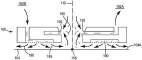
예를 들어, 잔해물 관리에 적합한 실시 형태에서, 도 4의 엔드 이펙터(160)는 가요성 튜브(180)(도 3)를 거쳐 공급원(182)에 연결되는 노즐인데, 이 공급원은 진공원(182A), 및 가압 유체원(182B), 예컨대 공기, 불활성 가스 또는 물을 포함한다. 이러한 실시 형태에서, 레이저 빔(110)은 공작물 표면(104A)을 처리하고, 입자 및 연기(185)를 포함하는 잔해물 기둥(plume)을 생성한다. 입자 및 연기(185)는 표면(104A) 근처에서 레이저 빔(110)의 전송을 변경할 수 있고, 잠재적으로 연소를 야기할 수 있으며, 처리된 제품의 품질에 악영향을 줄 수 있다. 표면(104A)으로부터 입자 및 연기(185)를 사실상 계속적으로 제거하기 위해서, 엔드 이펙터(160)는 가압 유체를 유체 공급부(182B)로부터 표면(104A) 상으로 지향시키는 유체 공급 노즐부(190)를 포함한다. 유체 공급 노즐부(190)로부터의 가압 유체의 유동은 입자 및 연기(185)를 표면(104A)으로부터 떨어지게 한다. 이어서, 떨어진 입자 및 연기(185)는 진공원(182A)으로부터의 진공 스트림 내에 연행되고, 진공 노즐(192)의 배열체를 거쳐 표면(104A)으로부터 제거된다.For example, in an embodiment suitable for debris management, the
전술된 바와 같이, 도 4에 전술된 특정 잔해물 관리 실시 형태에 부가하여, 엔드 이펙터(160)는 예를 들어, 카메라 또는 다른 렌즈 시스템과 같은 광학 요소, 처리 중에 공작물의 검사를 위한 센서, 방사선 방출기, 고체 또는 액체 재료 분배기, 및 이들의 조합으로부터 선택될 수 있다. 본 명세서에 기술된 엔드 이펙터는 공작물의 레이저 전환과 특히 잘 작업하며, 대개 이동 웨브 라인 및 온라인 처리와 같은 제한된 공간에서 유리하도록 사용될 수 있다. 그러나, 본 명세서에 기술된 낮은 질량의 고속 엔드 이펙터들은 능동적인 국소적 운동(커팅, 가열, 진공처리 등), 또는 수동적인 국소적 운동(시각적 검사, 공정 모니터링 등), 또는 양자의 조합을 비롯한 고속 국소적 운동으로부터 이익을 얻을 수 있는 임의의 응용에서 사용될 수 있다.As discussed above, in addition to the particular debris management embodiment described above in FIG. 4, the
도 5는 플로어와 같은 안정된 표면에 고정식으로 장착되는 고정된 편평한 공작물 취급 표면(202)을 포함하는 주사 레이저 재료 처리 시스템(200)의 다른 실시 형태의 개략도이다. 공작물(204)은 공작물 취급 표면(202) 상에 안착되고, 방향 A를 따라 공작물 취급 표면(202)을 가로질러 이동한다. 레이저 헤드 유닛(206)은 공작물 취급 표면(202) 및 공작물(204)에 대해 고정될 수 있거나, 또는 이동가능할 수 있다. 레이저 빔(208)은 레이저 헤드 유닛(206)에 레이저(도시되지 않음)로 전달된다.5 is a schematic diagram of another embodiment of a scanning laser
검류계 주사 유닛(241)은 레이저 빔(208)을 조향하기 위해 이동될 수 있는 전동식 미러들의 배열체를 포함한다. 검류계 주사 유닛(241)은 임의의 수의 미러들뿐만 아니라 특정 응용을 위해 요구되는 바와 같은 포커싱 광학기기를 포함할 수 있으며, 도 5에 개략적으로 도시된 배열은 단지 사용될 수 있는 하나의 설계의 일례이다. 검류계 주사 유닛(241) 내의 미러들(242, 244)은 샤프트들(250, 252)을 거쳐 모터들(246, 248)에 부착된다. 미러(242)는 모터(246)에 의해 각도 θ1에 걸쳐 회전되며, 미러(244)는 모터(248)에 의해 각도 θ2에 걸쳐 회전된다. 그에 따라, 미러들(242, 244)의 이동은 조향된 레이저 빔(210)을 공작물(204)의 여기저기로 지향시키는 데 사용될 수 있다. 미러들(242, 244)이 작고 경량이기 때문에, 이들 부품들을 신속하고 정확하게 이동시켜 조향된 레이저 빔(210)을 지향시키기 위해서는 비교적 작은 관성이 극복되어야 하며, 조향된 빔(210)은 신속하게 가속되어 공작물(204) 상의 처리되는 영역(255) 내에 정확하게 배치될 수 있다.The
시스템(200)은 로봇 조작기(270)에 의해 공작물(204)에 대해 이동되는 엔드 이펙터(260)를 추가로 포함한다. 이러한 실시 형태에서, 로봇 조작기(270)는 복수의 인장된 케이블(272)에 의해 조작되는 케이블 로봇이다. 케이블(272)에서의 상대 인장력을 변경함으로써, 엔드 이펙터(260)의 위치, 속도, 및 가속도는 공작물(204) 상의 레이저 빔 스폿(256)을 추적하도록 정확하게 제어될 수 있다. 로봇 조작기(270)의 케이블-현가형 형태(morphology)는 로봇 조작기(270)의 관성을 단지 현가 케이블(272) 및 작동기 내부기기(도시되지 않음)의 관성까지 추가로 감소시켜, 로봇 조작기(270)가 도 3의 로봇 조작기(170)보다 더 낮은 관성을 갖게 한다. 케이블 로봇(270)은 임의의 수의 케이블(272)을 포함할 수 있으며, 도 5의 예에서는 네 개의 케이블을 포함하고 엔드 이펙터(260)의 이동에 대해 3의 자유도를 제공한다. 7개의 케이블(272)을 사용하면, 로봇(270)은 최대 6의 자유도를 가질 수 있고, 공작물(204)에 대해 x, y 및 z 방향 중 임의의 방향으로 (그리고, 회전식으로) 엔드 이펙터(260)를 이동시키도록 구성될 수 있다.The
도 5의 실시 형태에서, 케이블(272) 각각은 엔드 이펙터(260)에 부착되는 제1 단부(272A) 및 케이블 제어 기구(275)에 부착되는 제2 단부(272B)를 포함한다. 도 6은 단일 케이블(272)을 위한 케이블 제어 기구(275)의 일례를 도시한다. 케이블(272)의 인장력 및 유효 길이를 제어하는 케이블 제어 기구는 윈치 드럼(278)이 그 위에 장착되는 출력 샤프트를 갖는 모터(276)를 포함한다. 윈치 드럼(278)은 케이블(272)의 제2 단부(272B)와 결합된다. 인장 로드셀(284) 및 안내 풀리(286) 주위를 통과한 후, 케이블(272)의 제1 단부(272A)는 엔드 이펙터(260)에 연결된다.5, each of the
이러한 설계를 사용하면, 엔드 이펙터(260)는 공작물(204)과 접촉 상태로 되는 것이 아니라, 케이블 제어 기구(275)에 의해 케이블(272)에 유지되는 인장력을 통해 처리 영역(255) 위에 현가된다. 엔드 이펙터(260) 상에 작용하는 중력으로 인한 케이블(272)에서의 임의의 처짐은 엔드 이펙터(260)를 가요성 튜브(280)에 연결함으로써 선택적으로 감소 및/또는 제거될 수 있으며, 이어서 가요성 튜브는 공기와 같은 가압 가스의 공급원(282)에 연결된다. 이어서, 엔드 이펙터는 엔드 이펙터(260)를 빠져나가는 가압 가스를 공기 베어링으로서 이용하여 엔드 이펙터(260)를 처리 영역(255) 위에 유지되게 할 수 있다.Using this design, the
조향된 레이저 빔(210)이 공작물(204) 상의 처리된 영역(255)의 여기저기로 이동하고, 커팅, 드릴링, 스크라이빙, 머시닝, 등에 의해 공작물(204)을 처리함에 따라, 엔드 이펙터(260)는 레이저 빔이 공작물(204) 상에 입사되는 위치(256)를 사전결정된 스탠드오프 거리 d 내에서 추적한다. 사전결정된 스탠드오프 거리 d는 엔드 이펙터(260)의 의도된 응용에 따라 광범위하게 변할 수 있지만, 일부 실시 형태에서, 엔드 이펙터(260)는 항상 레이저 스폿(256)의 약 ±100 밀리미터(mm)의 스탠드오프 거리 d 내에 있다. 다른 실시 형태에서, d는 레이저 스폿(256)의 ±5 mm 이내이거나, 또는 레이저 스폿(256)의 ±0.1 mm 이내이다.As the steered
엔드 이펙터(260)는 의도된 응용에 따라 광범위하게 변할 수 있으며, 충분히 낮은 질량을 갖는 임의의 유형의 장치로부터 선택될 수 있어서, 로봇 조작기(270)가 요구되는 처리 영역(255)에 걸쳐 특정 응용을 위해 필요로 하는 스탠드오프 거리(예컨대, 전술된 바와 같은 ±100 mm)로 공작물(204) 상의 레이저 스폿(256)을 추적하도록 엔드 이펙터(260)를 신속하게 이동시킬 수 있게 한다. 예를 들어, 케이블-현가형 로봇(270)을 사용하는 엔드 이펙터(260)에 의해 액세스가능한 처리 영역(255)은 전형적으로 약 50 × 50 mm 내지 약 500 × 500 mm이지만, 많은 다른 크기들이 가능하다. 엔드 이펙터(260)는, 엔드 이펙터(260)가 약 5 m/s 이상의 속도에 도달하여 로봇 조작기(270)에 의해 초 당 최대 200 m/s의 속도(중력 G의 20배)로 가속될 수 있도록 충분히 낮은 질량을 가져야 한다.The
엔드 이펙터(260)는 가요성 케이블, 튜브, 광섬유, 배선 또는 이들의 조합(280)을 거쳐 공급원(282)에 선택적으로 연결될 수 있다. 공급원(282)은 예를 들어 하기 중 임의의 것 또는 전부로부터 선택될 수 있다: 진공 펌프, 공기, 불활성 가스, 또는 물과 같은 가압 유체원, 공작물의 표면 상의 소결하기 위한 분말 합금 혼합물과 같은 고형 반응물 공급원, 공작물을 제조하는 재료와 반응하는 액체 화학물질(또는 공작물의 표면 상에 있는 다른 화학물질)의 공급원, 또는 공작물의 표면 상에 화학 반응(예컨대, 경화)을 야기하는 자외선(UV)과 같은 방사원.The
도 4에 전술된 특정 잔해물 관리 실시 형태에 부가하여, 엔드 이펙터(260)는 예를 들어, 카메라 또는 다른 렌즈 시스템과 같은 광학 요소, 처리 중에 공작물의 검사를 위한 센서, 방사선 방출기, 고체 또는 액체 재료 분배기 및 이들의 조합으로부터 선택될 수 있다. 본 명세서에 기술된 엔드 이펙터(260)는 공작물의 레이저 전환과 특히 잘 작업하며, 대개 이동 웨브 라인 및 온라인 처리와 같은 제한된 공간에서 유리하도록 사용될 수 있다. 그러나, 낮은 질량의 고속 엔드 이펙터들은 능동적인 국소적 운동(커팅, 가열, 진공처리 등) 또는 수동적인 국소적 운동(시각적 검사, 공정 모니터링 등), 또는 양자의 조합을 비롯한 고속 국소적 운동으로부터 이익을 얻을 수 있는 임의의 응용에서 사용될 수 있다.In addition to the particular debris management embodiment described above in FIG. 4, the
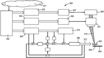
도 7은 엔드 이펙터(360)가 공작물(304)의 표면 위에서 레이저 빔(310)의 이동을 추적하게 하도록 구성된 프로세서를 포함하는 제어 유닛(300)의 일 실시 형태를 도시하는 개략적인 흐름도이다(도 5 및 도 6도 또한 참조). 공작물(304)에 대한 레이저 빔(310)의 이동을 제어하기 위해, 조작자는 초기에 궤적 파라미터(301)와 함께 레이저 궤적 데이터를 공작물(304) 상의, 그 위의, 또는 그 아래의 위치에서의 공작물 좌표의 형태로 제어 유닛(300) 내로 입력한다. 제어 유닛(300)은 궤적 생성 모듈(302)을 포함하는데, 이 궤적 생성 모듈(302)은 레이저 궤적 및 파라미터(301)에 기초하여, 레이저 제어 모듈(303)을 위한 전력 신호, 레이저 헤드 유닛 제어 모듈(304)을 위한 궤적 데이터, 및 로봇 조작기 제어 모듈(306)에 대한 로봇 위치 데이터를 생성한다.7 is a schematic flow diagram illustrating one embodiment of a
레이저 제어 모듈(303)은 레이저 제어기(307)에 레이저 제어 신호를 제공하여 레이저(309)에 전력을 공급한다. 레이저 헤드 유닛 제어 모듈(304)은 레이저 헤드 유닛 제어기(308)에 레이저 헤드 유닛 제어 신호를 검류계(341) 내의 미러 어레이를 위한 회전 위치 데이터로서 제공하며, 이는, 이어서, 레이저(309)에 의해 방출되는 조향된 레이저 빔(310)의 공작물(304)에 관한 궤적을 제어한다.The
로봇 조작기 제어 모듈(306)에 의해 제공되는 로봇 위치 데이터는, 예를 들어, (도 5 및 도 6의) 윈치 드럼을 위한 각도 위치 데이터 및 로봇 조작기의 케이블을 위한 인장력 데이터를 포함한다. 로봇 조작기 제어 모듈(306)은 인장 로드셀(384) 및 케이블(372)의 배열체를 제어하는 케이블 기구(375)를 활성화한다. 예를 들어, 일부 실시 형태에서, 로봇 위치 데이터는 윈치 드럼 각도(및 그에 따라 유효 케이블 길이)에 대응하는 회전 데이터로서 케이블 기구(375)에 제공될 수 있다. 이러한 신호들은 각각의 인장 로드셀(384)로의 입력을 위한 위치 피드백에 기초하여 토크 데이터로 전환될 수 있다. 상기는 각각의 케이블에 적절한 상대 인장력을 가져와서, 투여된 아트워크(imported artwork) 및 파라미터(301)에 의해 특정되는 바와 같은 공작물(304)에 대한 위치(356)에 엔드 이펙터(360)를 위치시킨다.The robot position data provided by the robot
레이저 헤드 유닛 제어 신호 및 로봇 조작기 제어 신호가 제어기(300) 내의 프로세서에 의해 조정(coordinate)되어서, 엔드 이펙터(360)는 레이저 빔(310)이 공작물(304) 상에 입사되는 위치(356)로부터 사전결정된 스탠드오프 거리 d(도 5) 내에서 조향된 레이저 빔(310)의 이동을 추적하게 된다.The laser head unit control signal and the robot manipulator control signal are coordinated by the processor within the
레이저 헤드 유닛 제어 신호 및 로봇 조작기 제어 신호는, 하나 이상의 하드웨어 마이크로프로세서, 디지털 신호 프로세서(DSP), 사용자 주문형 반도체(application specific integrated circuit, ASIC), 필드 프로그램가능 게이트 어레이(field programmable gate array, FPGA), 또는 임의의 다른 등가의 집적 또는 이산 로직 회로뿐만 아니라, 그러한 컴포넌트들의 임의의 조합을 비롯한, 제어 유닛(300)의 모듈들 중의 하나 이상의 프로세서에 의해 실행되는 소프트웨어 명령어로서 생성될 수 있다. 소프트웨어 명령어는 랜덤 액세스 메모리(RAM), 판독 전용 메모리(ROM), 프로그램가능 판독 전용 메모리(PROM), 소거가능 및 프로그램가능 판독 전용 메모리(EPROM), 전자적 소거가능 및 프로그램가능 판독 전용 메모리(EEPROM), 플래시 메모리, 하드 디스크, CD-ROM, 플로피 디스크, 카세트, 자기 매체, 광학 매체, 또는 다른 컴퓨터-판독가능 저장 매체와 같은 비-일시적 컴퓨터 판독가능 매체 내에 저장될 수 있다.The laser head unit control signals and the robot operator control signals may be generated by one or more hardware microprocessors, digital signal processors (DSPs), application specific integrated circuits (ASICs), field programmable gate arrays (FPGAs) , Or any other equivalent integrated or discrete logic circuitry, as well as any combination of such components. The software instructions may be stored in a random access memory (RAM), read only memory (ROM), programmable read only memory (PROM), erasable and programmable read only memory (EPROM), electronically erasable and programmable read only memory (EEPROM) , Flash memory, hard disk, CD-ROM, floppy disk, cassette, magnetic media, optical media, or other computer-readable storage media.
전술된 처리 시스템은 롤-투-롤 제조 공정에서의 웨브 재료의 전환 및 처리에 특히 매우 적합하다. 그러한 공정에서, 공작물은 주사된 레이저에 의해 고속으로 전환되는 재료의 이동 웨브이고, 저관성 엔드 이펙터는 주사된 레이저 빔에 의해 전환되는 영역을 추가로 처리하는 데 사용될 수 있다. 예를 들어, 본 명세서에 기술된 저관성 재료 처리 시스템은 레이저 처리를 통한 정확한 전환으로부터 이익을 얻을 수 있는(또는 정확한 전환을 필요로 하는) 임의의 그러한 고처리량(high throughput) 공정에서 유용할 수 있다. 특히, 본 명세서 내의 저관성 재료 처리 시스템은, 예를 들어, LCD 패널, 낙서 방지 필름, 및 테이프와 같은 최종 제품의 광학 품질이 중요시되는 잔해물-감지 필름 제품의 정확한 레이저 전환에 유용하다.The above-described treatment systems are particularly well suited for the conversion and treatment of web materials in roll-to-roll manufacturing processes. In such a process, the workpiece is a moving web of material that is rapidly switched by the scanned laser, and the low inertia end effector can be used to further process the area being switched by the scanned laser beam. For example, the low inertia material processing system described herein may be useful in any such high throughput process that can benefit from accurate conversion through laser processing (or that requires accurate conversion) have. In particular, the low inertia material processing system herein is useful for accurate laser conversion of a debris-sensing film product where optical quality of the final product, such as, for example, LCD panels, anti-graffiti films,
도 7의 제어기(300)는 제조 설비의 내부에 위치될 수 있거나, 또는 제조 설비의 외부에 위치될 수 있거나, 또는 양자의 조합, 예컨대 중앙 위치 또는 전환 구역에 위치될 수 있다. 기술된 구성요소는 단일 컴퓨팅 플랫폼 상에서 실행될 수 있거나, 또는 동일한 소프트웨어 시스템 내에 통합될 수 있다.The
실시예Example
도 5에 도시된 바와 같은 2-축 레이저 주사 헤드 및 3 자유도 케이블-현가형 로봇을 사용하여 저관성 레이저 주사 및 엔드 이펙터 운동을 갖는 재료 처리 시스템을 구성했다. 표 1은 하기에 기술되는 실시예를 구성하는 데 사용되는 상업적으로 입수가능한 설비의 목록을 제공한다.A material processing system having low inertia laser scanning and end effector motion was constructed using a two-axis laser scanning head and a three degree of freedom cable-suspension robot as shown in Fig. Table 1 provides a list of commercially available equipment used to construct the embodiments described below.
[표 1][Table 1]

표 1에 열거된 레이저 주사 헤드를 필드 크기가 140 × 140 mm로 되는 204 mm 작업 거리 렌즈에 장착했다. 표 1에 포함된 전자기기, 모터, 및 드라이브를 사용하여 케이블-현가형 로봇을 주문 구축하였다. 엔드 이펙터 작업 공간이 대략 1.2 미터 × 0.6 미터로 되는 1.4 × 0.83 미터 직사각형의 코너에 안내 풀리(286)를 위치시킨 직사각형 배열로 네 개의 케이블 안내 조립체들(인장 로드셀들(284) 및 안내 풀리들(286), 도 6)을 장착하였다.The laser scanning heads listed in Table 1 were mounted on a 204 mm working distance lens with a field size of 140 x 140 mm. The cable-suspension robot was custom-built using the electronics, motors, and drives included in Table 1. The four cable guide assemblies (
도 7에 개요를 나타낸 방식에 의해 재료 처리 시스템을 제어하였다. 로컬 호스트 PC와 표 1에 열거된 매립형 제어기 사이에 제어 유닛(300)의 컴포넌트들을 분포시켰는데, 이때, 로컬 호스트 PC와 매립형 제어기는 이더넷을 통해 접속되었다. 로컬 호스트 개인용 컴퓨터(PC) 상에 레이저 제어 모듈(303), 레이저 헤드 유닛 제어 모듈(304), 로봇 조작기 제어 모듈(306)을 구현하였다. 입수가능한 FPGA 리소스들을 활용하여 매립형 제어기 상에 레이저 제어기(307) 및 레이저 헤드 유닛 제어기(308)를 구현하였다.The material processing system was controlled by the scheme outlined in Fig. The components of the
호스트 PC 상의 모듈들(303, 304, 306)을 거쳐 오프라인으로 제어기들(307, 308)에 대한 설정점들을 계산했다. 특정된 궤적이 주어지면, 궤적 생성 모듈(302)에 의해 레이저 스폿 위치(356) 및 엔드 이펙터 노즐(360)의 위치에 대해 직교 좌표가 생성되었다. 궤적 생성 모듈(302)은 또한, 모든 필요한 지연들 및 오프셋들을 고려하여, 레이저 제어기(307)로 전송하기 위한 대응하는 레이저 제어 신호들(즉, 와트 단위의 레이저 출력 전력)을 레이저 제어 모듈(303)에 제공했다.The set points for the
이어서, 검류계(341) 및 엔드 이펙터(360)에 대한 직교 좌표를 각각 레이저 헤드 유닛 제어 모듈(304) 및 로봇 조작기 제어 모듈(306)로 보냈고, 검류계(341) 및 케이블 제어기(375)의 네이티브 좌표계(native coordinate system)로 변환했다. 이러한 네이티브 좌표는 케이블 제어기(375)에 대한 검류계(341) 및 윈치 드럼의 회전을 위한 미러 각도를 설명한다. 각각의 설정점에 대해, 특정된 최소 케이블 인장력뿐만 아니라 로봇의 물리적 특성 및 엔드 이펙터(360)의 위치에 의해 결정되는 시스템의 구조 매트릭스에 기초하여, 로봇 조작기 제어 모듈(306)에 의해 대응하는 최적의 인장력들을 계산했다. 본 발명자들은 기술된 실시예의 설정 및 예상되는 동적 성능을 고려하면 15 내지 20 N의 최소 인장력 값이 양호한 값임을 발견하였다.Cartesian coordinates of the
전술된 네이티브 궤적 데이터로부터, 표 1에 열거된 매립형 제어기의 FPGA 상에서 가동하는 각각의 제어기들(307, 308, 375)에 의해 적절한 제어 신호들을 생성했다. 레이저 제어기(307)는 궤적 전력 데이터를 취하고, 대응하는 TTL 파형을 생성하여 레이저 출력을 구동시킨다. 레이저 헤드 유닛 제어기(308)는 계산된 검류계 미러 각도를 XY2-100 스캐너 프로토콜을 통해 검류계 스캐너(341)로 송신하는데; 이러한 신호들은 9401 디지털 I/O 모듈에 의해 생성되었다. 케이블 제어기(375)는 (토크로서의) 최적의 인장력뿐만 아니라 원하는 윈치 각도 위치를 받아서, 모터 엔코더로부터의 피드백을 고려하면서 표 1에 열거된 모터 드라이브를 이용하여 적절한 토크 값을 인장 로드셀(384)로 송신한다. 케이블 제어기(375)에 의해 모든 토크 커맨드를 9516 드라이브 인터페이스 모듈을 거쳐 인장 로드셀(384)로 송신했다.From the above-described native trajectory data, appropriate control signals were generated by the
2 ㎑ 업데이트 레이트로 되는 0.5 밀리초 시간 스텝들로 모든 궤적 데이터(설정점, 레이저 제어, 및 최적 인장력)를 생성했다. 레이저 제어기(307), 검류계 제어기(308), 케이블 제어기(375)를 20 ㎑로 가동하였다.Laser control, and optimal tensile force) with 0.5 millisecond time steps at a 2 kHz update rate. The
실행된 경로는 작업 공간 기점(origin)에 중심이 맞추어진 40 밀리미터 정사각형으로 구성하였다. 경로는 기점에서 시작해서 x-축을 따라 음으로 그리고 y-축을 따라 양으로 상부좌측 코너로 이동한 다음, y-축을 따라 음으로 하부좌측 코너로, 이어서 x-축을 따라 양으로 하부우측 코너로, 이어서 y-축을 따라 양으로 상부우측 코너로, 이어서 x-축을 따라 음으로 다시 상부좌측 코너로, 이어서 마지막으로 다시 기점으로 이동했다. 궤적 생성 모듈(302)에 의해 생성된 궤적은, 초 당 150 m/s로 제한되고 속도를 최대화하도록 설정되어, 그에 따라 구간적으로(piecewise) 일정한 가속도 프로파일, 연속적인 속도 프로파일, 및 연속적으로 구별가능한 위치 프로파일을 야기하는 가속도였다.The executed path consisted of a 40 millimeter square centered on the origin of the workspace. The path starts from the origin and goes negative along the x-axis and toward the upper left corner along the y-axis and then down to the lower left corner along the y-axis and then to the lower right corner along the x- Followed by an upward positive right-hand corner along the y-axis, followed by a negative left-hand corner along the x-axis, and finally back to the starting point. The locus generated by the
수집된 검류계 스캐너 교정 데이터에 기초한 이중선형 보간법을 이용하여 레이저 헤드 유닛 제어 모듈(304)에 의해 레이저 헤드 유닛 제어기(308)에 대한 입력 좌표를 생성하였다.The input coordinates for the laser
케이블 제어기(375)에 대한 입력을 로봇 조작기 제어 모듈(306)에 의해 생성하였다. 이러한 계산은 케이블 기구를 포함한 기계적 시스템의 기하학적 구조 및 작업공간 내의 그들의 위치로부터 초래되는 상대적인 케이블 길이에 기초하여 이루어졌다.An input to the
케이블 제어기(375)에 의해 제공되는 좌표는 로봇 조작기 제어 모듈(306)에 의해 계산된 최적의 정적 인장력에 의해 보완되었다. 이러한 인장력은 시스템의 구조 매트릭스(그 자체는 엔드 이펙터 위치의 함수임)와 함께, 제공되는 최소 허용 케이블 인장력에 기초하여 계산된다.The coordinates provided by the
엔드 이펙터(360)는 17그램의 질량을 가졌다. 고속 비디오 캡처를 이용하여 시스템의 출력(레이저(309)와 엔드 이펙터(360)의 조합된 동기 운동)을 확인하였다. 교정된 비디오로부터의 실제 직교 좌표가 도 8에 도시되는데, 여기서 x 및 y 축들을 따르는 엔드 이펙터(360)의 위치는 각각 실선 및 파선으로 표현되고; x 및 y 축들을 따르는 레이저 스폿 위치는 각각 일점쇄선 및 점선으로 표현된다. 엔드 이펙터(360)와 레이저 스폿 위치(356) 사이의 상대 위치 오차가 도 9에 도시되는데, 여기서 상대적인 x 및 y 오차들은 각각 파선 및 일점쇄선으로 표현된다. 실선은 궤적의 길이를 따르는 시스템의 총 상대 오차(제곱의 합의 제곱근)를 묘사한다. 이러한 특정 설정으로, 본 발명자들은 궤적의 전체를 따라 3 mm 미만의 상대 오차를 관찰하였다.The
본 발명의 다양한 실시 형태들이 설명되었다. 이들 및 다른 실시 형태는 하기의 특허청구범위의 범주 내에 있게 된다.Various embodiments of the invention have been described. These and other embodiments are within the scope of the following claims.
Claims (56)
상기 로봇 조작기에 의해 작동되며, 공작물에 인접해 있는 엔드 이펙터(end effector);
레이저 및 상기 공작물 위로 레이저 빔을 이동시키도록 구성되는 광학 트레인을 포함하는 주사 레이저 헤드 유닛; 및
상기 엔드 이펙터의 이동이 상기 레이저 빔의 이동을 추적하게 하기 위해 상기 로봇 조작기를 이동시키도록 구성되는 제어 유닛을 포함하는, 장치.A robot manipulator including a fixed base;
An end effector operated by the robot manipulator and adjacent the workpiece;
A scanning laser head unit including a laser and an optical train configured to move the laser beam over the workpiece; And
And a control unit configured to move the robot manipulator to cause movement of the end effector to track movement of the laser beam.
델타형 로봇 및 케이블-현가형 로봇으로부터 선택되며, 고정 기부를 포함하는 로봇 조작기;
상기 로봇 조작기에 부착되고, 공작물의 샘플 영역에 인접해 있으며, 잔해물 관리 장치, 광학 요소, 센서, 방사선 방출기, 및 재료 분배기 중 적어도 하나로부터 선택되는 엔드 이펙터;
상기 엔드 이펙터에 연결되는 엔드 이펙터 공급 시스템;
상기 공작물에 대해 고정되고, 레이저, 및 상기 공작물의 샘플 영역 내의 위치로 레이저 빔을 이동시키도록 구성되는 검류계 스캐너를 포함하는 주사 레이저 헤드 유닛; 및
상기 공작물의 샘플 영역 내의 레이저 빔의 위치로부터 ±5 밀리미터의 거리 이내로 상기 로봇 조작기를 이동시키도록 구성되고, 궤적 생성 모듈을 포함하는 제어 유닛을 포함하고, 상기 궤적 생성 모듈은, 레이저 궤적 및 파라미터에 기초하여, 레이저 제어 모듈이 상기 레이저 빔을 제어하게 하는 전력 신호, 레이저 헤드 유닛 제어 모듈이 상기 주사 레이저 헤드 유닛을 제어하게 하는 궤적 데이터, 및 로봇 조작기 제어 모듈이 상기 로봇 조작기를 작동시키게 하는 로봇 위치 데이터를 생성하는, 시스템.As a system,
A robot manipulator selected from a delta type robot and a cable-suspension type robot and including a fixed base;
An end effector attached to the robot manipulator and proximate to a sample region of the workpiece and selected from at least one of a debris management device, an optical element, a sensor, a radiation emitter, and a material distributor;
An end effector supply system connected to the end effector;
A scanning laser head unit fixed to the workpiece and comprising a galvanometer scanner configured to move the laser beam to a position within the sample region of the workpiece; And
And a control unit including a locus generation module, the locus generation module being configured to move the robot manipulator within a distance of +/- 5 millimeters from a position of the laser beam within a sample area of the workpiece, the locus generation module comprising: Based on the power signal for causing the laser control module to control the laser beam, the locus data for causing the laser head unit control module to control the scanning laser head unit, and the robot position control unit for controlling the robot operation unit System.
레이저, 및 웨브 재료의 표면 위로 레이저 빔을 이동시키도록 구성되는 검류계 스캐너를 포함하는 주사 레이저 헤드 유닛을 상기 웨브 재료 위에 장착하는 단계;
델타형 로봇 및 케이블-현가형 로봇으로부터 선택되고 잔해물 관리 장치가 부착되는 로봇 조작기를 상기 웨브 위에 장착하는 단계; 및
상기 로봇 조작기 및 잔해물 관리 노즐을 이동시켜 상기 레이저 빔을 추적하고 상기 표면으로부터 잔해물을 제거하는 단계를 포함하는, 방법.As a method for managing debris,
Mounting a scanning laser head unit on the web material, the scanning laser head unit including a galvanometer scanner configured to move a laser beam over a surface of the laser and web material;
Mounting a robot manipulator on the web, the robot manipulator being selected from a delta robot and a cable-suspension robot to which a debris management device is attached; And
Moving the robot manipulator and the debris management nozzle to track the laser beam and remove debris from the surface.
상기 재료의 샘플 영역 위로 레이저 빔을 이동시키도록 구성되는 검류계 스캐너를 포함하는 주사 레이저 헤드 유닛을 상기 재료 위에 위치시키는 단계;
상기 샘플 영역 위에 놓이는 엔드 이펙터에 연결되는 로봇 조작기를 상기 재료의 샘플 영역에 인접하게 위치시키는 단계; 및
상기 샘플 영역에서의 상기 레이저 빔의 이동을 ±5 밀리미터의 거리 이내에서 추적하도록 상기 로봇 조작기 및 상기 엔드 이펙터를 제어하는 단계를 포함하는, 방법.A method for processing a sample region of a material in real time as the material is manufactured,
Positioning a scanning laser head unit on the material, the scanning laser head unit including a galvanometer scanner configured to move a laser beam over a sample region of the material;
Positioning a robot manipulator coupled to an end effector overlying the sample region adjacent a sample region of the material; And
And controlling the robot manipulator and the end effector to track movement of the laser beam in the sample region within a distance of +/- 5 millimeters.
델타형 로봇 및 케이블-현가형 로봇으로부터 선택되는 로봇 조작기;
상기 로봇 조작기에 부착되고 상기 웨브 재료의 샘플 영역에 인접해 있는 잔해물 관리 노즐;
상기 잔해물 관리 노즐에 연결되고 진공 및 가압 공기 중 적어도 하나를 제공하는 공급원;
레이저 및 검류계 스캐너를 포함하는 주사 레이저 헤드 유닛; 및
원격 컴퓨터와 통신하며, 엔드 이펙터의 이동이 상기 샘플 영역 내의 상기 레이저 빔의 이동을 추적하게 하기 위해 상기 로봇 조작기를 이동시키도록 구성되는 제어 유닛을 포함하는, 시스템.An on-line computer system for removing debris from a web material when the web material is manufactured,
A robot manipulator selected from a delta type robot and a cable-suspension type robot;
A debris management nozzle attached to the robot manipulator and adjacent a sample region of the web material;
A source connected to the debris management nozzle and providing at least one of vacuum and pressurized air;
A scanning laser head unit including a laser and a galvanometer scanner; And
And a control unit configured to communicate with the remote computer and to move the robot manipulator so that movement of the end effector tracks the movement of the laser beam within the sample region.
상기 프로세서 상에서 실행되는 소프트웨어 프로그램에 의해, 공작물의 표면에 대한 좌표를 포함하는 레이저 궤적 데이터를 수신하게 하는 명령어를 포함하고, 상기 소프트웨어 프로그램은 상기 위치 데이터를:
(a) 표면에 대해 고정되고 상기 표면 위로 레이저 빔을 이동시키도록 구성되는 검류계 스캐너 내의 적어도 하나의 미러의 위치를 나타내는 회전 위치 데이터; 및
(b) 엔드 이펙터에 부착된 로봇 조작기를 구동시키고 상기 엔드 이펙터가 상기 표면 위에서의 상기 레이저 빔의 이동을 추적하게 하는 위치 데이터로 변환하는, 컴퓨터 판독가능 저장 매체.25. A computer-readable storage medium, comprising: one or more processors of a computing device, when executed,
Comprising instructions for causing a software program running on the processor to receive laser locus data comprising coordinates for a surface of a workpiece, the software program comprising:
(a) rotational position data indicative of the position of at least one mirror in a galvanometer scanner configured to be fixed relative to the surface and to move the laser beam onto the surface; And
(b) drives a robot manipulator attached to the end effector and converts the position effect data to position data that allows the end effector to track the movement of the laser beam on the surface.
Applications Claiming Priority (3)
| Application Number | Priority Date | Filing Date | Title |
|---|---|---|---|
| US201261740340P | 2012-12-20 | 2012-12-20 | |
| US61/740,340 | 2012-12-20 | ||
| PCT/US2013/074233 WO2014107274A1 (en) | 2012-12-20 | 2013-12-11 | Material processing low-inertia laser scanning end-effector manipulation |
Related Child Applications (1)
| Application Number | Title | Priority Date | Filing Date |
|---|---|---|---|
| KR1020207031772A Division KR102249405B1 (en) | 2012-12-20 | 2013-12-11 | Material processing low-inertia laser scanning end-effector manipulation |
Publications (1)
| Publication Number | Publication Date |
|---|---|
| KR20150096766A true KR20150096766A (en) | 2015-08-25 |
Family
ID=51062417
Family Applications (2)
| Application Number | Title | Priority Date | Filing Date |
|---|---|---|---|
| KR1020207031772A KR102249405B1 (en) | 2012-12-20 | 2013-12-11 | Material processing low-inertia laser scanning end-effector manipulation |
| KR1020157019370A KR20150096766A (en) | 2012-12-20 | 2013-12-11 | Material processing low-inertia laser scanning end-effector manipulation |
Family Applications Before (1)
| Application Number | Title | Priority Date | Filing Date |
|---|---|---|---|
| KR1020207031772A KR102249405B1 (en) | 2012-12-20 | 2013-12-11 | Material processing low-inertia laser scanning end-effector manipulation |
Country Status (7)
| Country | Link |
|---|---|
| US (1) | US10399178B2 (en) |
| EP (1) | EP2934812B1 (en) |
| JP (1) | JP6382220B2 (en) |
| KR (2) | KR102249405B1 (en) |
| CN (1) | CN104870140B (en) |
| BR (1) | BR112015014893A2 (en) |
| WO (1) | WO2014107274A1 (en) |
Cited By (1)
| Publication number | Priority date | Publication date | Assignee | Title |
|---|---|---|---|---|
| JP2020520836A (en) * | 2017-05-23 | 2020-07-16 | コンサルトエンジニアイーペー アクチェンゲゼルシャフト | Quasi-simultaneous laser welding method |
Families Citing this family (11)
| Publication number | Priority date | Publication date | Assignee | Title |
|---|---|---|---|---|
| US10788836B2 (en) * | 2016-02-29 | 2020-09-29 | AI Incorporated | Obstacle recognition method for autonomous robots |
| JP6035461B1 (en) * | 2016-04-28 | 2016-11-30 | 武井電機工業株式会社 | Laser processing method and laser processing apparatus |
| JP6829053B2 (en) * | 2016-11-09 | 2021-02-10 | コマツ産機株式会社 | Machine room |
| JP6496340B2 (en) * | 2017-03-17 | 2019-04-03 | ファナック株式会社 | Scanner control device, robot control device, and remote laser welding robot system |
| JP6852031B2 (en) * | 2018-09-26 | 2021-03-31 | 株式会社東芝 | Welding equipment and nozzle equipment |
| US20210362287A1 (en) * | 2018-10-25 | 2021-11-25 | 3M Innovative Properties Company | Multiple degree of freedom compliant actuator force control systems and methods used in robotic paint repair |
| IT201900000995A1 (en) * | 2019-01-23 | 2020-07-23 | Nuovo Pignone Tecnologie Srl | INDUSTRIAL ROBOTIC EQUIPMENT WITH IMPROVED PROCESSING PATH GENERATION AND METHOD TO OPERATE INDUSTRIAL ROBOTIC EQUIPMENT ACCORDING TO AN IMPROVED PROCESSING PATH |
| DE102019103659B4 (en) * | 2019-02-13 | 2023-11-30 | Bystronic Laser Ag | Gas guide, laser cutting head and laser cutting machine |
| CN109807475A (en) * | 2019-03-26 | 2019-05-28 | 广西加一米科技有限公司 | Aluminium strip laser Continuous Cutting Machine group |
| CN115555852B (en) * | 2021-06-30 | 2023-06-30 | 宁德时代新能源科技股份有限公司 | Pole piece forming method and device |
| US20230249291A1 (en) * | 2022-02-09 | 2023-08-10 | Ford Global Technologies, Llc | Laser notching apparatus for cutting of electrode sheets |
Family Cites Families (23)
| Publication number | Priority date | Publication date | Assignee | Title |
|---|---|---|---|---|
| JP2915646B2 (en) * | 1991-08-29 | 1999-07-05 | オークマ株式会社 | Sheet metal processing method and machine |
| US5204517A (en) * | 1991-12-24 | 1993-04-20 | Maxwell Laboratories, Inc. | Method and system for control of a material removal process using spectral emission discrimination |
| JP2917763B2 (en) * | 1993-08-11 | 1999-07-12 | 日産自動車株式会社 | Method and apparatus for supplying weld metal powder in overlay welding |
| US6427096B1 (en) | 1999-02-12 | 2002-07-30 | Honeywell International Inc. | Processing tool interface apparatus for use in manufacturing environment |
| US20020104833A1 (en) * | 2001-02-08 | 2002-08-08 | Automated Welding Systems Inc. | Welding head mount for robotic welding apparatus with micro adjustment capability |
| US20040034599A1 (en) | 2001-06-01 | 2004-02-19 | Pietro Ferrero | Method and device for the robot-controlled cutting of workpieces to be assembled by means of laser radiation |
| JP2003181663A (en) * | 2001-12-11 | 2003-07-02 | Mitsubishi Heavy Ind Ltd | Method and head for composite welding |
| DE10204993B4 (en) | 2002-02-05 | 2005-06-09 | Jenoptik Automatisierungstechnik Gmbh | Device for processing three-dimensionally extended workpiece surfaces by means of a laser |
| GB2390319B (en) * | 2002-07-03 | 2005-07-27 | Rolls Royce Plc | Method and apparatus for laser welding |
| JP2005177786A (en) | 2003-12-17 | 2005-07-07 | Denso Corp | Processing method and apparatus by high density energy beam and manufacturing method and apparatus for tube with hole |
| JP4922584B2 (en) | 2004-12-10 | 2012-04-25 | 株式会社安川電機 | Robot system |
| JP2007044726A (en) * | 2005-08-09 | 2007-02-22 | Nissan Motor Co Ltd | Laser beam welding equipment and welding method |
| CN100409994C (en) * | 2005-10-14 | 2008-08-13 | 江苏大学 | Method and apparatus for supercharging water constraint layer based on laser impact technology |
| JP2009045625A (en) * | 2007-08-13 | 2009-03-05 | Fuji Electric Systems Co Ltd | Laser beam machining apparatus |
| JP4258567B1 (en) * | 2007-10-26 | 2009-04-30 | パナソニック電工株式会社 | Manufacturing method of three-dimensional shaped object |
| DE102007062212A1 (en) | 2007-12-21 | 2009-06-25 | Linde Ag | Method for laser cutting a workpiece using a remote laser comprises gassing a processing region during processing of the workpiece by a process gas nozzle, moving the nozzle afterwards and gassing another processing region |
| JP5262810B2 (en) * | 2009-02-18 | 2013-08-14 | 村田機械株式会社 | Parallel mechanism |
| US10008403B2 (en) * | 2009-10-19 | 2018-06-26 | M-Solv Limited | Apparatus for processing continuous lengths of flexible foil |
| JP2011125877A (en) * | 2009-12-16 | 2011-06-30 | Mitsubishi Heavy Ind Ltd | Laser beam machining method and apparatus |
| JP5609500B2 (en) | 2010-10-01 | 2014-10-22 | スズキ株式会社 | Laser welding equipment |
| DE102011016519B4 (en) | 2011-04-08 | 2019-03-28 | Lessmüller Lasertechnik GmbH | Device for processing a workpiece by means of a high-energy machining beam |
| CN202278307U (en) * | 2011-08-19 | 2012-06-20 | 广州有色金属研究院 | An adjustable double line structured light weld tracking visual sensing system |
| CN102825383B (en) * | 2012-07-19 | 2014-10-29 | 宁海县盛源激光科技有限公司 | Numerical control semiconductor laser processing machine tool |
-
2013
- 2013-12-11 EP EP13870028.1A patent/EP2934812B1/en active Active
- 2013-12-11 CN CN201380066463.1A patent/CN104870140B/en active Active
- 2013-12-11 KR KR1020207031772A patent/KR102249405B1/en active IP Right Grant
- 2013-12-11 US US14/653,921 patent/US10399178B2/en active Active
- 2013-12-11 KR KR1020157019370A patent/KR20150096766A/en not_active IP Right Cessation
- 2013-12-11 BR BR112015014893A patent/BR112015014893A2/en not_active IP Right Cessation
- 2013-12-11 WO PCT/US2013/074233 patent/WO2014107274A1/en active Application Filing
- 2013-12-11 JP JP2015549469A patent/JP6382220B2/en active Active
Cited By (1)
| Publication number | Priority date | Publication date | Assignee | Title |
|---|---|---|---|---|
| JP2020520836A (en) * | 2017-05-23 | 2020-07-16 | コンサルトエンジニアイーペー アクチェンゲゼルシャフト | Quasi-simultaneous laser welding method |
Also Published As
| Publication number | Publication date |
|---|---|
| BR112015014893A2 (en) | 2017-07-11 |
| KR102249405B1 (en) | 2021-05-07 |
| JP6382220B2 (en) | 2018-08-29 |
| US20150352667A1 (en) | 2015-12-10 |
| EP2934812A1 (en) | 2015-10-28 |
| KR20200129167A (en) | 2020-11-17 |
| CN104870140B (en) | 2018-05-22 |
| JP2016505389A (en) | 2016-02-25 |
| CN104870140A (en) | 2015-08-26 |
| EP2934812B1 (en) | 2019-12-11 |
| EP2934812A4 (en) | 2016-08-24 |
| WO2014107274A1 (en) | 2014-07-10 |
| US10399178B2 (en) | 2019-09-03 |
Similar Documents
| Publication | Publication Date | Title |
|---|---|---|
| KR102249405B1 (en) | Material processing low-inertia laser scanning end-effector manipulation | |
| JP5316124B2 (en) | Laser welding equipment | |
| US10751936B2 (en) | Laser operating machine for additive manufacturing by laser sintering and corresponding method | |
| US4626999A (en) | Apparatus for controlled manipulation of laser focus point | |
| JP4467632B2 (en) | Beam processing apparatus, beam processing method, and beam processing substrate | |
| WO2019088237A1 (en) | Liquid material application device and application method | |
| US8921734B2 (en) | Laser cutting machine | |
| CN103752967B (en) | A kind of wire cutting machine device people for processed complex curved surface | |
| US8820203B2 (en) | Method of controlling a robot for small shape generation | |
| JPH02108489A (en) | Wrist mechanism for articulated laser robot | |
| JP2016505389A5 (en) | ||
| KR102600375B1 (en) | Industrial robotic device with improved tooling path generation, and method for operating the industrial robotic device according to the improved tooling path | |
| JP2010075996A (en) | Beam processing apparatus, beam processing method, and beam processing substrate | |
| US6727463B2 (en) | Arrangement for the working of three-dimensional, expandable upper surfaces of work pieces by means of a laser | |
| CN211275752U (en) | Online laser belt cleaning device | |
| WO2015179989A1 (en) | Apparatus and method for laser processing of a workpiece on a three-dimensional surface area | |
| CN112218736B (en) | Laser processing head and laser processing machine | |
| CN113020125A (en) | Online laser cleaning device and cleaning method | |
| JP2014504249A (en) | Cutting device integrated at right angle | |
| CN115431103A (en) | Method and device for compensating ultra-fast laser light path rotation error and machine tool | |
| CN115254804B (en) | Large-breadth laser cleaning system and method | |
| CN217493611U (en) | Device and lathe of ultrafast laser light path gyration error of compensation | |
| JP7414426B2 (en) | robot system | |
| TW202243834A (en) | Control device, mechanical system, method, and computer program for performing predetermined work by moving plurality of moving machines |
Legal Events
| Date | Code | Title | Description |
|---|---|---|---|
| A201 | Request for examination | ||
| AMND | Amendment | ||
| E902 | Notification of reason for refusal | ||
| AMND | Amendment | ||
| E601 | Decision to refuse application | ||
| AMND | Amendment | ||
| X601 | Decision of rejection after re-examination |