KR20150091151A - Ignition engine of the rotary type with a double rotation center - Google Patents
Ignition engine of the rotary type with a double rotation center Download PDFInfo
- Publication number
- KR20150091151A KR20150091151A KR1020157017487A KR20157017487A KR20150091151A KR 20150091151 A KR20150091151 A KR 20150091151A KR 1020157017487 A KR1020157017487 A KR 1020157017487A KR 20157017487 A KR20157017487 A KR 20157017487A KR 20150091151 A KR20150091151 A KR 20150091151A
- Authority
- KR
- South Korea
- Prior art keywords
- compartment
- expansion
- stator
- compression
- engine
- Prior art date
Links
Images


Classifications
-
- F—MECHANICAL ENGINEERING; LIGHTING; HEATING; WEAPONS; BLASTING
- F02—COMBUSTION ENGINES; HOT-GAS OR COMBUSTION-PRODUCT ENGINE PLANTS
- F02B—INTERNAL-COMBUSTION PISTON ENGINES; COMBUSTION ENGINES IN GENERAL
- F02B5/00—Engines characterised by positive ignition
-
- F—MECHANICAL ENGINEERING; LIGHTING; HEATING; WEAPONS; BLASTING
- F01—MACHINES OR ENGINES IN GENERAL; ENGINE PLANTS IN GENERAL; STEAM ENGINES
- F01C—ROTARY-PISTON OR OSCILLATING-PISTON MACHINES OR ENGINES
- F01C21/00—Component parts, details or accessories not provided for in groups F01C1/00 - F01C20/00
- F01C21/18—Arrangements for admission or discharge of the working fluid, e.g. constructional features of the inlet or outlet
-
- F—MECHANICAL ENGINEERING; LIGHTING; HEATING; WEAPONS; BLASTING
- F01—MACHINES OR ENGINES IN GENERAL; ENGINE PLANTS IN GENERAL; STEAM ENGINES
- F01C—ROTARY-PISTON OR OSCILLATING-PISTON MACHINES OR ENGINES
- F01C1/00—Rotary-piston machines or engines
- F01C1/30—Rotary-piston machines or engines having the characteristics covered by two or more groups F01C1/02, F01C1/08, F01C1/22, F01C1/24 or having the characteristics covered by one of these groups together with some other type of movement between co-operating members
- F01C1/40—Rotary-piston machines or engines having the characteristics covered by two or more groups F01C1/02, F01C1/08, F01C1/22, F01C1/24 or having the characteristics covered by one of these groups together with some other type of movement between co-operating members having the movement defined in group F01C1/08 or F01C1/22 and having a hinged member
- F01C1/44—Rotary-piston machines or engines having the characteristics covered by two or more groups F01C1/02, F01C1/08, F01C1/22, F01C1/24 or having the characteristics covered by one of these groups together with some other type of movement between co-operating members having the movement defined in group F01C1/08 or F01C1/22 and having a hinged member with vanes hinged to the inner member
-
- F—MECHANICAL ENGINEERING; LIGHTING; HEATING; WEAPONS; BLASTING
- F01—MACHINES OR ENGINES IN GENERAL; ENGINE PLANTS IN GENERAL; STEAM ENGINES
- F01C—ROTARY-PISTON OR OSCILLATING-PISTON MACHINES OR ENGINES
- F01C19/00—Sealing arrangements in rotary-piston machines or engines
- F01C19/02—Radially-movable sealings for working fluids
-
- F—MECHANICAL ENGINEERING; LIGHTING; HEATING; WEAPONS; BLASTING
- F01—MACHINES OR ENGINES IN GENERAL; ENGINE PLANTS IN GENERAL; STEAM ENGINES
- F01C—ROTARY-PISTON OR OSCILLATING-PISTON MACHINES OR ENGINES
- F01C21/00—Component parts, details or accessories not provided for in groups F01C1/00 - F01C20/00
- F01C21/08—Rotary pistons
-
- F—MECHANICAL ENGINEERING; LIGHTING; HEATING; WEAPONS; BLASTING
- F02—COMBUSTION ENGINES; HOT-GAS OR COMBUSTION-PRODUCT ENGINE PLANTS
- F02B—INTERNAL-COMBUSTION PISTON ENGINES; COMBUSTION ENGINES IN GENERAL
- F02B53/00—Internal-combustion aspects of rotary-piston or oscillating-piston engines
-
- F—MECHANICAL ENGINEERING; LIGHTING; HEATING; WEAPONS; BLASTING
- F02—COMBUSTION ENGINES; HOT-GAS OR COMBUSTION-PRODUCT ENGINE PLANTS
- F02B—INTERNAL-COMBUSTION PISTON ENGINES; COMBUSTION ENGINES IN GENERAL
- F02B53/00—Internal-combustion aspects of rotary-piston or oscillating-piston engines
- F02B53/04—Charge admission or combustion-gas discharge
-
- F—MECHANICAL ENGINEERING; LIGHTING; HEATING; WEAPONS; BLASTING
- F02—COMBUSTION ENGINES; HOT-GAS OR COMBUSTION-PRODUCT ENGINE PLANTS
- F02B—INTERNAL-COMBUSTION PISTON ENGINES; COMBUSTION ENGINES IN GENERAL
- F02B53/00—Internal-combustion aspects of rotary-piston or oscillating-piston engines
- F02B53/12—Ignition
-
- F—MECHANICAL ENGINEERING; LIGHTING; HEATING; WEAPONS; BLASTING
- F02—COMBUSTION ENGINES; HOT-GAS OR COMBUSTION-PRODUCT ENGINE PLANTS
- F02B—INTERNAL-COMBUSTION PISTON ENGINES; COMBUSTION ENGINES IN GENERAL
- F02B55/00—Internal-combustion aspects of rotary pistons; Outer members for co-operation with rotary pistons
- F02B55/02—Pistons
-
- F—MECHANICAL ENGINEERING; LIGHTING; HEATING; WEAPONS; BLASTING
- F02—COMBUSTION ENGINES; HOT-GAS OR COMBUSTION-PRODUCT ENGINE PLANTS
- F02B—INTERNAL-COMBUSTION PISTON ENGINES; COMBUSTION ENGINES IN GENERAL
- F02B55/00—Internal-combustion aspects of rotary pistons; Outer members for co-operation with rotary pistons
- F02B55/08—Outer members for co-operation with rotary pistons; Casings
-
- F—MECHANICAL ENGINEERING; LIGHTING; HEATING; WEAPONS; BLASTING
- F04—POSITIVE - DISPLACEMENT MACHINES FOR LIQUIDS; PUMPS FOR LIQUIDS OR ELASTIC FLUIDS
- F04C—ROTARY-PISTON, OR OSCILLATING-PISTON, POSITIVE-DISPLACEMENT MACHINES FOR LIQUIDS; ROTARY-PISTON, OR OSCILLATING-PISTON, POSITIVE-DISPLACEMENT PUMPS
- F04C2250/00—Geometry
- F04C2250/20—Geometry of the rotor
Landscapes
- Engineering & Computer Science (AREA)
- Mechanical Engineering (AREA)
- General Engineering & Computer Science (AREA)
- Chemical & Material Sciences (AREA)
- Combustion & Propulsion (AREA)
- Exhaust Gas After Treatment (AREA)
- Combustion Methods Of Internal-Combustion Engines (AREA)
- Cylinder Crankcases Of Internal Combustion Engines (AREA)
- Ignition Installations For Internal Combustion Engines (AREA)
- Exhaust Silencers (AREA)
Abstract
The present invention refers to a rotary type spark ignition engine having a double rotation center, comprising: a stator central body (1) having compartments (1, 2), a first side cover (A2) and a second side cover A1), comprising: a stator (A) comprising a combustion chamber in which the compartment is in the upper portion of the compartment (1) and the compartment (2) and the compartment (1,2); And a hinge linear element B3 interposed between the expansion rotary element B2 and the expansion rotary element B1 and between the compression rotary element B2 and the compartment 1, Wherein the expansion compartment 1 comprises an internal concave surface 1a and the compression compartment 2 comprises an internal convex surface 2a.
Description
The present invention relates to the implementation of an improved structure of a spark-ignition engine which is of a rotary type and has a double rotation center of a rotating mass, It is possible to optimize the thermodynamic efficiency of the ignition engine so that the combustion exhaust gases separate from the gases which are mixed with the washing air and are separated from each other independently of the simplification of the structure of the spark ignition engine, The mechanical workings and vibrations due to accelerations and decelerations of the catalytic muffler are reduced and even the possibility of applying a catalytic muffler to complete its efficiency is determined.
The main feature of the present invention is the improvement of the rotary engine having a double rotation center and an outer surface for sliding the rotating elements and an inner surface corresponding to the stator having a curved shape An ideal relationship between the volumes formed in the steps of intake and compression of the combustion air is obtained with respect to the same overall sizes and the power required by the engine, i.e. the volumes of gases burned during the useful expansion phase And apart from the fact that it is possible to discharge the different and different combustion gases for the cleaning gases of the same engine, this ideal relationship makes it possible to reduce the axial distance between the rotor compression and expansion elements wheelbase as well as the corresponding inter-shaft distance of the stator housing compartments to a minimum Lt; / RTI >
Several solutions for so-called "rotating piston" engines have been devised and implemented to overcome the inertia and overall size limitations that characterize the current so-called " alternating piston & Among them, such solutions have found many structural and functional challenges that have limited manufacturing to this industry scale to date.
Patent EP 1,540,139 (the assignee of the present application) has contributed greatly to overcoming several of these problems, which allow the third rotating element of the mutual joint to slide between themselves Wherein the rotor is substantially in close proximity to form predefined compartments suitable for developing the various intake, compression, and combustion stages by expansion and gaseous discharge By rotating in a seat comprising an intermediate combustion chamber consisting of two cylinder compartments with axes, a part of a rotary engine of the same applicant, which is already based on the two centers of rotation of the element or rotary piston To improve the previous solutions and make the function better.
From the experience obtained with the above implementation and structure improvement of the rotary engine according to the contents of the patent number EP 1.540.139, it was still possible to obtain an improved thermodynamic cycle of a spark ignition engine of the type having a dual rotation axis , The cycle and structure of this engine form the subject matter of the international patent application WO 2010/031585, also assigned to the same assignee.
In this patent application no. WO 2010/031585 the object of achieving a particularly improved thermodynamic cycle is achieved in which the engine is able to mix air directly with the fuel in the compression department, , To increase the yield of the combustion mix and thus the engine of the type described above, and in particular to eliminate any possible loss of unburned hydrocarbons during the cleaning of the expansion chamber, thereby ensuring complete combustion and lowering environmental pollution Is achieved.
However, even a practical implementation of an improved solution of a rotary type engine with a thermodynamic cycle and its double rotation center results in that the optimal values of the rotational speed result in the implementation of specific structural means of the rotary elements and their hinged linear elements Apart from that, in particular the contents of the patent application number BL2010A03 in the name of the same applicant of the present application, it has been shown that it is difficult to obtain without strengthening the drive shaft and its support elements to make further necessary improvements to its structure . This additional solution creates a space for applying bearing liner on the compression rotary elements, which is likely to increase the drive shaft diameter finer for better gas turbulence in the ignition phase A dome is implemented within the spark ignition engine.
However, even these means do not completely eliminate other deficiencies that exist, of course, in strongly innovative solutions such as those embodied in the above-mentioned specific applications. In particular, the availability of the space between the inner portions of the support rings of the drive shaft and the compression rotor element still results in poor results, so that the diameter of the shaft is dependent on the high power already attainable in the rotor combustion and expansion stages , It still remained limited by solving only its partial mechanical resistance problem.
Even the rotational speed of such a rotary engine results in a still limited result as the compression element is accelerated in the outgoing phase from the expansion element and the rotational speed of the compression element is changed by the reduction of the compression element during the reverse phase Respectively. Since such a speed change is always the cause of the engine's constant mechanical work and vibrations, there is a need to employ a significantly lower rotational speed for the extrudable power.
In the solution proposed by the above-mentioned application WO 2010/031585, in the initial expansion step of the gases provided by the flat surface and by the shape of the rectangle represented by the plane head of the expansion element exiting the compression element At the maximum pressure reached by the gases, the thermodynamic yield of the engine is useful as a matter of fact or is affected by the working surface. Only at the time of initial expansion where the combustion energy is at a maximum, the rectangular flat surface can form the minimum surface for pushing the rotor element forward.
According to various known and above-mentioned solutions, the width of the two expansion and compression stator compartments is determined by the distance of each axis and by the different forming radius. In particular, the distance or interaxle distance must be maximum to obtain higher engine capacity, but it must be reduced by an amount that provides maximum space for the drive shaft and its rolling supports. Moreover, the minimum distance between the two shafts would enable the two rotary elements to reach higher rotational speeds and power, thereby minimizing the speed variations between the two rotor elements.
According to the above-described technique, at the rotational speed of the drive shaft compatible with the power generated by the four-stroke rotary engine, the inter-shaft distance between the two cylindrical compartments of the stator is equal to the average value of the generating radii of the same compartments Should correspond roughly to the same value as about 25%. Although the lower values for this inter-axis distance are acceptable, these values reduce the volumes of the chambers and therefore reduce the engine capacity, so the volume-to-surface ratio of the expansion chamber is not advantageous. Although the upper values for the same interaxial distances are independent of having the larger structure, movement and airtightness issues already mentioned, they can be used for the same engine in the mutual sliding between the two expansion and compression elements of the rotor itself And therefore only engines with low rotational speeds are now possible. ≪ RTI ID = 0.0 > [0040] < / RTI >
Finally, in known solutions of the same mentioned rotary engine, by making the use of catalyst mufflers incompatible and thus determining the serious problems in lowering the pollutants contained in the exhaust gases, Has already been stored in the washing step and is mixed with air containing oxygen.
The main purpose of forming the subject matter of the present invention is to ensure that even though the inter-shaft distance between the rotating elements is then reduced to a minimum, the inter-shaft distance between the containment stator compartments of the rotating elements is substantially reduced, By implementing the best ratio between compression and expansion volumes, it is possible to take full advantage of the power obtainable with an engine of the type actually described above.
Within such an aim, another important objective is to minimize the difference in the translational speed of the linear rotor element hinging the compression element with the expansion element, thus realizing a reduction of mutual accelerations and decelerations, And even increase the number of engine revolutions, it is possible to make the most of the power that can be expressed by the engine of the above type.
A further object of the present invention is to have a maximum surface for pushing the expansion element, particularly at the moment immediately following the combustion stage.
It is a further object of the present invention to employ a drive shaft having a diameter for maximizing the use of engine power to pull the diameter from the overall dimensions of the reciprocal rotation of the compression and expansion elements and from their mutual distance or inter- release.
It is another important object of the present invention to provide an oil retainer joint between the stator and rotor of an engine of the type described above by having more space optionally around the drive shaft and by determining its much better lubrication Thereby improving the arrangement and housing of the bearings or bearing lining.
The non-end goal of the present invention is to even enable the adoption of conventional catalytic mufflers and thus to improve the efficiency of the engine of the type described above, thereby minimizing pollutant emissions of the exhaust gases at the outlet of the engine.
In order to solve the above-mentioned object of the present invention, a rotary type spark ignition engine having a double rotation center is provided, and the present invention is characterized in that the
These and other objects are in fact achieved by an endothermic rotary engine having a double center of rotation forming an object of the present invention in accordance with the appended main claim, the engine having an outer surface for sliding its rotor elements and a corresponding The inner surface of the combustion chamber has its own curved shape so that it is possible to reduce the volume required between the volumes that are formed in the steps of sucking and compressing the combustion air with respect to the same overall dimensions and the power required by the engine, , It is possible to obtain an ideal relationship between the rotor compression and the expansion elements, even if apart from the fact that different and separate combustion gas outlets are possible for the cleaning gases of the same engine, It is possible to minimize the inter-shaft distance and the inter-axis distance of the corresponding stator housing compartments It is good.
The proposed solution to the stated objectives and correspondingly will be better described and illustrated with the aid of the twenty schematics reproduced in the following list, do:
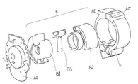
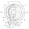
1 is a view showing a perspective view and a developed view of a part of the main parts of an improved engine which is an object of the present invention;
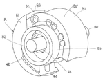
2 is a perspective view of a stator of the engine of Fig. 1; Fig.
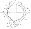
3 is a view showing a middle vertical section view of the stator of FIG. 2 along the plane of section III-III of FIG. 5; FIG.
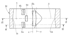
4 is a view of a view in a vertical section similar to that of FIG. 3 but more sideways along the plane of section IV-IV of FIG. 5; FIG.
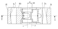
5 is a sectional view of the stator of Figs. 2, 3 and 4 along the plane of the section VV of Figs. 3 and 4; Fig.
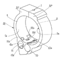
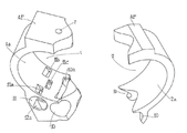
6 shows a perspective view of a set of rotor parts of the engine of FIG. 1, including a compression section, an expansion section and mutual hinge elements thereof, such elements being represented in a random arrangement for a drive shaft;
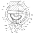
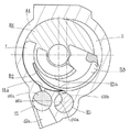
FIG. 7 shows a middle vertical section view of the rotor portions of FIG. 6 housed in the stator of FIG. 3 and occurs concurrently with the step for drawing in outside air, while the valve is subjected to final compression ≪ / RTI >
8 shows a detail and magnified view of the same engine of FIG. 7, showing the step of igniting the combustion mixture following the stage of maximum compression of the combustion air and preceding the useful expansion step;
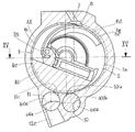
9 shows an engine diagram similar to that of FIG. 7, showing an initial useful expansion step immediately following the ignition phase of FIG. 8, with the exhaust duct closed and the external air intake duct initially closed; drawing;
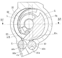
- Fig. 10 shows a further embodiment of the same engine of Fig. 9, with the same inflation element, in the subsequent intermediate inflating stage, closing the duct for discharging the exhaust gases by the expansion rotary element and simultaneously closing the air intake duct FIG.
11 shows a view of the same engine of FIG. 10 along the plane of section IV-IV of the stator of FIG. 5 and in accordance with the corresponding plane XI-XI of FIG. 16, Is already started and the step for drawing in the outside air is finished, the final stage of the maximum expansion is shown;
12 is a view of the engine at the moment immediately following the diagram of Fig. 11, but is shown according to the cutting plane III-III of Fig. 5 and the planes of XII-XII of Fig. 16, Air is also drawn from the side air inlets of the stator covers so that it is released from the different holes for this valve but also from the compression compartment to the ignition compartment and into the expansion compartment, ≪ Desc /
13 shows a view of the same engine of FIG. 11 at the moment immediately following the view of FIG. 12, in which the discharge valve is closed and the side air intake of the outside air continues, while the main intake valve is kept closed ≪ / RTI > showing the end of the washing step;
14 shows a view according to the plane of the section IV-IV of the stator of Fig. 5, as in Fig. 13, already started by the compression rotary element, while still opening the appropriate valve and closing the discharge compartment ≪ / RTI > showing the step of compressing the combustion air in which the intake phase is started;
15 is a view in cross section of the engine of Fig. 10 along the plane of section XV-XV of Fig. 10 and showing an intermediate stage of the useful expansion; Fig.
16 shows a view in cross section of the engine of FIG. 11, according to the plane of section XVI-XVI of FIG. 11, and showing the steps for discharging the burned gases; FIG.
17 shows a view in cross section of the engine of FIG. 9 along the plane of the section plane XVII-XVII of FIG. 9, showing the maximum compression of the combustion air and its mixing into the fuel in the stator ignition chamber , An initial useful phase of the expansion rotor element;
- Fig. 18 shows a cross-sectional view of the stator of Figs. 2 to 3 and Fig. 4 for the discharge of the combustion gases and the washing mixture, separately from the fresh air intake for entering the thermal cycle of the engine of Fig. A representation of a perspective view of a pair of valves inserted into the compartments;
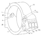
19 is a perspective view of the same stator of FIG. 2, shown in bottom view, to highlight separate separate outlets of combusted gases and cleaning mixture, apart from aspirating outside air;
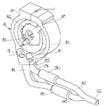
Figure 20 is a perspective view of the engine of this patent when the engine to be patented is associated with the two exhaust ducts of Figures 18 and 19 interposed between the same engine and exhaust end ducts;
21 is a perspective view and a developed view of the same rotor of Fig. 2, embodied in two different engageable portions; Fig.
In the drawings, the same specification is intended to be represented by the same reference numeral or the same reference numeral.
1, in accordance with the present invention, an improved rotary endothermic engine of the type with double center of rotation is constituted by one stator or housing A, which, as a result, The rotor B separately comprises a stator central body A1, a side cover A2 and a similar and uncovered cover A3 and the rotor B consequently has an expansion rotary element B1 ), A compression rotary element (B2) and a hinge linear element (B3) interposed between the expansion (B1) and compression (B2) elements, the same elements being more pronounced, Have been substantially devised in accordance with the teachings of the patent application numbers WO 2004/020791, WO 2010/031585 and BL2010A03.
In order to simplify the representation, the
For the sake of simplicity of the structure, the stator A1 has been represented by one single body, which includes the expansion (1) and compres- sion (2) compartments, with the other elements being listed separately. In fact, according to a preferred solution, the stator A1 can be embodied in two bodies A1 'to A1 ", as initially illustrated only in Figures 1 and 2 and in Figures 19 and 20 at the end. In the same figures, according to the above solution, the junction between the stator bodies A1 'to A1 "is preferably a
6, thereafter, according to the content of the substantially mentioned patent EP 1.154.139, one of the
Referring to Figures 2, 3, 4 and 5, the central body A1 of the stator A is provided with a recessed
The
A
At the approximate lower intersection between the
Referring to Figs. 3, 4 and 19, the
5 and 6, the foundation of the present invention is that the outer surface B1 'of the expansion rotary element B1 forms a curved surface and the outer surface B2' of the compression rotor element B2 forms a curved surface The
5, the
6, the expansion rotary element B1 is provided with an outer convex surface B1 '(protruding from the surface), whereas the compression element B2 is provided with an outer concave surface B2' The convex surface B2 'and the concave surface B1' being identical between themselves and having an arch profile of the
Between the depths of the
The depth and shape of the
A greater advantage of the present invention is that a significant reduction in the value of the interaxis distance s is possible if the capacities are the same and as a result the rotor faces B1 ' It is clear that the length of the stroke that the hinge element B3 had to perform so far is to be reduced to ensure continuous sliding of the hinge element B3 to B2 '. By reducing the vibration and ensuring better engine stability, a substantial reduction of the current accelerations and decelerations in each single stroke due to the reduction of the stroke of the hinge element B3 is possible.
Ultimately, the present capacity of the engine of the type still mentioned above and the substantial overall dimensions of the present invention is capable of significantly reducing the vibrations caused by abrupt changes in the length and speed of the hinge element B3, , The present invention is capable of increasing the number of revolutions of the stator (B) while reducing the problems of balance, according to one of the stated objectives.
The limitations of the same inter-axis distance s are therefore such that according to another of the stated objectives the appropriate bearings of the
8 and 9, the presence of the convex surface B1 'of the expansion element B1 below the
2 to 6 and 18, the
The
2 to 6 and 18, the
The
2 to 5 and 18, by accommodating the
2 to 5 and 18 and 19, the insertion and rotation of the
As already noted, the
In order to carry out the above-mentioned function of regulating the discharge of combustion gases and cleaning mixtures, the
Since the main parts of the engine have been described, the operation of the engine is then summarized with the help of the figures of the drawings in vertical cuts from 7 to 14 and in figures from 15 to 17.
As described above, FIG. 7 depicts the engine stage with curved walls being inspected and illustrates the final stage of compressing the combustion air in the
By the maximum compression of the combustion mixture applied by the counterclockwise rotation of the compression element B2, the explosion phase of this mixture is reached, as represented in Figures 8 to 9 and 17, Is determined by the ignition of a spark plug or an injector arranged in its
In the combustion mixture ignition in the
10 and 15, a useful step of inflating the combustion gases in the
11 and 16, the
Referring to Figure 12, with a rotation following inertia, the expansion rotor B1 begins to compress air in the
19 and 20, the
Referring to Fig. 13, with the activation of the
Referring to Figure 14, in relation to the situation 13, the same compartment 2 (1) which is much more compressed by rotation in the rotor B1 in the
By way of example only, it is possible to have the convex surface B1 'of the expansion rotor element B1 and to have the convex surface B1' of the compression rotor element B2, like the
Ultimately, according to the stated main purposes, the internal
It is possible to minimize the difference in translational speed of the hinge rotor element B3 joining the rotor elements B1 and B2 by minimizing the distances or the inter-axis distance s, , Even a considerable increase in the number of revolutions of the engine is possible, resulting in a reduction of mutual accelerations and decelerations.
The curved surface B1 'existing on the side of the expansion rotor B1 is, according to the purpose of the other of the stated purposes, at the instant of maximum power, which appears immediately after the steps for igniting the mixture, It is possible to increase the surface with respect to the prior art.
Due to the reduction of the distance s between the axes xy of the
The specific shape of the
Of course, and as has already been indicated, the solution is intended only as an example and is not intended to be limiting. For example, with respect to a curved surface shape having a shape such as "V" or a rectangular shape, for example,
For example, in the case of a stator A1 comprising two or more series of rotating elements B properly synchronized to supply a
Referring to Figure 21, there is shown a further variant of the embodiment of the stator A1 in the two bodies A1 'to A1 ", which can be arranged side by side with respect to the solutions illustrated in Figures 1, 2, 19 and 20, And the joining sides are not only orthogonal to the cross profile between the
However, these and other similar modifications or changes are intended to fall within the purview of the invention to be protected.
In the following paragraphs, preferred embodiments of the present invention are described:
1. An endothermic rotary engine having a double center of rotation optimized by curved walls and differentiated discharges to thermodynamically and mechanically optimize the system, the system comprising two exhaust outlets of two different gases In addition to being able to have the same, the side surfaces of the rotating elements and the corresponding inner surfaces of the inner body have an inter-axis spacing between the compression and expansion elements of the rotor, for an engine of equivalent size having flat non- By having a specific shape comprising cavities and convexities that create an ideal relationship between the expansion and compression of the volumes which are capable of reducing the length of the stator or of the passages of the stator to corresponding axle spacings of the housing passages, Of the different and sequential exhaust and cleaning steps of the engine to complete the efficiency Points are taken.
2. An endothermic rotary engine having a double center of rotation which is completed by folded walls and differentiated discharges in accordance with
3. An endothermic rotary engine having a double center of rotation according to one or more of
4. An endothermic rotary engine having a double center of rotation according to one or more of
5. An endothermic rotary engine having a double center of rotation completed by folded walls and differentiated discharges according to one or more of
6. An endothermic rotary engine having a double center of rotation according to one or more of
7. An endothermic rotary engine having a double center of rotation according to one or more of
8. An endothermic rotary engine having a double rotation center according to one or more of
9. An endothermic rotary engine having a double center of rotation according to one or more of
10. An endothermic rotary engine having a double rotation center according to one or more of
11. An endothermic rotary engine having a double rotation center according to one or more of
12. An endothermic rotary engine having a double center of rotation according to one or more of
13. An endothermic rotary engine having a double center of rotation completed by folded walls and differentiated discharges according to one or more of
14. An endothermic rotary engine having a double center of rotation according to one or more of
15. An endothermic rotary engine having a double center of rotation according to one or more of
16. An endothermic rotary engine having a double center of rotation according to one or more of
17. An endothermic rotary engine having a double center of rotation according to one or more of
18. An endothermic rotary engine having a double center of rotation according to one or more of
19. An endothermic rotary engine having a double center of rotation according to one or more of
Claims (15)
The spark ignition engine includes:
(1) having a compartment (1, 2), a first side cover (A2) and a second side cover (A3), the compartment comprising an expansion compartment (1), a compression compartment Comprising a combustion chamber in the upper part of the compartment (1, 2), the stator (A),
And a hinge linear element (B3) interposed between the expansion rotary element (B1) and the compression rotary element (B2) and between the expansion rotary element (B1) and the compression rotary element (B2) (B) arranged in the housing (1, 2)
Characterized in that the expansion compartment (1) comprises an internal concave surface (1a) and the compression compartment (2) comprises an internal convex surface (2a).
Characterized in that the expansion rotary element (B1) comprises an outer convex surface (B1 ') corresponding to the internal concave surface (1a) of the compartment (1, 2) and the compression rotary element (B2) And an outer concave surface (B2 ') corresponding to said inner convex surface (2a) of said spark ignition engine (2).
Wherein the concave surface and the convex surface are embodied in an arch-shaped profile.
Wherein the concave surface and the convex surface have the same profile and depth values.
The stator central body A1 comprises a cylindrical intake sheet 10 communicating with the compartments 1 and 2 for introducing air into the compartments 1 and 2 and a compartment 1, And a cylindrical discharge seat (11) in communication with the spark ignition engine.
Wherein the cylindrical intake sheet and the cylindrical discharge sheet are arranged between the inner concave surface and the inner convex surface (1a, 2a).
Wherein the cylindrical discharge seat (10) comprises a slot (10a) extending across the width of the stator central body (A1) to communicate with the compartment (1,2).
The cylindrical discharge seat (11) comprises a plurality of upper side ducts (11a, 11b, 11c) for communicating with the expansion compartment (1).
The upper side ducts are formed as two upper side ducts 11a and 11b and a central duct 11c and the central duct 11c is displaced from the two upper side ducts along the inner side of the compartment Spark ignition engine.
Wherein the discharge seat (11) comprises a plurality of lower side ducts (12a, 12b, 12c).
The lower side ducts (12a, 12b, 12c) are aligned with the upper side ducts (11a, 11b, 11c).
The spark ignition engine includes:
(1) having a compartment (1, 2), a first side cover (A2) and a second side cover (A3), the compartment comprising an expansion compartment (1), a compression compartment Comprising a combustion chamber in the upper part of the compartment (1, 2), the stator (A),
And a hinge linear element (B3) interposed between the expansion rotary element (B1) and the compression rotary element (B2) and between the expansion rotary element (B1) and the compression rotary element (B2) (B) arranged in the housing (1, 2)
The stator central body A1 comprises a cylindrical intake sheet 10 communicating with the compartments 1 and 2 to introduce air into the compartments 1 and 2 and a compartment 1, And a cylindrical discharge seat (11) in communication with the spark ignition engine.
Wherein said cylindrical discharge seat (10) comprises a slot (10a) extending across the width of said stator central body (A1) for communicating with said compartment (1,2).
The cylindrical discharge seat 11 includes a plurality of upper side ducts 11a, 11b and 11c for communicating with the expansion compartment 1 and the upper side ducts are preferably connected to two upper side ducts 11a, 11b and a central duct (11c), said central duct (11c) being displaced along said inner side of said compartment from said two upper side ducts.
The outlet sheet 11 includes a plurality of lower side ducts 12a, 12b and 12c and the lower side ducts 12a, 12b and 12c are preferably formed in the upper side ducts 11a, 11c. ≪ / RTI >
Applications Claiming Priority (3)
| Application Number | Priority Date | Filing Date | Title |
|---|---|---|---|
| ITBL2012A000010 | 2012-11-30 | ||
| IT000010A ITBL20120010A1 (en) | 2012-11-30 | 2012-11-30 | ROTARY ENDOTHERMAL ENGINE WITH DOUBLE ROTATION CENTER, PERFECTED WITH WALL-RETAINING WALLS AND DIFFERENTIAL EXHAUSTS |
| PCT/EP2013/075273 WO2014083204A2 (en) | 2012-11-30 | 2013-12-02 | Ignition engine of the rotary type with a double rotation center |
Publications (1)
| Publication Number | Publication Date |
|---|---|
| KR20150091151A true KR20150091151A (en) | 2015-08-07 |
Family
ID=48047047
Family Applications (1)
| Application Number | Title | Priority Date | Filing Date |
|---|---|---|---|
| KR1020157017487A KR20150091151A (en) | 2012-11-30 | 2013-12-02 | Ignition engine of the rotary type with a double rotation center |
Country Status (12)
| Country | Link |
|---|---|
| US (1) | US9874098B2 (en) |
| EP (1) | EP2925967B1 (en) |
| JP (1) | JP2016502018A (en) |
| KR (1) | KR20150091151A (en) |
| CN (1) | CN105026688A (en) |
| BR (1) | BR112015012279A2 (en) |
| CA (1) | CA2892232A1 (en) |
| HK (1) | HK1215965A1 (en) |
| IT (1) | ITBL20120010A1 (en) |
| MX (1) | MX2015006846A (en) |
| RU (1) | RU2666036C2 (en) |
| WO (1) | WO2014083204A2 (en) |
Families Citing this family (3)
| Publication number | Priority date | Publication date | Assignee | Title |
|---|---|---|---|---|
| GB201804184D0 (en) * | 2018-03-15 | 2018-05-02 | Libralato Ltd Pension Plan | A simplifield multi-axial rotary technology engine |
| IT202100006404A1 (en) | 2021-03-17 | 2022-09-17 | Litm Libralato Innovation Thermal Machines S R L | IMPROVED STEAM ENGINE, WITH DOUBLE CENTER OF ROTATION PISTON |
| IT202100007868A1 (en) | 2021-03-30 | 2022-09-30 | Litm Libralato Innovation Thermal Machines S R L | IMPROVED STEAM ENGINE WITH DOUBLE CENTER OF ROTATION PISTON |
Family Cites Families (18)
| Publication number | Priority date | Publication date | Assignee | Title |
|---|---|---|---|---|
| DE830440C (en) * | 1950-01-12 | 1952-02-04 | Ferdinand Spitznas Maschinenfa | In particular, reversible rotary piston engine driven by compressed air |
| US3324839A (en) * | 1965-10-08 | 1967-06-13 | John R Erwin | Rolling piston engine |
| DE2338962A1 (en) * | 1973-08-01 | 1975-02-13 | Walter Kral | Manual or power driven rotary piston pump - has tooth shaped piston and an eccentrically mounted rotary piston valve |
| GB2083557A (en) * | 1980-08-08 | 1982-03-24 | Osmond Leonard David | Rotary Positive-displacement Fluid-machines |
| JPS60132030A (en) | 1983-10-11 | 1985-07-13 | シオドア ゴ−ドン ラ−ソン | Rotary engine |
| US4548171A (en) | 1983-10-11 | 1985-10-22 | Larson Theodore G | Rotary engine |
| ATE50822T1 (en) | 1985-10-02 | 1990-03-15 | Michael L Zettner | ROTARY MOTOR. |
| CN1051072A (en) * | 1990-12-06 | 1991-05-01 | 申卫民 | Rotary engine |
| IT1250184B (en) * | 1991-06-04 | 1995-04-03 | Rotary endothermic engine with two centres of rotation | |
| CH685450A5 (en) * | 1992-04-01 | 1995-07-14 | Lindau Tech Forsch & Entw Gmbh | Internal-axis rotary piston engine. |
| RU2068106C1 (en) * | 1994-03-09 | 1996-10-20 | Юрий Михайлович Колотилин | Method of operation of rotary internal combustion engine and rotary internal combustion engine |
| DE4424626C2 (en) * | 1994-07-13 | 2003-04-30 | Gerhard Gitzel | Rotary piston engine |
| RU2172850C2 (en) * | 1999-09-28 | 2001-08-27 | Ичетовкин Петр Ефимович | Multipurpose rotary internal combustion engine |
| GB0200991D0 (en) * | 2002-01-17 | 2002-03-06 | Ea Technical Services Ltd | Compressor with variable pressure and flow control |
| ITBL20020014A1 (en) * | 2002-08-28 | 2004-02-29 | Ruggero Libralato | ENDOTHERMAL ROTARY MOTOR WITH DOUBLE ROTATION CENTER |
| US7500463B2 (en) * | 2006-11-20 | 2009-03-10 | Shuba Yaroslav M | Shuba rotary internal combustion engine with rotating combustion chambers |
| WO2009036475A1 (en) * | 2007-09-21 | 2009-03-26 | Hochgatterer, Manuel | Rotary piston machine |
| ITBL20080014A1 (en) * | 2008-09-19 | 2010-03-19 | Libralato Ruggero | THERMO-DYNAMIC CYCLE OF COMBUSTION ENGINE, IN PARTICULAR OF THE ROTARY TYPE WITH DOUBLE ROTATION CENTER AND MOTOR SO AS IT IS MADE |
-
2012
- 2012-11-30 IT IT000010A patent/ITBL20120010A1/en unknown
-
2013
- 2013-12-02 WO PCT/EP2013/075273 patent/WO2014083204A2/en active Application Filing
- 2013-12-02 CA CA2892232A patent/CA2892232A1/en not_active Abandoned
- 2013-12-02 EP EP13811398.0A patent/EP2925967B1/en not_active Not-in-force
- 2013-12-02 JP JP2015544497A patent/JP2016502018A/en active Pending
- 2013-12-02 BR BR112015012279A patent/BR112015012279A2/en not_active IP Right Cessation
- 2013-12-02 RU RU2015123147A patent/RU2666036C2/en not_active IP Right Cessation
- 2013-12-02 US US14/648,415 patent/US9874098B2/en not_active Expired - Fee Related
- 2013-12-02 KR KR1020157017487A patent/KR20150091151A/en not_active Application Discontinuation
- 2013-12-02 MX MX2015006846A patent/MX2015006846A/en unknown
- 2013-12-02 CN CN201380071280.9A patent/CN105026688A/en active Pending
-
2016
- 2016-03-24 HK HK16103478.7A patent/HK1215965A1/en unknown
Also Published As
| Publication number | Publication date |
|---|---|
| EP2925967B1 (en) | 2017-10-18 |
| CN105026688A (en) | 2015-11-04 |
| ITBL20120010A1 (en) | 2014-05-31 |
| CA2892232A1 (en) | 2014-06-05 |
| RU2666036C2 (en) | 2018-09-05 |
| RU2015123147A (en) | 2017-01-10 |
| BR112015012279A2 (en) | 2018-06-26 |
| WO2014083204A2 (en) | 2014-06-05 |
| US20150300173A1 (en) | 2015-10-22 |
| EP2925967A2 (en) | 2015-10-07 |
| WO2014083204A3 (en) | 2014-07-24 |
| US9874098B2 (en) | 2018-01-23 |
| HK1215965A1 (en) | 2016-09-30 |
| MX2015006846A (en) | 2016-03-21 |
| JP2016502018A (en) | 2016-01-21 |
Similar Documents
| Publication | Publication Date | Title |
|---|---|---|
| JP4418784B2 (en) | Rotary engine | |
| JP2008045513A (en) | Vane type internal combustion engine | |
| KR20150091151A (en) | Ignition engine of the rotary type with a double rotation center | |
| JP5284790B2 (en) | Rotary combustion device | |
| JP2007512476A (en) | Dual rotor internal combustion engine | |
| JP2010513792A (en) | Rotary engine with cylinders of different shapes and volumes | |
| US6604503B2 (en) | Rotary machine | |
| US3692005A (en) | Internal pressure engine | |
| US20110186006A1 (en) | Method for providing a thermo-dynamic cycle of a combustion engine, in particular of a rotary type with a double center of rotation | |
| JP2001505273A (en) | Bladed rotary engine with regenerative preheating | |
| US5429083A (en) | Rotary internal combustion twin engine | |
| WO2006016358A2 (en) | Rotary internal combustion engine with coupled cylinders | |
| EP1117902A1 (en) | Rotary machine | |
| CN101852123A (en) | Cycloid rotor engine | |
| KR20020090286A (en) | Rotary engine | |
| WO2018184035A1 (en) | Two-stroke cycle rotary internal combustion engine | |
| JPH0742868B2 (en) | Rotary internal combustion engine | |
| RU2693550C1 (en) | Internal combustion rotor engine with asymmetric compression and expansion | |
| RU2220308C2 (en) | Rotary engine | |
| KR101372013B1 (en) | Internal combustion engine | |
| CN113864044A (en) | Birotor variable force arm engine | |
| RU9263U1 (en) | CONTINUOUS COMBUSTION ROTARY ENGINE | |
| GB2358675A (en) | A rotary engine pump or motor | |
| JP2005256609A (en) | Rotary engine | |
| JP2001241301A (en) | Rotary engine |
Legal Events
| Date | Code | Title | Description |
|---|---|---|---|
| WITN | Withdrawal due to no request for examination |