KR20150075524A - Cooking appliance and burner unit - Google Patents
Cooking appliance and burner unit Download PDFInfo
- Publication number
- KR20150075524A KR20150075524A KR1020130163567A KR20130163567A KR20150075524A KR 20150075524 A KR20150075524 A KR 20150075524A KR 1020130163567 A KR1020130163567 A KR 1020130163567A KR 20130163567 A KR20130163567 A KR 20130163567A KR 20150075524 A KR20150075524 A KR 20150075524A
- Authority
- KR
- South Korea
- Prior art keywords
- burner
- gas
- frame
- catalyst body
- catalyst
- Prior art date
Links
Images


Classifications
-
- F—MECHANICAL ENGINEERING; LIGHTING; HEATING; WEAPONS; BLASTING
- F24—HEATING; RANGES; VENTILATING
- F24C—DOMESTIC STOVES OR RANGES ; DETAILS OF DOMESTIC STOVES OR RANGES, OF GENERAL APPLICATION
- F24C3/00—Stoves or ranges for gaseous fuels
- F24C3/08—Arrangement or mounting of burners
-
- F—MECHANICAL ENGINEERING; LIGHTING; HEATING; WEAPONS; BLASTING
- F23—COMBUSTION APPARATUS; COMBUSTION PROCESSES
- F23J—REMOVAL OR TREATMENT OF COMBUSTION PRODUCTS OR COMBUSTION RESIDUES; FLUES
- F23J15/00—Arrangements of devices for treating smoke or fumes
- F23J15/02—Arrangements of devices for treating smoke or fumes of purifiers, e.g. for removing noxious material
-
- F—MECHANICAL ENGINEERING; LIGHTING; HEATING; WEAPONS; BLASTING
- F24—HEATING; RANGES; VENTILATING
- F24C—DOMESTIC STOVES OR RANGES ; DETAILS OF DOMESTIC STOVES OR RANGES, OF GENERAL APPLICATION
- F24C15/00—Details
- F24C15/001—Details arrangements for discharging combustion gases
-
- F—MECHANICAL ENGINEERING; LIGHTING; HEATING; WEAPONS; BLASTING
- F24—HEATING; RANGES; VENTILATING
- F24C—DOMESTIC STOVES OR RANGES ; DETAILS OF DOMESTIC STOVES OR RANGES, OF GENERAL APPLICATION
- F24C15/00—Details
- F24C15/32—Arrangements of ducts for hot gases, e.g. in or around baking ovens
-
- F—MECHANICAL ENGINEERING; LIGHTING; HEATING; WEAPONS; BLASTING
- F24—HEATING; RANGES; VENTILATING
- F24C—DOMESTIC STOVES OR RANGES ; DETAILS OF DOMESTIC STOVES OR RANGES, OF GENERAL APPLICATION
- F24C3/00—Stoves or ranges for gaseous fuels
- F24C3/008—Ranges
-
- F—MECHANICAL ENGINEERING; LIGHTING; HEATING; WEAPONS; BLASTING
- F24—HEATING; RANGES; VENTILATING
- F24C—DOMESTIC STOVES OR RANGES ; DETAILS OF DOMESTIC STOVES OR RANGES, OF GENERAL APPLICATION
- F24C3/00—Stoves or ranges for gaseous fuels
- F24C3/04—Stoves or ranges for gaseous fuels with heat produced wholly or partly by a radiant body, e.g. by a perforated plate
- F24C3/047—Ranges
-
- F—MECHANICAL ENGINEERING; LIGHTING; HEATING; WEAPONS; BLASTING
- F24—HEATING; RANGES; VENTILATING
- F24C—DOMESTIC STOVES OR RANGES ; DETAILS OF DOMESTIC STOVES OR RANGES, OF GENERAL APPLICATION
- F24C3/00—Stoves or ranges for gaseous fuels
- F24C3/04—Stoves or ranges for gaseous fuels with heat produced wholly or partly by a radiant body, e.g. by a perforated plate
- F24C3/06—Stoves or ranges for gaseous fuels with heat produced wholly or partly by a radiant body, e.g. by a perforated plate without any visible flame
- F24C3/067—Ranges
-
- F—MECHANICAL ENGINEERING; LIGHTING; HEATING; WEAPONS; BLASTING
- F24—HEATING; RANGES; VENTILATING
- F24C—DOMESTIC STOVES OR RANGES ; DETAILS OF DOMESTIC STOVES OR RANGES, OF GENERAL APPLICATION
- F24C3/00—Stoves or ranges for gaseous fuels
- F24C3/08—Arrangement or mounting of burners
- F24C3/085—Arrangement or mounting of burners on ranges
- F24C3/087—Arrangement or mounting of burners on ranges in baking ovens
-
- F—MECHANICAL ENGINEERING; LIGHTING; HEATING; WEAPONS; BLASTING
- F24—HEATING; RANGES; VENTILATING
- F24C—DOMESTIC STOVES OR RANGES ; DETAILS OF DOMESTIC STOVES OR RANGES, OF GENERAL APPLICATION
- F24C3/00—Stoves or ranges for gaseous fuels
- F24C3/12—Arrangement or mounting of control or safety devices
- F24C3/126—Arrangement or mounting of control or safety devices on ranges
Abstract
Description
본 발명은 조리기기 및 버너 유닛에 관한 것이다. The present invention relates to a cooking apparatus and a burner unit.
조리기기는 음식물을 가열하여 조리하는 기기이다. 조리기기 중에서 쿡탑은 가스연소에 의해서 발생하는 열에 의해 음식물을 가열한다. A cooking device is a device that heats and cooks food. Among the cookware, the cooktop heats the food by the heat generated by the gas burning.
선행문헌인 한국등록특허공보 제0829624호(등록일 2008.05.07.)에는 가열조리기기가 개시된다. Korean Patent Registration No. 0829624 (registered on May 28, 2008), which is a prior art document, discloses a heating cooker.
상기 가열조리기기는, 케이스와, 상기 케이스의 상측에 놓이는 탑 플레이트와, 상기 케이스 내부에 구비되는 버너시스템을 포함한다. The heating cooker includes a case, a top plate placed on the upper side of the case, and a burner system provided inside the case.
상기 버너시스템은, 버너포트와, 혼합관유닛, 연소 부재 및 노즐 유닛을 포함한다. 그리고, 혼합가스가 연소 부재에서 연소된다. The burner system includes a burner port, a mixing pipe unit, a combustion member, and a nozzle unit. Then, the mixed gas is burned in the combustion member.
그런데, 종래의 가열조리기기에 의하면, 혼합가스가 상기 연소 부재에서 완전하게 연소되지 않으며, 혼합가스의 불완전 연소에 의해서 일산화탄소가 발생하게 되는 문제가 있다. However, according to the conventional heating cooking apparatus, there is a problem that the mixed gas is not completely burned in the combustion member, and carbon monoxide is generated by incomplete combustion of the mixed gas.
본 발명의 목적은, 혼합가스의 불완전 연소에 따른 일산화탄소의 배출이 최소화되는 조리기기 및 버너 유닛을 제공하는 것에 있다. It is an object of the present invention to provide a cooking apparatus and a burner unit in which emission of carbon monoxide due to incomplete combustion of a mixed gas is minimized.
일 측면에 따른 조리기기는, 케이스; 상기 케이스에 안착되는 탑 플레이트; 및 상기 케이스에 수용되는 버너 유닛을 포함하고, 상기 버너 유닛은, 가스와 공기를 공급받는 버너 포트; 상기 버너 포트 내의 가스와 공기의 혼합 가스를 연소시키기 위한 연소 부재; 상기 버너 포트에 안착되며, 상기 연소 부재에 의해서 연소된 가스 및 상기 혼합 가스의 불완전 연소에 의해서 발생되는 일산화탄소가 유동하는 배기 유로를 형성하는 버너 프레임; 및 상기 배기 유로 상에 배치되며, 상기 일산화탄소가 산소와 반응하도록 하기 위한 촉매를 가지는 촉매 바디를 포함한다. A cooking device according to one aspect includes: a case; A top plate seated in the case; And a burner unit accommodated in the case, wherein the burner unit comprises: a burner port for receiving gas and air; A combustion member for burning a gas mixture of gas and air in the burner port; A burner frame mounted on the burner port and forming an exhaust passage through which carbon monoxide generated by incomplete combustion of the gas and the mixed gas combusted by the combustion member flows; And a catalyst body disposed on the exhaust passage and having a catalyst for allowing the carbon monoxide to react with oxygen.
본 실시 예에서, 상기 촉매 바디는 담체에 촉매가 코팅되어 형성된다. In this embodiment, the catalyst body is formed by coating a catalyst on a carrier.
본 실시 예에서, 상기 촉매 바디에는 상기 일산화탄소가 통과하기 위한 다수의 홀이 형성된다. In this embodiment, the catalyst body is provided with a plurality of holes through which the carbon monoxide passes.
본 실시 예에서, 상기 촉매 바디에는 수평 방향 및 상하 방향으로 각각 다수의 홀이 형성된다. In this embodiment, a plurality of holes are formed in the catalyst body in the horizontal direction and in the vertical direction, respectively.
본 실시 예에서, 상기 다수의 홀은, 제1크기를 가지는 다수의 제1홀과, 상기 다수의 제1홀 보다 하방에 위치되며, 상기 제1크기 보다 큰 제2크기를 가지는 다수의 제2홀을 포함한다. In this embodiment, the plurality of holes may include a plurality of first holes having a first size, and a plurality of second holes having a second size larger than the first size, Holes.
본 실시 예에서, 상기 촉매 바디를 상기 버너 프레임에 고정시키기 위한 고정부를 더 포함한다. In this embodiment, it further comprises a fixing portion for fixing the catalyst body to the burner frame.
본 실시 예에서, 상기 고정부는, 상기 촉매 바디의 상측에 안착되는 상부 바디와, 상기 상부 바디에서 연장되며, 상기 버너 프레임 내에서 가스의 유동 방향과 나란한 방향으로 이격되는 제1연장부와 제2연장부와, 상기 각 연장부에서 수평 방향으로 절곡되며 상기 버너 프레임에 안착되는 하부 바디를 포함하고, 상기 촉매 바디는 상기 제1연장부와 상기 제2연장부 사이에 삽입된다. In this embodiment, the fixing portion includes an upper body that is seated on the upper side of the catalyst body, a first extending portion extending from the upper body and spaced apart from the burner frame in a direction parallel to the flow direction of the gas, And a lower body which is horizontally bent at each of the extensions and is seated in the burner frame, the catalyst body being inserted between the first and second extensions.
본 실시 예에서, 상기 하부 바디에는 상기 버너 프레임에 체결되기 위한 체결부재가 관통하는 체결홀이 형성된다. In the present embodiment, the lower body is formed with a fastening hole through which fastening members for fastening to the burner frame pass.
본 실시 예에서, 상기 고정부는, 상기 제1연장부 및 상기 제2연장부 각각에서 절곡되어 형성되며 상기 버너 프레임의 측면에 접촉되는 접촉부를 더 포함한다. In the present embodiment, the fixing portion may further include a contact portion which is formed by bending at each of the first and second extensions and contacts the side surface of the burner frame.
본 실시 예에서, 상기 고정부는, 상기 촉매 바디의 상측에 안착되는 상부 바디와, 상기 상부 바디에서 연장되며, 상기 버너 프레임 내에서 가스의 유동 방향과 나란한 방향으로 이격되는 제1연장부와 제2연장부와, 상기 각 연장부에서 절곡되어 형성되며, 상기 버너 프레임의 측면에 접촉되는 접촉부를 포함하고, 상기 접촉부에는 상기 버너 프레임에 체결되기 위한 체결부재가 관통하는 체결홀이 형성된다. In this embodiment, the fixing portion includes an upper body that is seated on the upper side of the catalyst body, a first extending portion extending from the upper body and spaced apart from the burner frame in a direction parallel to the flow direction of the gas, And a contact portion which is bent at each of the extended portions and is in contact with a side surface of the burner frame. The contact portion is formed with a fastening hole through which the fastening member for fastening to the burner frame passes.
본 실시 예에서, 상기 고정부는, 상기 버너 프레임에 구비되며, 가스의 유동 방향과 나란한 방향으로 이격되는 복수의 리브를 포함하고, 상기 촉매 바디는, 상기 복수의 리브 사이에 삽입된다. In this embodiment, the fixing portion is provided in the burner frame and includes a plurality of ribs spaced in a direction parallel to the flow direction of the gas, and the catalyst body is inserted between the plurality of ribs.
본 실시 예에서, 상기 고정부는, 상기 버너 프레임에 함몰 형성되어 상기 촉매 바디를 수용하는 수용홈을 포함한다. In this embodiment, the fixing portion includes a receiving groove formed in the burner frame to receive the catalyst body.
본 실시 예에서, 상기 촉매 바디는 상기 탑 플레이트의 저면과 접촉한다. In this embodiment, the catalyst body is in contact with the bottom surface of the top plate.
본 실시 예에서, 상기 버너 프레임의 측면에는 홀이 형성되고, 상기 촉매 바디는 상기 홀을 관통하여 상기 버너 프레임 내부로 삽입되는 조리기기. In this embodiment, a hole is formed in a side surface of the burner frame, and the catalyst body is inserted into the burner frame through the hole.
본 실시 예에서, 상기 버너 프레임에는, 산소를 포함한 공기가 유입되기 위한 유입홀이 형성되며, 상기 유입홀은 상기 버너 프레임에서의 가스의 유동 방향을 기준으로 상기 촉매 바디의 전방에 위치된다. In the present embodiment, the burner frame is provided with an inlet hole through which oxygen-containing air flows, and the inlet hole is located in front of the catalyst body with respect to the flow direction of the gas in the burner frame.
다른 측면에 따른 버너 유닛은, 가스와 공기를 공급받는 버너 포트; 상기 버너 포트 내의 가스와 공기의 혼합 가스를 연소시키기 위한 연소 부재; 상기 버너 포트에 안착되며, 상기 연소 부재에 의해서 연소된 가스 및 상기 혼합 가스의 불완전 연소에 의해서 발생되는 일산화탄소가 유동하는 배기 유로를 형성하는 버너 프레임; 및 상기 배기 유로 상에 배치되며, 상기 일산화탄소가 산소와 반응하도록 하기 위한 촉매를 가지는 촉매 바디를 포함하고, 상기 촉매 바디는, 상기 일산화탄소가 통과하기 위한 다수의 홀을 포함한다.
A burner unit according to another aspect includes: a burner port for receiving gas and air; A combustion member for burning a gas mixture of gas and air in the burner port; A burner frame mounted on the burner port and forming an exhaust passage through which carbon monoxide generated by incomplete combustion of the gas and the mixed gas combusted by the combustion member flows; And a catalyst body disposed on the exhaust passage, the catalyst body having a catalyst for allowing the carbon monoxide to react with oxygen, and the catalyst body includes a plurality of holes through which the carbon monoxide passes.
제안되는 발명에 의하면, 버너 프레임에 촉매 장치가 구비됨에 따라 혼합가스의 불완전 연소에 의해서 발생된 일산화탄소가 촉매에 의해서 산호와 반응하여 이산화탄소로 변화되므로, 조리기기의 외부로 배출되는 일산화탄소의 양이 최소화될 수 있는 장점이 있다. According to the present invention, since the catalyst device is provided in the burner frame, the carbon monoxide generated by the incomplete combustion of the mixed gas reacts with the coral by the catalyst to be changed into carbon dioxide, so that the amount of carbon monoxide discharged to the outside of the cooking device is minimized There is an advantage that can be.
또한, 상기 촉매 장치가 설치되는 상기 버너 프레임의 제2프레임의 높이가 제1프레임의 높이보다 높으므로, 상기 제1프레임에서의 가스의 유동속도 보다 상기 제2프레임에서의 가스의 유동속도가 줄어든다. 따라서, 상기 제2프레임에서 일산화탄소의 유동 속도가 줄어들게 되므로, 상기 촉매 바디를 통과하는 속도가 줄어들어 촉매와 일산화탄소의 접촉시간이 증가되어 상기 조리기기의 외부로 배출되는 일산화탄소의 양이 최소화될 수 있다. Since the height of the second frame of the burner frame on which the catalytic device is installed is higher than the height of the first frame, the flow velocity of the gas in the second frame is lower than the flow velocity of the gas in the first frame . Accordingly, since the flow rate of carbon monoxide in the second frame is reduced, the speed of passing through the catalyst body is reduced, so that the contact time between the catalyst and carbon monoxide is increased, so that the amount of carbon monoxide discharged to the outside of the cooking apparatus can be minimized.
또한, 버너 프레임으로 일산화탄소와 반응하기 위한 산소가 공급되므로, 기 조리기기의 외부로 배출되는 일산화탄소의 양이 최소화될 수 있다. In addition, since oxygen for reacting with carbon monoxide is supplied to the burner frame, the amount of carbon monoxide discharged to the outside of the cooking apparatus can be minimized.
또한, 연소가스를 냉각하기 위한 공기가 상기 버너 프레임으로 공급되므로, 조리기기의 외부로 배출되는 연소가스의 온도가 낮아지는 장점이 있다. Further, since the air for cooling the combustion gas is supplied to the burner frame, there is an advantage that the temperature of the combustion gas discharged to the outside of the cooking apparatus is lowered.
도 1은 제1실시 예에 따른 조리기기의 사시도.
도 2는 도 1의 조리기기에서 탑 플레이트가 제거된 상태를 보여주는 도면.
도 3은 제1실시 예에 따른 버너 유닛의 분해사시도.
도 4는 제1실시 예에 따른 버너 프레임의 측면도.
도 5는 제1실시 예에 따른 촉매 장치의 사시도.
도 6은 도 4의 촉매 장치의 분해 사시도.
도 7은 도 1의 조리기기의 수직 단면도.
도 8은 제2실시 예에 따른 고정부의 사시도.
도 9는 제3실시 예에 따른 버너 프레임의 단면도.
도 10은 제4실시 예에 따른 버너 프레임의 단면도.
도 11은 제5실시 예에 따른 촉매 바디의 사시도. 1 is a perspective view of a cooking apparatus according to a first embodiment;
Fig. 2 is a view showing a state in which the top plate is removed from the cooking apparatus of Fig. 1; Fig.
3 is an exploded perspective view of the burner unit according to the first embodiment;
4 is a side view of the burner frame according to the first embodiment;
5 is a perspective view of the catalyst device according to the first embodiment;
6 is an exploded perspective view of the catalyst device of FIG.
7 is a vertical sectional view of the cooking appliance of Fig.
8 is a perspective view of a fixing unit according to the second embodiment;
9 is a sectional view of the burner frame according to the third embodiment.
10 is a sectional view of a burner frame according to a fourth embodiment;
11 is a perspective view of the catalyst body according to the fifth embodiment.
이하, 본 발명의 일부 실시 예들을 예시적인 도면을 통해 상세하게 설명한다. 각 도면의 구성요소들에 참조부호를 부가함에 있어서, 동일한 구성요소들에 대해서는 비록 다른 도면상에 표시되더라도 가능한 한 동일한 부호를 가지도록 하고 있음에 유의해야 한다. 또한, 본 발명의 실시 예를 설명함에 있어, 관련된 공지 구성 또는 기능에 대한 구체적인 설명이 본 발명의 실시예에 대한 이해를 방해한다고 판단되는 경우에는 그 상세한 설명은 생략한다. Hereinafter, some embodiments of the present invention will be described in detail with reference to exemplary drawings. It should be noted that, in adding reference numerals to the constituent elements of the drawings, the same constituent elements are denoted by the same reference symbols as possible even if they are shown in different drawings. In the following description of the embodiments of the present invention, a detailed description of known functions and configurations incorporated herein will be omitted when it may make the difference that the embodiments of the present invention are not conclusive.
또한, 본 발명의 실시예의 구성 요소를 설명하는 데 있어서, 제 1, 제 2, A, B, (a), (b) 등의 용어를 사용할 수 있다. 이러한 용어는 그 구성 요소를 다른 구성 요소와 구별하기 위한 것일 뿐, 그 용어에 의해 해당 구성 요소의 본질이나 차례 또는 순서 등이 한정되지 않는다. 어떤 구성 요소가 다른 구성요소에 "연결", "결합" 또는 "접속"된다고 기재된 경우, 그 구성 요소는 그 다른 구성요소에 직접적으로 연결되거나 접속될 수 있지만, 각 구성 요소 사이에 또 다른 구성 요소가 "연결", "결합" 또는 "접속"될 수도 있다고 이해되어야 할 것이다. In describing the components of the embodiment of the present invention, terms such as first, second, A, B, (a), and (b) may be used. These terms are intended to distinguish the constituent elements from other constituent elements, and the terms do not limit the nature, order or order of the constituent elements. When a component is described as being "connected", "coupled", or "connected" to another component, the component may be directly connected or connected to the other component, Quot; may be "connected," "coupled," or "connected. &Quot;
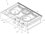
도 1은 제1실시 예에 따른 조리기기의 사시도이고, 도 2는 도 1의 조리기기에서 탑 플레이트가 제거된 상태를 보여주는 도면이다. FIG. 1 is a perspective view of a cooking apparatus according to a first embodiment, and FIG. 2 is a view showing a state where a top plate is removed from the cooking apparatus of FIG.
도 1 및 도 2를 참조하면, 본 발명의 일 실시 예에 따른 조리기기(1)는, 케이스(case: 10)와, 상기 케이스(10)의 상측에 안착되는 탑 플레이트(top plate: 11)를 포함할 수 있다. 1 and 2, a
또한, 상기 조리기기(1)는, 상기 케이스(10) 내에 수용되며 공기와 가스가 혼합된 혼합가스를 연소시키는 하나 이상의 버너 유닛(burner unit: 20)과, 상기 버너 유닛(20) 내에서 연소된 가스가 배출되기 위한 배출부(12)를 더 포함할 수 있다. 상기 배출부(12)는 상기 케이스(10)의 상측 후단부에 안착될 수 있다. The
도 2에는 일 예로 세 개의 버너 유닛(20)이 상기 케이스(10) 내에 배치되는 것이 도시되나, 본 발명에서 상기 버너 유닛(20)의 개수에는 제한이 없음을 밝혀둔다. 상기 배출부(12)는 연소가스가 배출되기 위한 다수의 배출홀(122)을 포함할 수 있다. In FIG. 2, for example, three
또한, 상기 조리기기(1)는, 상기 버너 유닛(20)으로 공급되는 가스가 유동하는 가스 공급관(14, 16)과, 상기 버너 유닛(20)으로 공급되는 가스의 양을 조절하기 위한 가스 밸브(gas valve: 15)와, 상기 버너 유닛(20)으로 가스를 분사하기 위한 노즐 유닛(nozzle unit: 30)과, 상기 가스 밸브(15)를 조작하기 위한 조작노브(13)를 더 포함할 수 있다. 상기 조작 노브(13)는 상기 케이스(10)의 전면에 설치될 수 있다. 그리고, 상기 가스밸브(15), 노즐 유닛(30), 및 조작 노브(13) 각각은 버너유닛(20)의 개수와 동일한 개수로 구비될 수 있다. The
상기 가스 공급관(14, 16)은 상기 가스 밸브(15)의 일측에 연결되는 공통 공급관(14)과, 상기 가스 밸브(15)의 타측에 연결되며 상기 각 버너 유닛(20)으로 가스를 공급하는 개별 공급관(16)을 포함할 수 있다. The
이하에서는 상기 버너 유닛에 대해서 상세하게 설명하기로 한다. Hereinafter, the burner unit will be described in detail.
도 3은 제1실시 예에 따른 버너 유닛의 분해사시도이고, 도 4는 제1실시 예에 따른 버너 프레임의 측면도이고, 도 5는 제1실시 예에 따른 촉매 장치의 사시도이고, 도 6은 도 4의 촉매 장치의 분해 사시도이다. FIG. 3 is a perspective view of the burner unit according to the first embodiment, FIG. 4 is a side view of the burner frame according to the first embodiment, FIG. 5 is a perspective view of the catalyst apparatus according to the first embodiment, 4 is an exploded perspective view of the catalytic device.
도 3 내지 도 6을 참조하면, 본 발명의 일 실시 예에 따른 버너 유닛(20)은, 혼합가스가 유입되는 버너포트(burner pot: 210)와, 상기 버너포트(210)에 안착되며 혼합가스를 연소에 의해서 발생되는 열에 의해서 가열되는 연소 부재(12)와, 상기 버너포트(210)에 안착되며, 상기 연소 부재(12) 상에서 연소된 연소가스의 배기 유로를 제공하는 버너 프레임(burner frame: 220)과, 혼합가스의 불완전 연소에 의해서 발생된 일산화탄소를 이산화탄소로 변화시키기 위한 촉매를 가지는 촉매 장치(240)를 포함한다. 3 to 6, a
상기 버너포트(210)는 원통 형상으로 형성되는 제1포트(211)와, 상기 제1포트(211) 내부 공간에 배치되는 제2포트(212)를 포함한다. 상기 제2포트(212)의 내부 공간은 상기 제2포트(212)의 외면과 상기 제1포트(211) 내면 사이의 공간과 구획된다. 따라서, 상기 조작노브(13)의 조작에 따라 혼합가스가 상기 제1포트(211) 또는 제2포트(212)로 공급되거나 상기 제1포트(211) 및 제2포트(212) 각각으로 공급될 수 있다. The
상기 제1포트(211)에는 제1혼합관(217)이 연결되고, 상기 제2포트(211)에는 제2혼합관(218)이 연결된다. 상기 제2포트(212)는 일 예로 원통 형상으로 형성될 수 있으나 이에 제한되는 것은 아니다. A
상기 노즐 유닛(30)에서 가스가 상기 각 혼합관(217, 218)를 분사되는 과정에서 상기 혼합관(217, 218) 주변의 공기가 상기 혼합관(217, 218)으로 유입될 수 있다. 그리고, 상기 혼합관(217, 218)에서 가스와 공기가 일차적으로 혼합되고, 상기 각 포트(211, 212)의 내부 공간에서 가스와 공기가 이차적으로 혼합된다. Air in the vicinity of the mixing
상기 제2혼합관(218)은 상기 제1포트(211)를 관통하여 상기 제2포트(212)에 연결될 수 있다. The
다른 예로서, 상기 제1혼합관(217)과 상기 제2혼합관(218)이 상기 버너포트(210)와 일체로 형성되는 것도 가능하다. As another example, the
상기 버너 포트(210)의 상측, 실질적으로 상기 제1포트(211)에는 상기 연소 부재(230)가 안착되는 제1안착부(214)가 형성된다. 상기 연소 부재(230)가 상기 제1안착부(214)에 안착되면, 상기 연소 부재(230)는 상기 제1포트(211)의 내부 공간 및 상기 제2포트(212)의 내부 공간을 동시에 커버한다. 다른 예로서, 상기 연소 부재(230)가 상기 버너 프레임(220)에 안착되는 것도 가능하다. A
따라서, 상기 연소 부재(230)에서 상기 제1포트(211)의 혼합가스 및 상기 제2포트(212)의 혼합가스가 연소될 수 있다. Therefore, the mixed gas of the
다른 예로서, 상기 연소 부재(230)는 상기 제1포트(211)를 커버하며 링 형상으로 형성되는 제1연소 부재와, 상기 제2포트(212)를 커버하는 제2연소 부재를 포함할 수 있다. As another example, the
상기 버너 포트(210)의 상측, 실질적으로 상기 제1포트(211)에는 상기 버너 프레임(220)이 안착되기 위한 제2안착부(215)가 형성된다. A
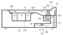
상기 버너 프레임(220)은 제1높이(H1)를 가지는 제1프레임(221)과, 제1높이(H1) 보다 높은 제2높이(H2)를 가지는 제2프레임(222)을 포함할 수 있다. 상기 제2프레임(222)은 가스의 유동을 기준으로 상기 제1프레임(221)의 후방에 위치된다. 즉, 연소가스 또는 일산화탄소는 상기 제1프레임을 유동한 후에 제2프레임(222)을 유동한다. The
상기 제1프레임(221)에는 혼합가스의 연소를 위한 점화부(228)가 설치된다. 상기 점화부(228)는 상기 연소 부재(230)의 상방에 위치된다. 상기 제2포트(212) 내의 혼합가스가 먼저 점화되도록, 상기 점화부(228)의 단부는 상기 제2포트(212)와 상하 방향으로 오버랩되는 위치에 배치된다. The
따라서, 상기 연소 부재(230)를 통과한 혼합가스는 상기 점화부(228)에 의해서 점화되어 연소되고, 상기 연소 부재(230)를 가열하며, 그 이후에는 상기 연소 부재(230) 상에서 혼합가스가 연소된다. Accordingly, the mixed gas passing through the
그리고, 상기 연소 부재(230)는 중앙 부분(제2포트와 대응되는 부분)이 먼저 가열되고, 중앙 부분 외의 나머지 부분(제1포트와 대응되는 부분임)이 가열된다. 그리고, 상기 연소 부재(230)의 중앙 부분 이외의 부분의 열에 의해서 상기 제1포트(211)의 혼합가스가 연소된다. Then, the central portion (corresponding to the second port) of the
상기 제1프레임(221)은 제1바닥면(221A)을 포함하고, 상기 제2프레임(222)은 제1바닥면(222B)을 포함한다. 상기 제2바닥면(222A)은 상기 제1바닥면(221A) 보다 낮게 위치된다. 그리고, 상기 제1바닥면(221A)과 상기 제2바닥면(222A)은 경사면(222C)에 의해서 연결될 수 있다. The
따라서, 상기 경사면(222C)에 의해서 상기 제1프레임(221)의 가스가 상기 제2프레임(222B)으로 유동될 때의 유동 저항이 최소화될 수 있다. Therefore, the flow resistance when the gas of the
상기 제1프레임(221)에는 상기 연소 부재(230)가 관통하기 위한 홀(223)이 형성된다. 즉, 상기 연소 부재(230)가 상기 버너포트(210)의 제1안착부(214)에 안착된 상태에서 상기 버너 프레임(220)이 상기 제2안착부(215)에 안착되면, 상기 연소 부재는 상기 홀(223)을 관통하게 된다. A
다른 예로서, 상기 연소 부재(230)가 상기 홀(223)을 관통하지 않고, 상기 제1프레임(221)의 하면에 접촉하는 것도 가능하다. 이 경우에는 상기 연소 부재에 의해서 연소된 가스가 상기 홀(223)을 통과하게 된다. As another example, it is possible for the
그리고, 상기 버너 프레임(220)은 상기 탑 플레이트(11)의 하면과의 접촉 면적을 늘리기 위한 접촉부(227)를 포함한다. 상기 접촉부(227)는 상기 버너 프레임(220)의 상측 단부에서 수평 방향으로 연장된다. 상기 접촉부(227)가 상기 탑 플레이트(11)의 하면과 접촉함에 따라서 상기 탑 플레이트(11)와 상기 버너 프레임(220) 사이로 연소가스가 유동하는 것이 방지될 수 있다. The
상기 촉매 장치(240)는, 상기 버너 프레임(220)의 제2프레임(222)에 설치될 수 있다. The
상기 촉매 장치(240)는, 연소가스 및 일산화탄소가 통과할 수 있는 다수의 홀(252)을 가지는 촉매 바디(250)와, 상기 촉매 바디(250)를 상기 버너 프레임(220)에 고정시키기 위한 고정부(242)를 포함할 수 있다. The
이 때, 상기 연소 부재(230)의 열에 의해서 상기 촉매 바디(250)가 손상되는 것이 방지되도록, 상기 촉매 장치(240)는 상기 배출부(12)와 인접한 위치에서 상기 버너 프레임(220)에 설치될 수 있다. 따라서, 상기 촉매 바디(250)와 상기 배출부(12)의 거리는 상기 촉매 바디(250)와 상기 연소 부재(230)의 거리 보다 짧다. The
상기 다수의 홀(252)은, 원형이나 다각형 또는 허니콤 형상으로 형성될 수 있으나, 이에 제한되는 것은 아니다. The plurality of
상기 촉매 바디(250)에는 좌우 방향으로 다수의 홀(252)이 배치되고, 상하 방향으로도 다수의 홀(252)이 배치된다. 따라서, 상기 촉매 바디(250)가 다수의 홀(252)을 포함하므로, 일산화탄소와 접촉하는 면적이 증가될 수 있게 된다. The
또한, 일산화탄소의 접촉면적이 증가되도록, 상기 촉매 바디(250)의 좌우 폭은 상기 제2프레임(222)의 좌우 폭과 동일하게 형성될 수 있다. 또한, 상기 촉매 장치(240)의 높이는 상기 제2프레임(222)의 높이와 동일하게 형성될 수 있다. 따라서, 상기 촉매 장치(240)는 상기 제2프레임(222)에 설치된 상태에서 상기 탑 플레이트(11)의 하면에 접촉할 수 있다. In addition, the lateral width of the
상기 촉매 바디(250)는 세라믹 재질의 담체에 촉매가 코팅됨으로써 형성된다. 이 때, 상기 담체는 촉매가 담긴 용기에 침지시킴으로써 촉매를 코팅하거나 촉매를 담체에 분사함으로써 상기 담체에 촉매를 코팅시킬 수 있다. The
혼합가스의 불완전연소에 의해서 발생된 일산화탄소는 아래의 반응식과 같이 촉매에 의해서 산소와 반응하여 이산화탄소로 변화된다. The carbon monoxide generated by the incomplete combustion of the mixed gas reacts with oxygen by the catalyst and changes into carbon dioxide as shown in the following reaction formula.
2C0 + O2 → 2CO22C0 + O2 - > 2CO2
상기 버너 프레임(220)에 상기 촉매 장치(240)가 설치되면, 상기 촉매 장치(240)가 유동 저항으로 작용할 수 있다. 상기 촉매 장치(240)가 유동 저항으로 작용하면 상기 버너 유닛(20)으로 유입되는 공기의 양이 줄어들어 연소 성능이 저하될 수 있다. When the
그러나, 본 발명에 의하면 상술한 바와 같이 상기 촉매 장치(240)가 설치되는 제2프레임(222)의 높이가 제1프레임(221)의 높이보다 높게 형성됨에 따라, 상기 제2프레임(222)의 가스 유로 단면적이 상기 제1프레임(221)의 가스 유로 단면적 보다 증가되므로 상기 촉매 장치(250)에 의한 유동 저항이 최소화될 수 있어 공기가 상기 버너 유닛(20)으로 안정적으로 유입될 수 있다. However, according to the present invention, since the height of the
일산화탄소가 상기 촉매 바디(250)와 접촉하는 시간이 증가될 수록 상기 조리기기에서 배출되는 일산화탄소의 양이 줄어들 수 있다. The amount of carbon monoxide emitted from the cooking apparatus can be reduced as the time for which carbon monoxide is in contact with the
본 발명의 경우, 상기 촉매 장치(240)가 설치되는 상기 제2프레임(222)의 높이가 제1프레임(221)의 높이보다 높으므로, 상기 제1프레임(221)에서의 가스의 유동속도 보다 상기 제2프레임(222)에서의 가스의 유동속도가 줄어든다. Since the height of the
따라서, 상기 제2프레임(222)에서 일산화탄소의 유동 속도가 줄어들게 되므로, 상기 촉매 바디(250)의 홀(252)을 통과하는 속도가 줄어들어 촉매와 일산화탄소의 접촉시간이 증가된다. 따라서, 상기 조리기기(1)의 외부로 배출되는 일산화탄소의 양이 최소화될 수 있다. Accordingly, since the flow rate of carbon monoxide in the
일산화탄소가 촉매에 의해서 산소와 반응하기 위해서는 상기 버너 프레임(220) 내의 산소가 충분히 확보되어야 한다. In order for carbon monoxide to react with oxygen by the catalyst, oxygen in the
따라서, 본 발명에서는 상기 버너 프레임(220) 내로 산소가 공급되기 위하여 상기 제2프레임(222)의 제2바닥면(222B)에는 산소를 포함한 공기가 유입되는 하나 이상의 제1유입홀(224)이 형성될 수 있다. 또는 상기 제2프레임(222)의 측면에 제1유입홀(224)이 형성되는 것도 가능하다. Accordingly, in the present invention, at least one
이 때, 일산화탄소와 함께 산소가 상기 촉매 바디(250)를 통과하여야 하므로, 상기 제1유입홀(224)은 가스의 유동을 기준으로 상기 촉매 장치(240)의 전방에 위치된다. At this time, the
따라서, 일산화탄소는 상기 제1유입홀(224)을 통하여 유입된 산소와 함께 상기 촉매 바디(250)의 홀(252)을 통과하게 되고, 이 과정에서 촉매에 의해서 일산화탄소와 산소가 반응하여 이산화탄소로 변화된다. Therefore, carbon monoxide passes through the
이 때, 다수의 제1유입홀(224)이 상기 제2프레임(222)의 제2바닥면(222B)에 형성되며, 가스의 유동 방향과 수평 방향으로 교차되도록 배열된다. 따라서, 상기 제2프레임(222) 내에 산소가 전체적으로 골고루 유입될 수 있다. At this time, a plurality of first inlet holes 224 are formed in the second
상기 고정부(242)는, 상기 촉매 바디(250)의 상면에 안착되는 상부 바디(243)와, 상기 상부 바디(243)의 양측 단부에서 하방으로 연장되는 제1연장부(244) 및 제2연장부(245)를 포함한다. 상기 제1연장부(244) 및 상기 제2연장부(245)는 상기 상부 바디(243)에서 수직하게 절곡된다. 상기 제1연장부(244)와 제2연장부(245)는 상기 버너 프레임에서 가스의 유동 방향과 나란한 방향으로 이격되어 배치된다. 상기 상부 바디(243)는 상기 탑 플레이트(11)의 하면과 접촉한다.The fixing
상기 고정부(242)는, 상기 각 연장부(244, 245)에서 수평 방향으로 연장되는 제1하부 바디(246) 및 제2하부 바디(247)를 더 포함한다. 다른 예로서, 제1연장부와 제2연장부 중 어느 하나에서 하부 바디가 연장되는 것도 가능하다. The fixing
상기 각 하부 바디(246, 247)는 상기 제2프레임(220)의 제2바닥면(222B)에 안착된다. Each of the
그리고, 상기 각 하부 바디(246, 247)에는 도시되지 않은 체결부재가 체결되기 위한 체결홀(248)이 형성된다. 물론, 상기 제2프레임(222)의 제2바닥면(222B)에도 상기 체결부재가 체결되기 위한 체결홀(226)이 형성된다. The
상기 촉매 바디(250)는 상기 제1연장부(244)와 제2연장부(245) 사이로 삽입될 수 있다. The
따라서, 상기 하부 바디(246, 247)가 상기 체결부재에 의해서 상기 제2프레임(222)에 체결되면, 상기 상부 바디(242)에 의해서 상기 촉매 바디(250)의 상하 방향 이동이 방지될 수 있다. 그리고, 상기 제1연장부(244)와 상기 제2연장부(245)에 의해서 상기 촉매 바디(250)의 전후 방향 이동이 방지될 수 있다. Therefore, when the
본 명세서에서 전후 방향은 상기 버너 프레임(220)에서의 가스의 유동방향과 나란한 방향을 의미하고, 좌우 방향은 상기 가스의 유동방향과 수평 방향으로 교차되는 방향을 의미한다. In this specification, the forward and backward direction means a direction parallel to the flow direction of the gas in the
상기 고정부(242)는 상기 각 연장부(244, 245)에서 수직하게 절곡되며 상기 제2프레임(222)의 측면에 접촉하는 접촉부(249)를 더 포함할 수 있다. 다른 예로서, 상기 제1연장부와 상기 제2연장부 중 하나 이상에서 상기 접촉부가 연장되는 것도 가능하다. The fixing
상기 접촉부(249)가 상기 각 연장부(244, 245)에서 절곡됨에 따라 상기 고정부(242)의 강도가 향상될 수 있고, 상기 제2프레임(222)에 접촉함에 따라서 일산화탄소가 상기 제2프레임(222)과 상기 고정부(242) 사이를 유동하는 것이 방지될 수 있다.The strength of the fixing
도 7은 도 1의 조리기기의 수직 단면도이다. 7 is a vertical sectional view of the cooking apparatus of Fig.
도 7을 참조하면, 상기 케이스(10) 내부에는 공기의 유동을 위한 팬(50)이 구비된다. 상기 케이스(10)의 바닥면에는 외부공기가 유입되기 위한 공기 유입홀(102)이 형성된다. Referring to FIG. 7, a
상기 케이스(10) 내부에는 상기 공기 유입홀(102)을 통하여 유입된 공기를 상기 버너 프레임(220)으로 안내하기 위한 안내 가이드(104, 105)가 구비된다. Guide guides 104 and 105 for guiding the air introduced through the air inlet holes 102 to the
상기 안내 가이드(104)는, 제1유로(P1)를 형성하기 위한 제1안내 가이드(104)와, 상기 제1안내 가이드(104)와 연통되며 제2유로(P2)를 형성하기 위한 제2안내 가이드(105)를 포함한다. The
상기 제2프레임(222)의 제2바닥면(222B)에는 상기 제1유로(P1)로 상의 공기가 유입되기 위한 제2유입홀(225)이 형성된다. The second
따라서, 상기 제1유로(P1)의 공기는 상기 제2유입홀(225)을 통하여 상기 버너 프레임(220) 내로 유입되고, 상기 제2유로(P2)의 공기는 상기 제1유입홀(222)을 통하여 상기 버너 프레임(220)로 유입된다. The air of the first flow path P1 flows into the
이 때, 상기 제2유입홀을 상기 버너 프레임(220) 내의 가스 유동 방향을 기준으로 상기 촉매 장치(240)의 후방에 위치된다. 따라서, 상기 촉매 장치(240)는 상기 제1유입홀(224)과 상기 제2유입홀(225) 사이에서 상기 제2프레임(222)에 설치된다. At this time, the second inflow hole is positioned behind the
상기 버너 프레임(220)을 유동하는 가스는 고온이므로, 고온의 가스가 상기 배출부(12)를 통하여 조리기기의 외부로 배출되면 사용자가 위험할 수 있다. Since the gas flowing through the
그러나, 본 발명의 경우, 상기 촉매 장치(240)를 통과한 가스가 상기 제2유입홀(225)을 통하여 유입된 공기와 혼합되어 냉각된 후에 상기 배출부(12)를 통하여 조리기기의 외부로 배출되므로, 사용자의 위험이 줄어들게 된다. However, in the case of the present invention, the gas passing through the
또한, 상기 제2유입홀(225)을 통하여 유입된 공기에 의해서 상기 촉매 장치(240)도 냉각될 수 있다. Also, the
이하에서는 본 발명의 조리기기의 작용에 대해서 설명하기로 한다. Hereinafter, the operation of the cooking apparatus of the present invention will be described.
상기 조작노브(30)를 조작하여 상기 가스밸브(15)가 작동하면, 상기 버너포트(210)로 혼합가스가 공급된다. 그리고, 상기 팬(50)이 회전된다. 상기 버너포트(210)로 공급된 혼합가스는 상기 점화부(228)에 의해서 점화되어 연소된다. 그리고, 상기 혼합가스의 연소에 의해서 발생된 열에 의해서 상기 연소 부재(230)가 가열된다. When the
상기 연소 부재(230)의 방사 에너지는 적어도 가시광선 대역의 주파수가 포함되어 있다. 따라서, 가시광선에 의해서 본 발명의 조리기기가 동작 중임을 사용자가 인식할 수 있다. 그리고, 상기 연소 부재(230)에 의해서 음식물이 가열될 수 있고, 상기 음식물은 상기 탑 플레이트(11)의 전도열에 의해서도 가열될 수 있다. The radiation energy of the
상기 연소 부재(230)에 의해서 연소된 가스와 일산화탄소는 상기 버너 프레임(220)의 제1프레임(221)에서 상기 제2프레임(222)으로 유동하게 된다. 상기 제2프레임(222)으로 유동한 일산화탄소는 상기 제1유입홀(224)을 통하여 유입된 산소와 함께 상기 촉매 바디(250)의 홀(252)을 통과하면서 촉매에 의해서 이산화탄소로 변화된다. The gas and carbon monoxide burnt by the
그리고, 이산화탄소 및 연소가스는 상기 제2유입홀(225)을 통하여 유입된 공기에 의해서 냉각된 후에 상기 배출부(12)의 배출홀(122)을 통하여 상기 조리기기(1)의 외부로 배출된다.
The carbon dioxide and the combustion gas are cooled by the air introduced through the
도 8은 제2실시 예에 따른 고정부의 사시도이다. 8 is a perspective view of the fixing unit according to the second embodiment.
도 8을 참조하면, 본 실시 예에 따른 고정부(340)는, 상기 촉매 바디(250)의 상면에 안착되는 상부 바디(343)와, 상기 상부 바디(343)의 양측 단부에서 하방으로 연장되는 제1연장부(344) 및 제2연장부(345)를 포함한다. 상기 제1연장부(344) 및 상기 제2연장부(345)는 상기 상부 바디(343)에서 수직하게 절곡된다. 8, the fixing
상기 고정부(340)는 상기 각 연장부(344, 345)에서 수직하게 절곡되며 상기 제2프레임(222)의 측면에 접촉하는 접촉부(346)를 더 포함할 수 있다. The fixing
그리고, 상기 접촉부(346)에는 체결부재가 체결되기 위한 체결홀(347)이 형성될 수 있다. 즉, 상기 접촉부(346)는 상기 제2프레임(222)의 측면에 체결될 수 있다. 이 경우에는 상기 제2프레임(222)의 측면에 상기 체결부재가 체결되기 위한 체결홀(미도시)이 형성될 수 있다.
The
도 9는 제3실시 예에 따른 버너 프레임의 단면도이다. 9 is a sectional view of the burner frame according to the third embodiment.
도 9를 참조하면, 본 실시 예의 버너 프레임(420)은 제1프레임(421)과 제2프레임(422)을 포함한다. 상기 제1프레임(421)과 상기 제2프레임(422)의 기본 구조 및 높이 차이는 제1실시 예에서 설명한 것과 동일하므로 자세한 설명은 생략하기로 한다. Referring to FIG. 9, the
상기 제2프레임(422)에는 촉매 바디(250)의 위치를 고정하기 위한 고정부가 구비된다. 상기 고정부는, 복수의 리브(423, 424)를 포함할 수 있다. 상기 복수의 리브(423, 424)는 상기 버너 프레임(420)에서의 가스의 유동 방향과 나란한 방향으로 이격된다. The second frame 422 is provided with a fixing part for fixing the position of the
상기 복수의 리브(423, 424)는 상기 촉매 바디(250)의 전면에 접촉하는 제1리브(423)와 상기 촉매 바디(250)의 후면에 접촉하는 제2리브(424)를 포함한다. 상기 제1리브(423)와 상기 제2리브(424) 간의 간격은 상기 촉매 바디(250)의 전후 폭과 동일할 수 있다. 따라서, 상기 촉매 바디(250)는 상기 제1리브(423)와 상기 제2리브(424) 사이에 끼워지고, 상기 제2프레임(222)에 안착된다. The plurality of
상기 촉매 바디(250)는 상기 탑 플레이트(11)의 저면에 접촉할 수 있다. 따라서, 상기 촉매 바디(250)의 상하 방향 이동이 방지될 수 있다. The
즉, 본 실시 예에 의하면, 간단한 구조에 의해서 촉매 바디가 상기 버너 프레임에 고정될 수 있다.
That is, according to this embodiment, the catalyst body can be fixed to the burner frame by a simple structure.
도 10은 제4실시 예에 따른 버너 프레임의 단면도이다. 10 is a sectional view of the burner frame according to the fourth embodiment.
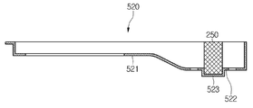
도 10을 참조하면, 본 실시 예에 따른 버너 프레임(520)은, 제1프레임(521)과 제2프레임(522)을 포함한다. 상기 제1프레임(521)과 상기 제2프레임(522)의 기본 구조 및 높이 차이는 제1실시 예에서 설명한 것과 동일하므로 자세한 설명은 생략하기로 한다. Referring to FIG. 10, the
상기 제2프레임(522)에는 상기 촉매 바디(250)를 제2프레임(522)에 고정시키기 위한 고정부가 구비된다. 상기 고정부는 상기 촉매 바디(250)를 수용하기 위한 수용홈(523)일 수 있다. 상기 수용홈(523)은 상기 제2프레임(522)의 바닥면이 하방으로 함몰됨에 따라 형성된다. The
상기 촉매 바디(250)는 상기 수용홈(523)에 수용된 상태에서 탑 플레이트(11)의 저면에 접촉할 수 있다. 따라서, 상기 촉매 바디(250)의 상하 방향 이동이 방지될 수 있다. The
따라서, 본 실시 예에 의하면, 간단한 구조에 의해서 촉매 바디가 상기 버너 프레임에 고정될 수 있다.
Therefore, according to the present embodiment, the catalyst body can be fixed to the burner frame by a simple structure.
도 11은 제5실시 예에 따른 촉매 바디의 사시도이다. 11 is a perspective view of the catalyst body according to the fifth embodiment.
도 11을 참조하면, 본 실시 예의 촉매 바디(250)는 제1크기로 형성되는 다수의 제1홀(253)과, 제1크기 보다 큰 제2크기로 형성되는 다수의 제2홀(254)을 포함할 수 있다. 상기 다수의 제2홀(254)은 상기 다수의 제1홀(253) 보다 낮은 위치에 배치된다. Referring to FIG. 11, the
상기 버너 프레임(220) 내에서 가스의 유동을 살펴보면, 유로 단면을 기준으로 상측 영역을 유동하는 공기의 유동 속도가 하측 영역을 유동하는 공기의 유동 속도 보다 빠를 수 있다. The flow rate of the air flowing in the upper region may be faster than the flow rate of air flowing in the lower region with respect to the cross section of the flow passage.
따라서, 본 실시 예의 경우, 유로 단면에서 상부 영역을 유동하는 일산화탄소와 촉매 바디(250)의 접촉 시간이 증가되도록, 상기 다수의 제1홀(253)의 크기(또는 직경)가 하부 영역을 유동하는 일산화탄소가 통과하는 다수의 제2홀(254)의 크기(또는 직경)보다 작게 형성된다. Accordingly, in the present embodiment, the size (or diameter) of the
본 실시 예에서 상기 촉매 바디(250)를 높이를 이등분하는 지점을 기준으로 상측 부분에 상기 다수의 제1홀(253)이 형성되고, 하측 부분에 상기 다수의 제2홀(254)이 형성될 수 있다. In the present embodiment, the plurality of
다른 예로서, 상기 제2프레임(222)의 측면에 홀이 형성되고, 상기 촉매 바디는 상기 홀을 관통하여 상기 제2프레임에 삽입되는 것도 가능하다.
As another example, a hole may be formed on the side surface of the
이상에서, 본 발명의 실시예를 구성하는 모든 구성 요소들이 하나로 결합하거나 결합하여 동작하는 것으로 설명되었다고 해서, 본 발명이 반드시 이러한 실시예에 한정되는 것은 아니다. 즉, 본 발명의 목적 범위 안에서라면, 그 모든 구성 요소들이 하나 이상으로 선택적으로 결합하여 동작할 수도 있다. 또한, 이상에서 기재된 "포함하다", "구성하다" 또는 "가지다" 등의 용어는, 특별히 반대되는 기재가 없는 한, 해당 구성 요소가 내재할 수 있음을 의미하는 것이므로, 다른 구성 요소를 제외하는 것이 아니라 다른 구성 요소를 더 포함할 수 있는 것으로 해석되어야 한다. 기술적이거나 과학적인 용어를 포함한 모든 용어들은, 다르게 정의되지 않는 한, 본 발명이 속하는 기술 분야에서 통상의 지식을 가진 자에 의해 일반적으로 이해되는 것과 동일한 의미가 있다. 사전에 정의된 용어와 같이 일반적으로 사용되는 용어들은 관련 기술의 문맥상의 의미와 일치하는 것으로 해석되어야 하며, 본 발명에서 명백하게 정의하지 않는 한, 이상적이거나 과도하게 형식적인 의미로 해석되지 않는다. While the present invention has been described in connection with what is presently considered to be the most practical and preferred embodiment, it is to be understood that the invention is not limited to the disclosed embodiments. That is, within the scope of the present invention, all of the components may be selectively coupled to one or more of them. Furthermore, the terms "comprises", "comprising", or "having" described above mean that a component can be implanted unless otherwise specifically stated, But should be construed as including other elements. All terms, including technical and scientific terms, have the same meaning as commonly understood by one of ordinary skill in the art to which this invention belongs, unless otherwise defined. Commonly used terms, such as predefined terms, should be interpreted to be consistent with the contextual meanings of the related art, and are not to be construed as ideal or overly formal, unless expressly defined to the contrary.
이상의 설명은 본 발명의 기술 사상을 예시적으로 설명한 것에 불과한 것으로서, 본 발명이 속하는 기술 분야에서 통상의 지식을 가진 자라면 본 발명의 본질적인 특성에서 벗어나지 않는 범위에서 다양한 수정 및 변형이 가능할 것이다. 따라서, 본 발명에 개시된 실시예들은 본 발명의 기술 사상을 한정하기 위한 것이 아니라 설명하기 위한 것이고, 이러한 실시예에 의하여 본 발명의 기술 사상의 범위가 한정되는 것은 아니다. 본 발명의 보호 범위는 아래의 청구범위에 의하여 해석되어야 하며, 그와 동등한 범위 내에 있는 모든 기술 사상은 본 발명의 권리범위에 포함되는 것으로 해석되어야 할 것이다. The foregoing description is merely illustrative of the technical idea of the present invention, and various changes and modifications may be made by those skilled in the art without departing from the essential characteristics of the present invention. Therefore, the embodiments disclosed in the present invention are intended to illustrate rather than limit the scope of the present invention, and the scope of the technical idea of the present invention is not limited by these embodiments. The scope of protection of the present invention should be construed according to the following claims, and all technical ideas within the scope of equivalents should be construed as falling within the scope of the present invention.
10: 케이스
11: 탑 플레이트
20: 버너 유닛
50: 팬
210: 버너포트
220: 버너 프레임
230: 연소 부재
240: 촉매 장치10: Case 11: Top plate
20: burner unit 50: fan
210: burner port 220: burner frame
230: combustion member 240: catalytic device
Claims (16)
상기 케이스에 안착되는 탑 플레이트; 및
상기 케이스에 수용되는 버너 유닛을 포함하고,
상기 버너 유닛은, 가스와 공기를 공급받는 버너 포트;
상기 버너 포트 내의 가스와 공기의 혼합 가스를 연소시키기 위한 연소 부재;
상기 버너 포트에 안착되며, 상기 연소 부재에 의해서 연소된 가스 및 상기 혼합 가스의 불완전 연소에 의해서 발생되는 일산화탄소가 유동하는 배기 유로를 형성하는 버너 프레임; 및
상기 배기 유로 상에 배치되며, 상기 일산화탄소가 산소와 반응하도록 하기 위한 촉매를 가지는 촉매 바디를 포함하는 조리기기. case;
A top plate seated in the case; And
And a burner unit accommodated in the case,
The burner unit includes a burner port for receiving gas and air;
A combustion member for burning a gas mixture of gas and air in the burner port;
A burner frame mounted on the burner port and forming an exhaust passage through which carbon monoxide generated by incomplete combustion of the gas and the mixed gas combusted by the combustion member flows; And
And a catalyst body disposed on the exhaust passage and having a catalyst for allowing the carbon monoxide to react with oxygen.
상기 촉매 바디는 담체에 촉매가 코팅되어 형성되는 조리기기. The method according to claim 1,
Wherein the catalyst body is formed by coating a catalyst on a carrier.
상기 촉매 바디에는 상기 일산화탄소가 통과하기 위한 다수의 홀이 형성되는 조리기기. The method according to claim 1,
Wherein the catalyst body has a plurality of holes for allowing the carbon monoxide to pass therethrough.
상기 촉매 바디에는 수평 방향 및 상하 방향으로 각각 다수의 홀이 형성되는 조리기기. The method of claim 3,
Wherein a plurality of holes are formed in the catalyst body in the horizontal direction and in the vertical direction, respectively.
상기 다수의 홀은, 제1크기를 가지는 다수의 제1홀과,
상기 다수의 제1홀 보다 하방에 위치되며, 상기 제1크기 보다 큰 제2크기를 가지는 다수의 제2홀을 포함하는 조리기기. The method of claim 3,
The plurality of holes may include a plurality of first holes having a first size,
And a plurality of second holes located below the plurality of first holes and having a second size larger than the first size.
상기 촉매 바디를 상기 버너 프레임에 고정시키기 위한 고정부를 더 포함하는 조리기기. The method according to claim 1,
And a fixing unit for fixing the catalyst body to the burner frame.
상기 고정부는, 상기 촉매 바디의 상측에 안착되는 상부 바디와,
상기 상부 바디에서 연장되며, 상기 버너 프레임 내에서 가스의 유동 방향과 나란한 방향으로 이격되는 제1연장부와 제2연장부와,
상기 제1연장부 및 제2연장부 중 하나 이상에서 수평 방향으로 절곡되며 상기 버너 프레임에 안착되는 하부 바디를 포함하고,
상기 촉매 바디는 상기 제1연장부와 상기 제2연장부 사이에 삽입되는 조리기기. The method according to claim 6,
The fixing unit includes an upper body that is seated on the upper side of the catalyst body,
A first extension and a second extension extending from the upper body and spaced apart in a direction parallel to the flow direction of the gas in the burner frame,
And a lower body folded in a horizontal direction in at least one of the first and second extensions and seated in the burner frame,
Wherein the catalyst body is inserted between the first extension part and the second extension part.
상기 하부 바디에는 상기 버너 프레임에 체결되기 위한 체결부재가 관통하는 체결홀이 형성되는 조리기기. 8. The method of claim 7,
Wherein the lower body is formed with a fastening hole through which fastening members for fastening to the burner frame pass.
상기 고정부는, 상기 제1연장부 및 상기 제2연장부 중 하나 이상에서 절곡되어 형성되며 상기 버너 프레임의 측면에 접촉되는 접촉부를 더 포함하는 조리기기. 8. The method of claim 7,
Wherein the fixing portion further comprises a contact portion formed by bending at least one of the first extension portion and the second extension portion and contacting the side surface of the burner frame.
상기 고정부는, 상기 촉매 바디의 상측에 안착되는 상부 바디와,
상기 상부 바디에서 연장되며, 상기 버너 프레임 내에서 가스의 유동 방향과 나란한 방향으로 이격되는 제1연장부와 제2연장부와,
상기 제1연장부 및 제2연장부 중 하나 이상에서 절곡되어 형성되며, 상기 버너 프레임의 측면에 접촉되는 접촉부를 포함하고,
상기 접촉부에는 상기 버너 프레임에 체결되기 위한 체결부재가 관통하는 체결홀이 형성되는 조리기기. The method according to claim 6,
The fixing unit includes an upper body that is seated on the upper side of the catalyst body,
A first extension and a second extension extending in the upper body and spaced apart in a direction parallel to the flow direction of the gas in the burner frame,
And a contact portion that is formed by bending at least one of the first extension portion and the second extension portion and contacts the side surface of the burner frame,
Wherein the contact portion is formed with a fastening hole through which a fastening member for fastening to the burner frame passes.
상기 고정부는, 상기 버너 프레임에 구비되며, 가스의 유동 방향과 나란한 방향으로 이격되는 복수의 리브를 포함하고,
상기 촉매 바디는, 상기 복수의 리브 사이에 삽입되는 조리기기. The method according to claim 6,
Wherein the fixing portion is provided in the burner frame and includes a plurality of ribs spaced in a direction parallel to the flow direction of the gas,
Wherein the catalyst body is inserted between the plurality of ribs.
상기 고정부는, 상기 버너 프레임에 함몰 형성되어 상기 촉매 바디를 수용하는 수용홈을 포함하는 조리기기. The method according to claim 6,
Wherein the fixing portion includes a receiving recess formed in the burner frame to receive the catalyst body.
상기 촉매 바디는 상기 탑 플레이트의 저면과 접촉하는 조리기기. 13. The method according to claim 11 or 12,
Wherein the catalyst body is in contact with the bottom surface of the top plate.
상기 버너 프레임의 측면에는 홀이 형성되고, 상기 촉매 바디는 상기 홀을 관통하여 상기 버너 프레임 내부로 삽입되는 조리기기. The method according to claim 1,
Wherein a hole is formed in a side surface of the burner frame and the catalyst body is inserted into the burner frame through the hole.
상기 버너 프레임에는, 산소를 포함한 공기가 유입되기 위한 유입홀이 형성되며, 상기 유입홀은 상기 버너 프레임에서의 가스의 유동을 기준으로 상기 촉매 바디의 전방에 위치되는 조리기기. The method according to claim 1,
Wherein the burner frame is provided with an inlet hole through which oxygen-containing air flows, and the inlet hole is located in front of the catalyst body based on the flow of gas in the burner frame.
상기 버너 포트 내의 가스와 공기의 혼합 가스를 연소시키기 위한 연소 부재;
상기 버너 포트에 안착되며, 상기 연소 부재에 의해서 연소된 가스 및 상기 혼합 가스의 불완전 연소에 의해서 발생되는 일산화탄소가 유동하는 배기 유로를 형성하는 버너 프레임; 및
상기 배기 유로 상에 배치되며, 상기 일산화탄소가 산소와 반응하도록 하기 위한 촉매를 가지는 촉매 바디를 포함하고,
상기 촉매 바디는, 상기 일산화탄소가 통과하기 위한 다수의 홀을 포함하는 버너 유닛. A burner port for supplying gas and air;
A combustion member for burning a gas mixture of gas and air in the burner port;
A burner frame mounted on the burner port and forming an exhaust passage through which carbon monoxide generated by incomplete combustion of the gas and the mixed gas combusted by the combustion member flows; And
And a catalyst body disposed on the exhaust passage and having a catalyst for allowing the carbon monoxide to react with oxygen,
Wherein the catalyst body comprises a plurality of holes through which the carbon monoxide passes.
Priority Applications (3)
| Application Number | Priority Date | Filing Date | Title |
|---|---|---|---|
| KR1020130163567A KR101573989B1 (en) | 2013-12-26 | 2013-12-26 | Cooking appliance and burner unit |
| CN201410713325.4A CN104748166B (en) | 2013-12-26 | 2014-11-28 | Cooker |
| US14/582,369 US10125996B2 (en) | 2013-12-26 | 2014-12-24 | Cooking appliance and burner device |
Applications Claiming Priority (1)
| Application Number | Priority Date | Filing Date | Title |
|---|---|---|---|
| KR1020130163567A KR101573989B1 (en) | 2013-12-26 | 2013-12-26 | Cooking appliance and burner unit |
Publications (2)
| Publication Number | Publication Date |
|---|---|
| KR20150075524A true KR20150075524A (en) | 2015-07-06 |
| KR101573989B1 KR101573989B1 (en) | 2015-12-02 |
Family
ID=53481261
Family Applications (1)
| Application Number | Title | Priority Date | Filing Date |
|---|---|---|---|
| KR1020130163567A KR101573989B1 (en) | 2013-12-26 | 2013-12-26 | Cooking appliance and burner unit |
Country Status (3)
| Country | Link |
|---|---|
| US (1) | US10125996B2 (en) |
| KR (1) | KR101573989B1 (en) |
| CN (1) | CN104748166B (en) |
Families Citing this family (3)
| Publication number | Priority date | Publication date | Assignee | Title |
|---|---|---|---|---|
| KR101851862B1 (en) * | 2016-08-26 | 2018-04-24 | 엘지전자 주식회사 | A cooker having vent |
| CN108800129A (en) * | 2018-07-13 | 2018-11-13 | 珠海格力电器股份有限公司 | A kind of burner and gas combustion apparatus |
| CN112263153B (en) * | 2020-09-10 | 2022-03-22 | 广东美的厨房电器制造有限公司 | Combustion device and cooking equipment |
Family Cites Families (43)
| Publication number | Priority date | Publication date | Assignee | Title |
|---|---|---|---|---|
| US3698378A (en) * | 1968-07-12 | 1972-10-17 | Inst Gas Technology | Smooth top gas range |
| US3633562A (en) * | 1970-03-30 | 1972-01-11 | Columbia Gas Service Corp | Slightly pressurized flat-top stove |
| US3819334A (en) * | 1970-10-27 | 1974-06-25 | Mitsui Mining & Smelting Co | Catalytic reaction apparatus for purifying waste gases containing carbon monoxide |
| US3799142A (en) * | 1972-04-26 | 1974-03-26 | F Jensen | Method and apparatus for sequestering open flame combustion gas |
| US4138220A (en) * | 1978-02-13 | 1979-02-06 | Colonial Metals, Inc. | Apparatus for catalytic oxidation of grease and fats in low temperature fumes |
| EP0124022B1 (en) * | 1983-04-30 | 1989-06-07 | Schott Glaswerke | Cooker hob with gas heated hot plates and a continuous cooking area of glass-ceramic or similar material |
| JPS61202015A (en) * | 1985-03-01 | 1986-09-06 | Toyotomi Kogyo Co Ltd | Flame extinguishing device for kerosene stove |
| CA1303477C (en) * | 1988-06-06 | 1992-06-16 | Yoichiro Ohkubo | Catalytic combustion device |
| DE3844081A1 (en) * | 1988-12-28 | 1990-07-05 | Cramer Gmbh & Co Kg | COOKER WITH AT LEAST ONE COOKER |
| ES2018440A6 (en) * | 1989-12-11 | 1991-04-01 | Catalana Gas Sa | Improvements in gas cooker tops. |
| FR2678360B1 (en) * | 1991-06-28 | 1993-09-10 | Applic Gaz Sa | HEATING APPARATUS WITH CATALYTIC BURNER. |
| JP3036611B2 (en) * | 1992-06-15 | 2000-04-24 | 松下電器産業株式会社 | Catalytic combustion device |
| JPH0650555A (en) * | 1992-07-31 | 1994-02-22 | Matsushita Electric Ind Co Ltd | Exhaust device for grill |
| DE19545842C1 (en) * | 1995-12-08 | 1996-10-10 | Schott Glaswerke | Modular ceramic cooking hob |
| US6216687B1 (en) * | 1996-03-22 | 2001-04-17 | The Majestic Products Company | Unvented heating appliance having system for reducing undesirable combustion products |
| DE19637666A1 (en) * | 1996-09-16 | 1998-03-26 | Schott Glaswerke | Gas-pressure regulator for cooker with burners under glass or ceramic surface |
| KR20000016529A (en) | 1998-12-10 | 2000-03-25 | 젝미넥 알 에이. | Support structure for a catalyst |
| JP2001221406A (en) * | 2000-02-04 | 2001-08-17 | Hitachi Ltd | Boiler and its reconstruction method |
| CN2431514Y (en) * | 2000-04-29 | 2001-05-23 | 中国环境科学研究院 | Secondary combustion kitchen range without fume exhausting |
| ITMI20010247U1 (en) * | 2001-05-03 | 2002-11-04 | Whirlpool Co | RADIANT GAS ATMOSPHERIC BURNER |
| JP3822066B2 (en) * | 2001-06-20 | 2006-09-13 | リンナイ株式会社 | Gas cooker |
| US7878189B2 (en) * | 2002-11-29 | 2011-02-01 | Lg Electronics Inc. | Combustion fan installation structure of gas radiation oven range |
| CN100374779C (en) * | 2002-11-29 | 2008-03-12 | Lg电子株式会社 | Gas radiation oven range |
| JP2005207653A (en) | 2004-01-22 | 2005-08-04 | Hitachi Hometec Ltd | Combustion hot air heater |
| US7481210B2 (en) * | 2004-10-12 | 2009-01-27 | Lg Electronics Inc. | Gas range |
| US7721726B2 (en) * | 2006-01-03 | 2010-05-25 | Lg Electronics Inc. | Gas radiation burner |
| US7717105B2 (en) * | 2006-01-06 | 2010-05-18 | Lg Electronics Inc. | Gas radiation burner |
| US7766005B2 (en) * | 2006-01-20 | 2010-08-03 | Lg Electronics Inc. | Gas radiation burner and controlling method thereof |
| US8065997B2 (en) * | 2006-12-20 | 2011-11-29 | Lg Electronics Inc. | Heating cooking appliance |
| KR100776446B1 (en) * | 2006-12-20 | 2007-11-16 | 엘지전자 주식회사 | Heating cooking appliance and burner system of the same |
| US7942143B2 (en) * | 2006-12-20 | 2011-05-17 | Lg Electronics Inc. | Heating cooking appliance and burner system thereof |
| MX2009007909A (en) * | 2007-01-23 | 2009-10-12 | Lg Electronics Inc | Heating cooking appliance. |
| KR100829627B1 (en) * | 2007-01-23 | 2008-05-16 | 엘지전자 주식회사 | Burnner system for heating cooking appliance and conbustion unit of burnner system and manufacturing process of conbustion unit |
| KR20090059007A (en) * | 2007-12-05 | 2009-06-10 | 엘지전자 주식회사 | A burner assembly and cooker comprising the same |
| KR100918929B1 (en) * | 2007-12-05 | 2009-09-28 | 엘지전자 주식회사 | A cooker |
| KR101064050B1 (en) * | 2008-07-29 | 2011-09-08 | 엘지전자 주식회사 | Burner assembly and cooking apparatus including the same |
| KR20110085150A (en) | 2010-01-19 | 2011-07-27 | 에스티엑스메탈 주식회사 | Flow distribution plate for a exhaust gas combustor of fuel cell |
| CN101737125A (en) * | 2010-01-25 | 2010-06-16 | 西安交通大学 | Sectional type diesel particulate trapper using automatically regenerative metal foam filter elements |
| EP2702327A2 (en) * | 2011-04-27 | 2014-03-05 | Electrolux Home Care Products, Inc. | Flow control device for an oven |
| KR101617499B1 (en) * | 2013-12-26 | 2016-05-02 | 엘지전자 주식회사 | Cooking appliance and burner unit |
| EP3034952A1 (en) * | 2014-12-19 | 2016-06-22 | Miele & Cie. KG | Oven with a cooking area heated with a gas heating source |
| US10201245B2 (en) * | 2015-06-29 | 2019-02-12 | Burger King Corporation | Automatic broiler with air flow restriction plate |
| US10012392B2 (en) * | 2015-08-28 | 2018-07-03 | Haier Us Appliance Solutions, Inc. | Oven appliance |
-
2013
- 2013-12-26 KR KR1020130163567A patent/KR101573989B1/en active IP Right Grant
-
2014
- 2014-11-28 CN CN201410713325.4A patent/CN104748166B/en not_active Expired - Fee Related
- 2014-12-24 US US14/582,369 patent/US10125996B2/en not_active Expired - Fee Related
Also Published As
| Publication number | Publication date |
|---|---|
| CN104748166A (en) | 2015-07-01 |
| US10125996B2 (en) | 2018-11-13 |
| CN104748166B (en) | 2017-09-26 |
| US20150184863A1 (en) | 2015-07-02 |
| KR101573989B1 (en) | 2015-12-02 |
Similar Documents
| Publication | Publication Date | Title |
|---|---|---|
| US9021942B2 (en) | Cooker | |
| US9206986B2 (en) | Burner | |
| KR101617499B1 (en) | Cooking appliance and burner unit | |
| US9080774B2 (en) | Cooker | |
| KR101573989B1 (en) | Cooking appliance and burner unit | |
| US9702564B2 (en) | Cooker | |
| US8764437B2 (en) | Burner and cooker including the burner | |
| US20080153047A1 (en) | Heating cooking appliance and burner system of the same | |
| CN101641554B (en) | Burner system and heating cooking appliance having the same | |
| JP2008267806A (en) | Gas cooking stove | |
| JP2009186153A (en) | Heating cooker | |
| KR100829629B1 (en) | Built-in cooking appliance | |
| KR20150090535A (en) | Cooking appliance and burner unit | |
| KR100829628B1 (en) | Cooking appliance | |
| KR100809747B1 (en) | Burner system for cooking appliance | |
| US20120266861A1 (en) | Burner and cooker including the burner | |
| KR100809746B1 (en) | Cooking appliance and assembling method thereof | |
| KR200475415Y1 (en) | Gas Instrument having Burner Assembly Structure | |
| JP5965342B2 (en) | Exhaust duct cover and gas stove | |
| KR100826710B1 (en) | Heating cooking appliance and burner system of the same | |
| KR100829625B1 (en) | Heating cooking appliance | |
| KR100829626B1 (en) | Heating cooking appliance | |
| KR101774055B1 (en) | Burner | |
| KR20230130454A (en) | Gas burner apparatus and cooking apparatus having the same | |
| KR20140073897A (en) | Cooking appliance |
Legal Events
| Date | Code | Title | Description |
|---|---|---|---|
| A201 | Request for examination | ||
| E902 | Notification of reason for refusal | ||
| AMND | Amendment | ||
| E601 | Decision to refuse application | ||
| AMND | Amendment | ||
| X701 | Decision to grant (after re-examination) | ||
| GRNT | Written decision to grant | ||
| FPAY | Annual fee payment |
Payment date: 20191014 Year of fee payment: 5 |