KR20140117645A - Combustor and gas turbine - Google Patents
Combustor and gas turbine Download PDFInfo
- Publication number
- KR20140117645A KR20140117645A KR1020147023989A KR20147023989A KR20140117645A KR 20140117645 A KR20140117645 A KR 20140117645A KR 1020147023989 A KR1020147023989 A KR 1020147023989A KR 20147023989 A KR20147023989 A KR 20147023989A KR 20140117645 A KR20140117645 A KR 20140117645A
- Authority
- KR
- South Korea
- Prior art keywords
- fuel
- nozzle
- inner cylinder
- combustor
- concentration
- Prior art date
Links
Images


Classifications
-
- F—MECHANICAL ENGINEERING; LIGHTING; HEATING; WEAPONS; BLASTING
- F02—COMBUSTION ENGINES; HOT-GAS OR COMBUSTION-PRODUCT ENGINE PLANTS
- F02C—GAS-TURBINE PLANTS; AIR INTAKES FOR JET-PROPULSION PLANTS; CONTROLLING FUEL SUPPLY IN AIR-BREATHING JET-PROPULSION PLANTS
- F02C7/00—Features, components parts, details or accessories, not provided for in, or of interest apart form groups F02C1/00 - F02C6/00; Air intakes for jet-propulsion plants
- F02C7/22—Fuel supply systems
- F02C7/232—Fuel valves; Draining valves or systems
-
- F—MECHANICAL ENGINEERING; LIGHTING; HEATING; WEAPONS; BLASTING
- F23—COMBUSTION APPARATUS; COMBUSTION PROCESSES
- F23D—BURNERS
- F23D11/00—Burners using a direct spraying action of liquid droplets or vaporised liquid into the combustion space
- F23D11/24—Burners using a direct spraying action of liquid droplets or vaporised liquid into the combustion space by pressurisation of the fuel before a nozzle through which it is sprayed by a substantial pressure reduction into a space
-
- F—MECHANICAL ENGINEERING; LIGHTING; HEATING; WEAPONS; BLASTING
- F23—COMBUSTION APPARATUS; COMBUSTION PROCESSES
- F23D—BURNERS
- F23D11/00—Burners using a direct spraying action of liquid droplets or vaporised liquid into the combustion space
- F23D11/36—Details, e.g. burner cooling means, noise reduction means
- F23D11/38—Nozzles; Cleaning devices therefor
-
- F—MECHANICAL ENGINEERING; LIGHTING; HEATING; WEAPONS; BLASTING
- F23—COMBUSTION APPARATUS; COMBUSTION PROCESSES
- F23R—GENERATING COMBUSTION PRODUCTS OF HIGH PRESSURE OR HIGH VELOCITY, e.g. GAS-TURBINE COMBUSTION CHAMBERS
- F23R3/00—Continuous combustion chambers using liquid or gaseous fuel
-
- F—MECHANICAL ENGINEERING; LIGHTING; HEATING; WEAPONS; BLASTING
- F23—COMBUSTION APPARATUS; COMBUSTION PROCESSES
- F23R—GENERATING COMBUSTION PRODUCTS OF HIGH PRESSURE OR HIGH VELOCITY, e.g. GAS-TURBINE COMBUSTION CHAMBERS
- F23R3/00—Continuous combustion chambers using liquid or gaseous fuel
- F23R3/02—Continuous combustion chambers using liquid or gaseous fuel characterised by the air-flow or gas-flow configuration
- F23R3/04—Air inlet arrangements
- F23R3/10—Air inlet arrangements for primary air
- F23R3/12—Air inlet arrangements for primary air inducing a vortex
- F23R3/14—Air inlet arrangements for primary air inducing a vortex by using swirl vanes
-
- F—MECHANICAL ENGINEERING; LIGHTING; HEATING; WEAPONS; BLASTING
- F23—COMBUSTION APPARATUS; COMBUSTION PROCESSES
- F23R—GENERATING COMBUSTION PRODUCTS OF HIGH PRESSURE OR HIGH VELOCITY, e.g. GAS-TURBINE COMBUSTION CHAMBERS
- F23R3/00—Continuous combustion chambers using liquid or gaseous fuel
- F23R3/28—Continuous combustion chambers using liquid or gaseous fuel characterised by the fuel supply
- F23R3/30—Continuous combustion chambers using liquid or gaseous fuel characterised by the fuel supply comprising fuel prevapourising devices
- F23R3/32—Continuous combustion chambers using liquid or gaseous fuel characterised by the fuel supply comprising fuel prevapourising devices being tubular
-
- F—MECHANICAL ENGINEERING; LIGHTING; HEATING; WEAPONS; BLASTING
- F23—COMBUSTION APPARATUS; COMBUSTION PROCESSES
- F23D—BURNERS
- F23D2900/00—Special features of, or arrangements for burners using fluid fuels or solid fuels suspended in a carrier gas
- F23D2900/00016—Preventing or reducing deposit build-up on burner parts, e.g. from carbon
-
- F—MECHANICAL ENGINEERING; LIGHTING; HEATING; WEAPONS; BLASTING
- F23—COMBUSTION APPARATUS; COMBUSTION PROCESSES
- F23D—BURNERS
- F23D2900/00—Special features of, or arrangements for burners using fluid fuels or solid fuels suspended in a carrier gas
- F23D2900/00018—Means for protecting parts of the burner, e.g. ceramic lining outside of the flame tube
-
- F—MECHANICAL ENGINEERING; LIGHTING; HEATING; WEAPONS; BLASTING
- F23—COMBUSTION APPARATUS; COMBUSTION PROCESSES
- F23K—FEEDING FUEL TO COMBUSTION APPARATUS
- F23K2900/00—Special features of, or arrangements for fuel supplies
- F23K2900/05001—Control or safety devices in gaseous or liquid fuel supply lines
-
- F—MECHANICAL ENGINEERING; LIGHTING; HEATING; WEAPONS; BLASTING
- F23—COMBUSTION APPARATUS; COMBUSTION PROCESSES
- F23K—FEEDING FUEL TO COMBUSTION APPARATUS
- F23K2900/00—Special features of, or arrangements for fuel supplies
- F23K2900/05141—Control or safety devices in liquid fuel supply line
Abstract
본 발명에 관한 연소기는, 외부로부터 공기(A)가 공급되는 내통(12)과, 내통(12)의 내주를 따라 환 형상으로 복수 설치되고, 각각 공기(A)와 연료(f)의 예혼합 기체(M)를 내통(12)의 내부에 공급하는 제1 노즐(14)과, 내통(12)이 기단부(15b)에 접속됨과 함께 제1 노즐(14)로부터 공급된 예혼합 기체(M)를 연소시켜 축 방향 선단측을 향함에 따라서 외주측으로 넓어지는 화염면(F)을 형성하는 미통(15)을 구비하고, 각 제1 노즐(14)은 축 방향에 있어서 화염면(F)이 균일한 온도로 되도록, 그 제1 노즐(14)의 중심축 주위로 연료 농도를 변화시켜 예혼합 기체(M)를 공급한다.A combustor according to the present invention comprises an inner cylinder 12 to which air A is supplied from the outside and a plurality of cylinders around the inner circumference of the inner cylinder 12, A first nozzle 14 for supplying the gas M to the inside of the inner cylinder 12 and a second nozzle 14 connected to the base end 15b and the premixed gas M supplied from the first nozzle 14, (15) that forms a flame surface (F) that widens toward the outer circumferential side when the first nozzle (14) is burned toward the axial tip side. Each of the first nozzles (14) has a flame surface (F) And the fuel mixture is supplied to the premixture gas M by varying the fuel concentration around the central axis of the first nozzle 14 so as to be at a predetermined temperature.

Description
본 발명은, 연소기 및 가스 터빈에 관한 것이다.The present invention relates to a combustor and a gas turbine.
종래, 가스 터빈의 분야에 있어서는, 압축 공기에 연료를 취입하여 연소시키는 연소기로서 예혼합 연소 방식의 연소기를 사용한 것이 있다. 이 예혼합 연소 방식의 연소기로서는, 압축기로부터 압축 공기가 공급되는 내통과, 이 내통의 내주를 따라 환 형상으로 배치된 복수의 메인 노즐과, 내통의 중심축 상에 배치되고, 파일럿 화염을 보염(保炎)하는 파일럿 노즐을 구비하는 경우가 있다. 이러한 종류의 연소기는, 메인 노즐에 의해 연료와 압축 공기의 예혼합 기체를 내통의 내부에 공급하고, 이 예혼합 기체를 파일럿 불꽃으로 착화하여 예혼합 연소를 행한다.Conventionally, in the field of gas turbines, there has been used a premixed combustion type combustor as a combustor for blowing and burning fuel into compressed air. The premixed combustion type combustor includes a plurality of main nozzles arranged in an annular shape along the inner periphery of the inner cylinder to which compressed air is supplied from the compressor and a plurality of main nozzles arranged on the central axis of the inner cylinder, There is a case in which a pilot nozzle for flame holding is provided. In this type of combustor, a premixed gas of fuel and compressed air is supplied to the inside of the inner cylinder by the main nozzle, and this premixed gas is ignited by a pilot flame to perform premixed combustion.
예를 들어, 하기 특허문헌 1에 있어서는, 연료 노즐과, 이 연료 노즐을 포위하여 연료 노즐과의 사이에 공기 통로를 형성하는 버너통과, 연료 노즐의 외주면의 주위 방향 복수 개소에 배치되어 유통하는 공기를 선회시키는 선회 날개로 예혼합 연소 버너를 구성하고 있다. 이 연소기에서는, 선회 날개의 내주측 후방 테두리부에 절결부를 형성함으로써, 선회 날개의 하류측에 소용돌이 공기류를 발생시켜, 공기 통로의 반경 방향에 있어서 예혼합 기체의 연료 농도를 균일화시킴으로써, NOx 증가의 억제와 화염의 역화(플래시백)의 방지를 도모하고 있다.For example, in the following
그런데, 상기한 바와 같은 연소기에 있어서는, 내통이나 미통의 내주면을 따라 냉각 공기를 흘리거나, 분사하거나 하여, 내통, 미통 및 그 주변 부재의 냉각을 도모하는 것이 통상적이다. 또한, 복수의 메인 노즐의 버너통과, 파일럿 노즐의 외측에 배치되는 파일럿 콘 사이에 형성되는 공간에 냉각 공기가 흐르는 구조로 되어 있다.However, in the above-described combustor, it is usual to cool or spray the cooling air along the inner circumferential surface of the inner cylinder or the inner cylinder to cool the inner cylinder, the inner cylinder and the peripheral members. Further, the cooling air flows in the space formed between the burner passages of the plurality of main nozzles and the pilot cones arranged outside the pilot nozzles.
그러나, 종래의 연소기에서는, 버너통의 출구 단부에 있어서의 예혼합 기체의 연료 농도를 반경 방향으로 균일화시켰다고 해도, 화염면에 도달할 때까지 상기한 냉각 공기가 혼입되므로, 화염면에서의 연료 농도는 균일해지지 않고, 국소적으로 연료 농도가 높아지는 부분이 발생할 가능성이 있다. 여기서, 연소에 있어서의 화염 온도에 의존하는 서멀 NOx는, 화염 온도의 상승에 대해 지수 함수적으로 증가한다. 이로 인해, 연료 농도가 국소적으로 높기 때문에 화염의 온도가 국소적으로 높아지는 개소가 발생하면, NOx가 증가해 버린다고 하는 문제가 있었다.However, in the conventional combustor, even if the fuel concentration of the premixed gas at the outlet end of the burner tank is made uniform in the radial direction, the above-mentioned cooling air is mixed until reaching the flame surface, There is a possibility that a portion where the fuel concentration is locally increased may occur. Here, the thermal NOx depending on the flame temperature in the combustion increases exponentially with the rise of the flame temperature. As a result, there is a problem that when a point where the temperature of the flame is locally increased occurs because the fuel concentration is locally high, NOx is increased.
본 발명은, 이러한 사정을 고려하여 이루어진 것으로, 연소기 및 가스 터빈의 NOx의 발생을 억제하는 것을 과제로 한다.SUMMARY OF THE INVENTION The present invention has been made in view of such circumstances, and it is an object of the present invention to suppress the generation of NOx in a combustor and a gas turbine.
본 발명에 관한 연소기는, 외부로부터 공기가 공급되는 내통과, 상기 내통의 축 방향으로 연장됨과 함께 상기 내통의 내주를 따라 간격을 두고 복수 설치되고, 각각 상기 공기와 연료의 예혼합 기체를 상기 내통의 내부에 공급하는 제1 노즐과, 상기 내통이 기단부에 접속됨과 함께 상기 제1 노즐로부터 공급된 상기 예혼합 기체를 연소시켜 화염면을 형성하는 미통을 구비하고, 상기 각 제1 노즐은, 축 방향에 있어서 상기 화염면이 균일한 온도로 되도록, 그 제1 노즐의 중심축 주위로 연료 농도를 변화시켜 상기 예혼합 기체를 공급한다.The combustor according to the present invention is provided with a plurality of internal combustion engines each of which is provided with an internal passage through which air is supplied from the outside and an axial direction of the internal cylinder and spaced along the inner periphery of the internal cylinder, Wherein the first nozzle is connected to the base end portion and is connected to the first nozzle so as to form a flame surface by burning the premixed gas supplied from the first nozzle, The fuel concentration is changed around the central axis of the first nozzle so that the flame surface becomes a uniform temperature in the direction of the first nozzle.
이 구성에 의하면, 축 방향에 있어서 화염면이 균일한 온도로 되도록, 각 제1 노즐이 그 중심축 주위로 연료 농도를 변화시켜 예혼합 기체를 공급하므로, 예혼합 기체에 냉각 공기가 혼입되었다고 해도, 축 방향에 걸쳐 예혼합 기체의 연료 농도의 치우침을 완화하는 것이 가능하다. 이에 의해, 축 방향에 걸쳐 균일적인 연료 농도의 예혼합 기체에 의해 화염면이 형성되게 되어, 축 방향에 있어서 화염면이 불균일한 온도에서 연소하는 것을 억제함과 함께 NOx의 발생을 억제할 수 있다.According to this configuration, since the first nozzles change the fuel concentration around the central axis so that the flame surface becomes uniform in the axial direction, and the pre-mixed gas is supplied, even if the pre-mixed gas is mixed with the cooling air , It is possible to alleviate the deviation of the fuel concentration of the premixed gas over the axial direction. As a result, the flame surface is formed by the premixed gas having a uniform fuel concentration over the axial direction, so that combustion at the temperature at which the flame surface is uneven in the axial direction can be suppressed and the generation of NOx can be suppressed .
또한, 상기 제1 노즐은, 상기 제1 노즐의 선단 출구에 있어서의 상기 예혼합 기체에 있어서, 상기 내통의 직경 방향 외측으로 되는 제1 범위와 비교하여, 상기 내통의 직경 방향 내측으로 되는 제2 범위의 연료 농도를 상대적으로 높게 해도 된다.It is preferable that the first nozzle has a second range which is inwardly in the radial direction of the inner cylinder in the radially outer direction of the inner cylinder in the premixed gas at the front end outlet of the first nozzle, The fuel concentration in the range may be relatively increased.
즉, 예를 들어 제1 노즐과 제1 노즐의 내측에 설치되는 제2 노즐 사이를 흐르는 냉각 공기에 의해, 제1 노즐로부터 공급되는 예혼합 기체의 연료 농도가 영향을 받는 경우, 제1 노즐로부터 공급되는 예혼합 기체의 연료 농도는, 제1 범위에 있어서 상대적으로 낮아지기 어렵고, 제2 범위에 있어서 상대적으로 낮아지기 쉬우므로, 제2 범위의 연료 농도를 제1 범위와 비교하여 상대적으로 높게 설정한다. 이에 의해, 비교적 간단한 구성으로, 화염면에 도달하는 예혼합 기체의 연료 농도를 축 방향에 있어서 균일적으로 할 수 있다.That is, for example, when the fuel concentration of the premixed gas supplied from the first nozzle is influenced by the cooling air flowing between the first nozzle and the second nozzle provided inside the first nozzle, The fuel concentration of the supplied pre-mixed gas is relatively difficult to lower in the first range and relatively low in the second range, so that the fuel concentration in the second range is set relatively higher than the first range. Thereby, the fuel concentration of the premixed gas reaching the flame surface can be made uniform in the axial direction with a relatively simple structure.
이 명세서에 있어서, 예혼합 기체에 있어서, 내통의 직경 방향 외측으로 되는 제1 범위라 함은, 하나의 제1 노즐에 의해 생성되는 예혼합 기체 중, 내통의 직경 방향 외측의 모든 영역이 제1 범위라고는 할 수 없고, 직경 방향 외측의 영역의 전부 또는 일부에 의해 제1 범위가 구성되는 것을 의미한다. 마찬가지로, 예혼합 기체에 있어서, 내통의 직경 방향 내측으로 되는 제2 범위라 함은, 내통의 직경 방향 외측의 영역의 전부 또는 일부에 의해 제2 범위가 구성되는 것을 의미한다.In this specification, the first range in the radially outer direction of the inner cylinder in the premixed gas means that, in the premixed gas produced by one first nozzle, all the radially outer regions of the inner cylinder are the first But it means that the first range is constituted by all or a part of the radially outward region. Likewise, the second range in the radially inner side of the inner cylinder in the premixed gas means that the second range is constituted by all or a part of the radially outer region of the inner cylinder.
또한, 상기 제1 노즐은, 상기 제1 노즐의 선단 출구에 있어서의 상기 예혼합 기체에 있어서, 상기 내통의 직경 방향 내측으로 되는 제2 범위와 비교하여, 상기 내통의 직경 방향 외측으로 되는 제1 범위의 연료 농도를 상대적으로 높게 해도 된다.It is preferable that the first nozzle has a first nozzle which is located radially outward of the inner cylinder in the preliminary mixed gas at the front end outlet of the first nozzle, The fuel concentration in the range may be relatively increased.
즉, 예를 들어 내통이나 미통의 내주면을 흐르는 냉각 공기에 의해 제1 노즐로부터 공급되는 예혼합 기체의 연료 농도가 영향을 받는 경우, 제1 노즐로부터 공급되는 예혼합 기체의 연료 농도는, 제1 범위에 있어서 상대적으로 낮아지기 쉽고, 제2 범위에 있어서 상대적으로 낮아지기 어려우므로, 제1 범위의 연료 농도를 제2 범위와 비교하여 상대적으로 높게 설정한다. 이에 의해, 비교적 간단한 구성으로, 화염면에 도달하는 예혼합 기체의 연료 농도를 축 방향에 있어서 균일적으로 할 수 있다.That is, for example, when the fuel concentration of the premixed gas supplied from the first nozzle is influenced by the cooling air flowing through the inner wall of the inner cylinder or the inner cylinder, the fuel concentration of the premixed gas supplied from the first nozzle is, The fuel concentration in the first range is set relatively high as compared with the second range because the fuel concentration in the first range is relatively low and relatively difficult to lower in the second range. Thereby, the fuel concentration of the premixed gas reaching the flame surface can be made uniform in the axial direction with a relatively simple structure.
또한, 상기 제1 노즐은, 상기 제1 노즐의 중심축 상에 설치된 노즐 본체와, 상기 노즐 본체의 외주에 복수 설치되고, 상기 연료를 토출하는 복수의 연료 토출부를 갖고, 상기 복수의 연료 토출부는, 상기 제1 노즐의 중심축 주위로 토출량을 변화시켜 상기 연료를 토출해도 된다.The first nozzle includes a nozzle body provided on the central axis of the first nozzle, and a plurality of fuel discharging portions provided on the outer periphery of the nozzle body for discharging the fuel, wherein the plurality of fuel discharging portions , The fuel may be discharged by varying the discharge amount around the central axis of the first nozzle.
이 구성에 의하면, 상기 복수의 연료 토출부가 제1 노즐의 중심축 주위로 토출량을 변화시켜 연료를 토출하므로, 그 제1 노즐의 중심축 주위로 예혼합 기체의 연료 농도를 용이하게 변화시킬 수 있다.According to this configuration, since the plurality of fuel discharging portions discharge the fuel by changing the discharge amount around the central axis of the first nozzle, the fuel concentration of the premixed gas can be easily changed around the central axis of the first nozzle .
또한, 상기 복수의 연료 토출부는, 각각 연료 토출 구멍을 구비하고, 상기 연료 토출 구멍의 개구 면적을 다르게 하여 상기 연료의 토출량을 변화시켜도 된다.The plurality of fuel discharging portions may each have a fuel discharging hole, and the discharge amount of the fuel may be changed by making the opening area of the fuel discharging hole different.
이 구성에 의하면, 연료 토출 구멍의 수량이 다르므로, 비교적 간소한 구성으로 연료의 토출량을 변화시켜, 예혼합 기체의 연료 농도를 변화시킬 수 있다.According to this configuration, since the number of the fuel discharge holes is different, the fuel discharge amount of the fuel can be changed with a relatively simple configuration to change the fuel concentration of the premixed gas.
또한, 상기 복수의 연료 토출부는, 각각 연료 토출 구멍을 구비하고, 상기 연료 토출 구멍의 수량을 다르게 하여 상기 연료의 토출량을 변화시켜도 된다.The plurality of fuel discharging portions may each include a fuel discharging hole, and the amount of fuel discharged may be varied by changing the number of the fuel discharging holes.
이 구성에 의하면, 연료 토출 구멍의 개구 면적이 다르므로, 비교적 간소한 구성으로 연료의 토출량을 변화시켜, 예혼합 기체의 연료 농도를 변화시킬 수 있다.According to this configuration, since the opening area of the fuel discharge holes is different, the fuel discharge amount of the fuel can be changed with a relatively simple structure to change the fuel concentration of the premixed gas.
또한, 상기 복수의 연료 토출부는, 각각 연료 토출 구멍을 구비하고, 상기 연료 토출 구멍은 복수의 군으로 나뉘어져 있고, 각 군은 각각 독립된 연료 공급로에 접속되어, 상기 연료의 토출량을 변화시켜도 된다.The plurality of fuel discharging portions may each include a fuel discharging hole, the fuel discharging holes may be divided into a plurality of groups, and each group may be connected to an independent fuel supplying path to vary the discharge amount of the fuel.
이 구성에 의하면, 연료 토출 구멍이 복수의 군으로 나뉘어져, 각각 독립된 연료 공급로에 접속되어 있으므로, 예를 들어 각 연료 공급로의 연료 공급 압력을 제어함으로써, 각 군의 연료 토출량을 임의로 변화시키고, 나아가서는 예혼합 기체의 연료 농도나 각 군 사이의 연료 농도비를 변화시킬 수 있다. 또한, 운전시에 있어서도, 각 군의 연료 토출량이나 각 군 사이의 연료 농도비를 임의로 변화시킬 수 있다.According to this configuration, since the fuel discharge holes are divided into a plurality of groups and are connected to the independent fuel supply passages, the fuel supply amount of each group is arbitrarily changed by, for example, controlling the fuel supply pressure of each fuel supply passage, Further, the fuel concentration of the premixed gas and the fuel concentration ratio between the respective groups can be changed. In addition, even during operation, the fuel discharge amount of each group and the fuel concentration ratio between the respective groups can be arbitrarily changed.
또한, 상기 제1 노즐은, 상기 노즐 본체의 외주에 복수 설치되고, 상기 예혼합 기체의 선회류를 형성하는 스월러 날개를 갖고, 상기 복수의 연료 토출부는, 상기 스월러 날개에 형성되어도 된다.The first nozzle may have a plurality of swirl vanes formed on the outer periphery of the nozzle body to form a swirling flow of the premixed gas, and the plurality of fuel discharge portions may be formed on the swirl wing.
이 구성에 의하면, 복수의 연료 토출부가 스월러 날개에 형성되어 있으므로, 예혼합 기체에 선회류가 형성되고, 그 결과, 예혼합 기체의 연료 농도를 직경 방향으로 효율적으로 조정할 수 있다.According to this structure, since the plurality of fuel discharging portions are formed in the swirler vane, the swirling flow is formed in the pre-mix gas, and as a result, the fuel concentration of the pre-mix gas can be efficiently adjusted in the radial direction.
또한, 상기 스월러 날개는, 상기 노즐 본체의 직경 방향에 있어서의 복수의 위치에 상기 연료 토출부를 갖고, 이들 복수의 연료 토출부는, 상기 노즐 본체의 직경 방향으로 토출량을 변화시켜 상기 연료를 토출해도 된다.The swirl wing may have the fuel discharge portions at a plurality of positions in the radial direction of the nozzle body. The plurality of fuel discharge portions may discharge the fuel by changing the discharge amount in the radial direction of the nozzle body do.
이 구성에 의하면, 복수의 연료 토출부가, 노즐 본체의 직경 방향으로 토출량을 변화시켜 연료를 토출하므로, 예혼합 기체의 연료 농도를 직경 방향으로 조정할 수 있다.According to this configuration, since the plurality of fuel discharging portions discharge the fuel by changing the discharge amount in the radial direction of the nozzle body, the fuel concentration of the premixed gas can be adjusted in the radial direction.
또한, 본 발명에 관한 가스 터빈은, 압축기와 연소기와 터빈을 구비하는 가스 터빈이며, 상기 연소기는, 상기 중 어느 하나의 연소기를 구비해도 된다.Further, a gas turbine according to the present invention is a gas turbine having a compressor, a combustor, and a turbine, and the combustor may include any one of the combustors.
이 구성에 의하면, 상기 중 어느 하나의 연소기를 구비하므로, NOx의 발생이 억제된 가스 터빈을 구성할 수 있다.According to this configuration, since any one of the combustors is provided, it is possible to constitute a gas turbine in which the generation of NOx is suppressed.
본 발명에 관한 연소기에 의하면, NOx의 발생을 억제할 수 있다.According to the combustor of the present invention, the generation of NOx can be suppressed.
본 발명에 관한 가스 터빈에 의하면, NOx의 발생이 억제된 가스 터빈을 구성할 수 있다.According to the gas turbine of the present invention, it is possible to constitute a gas turbine in which the generation of NOx is suppressed.
도 1은 본 발명의 제1 실시 형태에 관한 가스 터빈(1)의 전체 구성을 도시하는 개략 구성 단면도이다.
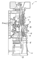
도 2는 본 발명의 제1 실시 형태에 관한 연소기(10)의 확대 단면도이다.
도 3은 본 발명의 제1 실시 형태에 관한 연소기(10)의 주요부 확대 단면도이다.
도 4는 본 발명의 제1 실시 형태에 관한 주요부 확대도로, 도 3에 있어서의 I 화살표도이다.
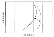
도 5는 본 발명의 제1 실시 형태에 관한 도 3의 단면에 있어서의 예혼합 기체(M)의 연료 농도를 온도로 환산한 것과, 도 3의 단면에 대응하는, 예혼합 기체(M)의 화염면(F)에서의 화염 온도를 나타낸 것이며, 노즐 중심축(P3)으로부터의 직경 방향 위치를 종축, 연료 농도로부터 환산한 온도(온도 환산 농도)를 횡축으로 하고 있다.
도 6은 본 발명의 제1 실시 형태에 관한 연소기(10)의 비교예로, 연소기(10)에 대해 도시한 도 5에 상당한다.
도 7은 본 발명의 제2 실시 형태에 관한 도 3의 단면에 있어서의 예혼합 기체(M)의 연료 농도를 온도로 환산한 것과, 도 3의 단면에 대응하는, 예혼합 기체(M)의 화염면(F)에서의 화염 온도를 나타낸 것이며, 노즐 중심축(P3)으로부터의 직경 방향 위치를 종축, 연료 농도로부터 환산한 온도(온도 환산 농도)를 횡축으로 하고 있다.
도 8은 본 발명의 제2 실시 형태에 관한 연소기(10)의 비교예로, 연소기(10)에 대해 도시한 도 7에 상당한다.
도 9는 본 발명의 제2 실시 형태의 변형예에 관한 메인 노즐을 도시하는 도면으로, 중심축 방향으로부터 본 도면이다.
도 10은 본 발명의 제2 실시 형태의 변형예에 관한 메인 노즐의 개략 구성을 도시하는 정면도이다.
도 11은 본 발명의 제2 실시 형태의 변형예에 관한 메인 노즐을 도시하는 도면으로, 도 10에 있어서의 X-X 단면도이다.
도 12는 본 발명의 제2 실시 형태의 변형예에 관한 메인 노즐을 도시하는 도면으로, 도 10에 있어서의 Y-Y 단면도이다.1 is a schematic structural cross-sectional view showing the overall configuration of a
2 is an enlarged cross-sectional view of a
3 is an enlarged cross-sectional view of a main part of the
Fig. 4 is an enlarged view of the main portion according to the first embodiment of the present invention, and is an I arrow in Fig. 3; Fig.
Fig. 5 is a graph showing the relationship between the fuel concentration of the premixed gas M in the section of Fig. 3 according to the first embodiment of the present invention and the temperature of the premixed gas M The flame temperature on the flame surface F is represented by the ordinate axis in the radial direction from the nozzle central axis P3 and the abscissa axis represents the temperature (temperature converted concentration) converted from the fuel concentration.
Fig. 6 is a comparative example of the
Fig. 7 is a graph showing the relationship between the fuel concentration of the premixed gas M in the cross-section of Fig. 3 according to the second embodiment of the present invention and the temperature of the premixed gas M The flame temperature on the flame surface F is represented by the ordinate axis in the radial direction from the nozzle central axis P3 and the abscissa axis represents the temperature (temperature converted concentration) converted from the fuel concentration.
Fig. 8 is a comparative example of the
9 is a view showing a main nozzle according to a modified example of the second embodiment of the present invention, and is a view seen from the direction of the central axis.
10 is a front view showing a schematic structure of a main nozzle according to a modified example of the second embodiment of the present invention.
Fig. 11 is a cross-sectional view taken along line XX of Fig. 10 showing a main nozzle according to a modified example of the second embodiment of the present invention.
Fig. 12 is a YY cross-sectional view of Fig. 10 showing a main nozzle according to a modification of the second embodiment of the present invention.
〔제1 실시 형태〕[First Embodiment]
이하, 도면을 참조하여, 본 발명의 제1 실시 형태에 대해 설명한다.Hereinafter, a first embodiment of the present invention will be described with reference to the drawings.
도 1은, 본 발명의 실시 형태에 관한 가스 터빈(1)의 전체 구성을 도시하는 개략 구성 단면도이다.1 is a schematic structural cross-sectional view showing the overall configuration of a
도 1에 도시하는 바와 같이, 이 가스 터빈(1)은 압축기(2)와 복수의 연소기(10)와 터빈(3)으로 개략 구성되어 있다.1, the
압축기(2)는, 공기를 작동 유체로서 도입하여 압축 공기[공기(A)]를 생성한다.The compressor (2) introduces air as a working fluid to generate compressed air (air (A)).
복수의 연소기(10)는, 도 1에 도시하는 바와 같이, 압축기(2)의 출구에 연통되어 있고, 압축기(2)로부터 공급된 압축 공기(A)에 연료를 혼합함과 함께 연소시켜 고온 또한 고압의 연소 가스(B)를 발생시킨다.1, the plurality of
터빈(3)은, 연소기(10)로부터 송출된 연소 가스(B)의 열에너지를 로터(1a)의 회전 에너지로 변환한다. 그리고, 이 회전 에너지가 로터(1a)에 연결된 발전기(도시하지 않음)에 전달된다.The
또한, 각 연소기(10)는, 각각의 연소기 중심축(P2)을, 가스 터빈(1)에 있어서의 로터(1a)의 회전 중심축(P1)에 대해 연소기(10)의 입구측이 출구측보다도 직경 방향으로 이격되는 측으로 기울인 상태에서 방사 형상으로 배치되어 있다.Each
도 2는, 연소기(10)의 확대 단면도이다.2 is an enlarged cross-sectional view of the
도 2에 도시하는 바와 같이, 각 연소기(10)는 외통(11)과, 내통(12)과, 메인 노즐(제1 노즐)(14)과, 파일럿 노즐(제2 노즐)(13)과, 미통(15)을 구비하고 있다.2, each combustor 10 includes an
외통(11)은, 그 중심축을 연소기 중심축(P2)에 겹치고 있고, 축 방향 일단부측의 외주로부터 직경 방향 외측으로 연장되는 플랜지(11f)가 차실 케이싱(1b)에 고정되어 있다. 이 외통(11)의 축 방향 타단부측의 기단부(11a)측에는, 메인 노즐(14)에 연료를 공급하는 연료 공급부(10a)와, 메인 노즐(14)을 지지하는 노즐 터브(20)가 배치되어 있다.The
내통(12)은 외통(11)보다도 소직경으로 형성되어 있고, 그 중심축을 연소기 중심축(P2)에 겹치고 있다. 이 내통(12)은, 기단부 개구부(12b)측으로부터 연장된 지지부(12f) 등을 통해 외통(11)에 고정되어 있다.The
이러한 내통(12)은, 도 2에 도시하는 바와 같이, 외통(11)과의 간극이 압축 공기(A)의 유로로 되어 있어, 외통(11)의 기단부(11a)측의 기단부 개구부(12b)로부터 압축 공기(A)가 내부에 도입된다.2, the clearance between the
파일럿 노즐(13)은, 장척 형상으로 형성되어 있고, 연소기 중심축(P2) 상에 배치되어 있다. 이 파일럿 노즐(13)은, 기단부(13b)측이 노즐 스터브(20) 등에 지지되어 있고, 선단(13a)측이 내통(12)에 포위되어 있다. 이러한 파일럿 노즐(13)은 연료 공급부(10a)로부터 기단부(13b)측에 공급된 연료에 의해, 선단(13a)측에 파일럿 불꽃을 형성한다. 또한, 연료 공급부(10a)는 필요에 따라서, 메인 노즐 본체(21)의 기단부(21b)측의 주위에 형성된 연료 공급로(10b)와, 메인 노즐 본체(21)의 기단부(21b)측의 저부에 형성된 연료 공급로(10c)를 구비하는 구성으로 해도 된다.The
메인 노즐(14)은, 내통(12)의 내주를 따라 등피치로 환 형상으로 복수(예를 들어, 8개) 배치되어 있다. 이들 복수의 메인 노즐(14)은, 각각의 노즐 중심축(P3)(도 3 참조)이 연소기(10)의 연소기 중심축(P2)과 평행하게 되도록 배치되어 있다.The
도 3은, 연소기(10)의 주요부 확대 단면도이고, 도 4는 도 3에 있어서의 I 화살표도이다.3 is an enlarged cross-sectional view of a main portion of the
도 3에 도시하는 바와 같이, 각 메인 노즐(14)은 메인 노즐 본체(21)와, 복수의 메인 스월러 날개(22)와, 메인 노즐 통(23)과, 연장관(24)을 구비하고 있다. 또한, 파일럿 노즐(13)은 파일럿 노즐 본체(25)와, 복수의 파일럿 스월러 날개(26)와, 파일럿 노즐 통(27)과, 파일럿 콘(28)을 구비하고 있다.3, each
메인 노즐 본체(21)는, 도 2에 도시하는 바와 같이, 장척 형상으로 형성되어 있고, 노즐 중심축(P3) 상에 위치하고 있다. 이 메인 노즐 본체(21)는, 도 2에 도시하는 바와 같이, 기단부(21b)측이 노즐 스터브(20)에 지지되어 있고, 연료 공급부(10a)와 접속된 연료 유로를 내부에 갖고 있다.As shown in Fig. 2, the
메인 스월러 날개(22)는, 도 3 및 도 4에 도시하는 바와 같이, 메인 노즐 본체(21)의 선단(21a)측의 외주에 방사 형상으로 복수(본 실시 형태에서는, 6개) 배치되어 있고, 이 예혼합 기체(M)의 선회류를 형성한다.As shown in Figs. 3 and 4, the
각 메인 스월러 날개(22)에는, 도 4에 도시하는 바와 같이, 연료 토출부(22A, 22B)가 배치되어 있다.As shown in Fig. 4,
연료 토출부(22A, 22B)는, 메인 스월러 날개(22)의 압력면(22a) 및 부압면(22b)에 형성된 한 쌍의 연료 토출 구멍(22c)에 의해 구성되어 있고, 연료 토출부(22A)가 직경 방향 외측에, 연료 토출부(22B)가 직경 방향 내측에 형성되어 있다.The
연료 토출 구멍(22c)은, 각각 메인 노즐 본체(21)의 연료 유로에 연통되어 있다. 이 연료 토출 구멍(22c)은, 연료 토출부(22A, 22B) 각각에 대해, 압력면(22a)에 형성된 연료 토출 구멍(22c)이 직경 방향 외측에, 부압면(22b)에 형성된 연료 토출 구멍(22c)이 직경 방향 내측에 위치하도록 형성되어 있다.The fuel discharge holes 22c communicate with the fuel flow passages of the
이러한 구성에 의해, 도 3에 도시하는 바와 같이, 연료 토출부(22A, 22B)는, 연료 토출 구멍(22c)으로부터 연료(f)를 토출하여 압축 공기(A)와 연료(f)의 예혼합 기체(M)를 생성한다.3, the
메인 노즐 통(23)은, 그 중심축을 노즐 중심축(P3)과 겹쳐 배치되고, 통 선단 개구(23a) 및 통 기단부 개구(23b)가 각각 축 방향을 향하고 있다. 그리고, 이 메인 노즐 통(23)은, 각 메인 노즐 본체(21)의 선단(21a)과 복수의 메인 스월러 날개(22)를 포위하고 있다.The
연장관(24)은, 축 방향의 관 기단부 개구(24b)측이 메인 노즐 통(23)의 통 선단 개구(23a)측과 접속되어 있다. 이 연장관(24)은, 선단 개구부(선단 출구)(24a)측에 있어서, 관 기단부 개구(24b)측으로부터 관 선단 개구(24a)측으로 진행함에 따라서, 유로 단면이 점차 작아지고 있다.The
이 연장관(24)은, 관 선단 개구(24a)의 직경 방향 외주벽측으로부터 냉각 필름을 위한 냉각 공기(a2)를 유출시킨다.The extension pipe (24) allows the cooling air (a2) for the cooling film to flow out from the radially outer peripheral wall side of the tube front opening (24a).
이러한 메인 노즐(14)은, 파일럿 노즐(13)과 마찬가지로, 메인 노즐 통(23)이나 연장관(24) 등이 위치하는 선단측이 내통(12)에 포위되어 있다.The
파일럿 노즐(13)은, 파일럿 노즐 본체(25)의 선단(25a)측에, 파일럿 노즐 통(27)을 구비하고, 이 파일럿 노즐 통(27)과 파일럿 노즐 본체(25) 사이에 환 형상의 공간이 형성된다. 그리고, 원통 형상의 파일럿 노즐 통(27)과 파일럿 노즐 본체(25) 사이에 파일럿 스월러 날개(26)가 배치되어 있고, 이 파일럿 스월러 날개(26)가 압축 공기(A)의 선회류를 형성한다.The
파일럿 콘(28)은, 파일럿 노즐 통(27)의 통 선단 개구(27a)측에, 기단부 개구(28b)가 접속되어 있다. 이 파일럿 콘(28)은, 기단부 개구(28b)로부터 선단 개구(28a)로 진행함에 따라서, 유로 면적이 점차 커지고 있다.The
또한, 연장관(24)과 파일럿 콘(28)의 간극에는 냉각 공기(a1)의 유로가 형성되어 있고, 이 유로로부터 유출된 냉각 공기(a1)에 의해, 연장관(24)이나 파일럿 콘(28)을 냉각한다.A channel of the cooling air a1 is formed in the gap between the
도 2 및 도 3에 도시하는 바와 같이, 미통(15)은 기단부 개구(15b)가 내통(12)의 선단 개구부(12a)측에 접속됨과 함께, 선단 개구(축 방향 선단)(15a)가 터빈(3)에 연통되어 있다. 이 미통(15)은, 메인 노즐(14)로부터 공급된 예혼합 기체(M)를 연소시켜, 선단 개구(15a)측을 향함에 따라서 직경 방향 외측으로 넓어지는 화염면(F)을 형성한다.2 and 3, the
도 3에 도시하는 바와 같이, 이 미통(15)과 내통(12)의 간극에는, 냉각 공기(a3)의 유로가 형성되어 있고, 이 유로로부터 유입된 냉각 공기(a3)가 미통(15)의 내주면을 따라 흘러 냉각 필름을 형성한다. 또한, 도 3에 도시하는 바와 같이, 내통(12)의 선단 개구부(12a)의 하류측으로부터도 냉각 공기(a4)가 유입된다.3, the flow path of the cooling air a3 is formed in the gap between the
또한, 본 실시 형태에서는, 이 냉각 공기(a1∼a4) 중, 연장관(24)과 파일럿 콘(28)의 간극으로부터 유출되는 냉각 공기(a1)의 영향이 지배적으로 되는 경우에 대해 설명한다.In this embodiment, a case in which the influence of the cooling air a1 flowing out from the gap between the
상술한 바와 같이, 메인 노즐(14)은, 압축 공기(A)와 연료(f)의 예혼합 기체(M)를 내통(12)의 내부에 공급한다. 그때, 메인 노즐(14)은 축 방향에 있어서 화염면(F)이 균일한 온도로 되도록, 그 메인 노즐(14)의 노즐 중심축(P3) 주위로 연료 농도를 변화시켜 예혼합 기체(M)를 공급한다.The
메인 노즐(14)은, 관 선단 개구(24a)에 있어서, 내통(12)의 직경 방향 외측[연소기 중심축(P2)으로부터 이격되는 측]으로 되는 제1 범위(S1)와 비교하여, 내통(12)의 직경 방향 내측으로 되는 제2 범위(S2)의 연료 농도를 상대적으로 높게 한다.The
이 구체적인 구성으로서는, 도 4에 도시하는 바와 같이, 6개의 연료 토출부(22A) 중, 토출된 연료(f)가 제1 범위(S1)에 도달하는 그룹 G1의 연료 토출량을 적게 하고, 토출된 연료(f)가 제2 범위(S2)에 도달하는 그룹 G2의 연료 토출량을 많게 하고 있다.4, among the six
보다 상세하게는, 도 4에 도시하는 바와 같이, 내통(12)의 직경 방향 내측에 위치하는 2개의 연료 토출부(22A) 및 이들 2개의 연료 토출부(22A)에 대해 선회 방향으로 인접하는 1개의 연료 토출부(22A)와(그룹 G1), 나머지 3개의 연료 토출부(22A)(그룹 G2)에서, 연료 토출 구멍(22c)의 개구 면적이 다르다.More specifically, as shown in Fig. 4, two
또한, 6개의 연료 토출부(22B)에 있어서의 각 연료 토출 구멍(22c)의 크기는 동일하다.The sizes of the fuel discharge holes 22c in the six
연료 토출 구멍(22c)의 개구 면적은, 연료 토출부(22B)에 속하는 연료 토출 구멍(22c)의 구멍 직경을 1로 하면, 그룹 G1에 속하는 연료 토출 구멍(22c)의 구멍 직경이 0.9로 설정되고, 그룹 G2에 속하는 연료 토출 구멍(22c)의 구멍 직경이 1.1로 설정되어 있다.The opening area of the
또한, 연료 토출 구멍(22c)의 위치나 수, 및 구멍 직경의 크기는, 관 선단 개구(24a)의 농도 분포에 따라서 정해져 있다.The position and number of the fuel discharge holes 22c and the size of the hole diameter are determined in accordance with the concentration distribution of the
이와 같이, 6개의 연료 토출부(22A)의 연료 토출량이, 메인 노즐(14)의 노즐 중심축(P3) 주위에서 2종류로 나뉘어져 있다. 또한, 동일한 메인 스월러 날개(22)에 있어서, 메인 노즐 본체(21)의 직경 방향 외측의 연료 토출부(22A)와, 내측의 연료 토출부(22B)에서, 연료 토출량이 다르다.Thus, the fuel discharge amount of the six
이러한 구성에 의해, 메인 노즐 본체(21)의 연료 유로에 있어서의 연료(f)에 압력을 작용시키면, 각 연료 토출 구멍(22c)으로부터 개구 면적에 따른 양의 연료(f)가 압축 공기(A)에 토출된다.With this configuration, when a pressure is applied to the fuel f in the fuel passage of the
다음으로, 상술한 연소기(10)의 작용에 대해 설명한다.Next, the operation of the above-described
가스 터빈(1)의 운전을 개시하면, 압축기(2)가 압축 공기(A)를 생성한다. 이 압축 공기(A)는, 도 2에 도시하는 바와 같이, 각 연소기(10)의 내통(12)의 기단부 개구부(12b)로부터 내통(12)의 내부로 유입된다.When the operation of the
내통(12)의 내부에 유입된 압축 공기(A)는, 일부가 파일럿 노즐(13)에 의한 파일럿 불꽃의 연소에 사용되고, 일부가 메인 노즐(14)의 메인 노즐 통(23)에 유입된다.Part of the compressed air A introduced into the
각 연료 토출 구멍(22c)은, 메인 스월러 날개(22)에 유입된 압축 공기(A)에 대해 개구 면적에 따른 양의 연료(f)를 토출한다. 그리고, 토출된 연료(f)와 압축 공기(A)가 메인 스월러 날개(22)에 의해 혼합되어 예혼합 기체(M)가 생성됨과 함께, 예혼합 기체(M)의 선회류가 형성된다.Each
이러한 예혼합 기체(M)는, 연장관(24)의 관 선단 개구(24a)에 도달하였을 때, 제1 범위(S1)의 농도가 상대적으로 낮고, 제2 범위(S2)의 농도가 상대적으로 높아진다.When the preliminary mixture M reaches the tube front opening 24a of the
관 선단 개구(24a)로부터 유출된 예혼합 기체(M)는, 도 3에 도시하는 바와 같이 화염면(F)을 형성한다.The premixed gas M flowing out from the tube end opening 24a forms a flame surface F as shown in Fig.
보다 상세하게는, 예혼합 기체(M)는, 연소기(10)의 연소기 중심축(P2) 방향의 하류측으로 흘러가지만, 내통(12)의 내측[연소기 중심축(P2)측]의 예혼합 기체(M)일수록, 상류 영역에 있어서 직경 방향 내측에서 연소한다. 바꾸어 말하면, 내통(12)의 직경 방향 외측의 예혼합 기체(M)일수록, 보다 하류 영역에 도달함과 함께, 보다 직경 방향 외측에서 연소한다.More specifically, the premixed gas M flows to the downstream side of the
즉, 통 선단 개구(23a)로부터 유출된 예혼합 기체(M)는, 내통(12)의 내측이며, 제1 범위(S1)와 비교하여 연료 농도가 높아진 제2 범위(S2)로부터 먼저 연소한다.That is, the premixed gas M flowing out from the
한편, 예혼합 기체(M)가 하류측으로 흘러가면, 예혼합 기체(M)가 하류 영역으로 흐를 때까지의 동안에 제2 범위(S2)에 냉각 공기(a1)가 혼입되고, 관 선단 개구(24a)에서 상대적으로 높았던 연료 농도가 희박해져 제1 범위(S1)와 동일 정도의 연료 농도로 된다.On the other hand, when the premixed gas M flows downward, the cooling air a1 is mixed into the second range S2 until the premixed gas M flows into the downstream region, and the
이와 같이 하여, 예혼합 기체(M)가 연소하는 범위가 내통(12)의 내측으로부터 직경 방향 외측으로 순차 옮겨 가, 축 방향에 있어서 대략 동일한 연료 농도로 된 예혼합 기체(M)에 의해 화염면(F)이 형성된다. 이와 같이 하여 형성된 화염면(F)은, 축 방향에 있어서 화염 온도가 균일적으로 되어, NOx의 발생이 근소한 것으로 된다.In this way, the range in which the premixed gas M is burned is successively transferred from the inner side of the
이상 설명한 바와 같이, 연소기(10)에 의하면, 축 방향에 있어서 화염면(F)이 균일한 온도로 되도록, 각 메인 노즐(14)이 그 노즐 중심축(P3) 주위로 연료 농도를 변화시켜 예혼합 기체(M)를 공급하므로, 축 방향에 걸쳐 예혼합 기체(M)의 연료 농도의 치우침을 완화하는 것이 가능하다. 이에 의해, 예혼합 기체(M)에 냉각 공기(a1)가 혼입되었다고 해도, 축 방향에 걸쳐 균일적인 연료 농도의 예혼합 기체(M)에 의해 화염면(F)이 형성되게 되어, 축 방향에 있어서 화염면(F)이 불균일한 온도에서 연소되는 것을 억제함과 함께 NOx의 발생을 억제할 수 있다.As described above, according to the
도 5는, 메인 노즐(14)의 관 선단 개구(24a)에 있어서의 예혼합 기체(M)의 연료 농도를 온도로 환산한 것과, 도 3의 단면에 대응하는, 예혼합 기체(M)의 화염면(F)에서의 화염 온도를 나타낸 것이며, 노즐 중심축(P3)으로부터의 직경 방향 위치를 종축, 연료 농도로부터 환산한 온도(온도 환산 농도)를 횡축으로 하고 있다. 또한, 도 5에 있어서, 실선이 예혼합 기체(M)의 화염면(F)에서의 화염 온도, 파선이 관 선단 개구(24a)에 있어서의 예혼합 기체(M)의 연료 농도를 온도로 환산한 값이다.5 is a graph showing the relationship between the fuel concentration of the premixed gas M at the tube front opening 24a of the
또한, 도 6은 연료 토출 구멍(22c)의 개구 면적을 노즐 중심축(P3)의 주위에 있어서 모두 동일[연료 토출부(22A)의 연료 토출 구멍(22c)이 연료 토출부(22B)의 연료 토출 구멍(22c)과 동일한 구멍 직경]하게 한 경우의 비교예이다.6 shows an example in which the opening area of the
비교예와 같이 연료 토출 구멍(22c)의 개구 면적을 노즐 중심축(P3)의 주위에 있어서 모두 동일한 것으로 하고, 관 선단 개구(24a)에 있어서의 농도 분포를 대체로 균일적인 것으로 하면, 도 6에 실선으로 나타내는 바와 같이, 화염면(F)에서는 내통(12)의 직경 방향 외측에서 온도 피크 R(최고 화염 온도)가 발생하고, 이 부분에서 국소적으로 화염 온도가 높아진다. 한편, 온도 피크 R로부터 직경 방향 내측으로 됨에 따라서, 화염 온도가 급격하게 저하된다.If the opening area of the
이것은, 냉각 공기(a1)에 의해, 직경 방향 내측의 예혼합 기체(M)의 연료 농도가 저하되기 쉽기 때문이다.This is because the fuel concentration of the premixed gas M in the radially inward direction is likely to be lowered by the cooling air a1.
한편, 본 발명의 연소기(10)에서는, 비교예에 대해 도 5에 나타내는 바와 같이, 관 선단 개구(24a)에 있어서의 농도 분포는 균일하지 않고, 직경 방향 외측에 대해 직경 방향 내측의 농도가 상대적으로 높게 되어 있다. 또한, 본 발명의 연소기(10)에서는, 비교예에 대해 화염면(F)에 있어서의 예혼합 기체의 화염 온도는 대체로 균일하게 되어 있다. 또한, 본 발명의 연소기(10)에서는, 비교예와 비교하여, 도 5에 실선으로 나타내는 바와 같이, 온도 피크 R이 낮게 되어 있다. 이와 같이, 연소기(10)에서는, 전체적으로 보아 연소 온도가 균일적인 것으로 되어 있어, 국소적인 화염 온도의 상승을 저감시킬 수 있으므로, NOx의 발생이 충분히 억제된다.On the other hand, in the
또한, 메인 노즐(14)의 관 선단 개구(24a)에 있어서, 내통(12)의 직경 방향 외측으로 되는 제1 범위(S1)와 비교하여, 내통(12)의 직경 방향 내측의 제2 범위(S2)에서의 연료 농도를 상대적으로 높게 한다. 즉, 상대적으로 연료 농도가 낮아지기 어렵고 하류측에서 연소하는 제1 범위(S1)의 연료 농도를 낮게 설정하고, 상대적으로 연료 농도가 낮아지기 쉽고 상류측에서 연소하는 제2 범위(S2)의 연료 농도를 높게 설정한다. 이에 의해, 비교적 간단한 구성으로, 화염면(F)에 도달하는 예혼합 기체(M)의 연료 농도를 축 방향에 있어서 균일적으로 할 수 있다.Compared to the first range S1 which is radially outward of the
또한, 6개의 메인 스월러 날개(22)에 각각 형성된 연료 토출부(22A)의 연료 토출량이 노즐 중심축(P3) 주위에서 2종류로 나뉘어져 있으므로, 관 선단 개구(24a)로부터 유출된 후에 빠른 단계에서 연소되기 쉬운 제2 범위(S2)와, 하류 영역까지 흘러 늦게 연소되는 제1 범위(S1)에 대응시켜, 노즐 중심축(P3) 주위로 예혼합 기체(M)의 연료 농도를 용이하게 변화시킬 수 있다.Since the fuel discharge amount of the
또한, 동일한 메인 스월러 날개(22)에 있어서 메인 노즐(14)의 직경 방향의 외측의 연료 토출부(22A)와, 내측의 연료 토출부(22B)에서 연료 토출량을 변화시키고 있으므로, 예혼합 기체(M)의 연료 농도를 용이하고 또한 적절하게 직경 방향으로 조정할 수 있다.Since the amount of fuel discharged from the
또한, 연료 토출 구멍(22c)의 개구 면적이 다르므로, 비교적 간소한 구성으로 연료 토출량을 변화시켜, 예혼합 기체(M)의 연료 농도를 변화시킬 수 있다.Further, since the opening area of the
또한, 가스 터빈(1)에 의하면, 연소기(10)를 구비하므로, NOx의 발생이 억제된 구성으로 할 수 있다.Further, according to the
〔제2 실시 형태〕[Second embodiment]
제1 실시 형태에서는, 연장관(24)과 파일럿 콘(28)의 간극으로부터 유출되는 냉각 공기(a1)의 영향이 지배적으로 되는 경우에 대해 설명하였지만, 제2 실시 형태에서는, 연장관(24)의 관 선단 개구(24a)의 직경 방향 외주벽측으로부터의 냉각 필름을 위한 냉각 공기(a2), 미통(15)과 내통(12)의 간극의 유로로부터 유입된 냉각 공기(a3), 내통(12)의 선단 개구부(12a)의 하류측으로부터 유입된 냉각 공기(a4) 등의, 내통의 직경 방향 외측의 냉각 공기의 영향이 지배적으로 되는 경우에 대해 설명한다. 이로 인해, 제1 실시 형태와 마찬가지의 구성에 대해서는 기재를 생략한다.The influence of the cooling air a1 flowing out from the gap between the
본 실시 형태에서는, 메인 노즐(14)은, 관 선단 개구(24a)에 있어서, 내통(12)의 직경 방향 내측[연소기 중심축(P2)에 접근하는 측]으로 되는 제2 범위(S2)와 비교하여, 내통(12)의 직경 방향 외측으로 되는 제1 범위(S1)의 연료 농도를 상대적으로 높게 한다.In the present embodiment, the
이 구체적인 구성으로서는, 도 4에 있어서, 6개의 연료 토출부(22A) 중, 토출된 연료(f)가 제1 범위(S1)에 도달하는 그룹 G1의 연료 토출량을 많게 하고, 토출된 연료(f)가 제2 범위(S2)에 도달하는 그룹 G2의 연료 토출량을 적게 하고 있다.4, the fuel discharge amount of the group G1 in which the discharged fuel f reaches the first range S1 among the six
또한, 연료 토출 구멍(22c)의 위치나 수, 및 구멍 직경의 크기는, 관 선단 개구(24a)의 농도 분포에 따라서 정해져 있다.The position and number of the fuel discharge holes 22c and the size of the hole diameter are determined in accordance with the concentration distribution of the
다음으로, 상술한 연소기(10)의 작용에 대해 설명한다.Next, the operation of the above-described
예혼합 기체(M)는, 연장관(24)의 관 선단 개구(24a)에 도달하였을 때, 제1 범위(S1)의 농도가 상대적으로 높고, 제2 범위(S2)의 농도가 상대적으로 낮아진다.The concentration of the preliminary mixture M in the first range S1 is relatively high and the concentration in the second range S2 is relatively low when the preliminary mixture M reaches the tube front opening 24a of the
즉, 통 선단 개구(23a)로부터 유출된 예혼합 기체(M)는, 내통(12)의 내측이며, 제1 범위(S1)와 비교하여 연료 농도가 낮아진 제2 범위(S2)로부터 먼저 연소된다.That is, the premixed gas M flowing out from the
한편, 예혼합 기체(M)가 하류측으로 흘러가면, 예혼합 기체(M)가 하류 영역으로 흐를 때까지의 동안에 제1 범위(S1)에 냉각 공기(a2∼a4)가 혼입되고, 관 선단 개구(24a)에서 상대적으로 높았던 연료 농도가 희박해져 제2 범위(S2)와 동일 정도의 연료 농도로 된다.On the other hand, when the premixed gas M flows downward, the cooling air a2 to a4 is mixed into the first range S1 until the premixed gas M flows into the downstream region, The fuel concentration that was relatively high in the
이와 같이 하여, 예혼합 기체(M)가 연소되는 범위가 내통(12)의 내측으로부터 직경 방향 외측으로 순차 옮겨 가, 축 방향에 있어서 대략 동일한 연료 농도로 된 예혼합 기체(M)에 의해 화염면(F)이 형성된다.In this manner, the range in which the premixed gas M is burnt is sequentially transferred from the inner side of the
이와 같이 하여 형성된 화염면(F)은, 축 방향에 있어서 화염 온도가 균일적으로 되어, NOx의 발생이 근소한 것으로 된다.The flame surface F formed in this way becomes uniform in flame temperature in the axial direction, and the generation of NOx becomes small.
이상 설명한 바와 같이, 연소기(10)에 의하면, 축 방향에 있어서 화염면(F)이 균일한 온도로 되도록, 각 메인 노즐(14)이 그 노즐 중심축(P3) 주위로 연료 농도를 변화시켜 예혼합 기체(M)를 공급하므로, 축 방향에 걸쳐 예혼합 기체(M)의 연료 농도의 치우침을 완화하는 것이 가능하다.As described above, according to the
이에 의해, 예혼합 기체(M)에 냉각 공기(a2∼a4)가 혼입되었다고 해도, 축 방향에 걸쳐 균일적인 연료 농도의 예혼합 기체(M)에 의해 화염면(F)이 형성되게 되어, 축 방향에 있어서 화염면(F)이 불균일한 온도에서 연소되는 것을 억제함과 함께 NOx의 발생을 억제할 수 있다.Thereby, even if the cooling air (a2 to a4) is mixed in the premixed gas M, the flame surface F is formed by the premixed gas M having a uniform fuel concentration in the axial direction, It is possible to suppress the combustion of the flame surface F at a non-uniform temperature and to suppress the generation of NOx.
도 7은, 관 선단 개구(24a)에 있어서의 직경 방향의 예혼합 기체(M)의 연료 농도를 온도로 환산한 것과, 대응하는 예혼합 기체(M)의 화염면(F)에서의 화염 온도를 나타낸 것이며, 실선이 예혼합 기체(M)의 화염면(F)에서의 화염 온도, 파선이 관 선단 개구(24a)에 있어서의 예혼합 기체(M)의 연료 농도를 온도로 환산한 값이다.7 is a graph showing the relationship between the fuel concentration of the premixed gas M in the radial direction at the
또한, 도 8은 연료 토출 구멍(22c)의 개구 면적을 노즐 중심축(P3)의 주위에 있어서 모두 동일[연료 토출부(22A)의 연료 토출 구멍(22c)이 연료 토출부(22B)의 연료 토출 구멍(22c)과 동일한 구멍 직경]하게 한 경우의 비교예이다.8 shows a state in which the opening area of the
비교예와 같이 연료 토출 구멍(22c)의 개구 면적을 노즐 중심축(P3)의 주위에 있어서 모두 동일한 것으로 하고, 관 선단 개구(24a)에 있어서의 농도 분포를 대체로 균일적인 것으로 하면, 도 8에 실선으로 나타내는 바와 같이, 화염면(F)에서는 내통(12)의 직경 방향 외측에서 온도 피크 R(최고 화염 온도)이 발생하고, 이 부분에서 국소적으로 화염 온도가 높아진다. 한편, 온도 피크 R로부터 직경 방향 외측으로 됨에 따라서, 화염 온도가 급격하게 저하된다.If the opening area of the
이것은, 냉각 공기(a2∼a4)에 의해, 직경 방향 외측의 예혼합 기체(M)의 연료 농도가 저하되기 쉽기 때문이다.This is because the fuel concentration of the premixed gas M on the outer side in the radial direction is likely to be lowered by the cooling air a2 to a4.
한편, 본 발명의 연소기(10)에서는, 비교예에 대해, 도 7에 나타내는 바와 같이, 관 선단 개구(24a)에 있어서의 농도 분포는 균일하지 않고, 직경 방향 내측에 대해 직경 방향 외측의 농도가 상대적으로 높게 되어 있다. 또한, 본 발명의 연소기(10)에서는, 비교예에 대해, 화염면(F)에 있어서의 예혼합 기체의 화염 온도는 대체로 균일하게 되어 있다. 또한, 본 발명의 연소기(10)에서는, 비교예와 비교하여, 도 7에 실선으로 나타내는 바와 같이, 온도 피크 R이 낮게 되어 있다. 이와 같이, 연소기(10)에서는, 전체적으로 보아 연소 온도가 균일적인 것으로 되어 있어, 국소적인 화염 온도의 상승을 저감시킬 수 있으므로, NOx의 발생이 충분히 억제된다.On the other hand, in the
또한, 메인 노즐(14)의 관 선단 개구(24a)에 있어서, 내통(12)의 직경 방향 내측으로 되는 제2 범위(S2)와 비교하여, 내통(12)의 직경 방향 외측의 제1 범위(S1)에서의 연료 농도를 상대적으로 높게 한다. 즉, 상대적으로 연료 농도가 낮아지기 쉽고 하류측에서 연소되는 제1 범위(S1)의 연료 농도를 높게 설정하고, 상대적으로 연료 농도가 낮아지기 어렵고 상류측에서 연소되는 제2 범위(S2)의 연료 농도를 낮게 설정한다.Compared to the second range S2 which is radially inward of the
이에 의해, 비교적 간단한 구성으로, 화염면(F)에 도달하는 예혼합 기체(M)의 연료 농도를 축 방향에 있어서 균일적으로 할 수 있다.Thereby, the fuel concentration of the premixed gas M reaching the flame surface F can be made uniform in the axial direction with a relatively simple structure.
또한, 상술한 실시 형태에 있어서 나타낸 동작 순서, 혹은 각 구성 부재의 여러 형상이나 조합 등은 일례이며, 본 발명의 주지로부터 벗어나지 않는 범위에 있어서 설계 요구 등에 기초하여 다양하게 변경 가능하다.In addition, the operation sequence shown in the above-described embodiment, or the various shapes and combinations of the respective constituent members is merely an example, and can be variously changed based on design requirements and the like without departing from the gist of the present invention.
예를 들면, 상술한 실시 형태에서는, 연료 토출 구멍(22c)의 개구 면적을 다르게 함으로써, 연료 토출량을 다르게 하여 연료 농도를 변화시켰다. 그러나, 이 대신에 예를 들어, 각 연료 토출 구멍(22c)의 수량이나 각 연료 토출 구멍(22c)에 대한 공급 압력을 변화시켜 연료 토출량을 다르게 함으로써, 연료 농도를 변화시켜도 된다. 혹은, 이들을 적절하게 조합하여 연료 농도를 변화시켜도 된다.For example, in the above-described embodiment, by changing the opening area of the
이하, 도 9 내지 도 12를 참조하여, 본 발명의 제1 실시 형태 또는 제2 실시 형태의 변형예에 대해 설명한다.Hereinafter, a modification of the first embodiment or the second embodiment of the present invention will be described with reference to Figs. 9 to 12. Fig.
도 9는, 메인 노즐(14)을 중심축 방향 선단측으로부터 본 도면이다. 또한, 도 10은, 메인 노즐(14)의 개략 구성을 도시하는 정면도이고, 도 11, 도 12는, 각각 도 10에 있어서의 메인 노즐(14)의 X-X 단면, Y-Y 단면도를 도시하고 있다.9 is a view showing the
이 변형예는, 도 9에 도시하는 바와 같이, 메인 노즐(14)이, 서로 독립된 제1 연료 공급 계통과 제2 연료 공급 계통을 구비하고 있고, 메인 노즐 본체(22)가, 제1 연료 공급 계통에 연통되고 제1 압력 영역(30A)(그물 형상부)에 속하는 연료 토출 구멍(22c)과, 제2 연료 공급 계통에 연통되고 제2 압력 영역(30B)에 속하는 연료 토출 구멍(22c)을 갖고 있다.9, the
제1 연료 공급 계통 및 제2 연료 공급 계통에 있어서의 연료(f)의 공급 압력을 조정함으로써, 제1 압력 영역(30A)의 연료 토출 구멍(22c)으로부터 토출되는 연료(f)의 토출량과, 제2 압력 영역(30B)의 연료 토출 구멍(22c)으로부터 토출되는 연료(f)의 토출량을, 각각 조정 가능하게 되어 있다. 그 밖에는 상기 제1 실시 형태 또는 제2 실시 형태와 마찬가지이므로, 동일한 부호를 부여하여 설명을 생략한다.By adjusting the supply pressure of the fuel f in the first fuel supply system and the second fuel supply system, the discharge amount of the fuel f discharged from the
구체적으로는, 메인 노즐 본체(21)는, 도 9 및 도 10에 도시하는 바와 같이, 메인 노즐 본체(21)의 선단(21a)측의 외주에 방사 형상으로 복수(본 실시 형태에서는, 6개) 배치된 각 메인 스월러 날개(22) 중, 예를 들어 3개가 제1 압력 영역(30A)에 속하고, 나머지에 3개가 제2 압력 영역(30B)에 속해 있다.Specifically, as shown in Figs. 9 and 10, the
또한, 제1 압력 영역(30A)은 제1 범위(S1)와 대응하는 그룹 G1을, 제2 압력 영역(30B)은 제2 범위(S2)와 대응하는 그룹 G2를 포함하여 구성되어 있다.The
또한, 연료 토출 구멍(22c)의 위치나 수, 및 구멍 직경의 크기는, 관 선단 개구(24a)의 농도 분포에 따라서 설정할 수 있다.The position and number of the fuel discharge holes 22c and the size of the hole diameter can be set in accordance with the concentration distribution of the
각 메인 스월러 날개(22)는, 도 9, 도 10에 도시하는 바와 같이, 예를 들어 압력면(22a), 부압면(22b)에, 각각 2개씩 연료 토출 구멍(22c)이 형성되어 있고, 압력면(22a)에 형성된 연료 토출 구멍(22c)이 부압면(22b)에 형성된 연료 토출 구멍(22c)보다도 상대적으로 직경 방향 외측에 배치되어 있다.As shown in Figs. 9 and 10, for example, two fuel discharge holes 22c are formed on the
여기서, 각 메인 스월러 날개(22)의 압력면(22a) 및 부압면(22b)에 있어서, 각각 직경 방향 외측에 위치된 한 쌍의 연료 토출 구멍(22c)은 연료 토출부(22A)를 구성하고 있다.A pair of
또한, 각 메인 스월러 날개(22)의 압력면(22a) 및 부압면(22b)에 있어서, 각각 직경 방향 내측에 위치된 한 쌍의 연료 토출 구멍(22c)은 연료 토출부(22B)를 구성하고 있다.A pair of
메인 노즐 본체(21)는, 도 10에 도시하는 바와 같이, 제1 연료 공급 계통을 구성하는 제1 연료 공급로(31)와, 제2 연료 공급 계통을 구성하는 제2 연료 공급로(32)를 내부에 갖고 있고, 제1 연료 공급 계통 및 제2 연료 공급 계통은 압력적으로 독립되어 있고, 연료 공급부(10a)와 접속되어 있다.10, the
제1 연료 공급로(31)는, 예를 들어 제1 연료 공급구(31A)와, 제1 연료 유로(31B)와, 연료 저류부(31C)와, 제1 분기로(31D)를 구비하고, 제1 연료 공급구(31A)는 메인 노즐 본체(21)의 측부에 형성되고, 연료 저류부(31C)는 제1 분기로(31D)를 통해 각 연료 토출 구멍(22c)으로 분기되어 있다.The first
또한, 제2 연료 공급로(32)는, 예를 들어 제2 연료 공급구(32A)와, 제2 연료 유로(32B)와, 연료 저류부(32C)와, 제2 분기로(32D)를 구비하고, 제2 연료 공급구(32A)는 메인 노즐 본체(21)의 기단부(21b)측의 단부면에 형성되고, 연료 저류부(32C)는 제2 분기로(32D)를 통해 각 연료 토출 구멍(22c)으로 분기되어 있다.The second
연료 저류부(31C)와 연료 저류부(32C)는, 도 10, 도 12에 도시하는 바와 같이, 메인 노즐 본체(21) 내에 주위벽부(21F)에 둘러싸여 인접하여 배치되고, 연료 저류부(31C)와 연료 저류부(32C)는 구획벽부(21G)에 의해 구획되어 압력적으로 서로 독립되어 있다.As shown in Figs. 10 and 12, the
또한, 연료 저류부(31C) 및 연료 저류부(32C)를 설치함으로써, 제1 압력 영역(30A)에 속하는 연료 토출 구멍(22c)에 공급하는 연료(f)의 유량 및 제2 압력 영역(30B)에 속하는 연료 토출 구멍(22c)에 공급하는 연료(f)의 유량을 안정시킴과 함께, 제1 연료 유로(31B) 및 제2 연료 유로(32B)와 대응하는 각 연료 토출 구멍(22c)의 연통을 용이하게 행할 수 있다.The flow rate of the fuel f supplied to the
또한, 이 변형예에서는, 도 2에 도시하는 바와 같이, 제1 연료 공급구(31A)는, 연료 공급부(10a)로부터 연통되어 메인 노즐 본체(21)의 기단부(21b)측의 주위에 형성된 연료 공급로(10b)로부터 연료(f)가 공급되고, 제2 연료 공급구(32A)는, 연료 공급부(10a)로부터 연통되어 메인 노즐 본체(21)의 기단부(21b)측의 저부에 형성된 연료 공급로(10c)로부터 연료(f)가 공급되도록 되어 있다.2, the first
이 실시 형태에 있어서, 연료 공급부(10a)는, 예를 들어 제1 연료 공급 계통 및 제2 연료 공급 계통에 있어서의 연료(f)의 공급 압력 등의 파라미터의 설정을 조정하여, 제1 연료 공급로(31) 및 제2 연료 공급로(32)에 공급하는 연료(f)의 유량을 조정하도록 되어 있다.In this embodiment, the
즉, 이 변형예에서는, 제1 연료 공급 계통 및 제1 연료 공급 계통과 독립된 제2 연료 공급 계통에 의해 연료(f)를 공급하고, 제1 연료 공급 계통 및 제2 연료 공급 계통의 공급 압력을 개별로 제어함으로써, 제1 연료 공급 계통 및 제2 연료 공급 계통의 연료(f)의 유량, 나아가서는, 제1 압력 영역(30A) 및 제2 압력 영역(30B)에 속하는 연료 토출 구멍(22c)으로부터의 연료(f)의 토출량을 조정하도록 되어 있다.That is, in this modification, the fuel (f) is supplied by the first fuel supply system and the second fuel supply system independent of the first fuel supply system, and the supply pressure of the first fuel supply system and the second fuel supply system The fuel injection holes 22c belonging to the
예를 들어, 제1 압력 영역(30A)에 속하는 연료 토출 구멍(22c)의 공급 압력을, 제2 압력 영역(30B)에 속하는 연료 토출 구멍(22c)보다도 높게 함으로써, 그룹 G1에 속하는 연료 토출 구멍(22c)은 그룹 G2에 속하는 연료 토출 구멍(22c)보다도 상대적으로 다량의 연료(f)가 토출되고, 이에 의해, 예혼합 기체의 연료 농도는, 내통(12)의 제1 범위(S1)가 제2 범위(S2)보다도 높아지도록 되어 있다.For example, by making the supply pressure of the
또한, 상술한 실시 형태에 있어서 나타낸 동작 순서, 혹은 각 구성 부재의 여러 형상이나 조합 등은 일례이며, 본 발명의 주지로부터 벗어나지 않는 범위에 있어서 설계 요구 등에 기초하여 다양한 변경이 가능하다.In addition, the operation sequence shown in the above-described embodiment, or various shapes or combinations of the respective constituent members is merely an example, and various modifications can be made based on design requirements and the like without departing from the gist of the present invention.
예를 들어, 상기 실시 형태에 있어서는, 내통(12)의 직경 방향 내측이 제1 범위(S1)로 되고, 내통(12)의 직경 방향 외측이 제2 범위(S2)로 되는 경우에 대해 설명하였지만, 예를 들어 제1 범위(S1)가 내통(12)의 직경 방향 외측의 일부로 되거나, 또는 제2 범위(S2)가 내통(12)의 직경 방향 내측의 일부로 되어도 되고, 제1 범위(S1) 및 제2 범위(S2)가, 내통(12)의 직경 방향 외측 및 직경 방향 내측의 각각 일부를 이루는 구성으로 해도 된다.For example, in the above embodiment, the case where the radially inner side of the
또한, 예를 들어 상기 실시 형태에 있어서는, 메인 노즐(14)이, 제1 범위(S1)와 대응하는 제1 압력 영역(30A)에 속하는 연료 토출 구멍(22c)과, 제2 범위(S2)와 대응하는 제2 압력 영역(30B)에 속하는 연료 토출 구멍(22c)의 2종류의 연료 토출 구멍(22c)을 구비하는 경우에 대해 설명하였지만, 이것에 한정되는 것은 아니다.In the above embodiment, for example, the
예를 들어, 각 메인 노즐(14)에서 생성된 예혼합 기체(M)의 내통(12)의 직경 방향 외측의 영역이 제1 범위(S1)를 포함하는 복수의 영역으로 구분되거나, 또는 제1 범위(S1)가 복수의 다른 연료 농도의 영역으로 구분됨으로써, 복수의 연료 농도로 이루어지는 예혼합 기체를 내통(12)의 직경 방향 외측에 공급하는 경우 등에 있어서, 내통(12)의 직경 방향 외측과 대응하고 있는 연료 토출 구멍(22c)을 제1 압력 영역(30A)에 더하여, 제1 압력 영역(30A)과 독립된 개별의 연료 공급 계통에 연통하는 구성으로 해도 된다.For example, the radially outer region of the
또한, 예를 들어 각 메인 노즐(14)에서 생성된 예혼합 기체(M)의 내통(12)의 직경 방향 내측의 영역이 제2 범위(S2)를 포함하는 복수의 영역으로 구분되거나, 또는 제2 범위(S2)가 복수의 서로 다른 연료 농도의 영역으로 구분됨으로써, 복수의 연료 농도로 이루어지는 예혼합 기체를 내통(12)의 직경 방향 내측에 공급하는 경우 등에 있어서, 내통(12)의 직경 방향 내측과 대응하고 있는 연료 토출 구멍(22c)을 제2 압력 영역(30B)에 더하여, 제2 압력 영역(30B)과 독립된 개별의 연료 공급 계통에 연통하는 구성으로 해도 된다.For example, the radially inner region of the
또한, 내통(12)의 직경 방향 외측 및 직경 방향 내측의 양쪽에, 각각 복수의 독립된 연료 공급이 설치되어 있어도 된다.A plurality of independent fuel supplies may be provided on both the radially outer side and the radially inner side of the
또한, 상기 실시 형태에 있어서는, 메인 노즐(14)이 그룹 G1에 속하는 3개의 메인 스월러 날개(22)와 그룹 G2에 속하는 메인 스월러 날개(22)를 구비하고, 제1 압력 영역(30A) 및 제2 압력 영역(30B)에 속하는 각 메인 스월러 날개(22)에, 각각 4개의 제1 연료 토출 구멍(22c)이 형성되어 있는 경우에 대해 설명하였지만, 이것에 한정되는 것은 아니다.In the above embodiment, the
예를 들어, 메인 노즐(14)이 구비하는 메인 스월러 날개(22)의 수, 그룹 G1 및 그룹 G2와 대응하는 메인 스월러 날개(22)의 수나, 제1 압력 영역(30A) 및 제2 압력 영역(30B)와 대응하는 메인 스월러 날개(22)의 수는 임의로 설정할 수 있다.For example, the number of the
또한, 각각의 메인 스월러 날개(22)에 형성되는 연료 토출 구멍(22c) 수에 대해서도 임의로 설정할 수 있다.The number of the
또한, 상기 실시 형태에 있어서는, 메인 노즐(14)이 6개의 메인 스월러 날개(22)를 구비하는 경우에 대해 설명하였지만, 예를 들어 메인 노즐(14)이 메인 스월러 날개(22)를 구비하지 않는 구성으로 해도 된다.Although the
또한, 상기 실시 형태에 있어서는, 제1 압력 영역(30A)에 속하는 연료 토출 구멍(22c)과, 제2 압력 영역(30B)에 속하는 연료 토출 구멍(22c)은, 동일수이며 배치가 서로 대응하고, 각각의 개구 면적이 동일하게 되는 경우에 대해 설명하였지만, 예를 들어 제1 압력 영역(30A)에 속하는 연료 토출 구멍(22c)과, 제2 압력 영역(30B)에 속하는 연료 토출 구멍(22c)의 수, 배치, 수, 개구 면적 중 어느 하나 또는 모두 다른 설정으로 해도 된다.In the above embodiment, the fuel discharge holes 22c belonging to the
또한, 상기 실시 형태에 있어서는, 제1 압력 영역(30A)이 제1 연료 계통에 접속되고, 제2 압력 영역(30B)이 제2 연료 계통에 접속되어, 제1 연료 계통, 제2 연료 계통의 압력 등의 파라미터를 제어함으로써, 제1 압력 영역(30A)과 제2 압력 영역(30B)에 속하는 각 연료 토출 구멍(22c)으로부터 토출되는 연료(f)의 토출량을 조정하는 경우에 대해 설명하였지만, 예를 들어 제1 연료 공급구(31A), 제2 연료 공급구(32A)나 제1 연료 유로(31B), 제2 연료 유로(32B) 등, 각 연료 공급 계통의 유로 면적이나 유로 저항 등의 설정에 의해, 각 연료 공급 계통이 공급하는 연료(f)의 유량을 조정하는 구성으로 해도 된다.In the above embodiment, the
또한, 상기 실시 형태에 있어서는, 제1 연료 공급로(31)가, 제1 연료 공급구(31A)와, 제1 연료 유로(31B)와, 연료 저류부(31C)와, 제1 분기로(31D)를 구비하는 경우에 대해 설명하였지만, 상기 구성에 한정되지 않는 것은, 물론이다. 제2 연료 공급로(32)에 대해서도 마찬가지이다.In the above embodiment, the first
또한, 제1 압력 영역(30A) 및 제2 압력 영역(30B)에 속하는 각 연료 토출 구멍(22c)의 수, 개구 면적의 설정에 의해 연료(f)의 공급량을 조정해도 된다.The supply amount of the fuel f may be adjusted by setting the number of the fuel discharge holes 22c belonging to the
또한, 이들을 적절하게 조합하여 연료 농도를 변화시켜도 된다.The fuel concentration may be changed by appropriately combining these.
또한, 상술한 실시 형태에서는, 내통(12)의 내주면을 따라 간격을 두고 메인 노즐(14)이 배치되는 연소기(10)에 있어서, 연소기 중심축(P2) 상에 배치되는 파일럿 노즐(13)에 의해 파일럿 불꽃을 형성하고, 이에 의해 메인 노즐(14)로부터의 예혼합 기체에 착화하여 예혼합 연소를 행하는 구성에 대해 나타냈지만, 이 구성에 한정되지 않는다. 예를 들어, 내통의 내주면을 따라 간격을 두고 배치되는 복수의 제1 노즐과, 연소기 중심축 상에 배치되는 제2 노즐을 구비하고, 상기 제1과 제2 노즐이 각각 독립되어 예혼합 연소가 가능한 연소기에 있어서도 본 발명을 적용하는 것이 가능하다.In the above-described embodiment, in the
본 발명에 관한 연소기에 의하면, NOx의 발생을 억제할 수 있다.According to the combustor of the present invention, the generation of NOx can be suppressed.
본 발명에 관한 가스 터빈에 의하면, NOx의 발생이 억제된 가스 터빈을 구성할 수 있다.According to the gas turbine of the present invention, it is possible to constitute a gas turbine in which the generation of NOx is suppressed.
1 : 가스 터빈
10 : 연소기
12 : 내통
14 : 메인 노즐(제1 노즐)
15 : 미통
15a : 선단 개구(축 방향 선단)
15b : 기단부 개구(기단부)
22 : 메인 스월러 날개(스월러 날개)
22A, 22B : 연료 토출부
22c : 연료 토출 구멍
24a : 관 선단 개구(선단 출구)
P2 : 연소기 중심축
P3 : 노즐 중심축(메인 노즐의 중심축)
S1 : 제1 범위
S2 : 제2 범위
A : 압축 공기(공기)
F : 화염면
M : 예혼합 기체
f : 연료1: Gas Turbine
10: Combustor
12: My heart
14: main nozzle (first nozzle)
15: Beverage
15a: tip opening (axial leading end)
15b: base end opening (base end)
22: Main swallower wing (swallow wing)
22A and 22B:
22c: fuel discharge hole
24a: tube end opening (end exit)
P2: central axis of the combustor
P3: nozzle central axis (central axis of main nozzle)
S1: 1st range
S2: 2nd range
A: Compressed air (air)
F: Flame side
M: Premixed gas
f: fuel
Claims (10)
상기 내통의 축 방향으로 연장됨과 함께 상기 내통의 내주를 따라 간격을 두고 복수 설치되고, 각각 상기 공기와 연료의 예혼합 기체를 상기 내통의 내부에 공급하는 제1 노즐과,
상기 내통이 기단부에 접속됨과 함께 상기 제1 노즐로부터 공급된 상기 예혼합 기체를 연소시켜 화염면을 형성하는 미통을 구비하고,
상기 각 제1 노즐은, 축 방향에 있어서 상기 화염면이 균일한 온도로 되도록, 그 제1 노즐의 중심축 주위로 연료 농도를 변화시켜 상기 예혼합 기체를 공급하는, 연소기.An inner passage through which air is supplied from the outside,
A first nozzle extending in the axial direction of the inner cylinder and spaced apart along the inner periphery of the inner cylinder and supplying a premixed gas mixture of the air and the fuel to the inside of the inner cylinder,
Wherein the inner cylinder is connected to the proximal end and the pre-mix gas supplied from the first nozzle is burned to form a flame surface,
Wherein each of the first nozzles supplies the premixed gas by varying a fuel concentration around a central axis of the first nozzle so that the flame surface becomes a uniform temperature in the axial direction.
상기 노즐 본체의 외주에 복수 설치되고, 상기 연료를 토출하는 복수의 연료 토출부를 갖고,
상기 복수의 연료 토출부는, 상기 제1 노즐의 중심축 주위로 토출량을 변화시켜 상기 연료를 토출하는, 연소기.The ink jet recording head according to any one of claims 1 to 3, wherein the first nozzle comprises: a nozzle body provided on a central axis of the first nozzle;
A plurality of fuel discharge portions provided on the outer periphery of the nozzle body for discharging the fuel,
Wherein the plurality of fuel discharging portions discharge the fuel by varying a discharge amount around a central axis of the first nozzle.
이들 복수의 연료 토출부는, 상기 노즐 본체의 직경 방향으로 토출량을 변화시켜 상기 연료를 토출하는, 연소기.The fuel injector according to claim 8, wherein the swirler vane has the fuel discharge portion at a plurality of positions in the radial direction of the nozzle body,
Wherein the plurality of fuel discharging portions discharge the fuel by varying a discharge amount in a radial direction of the nozzle body.
제1항 내지 제9항 중 어느 한 항에 기재된 연소기와,
터빈을 구비하는, 가스 터빈.A compressor,
10. A combustor comprising: the combustor according to any one of claims 1 to 9;
And a turbine.
Applications Claiming Priority (3)
| Application Number | Priority Date | Filing Date | Title |
|---|---|---|---|
| PCT/JP2012/054935 WO2013128572A1 (en) | 2012-02-28 | 2012-02-28 | Combustor and gas turbine |
| JPPCT/JP2012/054935 | 2012-02-28 | ||
| PCT/JP2012/081106 WO2013128739A1 (en) | 2012-02-28 | 2012-11-30 | Combustor and gas turbine |
Publications (2)
| Publication Number | Publication Date |
|---|---|
| KR20140117645A true KR20140117645A (en) | 2014-10-07 |
| KR101670149B1 KR101670149B1 (en) | 2016-10-27 |
Family
ID=49001339
Family Applications (1)
| Application Number | Title | Priority Date | Filing Date |
|---|---|---|---|
| KR1020147023989A KR101670149B1 (en) | 2012-02-28 | 2012-11-30 | Combustor and gas turbine |
Country Status (5)
| Country | Link |
|---|---|
| US (1) | US9926845B2 (en) |
| EP (1) | EP2821706B1 (en) |
| KR (1) | KR101670149B1 (en) |
| CN (1) | CN104169651B (en) |
| WO (2) | WO2013128572A1 (en) |
Cited By (2)
| Publication number | Priority date | Publication date | Assignee | Title |
|---|---|---|---|---|
| KR20180117160A (en) * | 2016-03-29 | 2018-10-26 | 미츠비시 쥬고교 가부시키가이샤 | Gas turbine combustor |
| KR20220133365A (en) * | 2021-03-24 | 2022-10-05 | 우성씨엔에스(주) | Arraratus for premixing combustion air and fuel gas |
Families Citing this family (7)
| Publication number | Priority date | Publication date | Assignee | Title |
|---|---|---|---|---|
| JP5984770B2 (en) * | 2013-09-27 | 2016-09-06 | 三菱日立パワーシステムズ株式会社 | Gas turbine combustor and gas turbine engine equipped with the same |
| JP6413196B2 (en) * | 2014-09-22 | 2018-10-31 | 三菱日立パワーシステムズ株式会社 | Combustor and gas turbine provided with the same |
| JP2019020071A (en) * | 2017-07-19 | 2019-02-07 | 三菱重工業株式会社 | Combustor and gas turbine |
| KR102028031B1 (en) * | 2017-10-11 | 2019-10-02 | 두산중공업 주식회사 | Combustor and gas turbine including the same |
| JP7285623B2 (en) * | 2018-03-22 | 2023-06-02 | 三菱重工業株式会社 | GAS TURBINE COMBUSTOR AND GAS TURBINE INCLUDING THE SAME, AND COMBUSTION INSTALLATION CONTROL METHOD FOR GAS TURBINE COMBUSTOR |
| JP7254540B2 (en) * | 2019-01-31 | 2023-04-10 | 三菱重工業株式会社 | Burner, combustor and gas turbine equipped with the same |
| JP7349403B2 (en) * | 2020-04-22 | 2023-09-22 | 三菱重工業株式会社 | Burner assembly, gas turbine combustor and gas turbine |
Citations (4)
| Publication number | Priority date | Publication date | Assignee | Title |
|---|---|---|---|---|
| JPH08303779A (en) * | 1995-05-12 | 1996-11-22 | Hitachi Ltd | Gas turbine combustor |
| KR19990072562A (en) * | 1998-02-10 | 1999-09-27 | 제이 엘. 차스킨, 버나드 스나이더, 아더엠. 킹 | Burner with uniform fuel/air premixing for low emissions combustion |
| JP2007501926A (en) * | 2003-08-13 | 2007-02-01 | シーメンス アクチエンゲゼルシヤフト | Operation method of burner and gas turbine |
| JP2007285572A (en) | 2006-04-14 | 2007-11-01 | Mitsubishi Heavy Ind Ltd | Premixed combustion burner for gas turbine |
Family Cites Families (29)
| Publication number | Priority date | Publication date | Assignee | Title |
|---|---|---|---|---|
| US4138842A (en) * | 1975-11-05 | 1979-02-13 | Zwick Eugene B | Low emission combustion apparatus |
| DE3241162A1 (en) * | 1982-11-08 | 1984-05-10 | Kraftwerk Union AG, 4330 Mülheim | PRE-MIXING BURNER WITH INTEGRATED DIFFUSION BURNER |
| US5259184A (en) * | 1992-03-30 | 1993-11-09 | General Electric Company | Dry low NOx single stage dual mode combustor construction for a gas turbine |
| AU7771494A (en) | 1993-12-03 | 1995-06-08 | Westinghouse Electric Corporation | System for controlling combustion in a gas combustion-type turbine |
| US5836164A (en) * | 1995-01-30 | 1998-11-17 | Hitachi, Ltd. | Gas turbine combustor |
| JP2858104B2 (en) | 1996-02-05 | 1999-02-17 | 三菱重工業株式会社 | Gas turbine combustor |
| JP3619626B2 (en) * | 1996-11-29 | 2005-02-09 | 株式会社東芝 | Operation method of gas turbine combustor |
| JPH1183017A (en) * | 1997-09-08 | 1999-03-26 | Mitsubishi Heavy Ind Ltd | Combustor for gas turbine |
| EP0935097B1 (en) * | 1998-02-09 | 2004-09-01 | Mitsubishi Heavy Industries, Ltd. | Combustor |
| JPH11226301A (en) | 1998-02-20 | 1999-08-24 | Nippon Shokubai Co Ltd | Method and apparatus for distillation |
| DE69910106T2 (en) | 1998-04-15 | 2004-06-17 | Mitsubishi Heavy Industries, Ltd. | combustion chamber |
| JP3443009B2 (en) * | 1998-08-17 | 2003-09-02 | 三菱重工業株式会社 | Low NOx combustor |
| DE69930455T2 (en) * | 1998-11-12 | 2006-11-23 | Mitsubishi Heavy Industries, Ltd. | Gas turbine combustor |
| WO2001044720A1 (en) * | 1999-12-15 | 2001-06-21 | Osaka Gas Co., Ltd. | Fluid distributor, burner device, gas turbine engine, and cogeneration system |
| JP2001254947A (en) * | 2000-03-14 | 2001-09-21 | Mitsubishi Heavy Ind Ltd | Gas turbine combustor |
| JP2002039533A (en) * | 2000-07-21 | 2002-02-06 | Mitsubishi Heavy Ind Ltd | Combustor, gas turbine, and jet engine |
| JP4622100B2 (en) * | 2000-12-26 | 2011-02-02 | 株式会社Ihi | Low NOx combustor for gas turbine |
| JP4709433B2 (en) * | 2001-06-29 | 2011-06-22 | 三菱重工業株式会社 | Gas turbine combustor |
| JP4610800B2 (en) * | 2001-06-29 | 2011-01-12 | 三菱重工業株式会社 | Gas turbine combustor |
| US6832481B2 (en) | 2002-09-26 | 2004-12-21 | Siemens Westinghouse Power Corporation | Turbine engine fuel nozzle |
| US7284378B2 (en) * | 2004-06-04 | 2007-10-23 | General Electric Company | Methods and apparatus for low emission gas turbine energy generation |
| US7137258B2 (en) * | 2004-06-03 | 2006-11-21 | General Electric Company | Swirler configurations for combustor nozzles and related method |
| US7377036B2 (en) * | 2004-10-05 | 2008-05-27 | General Electric Company | Methods for tuning fuel injection assemblies for a gas turbine fuel nozzle |
| JP4486549B2 (en) | 2005-06-06 | 2010-06-23 | 三菱重工業株式会社 | Gas turbine combustor |
| JP5192687B2 (en) * | 2006-12-25 | 2013-05-08 | 三菱重工業株式会社 | Heat treatment method |
| JP4959620B2 (en) | 2007-04-26 | 2012-06-27 | 株式会社日立製作所 | Combustor and fuel supply method for combustor |
| JP4959524B2 (en) * | 2007-11-29 | 2012-06-27 | 三菱重工業株式会社 | Burning burner |
| US8113000B2 (en) * | 2008-09-15 | 2012-02-14 | Siemens Energy, Inc. | Flashback resistant pre-mixer assembly |
| US20120282558A1 (en) * | 2011-05-05 | 2012-11-08 | General Electric Company | Combustor nozzle and method for supplying fuel to a combustor |
-
2012
- 2012-02-28 WO PCT/JP2012/054935 patent/WO2013128572A1/en active Application Filing
- 2012-11-28 US US13/687,587 patent/US9926845B2/en active Active
- 2012-11-30 WO PCT/JP2012/081106 patent/WO2013128739A1/en active Application Filing
- 2012-11-30 KR KR1020147023989A patent/KR101670149B1/en active IP Right Grant
- 2012-11-30 EP EP12869701.8A patent/EP2821706B1/en active Active
- 2012-11-30 CN CN201280070543.XA patent/CN104169651B/en active Active
Patent Citations (4)
| Publication number | Priority date | Publication date | Assignee | Title |
|---|---|---|---|---|
| JPH08303779A (en) * | 1995-05-12 | 1996-11-22 | Hitachi Ltd | Gas turbine combustor |
| KR19990072562A (en) * | 1998-02-10 | 1999-09-27 | 제이 엘. 차스킨, 버나드 스나이더, 아더엠. 킹 | Burner with uniform fuel/air premixing for low emissions combustion |
| JP2007501926A (en) * | 2003-08-13 | 2007-02-01 | シーメンス アクチエンゲゼルシヤフト | Operation method of burner and gas turbine |
| JP2007285572A (en) | 2006-04-14 | 2007-11-01 | Mitsubishi Heavy Ind Ltd | Premixed combustion burner for gas turbine |
Cited By (2)
| Publication number | Priority date | Publication date | Assignee | Title |
|---|---|---|---|---|
| KR20180117160A (en) * | 2016-03-29 | 2018-10-26 | 미츠비시 쥬고교 가부시키가이샤 | Gas turbine combustor |
| KR20220133365A (en) * | 2021-03-24 | 2022-10-05 | 우성씨엔에스(주) | Arraratus for premixing combustion air and fuel gas |
Also Published As
| Publication number | Publication date |
|---|---|
| CN104169651A (en) | 2014-11-26 |
| CN104169651B (en) | 2016-08-17 |
| WO2013128572A1 (en) | 2013-09-06 |
| EP2821706A4 (en) | 2015-09-30 |
| WO2013128739A1 (en) | 2013-09-06 |
| KR101670149B1 (en) | 2016-10-27 |
| EP2821706A1 (en) | 2015-01-07 |
| US20130219898A1 (en) | 2013-08-29 |
| EP2821706B1 (en) | 2019-06-26 |
| US9926845B2 (en) | 2018-03-27 |
Similar Documents
| Publication | Publication Date | Title |
|---|---|---|
| KR101670149B1 (en) | Combustor and gas turbine | |
| JP5156066B2 (en) | Gas turbine combustor | |
| EP2216600B1 (en) | Combustor nozzle | |
| JP6557463B2 (en) | Fuel injector with premixed pilot nozzle | |
| US7007477B2 (en) | Premixing burner with impingement cooled centerbody and method of cooling centerbody | |
| US6769903B2 (en) | Method for operating a burner and burner with stepped premix gas injection | |
| JP5546432B2 (en) | Gas turbine combustor and fuel supply method | |
| US8528338B2 (en) | Method for operating an air-staged diffusion nozzle | |
| US20080078183A1 (en) | Liquid fuel enhancement for natural gas swirl stabilized nozzle and method | |
| JP2011196681A (en) | Combustor with pre-mixing primary fuel-nozzle assembly | |
| JP6907035B2 (en) | Premixed pilot nozzle and fuel nozzle assembly | |
| EP3775694B1 (en) | Premixer for low emissions gas turbine combustor | |
| CN107525095A (en) | A kind of axially staged can burner of gas turbine | |
| KR101889638B1 (en) | Gas turbine combustion device and gas turbine | |
| EP2592351B1 (en) | Staged pilots in pure airblast injectors for gas turbine engines | |
| JP2000356315A (en) | Burner unit for gas turbine combustor | |
| US20130219897A1 (en) | Combustor and gas turbine | |
| JP2011196680A (en) | Multiple zone pilot for low emission combustion system | |
| CN216716299U (en) | Low-emission cyclone combustor of gas turbine | |
| JP6929063B2 (en) | Type 2 fuel burner | |
| JP5743122B2 (en) | Combustor and gas turbine | |
| US20200182469A1 (en) | Combustor and gas turbine | |
| CN114017798A (en) | Low-emission cyclone combustor of gas turbine and operation method thereof | |
| JP2017053523A (en) | Combustor for gas turbine | |
| JP2018100783A (en) | Burner for two kinds of fuel |
Legal Events
| Date | Code | Title | Description |
|---|---|---|---|
| A201 | Request for examination | ||
| E902 | Notification of reason for refusal | ||
| E90F | Notification of reason for final refusal | ||
| E701 | Decision to grant or registration of patent right | ||
| GRNT | Written decision to grant | ||
| FPAY | Annual fee payment |
Payment date: 20191001 Year of fee payment: 4 |