KR20140110764A - Friction force measurement assembly and method - Google Patents
Friction force measurement assembly and method Download PDFInfo
- Publication number
- KR20140110764A KR20140110764A KR1020140026383A KR20140026383A KR20140110764A KR 20140110764 A KR20140110764 A KR 20140110764A KR 1020140026383 A KR1020140026383 A KR 1020140026383A KR 20140026383 A KR20140026383 A KR 20140026383A KR 20140110764 A KR20140110764 A KR 20140110764A
- Authority
- KR
- South Korea
- Prior art keywords
- head
- sensor device
- coupled
- load beam
- frictional force
- Prior art date
Links
- NQDZOZYITONHIW-VUWPPUDQSA-N CCCCC[C@H](C)C(C)CCN Chemical compound CCCCC[C@H](C)C(C)CCN NQDZOZYITONHIW-VUWPPUDQSA-N 0.000 description 1
Images


Classifications
-
- G—PHYSICS
- G01—MEASURING; TESTING
- G01N—INVESTIGATING OR ANALYSING MATERIALS BY DETERMINING THEIR CHEMICAL OR PHYSICAL PROPERTIES
- G01N19/00—Investigating materials by mechanical methods
- G01N19/02—Measuring coefficient of friction between materials
-
- G—PHYSICS
- G11—INFORMATION STORAGE
- G11B—INFORMATION STORAGE BASED ON RELATIVE MOVEMENT BETWEEN RECORD CARRIER AND TRANSDUCER
- G11B27/00—Editing; Indexing; Addressing; Timing or synchronising; Monitoring; Measuring tape travel
- G11B27/36—Monitoring, i.e. supervising the progress of recording or reproducing
-
- G—PHYSICS
- G11—INFORMATION STORAGE
- G11B—INFORMATION STORAGE BASED ON RELATIVE MOVEMENT BETWEEN RECORD CARRIER AND TRANSDUCER
- G11B5/00—Recording by magnetisation or demagnetisation of a record carrier; Reproducing by magnetic means; Record carriers therefor
- G11B5/455—Arrangements for functional testing of heads; Measuring arrangements for heads
- G11B5/4555—Arrangements for functional testing of heads; Measuring arrangements for heads by using a spin-stand, i.e. a spinning disc or simulator
-
- G—PHYSICS
- G11—INFORMATION STORAGE
- G11B—INFORMATION STORAGE BASED ON RELATIVE MOVEMENT BETWEEN RECORD CARRIER AND TRANSDUCER
- G11B5/00—Recording by magnetisation or demagnetisation of a record carrier; Reproducing by magnetic means; Record carriers therefor
- G11B5/48—Disposition or mounting of heads or head supports relative to record carriers ; arrangements of heads, e.g. for scanning the record carrier to increase the relative speed
- G11B5/58—Disposition or mounting of heads or head supports relative to record carriers ; arrangements of heads, e.g. for scanning the record carrier to increase the relative speed with provision for moving the head for the purpose of maintaining alignment of the head relative to the record carrier during transducing operation, e.g. to compensate for surface irregularities of the latter or for track following
- G11B5/60—Fluid-dynamic spacing of heads from record-carriers
- G11B5/6005—Specially adapted for spacing from a rotating disc using a fluid cushion
- G11B5/6011—Control of flying height
- G11B5/6058—Control of flying height using piezoelectric means
-
- G—PHYSICS
- G11—INFORMATION STORAGE
- G11B—INFORMATION STORAGE BASED ON RELATIVE MOVEMENT BETWEEN RECORD CARRIER AND TRANSDUCER
- G11B5/00—Recording by magnetisation or demagnetisation of a record carrier; Reproducing by magnetic means; Record carriers therefor
- G11B5/48—Disposition or mounting of heads or head supports relative to record carriers ; arrangements of heads, e.g. for scanning the record carrier to increase the relative speed
- G11B5/58—Disposition or mounting of heads or head supports relative to record carriers ; arrangements of heads, e.g. for scanning the record carrier to increase the relative speed with provision for moving the head for the purpose of maintaining alignment of the head relative to the record carrier during transducing operation, e.g. to compensate for surface irregularities of the latter or for track following
- G11B5/60—Fluid-dynamic spacing of heads from record-carriers
- G11B5/6005—Specially adapted for spacing from a rotating disc using a fluid cushion
- G11B5/6011—Control of flying height
- G11B5/607—Control of flying height using thermal means
-
- G—PHYSICS
- G11—INFORMATION STORAGE
- G11B—INFORMATION STORAGE BASED ON RELATIVE MOVEMENT BETWEEN RECORD CARRIER AND TRANSDUCER
- G11B5/00—Recording by magnetisation or demagnetisation of a record carrier; Reproducing by magnetic means; Record carriers therefor
- G11B5/48—Disposition or mounting of heads or head supports relative to record carriers ; arrangements of heads, e.g. for scanning the record carrier to increase the relative speed
- G11B5/58—Disposition or mounting of heads or head supports relative to record carriers ; arrangements of heads, e.g. for scanning the record carrier to increase the relative speed with provision for moving the head for the purpose of maintaining alignment of the head relative to the record carrier during transducing operation, e.g. to compensate for surface irregularities of the latter or for track following
- G11B5/60—Fluid-dynamic spacing of heads from record-carriers
- G11B5/6005—Specially adapted for spacing from a rotating disc using a fluid cushion
- G11B5/6011—Control of flying height
- G11B5/6076—Detecting head-disk contact
Abstract
Description
[0001] 데이터 스토리지 디바이스들은 스토리지 매체로부터 데이터를 판독하고 스토리지 매체에 데이터를 기록하기 위해 스토리지 매체 위에 헤드를 위치설정한다. 매체로부터의 헤드의 간격은 판독 신호의 강도 및 기록 신호의 강도에 효력을 미친다(effect). 더 높은 레코딩(recording) 밀도들을 달성하기 위해, 매체에 가까이 헤드가 위치설정되며, 이는 매체 위의 헤드의 플라이 높이(flyheight)를 감소시킨다. 감소된 플라이 높이는 판독 및 기록 동작들을 저하시키며 헤드 또는 매체에 대한 손상 경향을 증가시키는, 디스크를 접촉하는 헤드의 경향을 증가시킨다.[0001] Data storage devices read data from a storage medium and position the head over the storage medium to write data to the storage medium. The spacing of the head from the medium has an effect on the intensity of the read signal and the intensity of the write signal. To achieve higher recording densities, the head is positioned closer to the medium, which reduces the fly height of the head on the medium. The reduced fly height increases the tendency of the head to contact the disk, which degrades read and write operations and increases the tendency to damage the head or media.
[0002] 본 출원은 접촉 검출을 위해 헤드-매체 인터페이스에서 마찰력을 측정하는 센서 디바이스에 관한 것이다. 센서 디바이스는 면내(in-plane) 축을 따라 센서 디바이스의 변환기 엘리먼트에 전달되는 힘 또는 스트레인(strain)에 응답하여 전기적 출력을 제공하기 위해 면내 축을 따라 배향되는 센싱 축을 갖는 변환기 엘리먼트를 갖는다. 센서 회로는 마찰력의 출력 측정을 제공하기 위해 컨택트들을 통해 변환기 엘리먼트에 커플링된다. 예시된 실시예들에서, 헤드는 헤드의 로컬화된 부분을 주기적으로 돌출시키기 위해 온/오프 주파수에서 파워 온/오프되는 구동기 엘리먼트를 포함한다. 온/오프 주파수는 헤드-매체 인터페이스에서 마찰력으로 인해 센서 디바이스의 여기(excitation)를 검출하기 위해 센서 회로에 의해 이용된다. 본 발명의 실시예들을 특성화하는 다른 특징들 및 장점들은 다음의 상세한 설명을 숙독하고 관련된 도면들의 검토시에 명백해질 것이다.[0002] The present application relates to a sensor device for measuring friction force at a head-media interface for contact detection. The sensor device has a transducer element having a sensing axis oriented along an in-plane axis to provide an electrical output in response to force or strain transmitted to the transducer element of the sensor device along an in-plane axis. The sensor circuit is coupled to the transducer element through contacts to provide an output measurement of the frictional force. In the illustrated embodiments, the head includes a driver element that is powered on / off at an on / off frequency to periodically project the localized portion of the head. The on / off frequency is used by the sensor circuit to detect the excitation of the sensor device due to frictional forces at the head-media interface. Other features and advantages that characterize embodiments of the invention will be apparent upon review of the following detailed description and upon review of the associated drawings.
[0003] 도 1은 데이터 스토리지 매체로부터 데이터를 판독하고 및/또는 스토리지 매체에 데이터를 기록하기 위한 헤드 및 데이터 스토리지 매체를 포함하는 데이터 스토리지 디바이스의 개략적 예시이다.
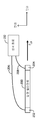
[0004] 도 2는 헤드가 매체 위에 도시되는 헤드-매체 인터페이스의 개략적 예시이다.
[0005] 도 3은 마찰력과 헤드-매체 간격 사이의 관계를 도식적으로 예시한다.
[0006] 도 4는 마찰력을 측정하는 센서 디바이스와 헤드의 일 실시예를 개략적으로 예시한다.
[0007] 도 5는 마찰력을 측정하기 위한 로드 빔 상에 센서 디바이스의 일 실시예를 개략적으로 예시한다.
[0008] 도 6a-6b는 로드 빔에 커플링되는 센서 디바이스를 포함하는 헤드 서스펜션 어셈블리의 일 실시예를 예시한다.
[0009] 도 7a-7b는 로드 빔의 근접 부분과 말단 부분 사이에 커플링되는 센서 디바이스를 포함하는 헤드 서스펜션 어셈블리의 다른 실시예를 예시한다.
[0010] 도 8a-8b는 마찰력을 측정하기 위해 면내 힘 또는 스트레인을 검출하기 위한 센서 디바이스의 실시예들을 예시한다.
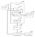
[0011] 도 9는 헤드-매체 인터페이스에서 마찰력의 측정을 출력하기 위해 면내 힘을 검출하기 위한 센서 디바이스 및 헤드의 로컬화된 부분을 돌출시키기 위한 히터 엘리먼트 또는 구동기를 갖는 헤드를 예시한다.
[0012] 도 10a는 매체를 향해 헤드를 돌출시키기 위해 구동기 또는 히터를 에너자이징하기(energize) 위해 파워 온/오프 주파수를 갖는 파워 입력을 예시하며 도 10b는 구동기 또는 히터의 파워 온/오프 주파수에 대응하는 센서 디바이스로부터의 출력을 예시한다.
[0013] 도 10c는 마찰력의 측정치를 출력하기 위해 센서 디바이스에 커플링되는 센서 회로의 일 실시예를 개략적으로 예시한다.
[0014] 도 11a-11b는 마찰력을 측정하고 마찰력의 측정을 활용하여 통과/실패 결정을 출력하도록 구성되는 측정 컴포넌트의 일 실시예를 예시한다.
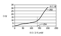
[0015] 도 12a-12b는 헤드 A 및 헤드 B 각각에 대한 마찰력과 히터 전력 사이의 관계를 도식적으로 예시한다.
[0016] 도 13a-13b는 구동기 또는 히터 엘리먼트의 동작을 제어하기 위해 헤드-매체 간격 제어 파라미터들을 출력하고 마찰력을 측정하기 위해 측정 프로세스 또는 절차를 구현하도록 구성되는 측정 컴포넌트의 일 실시예를 예시한다.[0003] Figure 1 is a schematic illustration of a data storage device including a head and a data storage medium for reading data from and / or writing data to a data storage medium.
[0004] FIG. 2 is a schematic illustration of a head-media interface in which the head is shown on the medium.
[0005] FIG. 3 diagrammatically illustrates the relationship between frictional forces and head-to-media spacing.
[0006] FIG. 4 schematically illustrates one embodiment of a sensor device and a head for measuring frictional forces.
[0007] Figure 5 schematically illustrates one embodiment of a sensor device on a load beam for measuring frictional forces.
[0008] Figures 6A-6B illustrate an embodiment of a head suspension assembly including a sensor device coupled to a load beam.
[0009] Figures 7a-7b illustrate another embodiment of a head suspension assembly including a sensor device coupled between a proximal portion and a distal portion of a load beam.
[0010] Figures 8A-8B illustrate embodiments of a sensor device for detecting in-plane forces or strains to measure frictional forces.
[0011] FIG. 9 illustrates a head having a sensor element for detecting an in-plane force and a heater element or actuator for projecting a localized portion of the head to output a measurement of frictional forces at the head-media interface.
[0012] FIG. 10A illustrates a power input with a power on / off frequency to energize a driver or heater to project a head toward the medium; FIG. 10B illustrates a power input on / off frequency of a driver or heater; The output from the sensor device is shown.
[0013] FIG. 10c schematically illustrates one embodiment of a sensor circuit coupled to a sensor device for outputting a measure of frictional force.
[0014] Figures 11A-11B illustrate an embodiment of a measurement component configured to measure frictional forces and utilize measurements of frictional forces to output pass / fail determinations.
[0015] Figures 12A-12B diagrammatically illustrate the relationship between friction force and heater power for head A and head B, respectively.
[0016] Figures 13A-13B illustrate one embodiment of a measurement component configured to implement a measurement process or procedure to output head-to-media spacing control parameters and to measure frictional forces to control operation of a driver or heater element .
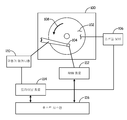
[0017] 본 출원은 도 1에 예시되는 타입의 데이터 스토리지 디바이스를 위한 애플리케이션을 갖는 헤드-매체 인터페이스에서 마찰력을 측정하기 위한 측정 장치 또는 어셈블리에 관한 것이다. 도 1에 도시되는 데이터 스토리지 디바이스(100)는 디지털로 인코딩된 데이터를 저장하는 데이터 스토리지 매체(102)를 포함한다. 헤드(104)는 데이터 스토리지 매체(102)로부터 데이터를 판독하고 및/또는 데이터 스토리지 매체(102)에 데이터를 기록하기 위해 매체(102) 위에 위치설정된다. 도시된 실시예에서, 데이터 스토리지 매체(102)는 회전 디스크이다. 판독 및 기록 동작들을 위해, (개략적으로 예시되는) 스핀들 모터(106)는 화살표(108)에 의해 예시된 바와 같이 매체(102)를 회전시키며 구동기 메커니즘(110)은 매체(102) 상의 데이터 트랙들에 대해 헤드(104)를 위치설정한다. 헤드(104)는 하나 또는 그 초과의 R/W 변환기 엘리먼트들(도 1에 도시되지 않음)을 포함한다. 하나 또는 그 초과의 R/W 변환기 엘리먼트들은 데이터 스토리지 매체(102) 상의 데이터를 인코딩하고 데이터 스토리지 매체(102)로부터 데이터를 디코딩하기 위해 R/W 회로(112)에 전기적으로 커플링된다. 도시된 바와 같이, 스핀들 모터(106) 및 구동기 메커니즘(110)은 구동 회로(114)를 통해 동작된다. 디바이스(100)의 구동 회로(114) 및 R/W 회로(112)는 데이터 스토리지 디바이스(100)의 동작을 위해 호스트 시스템(도시되지 않음)에 커플링된다.[0017] The present application relates to a measuring device or assembly for measuring the friction force in a head-media interface having an application for a data storage device of the type illustrated in FIG. The
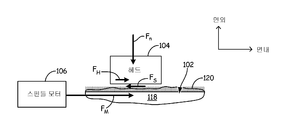
[0018] 도시된 바와 같이, 도 2에서, 헤드(104)는 매체(102)로부터 데이터를 판독하고 및/또는 매체(102)에 데이터를 기록하기 위해 매체(102)와 인터페이싱한다. 매체(102)는 자기적으로 인코딩된 데이터를 저장하기 위한 자기 층(118)을 포함한다. 매체(102)는 비트 패턴화된 매체를 형성하기 위해 비트 패턴을 포함할 수 있다. 데이터는 당업자에 의해 인식된 바와 같은 수직 또는 병렬 레코딩 기술들을 이용하여 매체 상에 저장될 수 있다. 도시된 바와 같이, 박막 윤활층(120)이 매체(102)의 외측 표면 상에 형성된다. 동작을 위해, 매체(102)를 회전시키기 위해 힘(FM)이 스핀들 모터(106)를 통해 가해진다. 도시된 바와 같이, 회전 이전에, 윤활층(120)이 헤드(104)와 매체(102) 사이의 접착 또는 정지마찰력을 제공하도록 헤드(104)는 수직력(Fn)을 통해 박막 윤활층(120)을 향해 바이어스된다. 헤드(104)와 매체(102) 사이의 접착은 매체(102)를 회전시키기 위해 극복되어야 하는 정지 마찰력(fs)을 전달한다. 정지 마찰력(fs)은 헤드(104)와 매체(102) 사이의 정지 마찰 계수 μ 및 헤드의 바이어스력 Fn에 관련되며, fs = μFn이다. 수식 1에 의해 예시된 바와 같이, 매체의 회전은 인가력 FM 마이너스 마찰력 fs와 비례한다.As shown, in FIG. 2, a
FM - fs = m d θ2/dt2 수식 1F M - f s = md? 2 / dt 2 Equation 1
[0019] 도 2에 도시된 바와 같이, 다운-트랙 견인력(FH)은 헤드(104)와 이동 매체 사이의 마찰 또는 정지마찰을 통한 FM을 통해 부분적으로 헤드(104)에 전달된다. 다운-트랙 힘(FH)은 매체에 대해 면내 방향에 있으며 Fn은 면외 방향으로 FH에 수직한다. 헤드에 전달되는 힘(FH)은 헤드와 매체 사이의 마찰의 크기에 비례하며 따라서, 헤드에 전달되는 FH의 측정은 헤드(104)와 매체(102) 사이의 정지 및 동마찰력의 측정을 제공한다. 헤드-매체 간격이 도 3에 도식적으로 예시되는 바와 같이 증가함에 따라 정지 및 동마찰력의 크기는 감소한다.[0019] As shown in FIG. 2, the down-track traction force F H is partially transmitted to the
[0020] 도 4는 본 출원의 측정 어셈블리의 일 실시예를 예시한다. 도 4에 도시된 바와 같이, 어셈블리는 헤드(102)와 매체(104) 사이의 FH 또는 마찰력(134)의 측정을 제공하도록 구성되는 센서 디바이스(130) 및 센서 회로(132)를 포함한다. 센서 디바이스(130)는 센서 디바이스(130)에 전달되는 스트레인 또는 힘에 비례하는 출력 전압 또는 신호를 생성하는 압전기 또는 다른 변환기 엘리먼트를 포함한다. 센서 디바이스(130)는 다운-트랙 방향으로의 축의 힘(FH) 또는 스트레인이 힘(FH)에 비례하는 출력 전압을 생성하기 위해 센서 디바이스(130)에 전달되도록 헤드에 커플링된다. 센서 디바이스(130)로부터의 출력 전압 또는 신호는 센서 디바이스(130)에 전달되는 면내 방향으로 힘 또는 스트레인의 크기에 기초하여 마찰력(134)의 측정을 결정하기 위해 센서 회로(132)에 의해 프로세싱된다.[0020] FIG. 4 illustrates one embodiment of a measurement assembly of the present application. As shown in FIG. 4, the assembly includes a
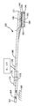
[0021] 도 5는 마찰력을 측정하기 위한 센서 디바이스(130)를 포함하는 헤드(104)에 대한 헤드 서스펜션 어셈블리(138)의 일 실시예를 예시한다. 헤드 서스펜션 어셈블리는 로드 빔(140)을 포함한다. 도시된 바와 같이, 헤드(104)는 짐발(gimbal) 스프링(142)을 통해 로드 빔(140)에 커플링된다. 개략적으로 도시된 바와 같이, 헤드(104)는 슬라이더(144) 상에 제조되는 (개략적으로 예시되는) 하나 또는 그 초과의 R/W 변환기 엘리먼트들(146)을 갖는 슬라이더(144)를 포함한다. 예시적인 R/W 변환기 엘리먼트들(146)은 기술분야에 알려진 바와 같은 유도성 기록 엘리먼트들 및 자기-저항 판독 엘리먼트들 또는 다른 R/W 변환기 엘리먼트를 포함한다. 로드 빔(140)은 슬라이더(144)가 요동하는(pitches and rolls) 짐발 지점을 정의하는 부하 지점 또는 딤플(dimple)(148)을 통해 부하력(Fn)을 슬라이더(144)에 가한다. 동작을 위해 이전에 설명된 바와 같이, 힘(FM)은 (도 1에 도시되는) 방향(108)으로 매체를 회전시키기 위해 스핀들 모터(106)에 의해 공급된다. 방향(108)으로의 매체의 회전은 슬라이더(144)의 리딩 에지(leading edge)(152)로부터 트레일링 에지(trailing edge)(154)로 슬라이더(144)의 공기 베어링 표면(150)을 따라 공기 흐름을 유발시킨다. 슬라이더(144)의 공기 베어링 표면(150)을 따른 공기 흐름은 매체(102)로부터 떨어진 면외 방향으로 상방 양력(lifting force)(F1)을 제공하기 위해 압력 프로파일을 생성한다. 상방력(F1)은 매체(102)를 향해 하향 방향으로 힘(Fn)에 의해 반작용된다. 상방력과 하방력들(F1 및 Fn)의 균형은 판독 및/또는 기록 동작들을 위한 매체 또는 디스크(102) 위의 헤드의 플라이 높이를 정의한다.[0021] FIG. 5 illustrates one embodiment of a
[0022] 도 5에 도시된 바와 같이, 로드 빔(140)은 구동기 블록(162)을 통해 데이터 스토리지 디바이스의 프레임 또는 데크(160)(개략적으로 도시됨)에 회전가능하게 커플링된다. 구동기 블록(162)은 (개략적으로 예시되는) 베어링 어셈블리(164)를 통해 베이스 또는 데크(160)에 회전가능하게 커플링된다. 구동기 메커니즘(110)은 스토리지 매체(102) 상의 선택된 데이터 트랙들에 대해 로드 빔(140)을 통해 헤드를 이동시키기 위해 구동기 블록(162)을 회전시킨다. 도 5에 예시되는 실시예에서, 어셈블리는 헤드-매체 인터페이스에서 헤드에 전달되는 힘(FH)을 측정하기 위해 로드 빔(140) 상의 센서 디바이스(130)를 포함한다. FH는 짐발 지점(148)을 통해 로드 빔(140)에 힘 및/또는 모멘트(FLB 또는 MLB)를 전달한다. 도시된 바와 같이, 센서 디바이스(130)에 전달되는 힘 또는 스트레인은 힘의 적용 지점으로부터 센서 디바이스(130)의 거리로 인해 증가되도록 짐발 지점(148)으로부터 이격되는 거리에서 로드 빔(140)에 커플링된다. 센서 디바이스(130)는 이전에 설명된 바와 같은 헤드-매체 인터페이스에서 마찰력(134)의 측정을 제공하기 위해 센서 디바이스(130)로부터의 출력 전압을 프로세싱하도록 센서 회로(132)에 커플링된다.[0022] As shown in FIG. 5, the
[0023] 도 6a-6b는 이전에 설명된 바와 같은 정지 및 동마찰력을 측정하기 위한 센서 디바이스(130)를 포함하는 헤드 서스펜션 어셈블리(138)의 일 실시예를 예시한다. 도시된 바와 같이, 로드 빔(140)은 로드 빔(140)의 근접 단부(170)와 말단부(172) 사이로 연장하는 늘어난 길이를 갖는다. 로드 빔(140)의 근접단(170)은 스웨이지 플레이트(174)를 통해 구동기 블록(162)에 스웨이징되며 헤드(104)는 이전에 설명된 바와 같은 짐발 스프링(142)을 통해 로드 빔(140)의 말단부(172)에 커플링된다. 기술분야에 알려진 바와 같이 재료 변형을 통해 회전하는 구동기 몸체(162)에 스웨이지 플레이트(174)를 연결하기 위해 (도시되지 않는) 스웨이징 툴이 이용된다. 스웨이징 툴은 구동기 블록(162)에 로드 빔(140)을 연결하기 위해 구동기 블록(162) 및 스웨이지 플레이트(174)의 개구들(176, 178)(도 6b에 도시됨)을 통해 삽입된다. 도시된 실시예에서, 어셈블리의 정지 또는 고정된 부분(160)과 로드 빔 사이의 부하 경로에서 로드 빔(140)의 근접 단(170)과 스웨이지 플레이트(174) 사이에 센서 디바이스(130)가 배치된다. 이전에 설명된 바와 같이, 헤드(104)로부터의 힘(FH)은 로드 빔(140) 및 스트레인들에 전달되거나 헤드-매체 인터페이스에서의 마찰력에 비례하여 센서 디바이스(130)에 축 힘을 전달한다. 센서 회로(132)는 헤드-매체 인터페이스에서 마찰력의 측정을 제공하기 위해 센서 디바이스(130)로부터의 출력을 수신한다.[0023] Figures 6A-6B illustrate an embodiment of a
[0024] 도 7a-7b는 도 6a-6b에 이전에 예시된 바와 같은 헤드(104) 및 짐발 스프링(142)으로부터 이격되는 로드 빔(140)의 길이를 따라 배치되는 센서 디바이스(130)를 포함하는 측정 장치의 다른 실시예를 예시한다. 도 7a-7b에 도시된 바와 같이, 센서 디바이스(130)는 로드 빔(140)의 근접 및 말단부들 사이에 위치되며 로드 빔의 말단 세그먼트(182)로부터 로드 빔(140)의 근접 세그먼트(180)를 분리시킨다. 근접 세그먼트(180)는 스웨이지 플레이트(174)로부터 센서 디바이스(130)의 근접 단(184)으로 연장하며 로드 빔(140)의 말단 세그먼트(182)는 센서 디바이스(130)의 말단(186)으로부터 로드 빔(140)의 말단(172)으로 연장한다. 따라서, 예시된 실시예에서, 센서 디바이스(130)는 헤드 어셈블리의 짐발 지점(148)으로부터 이격되는 로드 빔을 따라 위치된다. 이전에 설명된 바와 같이, 센서 디바이스(130)는 정지 및 동마찰력을 측정하기 위한 힘 또는 스트레인에 응답하여 전압 신호 또는 입력을 제공하는 변환기 엘리먼트를 포함한다.[0024] Figures 7a-7b illustrate a
[0025] 이전의 도면들에 예시되는 센서 디바이스(130)는 입력힘 또는 스트레인에 비례하는 출력 전압 또는 신호를 제공하기 위해 서로 다른 변환기 엘리먼트들을 이용할 수 있다. 도 8a-8b는 입력힘 또는 스트레인에 응답하여 전기적 출력을 제공하기 위해 서로 다른 변환기 엘리먼트들을 활용하는 교번하는 센서 디바이스들을 예시한다. 도 8a에 도시되는 실시예에서, 센서 디바이스(130)는 압전기 엘리먼트 또는 재료(200)를 포함한다. 도시된 바와 같이, 압전기 엘리먼트(200)는 축방향으로 이격된 전극들(202, 204) 사이의 면내 축을 따라 연장하는 길이를 갖는다. 전극들(202, 204) 사이로 연장하는 변환기 엘리먼트(200)의 길이는 면내 축을 따른 힘 또는 스트레인을 검출하기 위해 면내 축을 따라 공동연장하는 센싱 축을 형성한다. 도시된 바와 같이, 전극들(202, 204)은 면내 축을 따른 힘 또는 스트레인에 응답하여 입력 전압 신호를 제공하기 위해 리드들(186, 188)을 통해 센서 회로(132)에 전기적으로 연결된다. 도시되는 압전 변환기 엘리먼트(200)는 측정을 위한 바이어스 전압 또는 전류를 요구하지 않는 수동 센싱 엘리먼트를 제공한다.[0025] The
[0026] 도 7b에 예시되는 다른 실시예에서, 센서 디바이스(130)는 (도식적으로 도시되는) 저항 변환기 엘리먼트(210)를 사용한다. 센서 회로(132)는 저항 엘리먼트(210)를 걸친 저항에서의 변화를 검출하기 위해 접촉 패드들(212, 214)에 연결된다. 저항 엘리먼트(210)는 이전에 설명된 바와 같은 면내 방향으로의 스트레인 또는 힘을 검출하기 위해 센싱 축을 제공하도록 배향되는 늘어난 길이를 갖는다. 도시된 바와 같이, 바이어스 전류 또는 전압(216)은 저항 엘리먼트(210)를 걸쳐 인가되며 접촉 패드들(212, 214)에 걸친 저항은 리드들(218, 219)을 통해 접촉 패드들(212, 214)에 연결되는 센서 회로(132)를 통해 측정된다. 측정된 저항 또는 스트레인은 이전에 설명된 바와 같은 마찰력(134)의 측정을 출력하기 위해 센서 회로(312)에 의해 이용된다.[0026] In another embodiment, illustrated in FIG. 7B, the
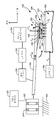
[0027] 도 9에 도시된 바와 같이, 헤드(104)는 R/W 회로(112)에 연결되는 하나 또는 그 초과의 변환기 엘리먼트들(146) 및 슬라이더의 트레일링 에지에 근접한 구동기 엘리먼트(220)를 포함한다. 구동기 엘리먼트(220)는 제어기(222)의 제어 하에서 매체를 향해 헤드 및 변환기 엘리먼트들(146)의 로컬화된 부분을 돌출시키기 위해 에너자이징된다. 예시된 실시예에서, 구동기 엘리먼트(220)는 헤드(104)의 로컬화된 부분을 돌출시키기 위해 제어기(222)에 의해 동작되거나 파워링되는 저항 히터(heater) 엘리먼트이다. 도시된 바와 같이 어셈블리는 마찰력을 측정하는 측정 알고리즘들 또는 절차들을 구현하기 위한 측정 컴포넌트(224)를 포함한다. 측정 컴포넌트(224)는 헤드(104)의 로컬화된 부분을 돌출시키기 위해 구동기 또는 히터(220)를 동작시키도록 구동기 제어 파라미터들(225)을 제공한다. 측정 컴포넌트(224)는 메모리에 저장되며 및/또는 데이터 스토리지 디바이스에 의해 이용되는 마찰력의 출력 측정을 제공하기 위해 센서 회로(132)로부터의 출력을 활용한다. 측정 컴포넌트(224)에 의해 구현되는 알고리즘 또는 절차는 FLASH, EPROM과 같은 비-휘발성 메모리를 포함하는 메모리에 저장되는 명령들을 이용하여 또는 디지털 또는 아날로그 회로 컴포넌트들을 통해 구현될 수 있다. 저항 히팅 엘리먼트가 도시되더라도, 애플리케이션은 히팅 엘리먼트에 제한되지 않으며 압전 구동기 엘리먼트와 같은 다른 구동기 엘리먼트들이 본원에 설명된 바와 같은 헤드의 로컬화된 부분을 돌출시키기 위해 사용될 수 있다.9, the
[0028] 도 10a는 구동기 또는 히터(220)를 동작시키기 위한 파워 입력(226) 및 도 10b에 도시된 바와 같은 센서 디바이스(130)의 대응하는 변형 또는 여기(227)를 예시한다. 도 10a에 도시된 바와 같이, 파워 입력(226)은 시간에 관한 파워 온/오프 사이클 또는 주파수(228)를 포함한다. 파워는 최대 전력 진폭까지 "온"으로 사이클링되며 거의 제로까지 "오프"로 사이클링된다. 도 10a-10b에 협력가능하게 예시되는 바와 같이, 접촉 이전의 낮은 전력 레벨들(파워 < 100mW)에서, 센서 출력(227) 또는 마찰력은 제로 또는 거의 제로이다. 전력이 (100mW 위로) 증가하며 헤드가 매체(104)를 거의 접촉하거나 접촉함에 따라, 정지 및 동마찰 및 센서 출력(227)의 측정은 도시된 바와 같이 증가한다.[0028] FIG. 10a illustrates a corresponding deformation or
[0029] 도 10c에 도시된 바와 같이, 파워 온/오프 주파수(228)는 헤드-매체 인터페이스에서의 마찰력 또는 FH에 대응하는 센서 디바이스(130)의 여기를 추출하기 위해 이용되는 기준 주파수를 제공한다. 특히, 마찰력의 결과로서 센서 디바이스(130)의 여기 주파수는 파워 온/오프 주파수(228)에 대응하며 따라서 마찰력으로부터 발생하는 센서 디바이스(130)로부터의 출력은 파워 온/오프 주파수(228)를 이용하여 잡음 또는 다른 여기 또는 힘들로부터 격리될 수 있다. 구동기 엘리먼트 또는 히터(220)의 온/오프 사이클 또는 주파수(228)는 또한 신호 드리프트(drift)를 감소시킨다. 마찰 모드에 대응하는 센서 디바이스(130)의 여기 주파수가 헤드 및 서스펜션 어셈블리의 진동 모드들의 주파수 및 다른 고주파수 잡음보다 낮도록 낮은 파워 온/오프 주파수(228)가 이용된다.As shown in FIG. 10C, the power on / off
[0030] 도 10c는 출력 마찰 측정(134)을 제공하기 위해 출력 센서 신호(227)를 프로세싱하는 센서 회로(132)의 일 실시예를 예시한다. 도 10c에 도시된 바와 같이, 센서 회로(132)는 출력 센서 신호(227) 및 파워 기준 신호 또는 주파수(228)를 수신하며 센서 출력(227)으로부터 마찰력 성분을 추출하기 위해 기준 주파수(228)를 이용하는 검출기 컴포넌트(230)를 포함한다. 예시된 실시예에서, 검출기 컴포넌트(230)는 출력 신호(227)로부터 마찰 성분을 추출하기 위해 기준 신호를 이용하는 로크 인(lock in) 증폭기 검출기이다. 파워 온/오프 주파수(228)는 주파수가 구동기 또는 히터 시간 제약들과 관련되는 주파수보다 낮아서 구동기 또는 히터(220)가 구동기 또는 히터 "온" 기간 동안 완전히 구동된 상태에 도달할 수 있도록 선택된다. 추가로 파워 온/오프 주파수(228)는 정지 또는 동마찰의 측정을 위한 뚜렷한 주파수 응답을 제공하기 위해 스핀들 모터 또는 서스펜션 어셈블리의 공진 모드들과 같은, 디바이스의 컴포넌트들의 공진 주파수들과 다르다.[0030] FIG. 10C illustrates one embodiment of
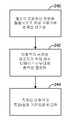
[0031] 도 11a-11b는 디바이스 또는 드라이브(100)를 위한 통과/실패 측정을 결정하는 센서 디바이스(130)의 적용을 예시한다. 도 11a에 도시된 실시예에서, 측정 컴포넌트(224)는 통과/실패 알고리즘(234)을 구현하도록 구성된다. 통과/실패 알고리즘(234)은 센서 디바이스(130)를 이용하여 마찰력을 측정하기 위해 파워 온/오프 주파수(228)에서 헤드(104)의 로컬화된 부분을 돌출시키도록 구동기(220)를 동작시킨다. 도시된 바와 같이, 측정 컴포넌트(224)는 또한 통과/실패 결정기(235)를 포함한다. 센서 디바이스(130)로부터의 출력 또는 측정은 통과/실패 결정기(235)에 제공된다. 통과/실패 결정기(235)는 드라이브 또는 디바이스(100)가 품질 표준들을 충족시키며 출력 통과/실패 측정(236)을 제공하는지 여부를 결정하기 위해 측정된 마찰력을 이용한다. 도 11b에 도시된 바와 같이, 통과/실패 알고리즘(234)은 단계(240)에서 도시된 바와 같이 매체를 향해 슬라이더(144)의 트레일링 에지 부분을 돌출시키기 위해 구동기 또는 히터(220)에 파워를 인가한다. 단계(242)에서, 센서 디바이스(130)로부터의 출력은 마찰력의 측정을 제공하기 위해 프로세싱된다. 도시된 바와 같이, 단계(244)에서, 측정된 마찰력은 통과/실패 측정(236)을 출력하기 위해 통과/실패 기준들과 비교된다. 설명된 바와 같이, 통과/실패 알고리즘(234)은 품질 제어 테스팅을 위해 통과/실패 측정(236)을 출력하기 위해 측정된 마찰력 및 통과/실패 기준들을 이용한다.[0031] Figures 11A-11B illustrate application of a
[0032] 도 12a-12b는 헤드 A 및 헤드 B에 대한 측정된 마찰력(250, 252) 히터 파워를 도식적으로 예시한다. 도 12a에 도시된 바와 같이, 임계값 파워 레벨(254)에서 또는 그를 초과하여, 헤드는 매체(102)를 접촉한다. 따라서, 임계 레벨(254) 미만에서 헤드는 매체 위에 있거나 매체로부터 이격되며 따라서, 마찰력은 제로 또는 거의 제로에 있다. 구동기 엘리먼트(220)에 대한 헤드 매체 접촉 수직 구동 파워를 결정하는 것은 헤드를 신뢰성 있게 동작시키기 위한 올바른 헤드-매체 간격을 설정하기 위해 데이터 스토리지 디바이스에 대해 대단히 중요하다. 도 12b에서 반대로, 헤드 B는 불안정하여 임계 레벨(254) 미만에서 간헐적 헤드-매체 접촉을 표시하는 마찰력의 측정이 존재한다. 도시된 바와 같이, 품질 제어를 위해 결함있는 헤드들 또는 컴포넌트를 검출하기 위해 도 11a에 예시되는 결정기(235)에 의해 센서 디바이스(130)로부터의 출력 마찰력이 이용된다. 도 12a에서의 헤드 A에 대한 측정된 마찰력에 기초하여, 결정기(235)는 통과 측정을 출력할 것이며, 예시된 실시예에서, 제어기 회로(222)는 접촉 임계 파워 레벨(254)에 기초하여 올바른 구동 전력으로 구동기 엘리먼트(220)를 동작시킬 것인 한편, 도 12b에서의 헤드 B를 위해 결정기(235)는 헤드 B에 대한 플라이 높이가 헤드-매체 접촉 임계값(254) 미만의 낮은 파워 레벨들에서 불안정하기 때문에 실패 측정을 출력할 것이다.[0032] Figures 12a-12b diagrammatically illustrate the measured frictional force (250, 252) heater power for head A and head B. [ As shown in FIG. 12A, at or above the
[0033] 도 13a-13b는 마찰력(134)의 출력 측정을 활용하여 능동 헤드-매체 간격 제어를 제공하기 위한 일 실시예를 예시한다. 도시된 바와 같이, 도 13a의 예시된 실시예에서, 측정 컴포넌트(224)는 마찰력을 측정하기 위해 헤드(104)의 로컬화된 부분을 돌출시키도록 구동기 또는 히터(220)를 파워 온/오프하기 위한 알고리즘(260) 및 판독 및 기록 동작들을 위해 원하는 플라이 높이를 제공하기 위해 구동기 또는 히터(220)를 동작시키도록 헤드-매체 간격 제어 파라미터들(264)을 제공하기 위한 능동 제어 컴포넌트(262)를 포함한다. 도 13b에 예시된 바와 같이, 알고리즘(260)은 마찰력을 측정하기 위해 단계(266)에 예시된 바와 같은 파워 온/오프 주파수(228)에서 파워를 인가한다. 단계(267)에서 능동 제어 컴포넌트(262)는 원하는 헤드-매체 간격을 제공하기 위해 적절한 양으로 구동기(220)를 파워링하기 위해 능동 제어 파라미터들(264)을 결정하도록 마찰력의 출력 측정을 이용한다. 단계(268)에서, 제어기는 판독 및 기록 동작들 동안 헤드-매체 간격을 최적화하기 위해 헤드를 돌출시키도록 구동기(220)에 파워를 인가하기 위해 능동 제어 파라미터들(264)을 이용한다.[0033] Figures 13A-13B illustrate an embodiment for providing active head-to-media spacing control utilizing output measurements of
[0034] 측정 어셈블리의 다양한 이용들이 본 출원에 개시되더라도, 실시예들은 본 출원에 개시되는 특정 애플리케이션이나 이용에 제한되지 않는다. 본 발명의 다양한 실시예들의 구조 및 기능의 상세들과 함께, 본 발명의 다양한 실시예들의 수많은 특성들 및 장점들이 전술한 설명에서 설명되었더라도, 본 개시물은 단지 예시적이며, 첨부된 청구범위들이 표현되는 용어들의 넓은 일반적 의미에 의해 표시되는 전체 범위까지 본 발명의 원리들 내의 일부분들의 구조 및 배치의 관점에서 특히, 상세하게 변경들이 이루어질 수 있음이 이해될 것이다. 예를 들어, 특정 엘리먼트들은 본 발명의 범위 및 정신으로부터 이탈하지 않고서 동일한 기능을 실질적으로 유지하면서 시스템에 대한 특정 애플리케이션에 따라 변화할 수 있다. 추가로, 본원에 설명되는 바람직한 실시예가 특정 데이터 스토리지 시스템에 관한 것이더라도, 본 발명의 교시들이 본 발명의 범위 및 정신을 이탈하지 않고서, 광학 디바이스들과 같은 다른 데이터 스토리지 디바이스에 적용될 수 있음이 당업자에 의해 인식될 것이다.[0034] Although various uses of measurement assemblies are disclosed in this application, embodiments are not limited to the specific applications or uses disclosed in this application. While numerous features and advantages of various embodiments of the invention have been set forth in the foregoing description, along with the details of construction and function of various embodiments of the invention, the disclosure is merely illustrative, and the appended claims It will be understood that changes may be made in detail, especially in light of the structure and arrangement of portions within the principles of the invention, to the full extent indicated by the broad general meaning of the terms represented. For example, certain elements may vary depending upon the particular application for the system, while substantially retaining the same functionality without departing from the scope and spirit of the invention. Further, although the preferred embodiments described herein relate to a particular data storage system, it will be appreciated by those skilled in the art that the teachings of the present invention may be applied to other data storage devices, such as optical devices, without departing from the scope and spirit of the invention Lt; / RTI >
Claims (20)
면내(in-plane) 축을 따라 연장하는 늘어난 길이를 갖는 로드 빔;
상기 면내 축에 일반적으로 횡단하는 면외(out-of-plane) 축을 따라 헤드에 부하력을 공급하기 위해 짐발(gimbal) 스프링을 통해 상기 로드 빔에 커플링되는 헤드; 및
상기 면내 축을 따라 변환기 엘리먼트에 전달되는 힘 또는 스트레인(strain)에 응답하여 전기적 출력을 제공하기 위해 상기 로드 빔의 상기 면내 축을 따라 배향되는 센싱 축을 갖는 변환기 엘리먼트를 포함하는 상기 로드 빔에 커플링되는 센서 디바이스를 포함하는, 어셈블리.As an assembly,
A load beam having an elongated length extending along an in-plane axis;
A head coupled to the load beam via a gimbal spring to provide a load force to the head along an out-of-plane axis that is generally transverse to the in-plane axis; And
A transducer element having a sensing axis oriented along the in-plane axis of the load beam to provide an electrical output in response to force or strain transmitted to the transducer element along the in-plane axis; and a transducer element coupled to the load beam, ≪ / RTI >
마찰력의 출력 측정을 제공하기 위해 상기 변환기 엘리먼트에 전달되는 상기 힘 또는 스트레인에 응답하여 상기 전기적 출력을 프로세싱하기 위해 상기 변환기 엘리먼트에 커플링되는 컨택트들을 통해 상기 센서 디바이스에 커플링되는 센서 회로를 포함하는, 어셈블리.The method according to claim 1,
And a sensor circuit coupled to the sensor device via contacts coupled to the transducer element for processing the electrical output in response to the force or strain imparted to the transducer element to provide an output measurement of the frictional force , Assembly.
상기 센서 회로는 상기 센서 디바이스로부터의 상기 전기적 출력으로부터 마찰력의 상기 측정을 추출하기 위해 기준 신호를 활용하도록 구성되는 검출기 컴포넌트를 포함하는, 어셈블리.3. The method of claim 2,
Wherein the sensor circuit comprises a detector component configured to utilize a reference signal to extract the measurement of the frictional force from the electrical output from the sensor device.
상기 검출기 컴포넌트는 로크-인(lock-in) 증폭기 검출기인, 어셈블리.The method of claim 3,
Wherein the detector component is a lock-in amplifier detector.
상기 변환기 엘리먼트는 압전 변환기 엘리먼트이며 상기 압전기 변환기 엘리먼트의 제 1 단에 커플링되는 제 1 전극 및 상기 면내 축을 따라 상기 제 1 전극으로부터 축방향으로 이격되는 상기 압전 변환기 엘리먼트의 제 2 단에 커플링되는 제 2 전극을 포함하는, 어셈블리.The method according to claim 1,
Wherein the transducer element is a piezoelectric transducer element and is coupled to a first end coupled to a first end of the piezoelectric transducer element and to a second end of the piezoelectric transducer element axially spaced from the first electrode along the in- And a second electrode.
상기 제 1 및 제 2 전극들에 커플링되는 리드들을 통해 상기 압전 변환기 엘리먼트에 커플링되며 마찰력의 측정을 출력하기 위해 상기 압전 변환기 엘리먼트로부터의 상기 전기적 출력을 활용하도록 구성되는, 어셈블리.6. The method of claim 5,
And is configured to utilize the electrical output from the piezoelectric transducer element to output a measurement of the frictional force coupled to the piezoelectric transducer element through leads coupled to the first and second electrodes.
상기 센서 디바이스는 스트레인 게이지(strain gauge)이며 상기 변환기 엘리먼트는 상기 면내 축을 따라 배향되는 늘어난 길이를 갖는 저항 엘리먼트 및 상기 저항 엘리먼트의 이격된 단들에 커플링되는 접촉 패드들을 포함하는, 어셈블리.The method according to claim 1,
Wherein the sensor device is a strain gauge and the transducer element comprises a resistive element having an elongated length oriented along the in-plane axis and contact pads coupled to spaced apart steps of the resistive element.
상기 접촉 패드들에 커플링되는 리드들을 통해 상기 저항 엘리먼트에 커플링되는 센서 회로를 포함하는, 어셈블리.8. The method of claim 7,
And a sensor circuit coupled to the resistive element through leads coupled to the contact pads.
상기 센서 디바이스는 구동기 블록에 상기 로드 빔을 연결하는 스웨이지 플레이트(swage plate)와 상기 헤드로부터 이격된 상기 로드 빔의 근접 단 사이에 상기 로드 빔에 커플링되는, 어셈블리.The method according to claim 1,
Wherein the sensor device is coupled to the load beam between a swage plate connecting the load beam to a driver block and a proximal end of the load beam spaced from the head.
상기 로드 빔은 구동기 블록에 커플링되는 근접 부분 및 상기 짐발 스프링을 통해 상기 헤드에 커플링되는 말단 부분을 포함하며, 상기 센서 디바이스는 상기 로드 빔의 상기 근접 및 말단 부분들 사이의 상기 로드 빔에 연결되는, 어셈블리.The method according to claim 1,
Wherein the load beam includes a proximal portion coupled to the driver block and a distal portion coupled to the head via the gimbals spring, the sensor device having a proximal portion coupled to the load beam between the proximal and distal portions of the load beam Connected, assembly.
하나 또는 그 초과의 변환기 엘리먼트들을 포함하는 헤드;
매체를 향해 상기 헤드의 상기 하나 또는 그 초과의 변환기 엘리먼트들을 구동하기 위해 상기 헤드에 커플링되는 구동기 엘리먼트;
상기 헤드에 전달되는 마찰력에 응답하여 전압 신호를 출력하도록 구성되는 센서 디바이스;
상기 매체를 향해 상기 하나 또는 그 초과의 변환기 엘리먼트들을 주기적으로 구동시키기 위해 파워 온/오프 주파수에서 상기 구동기 엘리먼트를 파워 온 및 파워 오프하도록 구성되는 측정 컴포넌트;
상기 센서 디바이스에 커플링되며 상기 마찰력의 측정을 제공하기 위해 상기 센서 디바이스로부터의 상기 출력을 프로세싱하기 위해 상기 파워 온/오프 주파수를 활용하도록 구성되는 센서 회로를 포함하는, 어셈블리.As an assembly,
A head comprising one or more transducer elements;
A driver element coupled to the head for driving the one or more transducer elements of the head toward the medium;
A sensor device configured to output a voltage signal in response to a frictional force transmitted to the head;
A measuring component configured to power on and power off the driver element at a power on / off frequency to periodically drive the one or more transducer elements toward the medium;
And a sensor circuit coupled to the sensor device and configured to utilize the power on / off frequency to process the output from the sensor device to provide a measurement of the frictional force.
상기 헤드는 로드 빔 및 짐발 스프링을 포함하는 서스펜션 어셈블리에 커플링되며 상기 헤드는 상기 짐발 스프링을 통해 상기 로드 빔에 커플링되며 상기 센서 디바이스는 상기 헤드에 전달되는 마찰력에 응답하여 상기 출력 전압 신호를 제공하기 위해 상기 로드 빔 상에 있는, 어셈블리.12. The method of claim 11,
Wherein the head is coupled to a suspension assembly comprising a load beam and a gimbal spring, the head coupled to the load beam via the gimbal spring and the sensor device responsive to a frictional force transmitted to the head to transmit the output voltage signal Wherein the load beam is on the load beam for providing.
상기 구동기 엘리먼트는 히터이며 상기 헤드를 향해 상기 하나 또는 그 초과의 변환기 엘리먼트들을 구동하기 위해 상기 히터에 파워를 주기적으로 인가하도록 상기 파워 온/오프 주파수를 활용하는 제어기를 통해 상기 히터가 제어되는, 어셈블리.12. The method of claim 11,
Wherein the actuator element is a heater and the heater is controlled through a controller utilizing the power on / off frequency to periodically apply power to the heater to drive the one or more transducer elements toward the head, .
상기 센서 회로는 상기 헤드에 전달되는 마찰력으로부터 발생하는 상기 센서 디바이스의 여기를 검출하기 위해 상기 파워 온/오프 주파수를 이용하는 검출기 컴포넌트를 포함하는, 어셈블리.12. The method of claim 11,
Wherein the sensor circuit comprises a detector component that utilizes the power on / off frequency to detect an excitation of the sensor device resulting from a frictional force transmitted to the head.
상기 센서 디바이스는 상기 로드 빔의 면내 축을 따라 이격되는 제 1 및 제 2 전극들 사이로 연장하는 늘어난 길이를 갖는 압전 변환기 엘리먼트를 포함하며 상기 로드 빔은 면외(out-of-plane) 축을 따라 상기 헤드에 부하력을 인가하도록 구성되는, 어셈블리.13. The method of claim 12,
The sensor device includes a piezoelectric transducer element having an elongated length extending between first and second electrodes spaced along an in-plane axis of the load beam, the load beam having an out-of- An assembly configured to apply a load force.
상기 센서 디바이스는 면외 축에 일반적으로 횡단하는 면내 축을 따라 스트레인을 검출하기 위해 상기 로드 빔의 면내 축을 따라 연장하는 길이를 갖는 저항 변환기 엘리먼트를 포함하는 스트레인 게이지(gauge)를 포함하는, 어셈블리.13. The method of claim 12,
Wherein the sensor device comprises a strain gauge comprising a resistive transducer element having a length extending along an in-plane axis of the load beam for detecting strain along an in-plane axis generally transverse to the out-of-plane axis.
매체를 향해 헤드를 돌출시키기 위해 구동기에 파워를 인가하는 단계;
상기 헤드에 전달되는 마찰력에 응답하여 센서 디바이스로부터 입력을 수신하는 단계; 및
마찰력의 측정을 출력하기 위해 상기 센서 디바이스로부터 상기 입력을 프로세싱하는 단계를 포함하는, 방법.As a method,
Applying power to the actuator to project the head towards the medium;
Receiving an input from a sensor device in response to a frictional force transmitted to the head; And
And processing the input from the sensor device to output a measurement of the frictional force.
상기 매체를 향해 상기 헤드를 간헐적으로 돌출시키기 위해 파워 온/오프 주파수에서 상기 구동기를 주기적으로 파워링 온 및 오프하는 단계; 및
상기 마찰력의 측정을 출력하기 위해 상기 마찰력에 응답하여 상기 센서 디바이스의 여기를 검출하기 위해 상기 파워 온/오프 주파수를 활용하는 단계를 포함하는, 방법.18. The method of claim 17, wherein applying power comprises:
Periodically powering on and off the driver at a power on / off frequency to intermittently protrude the head toward the medium; And
And utilizing the power on / off frequency to detect an excitation of the sensor device in response to the frictional force to output a measurement of the frictional force.
통과/실패 측정을 출력하기 위해 상기 측정된 마찰력 대 상기 구동기에 인가된 파워를 이용하는 단계를 포함하는, 방법.18. The method of claim 17,
Using the measured frictional force versus power applied to the driver to output a pass / fail measurement.
판독 또는 기록 동작들을 위한 헤드-매체 간격을 제어하기 위해 상기 구동기에 상기 파워를 인가하도록 헤드-매체 간격 제어 파라미터들을 발생시키기 위해 상기 측정된 마찰력을 이용하는 단계를 포함하는, 방법.18. The method of claim 17,
Using the measured frictional force to generate head-to-media interval control parameters to apply the power to the actuator to control head-to-media spacing for read or write operations.
Applications Claiming Priority (2)
| Application Number | Priority Date | Filing Date | Title |
|---|---|---|---|
| US13/790,820 | 2013-03-08 | ||
| US13/790,820 US9171581B2 (en) | 2013-03-08 | 2013-03-08 | Friction force measurement assembly and method |
Publications (1)
| Publication Number | Publication Date |
|---|---|
| KR20140110764A true KR20140110764A (en) | 2014-09-17 |
Family
ID=51465325
Family Applications (1)
| Application Number | Title | Priority Date | Filing Date |
|---|---|---|---|
| KR1020140026383A KR20140110764A (en) | 2013-03-08 | 2014-03-06 | Friction force measurement assembly and method |
Country Status (4)
| Country | Link |
|---|---|
| US (1) | US9171581B2 (en) |
| JP (1) | JP6043308B2 (en) |
| KR (1) | KR20140110764A (en) |
| CN (1) | CN104034467A (en) |
Families Citing this family (3)
| Publication number | Priority date | Publication date | Assignee | Title |
|---|---|---|---|---|
| US9595280B2 (en) * | 2015-02-26 | 2017-03-14 | Western Digital Technologies, Inc | Hard disk drive head-disk interface dithering |
| CN105675059B (en) * | 2016-03-01 | 2017-08-25 | 中国科学院合肥物质科学研究院 | A kind of multifunctional bionic micro-structure surface test device |
| US10989649B2 (en) * | 2017-12-13 | 2021-04-27 | Seagate Technology Llc | Methods of measuring friction between a slider and ramp, and related systems |
Family Cites Families (28)
| Publication number | Priority date | Publication date | Assignee | Title |
|---|---|---|---|---|
| JPS6370149A (en) | 1986-09-10 | 1988-03-30 | Kubota Ltd | Apparatus for measuring friction factor between magnetic disc and magnetic head |
| US5235512A (en) | 1991-06-24 | 1993-08-10 | Ford Motor Company | Self-tuning speed control for a vehicle |
| JPH07161023A (en) * | 1993-12-07 | 1995-06-23 | Hitachi Ltd | Magnetic memory device |
| KR960016899B1 (en) * | 1993-12-31 | 1996-12-26 | 삼성전자 주식회사 | Method and device for preventing impact of hdd |
| US5594595A (en) * | 1995-01-19 | 1997-01-14 | Conner Peripherals, Inc. | FM detection of slider-disk interface |
| JP3333079B2 (en) | 1995-12-25 | 2002-10-07 | 富士通株式会社 | Static friction force measuring device |
| US5923487A (en) * | 1997-06-05 | 1999-07-13 | Maxtor Corporation | Integrated shock sensing device |
| JP3999886B2 (en) | 1998-08-21 | 2007-10-31 | 富士通株式会社 | Friction coefficient measuring method and head slider for magnetic disk drive |
| US6196062B1 (en) | 1999-05-20 | 2001-03-06 | Seagate Technology Llc | Trailing edge acoustic emission sensor and pyroelectric sensor for asperity detection |
| US6501625B1 (en) * | 1999-06-29 | 2002-12-31 | Hutchinson Technology Incorporated | Disk drive suspension with multi-layered piezoelectric actuator controlled gram load |
| JP2005004909A (en) * | 2003-06-13 | 2005-01-06 | Hitachi Global Storage Technologies Inc | Magnetic disk device and floating control method of magnetic head slider |
| US7312941B2 (en) | 2003-09-17 | 2007-12-25 | Hitachi Global Storage Technologies Netherlands B.V. | Disk drive with head-disk interaction sensor integrated with suspension |
| US7171845B2 (en) | 2005-02-16 | 2007-02-06 | Hitachi Global Storage Technologies Netherlands B.V. | Apparatus for measurement of friction force at the interface of a slider and rotating disk |
| US8310779B2 (en) | 2005-04-27 | 2012-11-13 | Seagate Technology Llc | Head assembly having a sensing element |
| US7079339B1 (en) * | 2005-06-03 | 2006-07-18 | Hitachi Global Storage Technologies Netherlands B.V. | Dual-stage actuator disk drive with method for secondary-actuator failure detection and recovery using a relative-position sensor while track following |
| JP2007179717A (en) * | 2005-12-01 | 2007-07-12 | Fujitsu Ltd | Contact detection apparatus, contact detection method, and method for manufacturing head |
| US7349170B1 (en) * | 2006-04-28 | 2008-03-25 | Western Digital (Fremont), Llc | Method of monitoring operation of a disk drive by analyzing the envelope of a read-back signal in the frequency domain |
| US9202495B2 (en) | 2007-05-01 | 2015-12-01 | Seagate Technology Llc | Method and apparatus for detecting proximity contact between a transducer and a medium |
| JP4897049B2 (en) | 2007-08-21 | 2012-03-14 | 東芝ストレージデバイス株式会社 | Recording medium driving apparatus and friction characteristic measuring method |
| US7990647B2 (en) * | 2008-07-03 | 2011-08-02 | Hitachi Global Storage Technologies Netherlands B.V. | Thermally assisted recording head control means for protrusion management |
| JP2010040127A (en) * | 2008-08-07 | 2010-02-18 | Hitachi Global Storage Technologies Netherlands Bv | Test head for magnetic disk, and method for manufacturing magnetic disk using the same |
| US20100079908A1 (en) * | 2008-09-29 | 2010-04-01 | Infinitum Solutions, Inc. | Determining A Magnetic Sample Characteristic Using A Magnetic Field From A Domain Wall |
| US7830634B2 (en) * | 2008-12-23 | 2010-11-09 | Hitachi Global Storage Technologies Netherlands, B.V. | Head-disk contact detection and work function difference determination |
| JP2010244642A (en) * | 2009-04-08 | 2010-10-28 | Toshiba Storage Device Corp | Memory device, and method for determining contact of head slider |
| JP2010257532A (en) * | 2009-04-24 | 2010-11-11 | Toshiba Storage Device Corp | Magnetic disk device, frictional force measurement method and magnetic disk control device |
| US8085491B2 (en) * | 2010-02-26 | 2011-12-27 | Tdk Corporation | Method of determining flying height of magnetic head |
| US8199431B2 (en) * | 2010-04-08 | 2012-06-12 | Tdk Corporation | Magnetic head including sensor |
| US8941951B2 (en) * | 2012-11-28 | 2015-01-27 | Hutchinson Technology Incorporated | Head suspension flexure with integrated strain sensor and sputtered traces |
-
2013
- 2013-03-08 US US13/790,820 patent/US9171581B2/en active Active
-
2014
- 2014-03-06 KR KR1020140026383A patent/KR20140110764A/en active Search and Examination
- 2014-03-07 JP JP2014044975A patent/JP6043308B2/en not_active Expired - Fee Related
- 2014-03-07 CN CN201410083200.8A patent/CN104034467A/en active Pending
Also Published As
| Publication number | Publication date |
|---|---|
| JP6043308B2 (en) | 2016-12-14 |
| US9171581B2 (en) | 2015-10-27 |
| JP2014175042A (en) | 2014-09-22 |
| CN104034467A (en) | 2014-09-10 |
| US20140254341A1 (en) | 2014-09-11 |
Similar Documents
| Publication | Publication Date | Title |
|---|---|---|
| US9390741B2 (en) | Head transducer with multiple resistance temperature sensors for head-medium spacing and contact detection | |
| US9047898B2 (en) | Head-medium contact detection using introduced heat oscillation | |
| US8995076B1 (en) | Head-medium contact detection using electromagnetic attraction | |
| US7411389B1 (en) | Method of detecting changes in operability status of a slider mover in a disk drive | |
| US7564649B2 (en) | Head assembly having a sensing element to provide feedback for head-media instability | |
| US20080239581A1 (en) | Apparatus for determining contact of head slider and method of determining contact of head slider | |
| US9685182B1 (en) | Non-contact laser-induced protrusion measurement apparatus and method | |
| US9093084B2 (en) | Flexible biasing strategy for ground-split TCR sensors | |
| US9607642B1 (en) | Head-medium contact detection using a thermal sensor and surface charge control of a slider | |
| US9437234B1 (en) | Head-medium contact detection using high frequency heater oscillation | |
| US20040085670A1 (en) | Method for measuring pad wear of padded slider with MRE cooling effect | |
| KR100468766B1 (en) | Method for controlling flying height between head and disk and apparatus thereof | |
| US20080192379A1 (en) | Manufacturing method for magnetic disk drive | |
| KR20140110764A (en) | Friction force measurement assembly and method | |
| US9595277B2 (en) | Thermally assisted writer protrusion determination and control | |
| JP6266668B2 (en) | Apparatus and method using simultaneous detection of head-disk contact by modulation and friction heating | |
| JP3999886B2 (en) | Friction coefficient measuring method and head slider for magnetic disk drive | |
| US9721603B2 (en) | Head-medium contact detection using an oscillating electromagnetic force | |
| US8908317B1 (en) | Method for detecting touchdown of head and disk storage apparatus | |
| US9761270B1 (en) | Data storage device using high and low frequencies AC heat produce position-error-signals for head contact detection |
Legal Events
| Date | Code | Title | Description |
|---|---|---|---|
| A201 | Request for examination | ||
| AMND | Amendment | ||
| E902 | Notification of reason for refusal | ||
| AMND | Amendment | ||
| E601 | Decision to refuse application | ||
| AMND | Amendment |