KR20140102014A - Laundry Treating Apparatus - Google Patents
Laundry Treating Apparatus Download PDFInfo
- Publication number
- KR20140102014A KR20140102014A KR1020130015375A KR20130015375A KR20140102014A KR 20140102014 A KR20140102014 A KR 20140102014A KR 1020130015375 A KR1020130015375 A KR 1020130015375A KR 20130015375 A KR20130015375 A KR 20130015375A KR 20140102014 A KR20140102014 A KR 20140102014A
- Authority
- KR
- South Korea
- Prior art keywords
- drum
- liquid
- flow path
- balancer
- space
- Prior art date
Links
Images


Classifications
-
- D—TEXTILES; PAPER
- D06—TREATMENT OF TEXTILES OR THE LIKE; LAUNDERING; FLEXIBLE MATERIALS NOT OTHERWISE PROVIDED FOR
- D06F—LAUNDERING, DRYING, IRONING, PRESSING OR FOLDING TEXTILE ARTICLES
- D06F33/00—Control of operations performed in washing machines or washer-dryers
- D06F33/30—Control of washing machines characterised by the purpose or target of the control
- D06F33/48—Preventing or reducing imbalance or noise
-
- F—MECHANICAL ENGINEERING; LIGHTING; HEATING; WEAPONS; BLASTING
- F16—ENGINEERING ELEMENTS AND UNITS; GENERAL MEASURES FOR PRODUCING AND MAINTAINING EFFECTIVE FUNCTIONING OF MACHINES OR INSTALLATIONS; THERMAL INSULATION IN GENERAL
- F16F—SPRINGS; SHOCK-ABSORBERS; MEANS FOR DAMPING VIBRATION
- F16F15/00—Suppression of vibrations in systems; Means or arrangements for avoiding or reducing out-of-balance forces, e.g. due to motion
- F16F15/32—Correcting- or balancing-weights or equivalent means for balancing rotating bodies, e.g. vehicle wheels
-
- D—TEXTILES; PAPER
- D06—TREATMENT OF TEXTILES OR THE LIKE; LAUNDERING; FLEXIBLE MATERIALS NOT OTHERWISE PROVIDED FOR
- D06F—LAUNDERING, DRYING, IRONING, PRESSING OR FOLDING TEXTILE ARTICLES
- D06F37/00—Details specific to washing machines covered by groups D06F21/00 - D06F25/00
- D06F37/20—Mountings, e.g. resilient mountings, for the rotary receptacle, motor, tub or casing; Preventing or damping vibrations
- D06F37/22—Mountings, e.g. resilient mountings, for the rotary receptacle, motor, tub or casing; Preventing or damping vibrations in machines with a receptacle rotating or oscillating about a horizontal axis
- D06F37/225—Damping vibrations by displacing, supplying or ejecting a material, e.g. liquid, into or from counterbalancing pockets
-
- D—TEXTILES; PAPER
- D06—TREATMENT OF TEXTILES OR THE LIKE; LAUNDERING; FLEXIBLE MATERIALS NOT OTHERWISE PROVIDED FOR
- D06F—LAUNDERING, DRYING, IRONING, PRESSING OR FOLDING TEXTILE ARTICLES
- D06F2103/00—Parameters monitored or detected for the control of domestic laundry washing machines, washer-dryers or laundry dryers
- D06F2103/26—Unbalance; Noise level
-
- D—TEXTILES; PAPER
- D06—TREATMENT OF TEXTILES OR THE LIKE; LAUNDERING; FLEXIBLE MATERIALS NOT OTHERWISE PROVIDED FOR
- D06F—LAUNDERING, DRYING, IRONING, PRESSING OR FOLDING TEXTILE ARTICLES
- D06F2105/00—Systems or parameters controlled or affected by the control systems of washing machines, washer-dryers or laundry dryers
- D06F2105/02—Water supply
-
- D—TEXTILES; PAPER
- D06—TREATMENT OF TEXTILES OR THE LIKE; LAUNDERING; FLEXIBLE MATERIALS NOT OTHERWISE PROVIDED FOR
- D06F—LAUNDERING, DRYING, IRONING, PRESSING OR FOLDING TEXTILE ARTICLES
- D06F37/00—Details specific to washing machines covered by groups D06F21/00 - D06F25/00
- D06F37/02—Rotary receptacles, e.g. drums
- D06F37/04—Rotary receptacles, e.g. drums adapted for rotation or oscillation about a horizontal or inclined axis
- D06F37/06—Ribs, lifters, or rubbing means forming part of the receptacle
-
- D—TEXTILES; PAPER
- D06—TREATMENT OF TEXTILES OR THE LIKE; LAUNDERING; FLEXIBLE MATERIALS NOT OTHERWISE PROVIDED FOR
- D06F—LAUNDERING, DRYING, IRONING, PRESSING OR FOLDING TEXTILE ARTICLES
- D06F39/00—Details of washing machines not specific to a single type of machines covered by groups D06F9/00 - D06F27/00
- D06F39/08—Liquid supply or discharge arrangements
- D06F39/088—Liquid supply arrangements
Abstract
Description
본 발명은 의류처리장치에 관한 것이다.The present invention relates to a clothes processing apparatus.
종래의 의류처리장치는 외형을 형성하는 캐비닛과, 상기 캐비닛 내부에 설치된 터브(Tub)와, 상기 터브 내측에 회전 가능하게 설치되어 세탁물을 세정하는 드럼(Drum)과, 상기 드럼을 회전시킬 수 있도록 회전축이 터브를 관통하여 상기 드럼에 고정되는 모터를 포함한다.The conventional clothes processing apparatus includes a cabinet forming an outer shape, a tub installed in the cabinet, a drum rotatably installed inside the tub to wash the laundry, And a motor through which the rotary shaft passes through the tub and is fixed to the drum.
드럼은 내부에 저장된 세탁물의 위치에 따라 동적균형(dynamic equribrium, dynamic balance)을 유지하지 못하고 회전될 수 있다.The drum can be rotated without maintaining a dynamic balance (dynamic balance) depending on the position of the laundry stored therein.
동적균형은 '회전체가 회전할 때 원심력 또는 원심력이 만드는 모멘트가 회전축에 대해서 전부 0이 되는 상태'를 의미하는데 강체(rigid body)의 경우 회전축을 중심으로 질량분포가 일정하면 동적균형이 유지된다.The dynamic balance means 'a state in which the moment generated by the centrifugal force or the centrifugal force when the rotating body rotates is all 0 with respect to the rotational axis'. In the case of a rigid body, dynamic balance is maintained when the mass distribution is constant around the rotational axis .
따라서, 의류처리장치에 있어 동적균형은 세탁물이 저장된 상태에서 드럼이 회전할 경우 드럼의 회전축을 중심으로 세탁물의 질량분포가 허용범위 내에 있는 경우(드럼이 허용범위 내에서 진동하면서 회전하는 경우)로 이해될 수 있다.Therefore, the dynamic balance in the clothes processing apparatus is such that, when the drum rotates while the laundry is stored, when the distribution of mass of the laundry is within the permissible range around the rotation axis of the drum (when the drum rotates while oscillating within the allowable range) Can be understood.
반면, 의류처리장치에 있어서 동적균형이 깨진 상태(언밸런스, Unbalance)는 드럼의 회전 시 드럼의 회전축을 중심으로 질량분포가 일정하지 않은 상태로 이는 세탁물이 드럼 내부에 균일하게 분포되지 않은 경우 발생된다.On the other hand, in a garment processing apparatus, a state in which the dynamic balance is broken (unbalance) occurs when the mass distribution is not constant around the rotation axis of the drum when the drum is rotated, and the laundry is not uniformly distributed in the drum .
언밸런스 상태로 회전되는 드럼은 회전과 함께 진동하고, 드럼의 진동은 터브나 캐비닛으로 전달되어 소음을 유발하는 문제를 낳는다.The drum rotating in an unbalanced state vibrates with rotation, and the vibration of the drum is transmitted to the cabinet or cabinet, causing noise.
종래 의류처리장치 중에는 드럼의 언밸런스를 해소시키기 위한 밸런싱유닛을 구비한 것이 있는데 종래 의류처리장치에 구비된 밸런싱유닛들은 드럼에 고정된 하우징 내부에 볼(ball)이나 액체가 구비된 볼밸런서나 유체밸런서였다.Conventional clothes processing apparatuses include a balancing unit for eliminating unbalance of the drum. Balancing units provided in the conventional clothes processing apparatus include a ball balancer or a fluid balancer having a ball or a liquid inside a housing fixed to a drum, Respectively.
언밸런스 상태의 드럼은 언밸런스를 유발하는 세탁물이 드럼회전궤적의 최하점을 지날 때 속도가 가장 빠르고, 언밸런스를 유발하는 세탁물이 드럼회전궤적의 최고점을 지날 때 속도가 가장 느린 특징이 있다.Unbalanced drums have the fastest speed when the unbalanced laundry passes the lowest point of the drum rotation locus, and the slowest speed when the unbalanced laundry reaches the peak of the drum rotation locus.
따라서, 종래 의류처리장치에 구비된 볼밸런서나 유체밸런서는 언밸런스를 유발하는 세탁물이 최고점을 향해 이동할 때 드럼회전궤적의 최하점을 향해 볼이나 유체가 이동함으로써 언밸런스를 제어하는 방식이었다.Therefore, the ball balancer or the fluid balancer provided in the conventional clothes processing apparatus controls the unbalance by moving the ball or the fluid toward the lowest point of the drum rotation locus when the laundry causing unbalance moves toward the highest point.
그러나, 상술한 방식의 언밸런스 제어는 드럼의 진동이 일정한 범위 내에 있는 정상상태에서는 유용한 반면 드럼의 진동이 정상상태(steady state)에 도달하기 전인 과도상태(과도진동, transient vibration)에서는 큰 효과를 기대할 수 없는 문제가 있다.However, the above-described unbalance control is useful in a steady state where the vibration of the drum is within a certain range, but it is expected to have a great effect in a transient state (transient vibration) before the vibration of the drum reaches a steady state There is no problem.
또한, 종래 밸런싱유닛은 언밸런스가 발생된 경우 언밸런스를 즉시 해소(언밸런스를 능동적으로 해소)하기 어려운 구조였다.In addition, the conventional balancing unit has a structure in which unbalance can be solved immediately (unbalance is actively solved) when unbalance occurs.
본 발명은 세탁물이 수용되는 드럼의 불균형회전(언밸런스)을 능동적으로 해소시키는 의류처리장치를 제공하는 것을 해결하고자 하는 과제로 한다.SUMMARY OF THE INVENTION An object of the present invention is to provide a clothes processing apparatus that actively resolves unbalanced rotation (unbalance) of a drum in which laundry is received.
또한, 본 발명은 드럼 내부에 저장된 세탁물의 교반을 위해 구비된 수단에 액체를 공급하여 드럼의 언밸런스를 해소시키는 의류처리장치를 제공하는 것을 해결하고자 하는 과제로 한다.It is another object of the present invention to provide a clothes processing apparatus for supplying liquid to a means for stirring laundry stored in a drum to eliminate unbalance of the drum.
또한, 본 발명은 드럼의 지름방향 평면의 언밸런스뿐만 아니라 드럼의 길이방향 평면의 언밸런스도 해소 가능한 의류처리장치를 제공하는 것을 해결하고자 하는 과제로 한다.It is another object of the present invention to provide a clothes processing apparatus capable of solving not only unbalance in the radial plane of the drum but also unbalance in the longitudinal plane of the drum.
본 발명은 상술한 과제를 해결하기 위하여, 세탁물이 유입되는 투입구가 구비된 캐비닛과, 상기 캐비닛 내부에 회전 가능하게 구비되어 세탁물이 저장되고, 상기 투입구에 연통하는 드럼개구부가 구비된 드럼과, 상기 드럼에 액체를 공급하여 상기 드럼의 하중을 국부적으로 증가시킴으로써 상기 드럼에 발생된 언밸런스를 감쇄시키는 밸런싱유닛을 포함하는 의류처리장치를 제공한다.In order to solve the above-mentioned problems, the present invention provides a washing machine comprising: a cabinet provided with an inlet through which laundry is introduced; a drum rotatably installed in the cabinet to store laundry therein and having a drum opening communicating with the inlet; And a balancing unit for attenuating the unbalance generated in the drum by locally increasing the load of the drum by supplying a liquid to the drum.
상기 밸런싱유닛은 액체가 공급되는 공급부, 상기 드럼에 구비되어 상기 공급부에서 공급되는 액체가 저장되고, 상기 드럼의 회전중심을 기준으로 서로 동일한 각도만큼 이격되어 구비되는 적어도 3개의 밸런서를 포함할 수 있다.The balancing unit may include at least three balancers that are provided with a supply part for supplying the liquid, a liquid supplied from the supply part, and a plurality of balancers disposed at equal angles relative to the rotation center of the drum, .
상기 밸런싱유닛은 상기 드럼에 구비되어 상기 공급부에서 공급되는 액체가 상기 드럼에 발생된 언밸런스를 상쇄시키는 방향에 위치된 밸런서로 이동하도록 안내하는 유로부를 더 포함할 수 있다.The balancing unit may further include a channel portion that is provided in the drum and guides the liquid supplied from the supply portion to move to a balancer positioned in a direction to cancel unbalance generated in the drum.
상기 유로부는 상기 드럼에서 상기 공급부를 향해 연장된 뒤 상기 드럼의 회전중심을 향해 절곡되어 액체가 수용되는 제1유로 바디와, 상기 제1유로 바디를 상기 밸런서와 동일한 수의 공간으로 구분하고, 하나의 공간에 유입된 액체는 하나의 밸런서로만 유입되도록 하는 제1유로 격벽을 포함할 수 있다.Wherein the flow path portion includes a first flow path body extending from the drum toward the supply portion and bent toward the rotation center of the drum to receive the liquid, and the first flow path body is divided into the same number of spaces as the balancer, The liquid introduced into the space of the first flow path barrier may include a first flow path barrier that allows the liquid to flow into only one balancer.
상기 밸런싱유닛은 상기 공급부에서 공급되는 액체를 상기 제1유로 바디로 안내하고, 상기 공급부에서 공급된 액체가 상기 드럼의 회전방향과 반대방향으로 이동하는 것을 방지하는 가이더를 더 포함할 수 있다.The balancing unit may further include a guider for guiding the liquid supplied from the supply unit to the first flow path body and for preventing the liquid supplied from the supply unit from moving in a direction opposite to the rotating direction of the drum.
상기 가이더는 상기 드럼에서 연장된 뒤 상기 제1유로 바디를 향해 절곡되어 액체가 수용되는 공간을 제공하는 가이더 바디, 상기 가이더 바디 내부를 다수의 공간으로 구분하고, 상기 공급부에서 공급되는 액체가 상기 가이더 바디 내부에서 상기 드럼의 회전방향과 반대방향으로 이동하는 것을 방지하는 가이더 격벽을 포함할 수 있다.The guider includes a guider body extending from the drum and bent toward the first channel body to provide a space for accommodating liquid therein. The guider body divides the inside of the guider body into a plurality of spaces, And a guider bulkhead inside the body to prevent movement in a direction opposite to the rotational direction of the drum.
상기 밸런서는 상기 드럼의 내주면에 고정되며 액체가 저장되는 공간을 제공하는 저장부, 상기 저장부에 구비되어 상기 제1유로 격벽을 통해 안내되는 액체가 유입되는 유입구, 상기 저장부 내부공간을 상기 드럼의 회전중심을 향하는 상부공간과 상기 드럼의 내주면을 향하는 하부공간으로 구분시키고, 상기 유입구를 통해 유입되는 액체가 상기 저장부의 중심에서 상기 저장부의 가장자리를 향해 이동하도록 하는 가이드 플레이트를 포함할 수 있다.Wherein the balancer is fixed to an inner circumferential surface of the drum and provides a space in which the liquid is stored, an inlet through which the liquid guided through the first passage barrier is provided in the reservoir, And a guide plate for dividing the upper space toward the rotation center of the drum and the lower space toward the inner circumferential surface of the drum and allowing the liquid flowing through the inlet to move from the center of the storage part toward the edge of the storage part.
상기 밸런서는 상기 저장부와 상기 드럼의 외부를 연통시키도록 구비되어 상기 저장부 내부의 액체를 상기 드럼의 외부로 배출시키는 배출구를 더 포함할 수 있다.The balancer may further include an outlet for communicating the reservoir and the outside of the drum to discharge the liquid inside the reservoir to the outside of the drum.
상기 밸런서는 상기 저장부의 하부공간을 상기 저장부의 길이방향을 따라 형성되는 다수개의 공간으로 구분시키는 저장부 격벽, 상기 저장부 격벽에 구비되어 상기 저장부 격벽에 의해 구분되는 공간들을 서로 연통시키는 격벽 연통부를 더 포함할 수 있다.The balancer includes a storage section bulkhead dividing a lower space of the storage section into a plurality of spaces formed along the length direction of the storage section, a partition partition wall provided in the storage section bulkhead, And the like.
본 발명은 상기 드럼에 언밸런스를 유발시키는 세탁물의 위치를 감지를 감지하는 감지부, 언밸런스를 유발시키는 세탁물이 상기 공급부에 도달한 후 상기 드럼이 기 설정된 대기각도만큼 회전되면, 상기 드럼이 기 설정된 공급각도만큼 회전하는 동안 상기 제1유로 바디에 액체가 공급되도록 상기 공급부를 제어하는 제어부를 포함할 수 있다.The present invention provides a drum type washing machine comprising: a sensing unit for sensing a position of laundry which causes an unbalance in the drum; a drum for supplying unbalanced laundry to the drum; And a control unit for controlling the supply unit to supply the liquid to the first flow body while rotating by an angle.
이 경우, 상기 밸런서는 상기 드럼의 원주면을 따라 서로 120도 각도 이격되도록 구비되고, 상기 대기각도는 60도로 설정되고, 상기 공급각도는 120도로 설정될 수 있다.In this case, the balancers are provided to be spaced apart from each other by 120 degrees along the circumferential surface of the drum, the atmospheric angle may be set to 60 degrees, and the supply angle may be set to 120 degrees.
또한, 상기 밸런서는 상기 드럼의 원주면을 따라 서로 90도 각도 이격되도록 구비되고, 상기 대기각도 및 상기 공급각도는 각각 90도로 설정될 수 있다.In addition, the balancer may be disposed at an angle of 90 degrees with respect to the circumferential surface of the drum, and the atmospheric angle and the supply angle may be set to 90 degrees, respectively.
또한 본 발명은 상기 드럼에 언밸런스를 유발시키는 세탁물의 위치를 감지를 감지하는 감지부, 언밸런스를 유발시키는 세탁물이 상기 공급부에 도달한 후 기 설정된 대기시간이 경과되면, 상기 대기시간의 종료시점부터 기 설정된 공급시간 동안 상기 제1유로 바디에 액체가 공급되도록 상기 공급부를 제어하는 제어부를 포함할 수 있다.In addition, the present invention provides a washing machine comprising: a sensing unit for sensing a position of laundry that causes unbalance in the drum; And a controller for controlling the supply unit to supply the liquid to the first flow path body during the set supply time.
또한, 본 발명은 스테이터, 상기 드럼에 연결되는 회전축이 고정되는 로터, 상기 로터에 구비되며 상기 스테이터의 자기장에 의해 상기 로터를 회전시키는 다수의 영구자석이 구비된 구동부, 상기 영구자석의 자력을 감지하여 상기 드럼의 언밸런스를 유발시키는 세탁물의 위치를 판단하는 감지부를 더 포함하고, 상기 제1유로 격벽의 수는 상기 영구자석의 수와 동일하게 구비되거나, 상기 영구자석 수의 절반이 되도록 구비될 수 있다.According to another aspect of the present invention, there is provided a stator including a stator, a rotor having a rotating shaft connected to the drum, a driving unit provided in the rotor and including a plurality of permanent magnets for rotating the rotor by a magnetic field of the stator, Wherein the number of the first passage barrier ribs is equal to the number of the permanent magnets or is set to be half the number of the permanent magnets, have.
상기 감지부는 상기 로터가 형성하는 회전궤전의 최하점을 지나는 상기 영구자석의 자력을 감지하도록 구비되고, 상기 공급부는 상기 드럼이 형성하는 회전궤적의 최하점을 지나는 상기 가이더에 액체를 분사하도록 구비될 수 있다.The sensing unit may be configured to sense the magnetic force of the permanent magnet passing through the lowest point of the rotation trajectory formed by the rotor and the supplying unit may be configured to inject liquid to the guider passing the lowest point of the rotation locus formed by the drum .
한편, 본 발명은 세탁물이 유입되는 투입구가 구비된 캐비닛과, 상기 캐비닛 내부에 회전 가능하게 구비되고, 전방면에 상기 투입구에 연통하는 드럼개구부가 구비된 드럼과, 상기 드럼의 회전중심을 기준으로 서로 동일한 각도만큼 이격되어 상기 드럼에 구비되고, 내부공간을 상기 드럼의 전방면을 향하는 전방공간과 상기 드럼의 후방면을 향하는 후방공간으로 구분하여 액체를 저장하는 적어도 3개의 밸런서와, 상기 밸런서와 동일한 수로 구분된 공간을 가지며 하나의 공간에 유입된 액체는 하나의 밸런서에 구비된 후방공간으로만 공급하는 제1유로, 상기 밸런서와 동일한 수로 구분된 공간을 가지며 하나의 공간에 유입된 액체는 하나의 밸런서에 구비된 전방공간으로만 공급하는 제2유로를 포함하는 유로부와, 상기 제1유로와 상기 제2유로에 액체를 선택적으로 공급 가능한 공급부를 포함하는 의류처리장치를 제공한다.According to another aspect of the present invention, there is provided a washing machine, comprising: a cabinet having a charging port through which laundry is introduced; a drum rotatably installed in the cabinet and having a drum opening communicating with the charging port on a front surface; At least three balancers provided on the drum and separated from each other by an equal angle to divide the inner space into a front space facing the front surface of the drum and a rear space facing the rear surface of the drum to store the liquid, A first flow path having a space separated by the same number and supplying the liquid introduced into one space only to a rear space provided in one balancer, a space divided by the same number as the balancer, And a second flow path for supplying only the fluid to the front space provided in the balancer of the second flow path, And a supply unit capable of selectively supplying the sieve.
상기 밸런서는 상기 드럼의 내주면에서 돌출되도록 구비되어 상기 드럼의 회전 시 상기 드럼 내부의 세탁물을 교반시킬 수 있다.The balancer is provided so as to protrude from the inner circumferential surface of the drum so that the laundry in the drum can be stirred when the drum rotates.
상기 제1유로는 상기 드럼의 전방면에서 상기 공급부를 향해 연장된 뒤 상기 드럼개구부를 향해 절곡되어 구비되는 제1유로 바디, 상기 제1유로 바디를 상기 밸런서와 동일한 수의 공간으로 구분하며 하나의 공간에 유입된 액체는 하나의 밸런서에 구비된 상기 후방공간으로만 공급되도록 상기 드럼의 전방면을 관통하여 구비되는 제1유로 격벽을 포함하고, 상기 제2유로는 상기 드럼의 전방면에서 연장된 뒤 상기 드럼개구부를 향해 절곡되어 구비되며 상기 제1유로 바디의 외주면과 소정거리 이격되어 구비되는 제2유로바디, 상기 제2유로 바디를 상기 밸런서와 동일한 수의 공간으로 구분하며 하나의 공간에 유입된 액체는 하나의 밸런서에 구비된 상기 전방공간으로만 공급되도록 상기 드럼의 전방면을 관통하여 구비되는 제2유로 격벽을 더 포함할 수 있다.Wherein the first flow path includes a first flow path body extending from a front surface of the drum toward the supply portion and bent toward the drum opening portion, a first flow path body having the same number of spaces as the balancer, Wherein the liquid introduced into the space includes a first flow path barrier wall penetrating the front surface of the drum so as to be supplied only to the rear space provided in one balancer and the second flow path extends from the front surface of the drum A second flow body bent rearward toward the drum opening and spaced a predetermined distance from an outer circumferential surface of the first flow body, the second flow body being divided into the same number of spaces as the balancer, Further comprising a second flow path barrier provided through the front face of the drum so as to be supplied only to the front space provided in one balancer There.
본 발명은 상기 제1유로와 상기 드럼개구부 사이에 위치하여 상기 공급부에서 공급되는 액체를 상기 제1유로 바디로 안내하고, 상기 공급부에서 공급되는 액체가 상기 드럼의 회전방향과 반대방향으로 이동하는 것을 방지하는 제1가이더, 상기 제1유로 바디에 구비되어 상기 공급부에서 공급되는 액체를 상기 제2유로 바디로 안내하고, 상기 공급부에서 공급되는 액체가 상기 드럼의 회전방향과 반대방향으로 이동하는 것을 방지하는 제2가이더를 더 포함할 수 있다.The present invention is characterized in that the liquid supplied from the supply portion is guided to the first flow path body by being positioned between the first flow path and the drum opening portion and the liquid supplied from the supply portion moves in the direction opposite to the rotating direction of the drum A first guider for guiding the liquid supplied from the supply unit to the second flow path body provided in the first flow path body to prevent the liquid supplied from the supply unit from moving in a direction opposite to the rotating direction of the drum And a second guider for performing a second guiding operation.
상기 밸런서는 상기 드럼의 내주면에 고정되며 액체가 저장되는 공간을 제공하는 저장부와, 상기 저장부 내부를 상기 전방공간과 상기 후방공간으로 구분하는 저장부 격벽과, 상기 저장부 격벽의 상부에 위치하여 상기 전방공간을 상기 드럼의 회전중심을 향하는 상부공간과 상기 드럼의 내주면을 향하는 하부공간으로 구분시키는 가이드 플레이트와, 상기 제1유로를 통해 공급되는 액체를 상기 가이드 플레이트의 상부에 공급하는 제1유입구 및 상기 제2유로를 통해 공급되는 액체를 상기 가이드 플레이트의 하부에 공급하는 제2유입구를 포함할 수 있다.The balancer is fixed to the inner circumferential surface of the drum and includes a storage part for providing a space for storing liquid, a storage part bulkhead dividing the storage part into the front space and the rear space, A guide plate for dividing the front space into an upper space facing the center of rotation of the drum and a lower space facing the inner circumferential surface of the drum, a first guide for supplying the liquid supplied through the first channel to the upper portion of the guide plate, And a second inlet for supplying an inlet and a liquid supplied through the second flow path to a lower portion of the guide plate.
한편, 본 발명은 세탁물이 유입되는 투입구가 구비된 캐비닛과, 상기 캐비닛 내부에 회전 가능하게 구비되어 세탁물이 저장되고, 상기 투입구에 연통하는 드럼개구부가 구비된 드럼과, 상기 드럼의 회전중심을 기준으로 동일한 각도만큼 서로 이격되어 상기 드럼에 고정되고, 액체의 유입과 유출이 가능하도록 구비되는 적어도 3개의 밸런서와, 액체가 공급되는 공급부와, 상기 드럼에 고정되어 구비되고, 상기 공급부에서 공급되는 액체를 상기 드럼에 발생된 언밸런스를 상쇄시키는 방향에 위치된 밸런서로 안내하는 유로부를 포함하는 의류처리장치를 제공한다.According to another aspect of the present invention, there is provided a washing machine, comprising: a cabinet having a charging port into which laundry is introduced; a drum rotatably installed in the cabinet to store laundry therein and having a drum opening communicating with the charging port; At least three balancers that are spaced apart from each other by the same angle and fixed to the drum so as to be able to flow in and out of the liquid, a supply portion to which the liquid is supplied, To a balancer positioned in a direction for canceling the unbalance generated in the drum.
상기 유로부는 상기 드럼에서 상기 공급부를 향해 연장된 뒤 상기 드럼의 회전중심을 향해 절곡되어 액체가 수용되는 제1유로 바디와, 상기 제1유로 바디를 상기 밸런서와 동일한 수의 공간으로 구분하고, 하나의 공간에 유입된 액체는 하나의 밸런서로 유입되도록 하는 제1유로 격벽을 포함할 수 있다.Wherein the flow path portion includes a first flow path body extending from the drum toward the supply portion and bent toward the rotation center of the drum to receive the liquid, and the first flow path body is divided into the same number of spaces as the balancer, May include a first flow path partition wall for allowing the liquid introduced into the space of the first flow path to flow into one balancer.
본 발명은 상기 드럼의 언밸런스의 원인이 되는 세탁물의 위치를 감지를 감지하는 감지부와, 상기 언밸런스의 원인이 되는 세탁물이 상기 공급부에 도달한 후 상기 드럼이 기 설정된 대기각도만큼 회전되면, 상기 드럼이 기 설정된 공급각도만큼 회전하는 동안 상기 제1유로 바디에 액체가 공급되도록 상기 공급부를 제어하는 제어부를 포함할 수 있다.The present invention relates to a drum type washing machine, comprising: a sensing unit for sensing a position of laundry which causes unbalance of the drum; and a controller for, when the drum is rotated by a predetermined waiting angle after the laundry, And a controller for controlling the supply unit to supply the liquid to the first flow body while rotating by the predetermined supply angle.
상기 밸런서는 상기 드럼의 원주면을 따라 서로 120도 각도 이격되도록 구비되고, 상기 대기각도는 60도로 설정되며 상기 공급각도는 120도로 설정될 수 있다.The balancers may be spaced apart from each other by 120 degrees along the circumferential surface of the drum, the atmospheric angle may be set to 60 degrees, and the supply angle may be set to 120 degrees.
상기 밸런서는 상기 드럼의 원주면을 따라 서로 90도 각도 이격되도록 구비되고, 상기 대기각도 및 상기 공급각도는 각각 90도로 설정될 수 있다.The balancer may be disposed at an angle of 90 degrees with respect to the circumferential surface of the drum, and the atmospheric angle and the supply angle may be set to 90 degrees, respectively.
또한, 본 발명은 상기 드럼의 언밸런스를 유발하는 세탁물의 위치를 감지를 감지하는 감지부와, 상기 언밸런스를 유발하는 세탁물이 상기 공급부에 도달한 후 기 설정된 대기시간이 경과되면, 상기 대기시간의 종료시점부터 기 설정된 공급시간 동안 상기 제1유로 바디에 액체가 공급되도록 상기 공급부를 제어하는 제어부를 포함할 수 있다.According to another aspect of the present invention, there is provided a washing machine comprising: a sensing unit for sensing a position of a laundry that causes unbalance of the drum; and a control unit for, when a predetermined waiting time elapses after the unbalance- And a controller for controlling the supply unit to supply the liquid to the first flow path body during a predetermined supply time from the start point of time.
한편, 본 발명은 세탁물이 유입되는 투입구가 구비된 캐비닛, 상기 캐비닛 내부에 회전 가능하게 구비되어 세탁물이 저장되고, 전방면에 상기 투입구에 연통하는 드럼개구부가 구비된 드럼, 상기 드럼의 길이방향을 따라 상기 드럼의 내주면에서 돌출되어 구비되고, 상기 드럼의 회전중심을 기준으로 동일한 각도만큼 서로 이격되어 구비되며, 액체의 유입과 유출이 가능하도록 구비되는 적어도 3개의 밸런서, 상기 드럼의 전방면을 향해 액체를 공급하는 공급부, 상기 드럼의 전방면에서 상기 공급부를 향해 연장된 뒤 상기 드럼개구부를 향해 절곡되어 구비되는 제1유로 바디, 상기 제1유로 바디를 상기 밸런서와 동일한 수의 공간으로 구분하며 하나의 공간에 유입된 액체는 하나의 밸런서로 유입되도록 상기 드럼의 전방면을 관통하여 구비되는 제1유로 격벽이 구비된 유로부를 포함하는 의류처리장치를 제공한다.According to another aspect of the present invention, there is provided a washing machine, comprising: a cabinet having a charging port through which laundry is introduced; a drum rotatably installed in the cabinet to store laundry and having a drum opening communicating with the charging port on a front surface thereof; At least three balancers protruding from the inner circumferential surface of the drum and spaced from each other by the same angle with respect to the center of rotation of the drum and capable of flowing in and out of the drum, A first channel body extending from a front surface of the drum toward the supply unit and bent toward the drum opening, a first channel body divided into the same number of spaces as the balancer, The first fluid flowing through the front surface of the drum to flow into the one balancer, It provides a clothes handling apparatus including a partition wall provided with the flow path.
또한 본 발명은 상기 유로부와 상기 드럼개구부 사이에 위치하여 상기 공급부에서 공급되는 액체를 상기 제1유로 바디로 안내하고, 상기 공급부에서 공급되는 액체가 상기 드럼의 회전방향과 반대방향으로 이동하는 것을 방지하는 가이더를 더 포함할 수 있다.Further, the present invention is characterized in that the liquid supplied from the supply portion is guided to the first flow path body by being positioned between the flow path portion and the drum opening portion, and the liquid supplied from the supply portion moves in the direction opposite to the rotating direction of the drum And a guider for preventing the user from gaining access.
상기 가이더는 상기 드럼의 전방면에서 연장된 뒤 상기 제1유로 바디를 향해 절곡되어 액체가 수용되는 공간을 제공하는 가이더 바디와, 상기 가이더 바디 내부공간을 다수의 공간으로 구분하고, 상기 공급부에서 공급되는 액체가 상기 가이더 바디 내부에서 상기 드럼의 회전방향과 반대방향으로 이동하는 것을 방지하는 가이더 격벽을 포함할 수 있다.The guider includes a guider body extending from a front surface of the drum and bent toward the first flow body to provide a space for accommodating liquid, and a guider body dividing the internal space of the guider body into a plurality of spaces, To prevent the liquid from moving in the direction opposite to the rotation direction of the drum inside the guider body.
또한 본 발명은 스테이터, 상기 드럼에 연결되는 회전축이 고정되는 로터, 상기 로터에 구비되며 상기 스테이터의 자기장에 의해 상기 로터를 회전시키는 다수의 영구자석이 구비된 구동부와, 상기 영구자석의 자력을 감지하여 상기 드럼에 발생된 언밸런스의 위를 판단하는 감지부를 더 포함하고, 상기 제2유로격벽의 수는 상기 영구자석의 수와 동일하게 구비되거나, 상기 영구자석 수의 절반이 되도록 구비될 수 있다.According to another aspect of the present invention, there is provided a magnetic bearing device comprising: a stator; a rotor to which a rotating shaft connected to the drum is fixed; a driving unit provided in the rotor and including a plurality of permanent magnets for rotating the rotor by the magnetic field of the stator; Wherein the number of the second flow path barrier ribs is equal to the number of the permanent magnets or is half the number of the permanent magnets.
상기 감지부는 상기 로터가 형성하는 회전궤전의 최하점을 지나는 상기 영구자석의 자력을 감지하도록 구비되고, 상기 공급부는 상기 드럼이 형성하는 회전궤적의 최하점을 지나는 상기 가이더에 액체를 분사하도록 구비될 수 있다.The sensing unit may be configured to sense the magnetic force of the permanent magnet passing through the lowest point of the rotation trajectory formed by the rotor and the supplying unit may be configured to inject liquid to the guider passing the lowest point of the rotation locus formed by the drum .
또한, 상기 밸런서는 상기 드럼의 내주면에 고정되며 액체가 저장되는 공간을 제공하는 저장부, 상기 저장부에 구비되어 상기 제1유로 격벽을 통해 안내되는 액체가 유입되는 유입구, 상기 저장부 내부공간을 상기 드럼의 회전중심을 향하는 상부공간과 상기 드럼의 내주면을 향하는 하부공간으로 구분시키고, 상기 유입구를 통해 유입되는 액체가 상기 저장부의 중심에서 상기 저장부의 가장자리를 향해 이동하도록 하는 가이드 플레이트, 상기 저장부와 상기 드럼의 외부를 연통시키도록 구비되어 상기 저장부 내부의 액체를 상기 드럼의 외부로 배출시키는 배출구를 포함할 수 있다.In addition, the balancer may include a reservoir which is fixed to an inner circumferential surface of the drum and provides a space for storing liquid, an inlet through which the liquid guided through the first passage barrier wall is introduced into the reservoir, A guide plate for dividing the upper space facing the rotation center of the drum into a lower space facing the inner circumferential surface of the drum and allowing the liquid flowing through the inlet to move from the center of the storage part toward the edge of the storage part, And an outlet for communicating the outside of the drum to discharge the liquid inside the storage unit to the outside of the drum.
상기 밸런서는 상기 저장부의 하부공간을 상기 저장부의 길이방향을 따라 구분시키는 저장부 격벽과, 상기 저장부 격벽에 구비되어 상기 저장부 격벽에 의해 구분되는 공간들을 서로 연통시키는 격벽 연통부를 더 포함할 수 있다.The balancer may further include a storage section bulkhead dividing the lower space of the storage section along the longitudinal direction of the storage section and a partition wall communication section provided in the storage section bulkhead to communicate the spaces defined by the storage section bulkhead with each other have.
상기 유로부는 상기 드럼의 전방면에서 연장된 뒤 상기 드럼개구부를 향해 절곡되어 구비되며 상기 제1유로 바디의 외주면과 소정거리 이격되어 구비되는 제2유로바디와, 상기 제2유로 바디를 상기 밸런서와 동일한 수의 공간으로 구분하는 제2유로 격벽을 더 포함하고, 상기 유입구는 상기 가이드 플레이트의 상부에 구비되어 상기 제1유로 격벽을 통해 액체를 공급받는 제1유입구 및 상기 가이드 플레이트의 하부에 구비되어 상기 제2유로 격벽을 통해 액체를 공급받는 제2유입구로 구비되며, 상기 공급부는 상기 제1유로 바디에 액체를 공급하는 제1공급구 및 상기 제2유로 바디에 액체를 공급하는 제2공급구로 구비될 수 있다.A second channel body extending from a front surface of the drum and bent toward the drum opening and spaced apart from an outer circumferential surface of the first channel body by a predetermined distance; Wherein the guide plate has a first inlet and a second inlet, the first inlet being provided at an upper portion of the guide plate to receive the liquid through the first passage barrier, and a second inlet formed at a lower portion of the guide plate, And a second inlet port through which the liquid is supplied through the second passage barrier wall. The supply section includes a first supply port for supplying a liquid to the first flow path body and a second supply port for supplying a liquid to the second flow path body .
상기 저장부는 상기 드럼의 내주면에서 돌출되어 상기 드럼의 회전 시 상기 드럼 내부의 세탁물을 교반시키도록 구비될 수 있다.The storage unit may be provided so as to protrude from the inner circumferential surface of the drum and stir the laundry in the drum when the drum rotates.
본 발명은 세탁물이 수용되는 드럼의 불균형회전(언밸런스)을 능동적으로 해소시키는 의류처리장치를 제공하는 효과를 도모할 수 있다.INDUSTRIAL APPLICABILITY The present invention can provide an effect of providing a clothes processing apparatus that actively resolves unbalanced rotation (unbalance) of a drum in which laundry is received.
또한, 본 발명은 드럼 내부에 저장된 세탁물의 교반을 위해 구비된 수단에 액체를 공급하여 드럼의 언밸런스를 해소시키는 의류처리장치를 제공하는 효과를 도모할 수 있다.In addition, the present invention can provide an effect of providing a garment disposing device for dispensing unbalance of a drum by supplying liquid to the means provided for stirring the laundry stored in the drum.
또한, 본 발명은 드럼의 지름방향 평면의 언밸런스뿐만 아니라 드럼의 길이방향 평면의 언밸런스도 해소 가능한 의류처리장치를 제공하는 효과를 도모할 수 있다.Further, the present invention can provide an effect of providing a clothes processing apparatus capable of solving unbalance in the radial plane of the drum as well as unbalance in the longitudinal plane of the drum.
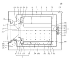
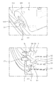
도 1은 본 발명 의류처리장치의 단면도이다.
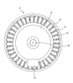
도 2는 본 발명에 구비되는 구동부 및 감지부를 도시한 것이다.
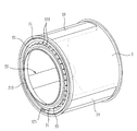
도 3은 본 발명에 구비되는 드럼 및 밸런성유닛의 결합구조를 도시한 것이다.
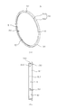
도 4는 본 발명에 구비되는 밸런서를 도시한 것이다.
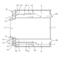
도 5는 본 발명에 구비되는 유로부를 도시한 것이다.
도 6은 본 발명에 구비되는 가이더를 도시한 것이다.
도 7은 본 발명에 구비되는 유로부, 가이더 및 밸런서의 결합구조를 도시한 것이다.
도 8 내지 도 12는 본 발명의 언밸런스 감쇄과정을 도시한 것이다.
도 13은 본 발명의 다른 실시예를 도시한 것이다.1 is a cross-sectional view of the clothes processing apparatus of the present invention.
FIG. 2 illustrates a driving unit and a sensing unit according to the present invention.
Fig. 3 shows a coupling structure of the drum and balance unit according to the present invention.
FIG. 4 shows a balancer according to the present invention.
Fig. 5 shows a flow path portion provided in the present invention.
6 shows a guider provided in the present invention.
Fig. 7 shows a coupling structure of a flow path portion, a guider, and a balancer according to the present invention.
Figures 8 to 12 illustrate the unbalance attenuation process of the present invention.
Fig. 13 shows another embodiment of the present invention.
이하에서는 첨부된 도면을 참고하여 본 발명의 바람직한 실시예를 상세하게 설명한다.Hereinafter, preferred embodiments of the present invention will be described in detail with reference to the accompanying drawings.
특별한 정의가 없는 한 본 명세서의 모든 용어는 본 발명이 속하는 기술분야의 통상의 기술자가 이해하는 당해 용어의 일반적 의미와 동일하고, 만약 본 명세서에 사용된 용어가 당해 용어의 일반적 의미와 충돌하는 경우에는 본 명세서에 사용된 정의에 따른다.Unless defined otherwise, all terms herein are the same as the general meaning of the term as understood by one of ordinary skill in the art to which this invention belongs, and if the terms used herein conflict with the general meaning of the term Are as defined herein.
한편, 이하에 기술될 장치의 구성이나 제어방법은 본 발명의 실시예를 설명하기 위한 것일 뿐 본 발명의 권리범위를 한정하기 위함은 아니며, 명세서 전반에 걸쳐서 동일하게 사용된 참조번호들은 동일한 구성요소들을 나타낸다.It is to be understood that the present invention is not limited to the details of the embodiments described below, .
도 1에 도시된 바와 같이, 본 발명 의류처리장치(100)는 외관을 형성하는 캐비닛(1), 상기 캐비닛 내부에 구비되어 세탁수가 저장되는 터브(2), 상기 터브 내부에 회전 가능하게 구비되며 세탁물이 저장되는 드럼(3), 상기 드럼을 회전시키는 구동부(4), 드럼의 언밸런스를 유발하는 세탁물과 반대방향에 있는 드럼 영역의 무게를 증가시킴으로써 언밸런스를 제어하는 밸런싱유닛(5)을 포함할 수 있다.As shown in FIG. 1, the
도 1은 물을 이용하여 세탁물의 세탁만 수행하는 의류처리장치(100)를 도시한 것이다. 따라서, 세탁물의 세탁 및 건조가 가능한 의류처리장치라면 상기 드럼(3)에 공기를 공급하는 공기공급부(미도시)가 상기 캐비닛(1)의 내부에 더 구비되어야 할 것이다.FIG. 1 shows a
한편, 세탁물의 건조만을 목적으로 하는 의류처리장치의 경우, 도 1에 도시된 터브(2)는 의류처리장치에서 제거되어도 무방하나 드럼(3)에 공기를 공급하기 위한 공기공급부(미도시)는 포함하도록 구비되어야 할 것이다.On the other hand, in the case of a garment treating apparatus intended only for drying laundry, the
이하에서는 설명의 편의를 위해 도 1에 도시된 세탁만을 수행하는 의류처리장치(100)의 구조를 기준으로 설명한다.Hereinafter, for convenience of explanation, the structure of the
상기 캐비닛(1)은 세탁물이 출입되는 투입구(11), 상기 캐비닛에 회전 가능하게 구비되어 상기 투입구(11)를 개폐하는 도어(13)를 포함한다.The
상기 터브(2)는 내부가 비어있는 원통형상으로 구비될 수 있고, 상기 투입구(11)에 연통하는 터브개구부(21)를 포함하도록 구비된다.The
한편, 상기 터브개구부(21)와 투입구(11) 사이에는 가스켓(23)이 구비되는데, 상기 가스켓(23)은 터브 내부의 세탁수가 터브의 외부로 유출되는 것을 방지하고 터브의 진동이 캐비닛으로 전달되는 것을 방지하는 수단이다.A
상기 드럼(3)은 내부가 비어있는 원통형상의 드럼바디가 상기 터브(2) 내부에 위치됨으로써 구비될 수 있다.The
상기 드럼(3)의 전방면(31, 드럼바디의 전방면)에는 상기 투입구(11) 및 터브개구부(21)에 연통하는 드럼개구부(311)가 구비되고, 상기 드럼의 원주면에는 드럼의 내부를 터브의 내부와 연통시키는 다수의 관통홀(37)이 구비된다.A
따라서, 사용자는 투입구(11)를 통해 세탁물을 드럼(3) 내부에 공급하거나 드럼 내부에서 인출할 수 있다. 또한, 상기 관통홀(37)에 의해 터브(2) 내부의 세탁수는 드럼(3) 내부에 저장된 세탁물로 이동할 수 있고, 세탁물에 저장된 세탁수는 터브(2)로 배출될 수 있게 된다.Therefore, the user can supply the laundry into the
상기 구동부(4)는 드럼(3)을 터브(2) 내부에서 회전시킬 수 있는 한 다양한 형태로 구비될 수 있는데, 도 1은 터브(2)의 후방면에 구비되어 터브의 후방면을 관통하는 회전축을 통해 드럼(3)을 회전시키는 직결식 모터를 일례로 도시한 것이다.The driving
도 1에 도시된 바와 같이 상기 구동부(4)는 터브(2)의 후방면에 고정되는 스테이터(45), 터브(2)의 후방면을 관통하여 드럼(3)의 후방면(33)에 고정되는 회전축(46), 상기 스테이터를 감싸도록 구비되되 상기 회전축(46)이 고정되는 로터(41), 상기 로터에 고정되며 상기 스테이터(45)가 제공하는 자기장에 의해 로터(41)를 회전시키는 다수의 영구자석(43)으로 구비될 수 있다.1, the driving
도 2에 도시된 바와 같이, 상기 영구자석은 로터(41)의 내주면에 다수 개가 일정한 간격을 가지도록 고정되며, 상기 스테이터(45)는 스테이터(45)를 감싸도록 구비되는 인슐레이터(47)에 의해 절연된다.2, the permanent magnets are fixed on the inner circumferential surface of the
상기 인슐레이터(47)에는 영구자석(43)의 자력을 감지함으로써 로터(41)의 회전속도, 회전방향, 회전각도 등을 감지하는 감지부(6, 홀센서 등)가 구비될 수 있는데 상기 감지부에 대한 설명은 후술한다.The
상기 밸런싱유닛(5)은 드럼의 회전중심을 기준으로 언밸런스를 유발시키는 세탁물이 위치된 드럼영역과 대칭되는 영역에 위치된 드럼의 무게를 증가시킴으로써 드럼의 언밸런스를 감쇄시키는 수단이다.The
상기 밸런싱유닛(5)은 드럼의 전방면(31)에 구비될 수도 있고 드럼의 후방면(33)에 구비될 수도 있다. 다만, 이하에서는 설명의 편의를 위해 밸런싱유닛(5)이 드럼의 전방면(31)에 구비된 경우를 기준으로 설명한다.The
도 3에 도시된 바와 같이, 상기 밸런싱유닛(5)은 드럼에 고정되되 일정한 간격으로 서로 이격되어 구비되는 적어도 3개의 밸런서(55), 상기 터브(2) 또는 가스켓(23)에 구비되어 상기 드럼의 전방면(31)을 향해 액체를 분사하는 공급부(57), 상기 드럼의 전방면(31)에 구비되어 상기 공급부에서 공급되는 액체를 밸런서(55)로 안내하는 유로부(51, 52)로 구비될 수 있다.3, the
밸런서(55)의 개수는 밸런서(55)가 드럼 원주면에 동일한 각도만큼 서로 이격되어 구비되는 한 다양하게 구비될 수 있다. 다만, 이하에서는 설명의 편의를 위해 3개 또는 4개의 밸런서(55)가 구비된 경우를 기준으로 설명한다.The number of
상기 밸런서(55)는 드럼(3)의 외주면에 고정되어 구비될 수도 있지만 도 3에 도시된 바와 같이 드럼(3)의 내주면에서 돌출되도록 구비될 수 있다.The
상기 밸런서(55)가 드럼의 내주면에 돌출되어 구비되면, 본 발명에 구비된 밸런서(55)는 언밸런스를 해소하기 위한 수단일 뿐만 아니라 드럼의 회전 시 드럼 내부에 저장된 세탁물을 교반시키는 수단으로써도 기능할 수 있을 것이다. 따라서, 이하에서는 드럼의 내주면에 밸런서(55)가 구비된 경우를 기준으로 설명한다.If the
도 4에 도시된 바와 같이, 상기 밸런서(55)는 드럼의 내측 원주면에 고정되어 액체가 저장되는 저장부(551, 552), 상기 저장부로 액체가 유입되는 유입구(557), 상기 저장부(551, 552) 내부를 드럼(3)의 외부와 연통시켜 저장부 내부의 액체가 드럼(3)의 외부로 배출되도록 하는 배출구(558)를 포함한다.4, the
상기 저장부는 드럼(3)의 내측 원주면에 고정되는 저장부 바디(551), 상기 저장부 바디의 상부에 고정되는 커버(552)로 구비될 수 있다.The storage unit may include a
상기 커버(552)는 저장부 바디(551)에 구비된 고정부(555)에 의해 저장부 바디와 일정한 간격을 유지할 수 있고, 상기 커버(552)에는 저장부 바디(551) 내부에 저장된 액체를 드럼의 외부로 배출시키는 배출구(558)가 구비된다.The
한편, 상기 저장부 바디(551)와 상기 커버(552)는 볼트와 같은 체결부재를 통해 결합될 수 있는데, 이를 위해 상기 커버(552)에는 체결부재가 커버(552)를 관통하여 고정부(555)에 삽입될 수 있도록 하는 체결부재 관통홀(5521)이 더 구비될 수 있다.The
나아가, 상기 밸런서(55)는 상기 저장부(551, 552) 내부를 드럼(3)의 회전중심을 향하는 위치에 구비된 상부공간과 드럼의 원주면을 향하는 위치에 구비된 하부공간으로 구분하는 가이드 플레이트(559)를 더 포함할 수 있다.Further, the
드럼(3)의 전방면(31)에 세탁물이 밀집되어 언밸런스가 유발(드럼의 길이방향 평면에 발생되는 언밸런스)될 경우, 상기 가이드 플레이트(559)가 없으면 저장부(551, 552)로 유입되는 액체는 저장부의 전방면을 채운 뒤 후방면을 향해 이동할 것이므로 드럼의 언밸런스를 가중시킬 위험이 있다.When the laundry is densely packed on the
따라서, 상기 가이드 플레이트(559)는 유입구(557)를 통해 저장부(551, 552)로 유입되는 액체가 저장부 바디(551)의 중심에서 저장부 바디(551)의 가장자리로 공급되도록 하여 상술한 문제를 방지하는 수단이 된다.Accordingly, the
상기 가이드 플레이트(559)는 저장부 바디(551)의 너비와 동일한 너비를 가지되 저장부 바디(551)의 길이보다는 짧은 길이(저장부 바디 길이의 절반에 해당하는 길이 등)를 가지도록 구비된다.The
또한, 가이드 플레이트(559)는 상기 유입구(557)와 동일한 높이에 구비되거나 상기 유입구(557)보다 낮은 높이에 구비되어야 하며, 가이드 플레이트(559)에는 상기 유입구(557)에 연결되어 유입구(557)로 공급되는 액체를 안내하는 가이드 리브(5591)가 더 구비될 수 있다.The
한편, 상기 가이드 플레이트(559)는 상기 가이드 리브(5591)의 반대방향에 구비되어 드럼의 후방면(33)을 향해 연장되는 한 쌍의 연장부(5593)가 더 구비될 수 있는데, 상기 연장부(5593)는 서로 소정거리 이격되도록 구비됨이 바람직하다.The
상기 저장부 바디(551)에는 드럼의 회전축과 나란한 방향(드럼의 길이방향, 저장부의 길이방향)을 따라 저장부 바디(551)의 내부공간을 다수 개의 공간으로 분리시키는 저장부 격벽(553), 상기 저장부 격벽에 의해 구분되는 각 공간들을 서로 연통시키는 격벽연통부(554)가 더 구비될 수 있다.The
가이드 플레이트(559)를 통해 저장부(551, 552)에 공급되어 저장부 바디(551)의 중심에서 저장부 바디의 가장자리로 이동하는 액체의 속도를 줄임으로써 세탁물이 드럼의 전방면(31)에 밀집되어 언밸런스가 유발되는 경우 저장부(551, 552)로 공급되는 액체에 의해 언밸런스가 가중되는 것을 방지하기 위함이다.The laundry is supplied to the
상기 유로부는 도 5에 도시된 바와 같이 드럼의 전방면(31)에 고정되는 제1유로(51)만으로 구비될 수도 있고, 도 13에 도시된 바와 같이 드럼의 전방면에 고정되는 제1유로(51) 및 제2유로(52)로 구비될 수도 있다.5, the flow path may include only the
도 5를 참고하여 전자를 먼저 설명하자면, 상기 제1유로(51)는 상기 드럼의 전방면(31)에서 연장된 뒤 상기 드럼개구부(311)를 향해 절곡되어 액체가 저장되는 제1유로 바디(511), 상기 제1유로 바디(511) 내부를 밸런서(55)와 동일한 개수의 공간(S1, S2, S3)으로 구분하는 제1유로 격벽(515)으로 구비될 수 있다.5, the
상기 제1유로 바디(511)는 상기 드럼개구부(311)의 원주면이 수용될 수 있도록 드럼개구부(311)의 지름보다 큰 지름을 가진 링형상으로 구비되며, 상기 드럼의 전방면(31)에 고정된다.The
즉, 상기 제1유로 바디(511)는 드럼의 전방면(31)에 고정되되 드럼개구부(311)의 지름보다 큰 지름을 가진 링 형상의 제1바디(5111), 상기 제1바디(5111)에서 상기 드럼개구부(311)를 향해(드럼의 회전중심을 향해) 연장되는 제1플랜지(5113)로 구비될 수 있다.That is, the first
따라서, 공급부(57)를 통해 제1유로(51)로 공급되는 액체는 드럼의 전방면(31)과 제1유로 바디(511)가 형성하는 공간에 저장될 수 있다.Therefore, the liquid supplied to the
도 5는 제1바디(5111)와 제1플랜지(5113)가 직각으로 결합된 구조를 도시하고 있지만 이는 일례에 불과하므로 제1바디(5111)와 제1플랜지(5113)의 결합 각은 다양하게 변형되어도 무방하다.5 shows a structure in which the
한편, 앞서 설명한 바와 같이 상기 밸런서(55)의 개수는 밸런서(55)가 드럼 원주면에 동일한 각도만큼 서로 이격되어 구비되는 한 다양하게 구비될 수 있는데 상기 제1유로 격벽(515)은 상기 밸런서(55)의 수와 동일하게 구비된다.As described above, the number of the
즉, 상기 밸런서(55)가 드럼 원주면에 드럼의 회전중심을 기준으로 120도 간격 이격되어 구비되면 상기 제1유로 격벽(515)은 상기 제1유로 바디(511)를 3개의 공간(S1, S2, S3)으로 구분하도록 구비될 것이고, 상기 밸런서(55)가 드럼 원주면에 드럼의 회전중심을 기준으로 90도 간격 이격되어 구비된다면 상기 제1유로 격벽(515)은 제1유로 바디(511)를 4개의 공간으로 구분하도록 구비될 것이다.That is, if the
다만, 이하에서는 설명의 편의를 위해 3개의 밸런서 및 3개의 제1유로 격벽이 구비된 경우를 기준으로 설명한다.Hereinafter, for convenience of explanation, three balancers and three first flow path barrier ribs will be described.
상기 제1유로 격벽(515)들은 드럼의 전방면(31)에 구비되어 각 밸런서(55)에 구비된 유입구(557)를 드럼의 외부와 연통시키는 격벽관통홀(313, 도 7 (b) 참고)에 삽입된다.The first flow
따라서, 제1유로 바디(511)에 구비된 하나의 공간(S1)에 공급된 액체는 3개의 밸런서 중 어느 하나의 밸런서에만 공급되고, 제2공간(S2)에 공급된 액체는 나머지 두 개의 밸런서 중 어느 하나에만 액체를 공급하며, 제3공간(S3)에 공급된 액체는 마지막 남은 밸런서에만 액체를 공급하게 될 것이다.Therefore, the liquid supplied to one space S1 provided in the
상기 공급부(57)는 터브(2)나 가스켓(23)에 고정되어 상기 제1유로(51)에 액체를 공급하는 노즐(571), 상기 노즐에 액체를 공급하는 공급관(573), 제어부(미도시)에 의해 상기 공급관(573)을 개폐하는 밸브(575)로 구비될 수 있다(도 1참고).The
제1유로(51)에 공급되는 액체가 물인 경우, 상기 공급관(573)은 상기 노즐(571)과 캐비닛(1)의 외부에 구비된 급수원(미도시)을 연결하도록 구비될 수 있다.When the liquid supplied to the
또한, 상기 공급관(573)은 터브(2)에 세탁수를 급수하기 위해 터브(2)와 급수원(미도시)을 연결하는 급수관(미도시)에서 분지되도록 구비되어도 무방하다.The
나아가, 상기 밸런싱유닛(5)은 상기 드럼에 고정되어 상기 공급부(57)에서 분사되는 액체가 드럼(3)의 회전방향과 반대방향으로 이동되는 것을 방지하는 가이더(53)를 더 포함할 수 있다.Further, the
언밸런스는 드럼(3)의 회전 중 허용범위를 초과하여 드럼에 발생되는 질량불균형 현상이므로 상기 공급부(57)는 드럼(3)의 회전 중 상기 제1유로(51)를 통해 특정위치에 구비된 상기 밸런서(55)에 액체를 공급함으로써(드럼의 하중을 국부적으로 증가시킴으로써) 언밸런스를 감쇄시킨다.Since the unbalance is a mass unbalance phenomenon that occurs in the drum beyond the permissible range during the rotation of the
한편, 드럼(3)의 회전 중 제1유로(51)로 액체가 공급되면, 제1유로 바디(511) 내부의 액체는 드럼의 전방면(31)과 함께 회전하지 못하고 드럼의 회전방향과 반대방향으로 이동(드럼의 전방면에서 액체가 미끄러짐)될 수 있다.When the liquid is supplied to the
공급부(57)에서 분사된 액체가 드럼(3)의 회전방향과 반대방향으로 이동하면 제1유로(51)에 구비된 다수의 공간(S1, S2, S3) 중 의도하지 않은 공간으로 액체가 공급될 수 있고, 이로 인해 드럼의 언밸런스를 심화시킬 위험이 있는데 상기 가이더(53)는 상술한 문제를 해결하기 위한 수단이다.When the liquid sprayed from the
도 6에 도시된 바와 같이, 상기 가이더(53)는 드럼의 전방면(31)에서 연장된 뒤 상기 제1유로(51)를 향해 절곡되는 가이더 바디(531), 상기 가이더 바디(531) 내부공간을 다수의 공간으로 구분하는 가이더 격벽(535)으로 구비될 수 있다.6, the
상기 가이더 바디(531)는 드럼개구부(311)의 지름보다는 크고, 제1유로(51)의 지름보다는 작은 지름을 가진 링형상으로 구비되어 드럼의 전방면(31)에 고정되는 바디(5311), 상기 바디(5311)에서 상기 제1유로(51)를 향해(드럼개구부에서 멀어지는 방향을 향해) 연장되는 플랜지(5313)으로 구비될 수 있다.The
상기 바디(5311)는 상기 제1유로(51)와 소정거리 이격되도록 구비되며, 상기 공급부(57)에서 공급되는 액체는 가이더(53)에 충돌한 뒤 제1유로(51)로 공급될 수 있다. 따라서, 상기 플랜지(5313)는 상기 공급부(57)에서 바디(5311)를 향해 분사된 액체가 제1유로(51)를 향하도록 안내하는 수단이 된다.The
상기 가이더 격벽(535)은 상기 가이더 바디(531)의 원주면을 따라 다수 개가 일정한 간격을 유지하도록 구비된다. 이 경우 상기 노즐(571)은 가이더(53)를 향해 액체를 분사하도록 구비됨이 바람직하다.The
즉, 상기 노즐(571)은 터브(2)나 가스켓(23)에서 드럼의 전방면(31)을 향해 연장된 뒤 상기 가이더(53)를 향해 소정각도 절곡되어 노즐(571)에서 공급되는 액체가 하나의 가이더 격벽(535)과 다른 하나의 가이더 격벽(535) 사이의 공간에 유입되도록 구비됨이 바람직하다.That is, the
한편, 상기 가이더 격벽(535)의 수는 구동부에 구비된 영구자석(43)의 수와 동일하게 구비될 수도 있고, 영구자석(43) 수의 절반으로 구비될 수도 있다.The number of the guiding
드럼(3)의 회전속도, 회전각도, 회전방향 등을 감지하기 위해 구비되는 감지부(6)의 각도 분해능은 구동부(4)에 구비된 영구자석(43)의 수에 의해 결정된다.The angular resolution of the sensing unit 6 provided for sensing the rotational speed, the rotational angle, and the rotational direction of the
상기 감지부(6)는 로터(41)의 회전(드럼의 회전) 시 영구자석(43)이 감지부(6)를 통과하였는지 여부에 관한 데이터를 제어부(미도시)에 전송하고, 제어부(미도시)는 감지부(6)가 전송하는 데이터들 사이의 시간 간격을 통해 로터의 회전속도(드럼의 회전속도)를 판단하며, 감지부가 전송하는 데이터의 수나 순서 등을 통해 로터의 회전각도(드럼의 회전각도)를 판단할 수 있기 때문이다.The sensing unit 6 transmits data regarding whether the
따라서, 감지부의 각도 분해능의 의미는 감지부가 검출 가능한 로터의 최소 회전각도로 이해될 수 있다.Therefore, the meaning of the angular resolution of the sensing portion can be understood as the minimum rotation angle of the rotor in which the sensing portion is detectable.
한편, 드럼에 언밸런스가 발생된 경우, 드럼의 회전속도는 드럼의 회전궤적 최고점에서 가장 낮고 드럼의 회전궤적 최저점에서 가장 빠르다. 따라서, 제어부(미도시)는 드럼의 회전속도가 가장 빠른 영역, 드럼의 회전속도가 가장 느린 영역의 반대영역에 언밸런스를 유발하는 세탁물이 집중돼 있다고 판단할 수 있다.On the other hand, when unbalance occurs in the drum, the rotation speed of the drum is lowest at the peak of the rotation locus of the drum and is the fastest at the lowest point of the rotation locus of the drum. Accordingly, the control unit (not shown) can determine that the laundry that causes unbalance is concentrated in the region where the rotational speed of the drum is the highest, and the region opposite the region where the rotational speed of the drum is the slowest.
만약, 가이더 격벽(535)의 수가 영구자석(43)의 수와 동일하게 구비되면, 제어부(미도시)는 공급부(57)를 통해 제1유로(51)로 공급되는 액체가 언밸런스를 유발하는 세탁물이 집중된 드럼영역의 반대방향에 위치된 밸런서(55)로 정확하게 공급할 수 있는 효과가 있다.If the number of the
다만, 가이더 격벽(535)의 수가 영구자석(43) 수의 절반으로 구비되면, 공급부(57)를 통해 제1유로(51)로 공급되는 액체가 언밸런스를 유발하는 세탁물이 집중된 드럼영역의 반대방향에 위치된 밸런서(55)로 공급되는 정확도는 다소 낮아지지만 언밸런스의 능동적 제어가 가능함은 실험적으로 확인되었다.If the number of the
한편, 상기 공급부(57)의 위치는 가이더(53)를 향해 액체를 공급할 수 있는 한 터브(2)의 어느 위치에 고정(가스켓의 어느 위치에 고정)되어도 무방하다.On the other hand, the position of the
다만, 상기 감지부(6)와 상기 공급부(57)는 드럼의 회전축(C, 도 1 참고)에 의해 대칭되는 평면(드럼의 길이방향을 따라 형성되고 드럼의 회전축을 지나는 평면)에 구비됨이 바람직하다.The sensing unit 6 and the supplying
예를 들면, 상기 감지부(6)는 로터(41)의 회전궤적 최저점을 지나는 영구자석의 자력을 감지하도록 구비되고, 공급부(57)는 드럼(3)의 회전궤적 최저점을 향해 액체를 공급하도록 구비될 수 있다.For example, the sensing unit 6 is provided to sense the magnetic force of the permanent magnet passing through the lowest point of the rotation locus of the
도 8에 도시된 바와 같이, 본 발명에 구비된 제어부(미도시)는 언밸런스를 유발하는 세탁물(UB)이 노즐(571)을 통과(A)한 때로부터 드럼이 일정각도 회전(B)되면, 기 설정된 시간동안(드럼이 기 설정된 각도만큼 회전할 동안) 액체를 제1유로(51)에 공급함으로써 언밸런스를 감쇄하므로 상술한 감지부(6) 및 공급부(57)의 위치는 이와 같은 제어를 용이하게 하는 효과가 있기 때문이다.As shown in FIG. 8, when the drum UB rotates at a predetermined angle B from when the laundry UB causing unbalance passes through the
이하에서는 도 9 내지 도11을 참고하여 본 발명의 제어과정에 대해 살펴본다.Hereinafter, the control process of the present invention will be described with reference to FIGS. 9 to 11. FIG.
도 9는 언밸런스를 유발하는 세탁물(UB)이 제1밸런서(55a)와 제2밸런서(55b)의 중간(60도)에 위치한 경우 언밸런스 감쇄과정을 도시한 것이다.FIG. 9 shows a process of unbalance attenuation when the laundry UB causing unbalance is located at the middle (60 degrees) between the
드럼(3)의 회전 중 제어부(미도시)는 감지부(6)가 제공하는 데이터에 근거하여 드럼의 회전속도를 측정함으로써 언밸런스의 원인이 되는 세탁물(UB)이 드럼의 어느 영역에 있는지 판단한다.A control unit (not shown) during the rotation of the
이후 제어부는 언밸런스의 원인이 되는 세탁물(UB)이 공급부의 노즐(571)을 통과하였는지 여부를 판단한다.Then, the control unit determines whether the laundry UB causing unbalance has passed through the
언밸런스의 원인이 되는 세탁물(UB)이 노즐(571)을 통과하면 제어부는 드럼이 기 설정된 대기각도(D)만큼 회전되었는지 여부를 판단한다.When the laundry UB causing unbalance passes through the
드럼이 대기각도(D)에 도달되면, 제어부는 공급부의 밸브(575)를 개방하여 노즐(571)이 가이더(53)를 향해 액체를 분사하도록 하는데, 제어부는 드럼(3)이 기 설정된 공급각도(S)만큼 회전될 때까지 제1유로(51)에 액체가 공급되도록 공급부를 제어하게 된다.When the drum reaches the standby angle D, the control unit opens the
밸런서(55)가 드럼의 원주면에 3개 구비되는 경우(각 밸런서는 서로 120도 각도만큼 이격된 경우), 상기 대기각도(D) 및 공급각도(S)는 각 밸런서에 일정한 양의 액체를 일정한 비율로 공급할 수 있는 한 다양하게 설정될 수 있다.When three
즉, 노즐(571)의 단위시간당 액체 공급량을 최소화할 경우(첫 번째 밸런서가 노즐을 통과한 뒤 두 번째 밸런서가 노즐에 도달할 때까지 액체를 공급함으로써 두 번째 밸런서에 적절한 양의 액체를 채울 수 있는 단위시간 당 액체 공급량), 상기 대기각도(D)는 60도로 설정되고 상기 공급각도(S)는 120도로 설정될 수 있다.That is, when the liquid supply amount per unit time of the
그러나, 노즐에서 공급되는 액체의 양을 증가시킨다면 상기 대기각도(D)는 증가시키고, 상기 공급각도(S)는 짧게 설정할 수 있다.However, if the amount of liquid supplied from the nozzle is increased, the waiting angle D can be increased and the supply angle S can be set shorter.
한편, 상기 밸런서(55)가 상기 드럼의 원주면을 따라 서로 90도 각도 이격되도록 구비된다면, 상기 대기각도(D) 및 상기 공급각도(S)는 각각 90도로 설정될 수 있고, 상기 밸런서(55)가 상기 드럼의 원주면을 따라 서로 60도씩 이격되어 구비되면 대기각도(D) 및 공급각도(S)는 120도와 60도로 설정될 수 있다.The standby angle D and the supply angle S may be set to 90 degrees, respectively, if the
또한, 상기 밸런서(55)가 상기 드럼의 원주면을 따라 서로 45도씩 이격되도록 구비된다면, 상기 대기각도(D) 및 상기 공급각도(S)는 135도 및 45도로 설정될 수 있고, 상기 밸런서(55)가 상기 드럼의 원주면을 따라 서로 36도씩 이격되어 구비된다면 상기 대기각도(D) 및 상기 공급각도(S)는 144도 및 36도로 설정될 수 있을 것이다.The standby angle D and the supply angle S may be set to 135 degrees and 45 degrees if the
이하에서는 설명의 편의를 위해, 노즐(571)의 단위시간당 액체공급량이 첫 번째 밸런서가 노즐을 통과한 뒤 두 번째 밸런서가 노즐에 도달할 때까지 액체를 공급함으로써 두 번째 밸런서에 액체를 가득 채울 수 있도록 설정된 경우를 기준으로 설명한다.Hereinafter, for convenience of explanation, the liquid supply amount per unit time of the
도 9에 도시된 바와 같이 제1밸런서(55a)와 제2밸런서(55b)의 중간에 세탁물이 집중된 경우 액체는 제3밸런서(55c)에 모두 공급되어야만 언밸런스를 유발하는 힘(F ub)을 감쇄시킬 수 있다.9, when the laundry is concentrated in the middle between the
즉, 노즐(571)을 통해 제1유로(51)에 공급되는 액체는 제1유로 바디(511)의 제1영역(S1)에 모두 공급되어야만 드럼의 언밸런스를 제어할 수 있다.That is, the unbalance of the drum can be controlled only when the liquid supplied to the
이를 위해 제어부(미도시)는 드럼의 일부영역에 집중된 세탁물(언밸런스를 유발하는 힘, F ub)이 노즐(571)로부터 60도 회전된 때로부터 드럼이 120도 회전할 때까지 노즐(571)을 통해 제1유로(51)에 액체를 공급하게 된다.For this, the controller (not shown) controls the
이때, 노즐(571)에서 분사된 액체는 가이더(53)에 의해 드럼의 회전방향과 반대방향으로 이동하는 것이 방지되므로 본 발명은 노즐에서 분사된 액체가 제1유로 바디(511)에 구비된 공간(S1, S2, S3) 중 원하지 않은 공간(S2나 S3)으로 유입되는 것을 방지할 수 있다.Since the liquid sprayed from the
따라서, 본 발명은 드럼의 언밸런스을 능동적으로 해소시킬 뿐만 아니라 드럼 내부의 세탁물도 교반시키는 의류처리장치를 제공하는 효과가 있다.Therefore, it is an object of the present invention to provide a clothes processing apparatus which not only actively resolves unbalance of a drum but also stirs laundry inside the drum.
한편, 밸런서(55)에 공급된 액체는 배출구(558)를 통해 드럼(3)의 외부로 배출되는데 이는 드럼 내부에 저장된 세탁물에 액체가 공급되는 것을 방지하기 위함이다.On the other hand, the liquid supplied to the
노즐(571)이 제공하는 액체는 밸런서(55)가 드럼의 회전궤적 최저점을 향해 이동하는 동안 밸런서(55) 내부로 공급되고, 드럼의 회전에 의해 밸런서(55)가 드럼의 회전궤적 최고점을 향해 이동하는 동안 배출구(558)를 통해 터브로 배출된다.The liquid provided by the
밸런서(55)에 공급된 액체가 일정시간 밸런서 내부에 저장되어야만 언밸런스의 감쇄가 가능하기 때문이며, 이와 같은 효과는 밸런서(55)에 구비된 배출구(558)가 가이드 플레이트(559)보다 높은 위치에 구비(커버(552)에 구비)되기 때문에 가능하다.This is because the
도 10은 언밸런스를 유발하는 힘(F ub, 언밸런스를 유발하는 세탁물)이 제1밸런서(55a)에 있는 경우 언밸런스의 제어과정을 도시한 것이다.FIG. 10 shows a process of controlling unbalance when the unbalance generating force (Fub, laundry causing unbalance) is present in the
도 10의 경우, 액체는 제2밸런서(55b) 및 제3밸런서(55c)에 동일한 양이 공급되어야만 드럼의 언밸런스를 감쇄시킬 수 있다.In the case of FIG. 10, the liquid can attenuate the unbalance of the drum only if the same amount is supplied to the
이를 위해 제어부(미도시)는 언밸런스를 유발하는 세탁물(F ub)이 노즐(571)을 통과한 뒤 대기각도(D)만큼 드럼(3)이 회전되었는지 여부를 판단하고, 언밸런스 유발 세탁물(F ub)이 노즐(571)을 통과한 때로부터 드럼(3)이 공급각도(S)까지 회전할 동안 제1유로(51)에 액체를 공급한다.The control unit (not shown) determines whether the
제1유로(51)에 구비된 제1유로 격벽들(515)은 제1유로 바디(511) 내부공간을 밸런서(55)의 수와 동일한 수로 구분하고, 각 제1유로 격벽(515)들의 위치는 각 밸런서(55)에 구비된 유입구(557)의 위치와 동일하다.The first
따라서, 드럼이 대기각도(D)만큼 회전된 후 공급각도(S, 제1유로 격벽을 기준으로 대칭되는 각도)만큼 회전되는 동안 노즐(571)에서 공급되는 액체는 제1유로 바디(511)의 제3공간(S3)과 제2공간(S2)에 동일하게 공급될 것이다.Accordingly, the liquid supplied from the
제3공간(S3)에 공급되는 액체는 제3밸런서(55c)로 유입되고, 제2공간(S2)에 공급된 액체는 제2밸런서(55b)로 공급되므로 언밸런서를 유발하는 힘(F ub)은 제2밸런서(55b)와 제3밸런서(55c)에 공급된 액체의 자중(F2, F1)에 의해 감소되거나 상쇄될 것이다.The liquid supplied to the third space S3 flows into the
한편, 언밸런스를 유발하는 세탁물(F ub)의 위치가 도 10과 같더라도 3개의 밸런서가 120도 간격으로 이격된 경우 상기 대기각도(D)는 60도이고, 공급각도(S)는 120도로 설정될 수 있다.10, the waiting angle D is 60 degrees and the supply angle S is 120 degrees when the balancers are spaced apart from each other by an interval of 120 degrees. .
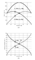
도 12에 도시된 그래프에서 알 수 있듯이 각 밸런서에 공급되는 액체의 양(도 12 (a)), 언밸런스를 유발하는 힘(F ub)을 각 밸런서가 분담하는 비율(도 12 (b))에 을 고려할 때, 두 개의 밸런서에 액체가 공급되어야만 언밸런스를 제어할 수 있는 경우에는 일정한 비율에 따라 두 개의 밸런서 각각에 액체가 공급되어야만 세탁물이 유발하는 힘(F ub)을 상쇄시킬 수 있다.As can be seen from the graph shown in Fig. 12, the ratio of the amount of liquid supplied to each balancer (Fig. 12 (a)) and the force (Fub) The unbalance can be controlled only when the liquid is supplied to the two balancers. In order to control the unbalance, it is necessary to supply the liquid to each of the two balancers at a predetermined ratio to cancel the Fub generated by the laundry.
한편, 노즐(571)의 단위시간당 액체공급량이 첫 번째 밸런서가 노즐을 통과한 뒤 두 번째 밸런서가 노즐에 도달할 때까지 액체를 공급함으로써 두 번째 밸런서에 액체를 가득 채울 수 있도록 설정된 경우, 하나의 밸런서에만 액체를 공급하여 언밸런스를 제어하는 경우(도 9)를 위해 설정된 대기각도(D)와 공급각도(S)는 도 10의 상황에서 도 12의 조건을 만족시킨다.On the other hand, if the liquid supply amount per unit time of the
따라서, 본 발명은 두 개의 밸런서에 액체를 공급하여 언밸런스를 제어하는 경우(도 10)의 대기각도(D) 및 공급각도(S)를 하나의 밸런서에만 액체를 공급하여 언밸런스를 제어하는 경우(도 9)와 동일하게 설정할 수 있다.Accordingly, the present invention is applicable to a case in which unbalance is controlled by supplying a liquid to only one balancer at a standby angle (D) and a supply angle (S) when unbalance is controlled by supplying liquid to two balancers 9).
결론적으로, 본 발명 의류처리장치는 제어방법의 단순화가 가능할 뿐만 아니라 드럼의 회전각도에 근거하여 노즐(571)의 액체 공급시점 및 공급시간을 일정하게 제어함에도 언밸런스를 유발하는 힘(F ub)의 위치에 상관없이 드럼의 언밸런스를 제어할 수 있는 효과가 있다.In conclusion, the clothes processing apparatus of the present invention not only simplifies the control method, but also controls the supply time and the supply time of the
다만, 상술한 대기각도(D) 및 공급각도(S)는 공급부(57)의 단위 시간당 액체 공급량에 따라 상술한 바와 달리 설정될 수 있는데, 상기 공급각도(S)는 제1유로 격벽(515)을 기준으로 대칭되는 각도로 설정되고, 상기 대기각도(D)는 언밸런스를 유발하는 세탁물이 노즐을 통과한 뒤 공급각도(S)에 도달하는데 필요한 각도로 설정될 수 있다.However, the above-described waiting angle D and the supply angle S may be set differently from those described above depending on the liquid supply amount per unit time of the
예를 들어 도 10의 경우, 공급각도(S)가 제1유로 격벽(515)을 기준으로 대칭되는 60도(제1유로 격벽을 기준으로 -30도에서 +30도로 설정)된다면, 상기 대기각도(D)는 90도가 될 것이다.For example, in the case of FIG. 10, if the supply angle S is set to 60 degrees (-30 degrees to +30 degrees relative to the first passage barrier) symmetrical with respect to the first
도 11은 언밸런스를 유발하는 힘(F ub, 언밸런스를 유발하는 세탁물)이 제1밸런서(55a)와 제2밸런서(55b)의 어느 하나의 밸런서로 치우쳐진 경우 언밸런스의 제어과정을 도시한 것이다.11 shows a process of controlling the unbalance when the unbalance generating force (Fub, laundry causing unbalance) is shifted to the balancer of either the
도 11의 경우, 노즐(571)에서 공급되는 액체는 제2밸런서(55b) 및 제3밸런서(55c)에 일정한 비율로 나뉘어 공급되어야만 드럼의 언밸런스를 감쇄시킬 수 있다.11, the liquid supplied from the
이 경우에도, 제어부(미도시)는 언밸런스를 유발하는 세탁물(F ub)이 노즐(571)을 통과한 뒤 대기각도(D)만큼 드럼(3)이 회전되었는지 여부를 판단하고, 언밸런스 유발 세탁물(F ub)이 노즐(571)을 통과한 때로부터 드럼(3)이 공급각도(S)에 도달할 때까지 제1유로(51)에 액체를 공급한다.In this case, the control unit (not shown) determines whether the
드럼이 대기각도(D)만큼 회전된 후 공급각도(S, 제1유로 격벽을 기준으로 대칭되는 각도)만큼 회전되는 동안 노즐(571)에서 공급되는 액체는 제1유로 바디(511)의 제3공간(S3)과 제2공간(S2) 각각에 공급될 것이다.The liquid supplied from the
앞서 설명한 바와 같이, 3개의 밸런서(33)가 드럼의 원주면에 구비되고, 대기각도(D)와 공급각도(S)가 60도 및 120도로 각각 설정되면, 본 발명 의류처리장치(100)는 언밸런스를 유발하는 힘(F ub)의 위치에 상관없이 도 12의 조건을 만족하는 양의 액체를 각 밸런서(55)에 공급할 수 있다.As described above, when three
즉, 언밸런스를 유발하는 세탁물(F ub)이 노즐(571)을 통과한 시점으로부터 드럼이 60도 회전한 후 제1유로 바디(511)에 드럼이 120도 회전할 동안 액체를 공급하면, 제2공간(S2)에 공급되는 액체의 양과 제3공간(S3)에 공급되는 액체의 양이 언밸런스를 유발할 시키는 힘(F ub)을 상쇄시키는 방향의 힘을 발생되도록 조절된다.That is, when the drum F is rotated 60 degrees from the point of time when the laundry Fub which has caused unbalance passes through the
도 9 내지 도 12에서 설명된 제어방법은 드럼의 회전각도를 기준으로 노즐(571)의 액체공급 시점 및 공급시간을 제어하는 경우를 설명한 것이지만 본 발명은 언밸런스를 유발하는 세탁물이 노즐(571)을 통과한 시점을 기준으로 설정되는 대기시간 및 공급시간을 통해 드럼의 언밸런스를 제어할 수도 있다.The control method described with reference to FIGS. 9 to 12 has been described for controlling the liquid supply time and supply time of the
즉, 제어부(미도시)는 언밸런스를 유발하는 세탁물이 노즐을 통과한 뒤 기 설정된 대기시간(D)이 경과하였는지 여부를 판단하고, 대기시간이 경과된 때로부터 기 설정된 공급시간(S) 동안 노즐(571)이 제1유로(51)에 액체를 공급하도록 제어할 수 있다.That is, the control unit (not shown) determines whether or not a predetermined waiting time D has elapsed after the laundry causing unbalance has passed through the nozzle, and determines whether or not the predetermined time (571) to supply the liquid to the first flow path (51).
이 경우, 상기 대기시간(D) 및 공급시간(S)은 드럼의 회전속도(RPM) 및 공급부(57)의 단위시간당 액체 공급량에 따라 달라질 수 있는데 대기시간(D)은 언밸런스를 유발하는 세탁물이 노즐(571)을 통과한 후 60도 회전하는데 걸리는 시간으로 설정되고, 공급시간(S)은 대기시간이 종료된 후 드럼이 120도 회전하는데 걸리는 시간으로 설정될 수 있다.In this case, the waiting time D and the supplying time S may vary depending on the rotational speed RPM of the drum and the liquid supply amount per unit time of the supplying
도 8 (b)를 참고로 설명하면, 드럼이 150RPM으로 회전하는 경우 드럼이 1회전하는데 걸리는 시간은 0.4초이므로 3개의 밸런서(55)가 드럼의 원주면에 구비될 경우 대기시간(D)는 약 0.06초, 공급시간(S)은 약 0.13초로 설정될 수 있다.Referring to FIG. 8 (b), when the drum rotates at 150 RPM, the time taken for the drum to make one revolution is 0.4 second. Therefore, when three
도 13은 본 발명 의류처리장치(100)의 다른 실시예를 도시한 것으로, 본 실시예는 유로부가 제1유로(51) 및 제2유로(52)로 구비되고, 공급부(57)는 제1유로(51)에 액체를 공급하는 제1공급구(57a) 및 제2유로(52)에 액체를 공급하는 제2공급구(57b)로 구비되며, 밸런서(55)는 제1유로(51)에서 공급되는 액체가 유입되는 제1유입구(5571) 및 제2유로(52)에서 공급되는 액체가 유입되는 제2유입구(5573)를 포함하는 것이 특징이다.Fig. 13 shows another embodiment of the
이하에서는 도 1의 구조와 구별되는 특징을 기준으로 본 실시예에 대해 설명한다.Hereinafter, the present embodiment will be described on the basis of features different from the structure of FIG.
본 실시예에 구비된 밸런서(55)는 저장부 바디(551)가 저장부 격벽(553)에 해 드럼의 전방면(31)에 위치한 전방공간(F), 드럼의 후방면에 위치한 후방공간(R)으로 구분된다.The
상기 전방공간(F)은 가이드 플레이트(559)에 의해 드럼(3)의 회전중심에 인접한 상부공간과 드럼(3)의 원주면에 인접한 하부공간으로 구비되며, 상기 제1유입구(5571)는 가이드 플레이트(559)의 상부에 위치된 공간(상부공간)에 연통하고, 상기 제2유입구(5573)은 가이드 플레이트(559)의 하부에 위치된 공간(하부공간)에 연통하도록 구비된다.The front space F is provided with an upper space adjacent to the rotation center of the
상기 제1유로(51)는 드럼의 전방면(31)에서 제1공급구(57a)를 향해 연장된 뒤 절곡되어 구비되는 제1유로 바디(511), 상기 제1유로 바디를 밸런서의 수와 동일한 수의 공간으로 구분하는 제1유로 격벽(515)으로 구비된다.The
상기 제1유로 격벽(515)은 드럼의 전방면(31)을 관통하여 상기 제1유입구(5571)에 삽입된다. 따라서, 제1공급구(57a) 및 가이더(53, 제1가이더)를 통해 제1유로(51)에 공급되는 액체는 가이드 플레이트(559)에 의해 밸런서의 후방공간(R)에만 공급될 것이다.The
한편, 상기 제2유로(52)는 드럼의 전방면(31)에서 제2공급구(57b)를 향해 연장된 뒤 상기 드럼개구부(311)를 향해 절곡되어 구비되는 제2유로 바디(521), 상기 제2유로 바디(521)를 상기 밸런서(55)와 동일한 수의 공간으로 구분하는 제2유로 격벽(525)으로 구비된다.The
상기 제2유로 바디(521)는 제1유로 바디(511)와 동일한 구조(드럼에 고정되는 제2바디, 제2바디에서 드럼개구부를 향해 절곡된 제2플랜지)로 구비되지만 제1유로 바디(521) 보다 큰 지름을 가지는 것이 특징이다.The
상기 제2유로 격벽(525)은 드럼의 전방면(31)을 관통하여 상기 제2유입구(5573)에 삽입된다. 따라서, 제2공급구(57b)를 통해 제2유로(52)에 공급되는 액체는 밸런서의 전방공간(F)에만 공급된다.The second flow
이 경우, 상기 제2유로 바디(521)를 향하는 제1유로 바디(511)의 원주면에는 제2공급구(57b)에서 공급되는 액체가 드럼의 회전방향과 반대방향으로 이동하는 것을 방지하는 제2가이더(미도시)가 구비될 수도 있다.In this case, on the circumferential surface of the
본 실시예에 따른 의류처리장치는 밸런서(55)의 전방과 후방으로 액체를 동시에 공급함으로써 밸런서로 유입되는 액체에 의한 언밸런스 발생을 방지하고, 밸런서로 유입되는 액체에 의해 언밸런스가 가중되는 현상을 방지할 수 있다.The clothes processing apparatus according to the present embodiment prevents the unbalance caused by the liquid flowing into the balancer by simultaneously supplying the liquid to the front and rear of the
또한, 본 실시예는 제1공급구(57a)와 제2공급구(57b)를 선택적으로 개방함으로써 드럼(3)의 전방에만 세탁물이 집중된 경우나 드럼(3)의 후방에만 세탁물이 집중된 경우 발생되는 언밸런스(드럼의 길이방향 평면에 발생하는 언밸런스)도 제어할 수 있는 효과가 있다.In this embodiment, when the laundry is concentrated only in the front of the
본 발명은 다양한 형태로 변형되어 실시될 수 있을 것인바 상술한 실시예에 그 권리범위가 한정되지 않는다. 따라서 변형된 실시예가 본 발명 특허청구범위의 구성요소를 포함하고 있다면 본 발명의 권리범위에 속하는 것으로 보아야 할 것이다.The present invention may be embodied in various forms without departing from the scope of the invention. Accordingly, it is intended that the present invention cover the modifications and variations of this invention provided they come within the scope of the appended claims and their equivalents.
1: 캐비닛 2: 터브 3: 드럼
4: 구동부 5: 밸런싱유닛 51: 제1유로
511: 제1유로 바디 5111: 제1바디 5113: 제1플랜지
515: 제1유로 격벽 52: 제2유로 53: 가이더
531: 가이더 바디 5311: 바디 5313: 플랜지
535: 가이더 격벽 55: 밸런서 551: 저장부 바디
552: 커버 553: 저장부 격벽 554: 격벽 연통부
555: 고정부 557: 유입구 558: 배출구
559: 가이드 플레이트 5591: 가이드 리브 5593: 연장부
57: 공급부 6: 감지부1: cabinet 2: tub 3: drum
4: driving unit 5: balancing unit 51: first flow path
511: first flow body 5111: first body 5113: first flange
515: first flow path barrier 52: second flow path 53: guider
531: Gauge body 5311: Body 5313: Flange
535: guider bulkhead 55: balancer 551: storage body
552: cover 553: storage partition wall 554: partition wall communication portion
555: Fixing portion 557: Inlet port 558: Outlet port
559: Guide plate 5591: Guide rib 5593: Extension part
57: supply part 6:
Claims (20)
상기 캐비닛 내부에 회전 가능하게 구비되어 세탁물이 저장되고, 상기 투입구에 연통하는 드럼개구부가 구비된 드럼;
상기 드럼에 액체를 공급하여 상기 드럼의 하중을 국부적으로 증가시킴으로써 상기 드럼에 발생된 언밸런스를 감쇄시키는 밸런싱유닛;을 포함하는 것을 특징으로 하는 의류처리장치.A cabinet having an inlet through which laundry is introduced;
A drum rotatably installed in the cabinet for storing laundry, and having a drum opening communicating with the inlet;
And a balancing unit for supplying a liquid to the drum to locally increase a load of the drum to thereby attenuate the unbalance generated in the drum.
상기 밸런싱유닛은
액체가 공급되는 공급부;
상기 드럼에 구비되어 상기 공급부에서 공급되는 액체가 저장되고, 상기 드럼의 회전중심을 기준으로 서로 동일한 각도만큼 이격되어 구비되는 적어도 3개의 밸런서;를 포함하는 것을 특징으로 하는 의류처리장치.The method according to claim 1,
The balancing unit
A supply part for supplying liquid;
And at least three balancers provided on the drum and storing the liquid supplied from the supply unit and spaced apart from each other by the same angle with respect to the center of rotation of the drum.
상기 밸런싱유닛은
상기 드럼에 구비되어 상기 공급부에서 공급되는 액체가 상기 드럼에 발생된 언밸런스를 상쇄시키는 방향에 위치된 밸런서로 이동하도록 안내하는 유로부;를 더 포함하는 것을 특징으로 하는 의류처리장치.3. The method of claim 2,
The balancing unit
And a flow path portion provided on the drum and guiding the liquid supplied from the supply portion to move to a balancer positioned in a direction for canceling the unbalance generated in the drum.
상기 유로부는
상기 드럼에서 상기 공급부를 향해 연장된 뒤 상기 드럼의 회전중심을 향해 절곡되어 액체가 수용되는 제1유로 바디와,
상기 제1유로 바디를 상기 밸런서와 동일한 수의 공간으로 구분하고, 하나의 공간에 유입된 액체는 하나의 밸런서로만 유입되도록 하는 제1유로 격벽;을 포함하는 것을 특징으로 하는 의류처리장치.The method of claim 3,
The flow-
A first channel body extending from the drum toward the supply unit and bent toward the center of rotation of the drum to receive liquid;
And a first flow path partition wall dividing the first flow path body into the same number of spaces as the balancer and allowing the liquid flowing into one space to flow into only one balancer.
상기 공급부에서 공급되는 액체를 상기 제1유로 바디로 안내하고, 상기 공급부에서 공급된 액체가 상기 드럼의 회전방향과 반대방향으로 이동하는 것을 방지하는 가이더;를 더 포함하는 것을 특징으로 하는 의류처리장치.5. The method of claim 4,
And a guider for guiding the liquid supplied from the supply unit to the first flow path body and preventing the liquid supplied from the supply unit from moving in a direction opposite to the rotating direction of the drum. .
상기 가이더는
상기 드럼에서 연장된 뒤 상기 제1유로 바디를 향해 절곡되어 액체가 수용되는 공간을 제공하는 가이더 바디;
상기 가이더 바디 내부를 다수의 공간으로 구분하고, 상기 공급부에서 공급되는 액체가 상기 가이더 바디 내부에서 상기 드럼의 회전방향과 반대방향으로 이동하는 것을 방지하는 가이더 격벽;을 포함하는 것을 특징으로 하는 의류처리장치.6. The method of claim 5,
The guider
A guider body extending from the drum and bent toward the first flow body to provide a space for receiving liquid;
And a guider baffle dividing the inside of the guider body into a plurality of spaces and preventing the liquid supplied from the supply unit from moving in the direction opposite to the rotating direction of the drum inside the guider body Device.
상기 밸런서는
상기 드럼의 내주면에 고정되며 액체가 저장되는 공간을 제공하는 저장부;
상기 저장부에 구비되어 상기 제1유로 격벽을 통해 안내되는 액체가 유입되는 유입구;
상기 저장부 내부공간을 상기 드럼의 회전중심을 향하는 상부공간과 상기 드럼의 내주면을 향하는 하부공간으로 구분시키고, 상기 유입구를 통해 유입되는 액체가 상기 저장부의 중심에서 상기 저장부의 가장자리를 향해 이동하도록 하는 가이드 플레이트;를 포함하는 것을 특징으로 하는 의류처리장치.7. The method according to any one of claims 4 to 6,
The balancer
A storage unit fixed to an inner circumferential surface of the drum and providing a space in which liquid is stored;
An inlet through which the liquid guided through the first passage barrier wall flows into the storage unit;
The inner space of the storage part is divided into an upper space facing the rotation center of the drum and a lower space facing the inner circumferential surface of the drum and allowing the liquid flowing through the inlet to move from the center of the storage part toward the edge of the storage part And a guide plate for guiding the clothes.
상기 밸런서는
상기 저장부와 상기 드럼의 외부를 연통시키도록 구비되어 상기 저장부 내부의 액체를 상기 드럼의 외부로 배출시키는 배출구;를 더 포함하는 것을 특징으로 하는 의류처리장치.8. The method of claim 7,
The balancer
And a discharge port provided to communicate the storage section and the outside of the drum to discharge the liquid inside the storage section to the outside of the drum.
상기 밸런서는
상기 저장부의 하부공간을 상기 저장부의 길이방향을 따라 형성되는 다수개의 공간으로 구분시키는 저장부 격벽;
상기 저장부 격벽에 구비되어 상기 저장부 격벽에 의해 구분되는 공간들을 서로 연통시키는 격벽 연통부;를 더 포함하는 것을 특징으로 하는 의류처리장치.9. The method of claim 8,
The balancer
A storage partition wall dividing the lower space of the storage unit into a plurality of spaces formed along the longitudinal direction of the storage unit;
Further comprising: a partition wall communicating portion provided in the storage portion bulkhead to communicate spaces defined by the storage portion bulkhead with each other.
상기 드럼에 언밸런스를 유발시키는 세탁물의 위치를 감지를 감지하는 감지부;
언밸런스를 유발시키는 세탁물이 상기 공급부에 도달한 후 상기 드럼이 기 설정된 대기각도만큼 회전되면, 상기 드럼이 기 설정된 공급각도만큼 회전하는 동안 상기 제1유로 바디에 액체가 공급되도록 상기 공급부를 제어하는 제어부;를 포함하는 것을 특징으로 하는 의류처리장치.7. The method according to any one of claims 4 to 6,
A sensing unit for sensing a position of the laundry which causes unbalance in the drum;
A controller for controlling the supply unit to supply the liquid to the first flow body while the drum rotates by a predetermined supply angle when the drum reaches the supply unit after the laundry causing unbalance is rotated by a predetermined waiting angle, And a controller for controlling the operation of the clothes processing apparatus.
상기 밸런서는 상기 드럼의 원주면을 따라 서로 120도 각도 이격되도록 구비되고,
상기 대기각도는 60도로 설정되고, 상기 공급각도는 120도로 설정되는 것을 특징으로 하는 의류처리장치.11. The method of claim 10,
Wherein the balancers are spaced apart from each other by 120 degrees along the circumferential surface of the drum,
Wherein the waiting angle is set to 60 degrees, and the supply angle is set to 120 degrees.
상기 밸런서는 상기 드럼의 원주면을 따라 서로 90도 각도 이격되도록 구비되고,
상기 대기각도 및 상기 공급각도는 각각 90도로 설정되는 것을 특징으로 하는 의류처리장치.11. The method of claim 10,
Wherein the balancers are spaced apart from each other by 90 degrees along the circumferential surface of the drum,
Wherein the waiting angle and the supply angle are set to 90 degrees, respectively.
상기 드럼에 언밸런스를 유발시키는 세탁물의 위치를 감지를 감지하는 감지부;
언밸런스를 유발시키는 세탁물이 상기 공급부에 도달한 후 기 설정된 대기시간이 경과되면, 상기 대기시간의 종료시점부터 기 설정된 공급시간 동안 상기 제1유로 바디에 액체가 공급되도록 상기 공급부를 제어하는 제어부;를 포함하는 것을 특징으로 하는 의류처리장치.7. The method according to any one of claims 4 to 6,
A sensing unit for sensing a position of the laundry which causes unbalance in the drum;
A control unit for controlling the supply unit to supply the liquid to the first flow path body for a predetermined supply time from the end of the standby time when a predetermined waiting time elapses after the laundry causing unbalance reaches the supply unit And wherein the apparatus further comprises:
스테이터, 상기 드럼에 연결되는 회전축이 고정되는 로터, 상기 로터에 구비되며 상기 스테이터의 자기장에 의해 상기 로터를 회전시키는 다수의 영구자석이 구비된 구동부;
상기 영구자석의 자력을 감지하여 상기 드럼의 언밸런스를 유발시키는 세탁물의 위치를 판단하는 감지부;를 더 포함하고,
상기 제1유로 격벽의 수는 상기 영구자석의 수와 동일하게 구비되거나, 상기 영구자석 수의 절반이 되도록 구비되는 것을 특징으로 하는 의류처리장치.7. The method according to any one of claims 4 to 6,
A driving unit having a stator, a rotor fixed to a rotary shaft connected to the drum, and a plurality of permanent magnets provided in the rotor and rotating the rotor by a magnetic field of the stator;
And a sensing unit for sensing a position of laundry for sensing a magnetic force of the permanent magnet to cause unbalance of the drum,
Wherein the number of the first flow path barrier walls is equal to the number of the permanent magnets, or is set to be half the number of the permanent magnets.
상기 감지부는 상기 로터가 형성하는 회전궤전의 최하점을 지나는 상기 영구자석의 자력을 감지하도록 구비되고,
상기 공급부는 상기 드럼이 형성하는 회전궤적의 최하점을 지나는 상기 가이더에 액체를 분사하도록 구비되는 것을 특징으로 하는 의류처리장치.15. The method of claim 14,
Wherein the sensing unit is configured to sense a magnetic force of the permanent magnet passing through a lowermost point of a rotation path formed by the rotor,
Wherein the supplying unit is configured to inject the liquid to the guider passing the lowermost point of the rotational locus formed by the drum.
상기 캐비닛 내부에 회전 가능하게 구비되고, 전방면에 상기 투입구에 연통하는 드럼개구부가 구비된 드럼;
상기 드럼의 회전중심을 기준으로 서로 동일한 각도만큼 이격되어 상기 드럼에 구비되고, 내부공간을 상기 드럼의 전방면을 향하는 전방공간과 상기 드럼의 후방면을 향하는 후방공간으로 구분하여 액체를 저장하는 적어도 3개의 밸런서;
상기 밸런서와 동일한 수로 구분된 공간을 가지며 하나의 공간에 유입된 액체는 하나의 밸런서에 구비된 후방공간으로만 공급하는 제1유로, 상기 밸런서와 동일한 수로 구분된 공간을 가지며 하나의 공간에 유입된 액체는 하나의 밸런서에 구비된 전방공간으로만 공급하는 제2유로를 포함하는 유로부;
상기 제1유로와 상기 제2유로에 액체를 선택적으로 공급 가능한 공급부;를 포함하는 것을 특징으로 하는 의류처리장치.A cabinet having an inlet through which laundry is introduced;
A drum rotatably installed in the cabinet and having a drum opening communicating with the charging port on a front surface thereof;
The drum is divided into a front space facing the front surface of the drum and a rear space facing the rear surface of the drum, the space being separated from the drum by a same angle as the rotation center of the drum, Three balancers;
A first flow path having a space separated by the same number as that of the balancer and supplying the liquid introduced into one space only to a rear space provided in one balancer, a space divided into the same number as the balancer, A flow path including a second flow path for supplying the liquid only to a front space provided in one balancer;
And a supply unit capable of selectively supplying the liquid to the first flow path and the second flow path.
상기 밸런서는
상기 드럼의 내주면에서 돌출되도록 구비되어 상기 드럼의 회전 시 상기 드럼 내부의 세탁물을 교반시키는 것을 특징으로 하는 의류처리장치.17. The method of claim 16,
The balancer
Wherein the drum is provided so as to protrude from an inner circumferential surface of the drum and stir the laundry in the drum when the drum rotates.
상기 제1유로는
상기 드럼의 전방면에서 상기 공급부를 향해 연장된 뒤 상기 드럼개구부를 향해 절곡되어 구비되는 제1유로 바디, 상기 제1유로 바디를 상기 밸런서와 동일한 수의 공간으로 구분하며 하나의 공간에 유입된 액체는 하나의 밸런서에 구비된 상기 후방공간으로만 공급되도록 상기 드럼의 전방면을 관통하여 구비되는 제1유로 격벽을 포함하고,
상기 제2유로는
상기 드럼의 전방면에서 연장된 뒤 상기 드럼개구부를 향해 절곡되어 구비되며 상기 제1유로 바디의 외주면과 소정거리 이격되어 구비되는 제2유로바디, 상기 제2유로 바디를 상기 밸런서와 동일한 수의 공간으로 구분하며 하나의 공간에 유입된 액체는 하나의 밸런서에 구비된 상기 전방공간으로만 공급되도록 상기 드럼의 전방면을 관통하여 구비되는 제2유로 격벽을 더 포함하는 것을 특징으로 하는 의류처리장치.18. The method of claim 17,
The first flow path
A first channel body extending from the front surface of the drum toward the supply unit and bent toward the drum opening, a first channel body divided into the same number of spaces as the balancer, And a first flow path barrier wall penetrating the front surface of the drum so as to be supplied only to the rear space provided in one balancer,
The second flow path
A second channel body extending from a front surface of the drum and bent toward the drum opening and spaced apart from an outer circumferential surface of the first channel body by a predetermined distance, Further comprising a second flow path partition wall penetrating through a front surface of the drum so that the liquid flowing into one space is supplied only to the front space provided in one balancer.
상기 제1유로와 상기 드럼개구부 사이에 위치하여 상기 공급부에서 공급되는 액체를 상기 제1유로 바디로 안내하고, 상기 공급부에서 공급되는 액체가 상기 드럼의 회전방향과 반대방향으로 이동하는 것을 방지하는 제1가이더;
상기 제1유로 바디에 구비되어 상기 공급부에서 공급되는 액체를 상기 제2유로 바디로 안내하고, 상기 공급부에서 공급되는 액체가 상기 드럼의 회전방향과 반대방향으로 이동하는 것을 방지하는 제2가이더;를 더 포함하는 것을 특징으로 하는 의류처리장치.19. The method of claim 18,
And a second flow path disposed between the first flow path and the drum opening to guide the liquid supplied from the supply section to the first flow path body and to prevent the liquid supplied from the supply section from moving in a direction opposite to the rotating direction of the drum 1 guider;
A second guider provided on the first flow body to guide the liquid supplied from the supply unit to the second flow body and prevent the liquid supplied from the supply unit from moving in a direction opposite to the rotating direction of the drum; Further comprising the step of:
상기 밸런서는
상기 드럼의 내주면에 고정되며 액체가 저장되는 공간을 제공하는 저장부;
상기 저장부 내부를 상기 전방공간과 상기 후방공간으로 구분하는 저장부 격벽;
상기 저장부 격벽의 상부에 위치하여 상기 전방공간을 상기 드럼의 회전중심을 향하는 상부공간과 상기 드럼의 내주면을 향하는 하부공간으로 구분시키는 가이드 플레이트;
상기 제1유로를 통해 공급되는 액체를 상기 가이드 플레이트의 상부에 공급하는 제1유입구 및 상기 제2유로를 통해 공급되는 액체를 상기 가이드 플레이트의 하부에 공급하는 제2유입구;를 포함하는 것을 특징으로 하는 의류처리장치.20. The method according to any one of claims 16 to 19,
The balancer
A storage unit fixed to an inner circumferential surface of the drum and providing a space in which liquid is stored;
A storage compartment wall dividing the inside of the storage compartment into the front space and the rear space;
A guide plate disposed at an upper portion of the storage compartment to divide the front space into an upper space facing the rotation center of the drum and a lower space facing the inner circumferential surface of the drum;
A first inlet for supplying the liquid supplied through the first flow path to the upper portion of the guide plate and a second inlet for supplying the liquid supplied through the second flow path to the lower portion of the guide plate, Gt;
Priority Applications (13)
| Application Number | Priority Date | Filing Date | Title |
|---|---|---|---|
| KR1020130015375A KR102032845B1 (en) | 2013-02-13 | 2013-02-13 | Laundry Treating Apparatus |
| CN201480016381.0A CN105051282B (en) | 2013-02-13 | 2014-02-11 | Clothes treatment device |
| EP16165454.6A EP3085827B1 (en) | 2013-02-13 | 2014-02-11 | Balancing unit and laundry treatment apparatus |
| PCT/KR2014/001105 WO2014126371A1 (en) | 2013-02-13 | 2014-02-11 | Laundry treatment apparatus |
| RU2015138597A RU2617361C2 (en) | 2013-02-13 | 2014-02-11 | Washing processing machine |
| PL14751158T PL2956579T3 (en) | 2013-02-13 | 2014-02-11 | Laundry treatment apparatus |
| EP16165456.1A EP3081685B1 (en) | 2013-02-13 | 2014-02-11 | Control method of a laundry treatment apparatus comprising balancers |
| BR112015019495-8A BR112015019495B1 (en) | 2013-02-13 | 2014-02-11 | CLOTHING TREATMENT APPLIANCE. |
| JP2015557938A JP6142004B2 (en) | 2013-02-13 | 2014-02-11 | Clothing processing equipment |
| EP16165455.3A EP3088594B1 (en) | 2013-02-13 | 2014-02-11 | Balancer and laundry treatment apparatus comprising balancers |
| AU2014216874A AU2014216874B2 (en) | 2013-02-13 | 2014-02-11 | Laundry treatment apparatus |
| US14/177,943 US10023987B2 (en) | 2013-02-13 | 2014-02-11 | Laundry treatment apparatus |
| EP14751158.8A EP2956579B1 (en) | 2013-02-13 | 2014-02-11 | Laundry treatment apparatus |
Applications Claiming Priority (1)
| Application Number | Priority Date | Filing Date | Title |
|---|---|---|---|
| KR1020130015375A KR102032845B1 (en) | 2013-02-13 | 2013-02-13 | Laundry Treating Apparatus |
Publications (2)
| Publication Number | Publication Date |
|---|---|
| KR20140102014A true KR20140102014A (en) | 2014-08-21 |
| KR102032845B1 KR102032845B1 (en) | 2019-10-16 |
Family
ID=51296471
Family Applications (1)
| Application Number | Title | Priority Date | Filing Date |
|---|---|---|---|
| KR1020130015375A KR102032845B1 (en) | 2013-02-13 | 2013-02-13 | Laundry Treating Apparatus |
Country Status (10)
| Country | Link |
|---|---|
| US (1) | US10023987B2 (en) |
| EP (4) | EP3088594B1 (en) |
| JP (1) | JP6142004B2 (en) |
| KR (1) | KR102032845B1 (en) |
| CN (1) | CN105051282B (en) |
| AU (1) | AU2014216874B2 (en) |
| BR (1) | BR112015019495B1 (en) |
| PL (1) | PL2956579T3 (en) |
| RU (1) | RU2617361C2 (en) |
| WO (1) | WO2014126371A1 (en) |
Cited By (9)
| Publication number | Priority date | Publication date | Assignee | Title |
|---|---|---|---|---|
| KR20160051410A (en) * | 2014-11-03 | 2016-05-11 | 엘지전자 주식회사 | Laundry Treating Apparatus and Control Method for Laundry Treating Apparatus |
| WO2016140522A1 (en) * | 2015-03-03 | 2016-09-09 | 엘지전자 주식회사 | Clothes treating apparatus |
| WO2016159561A1 (en) * | 2015-04-01 | 2016-10-06 | 엘지전자 주식회사 | Clothing processing apparatus and control method of clothing processing apparatus |
| WO2016159589A1 (en) * | 2015-04-01 | 2016-10-06 | 엘지전자 주식회사 | Apparatus for processing laundry |
| WO2016159570A1 (en) * | 2015-04-01 | 2016-10-06 | 엘지전자 주식회사 | Apparatus for processing laundry |
| WO2017057979A1 (en) * | 2015-10-01 | 2017-04-06 | 엘지전자 주식회사 | Laundry handling apparatus |
| WO2017057980A1 (en) * | 2015-10-01 | 2017-04-06 | 엘지전자 주식회사 | Laundry handling apparatus |
| WO2018124786A3 (en) * | 2016-12-28 | 2018-08-23 | 엘지전자 주식회사 | Washing machine |
| WO2023080523A1 (en) * | 2021-11-02 | 2023-05-11 | 엘지전자 주식회사 | Clothing treatment apparatus |
Families Citing this family (17)
| Publication number | Priority date | Publication date | Assignee | Title |
|---|---|---|---|---|
| KR102204614B1 (en) * | 2014-02-20 | 2021-01-19 | 엘지전자 주식회사 | Laundry Treating Apparatus |
| WO2016180371A1 (en) * | 2015-05-13 | 2016-11-17 | 海尔亚洲株式会社 | Washing machine |
| WO2015176536A1 (en) * | 2014-05-19 | 2015-11-26 | 海尔亚洲国际株式会社 | Washing machine |
| CN105369559B (en) * | 2014-08-20 | 2019-03-08 | 青岛海尔洗衣机有限公司 | A kind of compound balance ring and washing machine |
| KR101769383B1 (en) | 2015-03-03 | 2017-08-18 | 엘지전자 주식회사 | Laundry Treating Apparatus and Control Method for the same |
| KR102378129B1 (en) * | 2015-04-27 | 2022-03-24 | 엘지전자 주식회사 | Laundry Treating Apparatus |
| JP6736807B2 (en) * | 2015-12-24 | 2020-08-05 | 青島海爾洗衣机有限公司QingDao Haier Washing Machine Co.,Ltd. | Washing machine |
| JP2017113232A (en) | 2015-12-24 | 2017-06-29 | 青島海爾洗衣机有限公司QingDao Haier Washing Machine Co.,Ltd. | Control method of washing machine |
| CN106854821B (en) * | 2016-12-25 | 2019-11-01 | 施仙增 | A kind of noiseless dryer |
| CN107829260B (en) * | 2017-10-30 | 2023-09-15 | 珠海格力电器股份有限公司 | Dynamic balance device of drum-type washing machine, inner drum assembly of drum-type washing machine and drum-type washing machine |
| WO2020010708A1 (en) * | 2018-07-13 | 2020-01-16 | 无锡小天鹅电器有限公司 | Laundry treating device and balance ring thereof |
| KR20210135334A (en) * | 2019-03-27 | 2021-11-12 | 베스텔 일렉트로닉 사나이 베 티카레트 에이에스 | balancing system for washing machine |
| JP7442114B2 (en) * | 2019-05-10 | 2024-03-04 | 青島海爾洗衣机有限公司 | washing machine |
| CN111962260B (en) * | 2019-05-20 | 2022-07-26 | 青岛海尔智能技术研发有限公司 | Washing machine and balance control method thereof |
| DE102019208968B3 (en) * | 2019-06-19 | 2020-06-10 | Haier Deutschland GmbH | Washing machine and method for compensating for an imbalance caused by laundry |
| CN112962269A (en) * | 2019-12-12 | 2021-06-15 | 青岛海尔滚筒洗衣机有限公司 | Inner barrel of roller washing machine and assembly method of inner barrel of roller washing machine |
| JP2023035692A (en) * | 2021-09-01 | 2023-03-13 | 青島海爾洗衣机有限公司 | washing machine |
Citations (5)
| Publication number | Priority date | Publication date | Assignee | Title |
|---|---|---|---|---|
| JP2003159491A (en) * | 2001-09-13 | 2003-06-03 | Sanyo Electric Co Ltd | Drum washing machine |
| KR20060117528A (en) * | 2005-05-11 | 2006-11-17 | 엘지전자 주식회사 | Washing machine |
| EP2025797A1 (en) * | 2007-08-17 | 2009-02-18 | Electrolux Home Products Corporation N.V. | Method of balancing a washing machine drum,and washing machine implementing such a method |
| US20120144879A1 (en) * | 2010-12-08 | 2012-06-14 | Whirlpool Corporation | Laundry treating appliance with balancing system |
| KR20120103714A (en) * | 2009-12-31 | 2012-09-19 | 아세릭 에이. 에스 | A washing machine wherein the unbalanced load is balanced |
Family Cites Families (22)
| Publication number | Priority date | Publication date | Assignee | Title |
|---|---|---|---|---|
| USRE24104E (en) | 1955-12-27 | robbins | ||
| USRE24140E (en) * | 1956-04-10 | Automatic balancing system for rotatable | ||
| US2791917A (en) * | 1953-09-30 | 1957-05-14 | Frank J Kahn | Automatic balancing of rotatable hollow cylinders |
| US3080059A (en) * | 1960-02-12 | 1963-03-05 | Whirlpool Co | Automatic counterbalancing control means for a rotating receptacle |
| US3119773A (en) * | 1960-10-10 | 1964-01-28 | Whirlpool Co | Pivoting deflector water balance system for centrifugal extractor apparatus |
| US3135688A (en) | 1960-12-01 | 1964-06-02 | Whirlpool Co | Pivoting nozzle water balance system for a laundry extractor |
| US3190447A (en) * | 1961-03-23 | 1965-06-22 | Whirlpool Co | Rotatable receptacle balancing apparatus with roller bearing deflector mounting |
| CH672803A5 (en) * | 1986-02-18 | 1989-12-29 | Escher Wyss Ag | Commercial washing centrifuge balancing - by adding counter balance fluid in compensation chambers on periphery |
| US5280660A (en) * | 1992-10-05 | 1994-01-25 | Pellerin Milnor Corporation | Centrifugal extracting machine having balancing system |
| JPH10146491A (en) * | 1996-11-20 | 1998-06-02 | Sanyo Electric Co Ltd | Drum type washing machine |
| ES2151332B1 (en) * | 1997-01-31 | 2001-06-16 | Fagor S Coop | BALANCING METHOD OF A CLOTHING WASHER. |
| AU3858399A (en) * | 1998-04-14 | 1999-11-01 | Tulga Simsek | Smart balancing system |
| GB9924832D0 (en) * | 1999-10-21 | 1999-12-22 | Primus N V | Method of balancing an object which rotates about an axis |
| KR20010088208A (en) * | 2000-03-11 | 2001-09-26 | 구자홍 | Balancer with Drum Washing Machine |
| JP2002136792A (en) * | 2000-11-01 | 2002-05-14 | Sanyo Electric Co Ltd | Drum type washing machine |
| ES2277487B1 (en) * | 2004-11-08 | 2008-06-16 | Fagor, S. Coop. | DEVICE AND METHOD FOR BALANCING A WASHER. |
| PL1693500T3 (en) * | 2005-06-24 | 2015-02-27 | V Zug Ag | Washing machine with tanks for unbalance compensation |
| WO2007077128A1 (en) * | 2005-12-30 | 2007-07-12 | Arcelik Anonim Sirketi | A washing machine |
| ATE501547T1 (en) * | 2008-04-18 | 2011-03-15 | Panasonic Corp | INVERTER CONTROLLER, COMPRESSOR AND HOUSEHOLD ELECTRICAL APPLIANCE |
| WO2011144559A1 (en) * | 2010-05-20 | 2011-11-24 | Arcelik Anonim Sirketi | A washing machine wherein the unbalanced load is balanced |
| EP2572027B1 (en) * | 2010-05-20 | 2015-08-05 | Arçelik Anonim Sirketi | A washing machine wherein the unbalanced load is balanced |
| US8701451B2 (en) * | 2010-12-08 | 2014-04-22 | Whirlpool Corporation | Laundry treating appliance with balancing system |
-
2013
- 2013-02-13 KR KR1020130015375A patent/KR102032845B1/en active IP Right Grant
-
2014
- 2014-02-11 EP EP16165455.3A patent/EP3088594B1/en active Active
- 2014-02-11 EP EP16165456.1A patent/EP3081685B1/en active Active
- 2014-02-11 AU AU2014216874A patent/AU2014216874B2/en active Active
- 2014-02-11 BR BR112015019495-8A patent/BR112015019495B1/en active IP Right Grant
- 2014-02-11 WO PCT/KR2014/001105 patent/WO2014126371A1/en active Application Filing
- 2014-02-11 EP EP16165454.6A patent/EP3085827B1/en active Active
- 2014-02-11 US US14/177,943 patent/US10023987B2/en active Active
- 2014-02-11 EP EP14751158.8A patent/EP2956579B1/en active Active
- 2014-02-11 JP JP2015557938A patent/JP6142004B2/en not_active Expired - Fee Related
- 2014-02-11 PL PL14751158T patent/PL2956579T3/en unknown
- 2014-02-11 CN CN201480016381.0A patent/CN105051282B/en active Active
- 2014-02-11 RU RU2015138597A patent/RU2617361C2/en active
Patent Citations (5)
| Publication number | Priority date | Publication date | Assignee | Title |
|---|---|---|---|---|
| JP2003159491A (en) * | 2001-09-13 | 2003-06-03 | Sanyo Electric Co Ltd | Drum washing machine |
| KR20060117528A (en) * | 2005-05-11 | 2006-11-17 | 엘지전자 주식회사 | Washing machine |
| EP2025797A1 (en) * | 2007-08-17 | 2009-02-18 | Electrolux Home Products Corporation N.V. | Method of balancing a washing machine drum,and washing machine implementing such a method |
| KR20120103714A (en) * | 2009-12-31 | 2012-09-19 | 아세릭 에이. 에스 | A washing machine wherein the unbalanced load is balanced |
| US20120144879A1 (en) * | 2010-12-08 | 2012-06-14 | Whirlpool Corporation | Laundry treating appliance with balancing system |
Cited By (21)
| Publication number | Priority date | Publication date | Assignee | Title |
|---|---|---|---|---|
| KR20160051410A (en) * | 2014-11-03 | 2016-05-11 | 엘지전자 주식회사 | Laundry Treating Apparatus and Control Method for Laundry Treating Apparatus |
| WO2016072578A1 (en) * | 2014-11-03 | 2016-05-12 | 엘지전자 주식회사 | Clothes-handling apparatus and method for controlling clothes-handling apparatus |
| US10513815B2 (en) | 2014-11-03 | 2019-12-24 | Lg Electronics Inc. | Clothes-handling apparatus and method for controlling clothes-handling apparatus |
| WO2016140522A1 (en) * | 2015-03-03 | 2016-09-09 | 엘지전자 주식회사 | Clothes treating apparatus |
| KR20160106965A (en) * | 2015-03-03 | 2016-09-13 | 엘지전자 주식회사 | Laundry Treating Apparatus |
| WO2016159570A1 (en) * | 2015-04-01 | 2016-10-06 | 엘지전자 주식회사 | Apparatus for processing laundry |
| US10100454B2 (en) | 2015-04-01 | 2018-10-16 | Lg Electronics Inc. | Laundry treating apparatus |
| KR20160117949A (en) * | 2015-04-01 | 2016-10-11 | 엘지전자 주식회사 | Laundry Treating Apparatus and Control Method for the same |
| KR20160117996A (en) * | 2015-04-01 | 2016-10-11 | 엘지전자 주식회사 | Laundry Treating Apparatus |
| KR20160117997A (en) * | 2015-04-01 | 2016-10-11 | 엘지전자 주식회사 | Laundry Treating Apparatus |
| WO2016159589A1 (en) * | 2015-04-01 | 2016-10-06 | 엘지전자 주식회사 | Apparatus for processing laundry |
| US10697107B2 (en) | 2015-04-01 | 2020-06-30 | Lg Electronics Inc. | Clothing processing apparatus and control method of clothing processing apparatus |
| WO2016159561A1 (en) * | 2015-04-01 | 2016-10-06 | 엘지전자 주식회사 | Clothing processing apparatus and control method of clothing processing apparatus |
| WO2017057979A1 (en) * | 2015-10-01 | 2017-04-06 | 엘지전자 주식회사 | Laundry handling apparatus |
| US10202718B2 (en) | 2015-10-01 | 2019-02-12 | Lg Electronics Inc. | Laundry treatment apparatus |
| US10240273B2 (en) | 2015-10-01 | 2019-03-26 | Lg Electronics Inc. | Laundry treatment apparatus |
| KR20170039468A (en) * | 2015-10-01 | 2017-04-11 | 엘지전자 주식회사 | Device for treating laundry |
| WO2017057980A1 (en) * | 2015-10-01 | 2017-04-06 | 엘지전자 주식회사 | Laundry handling apparatus |
| WO2018124786A3 (en) * | 2016-12-28 | 2018-08-23 | 엘지전자 주식회사 | Washing machine |
| US11920278B2 (en) | 2016-12-28 | 2024-03-05 | Lg Electronics Inc. | Washing machine |
| WO2023080523A1 (en) * | 2021-11-02 | 2023-05-11 | 엘지전자 주식회사 | Clothing treatment apparatus |
Also Published As
| Publication number | Publication date |
|---|---|
| AU2014216874A1 (en) | 2015-09-03 |
| EP3088594A1 (en) | 2016-11-02 |
| EP3081685A1 (en) | 2016-10-19 |
| KR102032845B1 (en) | 2019-10-16 |
| EP2956579A1 (en) | 2015-12-23 |
| BR112015019495B1 (en) | 2021-09-28 |
| EP2956579B1 (en) | 2021-11-17 |
| RU2015138597A (en) | 2017-03-17 |
| US20140223969A1 (en) | 2014-08-14 |
| EP3085827B1 (en) | 2023-06-07 |
| RU2617361C2 (en) | 2017-04-24 |
| AU2014216874B2 (en) | 2016-08-18 |
| EP3081685B1 (en) | 2020-07-15 |
| PL2956579T3 (en) | 2022-01-31 |
| CN105051282A (en) | 2015-11-11 |
| EP2956579A4 (en) | 2016-11-09 |
| WO2014126371A1 (en) | 2014-08-21 |
| BR112015019495A2 (en) | 2017-07-18 |
| EP3088594B1 (en) | 2019-11-06 |
| JP6142004B2 (en) | 2017-06-07 |
| CN105051282B (en) | 2017-07-04 |
| JP2016510244A (en) | 2016-04-07 |
| EP3085827A1 (en) | 2016-10-26 |
| US10023987B2 (en) | 2018-07-17 |
Similar Documents
| Publication | Publication Date | Title |
|---|---|---|
| KR20140102014A (en) | Laundry Treating Apparatus | |
| KR20150098390A (en) | Laundry Treating Apparatus | |
| JP6422987B2 (en) | Clothing processing equipment | |
| EP3358063B1 (en) | Laundry handling apparatus | |
| KR102431502B1 (en) | Device for treating laundry | |
| US10612176B2 (en) | Clothing treatment device | |
| KR102306752B1 (en) | Laundry Treating Apparatus | |
| US10458055B2 (en) | Garment processing apparatus and method of controlling garment processing apparatus | |
| KR102254892B1 (en) | Laundry Treating Apparatus and Control Method for Laundry Treating Apparatus | |
| US10697107B2 (en) | Clothing processing apparatus and control method of clothing processing apparatus | |
| KR20220021708A (en) | Laundary treating apparatus | |
| BR112016016792B1 (en) | APPLIANCE FOR CLOTHING TREATMENT |
Legal Events
| Date | Code | Title | Description |
|---|---|---|---|
| A201 | Request for examination | ||
| E902 | Notification of reason for refusal | ||
| E701 | Decision to grant or registration of patent right | ||
| GRNT | Written decision to grant |