KR20140101947A - Apparatus for treating substrate - Google Patents
Apparatus for treating substrate Download PDFInfo
- Publication number
- KR20140101947A KR20140101947A KR1020130015194A KR20130015194A KR20140101947A KR 20140101947 A KR20140101947 A KR 20140101947A KR 1020130015194 A KR1020130015194 A KR 1020130015194A KR 20130015194 A KR20130015194 A KR 20130015194A KR 20140101947 A KR20140101947 A KR 20140101947A
- Authority
- KR
- South Korea
- Prior art keywords
- substrate
- cleaning
- housing
- spin head
- cleaning member
- Prior art date
Links
Images


Classifications
-
- H—ELECTRICITY
- H01—ELECTRIC ELEMENTS
- H01L—SEMICONDUCTOR DEVICES NOT COVERED BY CLASS H10
- H01L21/00—Processes or apparatus adapted for the manufacture or treatment of semiconductor or solid state devices or of parts thereof
- H01L21/67—Apparatus specially adapted for handling semiconductor or electric solid state devices during manufacture or treatment thereof; Apparatus specially adapted for handling wafers during manufacture or treatment of semiconductor or electric solid state devices or components ; Apparatus not specifically provided for elsewhere
- H01L21/67005—Apparatus not specifically provided for elsewhere
- H01L21/67011—Apparatus for manufacture or treatment
- H01L21/67017—Apparatus for fluid treatment
- H01L21/67028—Apparatus for fluid treatment for cleaning followed by drying, rinsing, stripping, blasting or the like
- H01L21/6704—Apparatus for fluid treatment for cleaning followed by drying, rinsing, stripping, blasting or the like for wet cleaning or washing
- H01L21/67051—Apparatus for fluid treatment for cleaning followed by drying, rinsing, stripping, blasting or the like for wet cleaning or washing using mainly spraying means, e.g. nozzles
Abstract
Description
본 발명은 기판을 약액 처리하는 장치 및 방법에 관한 것이다.The present invention relates to an apparatus and a method for treating a substrate with a chemical liquid.
반도체 소자를 제조하기 위해서는 사진, 식각, 애싱, 박막 증착, 세정 등 다양한 공정들이 진행된다. 이 중 세정공정에는 각각의 공정이 진행되는 중에 발생되거나 기판 반송 중에 발생되는 파티클을 제거하는 공정이 수행된다. 이로 인해 세정공정은 각각의 공정이 진행되기 전 또는 후 단계에 진행된다. Various processes such as photography, etching, ashing, thin film deposition, and cleaning are performed to manufacture semiconductor devices. In the cleaning process, a process for removing particles generated during each process or during substrate transportation is performed. As a result, the cleaning process proceeds before or after each process.
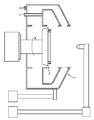
세정공정에는 크게 케미칼 단계, 린스단계, 그리고 건조단계로 이루어진다. 케미칼단계에는 황산과 같은 강산의 케미칼을 기판 상에 공급하고, 린스단계에는 기판 상에 잔류되는 케미칼을 탈이온수로 제거한다. 도1은 세정공정에서 사용되는 일반적인 기판처리장치를 보여주는 일 예로써, 하우징(2) 내에는 기판을 처리하는 공간에 제공되고, 스핀헤드(4)는 하우징(2)의 내부공간에 위치된다. 그러나 케미칼 단계에서 발생되는 퓸(Fume)은 하우징(2)의 내측면에 부착되어 하우징(2)을 오염시키고, 이는 하우징(2) 내에서 파티클로 작용한다. 이로 인해 주기적인 하우징(2)의 내측면의 세정이 요구되나, 케미칼의 제거가 용이하지 않다. 또한 하우징(2)에 사용되는 세정액의 종류에 따라 하우징(2)의 내벽(326,334)은 손상될 수 있다. The cleaning process largely consists of a chemical step, a rinsing step, and a drying step. In the chemical step, a strong acid chemical such as sulfuric acid is supplied onto the substrate, and in the rinsing step, the chemical remaining on the substrate is removed with deionized water. 1 shows an example of a general substrate processing apparatus used in the cleaning process. In the housing 2, a space for processing a substrate is provided, and a
본 발명은 기판을 케미칼로 처리 시 케미칼이 하우징의 내측면에 부착되는 것을 예방할 수 있는 장치 및 방법을 제공하고자 한다.The present invention seeks to provide an apparatus and a method that can prevent chemicals from adhering to the inner surface of a housing when the substrate is treated with chemicals.
본 발명의 실시예는 기판을 약액 처리하는 장치 및 방법을 제공한다. 기판처리장치는 기판을 지지하며, 회전 가능한 스핀헤드, 상기 스핀헤드를 감싸도록 제공되는 하우징, 상기 스핀헤드에 지지된 기판 상으로 약액을 공급하는 분사유닛, 상기 하우징의 내측면에 세정액을 분사하는 세정부재, 그리고 상기 분사유닛이 기판 상에 약액을 공급하는 동안에 상기 하우징에 세정액이 분사되도록 상기 세정부재를 제어하는 제어기를 포함한다.An embodiment of the present invention provides an apparatus and a method for treating a substrate with a chemical liquid. The substrate processing apparatus includes a rotatable spin head, a housing provided to surround the spin head, a spray unit for supplying a chemical solution onto the substrate supported by the spin head, a spray nozzle for spraying a cleaning liquid onto the inner surface of the housing, And a controller for controlling the cleaning member so that the cleaning liquid is sprayed to the housing while the chemical liquid is supplied onto the substrate.
상기 스핀헤드는 기판을 지지하는 판 형상의 몸체, 상기 몸체의 저면 중앙영역에 결합되는 회전축, 그리고 상기 회전축을 회전시키는 구동기를 포함하고, 상기 세정부재는 상기 몸체의 아래에 위치되는 프레임에 설치될 수 있다. 상기 세정부재는 세정액이 상기 몸체로부터 되튀어 상기 하우징의 내측면에 제공되도록 상기 몸체의 저면 가장자리영역을 향하는 토출구를 가지는 세정노즐을 포함할 수 있다. 상기 몸체의 가장자리영역에는 핀홀이 형성되고, 상기 스핀헤드는 상기 핀홀에 삽입되고, 기판의 외측부를 지지하는 척핀을 더 포함하고, 상기 세정부재는 상기 핀홀과 대향되게 위치될 수 있다. 상기 세정부재는 상기 토출구를 통해 세정액을 분사하는 세정노즐을 포함하되, 상기 세정노즐은 복수 개로 제공되며, 상기 세정노즐들은 서로 조합되어 링 형상을 가지도록 상기 프레임에 배열될 수 있다.The spin head includes a plate-shaped body for supporting a substrate, a rotating shaft coupled to a central area of the bottom of the body, and a driver for rotating the rotating shaft, wherein the cleaning member is installed in a frame positioned below the body . The cleaning member may include a cleaning nozzle having a discharge port toward the bottom edge region of the body so that the cleaning liquid is repelled from the body and provided on the inner surface of the housing. A pinhole is formed in an edge region of the body, the spin head further includes a chuck pin inserted in the pinhole and supporting an outer side of the substrate, and the cleaning member can be positioned to face the pinhole. The cleaning member may include a cleaning nozzle for spraying a cleaning liquid through the discharge port. The cleaning nozzles may be provided in plural, and the cleaning nozzles may be arranged in the frame to have a ring shape in combination with each other.
스핀헤드에 지지된 기판에 약액을 공급하여 상기 기판을 처리하는 방법에 있어서, 상기 기판 상으로 약액을 공급하는 동안, 세정부재는 상기 스핀헤드를 감싸는 하우징의 내측면에 세정액을 분사한다. A method of processing a substrate by supplying a chemical solution to a substrate supported on a spin head, wherein a cleaning member injects a cleaning solution onto the inner surface of the housing surrounding the spin head, while supplying the chemical solution onto the substrate.
상기 기판 상에 약액이 공급하기 전부터, 상기 세정부재는 상기 하우징의 내측면에 세정액을 분사하여 상기 하우징의 내측면에 액막을 형성할 수 있다. 상기 기판 상에 약액의 공급이 종료된 후에 계속적으로, 상기 세정부재는 상기 하우징의 내측면에 세정액을 분사하여 상기 하우징의 내측면을 세정할 수 있다. 상기 세정부재는 세정액이 상기 스핀헤드로부터 되튀어 상기 하우징의 내측면에 제공되도록 상기 몸체의 저면 가장자리영역에 세정액을 분사할 수 있다. 상기 약액은 산 또는 염기의 성질을 가지는 케미칼로 제공될 수 있다.Before the chemical liquid is supplied onto the substrate, the cleaning member may spray a cleaning liquid on the inner surface of the housing to form a liquid film on the inner surface of the housing. After the supply of the chemical liquid onto the substrate is completed, the cleaning member can continuously clean the inner surface of the housing by spraying the cleaning liquid on the inner surface of the housing. The cleaning member may spray the cleaning liquid to the bottom edge region of the body so that the cleaning liquid is repelled from the spin head and provided on the inner surface of the housing. The chemical liquid may be provided as a chemical having acid or base properties.
본 발명의 실시예에 의하면, 기판을 케미칼로 처리하는 동안 하우징의 내벽(326,334)에 세정액을 분사하므로, 케미칼이 하우징의 내벽(326,334)에 부착되는 것을 최소화할 수 있다.According to an embodiment of the present invention, the cleaning liquid is sprayed to the
또한 세정부재는 세정액을 스핀헤드로 분사하고, 분사된 세정액이 스핀헤드로부터 되튀고 하우징으로 제공하므로, 스핀헤드 및 하우징을 동시에 세정할 수 있다.Further, the cleaning member can simultaneously clean the spin head and the housing, since the cleaning liquid is sprayed to the spin head, and the sprayed cleaning liquid springs back from the spin head and supplies to the housing.
도1은 일반적인 기판처리장치를 보여주는 단면도이다.
도2는 본 발명의 제1실시예에 따른 기판처리설비를 보여주는 평면도이다.
도3은 도2의 기판처리장치를 보여주는 단면도이다.
도4는 도3의 'A' 영역을 확대해 보여주는 단면도이다.
도5는 도3의 세정부재를 보여주는 평면도이다.
도6은 도3의 세정부재의 제2실시예를 보여주는 단면도이다.
도7은 도3의 세정부재의 제3실시예를 보여주는 단면도이다.
도8은 도3의 세정부재의 제4실시예를 보여주는 단면도이다.
도9는 도3의 세정부재의 제5실시예를 보여주는 단면도이다.
도10은 도3의 세정부재의 제6실시예를 보여주는 단면도이다.
도11은 도3의 기판처리장치의 다른 실시예를 보여주는 단면도이다.1 is a sectional view showing a general substrate processing apparatus.
2 is a plan view showing a substrate processing apparatus according to a first embodiment of the present invention.
3 is a cross-sectional view showing the substrate processing apparatus of FIG.
4 is an enlarged cross-sectional view of the 'A' region of FIG.
Figure 5 is a top view showing the cleaning member of Figure 3;
FIG. 6 is a cross-sectional view showing a second embodiment of the cleaning member of FIG. 3;
FIG. 7 is a cross-sectional view showing a third embodiment of the cleaning member of FIG. 3;
FIG. 8 is a cross-sectional view showing a fourth embodiment of the cleaning member of FIG. 3;
FIG. 9 is a cross-sectional view showing a fifth embodiment of the cleaning member of FIG. 3;
10 is a cross-sectional view showing a sixth embodiment of the cleaning member of FIG. 3;
11 is a cross-sectional view showing another embodiment of the substrate processing apparatus of FIG.
본 발명의 실시예는 여러 가지 형태로 변형될 수 있으며, 본 발명의 범위가 아래에서 서술하는 실시예로 인해 한정되어지는 것으로 해석되어서는 안된다. 본 실시예는 당업계에서 평균적인 지식을 가진 자에게 본 발명을 보다 완전하게 설명하기 위해서 제공되는 것이다. 따라서 도면에서의 구성 요소의 형상 등은 보다 명확한 설명을 강조하기 위해서 과장된 것이다.The embodiments of the present invention can be modified into various forms and the scope of the present invention should not be interpreted as being limited by the embodiments described below. The present embodiments are provided to enable those skilled in the art to more fully understand the present invention. Accordingly, the shapes of the components and the like in the drawings are exaggerated in order to emphasize a clearer description.
본 실시예에는 세정액 및 건조액을 사용하여 기판을 세정 처리하는 공정을 예로 들어 설명한다. 그러나 본 실시예는 세정공정에 한정되지 않으며, 현상액 및 식각액 등 다양한 종류의 액에 적용 가능하다. .In this embodiment, a process of cleaning the substrate by using a cleaning liquid and a drying liquid will be described as an example. However, the present embodiment is not limited to the cleaning process, and can be applied to various kinds of liquids such as a developing solution and an etching solution. .
이하, 도2 내지 도11을 참조하여 본 발명의 일 예를 상세히 설명한다.Hereinafter, an example of the present invention will be described in detail with reference to FIGS. 2 to 11. FIG.
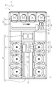
도2는 본 발명의 실시예에 따른 기판처리설비를 보여주는 평면도이다. 도3을 참조하면, 기판처리설비(1)는 인덱스모듈(10)과 공정처리모듈(20)을 가진다. 인덱스모듈(10)은 로드포트(120) 및 이송프레임(140)을 가진다. 로드포트(120), 이송프레임(140), 그리고 공정처리모듈(20)은 순차적으로 일렬로 배열된다. 이하, 로드포트(120), 이송프레임(140), 그리고 공정처리모듈(20)이 배열된 방향을 제1방향(12)이라 하고, 상부에서 바라볼 때, 제1방향(12)과 수직한 방향을 제2방향(14)이라 하며, 제1방향(12)과 제2방향(14)을 포함한 평면에 수직인 방향을 제3방향(16)이라 칭한다. 2 is a plan view showing a substrate processing apparatus according to an embodiment of the present invention. Referring to FIG. 3, the
로드포트(140)에는 기판(W)이 수납된 캐리어(130)가 안착된다. 로드포트(120)는 복수 개가 제공되며 이들은 제2방향(14)을 따라 일렬로 배치된다. 로드포트(120)의 개수는 공정처리모듈(20)의 공정효율 및 풋 프린트조건 등에 따라 증가하거나 감소할 수도 있다. 캐리어(130)에는 기판(W)들을 지면에 대해 수평하게 배치한 상태로 수납하기 위한 다수의 슬롯(미도시)이 형성된다. 캐리어(130)로는 전면개방일체형포드(Front Opening Unifed Pod;FOUP)가 사용될 수 있다. The carrier 130 in which the substrate W is accommodated is seated in the
공정처리모듈(20)은 버퍼유닛(220), 이송챔버(240), 그리고 공정챔버(260)를 가진다. 이송챔버(240)는 그 길이 방향이 제 1 방향(12)과 평행하게 배치된다. 이송챔버(240)의 양측에는 각각 공정챔버들(260)이 배치된다. 이송챔버(240)의 일측 및 타측에서 공정챔버들(260)은 이송챔버(240)를 기준으로 대칭되도록 제공된다. 이송챔버(240)의 일측에는 복수 개의 공정챔버들(260)이 제공된다. 공정챔버(260)들 중 일부는 이송챔버(240)의 길이 방향을 따라 배치된다. 또한, 공정챔버(260)들 중 일부는 서로 적층되게 배치된다. 즉, 이송챔버(240)의 일측에는 공정챔버(260)들이 A X B의 배열로 배치될 수 있다. 여기서 A는 제1방향(12)을 따라 일렬로 제공된 공정챔버(260)의 수이고, B는 제3방향(16)을 따라 일렬로 제공된 공정챔버(260)의 수이다. 이송챔버(240)의 일측에 공정챔버(260)가 4개 또는 6개 제공되는 경우, 공정챔버(260)들은 2 X 2 또는 3 X 2의 배열로 배치될 수 있다. 공정챔버(260)의 개수는 증가하거나 감소할 수도 있다. 상술한 바와 달리, 공정챔버(260)는 이송챔버(240)의 일측에만 제공될 수 있다. 또한, 공정챔버(260)는 이송챔버(240)의 일측 및 양측에 단층으로 제공될 수 있다.The
버퍼유닛(220)은 이송프레임(140)과 이송챔버(240) 사이에 배치된다. 버퍼 유닛(220)은 이송챔버(240)와 이송프레임(140) 간에 기판(W)이 반송되기 전에 기판(W)이 머무르는 공간을 제공한다. 버퍼유닛(220)의 내부에는 기판(W)이 놓이는 슬롯(미도시)이 제공된다. 슬롯(미도시)들은 서로 간에 제3방향(16)을 따라 이격되도록 복수 개가 제공된다. 버퍼유닛(220)은 이송프레임(140)과 마주보는 면 및 이송챔버(240)와 마주보는 면이 개방된다. The
이송프레임(140)은 로드포트(120)에 안착된 캐리어(130)와 버퍼유닛(220) 간에 기판(W)을 반송한다. 이송프레임(140)에는 인덱스레일(142)과 인덱스로봇(144)이 제공된다. 인덱스레일(142)은 그 길이 방향이 제2방향(14)과 나란하게 제공된다. 인덱스로봇(144)은 인덱스레일(142) 상에 설치되며, 인덱스레일(142)을 따라 제2방향(14)으로 직선 이동된다. 인덱스로봇(144)은 베이스(144a), 몸체(144b), 그리고 인덱스암(144c)을 가진다. 베이스(144a)는 인덱스레일(142)을 따라 이동 가능하도록 설치된다. 몸체(144b)는 베이스(144a)에 결합된다. 몸체(144b)는 베이스(144a) 상에서 제3방향(16)을 따라 이동 가능하도록 제공된다. 또한, 몸체(144b)는 베이스(144a) 상에서 회전 가능하도록 제공된다. 인덱스암(144c)은 몸체(144b)에 결합되고, 몸체(144b)에 대해 전진 및 후진 이동 가능하도록 제공된다. 인덱스암(144c)은 복수 개 제공되어 각각 개별 구동되도록 제공된다. 인덱스암(144c)들은 제3방향(16)을 따라 서로 이격된 상태로 적층되게 배치된다. 인덱스암(144c)들 중 일부는 공정처리모듈(20)에서 캐리어(130)로 기판(W)을 반송할 때 사용되고, 이의 다른 일부는 캐리어(130)에서 공정처리모듈(20)로 기판(W)을 반송할 때 사용될 수 있다. 이는 인덱스로봇(144)이 기판(W)을 반입 및 반출하는 과정에서 공정 처리 전의 기판(W)으로부터 발생된 파티클이 공정 처리 후의 기판(W)에 부착되는 것을 방지할 수 있다. The
이송챔버(240)는 버퍼유닛(220)과 공정챔버(260) 간에, 그리고 공정챔버(260)들 간에 기판(W)을 반송한다. 이송챔버(240)에는 가이드레일(242)과 메인로봇(244)이 제공된다. 가이드레일(242)은 그 길이 방향이 제1방향(12)과 나란하도록 배치된다. 메인로봇(244)은 가이드레일(242) 상에 설치되고, 가이드레일(242) 상에서 제1방향(12)을 따라 직선 이동된다. 메인로봇(244)은 베이스(244a), 몸체(244b), 그리고 메인암(244c)을 가진다. 베이스(244a)는 가이드레일(242)을 따라 이동 가능하도록 설치된다. 몸체(244b)는 베이스(244a)에 결합된다. 몸체(244b)는 베이스(244a) 상에서 제3방향(16)을 따라 이동 가능하도록 제공된다. 또한, 몸체(244b)는 베이스(244a) 상에서 회전 가능하도록 제공된다. 메인암(244c)은 몸체(244b)에 결합되고, 이는 몸체(244b)에 대해 전진 및 후진 이동 가능하도록 제공된다. 메인암(244c)은 복수 개 제공되어 각각 개별 구동되도록 제공된다. 메인암(244c)들은 제3방향(16)을 따라 서로 이격된 상태로 적층되게 배치된다. The
공정챔버(260)는 기판(W)에 대해 세정 공정을 수행하는 기판처리장치(300)가 제공된다. 기판처리장치(300)는 수행하는 세정 공정의 종류에 따라 상이한 구조를 가질 수 있다. 이와 달리 각각의 공정처리챔버(260) 내의 기판처리장치(300)는 동일한 구조를 가질 수 있다. 선택적으로 공정챔버(260)들은 복수 개의 그룹으로 구분되어, 동일한 그룹에 속하는 공정챔버(260) 내에 기판처리장치(300)들은 서로 동일하고, 서로 상이한 그룹에 속하는 공정챔버(260) 내에 기판처리장치(300)의 구조는 서로 상이하게 제공될 수 있다.The
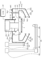
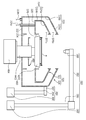
도3은 도2의 기판처리장치를 보여주는 단면도이다. 도3을 참조하면, 기판처리장치(300)는 하우징(320), 승강유닛(360), 분사유닛(380), 스핀헤드(400), 세정부재(480) 그리고 제어기를 포함한다. 3 is a cross-sectional view showing the substrate processing apparatus of FIG. 3, the substrate processing apparatus 300 includes a
하우징(320)은 내부에 기판이 처리되는 공간을 제공한다. 하우징은 그 내부에 위치된 스핀헤드를 감싸는 원통의 형상으로 제공된다. 하우징(320)은 내부회수통(322) 및 외부회수통(328)을 가진다. 각각의 회수통(322,328)은 공정에 사용된 약액들 중 서로 상이한 약액을 회수한다. 내부회수통(322)은 스핀헤드를 감싸는 환형의 링 형상으로 제공되고, 외부회수통(328)은 내부회수통(328)을 감싸는 환형의 링 형상으로 제공된다. The
각각의 회수통(322,328)은 링 형상의 외벽(324,330), 바닥벽(325,332), 그리고 내벽(326,334)을 포함한다. 외벽(324,330)은 스핀헤드로부터 멀어지는 방향으로 하향경사진 경사벽과 이의 하단으로부터 아래방향으로 수직하게 연장되는 수직벽을 가진다. 바닥벽(325,332)은 수직벽의 하단으로부터 스핀헤드를 향하는 방향으로 수평하게 연장된다. 내벽(326,334)은 바닥벽(325,332)의 끝단으로부터 위로 수직하게 연장된다. 내벽(326,334)은 경사벽의 상단과 상하방향으로 대향되게 위치된다. 내벽(326,334)의 상단과 경사벽의 상단은 서로 이격되게 위치된다. 내부회수통의 외부회수통의 내벽(326,334)과 외벽(324,330) 사이의 이격된 공간에 위치된다. Each of the
내부회수통(322)의 내측공간(322a) 및 내부회수통(322)과 외부회수통(328)의 사이공간(328a)은 각각 내부회수통(322) 및 외부회수통(328)으로 약액이 유입되는 유입구로서 기능한다. 일 예에 의하면, 각각의 유입구는 서로 상이한 높이에 위치될 수 있다. 각각의 회수통(322,328)의 저면 아래에는 회수라인(322b,328b)이 연결된다. 각각의 회수통(322,328)에 유입된 약액들은 회수라인(322b,328b)을 통해 외부의 약액재생시스템(미도시)으로 제공되어 재사용될 수 있다.The
승강유닛(360)은 하우징(320)을 상하 방향으로 직선이동시킨다. 하우징(320)이 상하로 이동됨에 따라 스핀헤드(400)에 대한 하우징(320)의 상대 높이가 변경된다. 승강유닛(360)은 브라켓(362), 이동축(364), 그리고 구동기(366)를 가진다. 브라켓(362)은 하우징(320)의 외벽(324,330)에 고정설치되고, 브라켓(362)에는 구동기(366)에 의해 상하 방향으로 이동되는 이동축(364)이 고정결합된다. 기판(W)이 스핀헤드(400)에 놓이거나, 스핀헤드(400)로부터 들어올려 질 때 스핀헤드(400)가 하우징(320)의 상부로 돌출되도록 하우징(320)은 하강된다. 또한, 공정이 진행될 시에는 기판(W)에 공급된 약액의 종류에 따라 약액이 기설정된 회수통(360)으로 유입될 수 있도록 하우징(320)의 높이가 조절한다. 선택적으로, 승강유닛(360)은 스핀헤드(400)를 상하 방향으로 이동시킬 수 있다.The
분사유닛(380)은 기판(W) 상으로 복수의 약액들을 분사한다. 분사유닛(380)은 복수 개로 제공될 수 있다. 각각의 분사유닛(380)은 회전축(386), 지지대(382), 그리고 약액노즐(384)을 포함한다. 회전축(386)은 하우징(320)의 일측에 배치된다. 회전축(386)은 그 길이방향이 상하방향으로 제공되는 로드 형상을 가진다. 회전축(386)은 구동부재(388)에 의해 회전 및 승강운동이 가능하다. 이와 달리 회전축(386)은 구동부재(388)에 의해 수평방향으로 직선이동 및 승강운동할 수 있다. 지지대(382)는 약액노즐(384)을 지지한다. 지지대(382)는 회전축(386)에 결합되고, 끝단 저면에는 약액노즐(384)이 고정 결합된다. 약액노즐(384)은 회전축(386)의 회전에 의해 스윙이동될 수 있다. 일 예에 의하면, 약액은 산 또는 염기의 성질을 가지는 케미칼로 제공될 수 있다. 케미칼은 황산(H2SO4), 불산(HF), 질산(HNO3), 또는 암모늄(Ammonium)을 포함할 수 있다.The
스핀헤드(400)는 공정 진행 중 기판(W)을 지지하고 기판(W)을 회전시킨다. 도4는 도3의 'A' 영역을 확대해 보여주는 단면도이다. 도4를 참조하면, 스핀헤드(400)는 몸체(420), 지지핀(402), 척핀(404), 회전축(440), 그리고 구동부재(460)를 포함한다. The
몸체(420)는 대체로 원형의 판 형상으로 제공된다. 몸체(420)의 외측면은 아래로 갈수록 경사지게 제공된다. 일 예에 의하면, 몸체(420)의 외측면은 아래로 갈수록 그 중심축과 가까워지도록 제공될 수 있다. 몸체(420)의 상면에는 복수의 나사홈(미도시)들이 형성된다. 또한 몸체(420)의 상면 가장자리에는 복수의 핀홀(422)들이 형성된다. 핀홀(422)은 몸체(420)의 중심에서 나사홈(미도시)보다 멀리 떨어지게 형성된다. 각각의 핀홀(422)은 서로 조합되어 환형의 링 형상을 가지도록 배열된다. 각각의 핀홀(422)은 서로 일정간격으로 이격되게 위치된다. 상부에서 바라볼 때 각각의 핀홀(422)은 그 길이방향이 몸체(420)의 반경방향을 향하도록 제공된다. 몸체(420)의 저면 가장자리에는 복수의 제1배출홀(424)들이 형성된다. 제1배출홀(424)들은 핀홀(422)과 동일한 개수로 제공된다. 각각의 제1배출홀(424)은 핀홀(422)과 상하방향으로 대향되게 형성된다. 각각의 제1배출홀(424)은 서로 조합되어 환형의 링 형상을 가지도록 배열된다. 하나의 제1배출홀(424)은 몸체(420)의 내부공간을 통해 하나의 핀홀(422)과 통하도록 제공된다. 또한 몸체(420)의 외측면에는 복수의 제2배출홀(426)들이 형성된다. 제2배출홀(426)들은 핀홀(422)과 동일한 개수로 제공된다. 각각의 제2배출홀(426)은 서로 조합되어 환형의 링 형상을 가지도록 배열된다. 하나의 제2배출홀(426)은 몸체(420)의 내부공간을 통해 하나의 핀홀(422)과 통하도록 제공된다.The
지지핀(402)은 기판의 저면을 지지하도록 제공된다. 지지핀(402)은 복수 개로 제공되며, 각각의 나사홈(미도시)에 고정결합된다. 지지핀(402)은 나사홈(미도시)으로부터 위로 돌출되게 제공된다. The support pins 402 are provided to support the bottom surface of the substrate. A plurality of support pins 402 are provided and fixedly coupled to respective screw grooves (not shown). The
척핀(404)은 스핀헤드(400)가 회전될 때 기판이 정 위치에서 측 방향으로 이탈되지 않도록 기판의 외측부를 지지한다. 척핀(404)은 복수 개 제공되며, 각각의 핀홀(422)에 삽입된다. 척핀(404)은 몸체(420)의 상면으로부터 상부로 돌출되도록 제공된다. 척핀(404)은 핀홀(422)의 길이방향을 따라 대기위치와 지지위치 간에 이동 가능하다. 척핀(404)은 몸체(420) 내에 제공된 척핀(404)이동유닛을 통해 대기위치와 지지위치로 이동된다. 여기서 대기위치는 척핀(404)이 기판을 지지하지 않는 위치이고, 지지위치는 척핀(404)이 기판을 지지하는 위치이다. 대기위치는 지지위치에 비해 몸체(420)의 중심으로부터 멀리 떨어진 위치이다. 일 예에 의하면, 기판이 스핀헤드(400)에 로딩 또는 언로딩 시 척핀(404)은 대기위치에 위치되고, 기판에 대해 공정 수행 시 척핀(404)은 지지위치에 위치된다. The
다시 도3을 참조하면, 회전축(440)은 몸체(420)의 저면과 고정결합된다. 회전축(440)은 그 길이방향이 상하방향을 향하도록 제공된다. 회전축(440)은 구동부재(460)에 의해 중심축을 중심으로 회전 가능하도록 제공된다. Referring again to FIG. 3, the
구동부재(460)는 몸체(420)가 회전되도록 회전축(440)에 구동력을 제공한다. 구동부재(460)는 프레임(462) 및 구동기(464)를 포함한다. 프레임(462)은 내부에 공간이 제공되는 통 형상으로 제공된다. 상부에서 바라볼 때 프레임(462)은 몸체(420)에 비해 작은 원 형상으로 제공된다. 프레임(462)의 상면 중앙에는 회전축(440)이 삽입되는 개구가 형성된다. 프레임(462)의 상부영역은 외부회수통의 저면을 관통하도록 제공된다. 구동기(464)는 프레임(462) 내에서 회전축(440)에 구동력을 제공한다. 예컨대, 구동기(464)는 모터일 수 있다.The driving
세정부재(480)는 세정액을 분사하여 스핀헤드(400) 및 하우징의 내측면을 세정한다. 세정부재(480)는 스핀헤드(400)에 세정액을 분사하고, 분사된 세정액은 스핀헤드(400)로부터 되튀어 하우징(320)의 내측면에 제공된다. 예컨대, 세정액은 순수일 수 있다. 도5는 도3의 세정부재를 보여주는 평면도이다. 도5를 참조하면, 세정부재(480)는 지지로드(482) 및 세정노즐(484)을 포함한다. The cleaning
지지로드(482)는 세정노즐(484)을 지지한다. 지지로드(482)는 복수 개로 제공되며, 각각은 하나의 세정노즐(484)을 지지한다. 각각의 지지로드(482)는 프레임(462)의 상면 가장자리에 설치된다. 각각의 지지로드(482)는 서로 조합되어 환형의 링 형상을 가지도록 배열된다. 지지로드(482)는 세정노즐(484)이 몸체(420)의 저면 가장자리에 대향되게 위치되도록 세정노즐(484)과 결합된다. 지지로드(482)는 그 길이방향이 대체로 몸체(420)의 반경방향을 향하도록 제공된다. 지지로드(482)는 수직부 및 수평부를 가진다. 수직부는 그 길이방향이 수직방향을 향하는 로드 형상으로 제공되며, 프레임(462)의 상면 가장자리에 고정 결합된다. 수평부는 그 길이방향이 몸체(420)의 반경방향과 평행한 방향을 향하는 로드 형상으로 제공된다. 수평부는 그 길이가 수직부에 비해 길게 제공된다. 수평부의 일단은 수직부의 상단에 고정결합되고, 타단은 세정노즐(484)과 결합된다. 일 예에 의하면, 수평부의 타단은 척핀(404)이 회전되는 경로와 대향되도록 위치될 수 있다. The support rod 482 supports the cleaning
세정노즐(484)은 지지로드(482)에 고정결합된다. 세정노즐(484)의 토출구는 저면 가장자리를 향하도록 제공된다.The cleaning
제어기(500)는 세정노즐(484)의 동작을 제어한다. 제어기(500)는 기판 상에 케미칼을 공급하는 동안 세정노즐(484)로부터 세정액이 분사되도록 세정노즐(484)을 제어한다. 또한 제어기(500)는 기판 상에 케미칼을 공급하기 전부터 세정노즐(484)로부터 세정액이 분사되도록 세정노즐(484)을 제어할 수 있다. 또한 제어기(500)는 기판 상에 케미칼이 공급된 후에 계속적으로 세정노즐(484)로부터 세정액이 분사되도록 세정노즐(484)을 제어할 수 있다.The
다음은 상술한 기판처리장치(300)를 이용하여 기판(W)을 처리하는 방법에 대해 설명한다. 스핀헤드(400)에 기판이 로딩되면, 척핀(404)은 대기위치에서 지지위치로 이동된다. 기판(W)은 스핀헤드(400)에 의해 회전되고, 세정노즐(484)은 스핀헤드(400)의 저면 가장자리로 세정액을 분사한다. 세정노즐(484)로부터 분사된 세정액은 스핀헤드(400)로부터 되튀어 하우징(320)의 내측면으로 제공된다. 스핀헤드(400) 및 하우징(320)의 내측면에 세정액으로 인해 액막이 형성되면, 약액노즐은 기판(W) 상으로 케미칼을 공급한다. 이때 세정노즐(484)은 계속적으로 세정액을 분사한다. 기판(W)의 케미칼 공정이 완료되면, 케미칼의 공급을 종료한다. 세정노즐(484)은 케미칼 공정이 완료된 이후에도, 세정액을 분사하여 스핀헤드(400) 및 하우징(320)에 잔류된 케미칼 및 이로부터 발생되는 퓸을 세정할 수 있다.Next, a method of processing the substrate W using the above-described substrate processing apparatus 300 will be described. When the substrate is loaded on the
상술한 실시예에 의하면, 세정노즐(484)은 척핀(404)이 회전되는 경로와 대향되게 위치된다. 세정노즐(484)로부터 분사된 세정액의 일부는 스핀헤드(400)에 형성된 제1배출홀(424)로 유입된다. 이로 인해 핀홀(422)을 통해 몸체(420) 내에 유입된 케미칼 및 이로부터 발생된 퓸은 세정되고, 제1배출홀(424) 또는 제2배출홀(426)을 통해 배출될 수 있다.According to the above-described embodiment, the cleaning
또한 세정노즐(484)은 기판(W)의 케미칼 공정이 진행되기 전부터 세정액을 분사하므로, 세정액으로 인한 액막을 스핀헤드(400) 및 하우징(320)에 형성하여 케미칼이 스핀헤드(400) 및 하우징(320)에 고착되는 것을 방지할 수 있다. Since the
상술한 바와 달리, 세정부재(480)는 아래와 같이 다양하게 제공될 수 있다.Unlike the above, the cleaning
세정부재(480)의 제2실시예에 의하면, 도6과 같이 세정노즐(484)의 토출구는 몸체(420)의 중심축과 멀어질수록 상향 경사진 방향을 향하도록 제공될 수 있다. According to the second embodiment of the cleaning
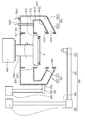
세정부재(480)의 제3실시예에 의하면, 도7과 같이 세정부재(480)는 하우징(320)에 설치될 수 있다. 세정부재(480)의 세정노즐(484)은 각각의 회수통(322,328)의 경사벽(324a,330a)의 내측면에 설치될 수 있다. 세정노즐(484)은 각각의 회수통(322,328)의 경사벽(324a,330a)에서 토출구가 각각의 회수통(322,328)의 수직벽(324b,330b)의 내측면을 향하도록 제공될 수 있다.According to the third embodiment of the cleaning
세정부재(480)의 제4실시예에 의하면, 도8과 같이 스핀헤드(400)는 고정축을 더 포함할 수 있다. 고정축은 회전축(440)을 감싸는 원통 형상으로 제공되며, 회전축(440)과 달리 회전되지 않도록 제공될 수 있다. 세정부재(480)는 고정축의 외측면에 설치될 수 있다. 세정부재(480)의 지지로드(482)는 그 길이방향이 몸체(420)의 외측방향을 향하도록 고정축의 외측면에 설치될 수 있다. 지지로드(482)의 끝단에는 세정노즐(484)이 설치되고, 토출구가 몸체(420)의 저면 가장자리를 향하도록 제공될 수 있다.According to the fourth embodiment of the cleaning
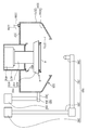
세정부재(480)의 제5실시예에 의하면, 도9와 같이 세정부재(480)의 세정노즐(484) 및 지지로드(482)는 각각의 회수통(322,328)의 상단에 설치될 수 있다. 지지로드(482)는 외부회수통(328)의 경사벽(330a)의 상단 및 내부회수통(322)의 경사벽(324a)의 상단에 각각에 설치될 수 있다. 지지로드(482)의 길이방향은 하우징(320)의 내측방향을 향하도록 제공될 수 있다. 세정노즐(484)은 각각의 지지로드(482)의 끝단에 설치되어 하우징(320)의 내측면으로 세정액을 분사할 수 있다.According to the fifth embodiment of the cleaning
세정부재(480)의 제6실시예에 의하면, 도10과 같이 세정부재(480)는 수직로드를 더 포함할 수 있다. 세정부재(480)의 지지로드(482)는 외부회수통(328)의 상단에 설치되고, 그 길이방향은 하우징(320)의 내측방향을 향하도록 제공될 수 있다. 수직로드는 지지로드(482)의 저면 끝단에 결합될 수 있다. 수직로드는 그 길이방향이 수직방향을 향하도록 제공되고, 그 하단에는 세정노즐(484)이 설치될 수 있다. 수직로드는 구동기(464)(미도시)에 의해 그 길이가 조절되도록 제공될 수 있다. 수직로드의 길이가 조절됨에 따라, 세정노즐(484)은 외부회수통의 내측면에 대응되는 위치 또는 내부회수통의 내측면에 대응되는 위치로 이동될 수 있다.According to the sixth embodiment of the cleaning
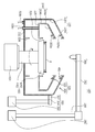
또한 기판처리장치(300)의 다른 실시예에 의하면, 도11과 같이 하우징(320)은 하나의 회수통(328)으로 제공될 수 있다.According to another embodiment of the substrate processing apparatus 300, as shown in FIG. 11, the
320: 하우징 380: 분사유닛
400: 스핀헤드 480: 세정부재
500: 제어기320: housing 380: injection unit
400: spin head 480: cleaning member
500: controller
Claims (2)
상기 스핀헤드를 감싸도록 제공되는 하우징과;
상기 스핀헤드에 지지된 기판 상으로 약액을 공급하는 분사유닛과;
상기 하우징의 내측면에 세정액을 분사하는 세정부재와;
상기 분사유닛이 기판 상에 약액을 공급하는 동안에 상기 하우징에 세정액이 분사되도록 상기 세정부재를 제어하는 제어기를 포함하는 기판처리장치.A spin head for supporting the substrate, the spin head being rotatable;
A housing provided to surround the spin head;
A spray unit for spraying a chemical solution onto the substrate supported by the spin head;
A cleaning member for spraying a cleaning liquid onto the inner surface of the housing;
And a controller for controlling the cleaning member so that the cleaning liquid is sprayed to the housing while the injection unit supplies the chemical liquid onto the substrate.
상기 스핀헤드는,
기판을 지지하는 판 형상의 몸체와;
상기 몸체의 저면 중앙영역에 결합되는 회전축과;
상기 회전축을 회전시키는 구동기를 포함하고,
상기 세정부재는 상기 몸체의 아래에 위치되는 프레임에 설치되는 기판처리장치.The method according to claim 1,
The spin-
A plate-shaped body for supporting the substrate;
A rotating shaft coupled to a bottom central region of the body;
And a driver for rotating the rotation shaft,
Wherein the cleaning member is installed in a frame located under the body.
Priority Applications (1)
| Application Number | Priority Date | Filing Date | Title |
|---|---|---|---|
| KR1020130015194A KR102121239B1 (en) | 2013-02-13 | 2013-02-13 | Apparatus and method for treating substrate |
Applications Claiming Priority (1)
| Application Number | Priority Date | Filing Date | Title |
|---|---|---|---|
| KR1020130015194A KR102121239B1 (en) | 2013-02-13 | 2013-02-13 | Apparatus and method for treating substrate |
Publications (2)
| Publication Number | Publication Date |
|---|---|
| KR20140101947A true KR20140101947A (en) | 2014-08-21 |
| KR102121239B1 KR102121239B1 (en) | 2020-06-10 |
Family
ID=51747010
Family Applications (1)
| Application Number | Title | Priority Date | Filing Date |
|---|---|---|---|
| KR1020130015194A KR102121239B1 (en) | 2013-02-13 | 2013-02-13 | Apparatus and method for treating substrate |
Country Status (1)
| Country | Link |
|---|---|
| KR (1) | KR102121239B1 (en) |
Cited By (2)
| Publication number | Priority date | Publication date | Assignee | Title |
|---|---|---|---|---|
| KR20160041160A (en) | 2014-10-06 | 2016-04-18 | 세메스 주식회사 | Unit for supplying chemical, Apparatus for treating substrate with the unit, and Method for replaced heater |
| US10022746B2 (en) | 2014-09-30 | 2018-07-17 | Semes Co., Ltd. | Apparatus and method for treating a substrate |
Citations (5)
| Publication number | Priority date | Publication date | Assignee | Title |
|---|---|---|---|---|
| KR20020000717A (en) * | 2000-06-26 | 2002-01-05 | 니시무로 타이죠 | Wafer cleaning method and apparatus |
| KR100525302B1 (en) * | 2005-04-29 | 2005-11-02 | 에스브이에스 주식회사 | Cleaner method of spin cup |
| KR100809591B1 (en) | 2006-09-11 | 2008-03-04 | 세메스 주식회사 | Method for cleaning substrate in single wafer |
| KR20110042014A (en) * | 2009-10-16 | 2011-04-22 | 도쿄엘렉트론가부시키가이샤 | Liquid processing apparatus, liquid processing method and storage medium |
| KR20120110271A (en) * | 2011-03-29 | 2012-10-10 | 주식회사 엘지실트론 | Apparatus for cleaning single wafer |
-
2013
- 2013-02-13 KR KR1020130015194A patent/KR102121239B1/en active IP Right Grant
Patent Citations (5)
| Publication number | Priority date | Publication date | Assignee | Title |
|---|---|---|---|---|
| KR20020000717A (en) * | 2000-06-26 | 2002-01-05 | 니시무로 타이죠 | Wafer cleaning method and apparatus |
| KR100525302B1 (en) * | 2005-04-29 | 2005-11-02 | 에스브이에스 주식회사 | Cleaner method of spin cup |
| KR100809591B1 (en) | 2006-09-11 | 2008-03-04 | 세메스 주식회사 | Method for cleaning substrate in single wafer |
| KR20110042014A (en) * | 2009-10-16 | 2011-04-22 | 도쿄엘렉트론가부시키가이샤 | Liquid processing apparatus, liquid processing method and storage medium |
| KR20120110271A (en) * | 2011-03-29 | 2012-10-10 | 주식회사 엘지실트론 | Apparatus for cleaning single wafer |
Cited By (2)
| Publication number | Priority date | Publication date | Assignee | Title |
|---|---|---|---|---|
| US10022746B2 (en) | 2014-09-30 | 2018-07-17 | Semes Co., Ltd. | Apparatus and method for treating a substrate |
| KR20160041160A (en) | 2014-10-06 | 2016-04-18 | 세메스 주식회사 | Unit for supplying chemical, Apparatus for treating substrate with the unit, and Method for replaced heater |
Also Published As
| Publication number | Publication date |
|---|---|
| KR102121239B1 (en) | 2020-06-10 |
Similar Documents
| Publication | Publication Date | Title |
|---|---|---|
| KR101344921B1 (en) | Apparatus and Method for treating substrate | |
| KR101621482B1 (en) | Apparatus and Method for treating substrate | |
| CN108269752B (en) | Substrate processing apparatus and substrate processing method | |
| KR101909182B1 (en) | Apparatus and method for treating substrate | |
| KR101329319B1 (en) | Nozzle and apparatus for treating a substrate with the nozzle | |
| KR20140112299A (en) | Apparatus for treating substrate | |
| KR102096945B1 (en) | Apparatus and Method for treating substrate | |
| KR101870666B1 (en) | Substrate treating apparatus | |
| KR102121239B1 (en) | Apparatus and method for treating substrate | |
| KR101870664B1 (en) | Apparatus for treating substrate | |
| KR102096944B1 (en) | Apparatus and Method for treating substrate | |
| KR101736853B1 (en) | method and Apparatus for Processing Substrate | |
| KR101330319B1 (en) | Injection unit and Apparatus for treating substrate with the unit | |
| KR102347973B1 (en) | Substrate treating apparatus and substrate treating method | |
| KR20140090588A (en) | Method for treating substrate | |
| KR102410311B1 (en) | method and Apparatus for Processing Substrate | |
| KR20150068761A (en) | Apparatus for treating substrate | |
| KR102193031B1 (en) | Apparatus and Method for treating substrate | |
| KR101355917B1 (en) | Injection unit and Apparatus for treating substrate with the unit | |
| KR20140101475A (en) | Apparatus for treating substrate | |
| KR101910799B1 (en) | Substrate treating apparatus | |
| KR101909480B1 (en) | Substrate treating apparatus | |
| KR102180009B1 (en) | Apparatus and Method for treating substrate | |
| KR102283587B1 (en) | Apparatus and method for processing substrate | |
| KR20160029902A (en) | Chemical nozzle and apparatus for treating substrate |
Legal Events
| Date | Code | Title | Description |
|---|---|---|---|
| A201 | Request for examination | ||
| E902 | Notification of reason for refusal | ||
| E701 | Decision to grant or registration of patent right | ||
| GRNT | Written decision to grant |