KR20140097101A - Plastic bottle - Google Patents
Plastic bottle Download PDFInfo
- Publication number
- KR20140097101A KR20140097101A KR1020147002290A KR20147002290A KR20140097101A KR 20140097101 A KR20140097101 A KR 20140097101A KR 1020147002290 A KR1020147002290 A KR 1020147002290A KR 20147002290 A KR20147002290 A KR 20147002290A KR 20140097101 A KR20140097101 A KR 20140097101A
- Authority
- KR
- South Korea
- Prior art keywords
- rib
- bottle
- ribs
- width
- main body
- Prior art date
Links
Images


Classifications
-
- B—PERFORMING OPERATIONS; TRANSPORTING
- B65—CONVEYING; PACKING; STORING; HANDLING THIN OR FILAMENTARY MATERIAL
- B65D—CONTAINERS FOR STORAGE OR TRANSPORT OF ARTICLES OR MATERIALS, e.g. BAGS, BARRELS, BOTTLES, BOXES, CANS, CARTONS, CRATES, DRUMS, JARS, TANKS, HOPPERS, FORWARDING CONTAINERS; ACCESSORIES, CLOSURES, OR FITTINGS THEREFOR; PACKAGING ELEMENTS; PACKAGES
- B65D1/00—Containers having bodies formed in one piece, e.g. by casting metallic material, by moulding plastics, by blowing vitreous material, by throwing ceramic material, by moulding pulped fibrous material, by deep-drawing operations performed on sheet material
- B65D1/02—Bottles or similar containers with necks or like restricted apertures, designed for pouring contents
- B65D1/0223—Bottles or similar containers with necks or like restricted apertures, designed for pouring contents characterised by shape
-
- B—PERFORMING OPERATIONS; TRANSPORTING
- B65—CONVEYING; PACKING; STORING; HANDLING THIN OR FILAMENTARY MATERIAL
- B65D—CONTAINERS FOR STORAGE OR TRANSPORT OF ARTICLES OR MATERIALS, e.g. BAGS, BARRELS, BOTTLES, BOXES, CANS, CARTONS, CRATES, DRUMS, JARS, TANKS, HOPPERS, FORWARDING CONTAINERS; ACCESSORIES, CLOSURES, OR FITTINGS THEREFOR; PACKAGING ELEMENTS; PACKAGES
- B65D1/00—Containers having bodies formed in one piece, e.g. by casting metallic material, by moulding plastics, by blowing vitreous material, by throwing ceramic material, by moulding pulped fibrous material, by deep-drawing operations performed on sheet material
- B65D1/40—Details of walls
- B65D1/42—Reinforcing or strengthening parts or members
- B65D1/44—Corrugations
-
- B—PERFORMING OPERATIONS; TRANSPORTING
- B65—CONVEYING; PACKING; STORING; HANDLING THIN OR FILAMENTARY MATERIAL
- B65D—CONTAINERS FOR STORAGE OR TRANSPORT OF ARTICLES OR MATERIALS, e.g. BAGS, BARRELS, BOTTLES, BOXES, CANS, CARTONS, CRATES, DRUMS, JARS, TANKS, HOPPERS, FORWARDING CONTAINERS; ACCESSORIES, CLOSURES, OR FITTINGS THEREFOR; PACKAGING ELEMENTS; PACKAGES
- B65D2501/00—Containers having bodies formed in one piece
- B65D2501/0009—Bottles or similar containers with necks or like restricted apertures designed for pouring contents
- B65D2501/0018—Ribs
- B65D2501/0036—Hollow circonferential ribs
Abstract
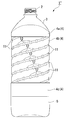
The present invention relates to a thin plastic bottle for filling contents with fluidity, which improves the appearance of the label affixing while suppressing changes in the amount of manchu. A rib 11 formed on the main body portion 4 so as to extend linearly as viewed from the outer side of the bottle and running around the main body portion 4; And the dimples 12 are formed to be wider than the groove width of the ribs 11 in the width direction of the ribs 11 so that the dimples 12 are formed on both sides in the width direction of the ribs 11 And is formed deeper than the groove depth of the rib 11 in the depth direction of the rib 11.
Description
BACKGROUND OF THE
The present application claims priority based on Japanese Patent Application No. 2011-258925 filed on November 28, 2011, the contents of which are incorporated herein by reference.
BACKGROUND ART Conventionally, a bottle made of stretched polyethylene terephthalate called a PET bottle or a thin plastic bottle made of polyethylene or polypropylene (hereinafter, simply referred to as a " bottle ") has been made into a bottle having a fluid content such as shampoo, rinse, It is frequently used as a container for charging. These bottles are subjected to various external forces during storage or transportation of the molded publicly-formed molds, or during transporting, storage and display of the products after charging the contents or after filling, and also in the process of use by the consumer.
As the outer peripheral wall of the bottle body is made thinner, the amount of plastic used is reduced and various effects can be obtained, but the problem remains in terms of strength stiffness. Therefore, a rib of a groove (hereinafter sometimes referred to as " groove-like ") around the main body of the bottle is formed by partially bending the outer peripheral wall of the main body of the bottle, Is suppressed. For example, in
However, in the structure of
SUMMARY OF THE INVENTION The present invention has been made in view of the above circumstances, and it is an object of the present invention to improve the appearance of a thin plastic bottle filled with fluid contents while suppressing changes in the amount of manchu.
A first aspect of the present invention as a solution to the above problem is a thin plastic bottle for filling contents having fluidity, comprising: a normal body portion extending along one direction; and a second body portion extending from the outer side of the body portion, (Hereinafter, referred to as " dimples ") formed on the outer peripheral wall of the main body portion so as to be parallel to the ribs, and a plurality of recesses And each of the recesses is formed to be wider than the groove width of the rib in the width direction of the rib so as to protrude on both sides in the width direction of the rib and to be formed deeper than the groove depth of the rib in the depth direction of the rib .
A second aspect of the present invention is characterized in that, in the first aspect, a plurality of ribs are formed side by side in the extending direction of the main body portion, and the plurality of recesses are formed in each of the plurality of ribs.
In a third aspect of the present invention, in the first or second aspect, the width in the width direction of the ribs and the depth in the depth direction of the ribs in the concave portions are respectively the groove width of the ribs, Is set within a range of 1.2 to 1.8 times the depth of the groove.
A fourth aspect of the present invention is characterized in that, in any one of the first to third aspects, each of the recesses has a circular shape when viewed from the front and a hemispherical concave shape.
A fifth aspect of the present invention is characterized in that, in any one of the first to fourth aspects, the front center of each concave portion is located on the center line of the corresponding rib.
(Effects of the Invention)
According to the first aspect of the present invention, by providing a plurality of concave portions having a wider width and a wider width than the entire width of the straight ribs, each concave portion is reinforced to suppress expansion (expansion) and contraction in the width direction of the rib, The rigidity of the ribs against expansion or contraction can be increased. For this reason, the rigidity of the main body portion against the force from the inside of the bottle when filling the contents having fluidity into the bottle and the force from the outside of the bottle when gripping the bottle is increased, and the stiffness of the main body portion And buckling deformation of the main body portion can be suppressed. Further, by properly restricting the width and depth of each concave portion and maintaining the shape of the rib viewed from the outside of the bottle in a straight line, even when the label is attached to the outer peripheral surface of the main body portion, It is possible to improve the appearance of the bottle at the time of label affixing and to improve the merchantability after suppressing the change in the content of the bottles in comparison with the case of forming the wave rib at the portion.
According to the second aspect of the present invention, it is possible to ensure rigidity over the whole of the extending direction (axial direction) and the circumferential direction of the main body portion.
According to the third aspect of the present invention, the width and depth of each concave portion are suppressed to within a predetermined magnification with respect to the groove width and groove depth of the rib, whereby the shape of the rib viewed from the outside of the bottle is maintained in a straight line, The appearance of the bottle can be improved.
According to the fourth aspect of the present invention, expansion or contraction of the corresponding ribs in the width direction can be effectively suppressed.
According to the fifth aspect of the present invention, it is possible to limit the protrusion of the concave portion biased to one side in the width direction of the corresponding rib.
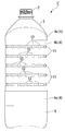
1 is a front view of a plastic bottle according to an embodiment of the present invention.
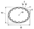
2 is a sectional view taken along the line AA in Fig.
3 is a sectional view taken along line BB of Fig.
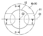
4 is an enlarged view of a portion C in Fig.
5 is a DD sectional view of Fig.
6 is a sectional view taken along line EE of Fig.
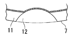
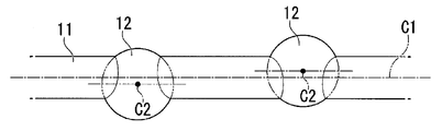
7 is a plan view of the recessed portion in a state in which the outer peripheral wall of the main body portion of the plastic bottle is developed in a plane.
Fig. 8 is a front view corresponding to Fig. 1 showing a modified example of the plastic bottle.
Fig. 9 is a front view corresponding to Fig. 1 showing another modification of the plastic bottle.
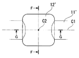
Fig. 10 is an enlarged view corresponding to Fig. 4 showing a modified example of ribs and dimples of the plastic bottle.
11 is a cross-sectional view taken along line FF of Fig.
12 is a sectional view taken along the line GG in Fig.
Fig. 13 is an enlarged view corresponding to Fig. 4 showing another modification of the ribs and dimples of the plastic bottle.
14 is a cross-sectional view taken along the line HH in Fig.
15 is a cross-sectional view taken along line II of Fig.
Fig. 16 is a plan view corresponding to part of Fig. 7 showing a modified example of the relative arrangement of the rib and the dimple.
DESCRIPTION OF THE PREFERRED EMBODIMENTS Hereinafter, embodiments of the present invention will be described with reference to the drawings.
The
The
The
Referring to Fig. 2, the
Referring to Fig. 3, the
The material of the
The thickness of the outer
As a method of measuring the average thickness, a sample of a molded product is prepared, and the volume is divided by the inner side of the
In the plastic bottle of the present invention, the height H0 from the
1, the height H0 from the
1 and 5, the outer
The " plurality " of the
The
The groove width (upper and lower width) H4 of the
Specifically, in the embodiment of FIG. 1, it is preferable that the groove width (upper and lower width) H4 of the
A plurality of
4 to 7, the
Specifically, in the embodiment of Figs. 4 to 7, it is preferable that the
That is, the
4 to 7, the
The center position (center in front view) C2 of the
The
Even if the
The
The pitch H6 between the vertically
It is preferable that the number of the
Here, the

The above " rigidity " is a state in which a predetermined amount of the liquid is filled in each bottle, the pressure is progressed by performing the bacillum from the respective main parts, and each bottle is in a state of damaging the appearance The magnitude of the decaying capacity is determined.
The " rigidity " is a condition in which each bottle is laid down so that the body of the body is leveled and placed on the test stand, the upper center of the body is pressed from above with the load cell attachment, (Reaction force).
The "restoring force" means that each bottle is laid on its side so that its main body is horizontal, the upper center of the main body is pressed from the upper side with the load cell attachment, the buckling deformation is caused in the main body, It is determined that the state of restoration of the above-mentioned deformation is restored.
The "label wrinkle" is determined by judging the appearance of the appearance including wrinkles and the like occurring on the shrink label after the shrink label is attached to the body portion of the main body and heated.
The above-mentioned " Manchuride Content Change " is a measurement of the weight of each bottle filled with water and the weight of each bottle filled with water by the usual filling method, , And the contents of the bottles filled with water in the latter state, which are influenced by the weight of the contents, were found, respectively. The magnitude of the difference of the manchu contents in the latter state is determined.
From the evaluation results shown in Table 1, it can be seen from the evaluation results shown in Table 1 that the
Next, in each case where the number of the
As a result, when the number of the
On the other hand, if the
As described above, the
The "fluid content" as used herein is not particularly limited as long as it is a liquid substance and may be a liquid substance having a fluidity as a whole even if the solid component is partially present. In the present invention, a liquid substance such as shampoo, rinse, Material.
According to this configuration, by providing a plurality of dimples 12 (recesses) having a wider width and a width greater than the entire width of the
When the label is attached to the outer
The plurality of
The width (H5) of the ribs (11) in the width direction of the dimples (12) and the depth (Y5) in the depth direction of the ribs (11) Is set within a range of 1.2 to 1.8 times the groove width H4 and the groove depth Y4 of the
The
The present invention is not limited to the above-described embodiment. For example, the
Here, as shown in Fig. 1, a
9, the
The ribs and concave portions formed in the
Further, it is also possible to form a prismatic truncated pyramid (or a truncated cone) on the inside of the bottle like the concave portion 12 'shown in Figs. 10 to 12, (Or conical) image.
In addition, the shape of the
The groove width and vertical pitch of the
16, the front center C2 of the front face of the
In addition, the
The configuration in the above embodiment is an example of the present invention, and various modifications are possible without departing from the gist of the present invention.
A plastic bottle for refill containers such as shampoo, rinse, and medical detergent.
1, 1 ', 1 ": plastic bottle 4: main body part
6: outer
H4: Groove width Y4: Groove depth
C1: groove width center line (center line) 12: dimple (concave portion)
12 ', 12 ": recess H5: width
Y5: depth C2: front center
Claims (5)
A normal body portion extending along one direction,
A groove normal rib formed on the outer peripheral wall of the main body part and extending linearly from the outer side of the bottle,
And a plurality of concave portions formed on the outer peripheral wall of the main body portion to be parallel to the ribs,
Wherein each of the recesses is formed to be wider than the groove width of the rib in the width direction of the rib so as to protrude from both sides in the width direction of the rib and to be deeper than the groove depth of the rib in the depth direction of the rib. Bottle.
Wherein a plurality of ribs are formed side by side in the extending direction of the main body portion, and the plurality of recesses are formed in each of the plurality of ribs.
Wherein a width of the rib in the width direction and a depth in the depth direction of the rib in each of the recesses are set within a range of 1.2 to 1.8 times the groove width and groove depth of the rib, .
Wherein each of the recesses has a circular shape when viewed from the front and a hemispherical concave shape.
Wherein the center of the concave portion at the front face is located on the center line of the corresponding rib.
Applications Claiming Priority (3)
| Application Number | Priority Date | Filing Date | Title |
|---|---|---|---|
| JP2011258925A JP6034556B2 (en) | 2011-11-28 | 2011-11-28 | Plastic bottle |
| JPJP-P-2011-258925 | 2011-11-28 | ||
| PCT/JP2012/080503 WO2013080926A1 (en) | 2011-11-28 | 2012-11-26 | Plastic bottle |
Publications (2)
| Publication Number | Publication Date |
|---|---|
| KR20140097101A true KR20140097101A (en) | 2014-08-06 |
| KR102012723B1 KR102012723B1 (en) | 2019-08-21 |
Family
ID=48535382
Family Applications (1)
| Application Number | Title | Priority Date | Filing Date |
|---|---|---|---|
| KR1020147002290A KR102012723B1 (en) | 2011-11-28 | 2012-11-26 | Plastic bottle |
Country Status (4)
| Country | Link |
|---|---|
| JP (1) | JP6034556B2 (en) |
| KR (1) | KR102012723B1 (en) |
| SG (1) | SG11201402379WA (en) |
| WO (1) | WO2013080926A1 (en) |
Families Citing this family (6)
| Publication number | Priority date | Publication date | Assignee | Title |
|---|---|---|---|---|
| JP2016175703A (en) * | 2015-03-19 | 2016-10-06 | 陽介 内藤 | Container for cleaning detergent |
| JP6578485B2 (en) * | 2015-07-23 | 2019-09-25 | キリンホールディングス株式会社 | Plastic bottle |
| JP6910767B2 (en) * | 2016-08-30 | 2021-07-28 | サントリーホールディングス株式会社 | Thin plastic bottle |
| JP7370300B2 (en) * | 2020-06-22 | 2023-10-27 | サントリーホールディングス株式会社 | plastic bottle |
| JP7370301B2 (en) * | 2020-06-22 | 2023-10-27 | サントリーホールディングス株式会社 | plastic bottle |
| JP7349977B2 (en) * | 2020-12-25 | 2023-09-25 | アサヒ飲料株式会社 | plastic bottle |
Citations (3)
| Publication number | Priority date | Publication date | Assignee | Title |
|---|---|---|---|---|
| JPH09240647A (en) | 1996-03-07 | 1997-09-16 | Lion Corp | Thin-walled plastic bottle |
| JP2008030822A (en) * | 2006-07-31 | 2008-02-14 | Yoshino Kogyosho Co Ltd | Synthetic resin bottle equipped with pressure reducing/absorbing panel |
| JP2011195148A (en) * | 2010-03-17 | 2011-10-06 | Toyo Seikan Kaisha Ltd | Synthetic resin-made container |
Family Cites Families (10)
| Publication number | Priority date | Publication date | Assignee | Title |
|---|---|---|---|---|
| JPS5929848Y2 (en) * | 1980-04-11 | 1984-08-27 | 東洋製罐株式会社 | blow molded containers |
| JP2575973Y2 (en) * | 1993-04-09 | 1998-07-02 | 東洋製罐株式会社 | Plastic bottle for aseptic filling |
| GB9308650D0 (en) * | 1993-04-27 | 1993-06-09 | Unilever Plc | Plastic containers |
| JP2002302113A (en) * | 2001-04-06 | 2002-10-15 | Lion Corp | Thin-walled resin container |
| JP4843363B2 (en) * | 2006-04-27 | 2011-12-21 | ザ・コカ−コーラ・カンパニー | Plastic bottle |
| US7874442B2 (en) * | 2006-10-06 | 2011-01-25 | Amcor Limited | Hot-fill plastic container with ribs and grip |
| FR2932459B1 (en) * | 2008-06-16 | 2012-12-14 | Sidel Participations | CONTAINER, IN PARTICULAR BOTTLE, WITH AT LEAST ONE VARIABLE DEPTH ROD |
| JP5221502B2 (en) * | 2009-12-07 | 2013-06-26 | 麒麟麦酒株式会社 | Plastic container for beverage and beverage product using the same |
| JP5662017B2 (en) * | 2009-12-08 | 2015-01-28 | ザ コカ・コーラ カンパニーThe Coca‐Cola Company | Plastic bottle |
| JP3168983U (en) * | 2011-04-25 | 2011-07-07 | 麒麟麦酒株式会社 | Square plastic bottle |
-
2011
- 2011-11-28 JP JP2011258925A patent/JP6034556B2/en active Active
-
2012
- 2012-11-26 KR KR1020147002290A patent/KR102012723B1/en active IP Right Grant
- 2012-11-26 SG SG11201402379WA patent/SG11201402379WA/en unknown
- 2012-11-26 WO PCT/JP2012/080503 patent/WO2013080926A1/en active Application Filing
Patent Citations (3)
| Publication number | Priority date | Publication date | Assignee | Title |
|---|---|---|---|---|
| JPH09240647A (en) | 1996-03-07 | 1997-09-16 | Lion Corp | Thin-walled plastic bottle |
| JP2008030822A (en) * | 2006-07-31 | 2008-02-14 | Yoshino Kogyosho Co Ltd | Synthetic resin bottle equipped with pressure reducing/absorbing panel |
| JP2011195148A (en) * | 2010-03-17 | 2011-10-06 | Toyo Seikan Kaisha Ltd | Synthetic resin-made container |
Also Published As
| Publication number | Publication date |
|---|---|
| SG11201402379WA (en) | 2014-09-26 |
| JP6034556B2 (en) | 2016-11-30 |
| WO2013080926A1 (en) | 2013-06-06 |
| JP2013112361A (en) | 2013-06-10 |
| KR102012723B1 (en) | 2019-08-21 |
Similar Documents
| Publication | Publication Date | Title |
|---|---|---|
| KR20140097101A (en) | Plastic bottle | |
| US9174770B2 (en) | Container with bend resistant grippable dome | |
| CA2808996C (en) | Synthetic resin bottle | |
| AU2011256193A1 (en) | Container with bend resistant grippable dome | |
| US20120097635A1 (en) | Multi-serve hot fill type container having improved grippability | |
| US20140302268A1 (en) | Parison and container blow molding method using same | |
| JP2016108016A (en) | Resin container | |
| JP5471042B2 (en) | Plastic container | |
| US9242756B2 (en) | Container with bend resistant grippable dome | |
| JP2013203409A (en) | Plastic bottle | |
| JP2008179400A (en) | Handle to be attached to plastic bottle, and plastic bottle with handle | |
| JP6801272B2 (en) | Synthetic resin container | |
| BR112015001204B1 (en) | CONTAINER FOR LIQUIDS | |
| JP2014156272A (en) | Plastic bottle | |
| JP2017024754A (en) | Plastic bottle | |
| US11718441B2 (en) | Resin container | |
| JP2009051525A (en) | Resin-made container | |
| JP6131629B2 (en) | Plastic bottle | |
| JP5926998B2 (en) | Thin-walled plastic bottle | |
| JP5598037B2 (en) | Square bottle-shaped synthetic resin container with roll label | |
| JP5637787B2 (en) | Thin bottle container | |
| JP6851772B2 (en) | Resin container | |
| JP2008127074A (en) | Handled bottle | |
| JP5820228B2 (en) | Containers and articles | |
| JP5462642B2 (en) | Plastic container |
Legal Events
| Date | Code | Title | Description |
|---|---|---|---|
| A201 | Request for examination | ||
| E902 | Notification of reason for refusal | ||
| E701 | Decision to grant or registration of patent right | ||
| GRNT | Written decision to grant |