KR20140096607A - shoe for variable capacity swash plate type compressor - Google Patents
shoe for variable capacity swash plate type compressor Download PDFInfo
- Publication number
- KR20140096607A KR20140096607A KR1020130009373A KR20130009373A KR20140096607A KR 20140096607 A KR20140096607 A KR 20140096607A KR 1020130009373 A KR1020130009373 A KR 1020130009373A KR 20130009373 A KR20130009373 A KR 20130009373A KR 20140096607 A KR20140096607 A KR 20140096607A
- Authority
- KR
- South Korea
- Prior art keywords
- shoe
- swash plate
- oil
- oil groove
- type compressor
- Prior art date
Links
Images


Classifications
-
- F—MECHANICAL ENGINEERING; LIGHTING; HEATING; WEAPONS; BLASTING
- F04—POSITIVE - DISPLACEMENT MACHINES FOR LIQUIDS; PUMPS FOR LIQUIDS OR ELASTIC FLUIDS
- F04B—POSITIVE-DISPLACEMENT MACHINES FOR LIQUIDS; PUMPS
- F04B27/00—Multi-cylinder pumps specially adapted for elastic fluids and characterised by number or arrangement of cylinders
- F04B27/08—Multi-cylinder pumps specially adapted for elastic fluids and characterised by number or arrangement of cylinders having cylinders coaxial with, or parallel or inclined to, main shaft axis
- F04B27/0873—Component parts, e.g. sealings; Manufacturing or assembly thereof
- F04B27/0878—Pistons
- F04B27/0886—Piston shoes
-
- F—MECHANICAL ENGINEERING; LIGHTING; HEATING; WEAPONS; BLASTING
- F04—POSITIVE - DISPLACEMENT MACHINES FOR LIQUIDS; PUMPS FOR LIQUIDS OR ELASTIC FLUIDS
- F04B—POSITIVE-DISPLACEMENT MACHINES FOR LIQUIDS; PUMPS
- F04B27/00—Multi-cylinder pumps specially adapted for elastic fluids and characterised by number or arrangement of cylinders
- F04B27/08—Multi-cylinder pumps specially adapted for elastic fluids and characterised by number or arrangement of cylinders having cylinders coaxial with, or parallel or inclined to, main shaft axis
- F04B27/0873—Component parts, e.g. sealings; Manufacturing or assembly thereof
- F04B27/0878—Pistons
- F04B27/0882—Pistons piston shoe retaining means
-
- F—MECHANICAL ENGINEERING; LIGHTING; HEATING; WEAPONS; BLASTING
- F04—POSITIVE - DISPLACEMENT MACHINES FOR LIQUIDS; PUMPS FOR LIQUIDS OR ELASTIC FLUIDS
- F04B—POSITIVE-DISPLACEMENT MACHINES FOR LIQUIDS; PUMPS
- F04B27/00—Multi-cylinder pumps specially adapted for elastic fluids and characterised by number or arrangement of cylinders
- F04B27/08—Multi-cylinder pumps specially adapted for elastic fluids and characterised by number or arrangement of cylinders having cylinders coaxial with, or parallel or inclined to, main shaft axis
- F04B27/10—Multi-cylinder pumps specially adapted for elastic fluids and characterised by number or arrangement of cylinders having cylinders coaxial with, or parallel or inclined to, main shaft axis having stationary cylinders
- F04B27/1036—Component parts, details, e.g. sealings, lubrication
- F04B27/1045—Cylinders
-
- F—MECHANICAL ENGINEERING; LIGHTING; HEATING; WEAPONS; BLASTING
- F04—POSITIVE - DISPLACEMENT MACHINES FOR LIQUIDS; PUMPS FOR LIQUIDS OR ELASTIC FLUIDS
- F04B—POSITIVE-DISPLACEMENT MACHINES FOR LIQUIDS; PUMPS
- F04B27/00—Multi-cylinder pumps specially adapted for elastic fluids and characterised by number or arrangement of cylinders
- F04B27/08—Multi-cylinder pumps specially adapted for elastic fluids and characterised by number or arrangement of cylinders having cylinders coaxial with, or parallel or inclined to, main shaft axis
- F04B27/10—Multi-cylinder pumps specially adapted for elastic fluids and characterised by number or arrangement of cylinders having cylinders coaxial with, or parallel or inclined to, main shaft axis having stationary cylinders
- F04B27/1036—Component parts, details, e.g. sealings, lubrication
- F04B27/109—Lubrication
-
- F—MECHANICAL ENGINEERING; LIGHTING; HEATING; WEAPONS; BLASTING
- F05—INDEXING SCHEMES RELATING TO ENGINES OR PUMPS IN VARIOUS SUBCLASSES OF CLASSES F01-F04
- F05B—INDEXING SCHEME RELATING TO WIND, SPRING, WEIGHT, INERTIA OR LIKE MOTORS, TO MACHINES OR ENGINES FOR LIQUIDS COVERED BY SUBCLASSES F03B, F03D AND F03G
- F05B2210/00—Working fluid
- F05B2210/10—Kind or type
- F05B2210/12—Kind or type gaseous, i.e. compressible
-
- F—MECHANICAL ENGINEERING; LIGHTING; HEATING; WEAPONS; BLASTING
- F05—INDEXING SCHEMES RELATING TO ENGINES OR PUMPS IN VARIOUS SUBCLASSES OF CLASSES F01-F04
- F05B—INDEXING SCHEME RELATING TO WIND, SPRING, WEIGHT, INERTIA OR LIKE MOTORS, TO MACHINES OR ENGINES FOR LIQUIDS COVERED BY SUBCLASSES F03B, F03D AND F03G
- F05B2210/00—Working fluid
- F05B2210/10—Kind or type
- F05B2210/14—Refrigerants with particular properties, e.g. HFC-134a
-
- Y—GENERAL TAGGING OF NEW TECHNOLOGICAL DEVELOPMENTS; GENERAL TAGGING OF CROSS-SECTIONAL TECHNOLOGIES SPANNING OVER SEVERAL SECTIONS OF THE IPC; TECHNICAL SUBJECTS COVERED BY FORMER USPC CROSS-REFERENCE ART COLLECTIONS [XRACs] AND DIGESTS
- Y10—TECHNICAL SUBJECTS COVERED BY FORMER USPC
- Y10S—TECHNICAL SUBJECTS COVERED BY FORMER USPC CROSS-REFERENCE ART COLLECTIONS [XRACs] AND DIGESTS
- Y10S417/00—Pumps
Abstract
Description
본 발명은 사판식 압축기에 관한 것으로써, 더욱 구체적으로는 사판의 면상에 접촉되면서 동작되는 슈의 구조적 개선을 통해 상기 슈와 사판 간의 접촉 부위에 오일의 원활한 제공이 가능하도록 한 새로운 형태에 따른 사판식 압축기용 슈에 관한 것이다.The present invention relates to a swash plate type compressor, and more particularly, to a swash plate type compressor which can smoothly supply oil to a contact portion between a shoe and a swash plate through structural improvement of a shoe operated while contacting the swash plate. Type compressor.
일반적으로 자동차의 공조 기기에 사용되는 압축기는 증발기로부터 냉매를 제공받아 고온 고압 상태의 냉매가스로 변환하여 응축기로 제공하는 역할을 수행한다.Generally, a compressor used in an air conditioner of an automobile receives refrigerant from an evaporator, converts the refrigerant into a high-temperature and high-pressure refrigerant gas, and provides the refrigerant gas to a condenser.
상기한 압축기는 압축 구조에 따라 사판식 압축기와, 스크롤식 압축기 및 베인 로터리식 압축기 등 다양한 종류로 구분된다.The compressors may be classified into various types such as a swash plate type compressor, a scroll type compressor and a vane rotary type compressor according to a compression structure.
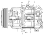
첨부된 도 1은 전술된 압축기 중 일반적인 가변용량형 사판식 압축기의 내부 구조를 나타내고 있다.BRIEF DESCRIPTION OF THE DRAWINGS Fig. 1 shows the internal structure of a general variable capacity swash plate type compressor among the above-mentioned compressors.
이를 토대로 알 수 있듯이, 일반적인 가변용량형 사판식 압축기는 구동축(40)에 경사각이 가변되도록 사판(30)을 장착함과 더불어 이 사판(30)의 둘레를 따라 복수의 피스톤(50)을 설치하여, 상기 구동축(40)의 회전 구동에 의해 상기 각 피스톤(50)이 실린더블록(10)의 실린더보어(12) 내부를 전후 왕복 운동하면서 냉매를 압축시키도록 구성된다.The
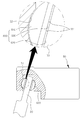
한편, 첨부된 도 2와 같이 상기 피스톤(50)에는 상기 사판(30)의 둘레측 끝단 부위가 수용되는 수용홈(51)이 형성됨과 더불어 상기 수용홈(51)의 내벽에는 반구형 슈(shoe)(60)의 개재를 위한 포켓부(52)가 구비된다.2, a
상기 슈(60)는 상기 사판(30)의 측벽에 접촉된 상태로 상기 사판(30)의 회전 동작에 따른 구동력을 상기 피스톤(50)으로 전달하는 역할을 수행하며, 이로 인해 상기 슈(60)와 상기 사판(30) 간의 접촉 부위에는 오일(윤활유)이 제공되어야 한다.The
즉, 상기 슈(60)와 사판(30) 간의 접촉 부위에 오일을 제공함으로써 서로 간의 마찰에 의한 마모의 발생이나 소음의 발생을 줄일 수 있도록 한 것이다.That is, oil is supplied to a contact portion between the
하지만, 상기한 슈(60)와 사판(30) 간의 사이로 오일이 제공되어 윤활이 이루어짐에도 불구하고 상기 슈(60)와 사판(30) 간의 접촉면적이 넓어서 서로 간의 면접촉에 의한 마찰력이 클 수밖에 없다는 문제점을 가지고 있다.However, even though oil is provided between the
특히, 상기 슈(60)와 상기 사판(30) 간의 넓은 접촉면적으로 인해 서로 간의 사이에 오일이 존재한다 하더라도 상기 오일에 의한 흡착력으로 순간적인 토크값 상승이 발생되었고, 이러한 토크값 상승에 의해 차량의 엔진에 부하가 제공됨으로써 연비의 저하가 야기될 수밖에 없다는 문제점 역시 가지고 있다.Particularly, due to the wide contact area between the
또한, 상기 사판(30)의 회전에 따라 마모가 발생되는 부위는 상기 슈(60)의 사판(30) 간이 접촉되는 면뿐만 아니라 상기 피스톤(50)의 포켓부(52) 내벽면과 접촉되는 슈(60)의 외면 역시 마모가 발생되었다.The portion of the
물론, 종래에는 국내공개특허공보 제10-2006-0119489호에 개시된 바와 같이 상기 슈(60)의 중심을 관통하는 오일유로를 형성함과 더불어 사판(30)의 표면 중 상기 슈(60)와의 접촉 부위를 따라서는 오일홈을 형성함으로써 상기 슈(60)와 상기 포켓부(52) 내벽면 간으로 오일이 제공될 수 있도록 하였지만, 전술된 종래 기술은 상기 오일유로를 통해 상기 포켓부(52) 내로 오일이 유동되는 양이 극히 미미하여 실질적인 효과를 기대할 수 없었으며, 사판(30)에 오일홈을 형성함에 따른 구조 변경에 의해 제품 신뢰성에 대한 고려가 추가로 수행되어야만 한다는 문제점을 가지고 있다.Of course, as described in Korean Patent Laid-Open Publication No. 10-2006-0119489, an oil passage passing through the center of the
본 발명은 전술된 종래 기술에 따른 각종 문제점을 해결하기 위해 안출된 것으로써, 본 발명의 목적은 슈와 사판 간의 접촉 면적을 줄여 서로 간의 접촉에 따라 발생되는 마찰력을 최소화할 수 있도록 하면서도 슈와 포켓부 간의 접촉 부위로도 오일의 원활한 제공이 가능하도록 한 새로운 형태에 따른 사판식 압축기용 슈를 제공하는데 있다.It is an object of the present invention to reduce the contact area between a shoe and a swash plate so as to minimize a frictional force generated by contact between the shoe and the swash plate, The present invention provides a swash plate type compressor shoe according to the present invention.
상기한 목적을 달성하기 위한 본 발명의 사판식 압축기용 슈에 따르면 엔진의 구동력을 전달받아 회전되는 구동축과, 상기 구동축에 경사지게 설치된 사판과, 상기 사판의 둘레를 따라 설치되면서 상기 사판의 회전에 의해 실린더보어 내부를 전후 왕복 운동하면서 냉매를 압축하는 복수의 피스톤과, 상기 사판과 상기 피스톤 간의 결합 부위에 제공되는 슈(shoe)를 포함하는 사판식 압축기에 있어서, 상기 슈는 곡면부와 평면부를 갖는 반구 형상으로 형성되면서 상기 곡면부는 상기 피스톤의 포켓부 내에 수용됨과 더불어 상기 평면부는 상기 사판과 접촉되도록 설치되고, 상기 슈의 평면부에는 그 중심으로부터 외곽측에 이르기까지 오일의 유동을 안내함과 더불어 상기 사판과의 접촉 면적을 줄이기 위한 오일홈이 요입 형성됨을 특징으로 한다.According to an aspect of the present invention, there is provided a shoe for a swash plate compressor, including: a drive shaft that is rotated by receiving a driving force of an engine; a swash plate that is inclined to the drive shaft; A swash plate compressor comprising: a plurality of pistons for compressing a refrigerant while reciprocating back and forth in a cylinder bore; and a shoe provided at a joint portion between the swash plate and the piston, wherein the shoe has a curved surface portion and a flat surface portion The curved surface portion is accommodated in the pocket portion of the piston while the flat surface portion is provided to be in contact with the swash plate. The flat surface portion of the shoe guides the flow of the oil from the center to the outer side, And an oil groove is formed to reduce the contact area with the swash plate.
여기서, 상기 오일홈은 복수로 형성되며, 상기 복수의 오일홈들은 상기 슈를 이루는 평면부의 중심으로부터 서로 다른 방사 방향을 향해 각각 형성됨을 특징으로 한다.Here, the plurality of oil grooves are formed in the radial direction from the center of the plane portion of the shoe, respectively.
이와 함께, 상기 각 오일홈은 서로 등 간격을 이루도록 형성됨을 특징으로 한다.In addition, each of the oil grooves is formed to be equally spaced from each other.
또한, 상기 오일홈의 양 측벽은 상기 오일홈 내의 바닥면으로부터 상기 슈를 이루는 평면부의 표면으로 갈수록 점차 외향 경사지게 형성됨을 특징으로 한다.Further, both side walls of the oil groove are gradually outwardly inclined from the bottom surface of the oil groove toward the surface of the flat surface forming the shoe.
이와 함께, 상기 오일홈의 양 측벽은 서로 다른 경사 각도를 갖도록 형성됨을 특징으로 한다.In addition, both side walls of the oil groove are formed to have different inclination angles.
이상에서와 같은 본 발명에 따른 사판식 압축기용 슈는 평면부에 복수의 오일홈을 추가로 형성함으로써 상기 슈와 사판 간의 접촉 면적을 줄여 토크값 감소를 이룰 수 있게 된 효과를 가진다.As described above, the swash plate type compressor shoe according to the present invention has the effect of reducing the torque value by reducing the contact area between the shoe and the swash plate by further forming a plurality of oil grooves in the flat surface portion.
특히, 상기한 오일홈은 평면부의 방사 방향을 따라 형성되도록 함으로써 슈의 회전에 따른 원심력에 의해 상기 오일홈 내의 오일이 상기 슈의 곡면부로 제공될 수 있도록 하여 상기 곡면부와 포켓부 간의 윤활이 원활히 이루어질 수 있게 된 효과를 가진다.Particularly, since the oil groove is formed along the radial direction of the flat surface portion, the oil in the oil groove can be provided to the curved surface portion of the shoe by the centrifugal force resulting from the rotation of the shoe, so that the lubricant between the curved surface portion and the pocket portion can be smoothly It is possible to achieve the effect.
또한, 본 발명에 따른 사판식 압축기용 슈는 오일홈의 양 측벽에 대한 경사 구조를 통해 사판의 회전에 의한 슈의 회전에 따라 오일을 펌핑하는 작용이 수행될 수 있음으로써, 오일이 상기 슈의 곡면부로 원활히 제공될 수 있게 된 효과를 가진다.The shoe for a swash plate compressor according to the present invention can perform an action of pumping oil according to the rotation of the shoe due to the rotation of the swash plate through the inclined structure with respect to both side walls of the oil groove, So that it can be smoothly provided to the curved surface portion.
도 1은 종래 일반적인 가변용량형 사판식 압축기의 내부 구조를 설명하기 위해 나타낸 단면도
도 2는 종래 일반적인 가변용량형 사판식 압축기의 피스톤과 슈 간의 결합 구조를 설명하기 위해 나타낸 분해 사시도
도 3은 본 발명의 바람직한 실시예에 따른 가변용량형 사판식 압축기의 내부 구조를 설명하기 위해 나타낸 단면도
도 4는 본 발명의 바람직한 실시예에 따른 가변용량형 사판식 압축기의 피스톤과 슈 간의 결합 구조를 설명하기 위해 나타낸 분해 사시도
도 5는 본 발명의 바람직한 실시예에 따른 가변용량형 사판식 압축기용 슈의 구조를 더욱 상세히 설명하기 위해 나타낸 확대 사시도
도 6은 도 5의 Ⅰ-Ⅰ선 단면도
도 7은 본 발명의 바람직한 실시예에 따른 가변용량형 사판식 압축기용 슈의 구조를 설명하기 위해 나타낸 평면도1 is a cross-sectional view illustrating an internal structure of a conventional variable capacity swash plate type compressor
2 is an exploded perspective view illustrating a coupling structure between a piston and a shoe of a conventional variable capacity swash plate type compressor.
3 is a cross-sectional view illustrating an internal structure of a variable capacity swash plate type compressor according to a preferred embodiment of the present invention.
FIG. 4 is an exploded perspective view illustrating a coupling structure between a piston and a shoe of a variable capacity swash plate type compressor according to a preferred embodiment of the present invention. FIG.
FIG. 5 is an enlarged perspective view illustrating a structure of a shoe for a variable capacity swash plate type compressor in accordance with a preferred embodiment of the present invention,
6 is a sectional view taken along the line I-I in Fig. 5
7 is a plan view illustrating a structure of a shoe for a variable capacity swash plate type compressor according to a preferred embodiment of the present invention.
이하, 본 발명의 사판식 압축기용 슈에 대한 바람직한 실시예를 첨부된 도 3 내지 도 7을 참조하여 설명하도록 한다.Hereinafter, a preferred embodiment of a shoe for a swash plate compressor of the present invention will be described with reference to FIGS. 3 to 7 attached hereto.
실시예의 설명에 앞서, 본 발명의 사판식 압축기용 슈는 가변용량형 사판식 압축기에 적용됨을 그 예로 한다.Prior to the description of the embodiments, the swash plate type compressor shoe of the present invention is applied to a variable displacement swash plate type compressor.
첨부된 도 3은 본 발명의 실시예에 따른 가변용량형 사판식 압축기의 내부 구조를 나타낸 상태도이다.FIG. 3 is a state diagram illustrating an internal structure of a variable capacity swash plate type compressor according to an embodiment of the present invention.
이를 토대로 알 수 있듯이, 본 발명의 실시예에 따른 가변용량형 사판식 압축기의 기본적인 구조는 종래의 일반적인 가변용량형 사판식 압축기와 동일하다.The basic structure of the variable displacement swash plate type compressor according to the embodiment of the present invention is the same as that of the conventional variable displacement swash plate type compressor.
즉, 압축기의 중심을 관통하면서 엔진의 구동력을 전달받아 회전되도록 설치되는 구동축(40)이 구비되고, 상기 구동축(40)의 어느 한 부위에는 경사각이 가변되도록 사판(30)이 설치되며, 상기 사판(30)의 둘레에는 상기 사판(30)의 회전에 의해 실린더보어(12) 내부를 전후 왕복 이동하면서 냉매를 압축하는 복수의 피스톤(50)이 설치되고, 상기 사판(30)과 상기 각 피스톤(50) 간의 결합 부위에는 한 쌍의 슈(600)(shoe)가 구비된다.A
한편, 첨부된 도 4는 본 발명의 실시예에 따른 가변용량형 사판식 압축기의 슈(600)와 피스톤(50) 간의 관계를 설명하기 위해 나타낸 분해 사시도이고, 첨부된 도 5는 본 발명의 실시예에 따른 가변용량형 사판식 압축기의 슈를 설명하기 위해 나타낸 사시도이며, 첨부된 도 6은 도 5의 Ⅰ-Ⅰ선 단면도이고, 첨부된 도 7은 슈의 오일홈이 형성된 부위를 설명하기 위해 나타낸 평면도이다.4 is an exploded perspective view illustrating a relationship between a
이를 토대로 알 수 있듯이, 본 발명의 실시예에 따른 가변용량형 사판식 압축기용 슈(600)는 곡면부(610)와 평면부(620)를 갖는 반구 형상으로 형성된다.As can be seen from this, the variable displacement swash
여기서, 상기 슈(600)의 곡면부(610)는 상기 피스톤(50)의 포켓부(52) 내에 수용됨과 더불어 상기 슈(600)의 평면부(620)는 상기 사판(30)의 측벽에 접촉되도록 설치되고, 상기 슈(600)의 평면부(620)에는 오일홈(630)이 요입 형성됨을 특징으로 제시하며, 이때 상기 오일홈(630)은 상기 평면부(620)의 중심으로부터 외곽측을 향하도록 형성된다.The
상기 오일홈(630)은 상기 슈(600)를 이루는 평면부(620)와 사판(30) 간의 접촉 면적을 최소화하기 위한 구조로써 상기한 오일홈(630)의 구성에 의해 상기 슈(600)의 평면부(620)와 사판(30) 간의 마찰력이 줄어들게 되고, 이로 인한 토크값의 감소에 의해 차량 엔진의 연비 감소를 이룰 수 있도록 한 것이다.The
물론, 상기 오일홈(630)은 전술된 마찰력의 감소를 위한 기능뿐만 아니라 사판(30)의 표면에 존재하면서 상기 슈(600)를 이루는 평면부(620)와의 윤활을 위한 오일을 상기 슈(600)의 곡면부(610)가 위치된 피스톤(50)의 포켓부(52) 내로도 제공될 수 있도록 하는 기능을 추가로 수행한다.Of course, the
즉, 상기 슈(600)의 평면부(620)가 상기 사판(30)의 표면에 접촉된 상태로 상기 피스톤(50)의 포켓부(52) 내에서 자전하는 동안 상기 평면부(620)에 형성된 오일홈(630) 내에 존재하는 오일이 상기 슈(600)의 원심력에 의해 슈(600)의 곡면부(610)로 제공될 수 있도록 하고, 이를 통해 상기 슈(600)의 곡면부(610)에 대한 윤활 역시 원활히 이루어질 수 있도록 함으로써 토크값의 추가적인 감소를 이룰 수 있도록 한 것이다.That is, the
특히, 상기 오일홈(630)은 복수로 형성되며, 상기 복수의 오일홈(630)들은 상기 슈(600)를 이루는 평면부(620)의 중심으로부터 서로 다른 방사 방향을 향해 각각 등간격을 이루면서 배치되도록 형성함으로써 상기 슈(600)를 이루는 곡면부(610)와 피스톤(50)의 포켓부(52) 간 접촉 부위로 상기 오일의 더욱 원활하면서도 균일한 공급이 가능하게 된다.Particularly, the
또한, 본 발명의 실시예에서는 상기 오일홈(630)의 양 측벽(631)이 첨부된 도 5 및 도 6과 같이 상기 오일홈(630) 내의 바닥면으로부터 상기 슈(600)의 평면부(620) 표면으로 갈수록 점차 외향 경사지게 형성됨을 추가적인 특징으로 제시한다.5 and 6, in which the both
상기와 같은 오일홈(630)의 측벽에(631) 대한 경사 구조는 사판(30)의 표면에 존재하는 오일이 상기 슈(600)의 평면부(620)에 형성된 오일홈(630) 내로 원활히 유입될 수 있도록 하기 위함이다. 즉, 수직한 구조에 비해 경사 구조가 평면부(620)와 사판(30) 간의 접촉면 사이에 존재하는 오일의 유입이 더욱 원활히 이루어질 수 있는 것이다.The inclined structure of the
특히, 본 발명의 실시예에서는 상기 오일홈(630)의 양 측벽(631)이 서로 다른 경사 각도를 갖도록 형성함을 추가로 제시하며, 이를 통해 어느 한 측벽(631)(경사각도가 상대적으로 큰 측벽)을 통해서는 오일이 원활히 유입될 수 있도록 함과 더불어 다른 한 측벽(631)(경사각도가 상대적으로 작은 측벽)에 의해 상기 오일홈(630) 내의 오일이 다시금 오일홈(630) 외부로 누출되지 않고, 해당 측벽(631)이 이루는 유로를 따라 안내되면서 곡면부(610)로의 오일 전달이 원활히 이루어질 수 있도록 한 것이다. 즉, 상기한 오일홈(630)의 양 측벽(631)에 대한 형상에 의해 곡면부(610)로의 오일 펌핑이 원활히 이루어질 수 있도록 한 것이다.Particularly, in the embodiment of the present invention, it is additionally proposed that both
하기에서는, 본 발명의 실시예에 따른 슈(600)의 작용에 대하여 더욱 구체적으로 설명하도록 한다.Hereinafter, the operation of the
먼저, 엔진의 구동에 따른 구동축(40)의 회전이 이루어질 경우 이 구동축(40)의 회전에 의해 사판(30) 역시 회전되며, 상기 사판(30)의 회전에 의해 상기 사판(30)의 둘레를 따라 설치된 복수의 피스톤(50)이 실린더보어(12) 내부를 전후 왕복 운동하면서 상기 실린더보어(12) 내로 제공된 냉매를 압축시키게 된다.When the
상기와 같은 압축기의 압축 운전이 진행되는 도중에는 상기 피스톤(50)과 상기 사판(30) 간의 결합 부위에 구비된 슈(600)가 상기 사판(30)의 회전 동작 및 상기 피스톤(50)의 전후 이동 동작에 연동하면서 회전 및 기울어짐 동작을 수행하게 된다.During the compression operation of the compressor as described above, the
즉, 상기 슈(600)를 이루는 평면부(620)는 상기 사판(30)의 측면에 접촉된 상태이기 때문에 상기 사판(30)의 회전에 의해 상기 슈(600) 역시 상기 피스톤(50)의 포켓부(52) 내에서 회전하게 되고, 이와 동시에 상기 사판(30)과의 접촉 위치가 변경됨에 따라 상기 슈(600)의 경사 각도가 지속적으로 변동되면서 상기 피스톤(50)의 포켓부(52) 내에서 기울어짐 동작을 반복하게 된다.That is, since the
또한, 상기 슈(600)의 회전 및 기울어짐 동작이 반복되는 도중에는 상기 슈(600)와 상기 사판(30) 간의 접촉면에 존재하는 오일이 상기 슈(600)의 평면부(620)에 형성된 오일홈(630) 내로 일부의 유입이 이루어지며, 이렇게 오일홈(630) 내로 유입된 오일은 상기 슈(600)의 회전에 의한 원심력 및 상기 오일홈(630) 내의 측벽(631)에 의한 안내를 받아 상기 슈(600)의 원주측으로 유동된 후 상기 슈(600)의 곡면부(610)를 타고 상기 곡면부(610)와 포켓부(52) 사이로 제공된다.The oil present on the contact surface between the
따라서, 상기 슈(600)는 상기 사판(30)과 접촉되는 평면부(620) 뿐만 아니라 상기 포켓부(52)에 접촉되는 곡면부(610) 모두가 상기 오일에 의해 원활히 윤활될 수 있게 되어 각 구성 간의 마찰에 따른 마모가 최소화될 수 있게 된다.Therefore, not only the
특히, 상기 평면부(620)에 형성된 오일홈(630)의 면적만큼 상기 사판(30)과의 접촉면적이 줄어듦에 따라 상기 사판(30)과 슈(600) 간의 마찰에 따른 토크값 상승은 최소화될 수 있으며, 이로 인한 엔진 부하의 감소가 가능하게 되어 연비 향상에 도움을 줄 수 있게 된다.Particularly, as the contact area with the
이렇듯, 본 발명에 따른 사판식 압축기용 슈(600)는 오일홈(630)의 구성과 이 오일홈(630)이 이루는 각 부위의 형상적 개선을 통해 접촉 부위의 원활한 윤활은 가능하면서도 마찰 면적의 최소화를 통한 토크값 감소를 이룰 수 있게 된 장점을 가진다.As described above, the swash
더욱이, 오일홈(630)의 양 측벽(631)에 대한 경사 구조를 통해 슈(600)가 진원을 이룰 수 있음으로써 제조 불량을 방지할 수 있게 된 장점을 가진다.Furthermore, the
한편, 본 발명에 따른 슈(600)는 가변용량형 사판식 압축기에 적용됨을 그 예로 하고 있지만, 이에 한정되지는 않는다. 즉, 본 발명에 따른 슈(600)는 사판(30)의 경사가 고정된 상태의 통상적인 사판식 압축기에도 적용할 수 있는 것이다.Meanwhile, although the
10. 실린더블록 12. 실린더보어
30. 사판 40. 구동축
50. 피스톤 51. 수용홈
52. 포켓부 60,600. 슈
610. 곡면부 620. 평면부
630. 오일홈 631. 측벽10.
30.
50.
52. Pocket part 60,600. Shoe
610.
630.
Claims (5)
상기 슈(600)는 곡면부(610)와 평면부(620)를 갖는 반구 형상으로 형성되면서 상기 곡면부(610)는 상기 피스톤(50)의 포켓부(52) 내에 수용됨과 더불어 상기 평면부(620)는 상기 사판(30)과 접촉되도록 설치되고,
상기 슈(600)의 평면부(600)에는 그 중심으로부터 외곽측에 이르기까지 오일의 유동을 안내함과 더불어 상기 사판(30)과의 접촉 면적을 줄이기 위한 오일홈(630)이 요입 형성됨을 특징으로 하는 사판식 압축기용 슈.A swash plate 30 mounted on the drive shaft 40 and slidably mounted on the drive shaft 40. The swash plate 30 is installed along the circumference of the swash plate 30, A plurality of pistons 50 for compressing the refrigerant while moving back and forth in the swash plate 12 and a shoe 600 provided at a coupling portion between the swash plate 30 and the piston 50, In the compressor,
The curved surface portion 610 is accommodated in the pocket portion 52 of the piston 50 and the flat surface portion 610 is formed in a shape of a hemispherical shape having a curved surface portion 610 and a flat surface portion 620, 620 are installed to be in contact with the swash plate 30,
An oil groove 630 is formed in the flat portion 600 of the shoe 600 to guide the flow of oil from the center to the outer side and to reduce the contact area with the swash plate 30 A shoe for a swash plate type compressor.
상기 오일홈(630)은 복수로 형성되며,
상기 복수의 오일홈(630)들은 상기 슈(600)를 이루는 평면부(620)의 중심으로부터 서로 다른 방사 방향을 향해 각각 형성됨을 특징으로 하는 사판식 압축기용 슈.The method according to claim 1,
The oil groove 630 is formed in plural,
Wherein the plurality of oil grooves (630) are formed respectively in the radial directions from the center of the plane portion (620) forming the shoe (600).
상기 각 오일홈(630)은 서로 등 간격을 이루도록 형성됨을 특징으로 하는 사판식 압축기용 슈.3. The method of claim 2,
Wherein each of the oil grooves (630) is formed to be equally spaced from each other.
상기 오일홈(630)의 양 측벽(631)은 상기 오일홈(630) 내의 바닥면으로부터 상기 슈(600)를 이루는 평면부(620)의 표면으로 갈수록 점차 외향 경사지게 형성됨을 특징으로 하는 사판식 압축기용 슈.The method according to claim 1,
Both side walls 631 of the oil groove 630 are gradually outwardly inclined toward the surface of the plane portion 620 forming the shoe 600 from the bottom surface of the oil groove 630. [ Shoe shoe.
상기 오일홈(630)의 양 측벽(631)은 서로 다른 경사 각도를 갖도록 형성됨을 특징으로 하는 사판식 압축기용 슈.
5. The method of claim 4,
Wherein both side walls (631) of the oil groove (630) are formed to have different inclination angles.
Priority Applications (1)
| Application Number | Priority Date | Filing Date | Title |
|---|---|---|---|
| KR1020130009373A KR20140096607A (en) | 2013-01-28 | 2013-01-28 | shoe for variable capacity swash plate type compressor |
Applications Claiming Priority (1)
| Application Number | Priority Date | Filing Date | Title |
|---|---|---|---|
| KR1020130009373A KR20140096607A (en) | 2013-01-28 | 2013-01-28 | shoe for variable capacity swash plate type compressor |
Publications (1)
| Publication Number | Publication Date |
|---|---|
| KR20140096607A true KR20140096607A (en) | 2014-08-06 |
Family
ID=51744424
Family Applications (1)
| Application Number | Title | Priority Date | Filing Date |
|---|---|---|---|
| KR1020130009373A KR20140096607A (en) | 2013-01-28 | 2013-01-28 | shoe for variable capacity swash plate type compressor |
Country Status (1)
| Country | Link |
|---|---|
| KR (1) | KR20140096607A (en) |
Cited By (2)
| Publication number | Priority date | Publication date | Assignee | Title |
|---|---|---|---|---|
| WO2019194497A1 (en) * | 2018-04-01 | 2019-10-10 | 엘지전자 주식회사 | Inter-prediction mode-based image processing method and apparatus therefor |
| KR20190127213A (en) | 2018-05-04 | 2019-11-13 | 한온시스템 주식회사 | Swash plate type compressor |
-
2013
- 2013-01-28 KR KR1020130009373A patent/KR20140096607A/en not_active Application Discontinuation
Cited By (2)
| Publication number | Priority date | Publication date | Assignee | Title |
|---|---|---|---|---|
| WO2019194497A1 (en) * | 2018-04-01 | 2019-10-10 | 엘지전자 주식회사 | Inter-prediction mode-based image processing method and apparatus therefor |
| KR20190127213A (en) | 2018-05-04 | 2019-11-13 | 한온시스템 주식회사 | Swash plate type compressor |
Similar Documents
| Publication | Publication Date | Title |
|---|---|---|
| US7186096B2 (en) | Swash plate type variable displacement compressor | |
| US4522112A (en) | Swash-plate type compressor having improved lubrication of swash plate and shoes | |
| KR20140096607A (en) | shoe for variable capacity swash plate type compressor | |
| US6393964B1 (en) | Compressor having piston rotation restricting structure with lubricating inclined guide surface | |
| KR20130033980A (en) | Compressor | |
| KR20060085002A (en) | The rotation-proof structure of piston, and variable displacement swash plate type compressor including the same | |
| JP2010180740A (en) | Hermetic compressor and refrigerating unit | |
| JPH10176656A (en) | Swash plate compressor | |
| US6523455B1 (en) | Compressor having an oil collection groove | |
| US8991300B2 (en) | Variable displacement swash plate type compressor | |
| JP3213891U (en) | Swash plate compressor | |
| KR101348854B1 (en) | Compressor | |
| KR100926405B1 (en) | Swash plate compressor | |
| US20060222513A1 (en) | Swash plate type variable displacement compressor | |
| KR20110035089A (en) | Swash plate type compressor | |
| JP3320587B2 (en) | Swash plate compressor | |
| US20140241925A1 (en) | Swash plate compressor | |
| JP2001165046A (en) | Compressor | |
| KR20110093200A (en) | Swash plate type compressor | |
| KR101142767B1 (en) | Piston for compressor | |
| KR20120027793A (en) | Compressor | |
| KR20130016437A (en) | Perforate hemispherical shoes for the swash plate compressor | |
| KR100682473B1 (en) | Piston for swash plate type compressor | |
| KR101721513B1 (en) | Swash plate type compressor | |
| KR20080099694A (en) | Swash plate type compressor |
Legal Events
| Date | Code | Title | Description |
|---|---|---|---|
| A201 | Request for examination | ||
| E902 | Notification of reason for refusal | ||
| E902 | Notification of reason for refusal | ||
| E601 | Decision to refuse application |