KR20140095554A - Novel solar module, supporting layer stacks and methods of fabricating thereof - Google Patents
Novel solar module, supporting layer stacks and methods of fabricating thereof Download PDFInfo
- Publication number
- KR20140095554A KR20140095554A KR1020147015862A KR20147015862A KR20140095554A KR 20140095554 A KR20140095554 A KR 20140095554A KR 1020147015862 A KR1020147015862 A KR 1020147015862A KR 20147015862 A KR20147015862 A KR 20147015862A KR 20140095554 A KR20140095554 A KR 20140095554A
- Authority
- KR
- South Korea
- Prior art keywords
- layer
- foam layer
- solar cell
- skin layers
- rigid foam
- Prior art date
Links
- 238000000034 method Methods 0.000 title claims description 69
- 239000006260 foam Substances 0.000 claims abstract description 121
- 239000010410 layer Substances 0.000 claims description 355
- -1 polyethylene terephthalate Polymers 0.000 claims description 41
- 239000012790 adhesive layer Substances 0.000 claims description 28
- 230000008569 process Effects 0.000 claims description 28
- 239000000463 material Substances 0.000 claims description 19
- 230000001070 adhesive effect Effects 0.000 claims description 15
- 229910052782 aluminium Inorganic materials 0.000 claims description 15
- XAGFODPZIPBFFR-UHFFFAOYSA-N aluminium Chemical compound [Al] XAGFODPZIPBFFR-UHFFFAOYSA-N 0.000 claims description 15
- 239000000853 adhesive Substances 0.000 claims description 14
- 238000004519 manufacturing process Methods 0.000 claims description 13
- 238000002844 melting Methods 0.000 claims description 10
- 230000008018 melting Effects 0.000 claims description 10
- 229920000139 polyethylene terephthalate Polymers 0.000 claims description 10
- 239000005020 polyethylene terephthalate Substances 0.000 claims description 10
- 239000004743 Polypropylene Substances 0.000 claims description 9
- 229920001155 polypropylene Polymers 0.000 claims description 9
- 239000002033 PVDF binder Substances 0.000 claims description 8
- 239000003365 glass fiber Substances 0.000 claims description 8
- 238000010438 heat treatment Methods 0.000 claims description 8
- 229920003207 poly(ethylene-2,6-naphthalate) Polymers 0.000 claims description 8
- 229920000515 polycarbonate Polymers 0.000 claims description 8
- 239000004417 polycarbonate Substances 0.000 claims description 8
- 239000011112 polyethylene naphthalate Substances 0.000 claims description 8
- 229920002981 polyvinylidene fluoride Polymers 0.000 claims description 8
- 229920000642 polymer Polymers 0.000 claims description 7
- 229920000098 polyolefin Polymers 0.000 claims description 7
- 229920002635 polyurethane Polymers 0.000 claims description 7
- 239000004814 polyurethane Substances 0.000 claims description 7
- DQXBYHZEEUGOBF-UHFFFAOYSA-N but-3-enoic acid;ethene Chemical compound C=C.OC(=O)CC=C DQXBYHZEEUGOBF-UHFFFAOYSA-N 0.000 claims description 6
- 239000005038 ethylene vinyl acetate Substances 0.000 claims description 6
- 229920001200 poly(ethylene-vinyl acetate) Polymers 0.000 claims description 6
- 229910052710 silicon Inorganic materials 0.000 claims description 6
- 239000010703 silicon Substances 0.000 claims description 6
- 239000010935 stainless steel Substances 0.000 claims description 6
- 229910001220 stainless steel Inorganic materials 0.000 claims description 6
- BFKJFAAPBSQJPD-UHFFFAOYSA-N tetrafluoroethene Chemical group FC(F)=C(F)F BFKJFAAPBSQJPD-UHFFFAOYSA-N 0.000 claims description 6
- RYGMFSIKBFXOCR-UHFFFAOYSA-N Copper Chemical compound [Cu] RYGMFSIKBFXOCR-UHFFFAOYSA-N 0.000 claims description 5
- 229910052802 copper Inorganic materials 0.000 claims description 5
- 239000010949 copper Substances 0.000 claims description 5
- 229910052751 metal Inorganic materials 0.000 claims description 5
- 239000002184 metal Substances 0.000 claims description 5
- 229920005989 resin Polymers 0.000 claims description 5
- 239000011347 resin Substances 0.000 claims description 5
- BQCIDUSAKPWEOX-UHFFFAOYSA-N 1,1-Difluoroethene Chemical compound FC(F)=C BQCIDUSAKPWEOX-UHFFFAOYSA-N 0.000 claims description 4
- OKTJSMMVPCPJKN-UHFFFAOYSA-N Carbon Chemical compound [C] OKTJSMMVPCPJKN-UHFFFAOYSA-N 0.000 claims description 4
- ZOKXTWBITQBERF-UHFFFAOYSA-N Molybdenum Chemical compound [Mo] ZOKXTWBITQBERF-UHFFFAOYSA-N 0.000 claims description 4
- 229920000571 Nylon 11 Polymers 0.000 claims description 4
- 229920000299 Nylon 12 Polymers 0.000 claims description 4
- 239000004697 Polyetherimide Substances 0.000 claims description 4
- 239000004698 Polyethylene Substances 0.000 claims description 4
- 239000004642 Polyimide Substances 0.000 claims description 4
- RTAQQCXQSZGOHL-UHFFFAOYSA-N Titanium Chemical compound [Ti] RTAQQCXQSZGOHL-UHFFFAOYSA-N 0.000 claims description 4
- 230000005540 biological transmission Effects 0.000 claims description 4
- 229910052799 carbon Inorganic materials 0.000 claims description 4
- 238000001816 cooling Methods 0.000 claims description 4
- 229910052750 molybdenum Inorganic materials 0.000 claims description 4
- 239000011733 molybdenum Substances 0.000 claims description 4
- 229910021421 monocrystalline silicon Inorganic materials 0.000 claims description 4
- QYSGYZVSCZSLHT-UHFFFAOYSA-N octafluoropropane Chemical compound FC(F)(F)C(F)(F)C(F)(F)F QYSGYZVSCZSLHT-UHFFFAOYSA-N 0.000 claims description 4
- 229920001707 polybutylene terephthalate Polymers 0.000 claims description 4
- 229910021420 polycrystalline silicon Inorganic materials 0.000 claims description 4
- 229920001601 polyetherimide Polymers 0.000 claims description 4
- 229920000573 polyethylene Polymers 0.000 claims description 4
- 229920013716 polyethylene resin Polymers 0.000 claims description 4
- 229920001721 polyimide Polymers 0.000 claims description 4
- 229920000582 polyisocyanurate Polymers 0.000 claims description 4
- 239000011495 polyisocyanurate Substances 0.000 claims description 4
- 239000004800 polyvinyl chloride Substances 0.000 claims description 4
- 229920000915 polyvinyl chloride Polymers 0.000 claims description 4
- 229920002620 polyvinyl fluoride Polymers 0.000 claims description 4
- 238000003825 pressing Methods 0.000 claims description 4
- SCUZVMOVTVSBLE-UHFFFAOYSA-N prop-2-enenitrile;styrene Chemical compound C=CC#N.C=CC1=CC=CC=C1 SCUZVMOVTVSBLE-UHFFFAOYSA-N 0.000 claims description 4
- 229920000638 styrene acrylonitrile Polymers 0.000 claims description 4
- 229910052719 titanium Inorganic materials 0.000 claims description 4
- 239000010936 titanium Substances 0.000 claims description 4
- MARUHZGHZWCEQU-UHFFFAOYSA-N 5-phenyl-2h-tetrazole Chemical compound C1=CC=CC=C1C1=NNN=N1 MARUHZGHZWCEQU-UHFFFAOYSA-N 0.000 claims description 3
- JBRZTFJDHDCESZ-UHFFFAOYSA-N AsGa Chemical compound [As]#[Ga] JBRZTFJDHDCESZ-UHFFFAOYSA-N 0.000 claims description 3
- 239000004593 Epoxy Substances 0.000 claims description 3
- 229910001218 Gallium arsenide Inorganic materials 0.000 claims description 3
- 229910001335 Galvanized steel Inorganic materials 0.000 claims description 3
- HVMJUDPAXRRVQO-UHFFFAOYSA-N copper indium Chemical compound [Cu].[In] HVMJUDPAXRRVQO-UHFFFAOYSA-N 0.000 claims description 3
- 229910021419 crystalline silicon Inorganic materials 0.000 claims description 3
- 239000008397 galvanized steel Substances 0.000 claims description 3
- 229920000554 ionomer Polymers 0.000 claims description 3
- 229920003229 poly(methyl methacrylate) Polymers 0.000 claims description 3
- 229920002037 poly(vinyl butyral) polymer Polymers 0.000 claims description 3
- 239000004926 polymethyl methacrylate Substances 0.000 claims description 3
- 229920001296 polysiloxane Polymers 0.000 claims description 3
- 238000011282 treatment Methods 0.000 claims description 3
- 229920001780 ECTFE Polymers 0.000 claims description 2
- 239000005977 Ethylene Substances 0.000 claims description 2
- 240000007182 Ochroma pyramidale Species 0.000 claims description 2
- 229920005549 butyl rubber Polymers 0.000 claims description 2
- 229920001577 copolymer Polymers 0.000 claims description 2
- 239000002023 wood Substances 0.000 claims description 2
- 229920002554 vinyl polymer Polymers 0.000 claims 2
- CHJAYYWUZLWNSQ-UHFFFAOYSA-N 1-chloro-1,2,2-trifluoroethene;ethene Chemical group C=C.FC(F)=C(F)Cl CHJAYYWUZLWNSQ-UHFFFAOYSA-N 0.000 claims 1
- QTBSBXVTEAMEQO-UHFFFAOYSA-M Acetate Chemical compound CC([O-])=O QTBSBXVTEAMEQO-UHFFFAOYSA-M 0.000 claims 1
- GYHNNYVSQQEPJS-UHFFFAOYSA-N Gallium Chemical compound [Ga] GYHNNYVSQQEPJS-UHFFFAOYSA-N 0.000 claims 1
- 229910052733 gallium Inorganic materials 0.000 claims 1
- 239000000758 substrate Substances 0.000 claims 1
- 238000007669 thermal treatment Methods 0.000 claims 1
- 210000004027 cell Anatomy 0.000 description 63
- 230000000750 progressive effect Effects 0.000 description 35
- 238000009434 installation Methods 0.000 description 14
- 239000011521 glass Substances 0.000 description 12
- 239000008393 encapsulating agent Substances 0.000 description 10
- 230000004224 protection Effects 0.000 description 6
- 230000005855 radiation Effects 0.000 description 6
- 239000013039 cover film Substances 0.000 description 5
- 238000004806 packaging method and process Methods 0.000 description 5
- 238000000429 assembly Methods 0.000 description 4
- 230000007613 environmental effect Effects 0.000 description 4
- 238000009413 insulation Methods 0.000 description 4
- 230000008901 benefit Effects 0.000 description 3
- 239000010408 film Substances 0.000 description 3
- XLYOFNOQVPJJNP-UHFFFAOYSA-N water Chemical compound O XLYOFNOQVPJJNP-UHFFFAOYSA-N 0.000 description 3
- VYPSYNLAJGMNEJ-UHFFFAOYSA-N Silicium dioxide Chemical compound O=[Si]=O VYPSYNLAJGMNEJ-UHFFFAOYSA-N 0.000 description 2
- 230000000712 assembly Effects 0.000 description 2
- WILFBXOGIULNAF-UHFFFAOYSA-N copper sulfanylidenetin zinc Chemical compound [Sn]=S.[Zn].[Cu] WILFBXOGIULNAF-UHFFFAOYSA-N 0.000 description 2
- 238000010586 diagram Methods 0.000 description 2
- ZZEMEJKDTZOXOI-UHFFFAOYSA-N digallium;selenium(2-) Chemical compound [Ga+3].[Ga+3].[Se-2].[Se-2].[Se-2] ZZEMEJKDTZOXOI-UHFFFAOYSA-N 0.000 description 2
- 230000005611 electricity Effects 0.000 description 2
- 239000000945 filler Substances 0.000 description 2
- 230000003287 optical effect Effects 0.000 description 2
- 238000012384 transportation and delivery Methods 0.000 description 2
- VGGSQFUCUMXWEO-UHFFFAOYSA-N Ethene Chemical compound C=C VGGSQFUCUMXWEO-UHFFFAOYSA-N 0.000 description 1
- 229920001046 Nanocellulose Polymers 0.000 description 1
- 230000006750 UV protection Effects 0.000 description 1
- QVGXLLKOCUKJST-UHFFFAOYSA-N atomic oxygen Chemical compound [O] QVGXLLKOCUKJST-UHFFFAOYSA-N 0.000 description 1
- 125000000484 butyl group Chemical group [H]C([*])([H])C([H])([H])C([H])([H])C([H])([H])[H] 0.000 description 1
- QXJJQWWVWRCVQT-UHFFFAOYSA-K calcium;sodium;phosphate Chemical compound [Na+].[Ca+2].[O-]P([O-])([O-])=O QXJJQWWVWRCVQT-UHFFFAOYSA-K 0.000 description 1
- 238000010276 construction Methods 0.000 description 1
- 230000008878 coupling Effects 0.000 description 1
- 238000010168 coupling process Methods 0.000 description 1
- 238000005859 coupling reaction Methods 0.000 description 1
- XUCNUKMRBVNAPB-UHFFFAOYSA-N fluoroethene Chemical group FC=C XUCNUKMRBVNAPB-UHFFFAOYSA-N 0.000 description 1
- 210000000497 foam cell Anatomy 0.000 description 1
- 229920001821 foam rubber Polymers 0.000 description 1
- 230000003301 hydrolyzing effect Effects 0.000 description 1
- 238000011900 installation process Methods 0.000 description 1
- 238000005304 joining Methods 0.000 description 1
- 239000012939 laminating adhesive Substances 0.000 description 1
- 239000003562 lightweight material Substances 0.000 description 1
- 230000007774 longterm Effects 0.000 description 1
- 238000012423 maintenance Methods 0.000 description 1
- 238000012986 modification Methods 0.000 description 1
- 230000004048 modification Effects 0.000 description 1
- 229910052760 oxygen Inorganic materials 0.000 description 1
- 239000001301 oxygen Substances 0.000 description 1
- 230000035515 penetration Effects 0.000 description 1
- 230000035699 permeability Effects 0.000 description 1
- 230000000704 physical effect Effects 0.000 description 1
- 229920000728 polyester Polymers 0.000 description 1
- 230000009467 reduction Effects 0.000 description 1
- 239000003566 sealing material Substances 0.000 description 1
- 239000000377 silicon dioxide Substances 0.000 description 1
- 239000002356 single layer Substances 0.000 description 1
- 239000007921 spray Substances 0.000 description 1
- 230000003068 static effect Effects 0.000 description 1
- 239000000126 substance Substances 0.000 description 1
- 230000003319 supportive effect Effects 0.000 description 1
Images


Classifications
-
- H—ELECTRICITY
- H01—ELECTRIC ELEMENTS
- H01L—SEMICONDUCTOR DEVICES NOT COVERED BY CLASS H10
- H01L31/00—Semiconductor devices sensitive to infrared radiation, light, electromagnetic radiation of shorter wavelength or corpuscular radiation and specially adapted either for the conversion of the energy of such radiation into electrical energy or for the control of electrical energy by such radiation; Processes or apparatus specially adapted for the manufacture or treatment thereof or of parts thereof; Details thereof
- H01L31/04—Semiconductor devices sensitive to infrared radiation, light, electromagnetic radiation of shorter wavelength or corpuscular radiation and specially adapted either for the conversion of the energy of such radiation into electrical energy or for the control of electrical energy by such radiation; Processes or apparatus specially adapted for the manufacture or treatment thereof or of parts thereof; Details thereof adapted as photovoltaic [PV] conversion devices
- H01L31/042—PV modules or arrays of single PV cells
- H01L31/048—Encapsulation of modules
- H01L31/0481—Encapsulation of modules characterised by the composition of the encapsulation material
-
- H—ELECTRICITY
- H01—ELECTRIC ELEMENTS
- H01L—SEMICONDUCTOR DEVICES NOT COVERED BY CLASS H10
- H01L31/00—Semiconductor devices sensitive to infrared radiation, light, electromagnetic radiation of shorter wavelength or corpuscular radiation and specially adapted either for the conversion of the energy of such radiation into electrical energy or for the control of electrical energy by such radiation; Processes or apparatus specially adapted for the manufacture or treatment thereof or of parts thereof; Details thereof
- H01L31/04—Semiconductor devices sensitive to infrared radiation, light, electromagnetic radiation of shorter wavelength or corpuscular radiation and specially adapted either for the conversion of the energy of such radiation into electrical energy or for the control of electrical energy by such radiation; Processes or apparatus specially adapted for the manufacture or treatment thereof or of parts thereof; Details thereof adapted as photovoltaic [PV] conversion devices
- H01L31/042—PV modules or arrays of single PV cells
-
- B—PERFORMING OPERATIONS; TRANSPORTING
- B32—LAYERED PRODUCTS
- B32B—LAYERED PRODUCTS, i.e. PRODUCTS BUILT-UP OF STRATA OF FLAT OR NON-FLAT, e.g. CELLULAR OR HONEYCOMB, FORM
- B32B15/00—Layered products comprising a layer of metal
- B32B15/04—Layered products comprising a layer of metal comprising metal as the main or only constituent of a layer, which is next to another layer of the same or of a different material
- B32B15/046—Layered products comprising a layer of metal comprising metal as the main or only constituent of a layer, which is next to another layer of the same or of a different material of foam
-
- B—PERFORMING OPERATIONS; TRANSPORTING
- B32—LAYERED PRODUCTS
- B32B—LAYERED PRODUCTS, i.e. PRODUCTS BUILT-UP OF STRATA OF FLAT OR NON-FLAT, e.g. CELLULAR OR HONEYCOMB, FORM
- B32B15/00—Layered products comprising a layer of metal
- B32B15/18—Layered products comprising a layer of metal comprising iron or steel
-
- B—PERFORMING OPERATIONS; TRANSPORTING
- B32—LAYERED PRODUCTS
- B32B—LAYERED PRODUCTS, i.e. PRODUCTS BUILT-UP OF STRATA OF FLAT OR NON-FLAT, e.g. CELLULAR OR HONEYCOMB, FORM
- B32B15/00—Layered products comprising a layer of metal
- B32B15/20—Layered products comprising a layer of metal comprising aluminium or copper
-
- B—PERFORMING OPERATIONS; TRANSPORTING
- B32—LAYERED PRODUCTS
- B32B—LAYERED PRODUCTS, i.e. PRODUCTS BUILT-UP OF STRATA OF FLAT OR NON-FLAT, e.g. CELLULAR OR HONEYCOMB, FORM
- B32B27/00—Layered products comprising a layer of synthetic resin
- B32B27/06—Layered products comprising a layer of synthetic resin as the main or only constituent of a layer, which is next to another layer of the same or of a different material
- B32B27/065—Layered products comprising a layer of synthetic resin as the main or only constituent of a layer, which is next to another layer of the same or of a different material of foam
-
- B—PERFORMING OPERATIONS; TRANSPORTING
- B32—LAYERED PRODUCTS
- B32B—LAYERED PRODUCTS, i.e. PRODUCTS BUILT-UP OF STRATA OF FLAT OR NON-FLAT, e.g. CELLULAR OR HONEYCOMB, FORM
- B32B7/00—Layered products characterised by the relation between layers; Layered products characterised by the relative orientation of features between layers, or by the relative values of a measurable parameter between layers, i.e. products comprising layers having different physical, chemical or physicochemical properties; Layered products characterised by the interconnection of layers
- B32B7/04—Interconnection of layers
- B32B7/12—Interconnection of layers using interposed adhesives or interposed materials with bonding properties
-
- H—ELECTRICITY
- H01—ELECTRIC ELEMENTS
- H01L—SEMICONDUCTOR DEVICES NOT COVERED BY CLASS H10
- H01L31/00—Semiconductor devices sensitive to infrared radiation, light, electromagnetic radiation of shorter wavelength or corpuscular radiation and specially adapted either for the conversion of the energy of such radiation into electrical energy or for the control of electrical energy by such radiation; Processes or apparatus specially adapted for the manufacture or treatment thereof or of parts thereof; Details thereof
- H01L31/04—Semiconductor devices sensitive to infrared radiation, light, electromagnetic radiation of shorter wavelength or corpuscular radiation and specially adapted either for the conversion of the energy of such radiation into electrical energy or for the control of electrical energy by such radiation; Processes or apparatus specially adapted for the manufacture or treatment thereof or of parts thereof; Details thereof adapted as photovoltaic [PV] conversion devices
- H01L31/042—PV modules or arrays of single PV cells
- H01L31/048—Encapsulation of modules
- H01L31/049—Protective back sheets
-
- H—ELECTRICITY
- H01—ELECTRIC ELEMENTS
- H01L—SEMICONDUCTOR DEVICES NOT COVERED BY CLASS H10
- H01L31/00—Semiconductor devices sensitive to infrared radiation, light, electromagnetic radiation of shorter wavelength or corpuscular radiation and specially adapted either for the conversion of the energy of such radiation into electrical energy or for the control of electrical energy by such radiation; Processes or apparatus specially adapted for the manufacture or treatment thereof or of parts thereof; Details thereof
- H01L31/18—Processes or apparatus specially adapted for the manufacture or treatment of these devices or of parts thereof
-
- H—ELECTRICITY
- H02—GENERATION; CONVERSION OR DISTRIBUTION OF ELECTRIC POWER
- H02S—GENERATION OF ELECTRIC POWER BY CONVERSION OF INFRARED RADIATION, VISIBLE LIGHT OR ULTRAVIOLET LIGHT, e.g. USING PHOTOVOLTAIC [PV] MODULES
- H02S20/00—Supporting structures for PV modules
-
- B—PERFORMING OPERATIONS; TRANSPORTING
- B32—LAYERED PRODUCTS
- B32B—LAYERED PRODUCTS, i.e. PRODUCTS BUILT-UP OF STRATA OF FLAT OR NON-FLAT, e.g. CELLULAR OR HONEYCOMB, FORM
- B32B2262/00—Composition or structural features of fibres which form a fibrous or filamentary layer or are present as additives
- B32B2262/10—Inorganic fibres
- B32B2262/101—Glass fibres
-
- B—PERFORMING OPERATIONS; TRANSPORTING
- B32—LAYERED PRODUCTS
- B32B—LAYERED PRODUCTS, i.e. PRODUCTS BUILT-UP OF STRATA OF FLAT OR NON-FLAT, e.g. CELLULAR OR HONEYCOMB, FORM
- B32B2266/00—Composition of foam
- B32B2266/02—Organic
- B32B2266/0214—Materials belonging to B32B27/00
- B32B2266/0264—Polyester
-
- B—PERFORMING OPERATIONS; TRANSPORTING
- B32—LAYERED PRODUCTS
- B32B—LAYERED PRODUCTS, i.e. PRODUCTS BUILT-UP OF STRATA OF FLAT OR NON-FLAT, e.g. CELLULAR OR HONEYCOMB, FORM
- B32B2266/00—Composition of foam
- B32B2266/08—Closed cell foam
-
- B—PERFORMING OPERATIONS; TRANSPORTING
- B32—LAYERED PRODUCTS
- B32B—LAYERED PRODUCTS, i.e. PRODUCTS BUILT-UP OF STRATA OF FLAT OR NON-FLAT, e.g. CELLULAR OR HONEYCOMB, FORM
- B32B2457/00—Electrical equipment
- B32B2457/12—Photovoltaic modules
-
- Y—GENERAL TAGGING OF NEW TECHNOLOGICAL DEVELOPMENTS; GENERAL TAGGING OF CROSS-SECTIONAL TECHNOLOGIES SPANNING OVER SEVERAL SECTIONS OF THE IPC; TECHNICAL SUBJECTS COVERED BY FORMER USPC CROSS-REFERENCE ART COLLECTIONS [XRACs] AND DIGESTS
- Y02—TECHNOLOGIES OR APPLICATIONS FOR MITIGATION OR ADAPTATION AGAINST CLIMATE CHANGE
- Y02E—REDUCTION OF GREENHOUSE GAS [GHG] EMISSIONS, RELATED TO ENERGY GENERATION, TRANSMISSION OR DISTRIBUTION
- Y02E10/00—Energy generation through renewable energy sources
- Y02E10/50—Photovoltaic [PV] energy
Landscapes
- Engineering & Computer Science (AREA)
- Physics & Mathematics (AREA)
- Condensed Matter Physics & Semiconductors (AREA)
- Electromagnetism (AREA)
- General Physics & Mathematics (AREA)
- Computer Hardware Design (AREA)
- Microelectronics & Electronic Packaging (AREA)
- Power Engineering (AREA)
- Manufacturing & Machinery (AREA)
- Photovoltaic Devices (AREA)
- Laminated Bodies (AREA)
Abstract
솔라셀을 기계적으로 지지하기 위한 솔라셀 지지층 스택이 개시된다. 솔라셀은: 경질 발포층(rigid foam layer); 경질 발포층에 인접하여 배치되는 하나 이상의 스킨층들을 포함하고, 경질 발포층 및 하나 이상의 스킨층들은 지지층 스택이 솔라셀에 인접하여 배치될 때 솔라셀을 지지하기 위한 기계적 지지를 제공한다.A cell-supported layer stack for mechanically supporting a solar cell is disclosed. The solar cell comprises: a rigid foam layer; Wherein the rigid foam layer and one or more skin layers provide mechanical support for supporting the solar cell when the support layer stack is disposed adjacent the solar cell.
Description
관련 출원Related application
본 출원은 모든 목적들을 위하여 본 명세서에 참조로써 통합된 2011.11.18에 출원된 미국 가특허출원 제61/561,337호에 대한 우선권을 주장한다.This application claims priority to U.S. Provisional Patent Application No. 61 / 561,337, filed on November 18, 2011, which is hereby incorporated by reference herein for all purposes.
기술분야Technical field
본 발명은 전반적으로 새로운 솔라 모듈, 지지층 스택들 및 그 제조방법들에 관한 것이다. 보다 구체적으로, 본 발명은 경질의, 기계적 지지성 발포층 및 적어도 하나의 스킨층을 이용하는, 새로운 솔라 모듈, 지지층 스택들 및 그 제조방법들에 관한 것이다.
The present invention generally relates to new solar module, support layer stacks and methods of making the same. More particularly, the present invention relates to new solar module, support layer stacks and methods of making thereof, which utilize a rigid, mechanically supportive foam layer and at least one skin layer.
종래의 솔라 모듈들은 전형적으로 지지 어셈블리를 형성하기 위하여 함께 적층되고 결합되는 재료들로 만들어진다. 지지 어셈블리는, 솔라 모듈 내에 배치되는 전기-생성 컴포넌트인 하나 이상의 솔라셀들을 봉입(enclose)한다. 이러한 구성에서, 지지 어셈블리는 유해한 환경적 요소들로부터 솔라셀들을 보호하고, 태양 에너지를 전기로 변환하는 프로세스를 용이하게 하는데 모두 기여한다.Conventional solar modules are typically made of materials that are laminated and bonded together to form a support assembly. The support assembly encloses one or more solar cells that are electro-generating components disposed within the solar module. In this configuration, the support assembly contributes both to protecting the solar cells from harmful environmental factors and facilitating the process of converting solar energy into electricity.
도 1은 유리로 만들어진 커버 시트(12)를 포함하는 종래의 솔라 모듈(10)의 분해 측면도를 도시한다. 유리 커버 시트(12) 다음에, "샌드위치-유사" 구조를 형성하기 위하여 봉지재들(encapsulants)(14 및 18)이 솔라셀(16)(예를 들어, 다결정 또는 단결정 실리콘 중 하나로 만들어진)의 양쪽 면들을 봉지하도록 제공된다. 봉지재(18)에 인접하여, 후방시트가 배치된다. 후방시트는 단일층 또는 복수의 층들로 구성되며, 솔라 모듈의 수명 및 안전을 보장하기 위한 복수의 기능들을 수행한다. 도 1은 적층 접착제(laminating adhesive)(22)에 의해 함께 결합되는 폴리머(polymeric) 절연층(dielectric layer)(20) 및 폴리머 후방 필름(24)을 포함하는 이러한 하나의 후방시트 설계를 도시한다. 폴리머 후방 필름(24)은 수분, UV, 및 기계적 손상에 대한 보호를 제공한다. 절연층(20)은, 솔라 모듈에 접근할 수 있는 설치자, 운송 요원, 정비 요원 및 소방관들이 전기 충격을 겪지 않도록 솔라 모듈(10)의 외부 부분을 솔라셀(16)로부터 전기적으로 격리한다. 이러한 안전 특징부는 고전압 시스템의 솔라 모듈들에 접촉하는 사람을 위해 특히 중요하다. 솔라 모듈(10)은 전형적으로 구조적 통합성을 제공하고, 유리 커버 시트(12)의 가장자리들을 보호하며, 모듈의 전기적 접지 및 설치를 위한 편리한 부착점을 제공하는, 알루미늄 프레임(예시를 단순화하기 위하여 도시되지 않음)에 의해 둘러싸인다. 솔라 모듈(10)에 있어, 솔라셀(16)과 알루미늄 프레임 사이에 배치되는 층들(12, 14, 18, 20, 22, 및 24)이 집합적으로 지지 어셈블리를 구성한다.Figure 1 shows an exploded side view of a conventional
종래의 모듈 어셈블리에 있어, 유리가 비용-효율적으로 솔라 모듈에 대한 구조적 지지부를 제공하고, 솔라셀들을 운송, 설치 및 사용 동안 손상으로부터 보호하며, 또한 솔라셀들을 수분, 눈, 우박, 및 바람으로 운반되는 잔해로부터 보호하기 때문에, 유리가 커버 시트(12)에 대한 바람직한 재료이다. 추가적으로, 유리의 높은 투명한 본질은 태양 에너지가 이를 통과하여 전기를 생성하는 솔라셀들 상에 충돌하게 한다. 태양 에너지를 최대화하고 효율적으로 활용하기 위하여, 봉지재들(14 및 18)이 태양 파장들에 대하여 실질적으로 투명하며, 이들은 전형적으로 모듈을 함께 결합하는 폴리머 접착제로 만들어진다. 도 1에 도시되고 이상에서 논의된 바와 같은 솔라 모듈(10)의 구성 및 다양한 컴포넌트들이 최초 솔라 모듈 설계로부터 변경되지 않아왔다In conventional module assemblies, glass provides a structural support for the solar module cost-effectively, protects the solar cells from damage during transportation, installation and use, and also protects the solar cells from moisture, snow, hail, Glass is the preferred material for the cover sheet 12 because it protects against debris being carried. In addition, the high transparent nature of the glass causes solar energy to pass through it and onto the solar cells producing electricity. To maximize and efficiently utilize solar energy, the
불행히도, 종래의 솔라 모듈들은 요구되고 전력이 획득되는 표면적에 대해 무거우며, 그에 따라 몇몇 단점들에 시달린다. 예로서, 종래 모듈의 중량 및 치수들은 모듈의 제조, 패키징, 운송, 설치 및 지지를 어렵고 비싸게 만든다. 종래의 솔라 모듈 및 그것의 알루미늄 프레임의 총 중량은 약 18 kg과 약 21 kg 사이이다. 그 크기 및 두께에 따라, 유리 커버 시트(전형적으로 모듈당 약 12 kg과 약 15 kg 사이의 무게인)가 모듈 중량의 대부분을 차지한다. 또한, 알루미늄 프레임을 갖는 솔라 모듈의 두께는 약 55 mm이다. 또한, 유리 커버 시트의 깨지기 쉬운 본질은 전체 솔라 모듈이 안전하게 패키징될 것을 요구하며, 이는 패키징 중량 및 비용을 증가시킨다.Unfortunately, conventional solar modules are heavy on the required surface area where power is obtained, and thus suffer from some disadvantages. By way of example, the weight and dimensions of conventional modules make manufacturing, packaging, transportation, installation and support of modules difficult and expensive. The total weight of a conventional solar module and its aluminum frame is between about 18 kg and about 21 kg. Depending on its size and thickness, a glass cover sheet (typically between about 12 kg and about 15 kg per module) accounts for the majority of the module weight. Further, the thickness of the solar module having the aluminum frame is about 55 mm. In addition, the fragile nature of the glass cover sheet requires that the entire solar module be safely packaged, which increases packaging weight and cost.
배송(shipping)과 관련하여, 종래의 솔라 모듈들의 중량 및 두께는 배송 컨테이너의 고정된 체적 내에 선적될 수 있는 모듈들의 양을 제한한다. 결과적으로, 많은 수의 모듈들이 요구되는 경우, 배송의 수가 증가하며, 이는 결국 배송 비용을 증가시킨다. 이러한 배송 비용은 설치가 지방 목적지들에서 수행될 때 또는 불충분한 운송 인프라가 존재하는 경우 더 악화된다.With regard to shipping, the weight and thickness of conventional solar modules limit the amount of modules that can be shipped within a fixed volume of the shipping container. As a result, if a large number of modules are required, the number of deliveries increases, which ultimately increases shipping costs. This delivery cost is exacerbated when the installation is performed at local destinations or when there is insufficient transport infrastructure.
설치와 관련하여, 종래 모듈의 중량 및 크기는 주거용, 상업용 및 유틸리티-규모의 애플리케이션들에 대한 설치 비용을 증가시킨다. 솔라 모듈은 전형적으로 빌딩의 옥상 또는 지반 구조물 상에 설치된다. 설치 전에, 각각의 모듈이 빌딩의 옥상으로 들어 올려지며, 그 뒤 희망되는 장소에 위치된다. 비교적 무겁고 큰 모듈들을 다루기 위하여, 이러한 설치-전 작업들은 리프팅, 조종 및 배치를 위하여 2명 이상의 설치자들을 요구한다. 일부 사례들에 있어, 너무 흔하게, 설치 비용을 증가시키는, 모듈들을 리프팅하기 위한 추가적인 수단(예를 들어, 크레인 또는 리프트)이 필요하다.With respect to installation, the weight and size of conventional modules increases installation costs for residential, commercial and utility-scale applications. Solar modules are typically installed on top of a building or on a geological structure. Prior to installation, each module is lifted to the roof of the building and then placed in the desired location. To handle relatively heavy and large modules, these pre-installation tasks require two or more installers for lifting, manipulating, and deploying. In some cases, too often, there is a need for additional means (e.g., a crane or lift) to lift the modules, which increases installation costs.
설치가 견고한 구조적 지지 시스템("지지 마운트(support mount)들"로서도 지칭되는)을 필요로 하기 때문에, 모듈의 중량이 또한 설치 비용을 증가시킨다. 설치 프로세스 동안, 지지 마운트들이 솔라 모듈을 빌딩 또는 독립형 시설에 견고하게 또는 확실하게 연결하는데 사용된다. 또한, 지지 마운트들은 솔라 모듈이 태양에 정렬되게 유지하고, 강풍 또는 폭설과 같은 악천후 동안 모듈이 손상되지 않게 한다. 가혹한 기상 요소가 없는 경우에도, 무거운 솔라 모듈들은 그 자체로 지붕 및 지지 마운트 상에 상당한 하중을 준다. 결과적으로, 지지 마운트들은 모듈들을 확실하게 고정하고, 강풍, 지진 및/또는 폭설로부터 실현되는 추가적인 하중에 견딜 수 있도록 설계된다. 이를 위하여, 지역, 주, 및 연방 건축 법규들 및 기술 표준들은 전형적으로 모듈들이 안전하고 의도된 대로 수행할 것을 보장하기 위해 이용되는 지지 마운트들을 규제한다. 더 무거운 솔라 모듈은 전형적으로 더 강한 지지 마운트들을 요구하며, 이는 설계, 구축 및 설치하는데 상대적으로 더 비싸다.Because the installation requires a robust structural support system (also referred to as "support mounts"), the weight of the module also increases installation costs. During the installation process, the support mounts are used to securely or reliably connect the solar module to a building or standalone facility. In addition, the support mounts keep the solar modules aligned with the sun and prevent damage to the module during bad weather such as strong winds or heavy snow. Even in the absence of harsh weather elements, heavy solar modules themselves give significant loads on the roof and support mounts. As a result, the support mounts are designed to securely secure the modules and withstand additional loads realized from strong winds, earthquakes and / or heavy snow. To this end, local, state, and federal building codes and technical standards typically regulate the support mounts used to ensure that modules perform safely and as intended. Heavier solar modules typically require stronger support mounts, which are relatively expensive to design, build and install.
따라서, 무거운 종래의 솔라 모듈 설계들에 의해 접하게 되는 단점들을 겪지 않는 솔라 모듈들의 새로운 설계들 및 이들을 제조하는 방법들에 대한 요구가 존재한다.
Thus, there is a need for new designs of solar modules that do not suffer from the disadvantages encountered by heavy conventional solar module designs and methods of manufacturing them.
이상을 고려하여, 본 발명은 새로운 솔라셀 지지층 스택 설계들, 솔라 모듈 설계들 및 이들을 만들기 위한 프로세스들을 제공한다. 일 측면에 있어, 본 발명은 솔라셀을 기계적으로 지지하기 위한 솔라셀 지지층 스택을 제공한다. 지지층 스택은: (i) 경질 발포층; 및 (ii) 경질 발포층에 인접하여 배치되는 하나 이상의 스킨층들;을 포함하고 및 (iii) 경질 발포층 및 하나 이상의 스킨층들은 지지층 스택이 솔라셀에 인접하여 배치될 때 솔라셀에 대한 기계적 지지를 제공할 수 있다.In light of the above, the present invention provides new solar cell support layer stack designs, solar module designs and processes for making them. In one aspect, the present invention provides a solar cell support layer stack for mechanically supporting a solar cell. The support layer stack comprises: (i) a rigid foam layer; And (ii) one or more skin layers disposed adjacent to the rigid foam layer, and (iii) the rigid foam layer and one or more skin layers are mechanically Support can be provided.
진보적인 지지층 스택들의 일 실시예에 있어, 경질 발포층이 하나 이상의 스킨층들 중 2개 사이에 샌드위치되며, 스킨층들 중 하나는 지지층 스택이 솔라셀에 인접하여 배치될 때 경질 발포층과 솔라셀 사이에 배치된다. 지지층 스택은 하나 이상의 스킨층들과 경질 발포층 사이에 배치된 접착층을 포함할 수 있다. 경질 발포층은 바람직하게, 폴리에틸렌 테레프탈레이트, 폴리우레탄, 폴리에테르이미드, 폴리메타크릴이마이드, 스티렌아크릴로니트릴, 폴리이미드, 폴리비닐클로라이드, 폴리비닐리덴 플루오라이드, 폴리카보네이트, 에틸렌 비닐 아세테이트, 발사 목재(balsa wood), 폴리이소시아누레이트, 폴리에틸렌, 탄소, 알루미늄, 폴리에틸렌 나프탈레이트, 폴리올레핀 및 폴리프로필렌으로 구성된 그룹으로부터 선택된 적어도 하나의 재료로 만들어진다. 본 발명의 보다 바람직한 실시예에 있어, 경질 발포 코어(core)는 폴리에틸렌 테레프탈레이트로 만들어질 수 있다. 발포층은 약 3 mm 내지 약 25 mm 사이의 두께를 가질 수 있다. 본 발명의 일 실시예에 따르면, 발포층은 약 25 kg/m3 내지 약 300 kg/m3 사이의 밀도를 갖는다.In one embodiment of the inventive support layer stacks, a rigid foam layer is sandwiched between two of the one or more skin layers, one of the skin layers having a rigid foam layer and a < RTI ID = Cells. The backing layer stack may include an adhesive layer disposed between the one or more skin layers and the rigid foam layer. The rigid foam layer is preferably made of a material selected from the group consisting of polyethylene terephthalate, polyurethane, polyetherimide, polymethacrylimide, styrene acrylonitrile, polyimide, polyvinyl chloride, polyvinylidene fluoride, polycarbonate, ethylene vinyl acetate, Is made of at least one material selected from the group consisting of balsa wood, polyisocyanurate, polyethylene, carbon, aluminum, polyethylene naphthalate, polyolefin and polypropylene. In a more preferred embodiment of the present invention, the rigid foam core may be made of polyethylene terephthalate. The foam layer may have a thickness between about 3 mm and about 25 mm. According to one embodiment of the present invention, the foam layer has a density between about 25 kg / m 3 and about 300 kg / m 3 .
본 발명의 특정 실시예들에 있어, 경질 발포층은 솔라셀들을 지지하기에 충분한 하중 지지 속성들을 가질 수 있다. 예로서, 발포층은 약 0.6 MPa 내지 약 7.5 MPa 사이의 압축 강도를 갖는다. 다른 예로서, 발포층은 약 40 MPa 내지 400 MPa 사이인 압축 모듈러스(modulus)를 갖는다. 또 다른 예로서, 발포층은 약 0.4 MPa 내지 4.5 MPa 사이의 전단 강도를 갖는다. 또 다른 예로서, 발포층은 약 10 MPa 내지 약 100 MPa 사이의 전단 모듈러스를 갖는다.In certain embodiments of the present invention, the rigid foam layer may have sufficient load bearing properties to support the solar cells. By way of example, the foam layer has a compressive strength between about 0.6 MPa and about 7.5 MPa. As another example, the foam layer has a compressive modulus between about 40 MPa and 400 MPa. As another example, the foam layer has a shear strength between about 0.4 MPa and 4.5 MPa. As another example, the foam layer has a shear modulus between about 10 MPa and about 100 MPa.
이상에서 언급된 하나 이상의 스킨층들은 바람직하게, 폴리비닐 플루오라이드, 테트라플루오로에틸렌의 폴리머, 헥사플루오로프로필렌 플루오라이드, 비닐리덴 플루오라이드, 폴리비닐리덴 플루오라이드, 테트라플루오로에틸렌 코-폴리머, 에틸렌 클로로트리플루오로에틸렌, 폴리에틸렌 테레프탈레이트, 폴리에틸렌 나프탈레이트, 폴리아미드-12; 폴리아미드-11, 폴리메틸 메타크랄레이트(methacralate), 폴리카보네이트, 폴리부틸렌 테레프탈레이트, 알루미늄, 스테인레스 강, 갈바니화된 강철, 티타늄, 구리, 몰리브데늄, 유리 섬유를 갖는 폴리에틸렌 수지 및 유리 섬유를 갖는 폴리프로필렌 수지로 구성된 그룹으로부터 선택된 적어도 하나의 재료로 만들어진다. 그러나, 본 발명의 보다 바람직한 일 실시예에 있어, 하나 이상의 스킨층들이 알루미늄으로 만들어진다. 본 발명의 보다 바람직한 대안적인 일 실시예에 있어, 하나 이상의 스킨층들이 스테인레스 강으로 만들어진다.The one or more skin layers mentioned above are preferably selected from the group consisting of polyvinyl fluoride, a polymer of tetrafluoroethylene, hexafluoropropylene fluoride, vinylidene fluoride, polyvinylidene fluoride, tetrafluoroethylene co- Ethylene chlorotrifluoroethylene, polyethylene terephthalate, polyethylene naphthalate, polyamide-12; Polyamide-11, polymethyl methacrylate, polycarbonate, polybutylene terephthalate, aluminum, stainless steel, galvanized steel, titanium, copper, molybdenum, polyethylene resin with glass fiber and glass fiber And at least one material selected from the group consisting of polypropylene resins having a polypropylene resin. However, in a more preferred embodiment of the present invention, one or more skin layers are made of aluminum. In one more preferred alternative embodiment of the present invention, one or more skin layers are made of stainless steel.
본 발명의 일 실시예에 있어, 하나 이상의 스킨층들은 약 0.025 mm 내지 약 3.0 mm 사이인 두께를 갖는다. 바람직하게 하나 이상의 스킨층들 중 적어도 하나는 지지층 스택이 솔라셀에 인접하여 배치될 때 지지층 스택을 솔라셀로부터 전기적으로 분리하는 절연층이다. 하나 이상의 스킨층들 중 적어도 하나가 태양 UV 에너지에 대하여 저항성일 수 있다. 또한, 하나 이상의 스킨층들 중 적어도 하나는 0.05 GM/m2/일(day) 미만의 증기 투과율(vapor transmission rate)을 가질 수 있다.In one embodiment of the present invention, the one or more skin layers have a thickness between about 0.025 mm and about 3.0 mm. Preferably at least one of the one or more skin layers is an insulating layer that electrically separates the support stack from the solar cell when the support stack is disposed adjacent the solar cell. At least one of the one or more skin layers may be resistant to solar UV energy. In addition, at least one of the one or more skin layers may have a vapor transmission rate of less than 0.05 GM / m 2 / day (days).
진보적인 지지층 스택은 하나 이상의 스킨층들과 경질 발포 코어 사이에 배치되는 접착층을 포함할 수 있다. 그러나, 본 발명의 대안적인 실시예에 있어, 접착제 없이 지지층 스택을 형성하기 위하여 발포층이 하나 이상의 스킨층들과 융합될 수 있다.The progressive backing layer stack may include an adhesive layer disposed between the one or more skin layers and the rigid foam core. However, in an alternative embodiment of the present invention, the foam layer can be fused with one or more skin layers to form a backing layer stack without adhesive.
다른 측면에 있어, 본 발명은 솔라 모듈을 제공한다. 솔라 모듈은: (i) 솔라셀; 및 (ii) 솔라셀에 인접하며, 솔라셀을 기계적으로 지지하는 솔라셀 지지층 스택을 포함한다. 이러한 측면에 있어, 솔라셀 지지층 스택은: (i) 경질 발포층; 및 (ii) 경질 발포층에 인접하여 배치되는 하나 이상의 스킨층들;을 포함하고 및 (iii) 경질 발포층 및 하나 이상의 스킨층들은 지지층 스택이 솔라셀에 인접하여 배치될 때 솔라셀에 대한 기계적 지지를 제공할 수 있다.In another aspect, the invention provides a solar module. Solar modules are: (i) solar cells; And (ii) a solar cell support layer stack adjacent to the solar cell and mechanically supporting the solar cell. In this aspect, the solar cell backing layer stack comprises: (i) a rigid foam layer; And (ii) one or more skin layers disposed adjacent to the rigid foam layer, and (iii) the rigid foam layer and one or more skin layers are mechanically Support can be provided.
진보적인 솔라 모듈들은 약 0.5 m 내지 약 3 m 사이의 폭을 가질 수 있고, 약 0.5 m 내지 약 3 m 사이의 길이를 가질 수 있으며, 약 4 mm 내지 약 25 mm 사이의 두께를 가질 수 있다. 본 발명의 솔라 모듈은 약 4 kg 내지 약 10 kg 사이의 중량일 수 있다.The progressive solar modules may have a width between about 0.5 m and about 3 m, a length between about 0.5 m and about 3 m, and a thickness between about 4 mm and about 25 mm. The solar modules of the present invention may be between about 4 kg and about 10 kg in weight.
솔라 모듈들 내부에 존재하는 솔라셀은 바람직하게, 다결정성 실리콘, 모노결정성 실리콘, 카드뮴 텔루라이드, 구리 인듐 갈륨 디셀레나이드(diselinide), 비결정성 단일 접합 실리콘, 비결정성 및 다결정성 이중 접합 실리콘, 결정성 실리콘, 갈륨 아르세나이드 및 구리 아연 틴 설파이드로 구성된 그룹으로부터 선택된 적어도 하나의 재료를 포함할 수 있다.The solar cells present inside the solar modules are preferably selected from the group consisting of polycrystalline silicon, monocrystalline silicon, cadmium telluride, copper indium gallium diselenide, amorphous uni-junction silicon, amorphous and polycrystalline double junction silicon , Crystalline silicon, gallium arsenide, and copper zinc tin sulfide.
또 다른 측면에 있어, 본 발명은 솔라셀 지지 스택을 제조하기 위한 프로세스를 제공한다. 프로세스는: (i) 경질 발포층을 획득하는 단계; (ii) 경질 발포층에 인접하여 배치될 하나 이상의 스킨층들을 획득하는 단계로서, 경질 발포층 및 하나 이상의 스킨층들은 지지층 스택이 솔라셀에 인접하여 배치될 때 솔라셀에 대한 기계적 지지를 제공할 수 있는, 단계; 및 (iii) 솔라셀 지지층 스택을 형성하기 위하여 경질 발포층과 하나 이상의 스킨층들 사이에 접착제를 도포하는 단계를 포함한다.In another aspect, the present invention provides a process for manufacturing a solar cell support stack. The process comprises the steps of: (i) obtaining a rigid foam layer; (ii) obtaining one or more skin layers to be disposed adjacent to the rigid foam layer, wherein the rigid foam layer and one or more skin layers provide mechanical support to the solar cell when the support layer stack is disposed adjacent the solar cell Can, step; And (iii) applying an adhesive between the rigid foam layer and the at least one skin layer to form a solar cell support layer stack.
경질 발포층과 하나 이상의 스킨층들 사이에 도포되는 접착제는 바람직하게, 에틸렌 비닐 아세테이트, 폴리우레탄, 실리콘, 폴리비닐 부티랄, 폴리올레핀, 이오노머, 에폭시, 부틸 고무-기반 접착제 및 페놀성-비닐(vinyl-phenolic)로 구성된 그룹으로부터 선택된 적어도 하나의 재료를 포함한다.The adhesive applied between the rigid foam layer and the one or more skin layers is preferably selected from the group consisting of ethylene vinyl acetate, polyurethane, silicone, polyvinyl butyral, polyolefin, ionomer, epoxy, butyl rubber- -phenolic). < / RTI >
또 다른 측면에 있어, 본 발명은 솔라셀 지지층 스택을 제조하는 다른 프로세스를 제공한다. 대안적인 지지층 스택을 제조하는 프로세스는: (i) 경질 발포층을 획득하는 단계; (ii) 경질 발포층에 인접하여 배치될 하나 이상의 스킨층들을 획득하는 단계로서, 경질 발포층 및 하나 이상의 스킨층들은 지지층 스택이 솔라셀에 인접하여 배치될 때 솔라셀에 대한 기계적 지지를 제공할 수 있는, 단계; 및 (iii) 가열된 경질 발포층 및 가열된 하나 이상의 스킨층들을 형성하기 위하여, 경질 발포층 및 하나 이상의 스킨층들을 경질 발포층의 용융점 또는 하나 이상의 스킨층들 중 임의의 스킨층의 용융점까지 또는 실질적으로 그 근처까지 가열하는 단계; 및 가열된 경질 발포층과 가열된 하나 이상의 스킨층들을 결합하고, 솔라셀 지지층 스택을 형성하기 위하여 압력을 가하는 단계를 포함한다.In yet another aspect, the present invention provides another process for fabricating a solar cell support layer stack. The process of making an alternative support layer stack comprises: (i) obtaining a rigid foam layer; (ii) obtaining one or more skin layers to be disposed adjacent to the rigid foam layer, wherein the rigid foam layer and one or more skin layers provide mechanical support to the solar cell when the support layer stack is disposed adjacent the solar cell Can, step; And (iii) heating the rigid foam layer and one or more skin layers to a melting point of the rigid foam layer or to the melting point of any of the one or more skin layers, or Heating substantially to near thereto; And combining the heated rigid foam layer with one or more heated skin layers and applying pressure to form a solar cell support layer stack.
본 발명의 일 실시예에 따르면, 발포층의 용융점은 약 160℃ 내지 약 275℃ 사이이다. 하나 이상의 스킨층들의 용융점은 약 200℃ 내지 약 240℃ 사이일 수 있다. 가열하는 단계는, 진공 백(vacuum bag)을 구비한 종래의 열 오븐, 핀치 롤러(pinch roller)들이 수반되는 적외선 오븐, 마이크로웨이브 오븐 프레스, 화염 처리(flame treatment), 가열형 핀치 롤러들, 유압 및 가열형 프레스, 오토클레이브(autoclave), 가열형 진공 백 및 연속적이고 가열된 금속 벨트들 모두를 갖는 플랫베드 라미네이터(flatbed laminator) 중 적어도 하나를 사용하는 열 처리를 제공하는 단계를 포함한다. 가열된 경질 발포층과 하나 이상의 가열된 스킨층들을 결합하기 위하여 가해지는 압력은 바람직하게 약 10 lbs/in2 내지 약 50 lbs/in2 사이이다. 일 실시예에 있어, 진보적인 프로세스들은 15분 미만의 지속기간 동안 압력을 가한다. 지지층 스택을 제조하는 진보적인 프로세스는 압력을 가하는 단계 이후 냉각된 솔라셀 지지층 스택을 형성하기 위하여 솔라셀 지지층 스택을 냉각하는 단계를 더 포함할 수 있다. 본 발명의 일 실시예에 의해 고려되는 바와 같은 냉각은 15분 미만의 지속기간을 가질 수 있다.According to one embodiment of the present invention, the melting point of the foam layer is between about 160 캜 and about 275 캜. The melting point of the one or more skin layers may be between about 200 < 0 > C and about 240 < 0 > C. The heating step may be performed using conventional heat ovens with vacuum bags, infrared ovens with pinch rollers, microwave oven presses, flame treatments, heated pinch rollers, hydraulic And a heat treatment using at least one of a heated press, an autoclave, a heated vacuum bag, and a flatbed laminator having both continuous and heated metal belts. The pressure applied to join the heated rigid foam layer and the one or more heated skin layers is preferably between about 10 lbs / in 2 and about 50 lbs / in 2 . In one embodiment, the progressive processes apply pressure for a duration of less than 15 minutes. The progressive process of fabricating the support layer stack may further include cooling the cell support layer stack to form a cooled cell support layer stack after the step of applying pressure. Cooling as contemplated by an embodiment of the present invention may have a duration of less than 15 minutes.
또 다른 측면에 있어, 본 발명은 솔라 모듈을 제조하는 프로세스를 제공한다. 솔라 모듈을 제조하는 프로세스는: (i) 솔라셀을 획득하는 단계; (ii) 솔라셀에 인접하여 배치될 솔라셀 지지층 스택을 획득하는 단계로서, 지지층 스택은: (a) 경질 발포층; 및 (b) 경질 발포층에 인접하여 배치되는 하나 이상의 스킨층들;을 포함하고 및 (c) 경질 발포층 및 하나 이상의 스킨층들은 지지층 스택이 솔라셀에 인접하여 배치될 때 솔라셀에 대한 기계적 지지를 제공할 수 있는, 단계; 및 (iii) 솔라 모듈을 형성하기 위하여 솔라셀과 솔라셀 지지층 스택 사이에 접착제를 도포하는 단계를 포함한다.In another aspect, the invention provides a process for manufacturing a solar module. A process for manufacturing a solar module includes: (i) obtaining a solar cell; (ii) obtaining a cell-cell support layer stack to be disposed adjacent to the solar cell, the support layer stack comprising: (a) a rigid foam layer; And (b) one or more skin layers disposed adjacent to the rigid foam layer, and (c) the rigid foam layer and one or more skin layers are mechanically Providing support; And (iii) applying an adhesive between the solar cell and the solar cell support layer stack to form a solar module.
그러나, 본 발명의 목적들 및 이점들과 함께, 본 발명의 동작의 구성 및 방법이 첨부된 도면들과 함께 읽을 때 특정 실시예들의 다음의 설명들로부터 더 양호하게 이해될 것이다.
However, together with objects and advantages of the present invention, the construction and method of operation of the present invention will be better understood from the following description of specific embodiments when read in conjunction with the accompanying drawings.
도 1은 종래의 솔라 모듈의 분해 측면도이다.
도 2는 본 발명의 일 실시예에 따른, 솔라셀 지지층 스택의 측면도를 도시한다.
도 3은 도 2에 도시된 예시적인 진보적 솔라셀 지지층 스택을 포함하는, 본 발명의 일 실시예에 따른 솔라 모듈의 분해 측면도를 도시한다.
도 4는 개재(interposed) 접착층을 사용하여 단일 스킨층에 부착된 경질 발포층을 갖는 다른 예시적인 진보적 지지층 스택을 포함하는, 본 발명의 다른 실시예에 따른, 솔라 모듈의 분해 측면도를 도시한다.
도 5는 개재 접착층 없이 2개의 스킨층들 사이에 샌드위치된 경질 발포층을 갖는 또 다른 예시적인 진보적 지지층 스택을 포함하는, 본 발명의 또 다른 실시예에 따른, 솔라 모듈의 분해 측면도를 도시한다.
도 6은 진보적인 솔라 모듈들(예를 들어, 도 3 및 도 4에 도시된 솔라 모듈들)을 제조하는, 본 발명의 일 실시예에 따른, 프로세스의 순서도이다.
도 7은 다른 진보적인 솔라 모듈(예를 들어, 도 5에 도시된 솔라 모듈)을 제조하는, 본 발명의 다른 실시예에 따른, 프로세스의 순서도이다.1 is an exploded side view of a conventional solar module.
Figure 2 shows a side view of a solar cell support layer stack, in accordance with an embodiment of the present invention.
3 illustrates an exploded side view of a solar module according to an embodiment of the present invention, including the exemplary progressive solar cell support layer stack shown in FIG.
Figure 4 shows an exploded side view of a solar module according to another embodiment of the present invention, including another exemplary advanced support layer stack having a rigid foam layer attached to a single skin layer using an interposed adhesive layer.
Figure 5 shows an exploded side view of a solar module according to another embodiment of the present invention, including another exemplary advanced support layer stack having a rigid foam layer sandwiched between two skin layers without an intervening adhesive layer.
FIG. 6 is a flow diagram of a process, according to one embodiment of the present invention, for producing progressive solar modules (e.g., the solar modules shown in FIGS. 3 and 4).
Figure 7 is a flow diagram of a process, according to another embodiment of the present invention, to produce another progressive solar module (e.g., the solar module shown in Figure 5).
다음의 설명에 있어, 본 발명의 완전한 이해를 제공하기 위하여 다수의 특정 상세들이 기술된다. 그러나, 본 발명이 이러한 특정 상세들의 일부 또는 전부에 한정되지 않고 구현될 수 있다는 것이 당업자에게 자명할 것이다. 다른 사례들에 있어, 잘 알려진 프로세스 단계들이 본 발명을 불필요하게 모호하게 하는 것을 회피하기 위하여 상세하게 설명되지 않는다.In the following description, numerous specific details are set forth in order to provide a thorough understanding of the present invention. However, it will be apparent to those skilled in the art that the present invention may be embodied without being limited to some or all of these specific details. In other instances, well-known process steps have not been described in detail in order to avoid unnecessarily obscuring the present invention.
본 발명은 유리 커버 시트를 포함하지 않는 솔라셀 지지층 스택이 종래의 솔라 모듈 설계가 마주하게 되는 단점들을 극복한다는 것을 인식한다. 본 발명의 일 실시예에 따르면, 지지층 스택은, 종래의 어셈블리들에 있어, UV 방사, 수분, 눈, 우박, 및 바람으로 운반되는 잔해들에 견디도록 설계된 유리로 만들어지지 않은, 커버 시트를 포함한다. 바람직한 실시예에 있어, 진보적인 지지층 스택은 적절한 스킨층에 인접한 또는 이에 가까운 임의의 경질층을 포함한다. 그러나, 보다 바람직한 실시예에 있어, 진보적인 경질층은 발포층으로 구성된다. The present invention recognizes that a solar cell support layer stack that does not include a glass cover sheet overcomes the disadvantages faced by conventional solar module designs. According to one embodiment of the present invention, the support layer stack includes a cover sheet that is not made of glass designed to withstand UV radiation, moisture, snow, hail, and windy debris in conventional assemblies do. In a preferred embodiment, the progressive support layer stack comprises any rigid layer adjacent or near the appropriate skin layer. However, in a more preferred embodiment, the progressive hard layer consists of a foam layer.
본 명세서에서 사용되는 바와 같은 용어 "인접한(adjacent)"은, 상이한 층들이 "인접합" 것으로 특징화되고, 솔라 모듈 내부에서 또는 솔라셀 지지층 스택 내부에서 서로 접촉하도록 배치된 실시예들에 한정되지 않는다는 것이 주목 할만 하다. 오히려, 용어 "인접한"은 하나 이상의 중간층들이 2개의 "인접한" 층들 사이에 개재되는 이러한 실시예들을 또한 커버한다.The term " adjacent " as used herein is not limited to those embodiments in which the different layers are characterized as being "adjacent" and arranged to contact one another within the solar module or within the solar cell support layer stack It is noteworthy that it does not. Rather, the term "adjacent" also covers those embodiments in which one or more intermediate layers are interposed between two "adjacent" layers.
도 2는 전형적으로 접착층에 의해 하나 이상의 솔라셀들에 부착되는 예시적인 진보적 지지층 스택(120)을 도시한다. 지지층 스택(120)은 개재 접착층들(112 및 116)을 사용하여 2개의 스킨층들(110 및 118) 사이에 샌드위치된 경질 발포층(114)을 포함한다. 발포층(114)은 지지층(120)이 솔라 모듈 내에서 솔라셀과 조립될 때 솔라셀들에 대한 기계적 지지를 제공한다. 발포층(114)의 기계적 속성들의 예들은 전단 강도, 전단 모듈러스, 전단 신장도(shear elongation), 압축 강도, 압축 모듈러스, 충격 인성(예를 들어, 탄성), 및 내피로성을 포함한다.FIG. 2 illustrates an exemplary advanced
스킨층들(110 및 118)은, 발포 컴포넌트 및 솔라 모듈 전체에 대한 다른 주요 환경적-보호 속성들과 함께, 인장 강도, 인장 모듈러스, 압축 강도, 압축 모듈러스를 제공할 수 있다. 스킨층(110)은, 솔라 모듈 내부에서 솔라셀들을 스킨층(110) 외부의 컴포넌트들로부터 전기적으로 분리하는 절연층으로서 역할할 수 있다. 스킨층(118)은 바람직하게, 수분, UV 방사, 눈, 우박, 바람에 날린 잔해들과 같은, 환경적 요소들로부터의 발포층(114) 및 솔라셀들에 대한 보호를 제공한다.The skin layers 110 and 118 may provide tensile strength, tensile modulus, compressive strength, and compressive modulus, along with other major environmental-protective properties for the foam component and the entire solar module. The
접착층들(112 및 116)은 바람직하게, 솔라 모듈의 수명 동안 이러한 요소들을 함께 결합하는 본질적인 역할을 수행할 뿐만 아니라, 스킨들과 코어 사이의 인장력 및 전단력에 견딜 수 있다.The
도 3은 본 발명의 일 실시예에 따른 솔라 모듈(200)을 도시한다. 솔라 모듈(200)은 도 2에 도시된 지지층 스택(120)과 실질적으로 유사한 지지층 스택(220)을 포함한다. 솔라 모듈(200)은, 개재 접착층(204)에 의해 서로 부착된 커버 필름(202) 및 솔라셀들(206)을 포함한다. 커버 필름(202), 접착층(204) 및 솔라셀들(206)의 부분-어셈블리는 다른 접착층(208)에 의해 지지층 스택(220)에 부착된다. 이러한 구성에 있어, 접착층들(204 및 208)이 솔라셀들(206)을 샌드위치한다는 것이 주목 할만 하다. 본 발명의 바람직한 실시예에 있어, 접착층들(204 및 208)이 솔라셀들(206)을 봉지(encapsulate)하며, 따라서 일반적으로 "봉지재(encapsulant)들"로서 지칭된다. 봉지재들(204 및 208)은, 그들이 일찍이 알려진 바와 같이, 솔라 모듈에 작용하는 외부 힘들로부터의 솔라셀에 대한 추가적인 보호를 제공한다. 봉지재(208)에 인접하여, 도 2에서 설명된 바와 같은 지지층 스택이 배치된다. 도 3에 도시된 실시예에 있어, 지지층 스택(220)은 발포층(214)을 샌드위치하는 2개의 스킨층들(210 및 218)을 포함한다. 스킨층(210)과 발포층(214) 사이에, 그리고 발포층(214)와 스킨층(218) 사이에 각기 개재된 접착제들(212 및 216)은 솔라 모듈(200)의 동작 및 수명 동안 지지층 스택 부분-어셈블리(220)를 함께 유지한다.FIG. 3 illustrates a
본 발명의 바람직한 특정 실시예들에 있어, 진보적인 지지층 스택 부분-어셈블리들 내에 2개 이상의 스킨층들을 가져야만 할 필요는 없다. 도 4는 단일 스킨층을 갖는 지지층 스택을 포함하는, 본 발명의 다른 실시예에 따른, 솔라 모듈(300)을 도시한다.In certain preferred embodiments of the present invention, it is not necessary to have more than one skin layer in the progressive support layer stack portion-assemblies. FIG. 4 illustrates a
솔라 모듈(300)은, 도 3에 도시된 그들의 대응부분들, 즉, 커버 필름(202), 봉지재들(204 및 208), 및 솔라셀들(206)과 동일하거나 또는 실질적으로 유사한, 커버 필름(302), 봉지재들(304 및 308) 및 솔라셀들(206)을 포함한다. 또한, 스킨층(318), 접착층(316) 및 발포층(314)이 또한 도 3에 도시된 그들의 대응부분들, 즉, 스킨층(218), 접착층(216) 및 발포층(214)과 동일하거나 또는 실질적으로 유사하다. 도 4에 도시된 실시예에 있어, 스킨층(210) 및 접착층(212)에 대응하는 층들이 없다는 것이 주목 할만 하다. 스킨층 및 연관된 접착층의 부재는 최종적으로 생산되는 솔라 모듈(300)의 감소된 중량 및 더 낮은 제조 비용의 이점을 누리는 진보적인 지지층 스택들을 제공한다.The
그러나, 본 발명의 바람직한 특정 실시예들에 있어, 접착층들(예를 들어, 도 3의 접착층들(212 및 216))의 존재가 진보적인 지지층 스택 부분-어셈블리들을 함께 유지하는데 필수적이지 않다는 것이 또한 주목되어야 한다. 이를 위하여, 도 5는, 임의의 접착층을 사용하지 않고, 스킨층들(410 및 418) 사이에서 직접적으로 샌드위치되는 발포층(414)을 포함하는, 본 발명의 대안적인 실시예에 따른, 솔라 모듈(400)을 도시한다. 모든 다른 측면들에 있어, 도 5의 솔라 모듈(400)은 도 3의 솔라 모듈(200)과 실질적으로 유사하다. 다시 말해서, 커버 필름(402), 봉지재들(404 및 408), 솔라셀들(406)은 도 3의 그들의 대응부분들인 커버 필름(202), 봉지재들(204 및 208), 솔라셀들(206)과 동일하거나 또는 실질적으로 유사하다.However, it will also be appreciated that, in certain preferred embodiments of the present invention, the presence of adhesive layers (e.g.,
접착층들의 부재시, 도 5의 결과적인 지지층 스택(420)이 상대적으로 가벼운 중량이며, 제조하기에 저렴하고, 지지층 스택 또는 솔라 모듈 제조 프로세스 동안 감소된 목록의 재료들을 요구한다. 지지층 스택들 내에서 상이한 층들 사이에 높은 강도의 결합이 요구되는 이러한 애플리케이션들에 있어, 지지층 스택(120)이 본 발명의 바람직한 실시예를 나타낼 수 있다. In the absence of adhesive layers, the resulting
본 발명에 의해 고려되는 바와 같은 발포층(예를 들어, 도 2의 114, 도 3의 214, 도 4의 314, 도 5의 414)은, 반드시 발포고무(foam)로 만들어질 필요는 없으며, 솔라 모듈 내에서 솔라셀들에 대한 기계적인 지지를 제공할 수 있는 임의의 적절한 경질의, 가벼운 중량의 재료로 잘 만들어질 수 있다. 그러나, 발포층은 바람직하게, 폴리에틸렌 테레프탈레이트, 폴리우레탄, 폴리에테르이미드, 폴리메타크릴이마이드, 스티렌아크릴로니트릴, 폴리이미드, 폴리비닐클로라이드, 폴리비닐리덴 플루오라이드, 폴리카보네이트, 에틸렌 비닐 아세테이트, 발사 목재, 폴리이소시아누레이트, 폴리에틸렌, 탄소, 알루미늄, 폴리에틸렌 나프탈레이트, 폴리올레핀 및 폴리프로필렌으로 구성된 그룹으로부터 선택된 적어도 하나의 재료로 만들어질 수 있다.The foam layer (e.g., 114 of FIG. 2, 214 of FIG. 3, 314 of FIG. 4, 414 of FIG. 5) as contemplated by the present invention need not necessarily be made of foam, Can be made of any suitable rigid, lightweight material that can provide mechanical support for solar cells within the solar module. However, the foam layer is preferably made of a material selected from the group consisting of polyethylene terephthalate, polyurethane, polyetherimide, polymethacrylimide, styrene acrylonitrile, polyimide, polyvinyl chloride, polyvinylidene fluoride, polycarbonate, ethylene vinyl acetate, Can be made of at least one material selected from the group consisting of fired wood, polyisocyanurate, polyethylene, carbon, aluminum, polyethylene naphthalate, polyolefin and polypropylene.
진보적인 지지층 스택들 내부의 발포층은 솔라 모듈 내에서 솔라셀들에 대한 필요한 기계적 지지를 제공하는 적절한 두께일 수 있다. 본 발명의 일 실시예에 따르면, 진보적인 지지층 스택들의 내부의 발포층의 두께는 약 3 mm 내지 약 25 mm 사이이다. 그러나, 본 발명의 바람직한 실시예들에 있어, 발포층의 두께는 약 4 mm 내지 약 12 mm 사이이다. 유사하게, 본 발명의 보다 더 바람직한 실시예에 있어, 발포층의 두께는 약 5 mm 내지 약 10 mm 사이이다.The foam layer within the progressive support layer stacks may be of a suitable thickness to provide the necessary mechanical support for the solar cells in the solar module. According to one embodiment of the present invention, the thickness of the foam layer inside the progressive support layer stacks is between about 3 mm and about 25 mm. However, in preferred embodiments of the present invention, the thickness of the foam layer is between about 4 mm and about 12 mm. Similarly, in a more preferred embodiment of the present invention, the thickness of the foam layer is between about 5 mm and about 10 mm.
진보적인 지지층 스택들 내의 발포층의 밀도는 임의의 과도한 외부 힘에 견질 수 있는 필요한 강도를 갖는 솔라 모듈을 제공하는 임의의 값일 수 있다. 발포층 밀도는 약 25 kg/m3 내지 약 300 kg/m3 사이의 값일 수 있으며, 보다 바람직하게는 약 75 kg/m3 내지 약 250 kg/m3 사이의 값일 수 있고, 가장 바람직하게는 약 100 kg/m3 내지 약 200 kg/m3 사이의 값일 수일 수 있다.The density of the foam layer within the progressive support layer stacks can be any value that provides a solar module with the required strength that can withstand any excessive external forces. The density of the foam layer may be a value between about 25 kg / m 3 and about 300 kg / m 3 , more preferably between about 75 kg / m 3 and about 250 kg / m 3 , And may be a value between about 100 kg / m 3 and about 200 kg / m 3 .
본 발명의 특정 실시예들에 있어, 솔라 모듈은 애플리케이션들에서 마주하게 될 정적 힘 및 동적 힘들을 다루는데 필요한 강성(rigidity) 및 전단 강도를 제공할 수 있는, 충분한 하중 지지 속성들을 갖는 발포층을 갖는 것이 바람직하다. 이를 위하여, 당업자들에 의해 진보적인 지지층 스택들 내의 발포층의 압축 강도 값의 크기가 관련 있는 것으로 여겨질 수 있다. 이러한 값이 많이 생각되는 이러한 사례들에 있어, 진보적인 발포층들의 압축 강도 값은 바람직하게 약 0.6 MPa 내지 약 7.5 MPa 사이이며, 보다 바람직하게는 약 1.0 MPa 내지 약 3.5 MPa 사이이고, 가장 바람직하게는 약 1.4 MPa 내지 약 2.5 MPa 사이이다. 다른 사례들에 있어, 당업자들이 압축 모듈러스를 발포층 강도의 중요한 척도로 여길 수 있다. 이러한 사례들에 있어, 진보적인 발포층의 압축 모듈러스 값은 약 40 MPa 내지 약 400 MPa 사이이며, 바람직하게는 약 75 MPa 내지 약 200 MPa 사이이고, 더 바람직하게는 약 100 MPa 내지 약 180 MPa 사이이다.In certain embodiments of the present invention, the solar module has a foam layer with sufficient load bearing properties that can provide the rigidity and shear strength needed to handle the static forces and dynamic forces encountered in applications . To this end, the magnitude of the compressive strength value of the foam layer within the advancing support layer stacks may be considered to be relevant by those skilled in the art. In these instances where these values are considered to be significant, the compressive strength values of the progressive foam layers are preferably between about 0.6 MPa and about 7.5 MPa, more preferably between about 1.0 MPa and about 3.5 MPa, Is between about 1.4 MPa and about 2.5 MPa. In other instances, one of ordinary skill in the art can view the compressive modulus as an important measure of the foam layer strength. In these instances, the compressive modulus value of the progressive foam layer is between about 40 MPa and about 400 MPa, preferably between about 75 MPa and about 200 MPa, and more preferably between about 100 MPa and about 180 MPa to be.
진보적인 발포층들의 전단 강도 값과 관련하여, 수용가능한 범위는 약 0.4 MPa 내지 약 4.5 MPa이다. 그러나, 바람직하게는, 전단 강도 값은 약 0.6 MPa 내지 약 3.0 MPa 사이이고, 보다 더 바람직하게는 약 0.8 MPa 내지 약 1.6 MPa 사이이다. 이러한 정도로 진보적인 발포층들과 연관된 전단 모듈러스 값 또는 전단 강도 값이 관련이 있는 것으로 여겨지며, 본 발명은 상대적으로 넓은 범위의 치수들을 고려한다. 예로서, 진보적인 발포층들에 대한 전단 모듈러스 값은 약 10 MPa 내지 약 100 MPa 사이이며, 바람직하게는 약 20 MPa 내지 약 75 MPa 사이이고, 더 바람직하게는 약 30 MPa 내지 약 60 MPa 사이이다.With respect to the shear strength values of the progressive foam layers, the acceptable range is from about 0.4 MPa to about 4.5 MPa. Preferably, however, the shear strength value is between about 0.6 MPa and about 3.0 MPa, and even more preferably between about 0.8 MPa and about 1.6 MPa. It is believed that shear modulus values or shear strength values associated with such progressive foam layers are relevant, and the present invention contemplates a relatively wide range of dimensions. By way of example, the shear modulus value for the progressive foam layers is between about 10 MPa and about 100 MPa, preferably between about 20 MPa and about 75 MPa, and more preferably between about 30 MPa and about 60 MPa .
지지층 스택에 대한 기계적 강도를 제공하는 것에 더하여 또는 이 대신에, 스킨층이 환경적 요소들로부터의 솔라셀 보호를 제공하는데 기여할 수 있다. 본 발명의 다른 특정 실시예들에 있어, 스킨층은 지지층 스택 부분-어셈블리에 절연 강도(dielectric strength)를 제공한다. 스킨층을 만드는데 사용되는 대표적인 재료들은 폴리비닐 플루오라이드, 테트라플루오로에틸렌의 폴리머, 헥사플루오로프로필렌 플루오라이드, 비닐리덴 플루오라이드, 폴리비닐리덴 플루오라이드, 테트라플루오로에틸렌 코-폴리머, 에틸렌 클로로트리플루오로에틸렌, 폴리에틸렌 테레프탈레이트, 폴리에틸렌 나프탈레이트, 폴리아미드-12, 폴리아미드-11, 폴리메틸 메타크랄레이트(methacralate), 폴리카보네이트, 폴리부틸렌 테레프탈레이트, 알루미늄, 스테인레스 강, 갈바니화된 강철, 티타늄, 구리, 몰리브데늄, 유리 섬유를 갖는 폴리에틸렌 수지 및 유리 섬유를 갖는 폴리프로필렌 수지로 구성된 그룹으로부터 선택된 적어도 하나의 재료를 포함한다.In addition to or instead of providing mechanical strength to the support layer stack, the skin layer can contribute to providing solar cell protection from environmental elements. In other specific embodiments of the present invention, the skin layer provides dielectric strength to the support layer stack portion-assembly. Representative materials used to make the skin layer include polyvinyl fluoride, polymers of tetrafluoroethylene, hexafluoropropylene fluoride, vinylidene fluoride, polyvinylidene fluoride, tetrafluoroethylene co-polymer, ethylene chlorotri But are not limited to, fluoroethylene, polyethylene terephthalate, polyethylene naphthalate, polyamide-12, polyamide-11, polymethyl methacrylate, polycarbonate, polybutylene terephthalate, aluminum, stainless steel, At least one material selected from the group consisting of titanium, copper, molybdenum, a polyethylene resin having glass fibers, and a polypropylene resin having glass fibers.
진보적인 지지층 스택들에 있어, 상이한 물리적 또는 화학적 속성들을 갖는 스킨층이 광범위한 환경적 요소들에 대한 보호를 제공한다. 중요한 속성들의 예들은: 기계적 강도, UV 저항성, 열 안정성, 가수분해 안정성(hydrolytic stability), 가연성, 산소 투과율 및 수증기 투과율을 포함한다. 적절한 두께의 발포층에 더하여, 적절한 두께의 스킨층이 또한 솔라 모듈 내에서 솔라셀들을 지지하는 진보적인 지지층 스택들의 기계적 강도에 기여한다. 본 발명의 일 실시예에 따르면, 하나 이상의 스킨층들의 두께는 약 0.025 mm 내지 3.0 mm 사이이며, 바람직하게는 약 0.100 mm 내지 약 1.0 mm 사이이고, 가장 바람직하게는 약 0.175 mm 내지 약 0.500 mm 사이이다.In progressive support layer stacks, a skin layer with different physical or chemical properties provides protection against a wide range of environmental factors. Examples of important properties include: mechanical strength, UV resistance, thermal stability, hydrolytic stability, flammability, oxygen permeability and water vapor transmission rate. In addition to the foam layer of appropriate thickness, a skin layer of appropriate thickness also contributes to the mechanical strength of the progressive support layer stacks supporting the solar cells in the solar module. According to one embodiment of the invention, the thickness of the one or more skin layers is between about 0.025 mm and 3.0 mm, preferably between about 0.100 mm and about 1.0 mm, and most preferably between about 0.175 mm and about 0.500 mm to be.
UV 방사에 대한 장기적인 노출은 폴리머 물리적 및 광학적 속성들의 품질을 떨어뜨린다. 따라서, 진보적인 지지층 스택들이 이러한 방사에 대한 저항성을 제공하고 유지하는 것이 바람직하다. 이를 위하여, 진보적인 지지층 스택들 내의 하나 이상의 스킨층들은 바람직하게 300 내지 400 nm 파장들 사이의 UV 방사에 대하여 100% 불투과성(opaque)이며, 간헐적인 수분 분무(water spray)를 갖는 42℃ 내지 63℃ 사이의 온도에서 0.35 Watt/m2의 UV 방사에 10,000 시간의 노출 후, 그들의 원래의 기계적 및 광학적 속성들의 80% 이상을 유지한다. 스킨층을 통한 수증기의 침투는 솔라셀, 발포고무, 및 봉지재의 수명 및 성능에 영향을 줄 수 있으며, 이는 솔라 모듈 도처에 사용되는 재료들의 긴 수명들 및 높은 성능들을 유지하게 하는 레벨로 감소되는 것이 바람직하다. 본 발명의 진보적인 지지층 스택들 내의 스킨층의 수증기 투과 저항(moisture vapor transmission resistance)에 대한 값은 약 0.05 gm/m2/일(day) 미만일 수 있으며, 보다 바람직하게는 0.005 gm/m2/일 미만의 값이며, 가장 바람직하게는 약 0.0005 gm/m2/일 미만의 값이다.Long term exposure to UV radiation degrades the quality of polymer physical and optical properties. Thus, it is desirable that progressive support layer stacks provide and maintain such a resistance to radiation. To this end, the one or more skin layers in the progressive support layer stacks are preferably 100% opaque to UV radiation between 300 and 400 nm wavelengths, and are characterized as having an intermittent water spray Maintain at least 80% of their original mechanical and optical properties after 10,000 hours exposure to 0.35 Watt / m < 2 > of UV radiation at a temperature of 63 [deg.] C. Penetration of water vapor through the skin layer can affect the life and performance of the solar cell, foam rubber, and encapsulant, which is reduced to a level that maintains long lifetimes and high performances of the materials used throughout the solar module . The value for the moisture vapor transmission resistance of the skin layer in the inventive support layer stacks may be less than about 0.05 gm / m 2 / day, more preferably less than about 0.005 gm / m 2 / Day, and most preferably less than about 0.0005 gm / m < 2 > / day.
하나 이상의 스킨층들이 지지층 스택 부분-어셈블리에 절연 강도를 제공하는 이러한 실시예들에 있어, 각각의 스킨층의 절연 강도는 약 750 볼트 내지 약 1,200 볼트 사이의 부분적 방전 전압 레벨을 초래할 정도로 충분히 높다. 본 발명의 바람직한 일 실시예에 있어, 알루미늄 또는 다른 전기 전도성 금속을 포함하는 하나의 스킨층이 솔라셀들로부터 가장 멀리에 배치되며(예를 들어, 도 2의 스킨층(118)), 환경적 요소들로부터의 보호를 제공하도록 설계된다. 이러한 실시예에 있어, 폴리에스테르 및 금속을 포함하는 다른 스킨층은 필요한 절연 강도를 제공하기 위하여 솔라셀들에 가까이 배치된다(예를 들어, 도 2의 스킨층(110)).In those embodiments in which one or more skin layers provide insulation strength to the support layer stack portion-assembly, the insulation strength of each skin layer is sufficiently high to result in a partial discharge voltage level between about 750 volts and about 1,200 volts. In one preferred embodiment of the present invention, one skin layer comprising aluminum or other electrically conductive metal is disposed furthest from the solar cells (e.g.,
접착층(예를 들어, 도 2의 접착층들(112 및 116))이 2개의 층들을 결합하기 위하여 발포층과 하나 이상의 스킨층들 사이에 배치되는 진보적인 지지층 스택들의 이러한 실시예들(예를 들어, 도 2, 도 3 및 도 4)에 있어, 접착층은 효율적으로 결합 기능을 수행하는 효율적인 접착제를 포함할 수 있다. 본 발명의 일 실시예에 있어, 접착층은, 에틸렌 비닐 아세테이트, 폴리우레탄, 실리콘, 폴리비닐 부티랄, 폴리올레핀, 이오노머, 에폭시, 부틸 고무-기반 접착제 및 페놀성-비닐로 구성된 그룹으로부터 선택된 재료를 포함한다. 이러한 접착층들은 일부 사례들에 있어 층에 강도를 제공하는 충전(filler) 재료들을 포함한다. 이러한 충전 재료들은, 예를 들어, 유리 구형체(glass sphere)들, 실리카 및 나노결정성 셀룰로오스를 포함한다.It is contemplated that the adhesive layer (e.g.,
진보적인 지지층 스택들은 임의의 특정 유형의 솔라셀과의 사용에 한정되지 않는다. 오히려, 진보적인 지지층 스택들은 솔라 모듈 내의 광범위한 솔라셀들과 함께 이용될 수 있다. 대표적인 솔라셀들은 다결정성 실리콘, 모노결정성 실리콘, 카드뮴 텔루라이드, 구리 인듐 갈륨 디셀레나이드, 비결정성 단일 접합 실리콘, 비결정성 및 다결정성 이중 접합 실리콘, 결정성 실리콘, 갈륨 아르세나이드 및 구리 아연 틴 설파이드를 포함한다.The progressive support layer stacks are not limited to use with any particular type of solar cell. Rather, progressive support stacks can be used with a wide range of solar cells in the solar module. Representative solar cells include polycrystalline silicon, monocrystalline silicon, cadmium telluride, copper indium gallium diselenide, amorphous single junction silicon, amorphous and polycrystalline double junction silicon, crystalline silicon, gallium arsenide and copper zinc Tin sulfide.
본 발명은 또한 진보적인 지지층 스택들 및 지지층 스택들(예를 들어, 지지층 스택들(도 2의 120, 도 3의 220, 도 4의 320) 중 하나)을 포함하는 진보적인 솔라 모듈들을 제조하기 위한 새로운 프로세스들을 제공한다. The present invention also relates to a method of fabricating advanced solar modules comprising advanced support layer stacks and support layer stacks (e.g., one of support layer stacks (120 of Figure 2, 220 of Figure 3, 320 of Figure 4) It provides new processes for
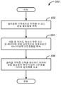
도 6은, 지지층 스택(예를 들어, 지지층 스택들(도 2의 120, 도 3의 220, 도 4의 320) 중 하나)을 제조하기 위한, 본 발명의 일 실시예에 따른, 프로세스(500)의 순서도를 도시한다. 프로세스(500)는 바람직하게, 경질 발포층(예를 들어, 발포층들(도 2의 114, 도 3의 214 및 도 4의 314) 중 하나)을 획득하는 단계를 포함하는 단계(502)에서 시작한다. 이상에서 언급된 바와 같이, 발포층은 하나 이상의 솔라셀들을 기계적으로 지지할 수 있다.Figure 6 illustrates a process 500 (according to one embodiment of the present invention) for fabricating a support layer stack (e.g., one of support layer stacks (120 of Figure 2, 220 of Figure 3, 320 of Figure 4) ). ≪ / RTI > The
다음으로, 단계(504)는 하나 이상의 스킨층들(예를 들어, 스킨층들(도 2의 110 및 118, 도 3의 210 및 218 및 도 4의 318) 중 하나)를 획득하는 단계를 포함한다. 도 6에서 이어서, 접착제(예를 들어, 개별적인 층의 형태일 수 있는, 접착층들(도 2의 112 및 116, 도 3의 212 및 216 및 도 4의 316) 중 적어도 하나)가 단계(506)에서 진보적인 층 스택을 형성하기 위하여 발포층과 하나 이상의 스킨층들 사이에 도포된다. 도 6의 단계(506)가 적어도 하나의 스킨층이 수분 또는 열 에너지에 대하여 실질적으로 불침투성일 것을 요구하지만, 본 발명이 이에 한정되는 것은 아니다. 본 발명의 스킨층은 임의의 특정 속성에 한정되지 않으며, 본 명세서에서 설명된 상이한 속성들 중 임의의 하나 또는 그 조합을 가질 수 있다.Next,
당업자들은 단계들(502, 504 및 506)이 임의의 특정 순서로 수행될 필요가 없으며, 도 5에 예시된 단계들의 시퀀스(sequence)가 진보적인 지지층 스택들을 결합하는 하나의 예시적 시퀀스라는 것을 인식할 것이다. 예로서, 단계(502) 후에, 단계(506)이 그 위에 접착제를 갖는 발포층을 생성하기 위하여 수행된다. 다음으로, 단계(504)가 스킨층을 발포층에 붙이고, 진보적인 지지층 스택을 형성하기 위하여 수행된다.Those skilled in the art will recognize that
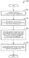
진보적인 프로세스들이 특정 시퀀스에 한정되지 않을 뿐만 아니라, 도 5의 진보적인 지지층 스택에 도시된 바와 같은 접착층을 사용함에 의한 접착 효과에 한정되지도 않는다. 이를 위하여, 본 발명은, 지지층 스택(예를 들어, 도 5의 지지층 스택(420))을 제조하기 위한, 본 발명의 다른 실시예에 따른, 프로세스(600)를 제공한다. 프로세스(600)는, 바람직하게, 경질 발포층을 획득하는 단계를 포함하는 단계(602)에서 시작한다. 단계(602)는 도 6의 단계(502)와 동일하거나 또는 실질적으로 유사하다. 다음으로, 프로세스(600)는 하나 이상의 스킨층들을 획득하는 단계를 포함하는 단계(604)로 진행하며, 이는 도 6의 단계(504)와 동일하거나 또는 실질적으로 유사하다.The progressive processes are not limited to a specific sequence, nor are they limited to the adhesive effect by using the adhesive layer as shown in the progressive support layer stack of FIG. To this end, the present invention provides a
그 뒤 단계(606)가 수행된다. 단계(606)는 가열된 발포층 및/또는 적어도 하나의 가열된 스킨층을 생성하기 위하여, 발포층 및/또는 하나 이상의 스킨층들을 발포층의 용융점 또는 스킨층들 중 임의의 하나의 용융점까지 또는 이에 가깝게 가열하는 단계를 포함한다.Step 606 is then performed. Step 606 may be repeated until the melting temperature of the foam layer and / or one or more skin layers has reached the melting point of any of the foam layers or the skin layers of any one of the skin layers to create a heated foam layer and / or at least one heated skin layer, And heating it closely.
단계(606)에서, 가열된 층들 중 임의의 하나가 발포층과 스킨층(들) 사이의 유효한 결합을 허용하는 정도로 용융되는 한, 가열된 층들 중 어떤 층이 용융되는지는 문제되지 않는다. 본 발명의 일 실시예에 있어, 발포 코어 및/또는 하나 이상의 스킨층들이 약 200℃의 온도까지 가열된다. 그러나, 발포층 및/또는 하나 이상의 스킨층들은 바람직하게 약 220℃까지 가열되며, 더 바람직하게는 약 230℃까지 가열된다.In
단계(606)는 특정 열처리 방법에 한정되지 않는다. 본 발명의 바람직한 특정 실시예들에 있어, 발포층 및/또는 하나 이상의 스킨층들이, 진공 백을 구비한 종래의 열 오븐, 핀치 롤러(pinch roller)들이 수반되는 적외선 오븐, 마이크로웨이브 오븐 프레스, 화염 처리(flame treatment), 가열형 핀치 롤러들, 유압 및 가열형 프레스, 오토클레이브(autoclave), 가열형 진공 백 및 연속적이고 가열된 금속 벨트들 모두를 갖는 플랫베드 라미네이터(flatbed laminator)로 구성된 그룹으로부터 선택된 하나의 방법에 의해 가열된다. 프로세스(600)는 진보적인 지지층 스택들을 형성하기 위하여 하나 이상의 가열된 스킨층들과 가열된 발포층을 결합하기 위하여 압력을 가하는 단계를 수반하는 단계(608)를 포함한다. 적절한 강도의 결합이 달성되는 한, 단계(608)에서 특정 압력 요건이 존재하지 않는다. 하나 이상의 가열된 스킨층들과 가열된 발포층에 가해지는 압력은 약 0 lbs/in2 내지 약 50 lbs/in2 사이이며, 더 바람직하게는 약 12 lbs/in2 내지 약 40 lbs/in2 사이이고, 가장 바람직하게는 약 15 lbs/in2 내지 약 30 lbs/in2 사이이다. 이러한 단계에서, 도 5에 도시된 것과 유사한 진보적인 지지층 스택이 형성된다. 그러나, 발포 코어와 하나 이상의 스킨들이 완전히 결합되는 것을 보장하기 위하여, 연속적인 압력이 바람직하게 약 10 분의 지속기간 동안 지지층 스택에 가해진다. 가해지는 압력의 더 짧은 지속기간이 또한 잘 동작할 수 있다. 예로서, 약 2 분 내지 약 5 분 사이의 범위의 지속기간들이 효율적으로 결합된 지지층 스택을 생성한다.Step 606 is not limited to a particular heat treatment method. In certain preferred embodiments of the present invention, the foam layer and / or one or more skin layers may be applied to a conventional heat oven with a vacuum bag, an infrared oven with pinch rollers, a microwave oven press, From a group consisting of flame treatment, heated pinch rollers, hydraulic and heated presses, autoclaves, heated vacuum bags and flatbed laminators with both continuous and heated metal belts And is heated by one selected method. The
진보적인 지지층 스택들을 제조하는데 어떠한 방법이 사용되었는지와 무관하게, 종래의 또는 비-종래의 커버 시트 및 솔라셀 층들이 잘 알려진 기술들에 따라 본 발명의 지지층 스택들에 부가될 수 있고, 진보적인 솔라 모듈들(예를 들어, 솔라 모듈들(도 2의 100, 도 3의 200, 도 4의 300 및 도 5의 400) 중 하나)을 형성한다. 결과적으로, 본 발명은 도 6의 프로세스(500) 또는 도 7의 프로세스(600)를 포함하는 진보적인 솔라 모듈 제조 프로세스들을 또한 제공한다.Regardless of which method is used to fabricate the progressive support layer stacks, conventional or non-conventional cover sheet and solar cell layers can be added to the support layer stacks of the present invention in accordance with well known techniques, (E.g., one of the solar modules (e.g., 100 of FIG. 2, 200 of FIG. 3, 300 of FIG. 4 and 400 of FIG. 5). As a result, the present invention also provides for advanced solar module manufacturing
진보적인 솔라 모듈들 및 지지층 스택들 그리고 이들을 제조하기 위한 새로운 프로세스들은 그들의 종래의 대응부분들을 뛰어 넘는 몇몇 이점들을 제공한다. 예로서, 유리 커버 시트를 사용하지 않음으로써, 그리고 솔라 모듈 또는 지지층 스택의 중량을 상당히 감소시킴으로써, 본 발명은 제조, 패키징, 운송 및 설치 비용의 절감을 실현한다. 진보적인 솔라 모듈의 총 중량은 약 4.0 kg 내지 약 10.0 kg 사이일 수 있으며, 바람직하게는 약 4.5 kg 내지 약 7.0 kg 사이이고, 더 바람직하게는 약 5.0 kg 내지 약 6.0 kg 사이이다. 가벼운 중량의 솔라 모듈들은 또한 그들 자신들을 운송하기 용이하게 한다. 결과적으로, 많은 양의 진보적인 솔라 모듈들이 배송 컨테이너의 고정된 체적 내에 선적될 수 있다. 또한, 가벼운 중량의 진보적인 솔라 모듈들은 지붕 및 지지 마운트들 상에 무거운 하중을 부과하지 않는다.Advanced solar modules and support layer stacks and new processes for fabricating them provide several advantages over their conventional counterparts. By way of example, by not using a glass cover sheet and by significantly reducing the weight of the solar module or support layer stack, the present invention realizes a reduction in manufacturing, packaging, transportation and installation costs. The total weight of the progressive solar module may be between about 4.0 kg and about 10.0 kg, preferably between about 4.5 kg and about 7.0 kg, and more preferably between about 5.0 kg and about 6.0 kg. Light weight solar modules also make transporting themselves easier. As a result, large quantities of advanced solar modules can be shipped within a fixed volume of the shipping container. In addition, light weight, advanced solar modules do not place heavy loads on the roof and support mounts.
제조, 패키징, 운송 및 설치와 연관된 상당한 비용 절감들이 또한 진보적인 지지층 스택들의 감소된 두께에 의해 실현된다. 예로서, 진보적인 솔라 모듈들의 두께는 약 4 mm 내지 약 25 mm 사이일 수 있으며, 더 바람직하게는 약 5.0 mm 내지 약 15 mm 사이이고, 가장 바람직하게는 약 6.0 mm 내지 약 10.0 mm 사이이다.Significant cost savings associated with manufacturing, packaging, shipping and installation are also realized by the reduced thickness of the advanced support layer stacks. By way of example, the thickness of the progressive solar modules may be between about 4 mm and about 25 mm, more preferably between about 5.0 mm and about 15 mm, and most preferably between about 6.0 mm and about 10.0 mm.
또한, 유리가 없는 경우, 솔라 모듈들 및 지지층 스택들에 대한 진보적인 설계들은, 운송 및 설치 동안의 안전 패키징을 포함하는 깨지기 쉬운 취급을 위해 고려되는 조치들에 대한 필요성을 제거한다. 진보적인 솔라 모듈들의 감소된 중량 및 두께 그리고 깨지기 쉬운 컴포넌트의 부재가 모두 다양한 비용 절감으로 변환되며, 이는 태양 에너지를 더 상업적으로 성공할 수 있는 대안적인 에너지 해법으로 만든다.Also, in the absence of glass, advanced designs for solar modules and support layer stacks eliminate the need for measures considered for fragile handling, including safe packaging during transportation and installation. The reduced weight and thickness of progressive solar modules and the absence of fragile components all translate into a variety of cost savings, making solar energy an alternative energy solution that can be more commercially successful.
본 발명의 예시적인 실시예들이 도시되고 설명되었지만, 다른 수정예들, 변경예들 및 대체물들이 의도된다. 예로서, 본 발명은 임의의 접착제를 사용하지 않는 발포층 및 적어도 하나의 스킨층의 가열 결합을 개시하며, 솔라 모듈 내의 다른 종래의 층들이 유사하게 결합될 수 있다. 따라서, 첨부된 청구항들은, 다음의 청구항들에 기술된 바와 같은, 본 발명의 범위에 부합하는 방식으로, 그리고 폭 넓게 해석되는 것이 적절하다.While illustrative embodiments of the present invention have been shown and described, other modifications, variations, and alternatives are contemplated. By way of example, the present invention discloses heat bonding of a foam layer and at least one skin layer without using any adhesive, and other conventional layers in the solar module can similarly be combined. Accordingly, it is appropriate that the appended claims be construed in a manner that is consistent with the scope of the invention, and as broadly interpreted, as set forth in the following claims.
Claims (36)
경질 발포층(rigid foam layer);
상기 경질 발포층에 인접하여 배치되는 하나 이상의 스킨층(skin layer)들;을 포함하며, 및
상기 경질 발포층 및 상기 하나 이상의 스킨층들은, 상기 지지층 스택이 상기 솔라셀에 인접하여 배치될 때, 상기 솔라셀에 대한 기계적 지지를 제공할 수 있는, 지지층 스택.
A solar cell support layer stack for mechanically supporting a solar cell,
A rigid foam layer;
And one or more skin layers disposed adjacent to the rigid foam layer,
Wherein the rigid foam layer and the one or more skin layers are capable of providing mechanical support to the solar cell when the support layer stack is disposed adjacent the solar cell.
상기 경질 발포층은 상기 스킨층들 중 2개에 의해 샌드위치되며,
상기 하나 이상의 스킨층들 중 하나는, 상기 지지층 스택이 상기 솔라셀에 인접하여 배치될 때, 상기 경질 발포층과 상기 솔라셀 사이에 배치되는, 지지층 스택.
The method according to claim 1,
The hard foam layer is sandwiched by two of the skin layers,
Wherein one of the one or more skin layers is disposed between the rigid foam layer and the solar cell when the supporting layer stack is disposed adjacent to the solar cell.
상기 하나 이상의 스킨층들과 상기 경질 발포층 사이에 배치되는 접착층을 더 포함하는, 지지층 스택.
The method according to claim 1,
Further comprising an adhesive layer disposed between the one or more skin layers and the rigid foam layer.
상기 경질 발포층은, 폴리에틸렌 테레프탈레이트, 폴리우레탄, 폴리에테르이미드, 폴리메타크릴이마이드, 스티렌아크릴로니트릴, 폴리이미드, 폴리비닐클로라이드, 폴리비닐리덴 플루오라이드, 폴리카보네이트, 에틸렌 비닐 아세테이트, 발사 목재(balsa wood), 폴리이소시아누레이트, 폴리에틸렌, 탄소, 알루미늄, 폴리에틸렌 나프탈레이트, 폴리올레핀 및 폴리프로필렌으로 구성된 그룹으로부터 선택된 적어도 하나의 재료로 만들어지는, 지지층 스택.
The method according to claim 1,
The hard foam layer may be formed of at least one selected from the group consisting of polyethylene terephthalate, polyurethane, polyetherimide, polymethacrylimide, styrene acrylonitrile, polyimide, polyvinyl chloride, polyvinylidene fluoride, polycarbonate, ethylene vinyl acetate, wherein the support layer stack is made of at least one material selected from the group consisting of balsa wood, polyisocyanurate, polyethylene, carbon, aluminum, polyethylene naphthalate, polyolefin and polypropylene.
상기 경질 발포층은 폴리에틸렌 테레프탈레이트로 만들어지는, 지지층 스택.
The method of claim 4,
Wherein the rigid foam layer is made of polyethylene terephthalate.
상기 경질 발포층은 약 3 mm와 약 25 mm 사이인 두께를 갖는, 지지층 스택.
The method according to claim 1,
Wherein the rigid foam layer has a thickness between about 3 mm and about 25 mm.
상기 경질 발포층은 약 25 kg/m3과 약 300 kg/m3 사이인 밀도를 갖는, 지지층 스택.
The method according to claim 1,
Wherein the rigid foam layer has a density between about 25 kg / m 3 and about 300 kg / m 3 .
상기 경질 발포층은 약 0.6 MPa과 약 7.5 MPa 사이인 압축 강도를 갖는, 지지층 스택.
The method according to claim 1,
Wherein the rigid foam layer has a compressive strength between about 0.6 MPa and about 7.5 MPa.
상기 경질 발포층은 약 40 MPa과 약 400 MPa 사이인 압축 모듈러스(modulus)를 갖는, 지지층 스택.
The method according to claim 1,
Wherein the rigid foam layer has a compressive modulus between about 40 MPa and about 400 MPa.
상기 경질 발포층은 약 0.4 MPa과 약 4.5 MPa 사이인 전단 강도를 갖는, 지지층 스택.
The method according to claim 1,
Wherein the rigid foam layer has a shear strength between about 0.4 MPa and about 4.5 MPa.
상기 경질 발포층은 약 10 MPa과 약 100 MPa 사이인 전단 모듈러스를 갖는, 지지층 스택.
The method according to claim 1,
Wherein the rigid foam layer has a shear modulus between about 10 MPa and about 100 MPa.
상기 하나 이상의 스킨층들은, 폴리비닐 플루오라이드; 테트라플루오로에틸렌의 폴리머, 헥사플루오로프로필렌 플루오라이드, 비닐리덴 플루오라이드; 폴리비닐리덴 플루오라이드; 테트라플루오로에틸렌 코-폴리머; 에틸렌 클로로트리플루오로에틸렌; 폴리에틸렌 테레프탈레이트; 폴리에틸렌 나프탈레이트, 폴리아미드-12; 폴리아미드-11 ; 폴리메틸 메타크랄레이트(methacralate); 폴리카보네이트; 폴리부틸렌 테레프탈레이트; 알루미늄, 스테인레스 강, 갈바니화된 강철, 티타늄, 구리, 몰리브데늄, 유리 섬유를 갖는 폴리에틸렌 수지 및 유리 섬유를 갖는 폴리프로필렌 수지로 구성된 그룹으로부터 선택된 적어도 하나의 재료로 만들어지는, 지지층 스택.
The method according to claim 1,
Wherein the one or more skin layers comprise polyvinyl fluoride; Polymers of tetrafluoroethylene, hexafluoropropylene fluoride, vinylidene fluoride; Polyvinylidene fluoride; Tetrafluoroethylene co-polymer; Ethylene chlorotrifluoroethylene; Polyethylene terephthalate; Polyethylene naphthalate, polyamide-12; Polyamide-11; Polymethyl methacralate; Polycarbonate; Polybutylene terephthalate; Wherein the support layer stack is made of at least one material selected from the group consisting of aluminum, stainless steel, galvanized steel, titanium, copper, molybdenum, polyethylene resins having glass fibers and polypropylene resins having glass fibers.
상기 하나 이상의 스킨층들은 알루미늄으로 만들어지는, 지지층 스택.
The method of claim 12,
Wherein the one or more skin layers are made of aluminum.
상기 하나 이상의 스킨층들은 스테인레스 강으로 만들어지는, 지지층 스택.
The method of claim 12,
Wherein the one or more skin layers are made of stainless steel.
상기 하나 이상의 스킨층들의 각각은 약 0.025 mm와 약 3.0 mm 사이인 두께를 갖는, 지지층 스택.
The method according to claim 1,
Wherein each of the one or more skin layers has a thickness between about 0.025 mm and about 3.0 mm.
상기 하나 이상의 스킨층들 중 적어도 하나는 절연층이며, 상기 절연층은 상기 지지층 스택이 상기 솔라셀에 인접하여 배치될 때 상기 지지층 스택을 상기 솔라셀로부터 전기적으로 분리하는, 지지층 스택.
The method according to claim 1,
Wherein at least one of the one or more skin layers is an insulating layer and the insulating layer electrically isolates the supporting layer stack from the solar cell when the supporting layer stack is disposed adjacent to the solar cell.
상기 하나 이상의 스킨층들 중 적어도 하나는 태양 UV 에너지에 대하여 저항성인, 지지층 스택.
The method according to claim 1,
Wherein at least one of the one or more skin layers is resistant to solar UV energy.
상기 하나 이상의 스킨층들 중 적어도 하나는 0.05 GM/m2/일(day) 미만의 증기 투과(vapor transmission)를 갖는, 지지층 스택.
The method according to claim 1,
Wherein at least one of the one or more skin layers has a vapor transmission of less than 0.05 GM / m 2 / day.
상기 경질 발포층은 상기 지지층 스택을 형성하기 위하여 상기 하나 이상의 스킨층들과 융합(fuse)되는, 지지층 스택.
The method according to claim 1,
Wherein the rigid foam layer is fused with the one or more skin layers to form the support layer stack.
솔라셀; 및
상기 솔라셀에 인접하며, 상기 솔라셀을 기계적으로 지지하는 솔라셀 지지층 스택으로서, 상기 솔라셀 지지층 스택은:
경질 발포층;
상기 경질 발포층에 인접하여 배치되는 하나 이상의 스킨층들;을 포함하며, 및
상기 경질 발포층 및 상기 하나 이상의 스킨층들은, 상기 지지층 스택이 상기 솔라셀에 인접하여 배치될 때, 상기 솔라셀에 대한 기계적인 지지를 제공할 수 있는, 상기 솔라셀 지지층 스택을 포함하는, 솔라 모듈.
As a solar module,
Solar cell; And
A solar cell support layer stack adjacent to the solar cell and mechanically supporting the solar cell, the solar cell support layer stack comprising:
Hard foam layer;
At least one skin layer disposed adjacent to the rigid foam layer, and
Wherein the rigid foam layer and the one or more skin layers are capable of providing mechanical support to the solar cell when the support layer stack is disposed adjacent the solar cell, module.
상기 솔라 모듈은, 약 0.5 m와 약 3.0 m 사이인 폭을 가지고, 약 0.5 m와 약 3.0 m 사이인 길이를 가지며, 약 4.0 mm와 약 25 mm 사이인 두께를 갖는, 솔라 모듈.
The method of claim 20,
The solar module having a width between about 0.5 m and about 3.0 m, a length between about 0.5 m and about 3.0 m, and a thickness between about 4.0 mm and about 25 mm.
상기 솔라 모듈은 약 4.0 kg과 약 10.0 kg 사이의 중량인, 솔라 모듈.
The method of claim 20,
Wherein the solar module is a weight between about 4.0 kg and about 10.0 kg.
상기 솔라셀은, 다결정성 실리콘, 모노결정성 실리콘, 카드뮴 텔루라이드, 구리 인듐 갈륨 디셀레나이드(diselinide), 비결정성 단일 접합 실리콘, 비결정성 및 다결정성 이중 접합 실리콘, 결정성 실리콘, 갈륨 아르세나이드 및 구리 아연 틴 설파이드로 구성된 그룹으로부터 선택된 적어도 하나의 재료를 포함하는, 솔라 모듈.
The method of claim 20,
Wherein the solar cell is selected from the group consisting of polycrystalline silicon, monocrystalline silicon, cadmium telluride, copper indium gallium diselinide, amorphous single junction silicon, amorphous and polycrystalline double junction silicon, crystalline silicon, gallium arsenide And at least one material selected from the group consisting of copper and zinc zinc tin sulfide.
경질 발포층을 획득하는 단계;
상기 경질 발포층에 인접하여 배치되는 하나 이상의 스킨층들을 획득하는 단계로서, 상기 경질 발포층 및 상기 하나 이상의 스킨층들은, 상기 지지층 스택이 상기 솔라셀에 인접하여 배치될 때, 상기 솔라셀에 대한 기계적인 지지를 제공할 수 있는, 단계;
상시 솔라셀 지지층 스택을 형성하기 위하여 상기 하나 이상의 스킨층들과 상기 경질 발포층 사이에 접착제를 도포하는 단계를 포함하는, 프로세스.
A process for fabricating a solar cell support layer stack,
Obtaining a hard foam layer;
Wherein the rigid foam layer and the one or more skin layers are arranged such that when the support layer stack is disposed adjacent to the solar cell, Which can provide mechanical support;
Applying an adhesive between said one or more skin layers and said rigid foam layer to form an always-on-cell support layer stack.
상기 경질 발포층을 획득하는 단계는, 폴리에틸렌 테레프탈레이트, 폴리우레탄, 폴리에테르이미드, 폴리메타크릴이마이드, 스티렌아크릴로니트릴, 폴리이미드, 폴리비닐클로라이드, 폴리비닐리덴 플루오라이드, 폴리카보네이트, 에틸렌 비닐 아세테이트, 발사 목재, 폴리이소시아누레이트, 폴리에틸렌, 탄소, 알루미늄, 폴리에틸렌 나프탈레이트, 폴리올레핀 및 폴리프로필렌으로 구성된 그룹으로부터 선택된 적어도 하나의 재료로 만들어진 층을 획득하는 단계를 포함하는, 프로세스.
27. The method of claim 24,
Wherein the step of obtaining the rigid foamed layer comprises the steps of: preparing a rigid foamed layer comprising at least one of polyethylene terephthalate, polyurethane, polyetherimide, polymethacrylimide, styrene acrylonitrile, polyimide, polyvinyl chloride, polyvinylidene fluoride, polycarbonate, ethylene vinyl Comprising the step of obtaining a layer made of at least one material selected from the group consisting of acetate, fired wood, polyisocyanurate, polyethylene, carbon, aluminum, polyethylene naphthalate, polyolefin and polypropylene.
상기 하나 이상의 스킨층들을 획득하는 단계는, 폴리비닐 플루오라이드, 테트라플루오로에틸렌의 폴리머, 헥사플루오로프로필렌 플루오라이드, 비닐리덴 플루오라이드, 폴리비닐리덴 플루오라이드, 테트라플루오로에틸렌 코-폴리머, 에틸렌 클로로트리플루오로에틸렌, 폴리에틸렌 테레프탈레이트, 폴리에틸렌 나프탈레이트, 폴리아미드-12, 폴리아미드-11, 폴리메틸 메타크랄레이트, 폴리카보네이트, 폴리부틸렌 테레프탈레이트, 알루미늄, 스테인레스 강, 갈바니화된 강철, 티타늄, 구리, 몰리브데늄, 유리 섬유를 갖는 폴리에틸렌 수지 및 유리 섬유를 갖는 폴리프로필렌 수지로 구성된 그룹으로부터 선택된 적어도 하나의 재료로 만들어진 적어도 하나의 층을 획득하는 단계를 포함하는, 프로세스.
27. The method of claim 24,
Wherein the step of acquiring the one or more skin layers comprises the steps of: providing a substrate comprising at least one of polyvinyl fluoride, a polymer of tetrafluoroethylene, hexafluoropropylene fluoride, vinylidene fluoride, polyvinylidene fluoride, tetrafluoroethylene co- Polytetrafluoroethylene, chlorotrifluoroethylene, polyethylene terephthalate, polyethylene naphthalate, polyamide-12, polyamide-11, polymethyl methacrylate, polycarbonate, polybutylene terephthalate, aluminum, stainless steel, galvanized steel, titanium , At least one layer made of at least one material selected from the group consisting of copper, molybdenum, a polyethylene resin having glass fibers and a polypropylene resin having glass fibers.
상기 접착제를 도포하는 단계는, 에틸렌 비닐 아세테이트, 폴리우레탄, 실리콘, 폴리비닐 부티랄, 폴리올레핀, 이오노머, 에폭시, 부틸 고무-기반 접착제 및 페놀성-비닐로 구성된 그룹으로부터 선택된 재료를 도포하는 단계를 포함하는, 프로세스.
27. The method of claim 24,
The step of applying the adhesive includes applying a material selected from the group consisting of ethylene vinyl acetate, polyurethane, silicone, polyvinyl butyral, polyolefin, ionomer, epoxy, butyl rubber-based adhesive and phenolic-vinyl Process.
경질 발포층을 획득하는 단계;
상기 경질 발포층에 인접하여 배치되는 하나 이상의 스킨층들을 획득하는 단계로서, 상기 경질 발포층 및 상기 하나 이상의 스킨층들은, 상기 지지층 스택이 상기 솔라셀에 인접하여 배치될 때, 상기 솔라셀에 대한 기계적인 지지를 제공할 수 있는, 단계; 및
가열된 경질 발포층 및 가열된 하나 이상의 스킨층들을 형성하기 위하여, 상기 하나 이상의 스킨층들 중 임의의 스킨층 또는 상기 발포층의 용융점까지 또는 실질적으로 용융점 근처까지 상기 하나 이상의 스킨층들 및 상기 경질 발포층을 가열하는 단계; 및
상기 가열된 경질 발포층 및 상기 가열된 하나 이상의 스킨층들을 결합하고 상기 솔라셀 지지층 스택을 형성하기 위하여, 압력을 가하는 단계를 포함하는, 프로세스.
A process for fabricating a solar cell support layer stack,
Obtaining a hard foam layer;
Wherein the rigid foam layer and the one or more skin layers are arranged such that when the support layer stack is disposed adjacent to the solar cell, Which can provide mechanical support; And
The skin layer or the skin layer of the at least one skin layer or the skin layer to the melting point or substantially to the melting point of the skin layer or the foam layer of the at least one skin layer in order to form the heated hard foam layer and the heated one or more skin layers, Heating the foam layer; And
Pressing the heated rigid foam layer and the heated one or more skin layers to form a solar cell support layer stack.
상기 경질 발포층의 상기 용융점은 약 160℃와 약 275℃ 사이인, 프로세스.
29. The method of claim 28,
Wherein the melting point of the rigid foam layer is between about 160 [deg.] C and about 275 [deg.] C.
상기 하나 이상의 스킨층들의 상기 용융점은 약 200℃와 약 240℃ 사이인, 프로세스.
29. The method of claim 28,
Wherein the melting point of the one or more skin layers is between about 200 캜 and about 240 캜.
상기 가열하는 단계는, 진공 백을 구비한 종래의 열 오븐, 핀치 롤러(pinch roller)들이 수반되는 적외선 오븐, 마이크로웨이브 오븐 프레스, 화염 처리(flame treatment), 가열형 핀치 롤러들, 유압 및 가열형 프레스, 오토클레이브(autoclave), 가열형 진공 백 및 연속적이고 가열된 금속 벨트들 모두를 갖는 플랫베드 라미네이터(flatbed laminator) 중 적어도 하나를 사용하는 열 처리를 제공하는 단계를 포함하는, 프로세스.
29. The method of claim 28,
The heating may be performed using a conventional thermal oven with a vacuum bag, an infrared oven accompanied by pinch rollers, a microwave oven press, a flame treatment, heated pinch rollers, Providing a thermal treatment using at least one of a press, an autoclave, a heated vacuum bag, and a flatbed laminator having both continuous and heated metal belts.
상기 압력을 가하는 단계는, 약 10 lbs/in2 내지 약 50 lbs/in2 사이인 압력을 가하는 단계를 포함하는, 프로세스.
29. The method of claim 28,
Wherein applying the pressure comprises applying a pressure between about 10 lbs / in 2 and about 50 lbs / in 2 .
상기 압력을 가하는 단계는 15 분 미만인 지속기간을 갖는, 프로세스.
29. The method of claim 28,
Wherein the applying step has a duration less than 15 minutes.
냉각된 솔라셀 지지층 스택을 형성하기 위하여 상기 압력을 가하는 단계 후에 상기 솔라셀 지지층 스택을 냉각하는 단계를 더 포함하는, 프로세스.
29. The method of claim 28,
Further comprising cooling the cell support layer stack after applying the pressure to form a cooled cell support layer stack.
상기 냉각하는 단계는 15 분 미만의 지속기간을 갖는, 프로세스.
35. The method of claim 34,
Wherein said cooling has a duration of less than 15 minutes.
솔라셀을 획득하는 단계;
솔라셀 지지층 스택을 획득하는 단계로서:
경질 발포층;
상기 경질 발포층에 인접하여 배치되는 하나 이상의 스킨층들;을 포함하며,
상기 경질 발포층 및 상기 하나 이상의 스킨층들은, 상기 지지층 스택이 상기 솔라셀에 인접하여 배치될 때, 상기 솔라셀에 대한 기계적 지지를 제공할 수 있는, 상기 솔라셀 지지층 스택을 획득하는 단계; 및
상기 솔라 모듈을 형성하기 위하여 상기 솔라셀 지지층 스택과 상기 솔라셀 사이에 접착제를 도포하는 단계를 포함하는, 프로세스.As a process for manufacturing a solar module,
Obtaining a solar cell;
Obtaining a cell-cell support layer stack comprising:
Hard foam layer;
And one or more skin layers disposed adjacent to the rigid foam layer,
Wherein the hard foam layer and the one or more skin layers are capable of providing mechanical support for the solar cell when the support layer stack is disposed adjacent the solar cell; And
And applying an adhesive between the solar cell support stack and the solar cell to form the solar module.
Applications Claiming Priority (3)
| Application Number | Priority Date | Filing Date | Title |
|---|---|---|---|
| US201161561337P | 2011-11-18 | 2011-11-18 | |
| US61/561,337 | 2011-11-18 | ||
| PCT/US2012/059836 WO2013074224A1 (en) | 2011-11-18 | 2012-10-12 | Novel solar modules, supporting layer stacks and methods of fabricating thereof |
Publications (1)
| Publication Number | Publication Date |
|---|---|
| KR20140095554A true KR20140095554A (en) | 2014-08-01 |
Family
ID=48430029
Family Applications (1)
| Application Number | Title | Priority Date | Filing Date |
|---|---|---|---|
| KR1020147015862A KR20140095554A (en) | 2011-11-18 | 2012-10-12 | Novel solar module, supporting layer stacks and methods of fabricating thereof |
Country Status (9)
| Country | Link |
|---|---|
| US (1) | US9590123B2 (en) |
| EP (1) | EP2780948A4 (en) |
| JP (2) | JP2015502659A (en) |
| KR (1) | KR20140095554A (en) |
| CN (1) | CN104040728B (en) |
| BR (1) | BR112014011887A2 (en) |
| MX (1) | MX2014005952A (en) |
| WO (1) | WO2013074224A1 (en) |
| ZA (1) | ZA201404439B (en) |
Cited By (1)
| Publication number | Priority date | Publication date | Assignee | Title |
|---|---|---|---|---|
| KR20180083410A (en) * | 2015-11-16 | 2018-07-20 | 꼼미사리아 아 레네르지 아또미끄 에 오 에네르지 알떼르나띠브스 | A lightweight photovoltaic module comprising a front layer made of glass or polymer and a back layer comprising ridges |
Families Citing this family (31)
| Publication number | Priority date | Publication date | Assignee | Title |
|---|---|---|---|---|
| US10090430B2 (en) | 2014-05-27 | 2018-10-02 | Sunpower Corporation | System for manufacturing a shingled solar cell module |
| US11482639B2 (en) | 2014-05-27 | 2022-10-25 | Sunpower Corporation | Shingled solar cell module |
| CN108091703B (en) * | 2014-05-27 | 2021-04-09 | 迈可晟太阳能有限公司 | Overlapping type solar cell module |
| US11949026B2 (en) | 2014-05-27 | 2024-04-02 | Maxeon Solar Pte. Ltd. | Shingled solar cell module |
| CN107075334A (en) * | 2014-09-04 | 2017-08-18 | 3M创新有限公司 | Contact adhesive comprising nanocrystalline cellulose |
| USD751498S1 (en) | 2014-10-08 | 2016-03-15 | Composite Technology Development, Inc. | Trifold solar panel |
| USD754598S1 (en) | 2014-10-08 | 2016-04-26 | Composite Technology Development, Inc. | Trifold solar panel |
| USD755119S1 (en) | 2014-10-08 | 2016-05-03 | Composite Technology Development, Inc. | Trifold solar panel |
| USD755118S1 (en) | 2014-10-08 | 2016-05-03 | Composite Technology Development, Inc. | Trifold solar panel |
| CN104617171A (en) * | 2015-02-06 | 2015-05-13 | 无锡同春新能源科技有限公司 | Light solar cell module using structural foam sheet as substrate |
| WO2016137894A1 (en) * | 2015-02-23 | 2016-09-01 | Sandia Solar Technologies Llc | Integrated solar photovoltaic devices and systems |
| US10861999B2 (en) | 2015-04-21 | 2020-12-08 | Sunpower Corporation | Shingled solar cell module comprising hidden tap interconnects |
| FR3043840B1 (en) * | 2015-11-16 | 2018-09-21 | Commissariat A L'energie Atomique Et Aux Energies Alternatives | LIGHT PHOTOVOLTAIC MODULE COMPRISING A FRONT GLASS OR POLYMER LAYER AND AN ALVEOLAR REAR LAYER |
| FR3052595B1 (en) | 2016-06-10 | 2018-07-13 | Commissariat A L'energie Atomique Et Aux Energies Alternatives | METHOD FOR MANUFACTURING A PHOTOVOLTAIC MODULE |
| WO2018013618A1 (en) * | 2016-07-12 | 2018-01-18 | Giga Solar Fpc, Inc. | Novel solar modules, supporting layer stacks and methods of fabricating thereof |
| JP2018011021A (en) * | 2016-07-15 | 2018-01-18 | エコホールディングス株式会社 | Ultra-lightweight solar cell module having antiflaming performance available as interior material or exterior material of building, and building installing the same and disaster prevention solar cell module using the same |
| KR101800805B1 (en) * | 2016-09-13 | 2017-11-24 | 박은주 | Flexible Solar Panels |
| CN107316913B (en) * | 2017-05-15 | 2019-02-19 | 句容协鑫集成科技有限公司 | Modified solar battery back-sheet and preparation method thereof |
| MY195181A (en) * | 2017-09-19 | 2023-01-11 | Toyo Aluminium Kk | Solar Cell Module |
| US10581372B2 (en) | 2018-06-15 | 2020-03-03 | Sunpower Corporation | Photovoltaic panel |
| CN109494268A (en) * | 2018-11-16 | 2019-03-19 | 泰州中来光电科技有限公司 | A kind of photovoltaic module and preparation method |
| CN109494267A (en) * | 2018-11-16 | 2019-03-19 | 泰州中来光电科技有限公司 | A kind of photovoltaic module and preparation method |
| CN109509798A (en) * | 2018-11-16 | 2019-03-22 | 泰州中来光电科技有限公司 | A kind of generating electricity on two sides photovoltaic module and preparation method |
| CN109346546A (en) * | 2018-11-16 | 2019-02-15 | 泰州中来光电科技有限公司 | A kind of generating electricity on two sides photovoltaic module and preparation method |
| KR102407847B1 (en) * | 2018-12-03 | 2022-06-10 | 박은주 | A Manufacturing Method of Flexible Solar Panel and Flexible Solar Panel Thereof |
| CN110400853A (en) * | 2019-07-29 | 2019-11-01 | 上迈(镇江)新能源科技有限公司 | Photovoltaic module lightweight backboard and its photovoltaic module and preparation method of application |
| US11834835B2 (en) | 2020-03-30 | 2023-12-05 | Bmic Llc | Interlocking laminated structural roofing panels |
| JP7394461B2 (en) * | 2020-10-12 | 2023-12-08 | 平岡織染株式会社 | High strength tarpaulin and its manufacturing method |
| MX2021013676A (en) * | 2020-11-09 | 2022-05-10 | Bmic Llc | Interlocking structural roofing panels with integrated solar panels. |
| WO2022149409A1 (en) * | 2021-01-07 | 2022-07-14 | 日本製鉄株式会社 | Composite member and device |
| CN116100896A (en) * | 2022-08-08 | 2023-05-12 | 戴铂科技(常熟)有限公司 | Photovoltaic backboard with rigid foam sandwich structure and production process thereof |
Family Cites Families (27)
| Publication number | Priority date | Publication date | Assignee | Title |
|---|---|---|---|---|
| DE3520424A1 (en) * | 1985-06-07 | 1986-12-11 | Telefunken electronic GmbH, 7100 Heilbronn | Solar cell module |
| CN1169228C (en) * | 1995-08-24 | 2004-09-29 | 佳能株式会社 | Solar cell module having specific back side covering material and process for producing same |
| US6319596B1 (en) * | 1999-06-03 | 2001-11-20 | Madico, Inc. | Barrier laminate |
| JP2003168814A (en) * | 2001-09-18 | 2003-06-13 | Dainippon Printing Co Ltd | Rear face protection sheet for solar battery module and solar battery module using the same |
| JP2003314011A (en) * | 2002-04-26 | 2003-11-06 | Sumikei-Nikkei Engineering Co Ltd | Building material with solar power generation function |
| FR2859943B1 (en) * | 2003-09-23 | 2007-07-13 | Rhodia Industrial Yarns Ag | COMPOSITE STRUCTURE |
| JP2006253264A (en) | 2005-03-09 | 2006-09-21 | Toppan Printing Co Ltd | Rear face protection sheet for solar cell, and solar cell module using the same |
| JP2007088892A (en) | 2005-09-22 | 2007-04-05 | Fuji Xerox Co Ltd | Image communication apparatus and method thereof |
| JP4809374B2 (en) * | 2006-02-02 | 2011-11-09 | 三井化学株式会社 | Back surface protection substrate for solar cell module, solar cell module and power generator |
| CN100485972C (en) * | 2007-08-31 | 2009-05-06 | 周均华 | Method for preparing compound film for solar battery rear board |
| US20090272436A1 (en) | 2008-05-05 | 2009-11-05 | Osbert Hay Cheung | Non-glass photovoltaic module and methods for manufacture |
| EP2393124B1 (en) * | 2009-02-02 | 2017-10-25 | LG Chem, Ltd. | Solar cell back sheet and method for preparing same |
| JP2010278256A (en) | 2009-05-28 | 2010-12-09 | Ma Packaging:Kk | Back sheet for solar cell module |
| CN101582459B (en) * | 2009-06-26 | 2011-04-13 | 上海海优威电子技术有限公司 | Solar battery backboard taking modified polyvinylidene fluoride alloy layer as weathering protective layer |
| US20110017268A1 (en) * | 2009-07-10 | 2011-01-27 | Enerize Corporation | Transparent polymer materials for encapsulation of optical devices and photovoltaic module that uses this polymer |
| CN101997038A (en) * | 2009-08-19 | 2011-03-30 | 南京纳泉高科材料股份有限公司 | Solar battery back panel film and preparation method thereof |
| JP5393359B2 (en) * | 2009-09-08 | 2014-01-22 | 日本飛行機株式会社 | Manufacturing method of dimpleless honeycomb sandwich panel |
| DE102009047906A1 (en) * | 2009-10-01 | 2011-04-07 | Bayer Materialscience Ag | Production of solar modules |
| DE102009048000A1 (en) * | 2009-10-01 | 2011-09-15 | Bayer Materialscience Ag | Composite made of open-cell rigid foam |
| EP2305746A1 (en) * | 2009-10-02 | 2011-04-06 | Sika Technology AG | Solar cell including membrane |
| CN102044572A (en) * | 2009-10-21 | 2011-05-04 | 比亚迪股份有限公司 | Solar cell back panel, preparation method thereof and solar module |
| WO2011070145A1 (en) * | 2009-12-10 | 2011-06-16 | Dsm Ip Assets B.V. | Impact resistant freight container |
| BR112012014940A2 (en) * | 2009-12-17 | 2016-04-05 | Designergy Sa | substantially two-dimensional building element |
| US20110277821A1 (en) * | 2010-05-11 | 2011-11-17 | Du Pont Apollo Limited | Back-sheet material for photovoltaic module |
| KR20120089038A (en) | 2011-02-01 | 2012-08-09 | 주식회사 케이티 | System and method for RRC state control of terminal |
| US20140041715A1 (en) | 2011-03-08 | 2014-02-13 | Kingspan Research And Developments Limited | Composite insulating panel |
| CN201985136U (en) * | 2011-03-18 | 2011-09-21 | 惠州市圣帕塑胶膜有限公司 | High-adhesion solar cell back film |
-
2012
- 2012-10-12 BR BR112014011887A patent/BR112014011887A2/en not_active IP Right Cessation
- 2012-10-12 KR KR1020147015862A patent/KR20140095554A/en not_active Application Discontinuation
- 2012-10-12 US US14/359,102 patent/US9590123B2/en not_active Expired - Fee Related
- 2012-10-12 CN CN201280065872.5A patent/CN104040728B/en not_active Expired - Fee Related
- 2012-10-12 EP EP12848869.9A patent/EP2780948A4/en not_active Withdrawn
- 2012-10-12 JP JP2014542312A patent/JP2015502659A/en active Pending
- 2012-10-12 MX MX2014005952A patent/MX2014005952A/en unknown
- 2012-10-12 WO PCT/US2012/059836 patent/WO2013074224A1/en active Application Filing
-
2014
- 2014-06-17 ZA ZA2014/04439A patent/ZA201404439B/en unknown
-
2017
- 2017-07-05 JP JP2017131880A patent/JP2017201710A/en active Pending
Cited By (1)
| Publication number | Priority date | Publication date | Assignee | Title |
|---|---|---|---|---|
| KR20180083410A (en) * | 2015-11-16 | 2018-07-20 | 꼼미사리아 아 레네르지 아또미끄 에 오 에네르지 알떼르나띠브스 | A lightweight photovoltaic module comprising a front layer made of glass or polymer and a back layer comprising ridges |
Also Published As
| Publication number | Publication date |
|---|---|
| BR112014011887A2 (en) | 2017-05-16 |
| CN104040728A (en) | 2014-09-10 |
| MX2014005952A (en) | 2015-04-08 |
| US9590123B2 (en) | 2017-03-07 |
| ZA201404439B (en) | 2016-08-31 |
| CN104040728B (en) | 2018-07-20 |
| WO2013074224A1 (en) | 2013-05-23 |
| JP2017201710A (en) | 2017-11-09 |
| EP2780948A1 (en) | 2014-09-24 |
| EP2780948A4 (en) | 2015-10-21 |
| JP2015502659A (en) | 2015-01-22 |
| US20140290744A1 (en) | 2014-10-02 |
Similar Documents
| Publication | Publication Date | Title |
|---|---|---|
| KR20140095554A (en) | Novel solar module, supporting layer stacks and methods of fabricating thereof | |
| CN102856403B (en) | Flexible solar battery component and packaging method thereof | |
| JP7408573B2 (en) | Light and flexible solar module with front layer made of polymer and back layer made of composite material | |
| US20090272436A1 (en) | Non-glass photovoltaic module and methods for manufacture | |
| US20100065116A1 (en) | Impact Resistant Thin-Glass Solar Modules | |
| EP2623314A1 (en) | Encapsulated photovoltaic module | |
| JPH09511101A (en) | Partial curing assembly | |
| CA2554494A1 (en) | Photovoltaic system and method of making same | |
| CN103370797A (en) | A solar cell laminate comprising crystalline silicon photo-electricity device and process to make such a laminate | |
| US11616154B2 (en) | Planarization of photovoltaics | |
| KR20220085436A (en) | High-power shingled construction material integrated solar module for building facade and manufacturing method thereof | |
| US20170129214A1 (en) | Novel solar modules, supporting layer stacks and methods of fabricating thereof | |
| CN210403775U (en) | BIPV assembly | |
| JP2013030734A (en) | Solar cell module | |
| KR20110099363A (en) | Preparation method of backside protective sheet for solar cell module | |
| JP3856224B2 (en) | Manufacturing method of solar cell module | |
| JP2015019069A (en) | Solar cell module and manufacturing method thereof | |
| KR101276047B1 (en) | Preparation Method of Backside Protective Sheet Having Color for Solar Cell Module | |
| EP2383796A1 (en) | Solar cell module | |
| US20210399158A1 (en) | Encapsulation for solar cell and method for encapsulating solar cell | |
| CN117637887B (en) | Photovoltaic module and manufacturing method thereof | |
| CN118120063A (en) | Lightweight photovoltaic module comprising glass and polymer front layer | |
| WO2020103087A1 (en) | Method for processing solar cell panel | |
| WO2021095217A1 (en) | Solar cell panel, solar cell module, method for manufacturing solar cell panel, and method for manufacturing solar cell module | |
| CN117117034A (en) | Novel light impact-resistant photovoltaic module and manufacturing method thereof |
Legal Events
| Date | Code | Title | Description |
|---|---|---|---|
| WITN | Application deemed withdrawn, e.g. because no request for examination was filed or no examination fee was paid |