JP2017201710A - Novel solar module, support layer stack, and method of manufacturing the same - Google Patents
Novel solar module, support layer stack, and method of manufacturing the same Download PDFInfo
- Publication number
- JP2017201710A JP2017201710A JP2017131880A JP2017131880A JP2017201710A JP 2017201710 A JP2017201710 A JP 2017201710A JP 2017131880 A JP2017131880 A JP 2017131880A JP 2017131880 A JP2017131880 A JP 2017131880A JP 2017201710 A JP2017201710 A JP 2017201710A
- Authority
- JP
- Japan
- Prior art keywords
- support layer
- layer stack
- solar cell
- skin layers
- foam layer
- Prior art date
- Legal status (The legal status is an assumption and is not a legal conclusion. Google has not performed a legal analysis and makes no representation as to the accuracy of the status listed.)
- Pending
Links
- 238000004519 manufacturing process Methods 0.000 title claims description 25
- 239000010410 layer Substances 0.000 claims abstract description 495
- 239000006260 foam Substances 0.000 claims abstract description 146
- 239000012790 adhesive layer Substances 0.000 claims abstract description 44
- -1 Polyethylene terephthalate Polymers 0.000 claims description 74
- 238000000034 method Methods 0.000 claims description 51
- 230000008569 process Effects 0.000 claims description 44
- 239000000463 material Substances 0.000 claims description 35
- 230000001070 adhesive effect Effects 0.000 claims description 24
- 229910052782 aluminium Inorganic materials 0.000 claims description 24
- XAGFODPZIPBFFR-UHFFFAOYSA-N aluminium Chemical compound [Al] XAGFODPZIPBFFR-UHFFFAOYSA-N 0.000 claims description 24
- 239000000853 adhesive Substances 0.000 claims description 23
- 229920000139 polyethylene terephthalate Polymers 0.000 claims description 18
- 239000005020 polyethylene terephthalate Substances 0.000 claims description 18
- 239000002033 PVDF binder Substances 0.000 claims description 16
- 239000004743 Polypropylene Substances 0.000 claims description 16
- 229920000515 polycarbonate Polymers 0.000 claims description 16
- 239000004417 polycarbonate Substances 0.000 claims description 16
- 229920001155 polypropylene Polymers 0.000 claims description 16
- 229920002981 polyvinylidene fluoride Polymers 0.000 claims description 16
- 229920003207 poly(ethylene-2,6-naphthalate) Polymers 0.000 claims description 15
- 239000011112 polyethylene naphthalate Substances 0.000 claims description 15
- 239000003365 glass fiber Substances 0.000 claims description 14
- DQXBYHZEEUGOBF-UHFFFAOYSA-N but-3-enoic acid;ethene Chemical compound C=C.OC(=O)CC=C DQXBYHZEEUGOBF-UHFFFAOYSA-N 0.000 claims description 12
- 239000005038 ethylene vinyl acetate Substances 0.000 claims description 12
- 229920001200 poly(ethylene-vinyl acetate) Polymers 0.000 claims description 12
- 229920000098 polyolefin Polymers 0.000 claims description 12
- 229920000642 polymer Polymers 0.000 claims description 11
- 229920001296 polysiloxane Polymers 0.000 claims description 11
- 239000010935 stainless steel Substances 0.000 claims description 11
- 229910001220 stainless steel Inorganic materials 0.000 claims description 11
- RYGMFSIKBFXOCR-UHFFFAOYSA-N Copper Chemical compound [Cu] RYGMFSIKBFXOCR-UHFFFAOYSA-N 0.000 claims description 9
- 239000004698 Polyethylene Substances 0.000 claims description 9
- 229920001577 copolymer Polymers 0.000 claims description 9
- 229910052802 copper Inorganic materials 0.000 claims description 9
- 239000010949 copper Substances 0.000 claims description 9
- 229920000573 polyethylene Polymers 0.000 claims description 9
- 239000004800 polyvinyl chloride Substances 0.000 claims description 9
- 229920000915 polyvinyl chloride Polymers 0.000 claims description 9
- JESXATFQYMPTNL-UHFFFAOYSA-N 2-ethenylphenol Chemical compound OC1=CC=CC=C1C=C JESXATFQYMPTNL-UHFFFAOYSA-N 0.000 claims description 8
- OKTJSMMVPCPJKN-UHFFFAOYSA-N Carbon Chemical compound [C] OKTJSMMVPCPJKN-UHFFFAOYSA-N 0.000 claims description 8
- 229910001335 Galvanized steel Inorganic materials 0.000 claims description 8
- ZOKXTWBITQBERF-UHFFFAOYSA-N Molybdenum Chemical compound [Mo] ZOKXTWBITQBERF-UHFFFAOYSA-N 0.000 claims description 8
- 229920000571 Nylon 11 Polymers 0.000 claims description 8
- 229920000299 Nylon 12 Polymers 0.000 claims description 8
- 240000007182 Ochroma pyramidale Species 0.000 claims description 8
- 239000004697 Polyetherimide Substances 0.000 claims description 8
- 239000004642 Polyimide Substances 0.000 claims description 8
- RTAQQCXQSZGOHL-UHFFFAOYSA-N Titanium Chemical compound [Ti] RTAQQCXQSZGOHL-UHFFFAOYSA-N 0.000 claims description 8
- 229910052799 carbon Inorganic materials 0.000 claims description 8
- 239000008397 galvanized steel Substances 0.000 claims description 8
- 229910052750 molybdenum Inorganic materials 0.000 claims description 8
- 239000011733 molybdenum Substances 0.000 claims description 8
- 229920003229 poly(methyl methacrylate) Polymers 0.000 claims description 8
- 229920001707 polybutylene terephthalate Polymers 0.000 claims description 8
- 229920001601 polyetherimide Polymers 0.000 claims description 8
- 229920013716 polyethylene resin Polymers 0.000 claims description 8
- 229920001721 polyimide Polymers 0.000 claims description 8
- 239000011495 polyisocyanurate Substances 0.000 claims description 8
- 229920000582 polyisocyanurate Polymers 0.000 claims description 8
- 239000004926 polymethyl methacrylate Substances 0.000 claims description 8
- 229920002635 polyurethane Polymers 0.000 claims description 8
- 239000004814 polyurethane Substances 0.000 claims description 8
- 229920002620 polyvinyl fluoride Polymers 0.000 claims description 8
- SCUZVMOVTVSBLE-UHFFFAOYSA-N prop-2-enenitrile;styrene Chemical compound C=CC#N.C=CC1=CC=CC=C1 SCUZVMOVTVSBLE-UHFFFAOYSA-N 0.000 claims description 8
- 229920005989 resin Polymers 0.000 claims description 8
- 239000011347 resin Substances 0.000 claims description 8
- 229920000638 styrene acrylonitrile Polymers 0.000 claims description 8
- BFKJFAAPBSQJPD-UHFFFAOYSA-N tetrafluoroethene Chemical group FC(F)=C(F)F BFKJFAAPBSQJPD-UHFFFAOYSA-N 0.000 claims description 8
- 229910052719 titanium Inorganic materials 0.000 claims description 8
- 239000010936 titanium Substances 0.000 claims description 8
- BQCIDUSAKPWEOX-UHFFFAOYSA-N 1,1-Difluoroethene Chemical compound FC(F)=C BQCIDUSAKPWEOX-UHFFFAOYSA-N 0.000 claims description 7
- CHJAYYWUZLWNSQ-UHFFFAOYSA-N 1-chloro-1,2,2-trifluoroethene;ethene Chemical group C=C.FC(F)=C(F)Cl CHJAYYWUZLWNSQ-UHFFFAOYSA-N 0.000 claims description 7
- 229920001780 ECTFE Polymers 0.000 claims description 7
- 230000006835 compression Effects 0.000 claims description 7
- 238000007906 compression Methods 0.000 claims description 7
- QYSGYZVSCZSLHT-UHFFFAOYSA-N octafluoropropane Chemical compound FC(F)(F)C(F)(F)C(F)(F)F QYSGYZVSCZSLHT-UHFFFAOYSA-N 0.000 claims description 7
- 229910021421 monocrystalline silicon Inorganic materials 0.000 claims description 5
- 230000035699 permeability Effects 0.000 claims description 5
- 229910021420 polycrystalline silicon Inorganic materials 0.000 claims description 5
- MARUHZGHZWCEQU-UHFFFAOYSA-N 5-phenyl-2h-tetrazole Chemical compound C1=CC=CC=C1C1=NNN=N1 MARUHZGHZWCEQU-UHFFFAOYSA-N 0.000 claims description 4
- 239000004593 Epoxy Substances 0.000 claims description 4
- 229920005549 butyl rubber Polymers 0.000 claims description 4
- HVMJUDPAXRRVQO-UHFFFAOYSA-N copper indium Chemical compound [Cu].[In] HVMJUDPAXRRVQO-UHFFFAOYSA-N 0.000 claims description 4
- ZZEMEJKDTZOXOI-UHFFFAOYSA-N digallium;selenium(2-) Chemical compound [Ga+3].[Ga+3].[Se-2].[Se-2].[Se-2] ZZEMEJKDTZOXOI-UHFFFAOYSA-N 0.000 claims description 4
- 229920000554 ionomer Polymers 0.000 claims description 4
- 229920002037 poly(vinyl butyral) polymer Polymers 0.000 claims description 4
- 229910052710 silicon Inorganic materials 0.000 claims description 4
- 239000010703 silicon Substances 0.000 claims description 4
- JBRZTFJDHDCESZ-UHFFFAOYSA-N AsGa Chemical compound [As]#[Ga] JBRZTFJDHDCESZ-UHFFFAOYSA-N 0.000 claims description 3
- 229910001218 Gallium arsenide Inorganic materials 0.000 claims description 3
- WILFBXOGIULNAF-UHFFFAOYSA-N copper sulfanylidenetin zinc Chemical compound [Sn]=S.[Zn].[Cu] WILFBXOGIULNAF-UHFFFAOYSA-N 0.000 claims description 3
- 125000003700 epoxy group Chemical group 0.000 claims description 3
- 229920000647 polyepoxide Polymers 0.000 claims description 3
- YJSNJJXORGMUNM-UHFFFAOYSA-N [F].FC(F)=C Chemical compound [F].FC(F)=C YJSNJJXORGMUNM-UHFFFAOYSA-N 0.000 claims 1
- HCDGVLDPFQMKDK-UHFFFAOYSA-N hexafluoropropylene Chemical group FC(F)=C(F)C(F)(F)F HCDGVLDPFQMKDK-UHFFFAOYSA-N 0.000 claims 1
- 239000013039 cover film Substances 0.000 abstract description 7
- 239000003566 sealing material Substances 0.000 abstract 1
- 210000004027 cell Anatomy 0.000 description 107
- 238000010438 heat treatment Methods 0.000 description 17
- 238000009434 installation Methods 0.000 description 14
- 239000011521 glass Substances 0.000 description 13
- 239000008393 encapsulating agent Substances 0.000 description 10
- 238000013461 design Methods 0.000 description 9
- 230000007613 environmental effect Effects 0.000 description 8
- 238000002844 melting Methods 0.000 description 7
- 230000008018 melting Effects 0.000 description 7
- 229910052751 metal Inorganic materials 0.000 description 5
- 239000002184 metal Substances 0.000 description 5
- 238000004806 packaging method and process Methods 0.000 description 5
- 230000004224 protection Effects 0.000 description 5
- 238000001816 cooling Methods 0.000 description 4
- 230000008901 benefit Effects 0.000 description 3
- 230000005611 electricity Effects 0.000 description 3
- 238000005304 joining Methods 0.000 description 3
- 230000003287 optical effect Effects 0.000 description 3
- 230000005855 radiation Effects 0.000 description 3
- XLYOFNOQVPJJNP-UHFFFAOYSA-N water Chemical compound O XLYOFNOQVPJJNP-UHFFFAOYSA-N 0.000 description 3
- VYPSYNLAJGMNEJ-UHFFFAOYSA-N Silicium dioxide Chemical compound O=[Si]=O VYPSYNLAJGMNEJ-UHFFFAOYSA-N 0.000 description 2
- 230000000712 assembly Effects 0.000 description 2
- 238000000429 assembly Methods 0.000 description 2
- 239000000835 fiber Substances 0.000 description 2
- 239000000945 filler Substances 0.000 description 2
- 239000010408 film Substances 0.000 description 2
- 238000005259 measurement Methods 0.000 description 2
- 238000003825 pressing Methods 0.000 description 2
- VGGSQFUCUMXWEO-UHFFFAOYSA-N Ethene Chemical compound C=C VGGSQFUCUMXWEO-UHFFFAOYSA-N 0.000 description 1
- 239000005977 Ethylene Substances 0.000 description 1
- GYHNNYVSQQEPJS-UHFFFAOYSA-N Gallium Chemical compound [Ga] GYHNNYVSQQEPJS-UHFFFAOYSA-N 0.000 description 1
- 229920001046 Nanocellulose Polymers 0.000 description 1
- 230000006750 UV protection Effects 0.000 description 1
- HCHKCACWOHOZIP-UHFFFAOYSA-N Zinc Chemical compound [Zn] HCHKCACWOHOZIP-UHFFFAOYSA-N 0.000 description 1
- 229910052785 arsenic Inorganic materials 0.000 description 1
- RQNWIZPPADIBDY-UHFFFAOYSA-N arsenic atom Chemical compound [As] RQNWIZPPADIBDY-UHFFFAOYSA-N 0.000 description 1
- QVGXLLKOCUKJST-UHFFFAOYSA-N atomic oxygen Chemical compound [O] QVGXLLKOCUKJST-UHFFFAOYSA-N 0.000 description 1
- 230000005540 biological transmission Effects 0.000 description 1
- QXJJQWWVWRCVQT-UHFFFAOYSA-K calcium;sodium;phosphate Chemical compound [Na+].[Ca+2].[O-]P([O-])([O-])=O QXJJQWWVWRCVQT-UHFFFAOYSA-K 0.000 description 1
- 229910021419 crystalline silicon Inorganic materials 0.000 description 1
- 230000000694 effects Effects 0.000 description 1
- 210000000497 foam cell Anatomy 0.000 description 1
- 229910052733 gallium Inorganic materials 0.000 description 1
- 230000003301 hydrolyzing effect Effects 0.000 description 1
- 238000011900 installation process Methods 0.000 description 1
- 239000003562 lightweight material Substances 0.000 description 1
- 238000012423 maintenance Methods 0.000 description 1
- 239000000155 melt Substances 0.000 description 1
- 238000012986 modification Methods 0.000 description 1
- 230000004048 modification Effects 0.000 description 1
- 229910052760 oxygen Inorganic materials 0.000 description 1
- 239000001301 oxygen Substances 0.000 description 1
- 239000012466 permeate Substances 0.000 description 1
- 230000000704 physical effect Effects 0.000 description 1
- 229920000728 polyester Polymers 0.000 description 1
- 239000000377 silicon dioxide Substances 0.000 description 1
- 239000002356 single layer Substances 0.000 description 1
- 238000005507 spraying Methods 0.000 description 1
- 230000003068 static effect Effects 0.000 description 1
- 239000000126 substance Substances 0.000 description 1
- 238000006467 substitution reaction Methods 0.000 description 1
- AFNRRBXCCXDRPS-UHFFFAOYSA-N tin(ii) sulfide Chemical compound [Sn]=S AFNRRBXCCXDRPS-UHFFFAOYSA-N 0.000 description 1
- 229910052725 zinc Inorganic materials 0.000 description 1
- 239000011701 zinc Substances 0.000 description 1
Images


Classifications
-
- H—ELECTRICITY
- H01—ELECTRIC ELEMENTS
- H01L—SEMICONDUCTOR DEVICES NOT COVERED BY CLASS H10
- H01L31/00—Semiconductor devices sensitive to infrared radiation, light, electromagnetic radiation of shorter wavelength or corpuscular radiation and specially adapted either for the conversion of the energy of such radiation into electrical energy or for the control of electrical energy by such radiation; Processes or apparatus specially adapted for the manufacture or treatment thereof or of parts thereof; Details thereof
- H01L31/04—Semiconductor devices sensitive to infrared radiation, light, electromagnetic radiation of shorter wavelength or corpuscular radiation and specially adapted either for the conversion of the energy of such radiation into electrical energy or for the control of electrical energy by such radiation; Processes or apparatus specially adapted for the manufacture or treatment thereof or of parts thereof; Details thereof adapted as photovoltaic [PV] conversion devices
- H01L31/042—PV modules or arrays of single PV cells
- H01L31/048—Encapsulation of modules
- H01L31/0481—Encapsulation of modules characterised by the composition of the encapsulation material
-
- B—PERFORMING OPERATIONS; TRANSPORTING
- B32—LAYERED PRODUCTS
- B32B—LAYERED PRODUCTS, i.e. PRODUCTS BUILT-UP OF STRATA OF FLAT OR NON-FLAT, e.g. CELLULAR OR HONEYCOMB, FORM
- B32B15/00—Layered products comprising a layer of metal
- B32B15/04—Layered products comprising a layer of metal comprising metal as the main or only constituent of a layer, which is next to another layer of the same or of a different material
- B32B15/046—Layered products comprising a layer of metal comprising metal as the main or only constituent of a layer, which is next to another layer of the same or of a different material of foam
-
- B—PERFORMING OPERATIONS; TRANSPORTING
- B32—LAYERED PRODUCTS
- B32B—LAYERED PRODUCTS, i.e. PRODUCTS BUILT-UP OF STRATA OF FLAT OR NON-FLAT, e.g. CELLULAR OR HONEYCOMB, FORM
- B32B15/00—Layered products comprising a layer of metal
- B32B15/18—Layered products comprising a layer of metal comprising iron or steel
-
- B—PERFORMING OPERATIONS; TRANSPORTING
- B32—LAYERED PRODUCTS
- B32B—LAYERED PRODUCTS, i.e. PRODUCTS BUILT-UP OF STRATA OF FLAT OR NON-FLAT, e.g. CELLULAR OR HONEYCOMB, FORM
- B32B15/00—Layered products comprising a layer of metal
- B32B15/20—Layered products comprising a layer of metal comprising aluminium or copper
-
- B—PERFORMING OPERATIONS; TRANSPORTING
- B32—LAYERED PRODUCTS
- B32B—LAYERED PRODUCTS, i.e. PRODUCTS BUILT-UP OF STRATA OF FLAT OR NON-FLAT, e.g. CELLULAR OR HONEYCOMB, FORM
- B32B27/00—Layered products comprising a layer of synthetic resin
- B32B27/06—Layered products comprising a layer of synthetic resin as the main or only constituent of a layer, which is next to another layer of the same or of a different material
- B32B27/065—Layered products comprising a layer of synthetic resin as the main or only constituent of a layer, which is next to another layer of the same or of a different material of foam
-
- B—PERFORMING OPERATIONS; TRANSPORTING
- B32—LAYERED PRODUCTS
- B32B—LAYERED PRODUCTS, i.e. PRODUCTS BUILT-UP OF STRATA OF FLAT OR NON-FLAT, e.g. CELLULAR OR HONEYCOMB, FORM
- B32B7/00—Layered products characterised by the relation between layers; Layered products characterised by the relative orientation of features between layers, or by the relative values of a measurable parameter between layers, i.e. products comprising layers having different physical, chemical or physicochemical properties; Layered products characterised by the interconnection of layers
- B32B7/04—Interconnection of layers
- B32B7/12—Interconnection of layers using interposed adhesives or interposed materials with bonding properties
-
- H—ELECTRICITY
- H01—ELECTRIC ELEMENTS
- H01L—SEMICONDUCTOR DEVICES NOT COVERED BY CLASS H10
- H01L31/00—Semiconductor devices sensitive to infrared radiation, light, electromagnetic radiation of shorter wavelength or corpuscular radiation and specially adapted either for the conversion of the energy of such radiation into electrical energy or for the control of electrical energy by such radiation; Processes or apparatus specially adapted for the manufacture or treatment thereof or of parts thereof; Details thereof
- H01L31/04—Semiconductor devices sensitive to infrared radiation, light, electromagnetic radiation of shorter wavelength or corpuscular radiation and specially adapted either for the conversion of the energy of such radiation into electrical energy or for the control of electrical energy by such radiation; Processes or apparatus specially adapted for the manufacture or treatment thereof or of parts thereof; Details thereof adapted as photovoltaic [PV] conversion devices
- H01L31/042—PV modules or arrays of single PV cells
- H01L31/048—Encapsulation of modules
- H01L31/049—Protective back sheets
-
- H—ELECTRICITY
- H01—ELECTRIC ELEMENTS
- H01L—SEMICONDUCTOR DEVICES NOT COVERED BY CLASS H10
- H01L31/00—Semiconductor devices sensitive to infrared radiation, light, electromagnetic radiation of shorter wavelength or corpuscular radiation and specially adapted either for the conversion of the energy of such radiation into electrical energy or for the control of electrical energy by such radiation; Processes or apparatus specially adapted for the manufacture or treatment thereof or of parts thereof; Details thereof
- H01L31/18—Processes or apparatus specially adapted for the manufacture or treatment of these devices or of parts thereof
-
- H—ELECTRICITY
- H02—GENERATION; CONVERSION OR DISTRIBUTION OF ELECTRIC POWER
- H02S—GENERATION OF ELECTRIC POWER BY CONVERSION OF INFRARED RADIATION, VISIBLE LIGHT OR ULTRAVIOLET LIGHT, e.g. USING PHOTOVOLTAIC [PV] MODULES
- H02S20/00—Supporting structures for PV modules
-
- B—PERFORMING OPERATIONS; TRANSPORTING
- B32—LAYERED PRODUCTS
- B32B—LAYERED PRODUCTS, i.e. PRODUCTS BUILT-UP OF STRATA OF FLAT OR NON-FLAT, e.g. CELLULAR OR HONEYCOMB, FORM
- B32B2262/00—Composition or structural features of fibres which form a fibrous or filamentary layer or are present as additives
- B32B2262/10—Inorganic fibres
- B32B2262/101—Glass fibres
-
- B—PERFORMING OPERATIONS; TRANSPORTING
- B32—LAYERED PRODUCTS
- B32B—LAYERED PRODUCTS, i.e. PRODUCTS BUILT-UP OF STRATA OF FLAT OR NON-FLAT, e.g. CELLULAR OR HONEYCOMB, FORM
- B32B2266/00—Composition of foam
- B32B2266/02—Organic
- B32B2266/0214—Materials belonging to B32B27/00
- B32B2266/0264—Polyester
-
- B—PERFORMING OPERATIONS; TRANSPORTING
- B32—LAYERED PRODUCTS
- B32B—LAYERED PRODUCTS, i.e. PRODUCTS BUILT-UP OF STRATA OF FLAT OR NON-FLAT, e.g. CELLULAR OR HONEYCOMB, FORM
- B32B2266/00—Composition of foam
- B32B2266/08—Closed cell foam
-
- B—PERFORMING OPERATIONS; TRANSPORTING
- B32—LAYERED PRODUCTS
- B32B—LAYERED PRODUCTS, i.e. PRODUCTS BUILT-UP OF STRATA OF FLAT OR NON-FLAT, e.g. CELLULAR OR HONEYCOMB, FORM
- B32B2457/00—Electrical equipment
- B32B2457/12—Photovoltaic modules
-
- Y—GENERAL TAGGING OF NEW TECHNOLOGICAL DEVELOPMENTS; GENERAL TAGGING OF CROSS-SECTIONAL TECHNOLOGIES SPANNING OVER SEVERAL SECTIONS OF THE IPC; TECHNICAL SUBJECTS COVERED BY FORMER USPC CROSS-REFERENCE ART COLLECTIONS [XRACs] AND DIGESTS
- Y02—TECHNOLOGIES OR APPLICATIONS FOR MITIGATION OR ADAPTATION AGAINST CLIMATE CHANGE
- Y02E—REDUCTION OF GREENHOUSE GAS [GHG] EMISSIONS, RELATED TO ENERGY GENERATION, TRANSMISSION OR DISTRIBUTION
- Y02E10/00—Energy generation through renewable energy sources
- Y02E10/50—Photovoltaic [PV] energy
Abstract
Description
本出願は、すべての目的のために参照により本明細書に組み込まれる、2011年11月18日付けで出願された米国特許仮出願第61/561,337号に基づく優先権を主張する。 This application claims priority from US Provisional Application No. 61 / 561,337, filed Nov. 18, 2011, which is incorporated herein by reference for all purposes.
本発明は、一般に、新規の太陽光モジュール、支持層スタック、およびその製造の方法に関する。より詳細には、本発明は、剛性の機械的に支持される発泡層および少なくとも1つの外皮層を採用する、新規の太陽光モジュール、支持層スタック、およびその製造の方法に関する。 The present invention generally relates to a novel solar module, a support layer stack, and a method of manufacturing the same. More particularly, the present invention relates to a novel solar module, support layer stack, and method of manufacture thereof that employs a rigid mechanically supported foam layer and at least one skin layer.
従来の太陽光モジュールは、典型的には、支持アセンブリを形成するために積層され、互いに接合される材料で作製される。支持アセンブリは、太陽光モジュール内に配設された電気発生構成要素である1つまたは複数の太陽電池を取り囲んでいる。この構成では、支持アセンブリは、太陽電池が環境要素にダメージを与えないように保護することにも、太陽エネルギーを電気に変換するプロセスを容易にすることにも役立つ。 Conventional solar modules are typically made of materials that are stacked and bonded together to form a support assembly. The support assembly surrounds one or more solar cells that are electricity generating components disposed within the solar module. In this configuration, the support assembly serves to protect the solar cell from damaging environmental elements and to facilitate the process of converting solar energy into electricity.
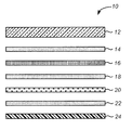
図1は、ガラス製のカバーシート12を含む従来の太陽光モジュール10の分解側断面図を示す。ガラスカバーシート12の隣に、(たとえば、多結晶シリコンまたは単結晶シリコンのいずれかで作製された)太陽電池16の両側を封入して「サンドイッチ様」構造を形成するために、封入材14および18が提供される。封入材18に隣接して、バックシートが配設される。バックシートは、単一または複数の層で構成されており、太陽光モジュールの長寿命化および安全性を保証するための複数の機能をはたす。図1には、1つのそのようなバックシート設計が示されており、このバックシートは、ラミネート接着材22によって互いに接合されたポリマー性誘電層20とポリマー性バックフィルム24とを含む。ポリマー性バックフィルム24は、水分、UVおよび機械的損傷に対する保護を提供する。誘電層20は、太陽光モジュールにアクセスする設置者、運搬担当者、メンテナンス担当者および消防士が電気ショックを受けないように、太陽光モジュール10の外側部分を太陽電池16から電気的に絶縁する。この安全フィーチャは、特に、高電圧システムの太陽光モジュールと接触する担当者には重要である。太陽光モジュール10は、アルミニウムフレーム(図を簡略化するために示されていない)によって取り囲まれており、アルミニウムフレームは、典型的には、構造一体性を提供し、ガラスカバーシート12の縁部を保護し、モジュールの設置および電気接地のための好都合な取付け点を提供する。太陽光モジュール10において、太陽電池16とアルミニウムフレームとの間に配設された層12、14、18、20、22および24は、集合的に、支持アセンブリを構成する。
FIG. 1 shows an exploded side sectional view of a conventional
従来のモジュールアセンブリにおいて、ガラスは、コスト効果的に、太陽光モジュールに構造的支持を提供し、運搬、設置、および使用中の損傷から太陽電池を保護し、また、湿気、雪、雹および飛散物のような環境要素から太陽電池を保護するので、カバーシート12の望ましい材料である。さらに、ガラスの高透過性により、太陽エネルギーが通過し、太陽電池に入射することが可能になり、電気を発生する。太陽エネルギーを最大化し、それを効果的に利用するために、封入材14および18は、太陽光波長を実質的に透過し、典型的には、モジュールを1つに接合するポリマー性接着材で作製される。図1に示し、上述したような太陽光モジュール10の構成および様々な構成要素は、太陽光モジュール設計の出現以来、変わっていない。
In conventional module assemblies, glass provides cost-effective structural support for solar modules, protects solar cells from damage during transportation, installation, and use, and also provides moisture, snow, hail and splashing. It is a desirable material for the
残念なことに、従来の太陽光モジュールは、必要な表面積および取得される電力を満たすために重くなり、したがって、いくつかの欠点に苦しんでいる。例として、従来のモジュールの重量および寸法により、その製造、梱包、運搬、設置および支持が困難になり、高価になる。従来の太陽光モジュールおよびアルミニウムの総重量は、約18kg〜約21kgである。そのサイズおよび厚さに応じて、(典型的には、重量が1モジュール当たり約12kg〜約15kgの)ガラスカバーシートは、モジュールの重さの大部分を占める。さらに、太陽光モジュールの厚さは、アルミニウムフレームを合わせると、約55mmとなる。さらに、ガラスカバーシートの脆弱な性質により、太陽光モジュール全体をしっかりと梱包することが必要になり、梱包の重量およびコストが増大する。 Unfortunately, conventional solar modules become heavier to meet the required surface area and acquired power and therefore suffer from several drawbacks. As an example, the weight and dimensions of conventional modules make their manufacture, packaging, transportation, installation and support difficult and expensive. The total weight of conventional solar modules and aluminum is about 18 kg to about 21 kg. Depending on its size and thickness, a glass cover sheet (typically about 12 kg to about 15 kg per module) occupies the majority of the module weight. Further, the thickness of the solar module is about 55 mm when the aluminum frame is combined. Furthermore, the fragile nature of the glass cover sheet requires that the entire solar module be securely packed, increasing the weight and cost of the packaging.
輸送に関すると、従来の太陽光モジュールの重量および厚さは、決まった体積の輸送コンテナで輸送され得るモジュールの量を制限する。その結果、多数のモジュールが必要とされる場合、出荷数が増加し、それにより、輸送コストが増大する。これらの輸送コストは、地方の仕向先で設置が行われるとき、または、運搬インフラが不十分である場合に、さらに悪化する。 When it comes to transport, the weight and thickness of conventional solar modules limit the amount of modules that can be transported in a fixed volume transport container. As a result, when a large number of modules are required, the number of shipments increases, thereby increasing transportation costs. These transportation costs are further exacerbated when installation is performed at a local destination or when the transportation infrastructure is inadequate.
設置に関すると、従来のモジュールの重量およびサイズは、住居規模の適用例、商業規模の適用例、および設備規模の適用例のための設置コストを増加させる。太陽光モジュールは、典型的には、建築物または地上構造物の屋上に設置される。設置の前に、各モジュールは、建築物の屋上まで持ち上げられ、次いで、所望のロケーションに置かれる。比較的重く大きいモジュールを扱うためには、そのような設置前のアクティビティーには、持ち上げ、操縦し、据え付けるために、2人以上の設置者が必要となる。いくつかの事例では、あまり一般的ではないモジュールを持ち上げるための追加の手段(たとえば、クレーンまたはリフト)が必要であり、それにより、設置コストが増大する。 With respect to installation, the weight and size of conventional modules increases installation costs for residential scale applications, commercial scale applications, and facility scale applications. Solar modules are typically installed on the rooftops of buildings or ground structures. Prior to installation, each module is lifted to the building roof and then placed in the desired location. In order to handle relatively heavy and large modules, such pre-installation activities require two or more installers to lift, maneuver and install. In some cases, additional means (eg, cranes or lifts) for lifting less common modules are required, thereby increasing installation costs.
また、設置には(「支持マウント」とも呼ばれる)サウンド構造支持システムが必要になるので、モジュールの重量は設置コストも増大させる。設置プロセス中、支持マウントは、建築物またはスタンドアロン施設に太陽光モジュールをしっかりとまたは堅固に接続するために使用される。さらに、支持マウントは、太陽光モジュールと太陽とを位置合わせしたまま保ち、強風または大雪のような悪天候の間にモジュールが損傷を受けることを防止する。苛酷な気象要素がない場合であっても、重い太陽光モジュール自体が、屋根および支持マウントに、大きな負荷をかける。その結果、支持マウントは、モジュールをしっかりと固定し、かつ、強風、地震および/または大雪により生じるさらなる負荷に耐えるように設計される。このために、地方、州および連邦の建築コードとエンジニアリング標準は、典型的には、採用した支持マウントが安全であり、意図通りに作動することを保証するために、採用した支持マウントを規制する。より重い太陽光モジュールは、典型的には、設計、構築および設置の費用が比較的高価なである、より強い支持マウントを必要とする。 Also, because the installation requires a sound structure support system (also referred to as a “support mount”), the weight of the module also increases installation costs. During the installation process, the support mount is used to securely or firmly connect the solar module to the building or stand-alone facility. Furthermore, the support mount keeps the solar module and the sun in alignment and prevents the module from being damaged during bad weather such as strong winds or heavy snow. Even in the absence of harsh weather elements, the heavy solar module itself places a heavy load on the roof and support mount. As a result, the support mount is designed to secure the module and to withstand further loads caused by strong winds, earthquakes and / or heavy snow. For this reason, local, state and federal building codes and engineering standards typically regulate adopted support mounts to ensure that the adopted support mounts are safe and operate as intended. . Heavier solar modules typically require stronger support mounts that are relatively expensive to design, build and install.
したがって、重い従来の太陽光モジュール設計が直面する欠点に苦しまない、新規の太陽光モジュールの設計およびその製造方法が必要とされる。 Therefore, there is a need for a new solar module design and method of manufacture that does not suffer from the disadvantages faced by heavy conventional solar module designs.
上記に鑑みて、本発明は、新規の、太陽電池支持層スタック設計、太陽モジュール設計、およびそれを生成するためのプロセスを提供する。1つの態様では、本発明は、太陽電池を機械的に支持するための太陽電池支持層スタックを提供する。本支持層スタックは、(i)剛性発泡層と、(ii)剛性発泡層に隣接して配設された1つまたは複数の外皮層とを含み、(iii)剛性発泡層ならびに外皮層のうちの1つまたは複数は、支持層スタックが太陽電池に隣接して配設されたときに、太陽電池に機械的支持を提供することが可能である。 In view of the above, the present invention provides a novel solar cell support layer stack design, solar module design, and a process for producing it. In one aspect, the present invention provides a solar cell support layer stack for mechanically supporting a solar cell. The support layer stack includes (i) a rigid foam layer and (ii) one or more skin layers disposed adjacent to the rigid foam layer, and (iii) of the rigid foam layer and the skin layer. One or more of the above may provide mechanical support to the solar cell when the support layer stack is disposed adjacent to the solar cell.
発明性のある支持層スタックの1つの実施形態において、剛性発泡層は、外皮層のうちの1つまたは複数の2つの間に挟まれ、外皮層のうちの1つは、支持スタック層が太陽電池に隣接して配設されたときに、剛性発泡層と太陽電池との間に配設される。支持層スタックは、外皮層と剛性発泡層のうちの1つまたは複数との間に配設された接着材層を含むことができる。剛性発泡層は、好ましくは、ポリエチレンテレフタラート、ポリウレタン、ポリエーテルイミド、ポリメタクリルイミド、スチレンアクリロニトリル、ポリイミド、ポリ塩化ビニル、ポリフッ化ビニリデン、ポリカーボネート、エチレン酢酸ビニル、バルサ材、ポリイソシアヌレート、ポリエチレン、カーボン、アルミニウム、ポリエチレンナフタレート、ポリオレフィン、およびポリプロピレンからなる群から選択される少なくとも1つの材料で作製される。本発明のより好ましい実施形態では、剛性の発泡体コアは、ポリエチレンテレフタラートで作製され得る。発泡層の厚さは、約3mm〜約25mmであり得る。本発明の1つの実施形によれば、剛性発泡層の密度は、約25kg/m3〜約300kg/m3である。 In one embodiment of the inventive support layer stack, the rigid foam layer is sandwiched between one or more of the outer skin layers, and one of the outer skin layers is a solar When disposed adjacent to the battery, it is disposed between the rigid foam layer and the solar cell. The support layer stack can include an adhesive layer disposed between the skin layer and one or more of the rigid foam layers. The rigid foam layer is preferably made of polyethylene terephthalate, polyurethane, polyetherimide, polymethacrylimide, styrene acrylonitrile, polyimide, polyvinyl chloride, polyvinylidene fluoride, polycarbonate, ethylene vinyl acetate, balsa material, polyisocyanurate, polyethylene, It is made of at least one material selected from the group consisting of carbon, aluminum, polyethylene naphthalate, polyolefin, and polypropylene. In a more preferred embodiment of the invention, the rigid foam core can be made of polyethylene terephthalate. The thickness of the foam layer can be from about 3 mm to about 25 mm. According to one embodiment of the present invention, the density of the rigid foam layer is from about 25 kg / m 3 to about 300 kg / m 3 .
本発明のある特定の実施形態では、剛性発泡層は、太陽電池を支持するのに十分な荷重支持特性を有し得る。例として、発泡層の圧縮強度は、約0.6MPa〜約7.5MPaである。別の例として、発泡層の圧縮弾性率は、約40MPa〜400MPaである。さらに別の例として、発泡層のせん断強度は、約0.4MPa〜4.5MPaである。さらに別の例として、発泡層のせん断弾性率は、約10MP〜約100MPaである。 In certain embodiments of the invention, the rigid foam layer may have sufficient load bearing properties to support the solar cell. As an example, the compressive strength of the foam layer is about 0.6 MPa to about 7.5 MPa. As another example, the compression elastic modulus of the foam layer is about 40 MPa to 400 MPa. As yet another example, the shear strength of the foam layer is about 0.4 MPa to 4.5 MPa. As yet another example, the shear modulus of the foam layer is from about 10 MP to about 100 MPa.
上述の1つまたは複数の外皮層は、好ましくは、ポリフッ化ビニル、テトラフルオロエチレンのポリマー、フッ化ヘキサフルオロプロピレン、フッ化ビニリデン、ポリフッ化ビニリデン、テトラフルオロエチレンコポリマー、エチレンクロロトリフルオロエチレン共重合体、ポリエチレンテレフタラート、ポリエチレンナフタレート、ポリアミド12、ポリアミド11、ポリメタクリル酸メチル、ポリカーボネート、ポリブチレンテレフタレート、アルミニウム、ステンレス鋼、亜鉛めっき鋼、チタン、銅、モリブデン、ガラス繊維含有ポリエチレン樹脂、およびガラス繊維含有ポリプロピレン樹脂からなる群から選択される少なくとも1つの材料で作製される。ただし、本発明のより好ましい実施形態では、外皮層のうちの1つまたは複数はアルミニウム製である。本発明の代替的なより好ましい実施形態では、外皮層のうちの1つまたは複数はステンレス鋼製である。
The one or more skin layers described above are preferably made of polyvinyl fluoride, polymer of tetrafluoroethylene, hexafluoropropylene fluoride, vinylidene fluoride, polyvinylidene fluoride, tetrafluoroethylene copolymer, ethylene chlorotrifluoroethylene copolymer Polymer, polyethylene terephthalate, polyethylene naphthalate,
本発明の1つの実施形態では、外皮層のうちの1つまたは複数の厚さは、約0.025mm〜約3.0mmである。好ましくは、外皮層のうちの1つまたは複数は、支持層スタックが太陽電池に隣接して配置されたときに支持層スタックを太陽電池から電気的に絶縁する絶縁層である。1つまたは複数の外皮層のうちの少なくとも1つは、太陽光UVエネルギーに対して耐性があり得る。さらに、1つまたは複数の外皮層のうちの少なくとも1つの透湿度は、0.05GM/m2/日未満であり得る。 In one embodiment of the invention, the thickness of one or more of the outer skin layers is from about 0.025 mm to about 3.0 mm. Preferably, one or more of the skin layers are insulating layers that electrically insulate the support layer stack from the solar cell when the support layer stack is disposed adjacent to the solar cell. At least one of the one or more skin layers may be resistant to solar UV energy. Further, the water vapor transmission rate of at least one of the one or more skin layers may be less than 0.05 GM / m 2 / day.
発明性のある支持スタック層は、外皮層のうちの1つまたは複数と剛性の発泡体コアとの間に配設された接着材層を含み得る。ただし、本発明の代替実施形態では、支持層スタックを形成するために、接着剤を使用せずに、発泡層を外皮層のうちの1つまたは複数と融合させることができる。 The inventive support stack layer may include an adhesive layer disposed between one or more of the skin layers and the rigid foam core. However, in an alternative embodiment of the present invention, the foam layer can be fused with one or more of the skin layers without the use of an adhesive to form a support layer stack.
別の態様では、本発明は、太陽光モジュールを提供する。本太陽光モジュールは、(i)太陽電池と、(ii)太陽電池に隣接し、太陽電池を機械的に支持する太陽電池支持層スタックとを含む。この態様では、太陽電池支持層スタックは、(i)剛性発泡層、ならびに(ii)剛性発泡層に隣接して配設された1つまたは複数の外皮層を含み、(iii)剛性発泡層ならびに1つまたは複数の外皮層は、支持層スタックが太陽電池に隣接して配設されたときに、太陽電池に機械的支持を提供することが可能である。 In another aspect, the present invention provides a solar module. The solar module includes (i) a solar cell and (ii) a solar cell support layer stack adjacent to the solar cell and mechanically supporting the solar cell. In this aspect, the solar cell support layer stack includes (i) a rigid foam layer, and (ii) one or more skin layers disposed adjacent to the rigid foam layer, and (iii) a rigid foam layer and One or more skin layers may provide mechanical support to the solar cell when the support layer stack is disposed adjacent to the solar cell.
発明性のある太陽光モジュールの幅は約0.5m〜約3.0mであり得、長さは約0.5m〜約3.0mであり得、厚さが約4.0mm〜約25mmであり得る。本太陽光モジュールの重量は約4.0kg〜約10.0kgであり得る。 Inventive solar modules may have a width of about 0.5 m to about 3.0 m, a length of about 0.5 m to about 3.0 m, and a thickness of about 4.0 mm to about 25 mm. possible. The solar module may have a weight of about 4.0 kg to about 10.0 kg.
本太陽光モジュールの内部にある太陽電池は、好ましくは、多結晶シリコン、単結晶シリコン、テルル化カドミウム、銅インジウムガリウムジセレニド、非晶質の単接合シリコン、非晶質および多結晶の二重接合シリコーン、結晶シリコーン、ガリウムひ素、ならびに銅亜鉛スズ硫化物からなる群から選択される少なくとも1つの材料を含む。 The solar cell inside this solar module is preferably polycrystalline silicon, single crystal silicon, cadmium telluride, copper indium gallium diselenide, amorphous single junction silicon, amorphous and polycrystalline At least one material selected from the group consisting of heavy bonded silicone, crystalline silicone, gallium arsenide, and copper zinc tin sulfide.
さらに別の態様では、本発明は、太陽電池支持層スタックを製造するためのプロセスを提供する。本プロセスは、(i)剛性発泡層を取得することと、(ii)剛性発泡層に隣接して配設された1つまたは複数の外皮層を取得することであって、剛性発泡層ならびに1つまたは複数の外皮層は、支持層スタックが太陽電池に隣接して配設されたときに、太陽電池に機械的支持を提供することが可能である、1つまたは複数の外皮層を取得することと、(iii)太陽電池支持層スタックを形成するために、剛性発泡層と外皮層のうちの1つまたは複数との間に接着剤を塗布することとを含む。 In yet another aspect, the present invention provides a process for manufacturing a solar cell support layer stack. The process includes: (i) obtaining a rigid foam layer; and (ii) obtaining one or more skin layers disposed adjacent to the rigid foam layer, wherein the rigid foam layer and 1 The one or more skin layers obtain one or more skin layers that can provide mechanical support to the solar cell when the support layer stack is disposed adjacent to the solar cell. And (iii) applying an adhesive between the rigid foam layer and one or more of the skin layers to form a solar cell support layer stack.
剛性発泡層と外皮層のうちの1つまたは複数との間に塗布される接着剤は、好ましくは、エチレン酢酸ビニル、ポリウレタン、シリコーン、ポリビニルブチラール、ポリオレフィン、イオノマー、エポキシ類、ブチルゴム系接着剤、およびビニルフェノールからなる群から選択される1つの材料を含む。 The adhesive applied between the rigid foam layer and one or more of the skin layers is preferably ethylene vinyl acetate, polyurethane, silicone, polyvinyl butyral, polyolefin, ionomer, epoxy, butyl rubber adhesive, And one material selected from the group consisting of vinylphenol.
さらに別の態様では、本発明は、太陽電池支持層スタックを製造するための別のプロセスを提供する。本プロセスは、(i)剛性発泡層を取得することと、(ii)剛性発泡層に隣接して配設された1つまたは複数の外皮層を取得することであって、剛性発泡層ならびに1つまたは複数の外皮層は、支持層スタックが太陽電池に隣接して配設されたときに、太陽電池に機械的支持を提供することが可能である、1つまたは複数の外皮層を取得することと、(iii)加熱された剛性発泡層ならびに1つまたは複数の加熱された外皮層を形成するために、剛性発泡層あるいは外皮層のうちの1つまたは複数を、剛性発泡層あるいは1つまたは複数の外皮層の少なくとも1つの融点または実質的にその近くまで加熱することと、加熱された剛性発泡層と1つまたは複数の加熱された外皮層とを接合し、太陽電池支持層スタックを形成するために圧力を印加することとを含む。 In yet another aspect, the present invention provides another process for manufacturing a solar cell support layer stack. The process includes: (i) obtaining a rigid foam layer; and (ii) obtaining one or more skin layers disposed adjacent to the rigid foam layer, wherein the rigid foam layer and 1 The one or more skin layers obtain one or more skin layers that can provide mechanical support to the solar cell when the support layer stack is disposed adjacent to the solar cell. And (iii) one or more of the rigid foam layer or skin layer is replaced with a rigid foam layer or one to form a heated rigid foam layer and one or more heated skin layers. Or heating at least one melting point or substantially close to the plurality of skin layers, joining the heated rigid foam layer and one or more heated skin layers, and Pressure to form And a be applied to.
本発明の1つの実施形態によれば、剛性発泡層の融点は、約l60℃〜約275℃である。外皮層のうちの1つまたは複数の融点は、約200℃〜約240℃である。加熱することは、真空バッグと連動する従来のサーマル炉、ピンチローラーを伴う赤外炉、マイクロ波加熱炉プレス、火炎処理、加熱ピンチローラー、油圧加熱プレス、オートクレーブ、加熱真空バッグ、ならびに連続する加熱された金属ベルトをもつ平台ラミネータのうちの少なくとも1つを使用する熱処理を行うことを含む。加熱された剛性発泡層と1つまたは複数の加熱された外皮層とを接合するために印加された圧力は、好ましくは、約10lbs/in2〜約50lbs/in2の圧力である。1つの実施形態では、発明性のあるプロセスは、15分未満の持続時間にわたって圧力を印加する。発明性のある、支持層スタックを製造するプロセスは、冷却された太陽電池支持層スタックを形成するために、圧力の印加に太陽電池支持層スタックを冷却することをさらに含む。本発明の1つの実施形態によって企図される冷却の持続時間は、15分未満であり得る。 According to one embodiment of the present invention, the rigid foam layer has a melting point of about 160 ° C. to about 275 ° C. The melting point of one or more of the outer skin layers is from about 200 ° C to about 240 ° C. Heating is a conventional thermal furnace working with a vacuum bag, an infrared furnace with a pinch roller, a microwave heating furnace press, flame treatment, a heating pinch roller, a hydraulic heating press, an autoclave, a heating vacuum bag, and continuous heating Performing a heat treatment using at least one of a flatbed laminator having a formed metal belt. The pressure applied to join the heated rigid foam layer and the one or more heated skin layers is preferably a pressure of about 10 lbs / in 2 to about 50 lbs / in 2 . In one embodiment, the inventive process applies pressure for a duration of less than 15 minutes. The inventive process of manufacturing the support layer stack further includes cooling the solar cell support layer stack to the application of pressure to form a cooled solar cell support layer stack. The duration of cooling contemplated by one embodiment of the present invention may be less than 15 minutes.
さらに別の態様では、本発明は、太陽光モジュールを製造するプロセスを提供する。太陽光モジュールを製造するプロセスは、(i)太陽電池を取得することと、(ii)太陽電池支持層スタックを取得することであって、太陽電池支持層スタックが、(a)剛性発泡層、ならびに(b)剛性発泡層に隣接して配設された1つまたは複数の外皮層を含み、(c)剛性発泡層ならびに外皮層のうちの1つまたは複数は、支持層スタックが太陽電池に隣接して配設されたときに、太陽電池に機械的支持を提供することが可能である、太陽電池支持層スタックを取得することと、(iii)太陽光モジュールを形成するために、前記太陽電池と前記太陽電池支持層スタックとの間に接着剤を塗布することとを含む。 In yet another aspect, the present invention provides a process for manufacturing a solar module. The process of manufacturing a solar module is (i) obtaining a solar cell and (ii) obtaining a solar cell support layer stack, wherein the solar cell support layer stack is (a) a rigid foam layer, And (b) one or more skin layers disposed adjacent to the rigid foam layer, and (c) one or more of the rigid foam layer and the skin layer are provided with a support layer stack on the solar cell. Obtaining a solar cell support layer stack capable of providing mechanical support to the solar cells when disposed adjacent to each other; and (iii) forming the solar module to form the solar module Applying an adhesive between the battery and the solar cell support layer stack.
ただし、本発明の構成および動作方法は、特定の実施形態に関する以下の記載を添付の図面と関連付けて読むと、その追加の目的および利点とともに、最もよく理解されるであろう。 However, the structure and method of operation of the present invention, together with its additional objects and advantages, will be best understood when the following description of the specific embodiments is read in conjunction with the accompanying drawings.
以下の記載において、本発明の完全な理解を与えるために、多数の具体的な詳細について説明する。ただし、本発明がこれらの具体的な詳細のいくつかのまたは全部に限定することなく実施され得ることは、当業者には明らかであろう。他の例では、本発明を理解するうえで不要な混乱を避けるために、周知の工程ステップについては詳述されていない。 In the following description, numerous specific details are set forth in order to provide a thorough understanding of the present invention. However, it will be apparent to those skilled in the art that the present invention may be practiced without limiting to some or all of these specific details. In other instances, well known process steps have not been described in detail in order to avoid unnecessarily confusing in understanding the present invention.
本発明は、ガラスカバーシートを含まない太陽電池支持層スタックが、従来の太陽光モジュール設計が直面する欠点を克服することを明らかにする。本発明の1つの実施形態によれば、支持層スタックは、従来のアセンブリでは紫外線、湿気、雪、雹および飛散物のような環境要素に対する抵抗性を有するように設計される、ガラス製ではないカバーシートを含む。好ましい実施形態では、発明性のある支持層スタックは、適切な外皮層に隣接または近接する任意の剛性層を含む。ただし、より好ましい実施形態では、発明性のある剛性層は、発泡層で構成される。 The present invention demonstrates that a solar cell support layer stack that does not include a glass cover sheet overcomes the disadvantages faced by conventional solar module designs. According to one embodiment of the present invention, the support layer stack is not made of glass, which is designed to be resistant to environmental elements such as ultraviolet light, moisture, snow, hail and flying objects in conventional assemblies. Includes cover sheet. In a preferred embodiment, the inventive support layer stack includes any rigid layer adjacent or adjacent to a suitable skin layer. However, in a more preferred embodiment, the inventive rigid layer is composed of a foam layer.
本明細書で使用される場合「隣接する」という用語は、「隣接する」と特徴づけられており、太陽光モジュールまたは太陽電池支持層スタックの内側に配設された別々の層が互いに接触している実施形態には限定されないことに留意されたい。「隣接する」という用語の使用は、むしろ、1つまたは複数の中間層が2つの「隣接する」層の間に介挿されるような実施形態も包含する。 As used herein, the term “adjacent” is characterized as “adjacent” and separate layers disposed inside a solar module or solar cell support layer stack contact each other. It should be noted that the embodiments are not limited. Rather, the use of the term “adjacent” also encompasses embodiments in which one or more intermediate layers are interposed between two “adjacent” layers.
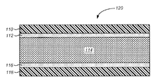
図2は、典型的には接着材層によって1つまたは複数の太陽電池に付着する例示的な発明性のある支持層スタック120を示す。支持層スタック120は、介挿された接着材層112および116を使用して2つの外皮層110および118の間に挟まれた剛性発泡層114を含む。発泡層114は、支持層120を太陽光モジュール内の太陽電池と組み付けたときに、太陽電池に機械的支持を提供する。発泡層114の機械的特性の例として、せん断強度、せん断弾性率、せん断伸長度、圧縮強度、圧縮弾性率、衝撃靭性(すなわち、弾力性)および耐疲労性が挙げられる。
FIG. 2 illustrates an exemplary inventive
外皮層110および118は、発泡体構成要素および太陽光モジュール全体に対する他の主要な環境保護特性とともに、引張強度、引張弾性率、圧縮強度、圧縮弾性率を提供することができる。外皮層110は、太陽光モジュール内で太陽電池を外皮層110の外部の構成要素から電気的に絶縁する誘電層としての機能することができる。外皮層118は、好ましくは、湿気、紫外線、雪、雹および飛散物のような環境要素からの発泡層114および太陽電池に対する保護を提供する。
The skin layers 110 and 118 can provide tensile strength, tensile modulus, compressive strength, compressive modulus, along with other major environmental protection properties for the foam component and the overall solar module. The
接着材層112および116は、好ましくは、太陽光モジュールの寿命のために、外皮とコアとの間のせん断力および引張力に耐えることができると同時に、これらのエレメントを1つに接合する本質的役割をはたすことができる。
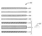
図3は、本発明の1つの実施形態による太陽光モジュール200を示す。太陽光モジュール200は、図2に示した支持層スタック120と実質的に同様の支持層スタック220を組み込んでいる。太陽光モジュール200は、介挿された接着材層204によって互いに接着したカバーフィルム202と、太陽電池206とを含む。カバーフィルム202と接着材層204と太陽電池206とのサブアセンブリは、別の接着材層208によって支持層スタック220に接着する。この構成では、接着材層204と接着材層208とが太陽電池206を挟んでいることに留意されたい。本発明の好ましい実施形態では、接着材層204および208は、太陽電池206を封入しており、したがって、一般的には「封入材」と呼ばれる。封入材204および208によって、知られていることもあるように、太陽光モジュールに作用する外力から、太陽電池がさらに保護される。封入材208に隣接して、支持層スタックが図2に記載したように配設される。図3に示した実施形態では、支持層スタック220は、発泡層214を挟んでいる2つの外皮層210および218を含む。外皮層210と発泡層214との間に介挿された接着剤212と、発泡層214と外皮層218との間に介挿された接着剤216とは、太陽光モジュール200の寿命および動作中に、支持層スタックサブアセンブリ220を一緒に保持する。
FIG. 3 illustrates a
本発明のある特定の好ましい実施形態では、発明性のある支持層スタックサブアセンブリ中に図2および図3に示すような2つ以上の外皮層を有する必要はない。図4は、単一の外皮層を有する支持層スタックを含む、本発明の別の実施形態による太陽光モジュール300を示す。
In certain preferred embodiments of the invention, it is not necessary to have more than one skin layer as shown in FIGS. 2 and 3 in the inventive support layer stack subassembly. FIG. 4 illustrates a
太陽光モジュール300は、カバーフィルム302、封入材304および308、ならびに太陽電池306を含むが、これらは、図3に示したそれらの相対物、すなわち、カバーフィルム202、封入材204および208、ならびに太陽電池206と同じまたは実質的に同様である。さらに、外皮層318、接着材層316および発泡層314もまた、図3に示したそれらの相対物、すなわち、外皮層318、接着材層316および発泡層314と同じまたは実質的に同様である。図4に示した実施形態では、外皮層210および接着材層212に対応する層がないことに留意されたい。外皮層と、関連する接着材層とがないことにより、最終的に生成される太陽光モジュール300の重量が低減され、製造コストが下がるという利点を享受する、発明性のある支持層スタックが提供される。
The
ただし、本発明のある特定の好ましい実施形態では、発明性のある支持層スタックサブアセンブリを一緒に保持するために、接着材層(たとえば、図3の接着材層212および216)が必ずしも必要ではないことに留意することもまた重要である。このために、図5は、任意の接着材層を使用せずに、外皮層410と外皮層418との間に直接挟まれた発泡層414を含む、本発明の代替実施形態による太陽光モジュール400を示している。すべての他の点において、図5の太陽光モジュール400は、図3の太陽光モジュール200と実質的に同様である。換言すると、カバーフィルム402、封入材404および408、ならびに太陽電池406は、図3のそれらの相対物、すなわち、カバーフィルム202、封入材204および208、ならびに太陽電池206と同じまたは実質的に同様である。
However, in certain preferred embodiments of the present invention, an adhesive layer (eg,
接着材層がない場合、図5の得られた支持層スタック420は、比較的軽量であり、安価に製造することができ、支持層スタックまたは太陽光モジュールの製造プロセス中に必要な材料が少なくなる。支持層スタック内の異なる層同士の間に高い接合強度を必要とするような適用例では、支持層スタック120は、本発明の好ましい実施形態を提示し得る。
In the absence of an adhesive layer, the resulting support layer stack 420 of FIG. 5 is relatively lightweight and can be manufactured inexpensively and requires less material during the manufacturing process of the support layer stack or solar module. Become. In applications that require high bond strength between different layers in the support layer stack, the
本発明が企図するような発泡層(たとえば、図2の114、図3の214、図4の314、図5の414)は、発泡体で作製する必要はなく、太陽光モジュール内で太陽電池に対する機械的支持を提供することが可能な任意の好適な剛性かつ軽量の材料でも同様に作製される。ただし、発泡層は、ポリエチレンテレフタレート、ポリウレタン、ポリエーテルイミド、ポリメタクリルイミド、スチレンアクリロニトリル、ポリイミド、ポリ塩化ビニル、ポリフッ化ビニリデン、ポリカーボネート、エチレン酢酸ビニル、バルサ材、ポリイソシアヌレート、ポリエチレン、カーボン、アルミニウム、ポリエチレンナフタレート、ポリオレフィン、およびポリプロピレンからなる群から選択される少なくとも1つの材料で作製されることが好ましい。 The foamed layer as contemplated by the present invention (eg, 114 in FIG. 2, 214 in FIG. 3, 314 in FIG. 4, 414 in FIG. 5) need not be made of foam, and the solar cell within the solar module. Any suitable rigid and lightweight material capable of providing mechanical support for is similarly produced. However, the foam layer is made of polyethylene terephthalate, polyurethane, polyetherimide, polymethacrylimide, styrene acrylonitrile, polyimide, polyvinyl chloride, polyvinylidene fluoride, polycarbonate, ethylene vinyl acetate, balsa material, polyisocyanurate, polyethylene, carbon, aluminum Preferably, it is made of at least one material selected from the group consisting of polyethylene naphthalate, polyolefin, and polypropylene.
発明性のある支持層スタック内の発泡層は、太陽光モジュール内で太陽電池に必要な機械的支持を提供する好適な厚さのものとすることができる。本発明の1つの実施形態によれば、発明性のある支持層スタックの内側の発泡層の厚さは、約3mm〜約25mmである。ただし、本発明の好ましい実施形態では、発泡層の厚さは、約4mm〜約12mmである。同様に、本発明のより好ましい実施形態では、発泡層の厚さは、約5mm〜約10mmである。 The foam layer in the inventive support layer stack can be of a suitable thickness that provides the necessary mechanical support for the solar cell within the solar module. According to one embodiment of the invention, the thickness of the foam layer inside the inventive support layer stack is from about 3 mm to about 25 mm. However, in a preferred embodiment of the present invention, the thickness of the foam layer is from about 4 mm to about 12 mm. Similarly, in a more preferred embodiment of the present invention, the thickness of the foam layer is from about 5 mm to about 10 mm.
発明性のある支持層スタックの発泡層の密度は、過度な外力がある場合にはその外力に耐えるために必要な強度を太陽光モジュールに提供する任意の値とすることができる。発泡層密度は、約25kg/m3〜約300kg/m3の値とすることができ、より好ましくは約75kg/m3〜約250kg/m3の値であり、最も好ましくは約100kg/m3〜約200kg/m3の値である。 The density of the foam layer of the inventive support layer stack can be any value that provides the solar module with the strength needed to withstand the external force if there is an excessive external force. The foam layer density can be a value of about 25 kg / m 3 to about 300 kg / m 3 , more preferably a value of about 75 kg / m 3 to about 250 kg / m 3 , most preferably about 100 kg / m 3. 3 to about 200 kg / m 3 .
本発明のある特定の実施形態では、太陽光モジュールが適用時に受ける静的な力および動的力に対処するために必要な剛性およびせん断強度を提供することができる十分な荷重支持特性を有する発泡層を有することが望ましい。このために、発明性のある支持層スタックの発泡層の圧縮強度値の測定値は当業者に適切であると見なされ得る。この値が適切であると見なされるような事例では、発明性のある発泡層の圧縮強度値は、好ましくは約0.6MPa〜約7.MPaであり、より好ましくは約1.0MPa〜約3.5MPaであり、最も好ましくは約1.4MPa〜約2.5MPaである。他の事例では、当業者は、圧縮弾性率値を発泡層強度の重要な測度と見なし得る。そのような場合、発明性のある発泡層の圧縮弾性率値は、約40MPa〜約400MPaであり、好ましくは約75MPa〜約200MPaであり、より好ましくは約100MPa〜約180MPaである。 In certain embodiments of the present invention, foam with sufficient load bearing properties that can provide the necessary stiffness and shear strength to cope with the static and dynamic forces that the solar module experiences during application. It is desirable to have a layer. For this reason, the measurement of the compressive strength value of the foam layer of the inventive support layer stack can be regarded as appropriate to the person skilled in the art. In cases where this value is deemed appropriate, the compressive strength value of the inventive foamed layer is preferably from about 0.6 MPa to about 7. MPa, more preferably from about 1.0 MPa to about 3.5 MPa, and most preferably from about 1.4 MPa to about 2.5 MPa. In other cases, one skilled in the art may consider the compression modulus value as an important measure of foam layer strength. In such a case, the compressive modulus value of the inventive foamed layer is from about 40 MPa to about 400 MPa, preferably from about 75 MPa to about 200 MPa, more preferably from about 100 MPa to about 180 MPa.
発明性のある発泡層のせん断強度値に関すると、許容範囲は、約0.4MPa〜約4.5MPaである。ただし、好ましくは、せん断強度値は約0.6MPa〜約3.0MPaであり、より好ましくは約0.8MPA〜約1.6MPaである。発明性のある発泡層に関連するせん断弾性率値またはせん断強度値が適切であると見なされる限り、本発明では、比較的広範囲の測定値が企図される。例として、発明性のある発泡層のせん断弾性率値は、約10MPa〜約100MPaであり、好ましくは約20MPa〜約75MPaであり、より好ましくは約30MPa〜約60MPaである。 Regarding the shear strength value of the inventive foamed layer, the acceptable range is from about 0.4 MPa to about 4.5 MPa. However, preferably, the shear strength value is about 0.6 MPa to about 3.0 MPa, more preferably about 0.8 MPa to about 1.6 MPa. As long as the shear modulus value or shear strength value associated with the inventive foamed layer is deemed appropriate, a relatively broad range of measurements is contemplated by the present invention. By way of example, the inventive shear layer has a shear modulus value of about 10 MPa to about 100 MPa, preferably about 20 MPa to about 75 MPa, more preferably about 30 MPa to about 60 MPa.
外皮層は、支持層スタックに機械的強度を提供することに加えて、またはその代わりに、環境要素から太陽電池を保護するのに役立ち得る。本発明のある特定の他の実施形態では、外皮層は、支持層スタックサブアセンブリに絶縁耐力を提供する。外皮層を形成することのために使用される代表的な材料は、ポリフッ化ビニル、テトラフルオロエチレンのポリマー、フッ化ヘキサフルオロプロピレン、フッ化ビニリデン、ポリフッ化ビニリデン、テトラフルオロエチレンコポリマー、エチレンクロロトリフルオロエチレン共重合体、ポリエチレンテレフタレート、ポリエチレンナフタレート、ポリアミド12、ポリアミド11、ポリメタクリル酸メチル、ポリカーボネート、ポリブチレンテレフタレート、アルミニウム、ステンレス鋼、亜鉛めっき鋼、チタン、銅、モリブデン、ガラス繊維含有ポリエチレン樹脂、およびガラス繊維含有ポリプロピレン樹脂からなる群から選択される少なくとも1つの材料を含む。
The skin layer can help protect the solar cell from environmental elements in addition to or instead of providing mechanical strength to the support layer stack. In certain other embodiments of the invention, the skin layer provides dielectric strength to the support layer stack subassembly. Typical materials used to form the skin layers are polyvinyl fluoride, tetrafluoroethylene polymer, hexafluoropropylene fluoride, vinylidene fluoride, polyvinylidene fluoride, tetrafluoroethylene copolymer, ethylene chlorotriethylene. Fluoroethylene copolymer, polyethylene terephthalate, polyethylene naphthalate,
発明性のある支持層スタックでは、様々な物理的特性または化学的特性を有する外皮層は、広範囲の環境要素からの保護を提供する。重要な特性の例として、機械的強度、耐UV性、熱的安定度、加水分解安定性、引火性、酸素透過率、および透湿度が挙げられる。適切な厚さの発泡層に加えて、適切な厚さの外皮層もまた、太陽光モジュール内で太陽電池を支持する、発明性のある支持層スタックの機械的強度に寄与する。1つまたは複数の外皮層の厚さは、本発明の1つの実施形態によれば、発明性のある支持層スタックにおいて約0.025mm〜約3.0mmであり、好ましくは約0.100mm〜約1.0mmであり、最も好ましくは約0.175mm〜約0.500mmである。 In inventive support layer stacks, skin layers with various physical or chemical properties provide protection from a wide range of environmental elements. Examples of important properties include mechanical strength, UV resistance, thermal stability, hydrolytic stability, flammability, oxygen permeability, and moisture permeability. In addition to the appropriate thickness of the foam layer, the appropriate thickness of the skin layer also contributes to the mechanical strength of the inventive support layer stack that supports the solar cells within the solar module. The thickness of the one or more skin layers is, according to one embodiment of the invention, from about 0.025 mm to about 3.0 mm in an inventive support layer stack, preferably from about 0.100 mm to About 1.0 mm, most preferably about 0.175 mm to about 0.500 mm.
長期間にわたってUV照射に曝されると、ポリマーの物理的特性および光学的性質が劣化する。したがって、発明性のある支持層スタックが、そのような照射に対する耐性を維持し、提供することが望ましい。このために、発明性のある支持層スタックの1つまたは複数の外皮層は、好ましくは、300〜400nm波長のUV照射に対して100%不透過性であり、間欠的に水を噴霧しながら42℃〜63℃の温度で0.35ワット/m2のUV照射に10,000時間曝露した後、それらの元の機械的特性および光学的特性の80%以上を維持する。外皮層を通って浸透する水蒸気は、太陽電池、発泡体および封入材の性能および寿命に影響を及ぼし得、好ましくは、太陽光モジュール全体に使用される材料の長寿命および高性能を可能にするレベルまで低減される。本発明の発明性のある支持層スタックの外皮層の耐透湿性の値は約0.05gm/m2/日未満であり得、は、より好ましくは約0.005gm/m2/日未満の値であり、最も好ましくは約0.0005gm/m2/日未満の値である。 When exposed to UV radiation for extended periods, the physical and optical properties of the polymer degrade. Accordingly, it is desirable for an inventive support layer stack to maintain and provide resistance to such irradiation. For this purpose, one or more skin layers of the inventive support layer stack are preferably 100% impervious to 300-400 nm wavelength UV radiation, while spraying water intermittently. Maintain over 80% of their original mechanical and optical properties after 10,000 hours exposure to 0.35 Watt / m 2 UV radiation at a temperature of 42 ° C. to 63 ° C. Water vapor that permeates through the skin layer can affect the performance and lifetime of solar cells, foams and encapsulants, preferably allowing for long life and high performance of materials used throughout solar modules. Reduced to level. The moisture resistance value of the skin layer of the inventive support layer stack of the present invention may be less than about 0.05 gm / m 2 / day, more preferably less than about 0.005 gm / m 2 / day. Value, most preferably less than about 0.0005 gm / m 2 / day.
1つまたは複数の外皮層が支持層スタックサブアセンブリに絶縁耐力を提供するような実施形態では、各外皮層の絶縁耐力は、約750ボルト〜約1,200ボルトである部分放電電圧レベルを生じるのに十分な高さである。本発明の1つの好適な実施形態では、アルミニウムまたは別の導電性金属を含む1つの外皮層が、太陽電池から最も遠くに配設され(たとえば、図2の外皮層118)、環境要素からの保護を提供するように設計される。この実施形態では、必要な絶縁耐力を提供するために、ポリエステルおよび金属を含む別の外皮層(たとえば、図2の外皮層110)が太陽電池に近接して配設される。
In embodiments where one or more skin layers provide dielectric strength to the support layer stack subassembly, the dielectric strength of each skin layer results in a partial discharge voltage level that is between about 750 volts and about 1,200 volts. It is high enough. In one preferred embodiment of the invention, one skin layer comprising aluminum or another conductive metal is disposed furthest from the solar cell (eg,
接着材層(たとえば、図2の接着材層112および116)を発泡層と1つまたは複数の外皮層との間に配設して2つの層を接合するような、発明性のある支持層スタックの実施形態(たとえば、図2、図3および図4)では、接着材層は、接合機能を効果的にはたす任意の効果的な接着剤を含み得る。本発明の1つの実施形態では、接着材層は、エチレン酢酸ビニル、ポリウレタン、シリコーン、ポリビニルブチラール、ポリオレフィン、イオノマー、エポキシ類、ブチルゴム系接着剤、およびビニルフェノールからなる群から選択される材料を含む。そのような接着材層は、いくつかの事例では、接着材層に強度を与える充填材料を含み得る。そのような充填材料は、たとえば、グラススフィアー、シリカおよびナノ結晶セルロースを含む。
Inventive support layer in which an adhesive layer (eg,
発明性のある支持層スタックは、太陽電池の特定のタイプとの使用に限定されない。発明性のある支持層スタックは、むしろ、太陽光モジュールの多種多様な太陽電池とともに利用することができる。代表的な太陽電池は、多結晶シリコン、単結晶シリコン、テルル化カドミウム、銅インジウムガリウムジセレニド、非晶質の単接合シリコン、非晶質および多結晶の二重接合シリコーン、結晶シリコン、ガリウムひ素、ならびに銅亜鉛スズ硫化物を含む。 Inventive support layer stacks are not limited to use with a particular type of solar cell. Rather, the inventive support layer stack can be utilized with a wide variety of solar cells in solar modules. Typical solar cells are polycrystalline silicon, single crystal silicon, cadmium telluride, copper indium gallium diselenide, amorphous single junction silicon, amorphous and polycrystalline double junction silicone, crystalline silicon, gallium Contains arsenic, as well as copper zinc tin sulfide.
本発明はまた、発明性のある支持層スタック、ならびに当該支持層スタック(たとえば、図2の支持層スタック120、図3の支持層スタック220、および図4の支持層スタック320のうちの1つ)を組み込んだ発明性のある太陽光モジュールを製造するための新規のプロセスを提供する。図6は、支持層スタック(たとえば、図2の支持層スタック120、図3の支持層スタック220、および図4の支持層スタック320のうちの1つ)を製造するための、本発明の1つの実施形態によるプロセス500のフローチャートを示す。プロセス500は、好ましくは、剛性発泡層(たとえば、図2の発泡層114、図3の発泡層214、および図4の発泡層314のうちの1つ)を取得することを含むステップ502から始まる。上述のように、発泡層は、1つまたは複数の太陽電池を機械的に支持することが可能である。
The present invention also provides an inventive support layer stack and one of the support layer stacks (eg,
次に、ステップ504は、1つまたは複数の外皮層(たとえば、図2の外皮層110および118、図3の外皮層210および218、ならびに図4の外皮層318のうちの1つ)を取得することを含む。図6を続けて参照すると、ステップ506において、発明性のある層スタックを形成するために、発泡層と外皮層のうちの1つまたは複数との間に、接着剤(たとえば、図2の接着材層112および116、図3の接着材層212および216、ならびに図4の接着材層316のうちの少なくとも1つであり、個別層の形態とすることができる)を塗布する。図6のステップ504は、少なくとも1つの外皮層が湿気または熱エネルギーに対して実質的に不浸透性であることを必要とするが、本発明はそれに限定されるものではない。本発明の外皮層は、任意の特定の特性に限定されるものではなく、本明細書に記載される様々な特性のうちのいずれか1つまたは組合せを有し得る。
Next,
当業者には、ステップ502、504および506を任意の特定の順序で実行しなくてもよいこと、ならびに、図5に提示したステップのシーケンスは、発明性のある支持層スタックを組み付ける1つの例示的なシーケンスであることが認識されるであろう。例として、ステップ502の後、ステップ506を実行し、その上の接着剤を用いて発泡層を生成する。次に、ステップ504を実装して、発泡層に外皮層を付着させ、発明性のある支持層スタックを形成する。
Those skilled in the art will not need to perform
発明性のあるプロセスは特定のシーケンスに限定されるだけでなく、図5の発明性のある支持層スタックに示すような接着材層を使用することによって接着の効果を奏することにも限定されない。このために、本発明は、支持層スタック(たとえば、図5の支持層スタック420)を製造するための、本発明の別の実施形態によるプロセス600を提供する。プロセス600は、好ましくは、剛性発泡層を取得することを含むステップ602で開始する。ステップ602は、図5のステップ502と同じまたは実質的に同様である。次に、プロセス600は、1つまたは複数の外皮層を取得することを含むステップ604に進むが、このステップ604は、図5のステップ504と同じまたはと実質的に同様である。
The inventive process is not limited to a specific sequence, but is also not limited to exerting an adhesive effect by using an adhesive layer as shown in the inventive support layer stack of FIG. To this end, the present invention provides a
次いで、ステップ606を実行する。ステップ606は、加熱された発泡層および/または少なくとも1つの加熱された外皮層を生成するために、発泡層および/または外皮層のうちの1つまたは複数を、発泡層または外皮層のいずれか1つの融点または実質的にその近くまで加熱することを含む。
Next,
ステップ606において、発泡体と(1つまたは複数の)外皮層との間に効果的な接合を可能にする程度まで加熱された層のうちのいずれか1つが溶融する限り、加熱された層のどれが溶融するかは問題ではない。本発明の1つの実施形態では、発泡体コアならびに/あるいは1つまたは複数の外皮層を約200℃の温度まで加熱する。ただし、発泡体ならびに/あるいは外皮層のうちの1つまたは複数は、好ましくは約220℃まで加熱され、より好ましくは230℃超まで加熱される。
In
ステップ606は、任意の特定の熱処理方法に限定されない。本発明のある特定の好ましい実施形態では、発泡層ならびに/あるいは外皮層のうちの1つまたは複数は、真空バッグと連動する従来のサーマル炉、ピンチローラーを伴う赤外炉、マイクロ波加熱炉プレス、火炎処理、加熱ピンチローラー、油圧加熱プレス、オートクレーブ、加熱真空バッグ、ならびに連続する加熱された金属ベルトをもつ平台ラミネータからなる群から選択される1つの方法によって加熱される。プロセス600は、加熱された発泡層と加熱された外皮層うちの1つまたは複数とを接合して発明性のある支持層スタックを形成するために圧力を印加することを含むステップ608を含む。ステップ608において、適切な強度の接合が達成される限り、特定の圧力要件はない。加熱された発泡層と加熱された外皮層のうちの1つまたは複数とに印加される圧力は、約0lbs/in2〜約50lbs/in2であり、より好ましくは約12lbs/in2〜約40lbs/in2であり、最も好ましくは約15lbs/in2〜約30lbs/in2である。この段階で、図5に示した支持層スタックと同様の発明性のある支持層スタックが形成される。ただし、発泡体コアと1つまたは複数の外皮とが十分に接合されることを保証するために、好ましくは、約10分の持続時間にわたって支持層スタックに連続して圧力を印加する。また、より短い持続時間にわたって圧力を印加するとうまく動作し得る。例として、持続時間が約2分〜約5分に及ぶと、効果的に接合された支持層スタックが生成される。
Step 606 is not limited to any particular heat treatment method. In certain preferred embodiments of the present invention, one or more of the foam layer and / or skin layer is a conventional thermal furnace that works with a vacuum bag, an infrared furnace with a pinch roller, a microwave oven press. Heated by one method selected from the group consisting of flame treatment, heated pinch roller, hydraulic heated press, autoclave, heated vacuum bag, and flatbed laminator with a continuous heated metal belt.
発明性のある支持層スタックを製造するためにどのような方法が使用されるかにかかわらず、よく知られている技法にしたがって、発明性のある太陽光モジュール(たとえば、図2の太陽光モジュール100、図3の太陽光モジュール200、図4の太陽光モジュール300、および図5の太陽光モジュール400のうちの1つ)を形成するために、従来のまたは従来のものではないカバーシートおよび太陽電池層を本発明の支持層スタックに追加することができる。その結果、本発明はまた、図6のプロセス500または図7のプロセス600を組み込んだ発明性のある太陽光モジュール製造プロセスを提供する。
Regardless of what method is used to produce the inventive support layer stack, the inventive solar module (eg, the solar module of FIG. 100, one of the
発明性のある太陽光モジュールおよび支持層スタック、ならびに新規のその製造プロセスは、それらの従来の相対物に優るいくつかの利点を提示する。例として、ガラスカバーシートを使用せずに、太陽光モジュールまたは支持層スタックの重量を著しく低減させるよって、本発明は、製造、梱包、運搬および設置のコストの節約を実現する。発明性のある太陽光モジュールの総重量は、約4.0kg〜約10.0kgとすることができ、好ましくは約4.5kg〜約7.0kgであり、より好ましくは約5.0kg〜約6.0kgである。また、太陽光モジュールが軽量であると、運搬が簡単になる。その結果、決まった体積の輸送コンテナで、大量の発明性のある太陽光モジュールを出荷することができる。さらに、発明性のある太陽光モジュールが軽量であると、屋根および支持マウントに重荷重がかからない。 Inventive solar modules and support layer stacks, and the novel manufacturing process present several advantages over their conventional counterparts. By way of example, the present invention achieves cost savings in manufacturing, packaging, transportation and installation by significantly reducing the weight of the solar module or support layer stack without using a glass cover sheet. The total weight of the inventive solar module can be about 4.0 kg to about 10.0 kg, preferably about 4.5 kg to about 7.0 kg, more preferably about 5.0 kg to about 10.0 kg. 6.0 kg. In addition, if the solar module is light, transportation becomes easy. As a result, a large number of inventive solar modules can be shipped in a transport container having a fixed volume. Further, if the inventive solar module is light, heavy loads are not applied to the roof and the support mount.
発明性のある支持層スタックの厚さが低減されることにより、製造、梱包、運搬および設置に関連するコストの大幅に節減が実現される。例として、発明性のある太陽光モジュールの厚さは、約4mm〜約25mmとすることができ、より好ましくは約5.0mm〜約15mmであり、最も好ましくは約6.0mm〜約10.0mmである。 By reducing the thickness of the inventive support layer stack, significant cost savings associated with manufacturing, packaging, transportation and installation are realized. By way of example, the thickness of the inventive solar module can be about 4 mm to about 25 mm, more preferably about 5.0 mm to about 15 mm, and most preferably about 6.0 mm to about 10. 0 mm.
さらに、ガラスを含まないと、太陽光モジュールおよび支持層スタックの発明性のある設計は、運搬中および設置中に、しっかりとした梱包を含む、壊れ物扱いのために取られる処置が必要なくなる。発明性のある太陽光モジュールにおいて、重量および厚さが低減され、壊れやすい構成要素がないと、すべてが様々な経費節減につながり、太陽エネルギーは、より商業的に実行可能な代替エネルギーの解決策となる。 Further, without glass, the inventive design of solar modules and support layer stacks eliminates the need to take measures taken for handling fragile items, including secure packaging, during transport and installation. Inventive solar modules are reduced in weight and thickness, and without fragile components, all lead to various cost savings, and solar energy is a more commercially viable alternative energy solution It becomes.
本発明の例示的な実施形態について図示し、記載してきたが、他の修正、変更および置換が意図される。例として、本発明は、いかなる接着剤も使用せずに発泡層と少なくとも1つの外皮層とを加熱接合することを開示し、太陽光モジュールの他の従来の層を同様に接合することができる。したがって、添付の特許請求の範囲は、広く、添付の特許請求の範囲に記載される本開示の範囲に一致するように解釈されるべきである。 While exemplary embodiments of the present invention have been illustrated and described, other modifications, changes and substitutions are contemplated. By way of example, the present invention discloses heat bonding a foam layer and at least one skin layer without using any adhesive, and other conventional layers of solar modules can be bonded as well. . Accordingly, the scope of the appended claims should be construed broadly to be consistent with the scope of the present disclosure as set forth in the appended claims.
本発明には以下の発明をも含む。
(1)
太陽電池を機械的に支持するための太陽電池支持層スタックであって、
剛性発泡層と、
前記剛性発泡層に隣接して配設された1つまたは複数の外皮層と
を備え、
前記剛性発泡層ならびに前記1つまたは複数の外皮層は、前記支持層スタックが前記太陽電池に隣接して配設されたときに、前記太陽電池に機械的支持を提供することが可能である、
太陽電池支持層スタック。
(2)
前記剛性発泡層は前記外皮層のうちの2つの間に挟まれ、前記1つまたは複数の外皮層のうちの1つは、前記支持層スタックが前記太陽電池に隣接して配設されたときに、前記剛性発泡層と前記太陽電池との間に配設される、(1)に記載の支持層スタック。
(3)
前記1つまたは複数の外皮層と前記剛性発泡層との間に配設された接着材層をさらに備える、(1)に記載の支持層スタック。
(4)
前記剛性発泡層が、ポリエチレンテレフタレート、ポリウレタン、ポリエーテルイミド、ポリメタクリルイミド、スチレンアクリロニトリル、ポリイミド、ポリ塩化ビニル、ポリフッ化ビニリデン、ポリカーボネート、エチレン酢酸ビニル、バルサ材、ポリイソシアヌレート、ポリエチレン、カーボン、アルミニウム、ポリエチレンナフタレート、ポリオレフィン、およびポリプロピレンからなる群から選択される少なくとも1つの材料で作製される、(1)に記載の支持層スタック。
(5)
前記剛性発泡層が、ポリエチレンテレフタレートで作製される、(4)に記載の支持層スタック。
(6)
前記剛性発泡層の厚さが、約3mm〜約25mmである、(1)に記載の支持層スタック。
(7)
前記剛性発泡層の密度が、約25kg/m3〜約300kg/m3である、(1)に記載の支持層スタック。
(8)
前記剛性発泡層の圧縮強度が、約0.6MPa〜約7.5MPaである、(1)に記載の支持層スタック。
(9)
前記剛性発泡層の圧縮弾性率が、約40MPa〜約400MPaである、(1)に記載の支持層スタック。
(10)
前記剛性発泡層のせん断強度が、約0.4MPa〜約4.5MPaである、(1)に記載の支持層スタック。
(11)
前記剛性発泡層のせん断弾性率が、約10MPa〜約100MPaである、(1)に記載の支持層スタック。
(12)
前記1つまたは複数の外皮層が、ポリフッ化ビニル、テトラフルオロエチレンのポリマー、フッ化ヘキサフルオロプロピレン、フッ化ビニリデン、ポリフッ化ビニリデン、テトラフルオロエチレンコポリマー、エチレンクロロトリフルオロエチレン共重合体、ポリエチレンテレフタレート、ポリエチレンナフタレート、ポリアミド12、ポリアミド11、ポリメタクリル酸メチル、ポリカーボネート、ポリブチレンテレフタレート、アルミニウム、ステンレス鋼、亜鉛めっき鋼、チタン、銅、モリブデン、ガラス繊維含有ポリエチレン樹脂、およびガラス繊維含有ポリプロピレン樹脂からなる群から選択される少なくとも1つの材料で作製される、(1)
に記載の支持層スタック。
(13)
前記1つまたは複数の外皮層がアルミニウム製である、(12)に記載の支持層スタック。
(14)
前記1つまたは複数の外皮層がステンレス鋼製である、(12)に記載の支持層スタック。
(15)
前記1つまたは複数の外皮層の各々の厚さが、約0.025mm〜約3.0mmである、(1)に記載の支持層スタック。
(16)
前記1つまたは複数の外皮層のうちの少なくとも1つが絶縁層であり、それにより、前記支持層スタックが前記太陽電池に隣接して配置されたときに、前記絶縁層が、前記支持層スタックを前記太陽電池から電気的に絶縁する、(1)に記載の支持層スタック。
(17)
前記1つまたは複数の外皮層のうちの少なくとも1つが、太陽光UVエネルギーに対して耐性がある、(1)に記載の支持層スタック。
(18)
前記1つまたは複数の外皮層のうちの少なくとも1つの透湿度が、0.05GM/m2/日未満である、(1)に記載の支持層スタック。
(19)
前記支持層スタックを形成するために、前記剛性発泡層を前記1つまたは複数の外皮層と融合させる、(1)に記載の支持層スタック。
(20)
太陽電池と、
前記太陽電池に隣接し、前記太陽電池を機械的に支持する太陽電池支持層スタックであって、前記太陽電池支持層スタックが、
剛性発泡層、ならびに
前記剛性発泡層に隣接して配設された1つまたは複数の外皮層
を含み、
前記剛性発泡層ならびに前記1つまたは複数の外皮層は、前記支持層スタックが前記太陽電池に隣接して配設されたときに、前記太陽電池に機械的支持を提供することが可能である、
太陽電池支持層スタックと
を備える、太陽光モジュール。
(21)
前記太陽光モジュールの幅が約0.5m〜約3.0mであり、長さが約0.5m〜約3.0mであり、厚さが約4.0mm〜約25mmである、(20)に記載の太陽光モジュール。
(22)
前記太陽光モジュールの重量が約4.0kg〜約10.0kgである、(20)に記載の太陽光モジュール。
(23)
前記太陽電池が、多結晶シリコン、単結晶シリコン、テルル化カドミウム、銅インジウムガリウムジセレニド、非晶質の単接合シリコン、非晶質および多結晶の二重接合シリコーン、結晶シリコーン、ガリウムひ素、ならびに銅亜鉛スズ硫化物からなる群から選択される少なくとも1つの材料を含む、(20)に記載の太陽光モジュール。
(24)
太陽電池支持層スタックを製造するためのプロセスにおいて、前記プロセスが、
剛性発泡層を取得することと、
前記剛性発泡層に隣接して配設された1つまたは複数の外皮層を取得することであって、前記剛性発泡層ならびに前記1つまたは複数の外皮層は、前記支持層スタックが前記太陽電池に隣接して配設されたときに、前記太陽電池に機械的支持を提供することが可能である、1つまたは複数の外皮層を取得することと、
前記太陽電池支持層スタックを形成するために、前記剛性発泡層と前記1つまたは複数の外皮層との間に接着剤を塗布することと
を含む、プロセス。
(25)
前記剛性発泡層を前記取得することが、ポリエチレンテレフタレート、ポリウレタン、ポリエーテルイミド、ポリメタクリルイミド、スチレンアクリロニトリル、ポリイミド、ポリ塩化ビニル、ポリフッ化ビニリデン、ポリカーボネート、エチレン酢酸ビニル、バルサ材、ポリイソシアヌレート、ポリエチレン、カーボン、アルミニウム、ポリエチレンナフタレート、ポリオレフィン、およびポリプロピレンからなる群から選択される少なくとも1つの材料で作製された層を取得することを含む、(24)に記載のプロセス。
(26)
前記1つまたは複数の外皮層を前記取得することが、ポリフッ化ビニル、テトラフルオロエチレンのポリマー、フッ化ヘキサフルオロプロピレン、フッ化ビニリデン、ポリフッ化ビニリデン、テトラフルオロエチレンコポリマー、エチレンクロロトリフルオロエチレン共重合体、ポリエチレンテレフタレート、ポリエチレンナフタレート、ポリアミド12、ポリアミド11、ポリメタクリル酸メチル、ポリカーボネート、ポリブチレンテレフタレート、アルミニウム、ステンレス鋼、亜鉛めっき鋼、チタン、銅、モリブデン、ガラス繊維含有ポリエチレン樹脂、およびガラス繊維含有ポリプロピレン樹脂からなる群から選択される少なくとも1つの材料で作製された少なくとも1つの層を取得することを含む、(24)に記載のプロセス。
(27)
接着剤を前記塗布することが、エチレン酢酸ビニル、ポリウレタン、シリコーン、ポリビニルブチラール、ポリオレフィン、イオノマー、エポキシ類、ブチルゴム系接着剤、およびビニルフェノールからなる群から選択される材料を塗布することを含む、(24)に記載のプロセス。
(28)
太陽電池支持層スタックを製造するためのプロセスにおいて、前記プロセスが、
剛性発泡層を取得することと、
前記剛性発泡層に隣接して配設された1つまたは複数の外皮層を取得することであって、前記剛性発泡層ならびに前記1つまたは複数の外皮層は、前記支持層スタックが前記太陽電池に隣接して配設されたときに、前記太陽電池に機械的支持を提供することが可能である、1つまたは複数の外皮層を取得することと、
加熱された剛性発泡層ならびに加熱された1つまたは複数の外皮層を形成するために、前記剛性発泡層あるいは前記1つまたは複数の外皮層を、前記剛性発泡層ならびに前記1つまたは複数の外皮層のうちのいずれかの融点または実質的にその近くまで加熱することと、
前記加熱された剛性発泡層と前記加熱された1つまたは複数の外皮層とを接合し、前記太陽電池支持層スタックを形成するために圧力を印加することと
を含む、プロセス。
(29)
前記剛性発泡層の前記融点が、約l60℃〜約275℃である、(28)に記載のプロセス。
(30)
前記1つまたは複数の外皮層の前記融点が、約200℃〜約240℃である、(28)に記載のプロセス。
(31)
前記加熱することが、真空バッグと連動する従来のサーマル炉、ピンチローラーを伴う赤外炉、マイクロ波加熱炉プレス、火炎処理、加熱ピンチローラー、油圧加熱プレス、オートクレーブ、加熱真空バッグ、ならびに連続する加熱された金属ベルトをもつ平台ラミネータのうちの少なくとも1つを使用する熱処理を行うことを含む、(28)に記載のプロセス。
(32)
圧力を前記印加することが、約10lbs/in2〜約50lbs/in2の圧力を印加することを含む、(28)に記載のプロセス。
(33)
前記圧力の印加の持続時間が15分未満である、(28)に記載のプロセス。
(34)
冷却された太陽電池支持層スタックを形成するために、圧力の前記印加後に前記太陽電池支持層スタックを冷却することをさらに含む、(28)に記載のプロセス。
(35)
前記冷却の持続時間が15分未満である、(34)に記載のプロセス。
(36)
太陽光モジュールを製造するプロセスにおいて、前記プロセスが、
太陽電池を取得することと、
太陽電池支持層スタックを取得することであって、前記太陽電池支持層スタックが、
剛性発泡層、ならびに
前記剛性発泡層に隣接して配設された1つまたは複数の外皮層
を含み、
前記剛性発泡層ならびに前記1つまたは複数の外皮層は、前記支持層スタックが前記太陽電池に隣接して配設されたときに、前記太陽電池に機械的支持を提供することが可能である、太陽電池支持層スタックを取得することと、
前記太陽光モジュールを形成するために、前記太陽電池と前記太陽電池支持層スタックとの間に接着剤を塗布することと
を含む、プロセス。
The present invention includes the following inventions.
(1)
A solar cell support layer stack for mechanically supporting a solar cell,
A rigid foam layer;
One or more skin layers disposed adjacent to the rigid foam layer,
The rigid foam layer as well as the one or more skin layers can provide mechanical support to the solar cell when the support layer stack is disposed adjacent to the solar cell.
Solar cell support layer stack.
(2)
The rigid foam layer is sandwiched between two of the skin layers, and one of the one or more skin layers is when the support layer stack is disposed adjacent to the solar cell. The support layer stack according to (1), which is disposed between the rigid foam layer and the solar cell.
(3)
The support layer stack according to (1), further comprising an adhesive layer disposed between the one or more skin layers and the rigid foam layer.
(4)
The rigid foam layer is made of polyethylene terephthalate, polyurethane, polyetherimide, polymethacrylimide, styrene acrylonitrile, polyimide, polyvinyl chloride, polyvinylidene fluoride, polycarbonate, ethylene vinyl acetate, balsa material, polyisocyanurate, polyethylene, carbon, aluminum. The support layer stack according to (1), made of at least one material selected from the group consisting of polyethylene naphthalate, polyolefin, and polypropylene.
(5)
The support layer stack according to (4), wherein the rigid foam layer is made of polyethylene terephthalate.
(6)
The support layer stack according to (1), wherein the rigid foam layer has a thickness of about 3 mm to about 25 mm.
(7)
The support layer stack according to (1), wherein the rigid foam layer has a density of about 25 kg / m 3 to about 300 kg / m 3 .
(8)
The support layer stack according to (1), wherein the compression strength of the rigid foam layer is about 0.6 MPa to about 7.5 MPa.
(9)
The support layer stack according to (1), wherein the rigid elastic layer has a compression modulus of about 40 MPa to about 400 MPa.
(10)
The support layer stack according to (1), wherein the rigid foam layer has a shear strength of about 0.4 MPa to about 4.5 MPa.
(11)
The support layer stack according to (1), wherein the rigid foam layer has a shear elastic modulus of about 10 MPa to about 100 MPa.
(12)
The one or more skin layers are polyvinyl fluoride, a polymer of tetrafluoroethylene, hexafluoropropylene fluoride, vinylidene fluoride, polyvinylidene fluoride, tetrafluoroethylene copolymer, ethylene chlorotrifluoroethylene copolymer, polyethylene terephthalate Polyethylene naphthalate,
A support layer stack according to claim 1.
(13)
The support layer stack according to (12), wherein the one or more skin layers are made of aluminum.
(14)
The support layer stack according to (12), wherein the one or more skin layers are made of stainless steel.
(15)
The support layer stack according to (1), wherein the thickness of each of the one or more skin layers is from about 0.025 mm to about 3.0 mm.
(16)
At least one of the one or more skin layers is an insulating layer, whereby when the support layer stack is disposed adjacent to the solar cell, the insulating layer causes the support layer stack to The support layer stack according to (1), which is electrically insulated from the solar cell.
(17)
The support layer stack according to (1), wherein at least one of the one or more skin layers is resistant to solar UV energy.
(18)
The support layer stack according to (1), wherein the moisture permeability of at least one of the one or more skin layers is less than 0.05 GM / m 2 / day.
(19)
The support layer stack according to (1), wherein the rigid foam layer is fused with the one or more skin layers to form the support layer stack.
(20)
Solar cells,
A solar cell support layer stack adjacent to the solar cell and mechanically supporting the solar cell, the solar cell support layer stack comprising:
A rigid foam layer, and one or more skin layers disposed adjacent to the rigid foam layer,
The rigid foam layer as well as the one or more skin layers can provide mechanical support to the solar cell when the support layer stack is disposed adjacent to the solar cell.
A solar module comprising a solar cell support layer stack.
(21)
The solar module has a width of about 0.5 m to about 3.0 m, a length of about 0.5 m to about 3.0 m, and a thickness of about 4.0 mm to about 25 mm. (20) The solar module as described in.
(22)
The solar module according to (20), wherein the solar module has a weight of about 4.0 kg to about 10.0 kg.
(23)
The solar cell is polycrystalline silicon, single crystal silicon, cadmium telluride, copper indium gallium diselenide, amorphous single junction silicon, amorphous and polycrystalline double junction silicone, crystalline silicone, gallium arsenide, And at least one material selected from the group consisting of copper, zinc and tin sulfide.
(24)
In a process for manufacturing a solar cell support layer stack, the process comprises:
Obtaining a rigid foam layer,
Obtaining one or more skin layers disposed adjacent to the rigid foam layer, wherein the rigid foam layer and the one or more skin layers are such that the support layer stack is the solar cell. Obtaining one or more skin layers that can provide mechanical support to the solar cell when disposed adjacent to the solar cell;
Applying an adhesive between the rigid foam layer and the one or more skin layers to form the solar cell support layer stack.
(25)
The acquisition of the rigid foam layer may include polyethylene terephthalate, polyurethane, polyetherimide, polymethacrylimide, styrene acrylonitrile, polyimide, polyvinyl chloride, polyvinylidene fluoride, polycarbonate, ethylene vinyl acetate, balsa material, polyisocyanurate, The process according to (24), comprising obtaining a layer made of at least one material selected from the group consisting of polyethylene, carbon, aluminum, polyethylene naphthalate, polyolefin, and polypropylene.
(26)
Said obtaining said one or more skin layers may comprise polyvinyl fluoride, tetrafluoroethylene polymer, hexafluoropropylene fluoride, vinylidene fluoride, polyvinylidene fluoride, tetrafluoroethylene copolymer, ethylene chlorotrifluoroethylene copolymer. Polymer, polyethylene terephthalate, polyethylene naphthalate,
(27)
Applying the adhesive comprises applying a material selected from the group consisting of ethylene vinyl acetate, polyurethane, silicone, polyvinyl butyral, polyolefin, ionomer, epoxies, butyl rubber adhesive, and vinyl phenol; The process according to (24).
(28)
In a process for manufacturing a solar cell support layer stack, the process comprises:
Obtaining a rigid foam layer,
Obtaining one or more skin layers disposed adjacent to the rigid foam layer, wherein the rigid foam layer and the one or more skin layers are such that the support layer stack is the solar cell. Obtaining one or more skin layers that can provide mechanical support to the solar cell when disposed adjacent to the solar cell;
In order to form a heated rigid foam layer and one or more heated skin layers, the rigid foam layer or the one or more skin layers may be replaced with the rigid foam layer and the one or more outer skin layers. Heating to or substantially near the melting point of any of the skin layers;
Joining the heated rigid foam layer and the heated one or more skin layers and applying pressure to form the solar cell support layer stack.
(29)
The process of (28), wherein the melting point of the rigid foam layer is from about 160 ° C to about 275 ° C.
(30)
The process of (28), wherein the melting point of the one or more skin layers is from about 200 ° C to about 240 ° C.
(31)
The heating is a conventional thermal furnace working with a vacuum bag, an infrared furnace with a pinch roller, a microwave heating furnace press, a flame treatment, a heating pinch roller, a hydraulic heating press, an autoclave, a heating vacuum bag, and a continuous The process of (28) comprising performing a heat treatment using at least one of a flatbed laminator having a heated metal belt.
(32)
The process of (28), wherein applying the pressure comprises applying a pressure of about 10 lbs / in 2 to about 50 lbs / in 2 .
(33)
Process according to (28), wherein the duration of application of the pressure is less than 15 minutes.
(34)
The process of (28), further comprising cooling the solar cell support layer stack after the application of pressure to form a cooled solar cell support layer stack.
(35)
Process according to (34), wherein the cooling duration is less than 15 minutes.
(36)
In the process of manufacturing a solar module, the process includes:
Acquiring solar cells,
Obtaining a solar cell support layer stack, wherein the solar cell support layer stack comprises:
A rigid foam layer, and one or more skin layers disposed adjacent to the rigid foam layer,
The rigid foam layer as well as the one or more skin layers can provide mechanical support to the solar cell when the support layer stack is disposed adjacent to the solar cell. Obtaining a solar cell support layer stack;
Applying an adhesive between the solar cell and the solar cell support layer stack to form the solar module.
Claims (22)
ポリエチレンテレフタレート、ポリエーテルイミド、ポリメタクリルイミド、スチレンアクリロニトリル、ポリイミド、ポリ塩化ビニル、ポリフッ化ビニリデン、ポリカーボネート、エチレン酢酸ビニル、バルサ材、ポリイソシアヌレート、ポリエチレン、カーボン、アルミニウム、ポリエチレンナフタレート、ポリオレフィン、およびポリプロピレンからなる群から選択される少なくとも1つの材料で作製される剛性発泡層と、
2つまたはそれ以上の外皮層と、
2つの接着層であって、2つの接着層の各々が前記剛性発泡層を前記外皮層の1つへと接着し、前記発泡層が前記外皮層の2つの間に挟まれて前記支持層スタックを形成するようにしている、2つの接着層と、
を備え、
前記剛性発泡層ならびに前記2つまたはそれ以上の外皮層は、前記支持層スタックが前記太陽電池に隣接して配設されたときに、前記太陽電池に機械的支持を提供し、
前記2つまたはそれ以上の外皮層が、ポリフッ化ビニル、テトラフルオロエチレンのポリマー、フッ化ヘキサフルオロプロピレン、フッ化ビニリデン、ポリフッ化ビニリデン、テトラフルオロエチレンコポリマー、エチレンクロロトリフルオロエチレン共重合体、ポリエチレンテレフタレート、ポリエチレンナフタレート、ポリアミド12、ポリアミド11、ポリメタクリル酸メチル、ポリカーボネート、ポリブチレンテレフタレート、アルミニウム、ステンレス鋼、亜鉛めっき鋼、チタン、銅、モリブデン、ガラス繊維含有ポリエチレン樹脂、およびガラス繊維含有ポリプロピレン樹脂からなる群から選択される少なくとも1つの材料で作製される、
太陽電池支持層スタック。 A solar cell support layer stack for mechanically supporting a solar cell, the support layer stack comprising:
Polyethylene terephthalate, polyether imide, polymethacrylimide, styrene acrylonitrile, polyimide, polyvinyl chloride, polyvinylidene fluoride, polycarbonate, ethylene vinyl acetate, balsa, polyisocyanurate, polyethylene, carbon, aluminum, polyethylene naphthalate, polyolefin, and A rigid foam layer made of at least one material selected from the group consisting of polypropylene;
Two or more skin layers;
Two adhesive layers, each of the two adhesive layers bonding the rigid foam layer to one of the skin layers, the foam layer sandwiched between two of the skin layers, the support layer stack Two adhesive layers that are intended to form
With
The rigid foam layer as well as the two or more skin layers provide mechanical support to the solar cell when the support layer stack is disposed adjacent to the solar cell;
The two or more skin layers are polyvinyl fluoride, tetrafluoroethylene polymer, hexafluoropropylene fluoride, vinylidene fluoride, polyvinylidene fluoride, tetrafluoroethylene copolymer, ethylene chlorotrifluoroethylene copolymer, polyethylene Terephthalate, polyethylene naphthalate, polyamide 12, polyamide 11, polymethyl methacrylate, polycarbonate, polybutylene terephthalate, aluminum, stainless steel, galvanized steel, titanium, copper, molybdenum, glass fiber-containing polyethylene resin, and glass fiber-containing polypropylene resin Made of at least one material selected from the group consisting of:
Solar cell support layer stack.
前記太陽電池に隣接し、前記太陽電池を機械的に支持する太陽電池支持層スタックであって、前記太陽電池支持層スタックが、
ポリエチレンテレフタレート、ポリエーテルイミド、ポリメタクリルイミド、スチレンアクリロニトリル、ポリイミド、ポリ塩化ビニル、ポリフッ化ビニリデン、ポリカーボネート、エチレン酢酸ビニル、バルサ材、ポリイソシアヌレート、ポリエチレン、カーボン、アルミニウム、ポリエチレンナフタレート、ポリオレフィン、およびポリプロピレンからなる群から選択される少なくとも1つの材料で作製される剛性発泡層、
2つまたはそれ以上の外皮層、
2つの接着層であって、2つの接着層の各々が前記剛性発泡層を前記外皮層の1つへと接着し、前記発泡層が前記外皮層の2つの間に挟まれて前記支持層スタックを形成するようにしている、2つの接着層、
を含み、
前記剛性発泡層ならびに前記2つまたはそれ以上の外皮層は、前記支持層スタックが前記太陽電池に隣接して配設されたときに、前記太陽電池に機械的支持を提供する、
太陽電池支持層スタックと
を備え、
前記2つまたはそれ以上の外皮層が、ポリフッ化ビニル、テトラフルオロエチレンのポリマー、フッ化ヘキサフルオロプロピレン、フッ化ビニリデン、ポリフッ化ビニリデン、テトラフルオロエチレンコポリマー、エチレンクロロトリフルオロエチレン共重合体、ポリエチレンテレフタレート、ポリエチレンナフタレート、ポリアミド12、ポリアミド11、ポリメタクリル酸メチル、ポリカーボネート、ポリブチレンテレフタレート、アルミニウム、ステンレス鋼、亜鉛めっき鋼、チタン、銅、モリブデン、ガラス繊維含有ポリエチレン樹脂、およびガラス繊維含有ポリプロピレン樹脂からなる群から選択される少なくとも1つの材料で作製される、
太陽光モジュール。 Solar cells,
A solar cell support layer stack adjacent to the solar cell and mechanically supporting the solar cell, the solar cell support layer stack comprising:
Polyethylene terephthalate, polyether imide, polymethacrylimide, styrene acrylonitrile, polyimide, polyvinyl chloride, polyvinylidene fluoride, polycarbonate, ethylene vinyl acetate, balsa, polyisocyanurate, polyethylene, carbon, aluminum, polyethylene naphthalate, polyolefin, and A rigid foam layer made of at least one material selected from the group consisting of polypropylene;
Two or more skin layers,
Two adhesive layers, each of the two adhesive layers bonding the rigid foam layer to one of the skin layers, the foam layer sandwiched between two of the skin layers, the support layer stack Two adhesive layers, so as to form
Including
The rigid foam layer as well as the two or more skin layers provide mechanical support to the solar cell when the support layer stack is disposed adjacent to the solar cell;
A solar cell support layer stack,
The two or more skin layers are polyvinyl fluoride, tetrafluoroethylene polymer, hexafluoropropylene fluoride, vinylidene fluoride, polyvinylidene fluoride, tetrafluoroethylene copolymer, ethylene chlorotrifluoroethylene copolymer, polyethylene Terephthalate, polyethylene naphthalate, polyamide 12, polyamide 11, polymethyl methacrylate, polycarbonate, polybutylene terephthalate, aluminum, stainless steel, galvanized steel, titanium, copper, molybdenum, glass fiber-containing polyethylene resin, and glass fiber-containing polypropylene resin Made of at least one material selected from the group consisting of:
Solar module.
ポリエチレンテレフタレート、ポリエーテルイミド、ポリメタクリルイミド、スチレンアクリロニトリル、ポリイミド、ポリ塩化ビニル、ポリフッ化ビニリデン、ポリカーボネート、エチレン酢酸ビニル、バルサ材、ポリイソシアヌレート、ポリエチレン、カーボン、アルミニウム、ポリエチレンナフタレート、ポリオレフィン、およびポリプロピレンからなる群から選択される少なくとも1つの材料で作製される剛性発泡層を取得することと、
2つまたはそれ以上の外皮層を取得することであって、前記2つまたはそれ以上がポリフッ化ビニル、テトラフルオロエチレンのポリマー、フッ化ヘキサフルオロプロピレン、フッ化ビニリデン、ポリフッ化ビニリデン、テトラフルオロエチレンコポリマー、エチレンクロロトリフルオロエチレン共重合体、ポリエチレンテレフタレート、ポリエチレンナフタレート、ポリアミド12、ポリアミド11、ポリメタクリル酸メチル、ポリカーボネート、ポリブチレンテレフタレート、アルミニウム、ステンレス鋼、亜鉛めっき鋼、チタン、銅、モリブデン、ガラス繊維含有ポリエチレン樹脂、およびガラス繊維含有ポリプロピレン樹脂からなる群から選択される少なくとも1つの材料で作製される、2つまたはそれ以上の外皮層を取得することと、
2つの接着層を取得することであってであって、2つの接着層の各々が前記剛性発泡層を前記外皮層の1つへと接着し、前記発泡層が前記外皮層の2つの間に挟まれて前記支持層スタックを形成するようにしている、2つの接着層を取得することと、
前記太陽電池支持層スタックを形成するために、前記剛性発泡層と前記2つまたはそれ以上の外皮層との間に接着剤を塗布することと
を含み、
前記剛性発泡層ならびに前記2つまたはそれ以上の外皮層は、前記支持層スタックが前記太陽電池に隣接して配設されたときに、前記太陽電池に機械的支持を提供する、
プロセス。 In a process for manufacturing a solar cell support layer stack, the process comprises:
Polyethylene terephthalate, polyether imide, polymethacrylimide, styrene acrylonitrile, polyimide, polyvinyl chloride, polyvinylidene fluoride, polycarbonate, ethylene vinyl acetate, balsa, polyisocyanurate, polyethylene, carbon, aluminum, polyethylene naphthalate, polyolefin, and Obtaining a rigid foam layer made of at least one material selected from the group consisting of polypropylene;
Obtaining two or more skin layers, wherein the two or more are polyvinyl fluoride, tetrafluoroethylene polymer, hexafluoropropylene fluoride, vinylidene fluoride, polyvinylidene fluoride, tetrafluoroethylene Copolymer, ethylene chlorotrifluoroethylene copolymer, polyethylene terephthalate, polyethylene naphthalate, polyamide 12, polyamide 11, polymethyl methacrylate, polycarbonate, polybutylene terephthalate, aluminum, stainless steel, galvanized steel, titanium, copper, molybdenum, Obtaining two or more skin layers made of at least one material selected from the group consisting of glass fiber-containing polyethylene resin and glass fiber-containing polypropylene resin ,
Obtaining two adhesive layers, wherein each of the two adhesive layers adheres the rigid foam layer to one of the skin layers, the foam layer between the two skin layers. Obtaining two adhesive layers sandwiched to form the support layer stack;
Applying an adhesive between the rigid foam layer and the two or more skin layers to form the solar cell support layer stack;
The rigid foam layer as well as the two or more skin layers provide mechanical support to the solar cell when the support layer stack is disposed adjacent to the solar cell;
process.
太陽電池を取得することと、
太陽電池支持層スタックを取得することであって、前記太陽電池支持層スタックが、
ポリエチレンテレフタレート、ポリエーテルイミド、ポリメタクリルイミド、スチレンアクリロニトリル、ポリイミド、ポリ塩化ビニル、ポリフッ化ビニリデン、ポリカーボネート、エチレン酢酸ビニル、バルサ材、ポリイソシアヌレート、ポリエチレン、カーボン、アルミニウム、ポリエチレンナフタレート、ポリオレフィン、およびポリプロピレンからなる群から選択される少なくとも1つの材料で作製される剛性発泡層、ならびに
2つまたはそれ以上の外皮層であって、ポリフッ化ビニル、テトラフルオロエチレンのポリマー、フッ化ヘキサフルオロプロピレン、フッ化ビニリデン、ポリフッ化ビニリデン、テトラフルオロエチレンコポリマー、エチレンクロロトリフルオロエチレン共重合体、ポリエチレンテレフタレート、ポリエチレンナフタレート、ポリアミド12、ポリアミド11、ポリメタクリル酸メチル、ポリカーボネート、ポリブチレンテレフタレート、アルミニウム、ステンレス鋼、亜鉛めっき鋼、チタン、銅、モリブデン、ガラス繊維含有ポリエチレン樹脂、およびガラス繊維含有ポリプロピレン樹脂からなる群から選択される少なくとも1つの材料で作製される2つまたはそれ以上の外皮層と、
2つの接着層であって、2つの接着層の各々が前記剛性発泡層を前記外皮層の1つへと接着し、前記発泡層が前記外皮層の2つの間に挟まれて前記支持層スタックを形成するようにしている、2つの接着層と、
を含み、
前記剛性発泡層ならびに前記2つまたはそれ以上の外皮層は、前記支持層スタックが前記太陽電池に隣接して配設されたときに、前記太陽電池に機械的支持を提供することが可能である、太陽電池支持層スタックを取得することと、
前記太陽光モジュールを形成するために、前記太陽電池と前記太陽電池支持層スタックとの間に接着剤を塗布することと
を含む、プロセス。 In the process of manufacturing a solar module, the process includes:
Acquiring solar cells,
Obtaining a solar cell support layer stack, wherein the solar cell support layer stack comprises:
Polyethylene terephthalate, polyether imide, polymethacrylimide, styrene acrylonitrile, polyimide, polyvinyl chloride, polyvinylidene fluoride, polycarbonate, ethylene vinyl acetate, balsa, polyisocyanurate, polyethylene, carbon, aluminum, polyethylene naphthalate, polyolefin, and A rigid foam layer made of at least one material selected from the group consisting of polypropylene, and two or more skin layers, comprising a polyvinyl fluoride, a polymer of tetrafluoroethylene, a fluorinated hexafluoropropylene, a fluorine Vinylidene fluoride, polyvinylidene fluoride, tetrafluoroethylene copolymer, ethylene chlorotrifluoroethylene copolymer, polyethylene terephthalate, polyethylene Lenphthalate, polyamide 12, polyamide 11, polymethyl methacrylate, polycarbonate, polybutylene terephthalate, aluminum, stainless steel, galvanized steel, titanium, copper, molybdenum, glass fiber-containing polyethylene resin, and glass fiber-containing polypropylene resin Two or more skin layers made of at least one material selected from:
Two adhesive layers, each of the two adhesive layers bonding the rigid foam layer to one of the skin layers, the foam layer sandwiched between two of the skin layers, the support layer stack Two adhesive layers that are intended to form
Including
The rigid foam layer as well as the two or more skin layers can provide mechanical support to the solar cell when the support layer stack is disposed adjacent to the solar cell. Obtaining a solar cell support layer stack,
Applying an adhesive between the solar cell and the solar cell support layer stack to form the solar module.
Applications Claiming Priority (2)
| Application Number | Priority Date | Filing Date | Title |
|---|---|---|---|
| US201161561337P | 2011-11-18 | 2011-11-18 | |
| US61/561,337 | 2011-11-18 |
Related Parent Applications (1)
| Application Number | Title | Priority Date | Filing Date |
|---|---|---|---|
| JP2014542312A Division JP2015502659A (en) | 2011-11-18 | 2012-10-12 | Novel solar module, support layer stack, and manufacturing method thereof |
Publications (1)
| Publication Number | Publication Date |
|---|---|
| JP2017201710A true JP2017201710A (en) | 2017-11-09 |
Family
ID=48430029
Family Applications (2)
| Application Number | Title | Priority Date | Filing Date |
|---|---|---|---|
| JP2014542312A Pending JP2015502659A (en) | 2011-11-18 | 2012-10-12 | Novel solar module, support layer stack, and manufacturing method thereof |
| JP2017131880A Pending JP2017201710A (en) | 2011-11-18 | 2017-07-05 | Novel solar module, support layer stack, and method of manufacturing the same |
Family Applications Before (1)
| Application Number | Title | Priority Date | Filing Date |
|---|---|---|---|
| JP2014542312A Pending JP2015502659A (en) | 2011-11-18 | 2012-10-12 | Novel solar module, support layer stack, and manufacturing method thereof |
Country Status (9)
| Country | Link |
|---|---|
| US (1) | US9590123B2 (en) |
| EP (1) | EP2780948A4 (en) |
| JP (2) | JP2015502659A (en) |
| KR (1) | KR20140095554A (en) |
| CN (1) | CN104040728B (en) |
| BR (1) | BR112014011887A2 (en) |
| MX (1) | MX2014005952A (en) |
| WO (1) | WO2013074224A1 (en) |
| ZA (1) | ZA201404439B (en) |
Cited By (2)
| Publication number | Priority date | Publication date | Assignee | Title |
|---|---|---|---|---|
| WO2022149409A1 (en) * | 2021-01-07 | 2022-07-14 | 日本製鉄株式会社 | Composite member and device |
| JP7394461B2 (en) | 2020-10-12 | 2023-12-08 | 平岡織染株式会社 | High strength tarpaulin and its manufacturing method |
Families Citing this family (28)
| Publication number | Priority date | Publication date | Assignee | Title |
|---|---|---|---|---|
| US10090430B2 (en) | 2014-05-27 | 2018-10-02 | Sunpower Corporation | System for manufacturing a shingled solar cell module |
| US11949026B2 (en) | 2014-05-27 | 2024-04-02 | Maxeon Solar Pte. Ltd. | Shingled solar cell module |
| CN106489211A (en) * | 2014-05-27 | 2017-03-08 | 太阳能公司 | Imbrication formula solar module |
| US11482639B2 (en) | 2014-05-27 | 2022-10-25 | Sunpower Corporation | Shingled solar cell module |
| CN107075334A (en) * | 2014-09-04 | 2017-08-18 | 3M创新有限公司 | Contact adhesive comprising nanocrystalline cellulose |
| USD755119S1 (en) | 2014-10-08 | 2016-05-03 | Composite Technology Development, Inc. | Trifold solar panel |
| USD755118S1 (en) | 2014-10-08 | 2016-05-03 | Composite Technology Development, Inc. | Trifold solar panel |
| USD751498S1 (en) | 2014-10-08 | 2016-03-15 | Composite Technology Development, Inc. | Trifold solar panel |
| USD754598S1 (en) | 2014-10-08 | 2016-04-26 | Composite Technology Development, Inc. | Trifold solar panel |
| CN104617171A (en) * | 2015-02-06 | 2015-05-13 | 无锡同春新能源科技有限公司 | Light solar cell module using structural foam sheet as substrate |
| WO2016137894A1 (en) * | 2015-02-23 | 2016-09-01 | Sandia Solar Technologies Llc | Integrated solar photovoltaic devices and systems |
| US10861999B2 (en) | 2015-04-21 | 2020-12-08 | Sunpower Corporation | Shingled solar cell module comprising hidden tap interconnects |
| FR3043840B1 (en) * | 2015-11-16 | 2018-09-21 | Commissariat A L'energie Atomique Et Aux Energies Alternatives | LIGHT PHOTOVOLTAIC MODULE COMPRISING A FRONT GLASS OR POLYMER LAYER AND AN ALVEOLAR REAR LAYER |
| FR3052595B1 (en) * | 2016-06-10 | 2018-07-13 | Commissariat A L'energie Atomique Et Aux Energies Alternatives | METHOD FOR MANUFACTURING A PHOTOVOLTAIC MODULE |
| WO2018013618A1 (en) * | 2016-07-12 | 2018-01-18 | Giga Solar Fpc, Inc. | Novel solar modules, supporting layer stacks and methods of fabricating thereof |
| JP2018011021A (en) * | 2016-07-15 | 2018-01-18 | エコホールディングス株式会社 | Ultra-lightweight solar cell module having antiflaming performance available as interior material or exterior material of building, and building installing the same and disaster prevention solar cell module using the same |
| KR101800805B1 (en) * | 2016-09-13 | 2017-11-24 | 박은주 | Flexible Solar Panels |
| CN107316913B (en) * | 2017-05-15 | 2019-02-19 | 句容协鑫集成科技有限公司 | Modified solar battery back-sheet and preparation method thereof |
| MY195181A (en) | 2017-09-19 | 2023-01-11 | Toyo Aluminium Kk | Solar Cell Module |
| US10581372B2 (en) | 2018-06-15 | 2020-03-03 | Sunpower Corporation | Photovoltaic panel |
| CN109346546A (en) * | 2018-11-16 | 2019-02-15 | 泰州中来光电科技有限公司 | A kind of generating electricity on two sides photovoltaic module and preparation method |
| CN109494267A (en) * | 2018-11-16 | 2019-03-19 | 泰州中来光电科技有限公司 | A kind of photovoltaic module and preparation method |
| CN109509798A (en) * | 2018-11-16 | 2019-03-22 | 泰州中来光电科技有限公司 | A kind of generating electricity on two sides photovoltaic module and preparation method |
| CN109494268A (en) * | 2018-11-16 | 2019-03-19 | 泰州中来光电科技有限公司 | A kind of photovoltaic module and preparation method |
| KR102407847B1 (en) * | 2018-12-03 | 2022-06-10 | 박은주 | A Manufacturing Method of Flexible Solar Panel and Flexible Solar Panel Thereof |
| CN110400853A (en) * | 2019-07-29 | 2019-11-01 | 上迈(镇江)新能源科技有限公司 | Photovoltaic module lightweight backboard and its photovoltaic module and preparation method of application |
| CA3174687A1 (en) | 2020-03-30 | 2021-10-07 | Bmic Llc | Interlocking laminated structural roofing panels |
| MX2021013676A (en) * | 2020-11-09 | 2022-05-10 | Bmic Llc | Interlocking structural roofing panels with integrated solar panels. |
Citations (7)
| Publication number | Priority date | Publication date | Assignee | Title |
|---|---|---|---|---|
| JP2003314011A (en) * | 2002-04-26 | 2003-11-06 | Sumikei-Nikkei Engineering Co Ltd | Building material with solar power generation function |
| JP2006253264A (en) * | 2005-03-09 | 2006-09-21 | Toppan Printing Co Ltd | Rear face protection sheet for solar cell, and solar cell module using the same |
| JP2010278256A (en) * | 2009-05-28 | 2010-12-09 | Ma Packaging:Kk | Back sheet for solar cell module |
| JP2011056719A (en) * | 2009-09-08 | 2011-03-24 | Japan Aircraft Mfg Co Ltd | Method of manufacturing dimpleless honeycomb sandwich panel |
| WO2011039297A1 (en) * | 2009-10-02 | 2011-04-07 | Sika Technology Ag | Membrane comprising a solar cell |
| WO2011039299A2 (en) * | 2009-10-01 | 2011-04-07 | Bayer Materialscience Ag | Production of solar modules |
| WO2011073303A2 (en) * | 2009-12-17 | 2011-06-23 | Daniel Lepori | Substantially two-dimensional construction element |
Family Cites Families (20)
| Publication number | Priority date | Publication date | Assignee | Title |
|---|---|---|---|---|
| DE3520424A1 (en) * | 1985-06-07 | 1986-12-11 | Telefunken electronic GmbH, 7100 Heilbronn | Solar cell module |
| CN1169228C (en) * | 1995-08-24 | 2004-09-29 | 佳能株式会社 | Solar cell module having specific back side covering material and process for producing same |
| US6319596B1 (en) * | 1999-06-03 | 2001-11-20 | Madico, Inc. | Barrier laminate |
| JP2003168814A (en) * | 2001-09-18 | 2003-06-13 | Dainippon Printing Co Ltd | Rear face protection sheet for solar battery module and solar battery module using the same |
| FR2859943B1 (en) * | 2003-09-23 | 2007-07-13 | Rhodia Industrial Yarns Ag | COMPOSITE STRUCTURE |
| JP2007088892A (en) | 2005-09-22 | 2007-04-05 | Fuji Xerox Co Ltd | Image communication apparatus and method thereof |
| WO2007088892A1 (en) * | 2006-02-02 | 2007-08-09 | Mitsui Chemicals, Inc. | Backside protective substrate for solar cell module, solar cell module and electric power generator |
| CN100485972C (en) * | 2007-08-31 | 2009-05-06 | 周均华 | Method for preparing compound film for solar battery rear board |
| US20090272436A1 (en) * | 2008-05-05 | 2009-11-05 | Osbert Hay Cheung | Non-glass photovoltaic module and methods for manufacture |
| CN102301492B (en) * | 2009-02-02 | 2015-05-13 | Lg化学株式会社 | Solar cell back sheet and method for preparing same, solar cell comprising same |
| CN101582459B (en) * | 2009-06-26 | 2011-04-13 | 上海海优威电子技术有限公司 | Solar battery backboard taking modified polyvinylidene fluoride alloy layer as weathering protective layer |
| US20110017268A1 (en) * | 2009-07-10 | 2011-01-27 | Enerize Corporation | Transparent polymer materials for encapsulation of optical devices and photovoltaic module that uses this polymer |
| CN101997038A (en) * | 2009-08-19 | 2011-03-30 | 南京纳泉高科材料股份有限公司 | Solar battery back panel film and preparation method thereof |
| DE102009048000A1 (en) * | 2009-10-01 | 2011-09-15 | Bayer Materialscience Ag | Composite made of open-cell rigid foam |
| CN102044572A (en) * | 2009-10-21 | 2011-05-04 | 比亚迪股份有限公司 | Solar cell back panel, preparation method thereof and solar module |
| WO2011070145A1 (en) * | 2009-12-10 | 2011-06-16 | Dsm Ip Assets B.V. | Impact resistant freight container |
| US20110277821A1 (en) * | 2010-05-11 | 2011-11-17 | Du Pont Apollo Limited | Back-sheet material for photovoltaic module |
| KR20120089038A (en) | 2011-02-01 | 2012-08-09 | 주식회사 케이티 | System and method for RRC state control of terminal |
| GB2515916B (en) | 2011-03-08 | 2015-11-11 | Kingspan Res & Dev Ltd | A composite insulating panel |
| CN201985136U (en) * | 2011-03-18 | 2011-09-21 | 惠州市圣帕塑胶膜有限公司 | High-adhesion solar cell back film |
-
2012
- 2012-10-12 US US14/359,102 patent/US9590123B2/en not_active Expired - Fee Related
- 2012-10-12 MX MX2014005952A patent/MX2014005952A/en unknown
- 2012-10-12 KR KR1020147015862A patent/KR20140095554A/en not_active Application Discontinuation
- 2012-10-12 JP JP2014542312A patent/JP2015502659A/en active Pending
- 2012-10-12 BR BR112014011887A patent/BR112014011887A2/en not_active IP Right Cessation
- 2012-10-12 CN CN201280065872.5A patent/CN104040728B/en not_active Expired - Fee Related
- 2012-10-12 WO PCT/US2012/059836 patent/WO2013074224A1/en active Application Filing
- 2012-10-12 EP EP12848869.9A patent/EP2780948A4/en not_active Withdrawn
-
2014
- 2014-06-17 ZA ZA2014/04439A patent/ZA201404439B/en unknown
-
2017
- 2017-07-05 JP JP2017131880A patent/JP2017201710A/en active Pending
Patent Citations (7)
| Publication number | Priority date | Publication date | Assignee | Title |
|---|---|---|---|---|
| JP2003314011A (en) * | 2002-04-26 | 2003-11-06 | Sumikei-Nikkei Engineering Co Ltd | Building material with solar power generation function |
| JP2006253264A (en) * | 2005-03-09 | 2006-09-21 | Toppan Printing Co Ltd | Rear face protection sheet for solar cell, and solar cell module using the same |
| JP2010278256A (en) * | 2009-05-28 | 2010-12-09 | Ma Packaging:Kk | Back sheet for solar cell module |
| JP2011056719A (en) * | 2009-09-08 | 2011-03-24 | Japan Aircraft Mfg Co Ltd | Method of manufacturing dimpleless honeycomb sandwich panel |
| WO2011039299A2 (en) * | 2009-10-01 | 2011-04-07 | Bayer Materialscience Ag | Production of solar modules |
| WO2011039297A1 (en) * | 2009-10-02 | 2011-04-07 | Sika Technology Ag | Membrane comprising a solar cell |
| WO2011073303A2 (en) * | 2009-12-17 | 2011-06-23 | Daniel Lepori | Substantially two-dimensional construction element |
Cited By (4)
| Publication number | Priority date | Publication date | Assignee | Title |
|---|---|---|---|---|
| JP7394461B2 (en) | 2020-10-12 | 2023-12-08 | 平岡織染株式会社 | High strength tarpaulin and its manufacturing method |
| WO2022149409A1 (en) * | 2021-01-07 | 2022-07-14 | 日本製鉄株式会社 | Composite member and device |
| JP7148021B1 (en) * | 2021-01-07 | 2022-10-05 | 日本製鉄株式会社 | machine |
| JP7360068B2 (en) | 2021-01-07 | 2023-10-12 | 日本製鉄株式会社 | Composite parts |
Also Published As
| Publication number | Publication date |
|---|---|
| EP2780948A1 (en) | 2014-09-24 |
| BR112014011887A2 (en) | 2017-05-16 |
| ZA201404439B (en) | 2016-08-31 |
| EP2780948A4 (en) | 2015-10-21 |
| US9590123B2 (en) | 2017-03-07 |
| CN104040728B (en) | 2018-07-20 |
| MX2014005952A (en) | 2015-04-08 |
| JP2015502659A (en) | 2015-01-22 |
| WO2013074224A1 (en) | 2013-05-23 |
| KR20140095554A (en) | 2014-08-01 |
| US20140290744A1 (en) | 2014-10-02 |
| CN104040728A (en) | 2014-09-10 |
Similar Documents
| Publication | Publication Date | Title |
|---|---|---|
| JP2017201710A (en) | Novel solar module, support layer stack, and method of manufacturing the same | |
| KR101215694B1 (en) | Solar Cell Module And Manufacturing Method Thereof | |
| EP2095431B1 (en) | Photovoltaic module for roofs | |
| JP4918247B2 (en) | CIS thin film solar cell module and method for manufacturing the same | |
| CN102856403B (en) | Flexible solar battery component and packaging method thereof | |
| US20090272436A1 (en) | Non-glass photovoltaic module and methods for manufacture | |
| JP2021525001A (en) | Lightweight and flexible solar cell module with front layer made of polymer and back layer made of composite material | |
| CN102460727A (en) | Shaped photovoltaic module | |
| US20140137939A1 (en) | Solar-cell module and manufacturing method therefor | |
| CN103354249A (en) | Novel photovoltaic assembly structure | |
| JP2015057811A (en) | Solar cell module | |
| US9748894B2 (en) | Flexible building-integrated photovoltaic structure | |
| JP2012199284A (en) | Solar battery module, and method of manufacturing the same | |
| US20120080076A1 (en) | Photovoltaic module support with cable clamps | |
| US20170129214A1 (en) | Novel solar modules, supporting layer stacks and methods of fabricating thereof | |
| KR102493651B1 (en) | High-power shingled construction material integrated solar module for building facade and manufacturing method thereof | |
| JP2012094742A (en) | Solar battery module and method for producing the same | |
| WO2014002253A1 (en) | Solar cell module equipped with snow-melting function | |
| KR101076787B1 (en) | Preparation Method of Backside Protective Sheet for Solar Cell Module | |
| JP2013030734A (en) | Solar cell module | |
| KR101276047B1 (en) | Preparation Method of Backside Protective Sheet Having Color for Solar Cell Module | |
| EP2383796A1 (en) | Solar cell module | |
| TW201543704A (en) | Solar panel and method for manufacturing the same, and wall covering element including the solar panel | |
| JP2015185680A (en) | Solar battery module | |
| CN215451440U (en) | Light flexible assembly with double-sided light trapping structure |
Legal Events
| Date | Code | Title | Description |
|---|---|---|---|
| A131 | Notification of reasons for refusal |
Free format text: JAPANESE INTERMEDIATE CODE: A131 Effective date: 20180605 |
|
| A601 | Written request for extension of time |
Free format text: JAPANESE INTERMEDIATE CODE: A601 Effective date: 20180813 |
|
| A601 | Written request for extension of time |
Free format text: JAPANESE INTERMEDIATE CODE: A601 Effective date: 20181102 |
|
| A02 | Decision of refusal |
Free format text: JAPANESE INTERMEDIATE CODE: A02 Effective date: 20190305 |