KR20140063499A - Method of and system for printing in-well calibration features - Google Patents
Method of and system for printing in-well calibration features Download PDFInfo
- Publication number
- KR20140063499A KR20140063499A KR1020137015223A KR20137015223A KR20140063499A KR 20140063499 A KR20140063499 A KR 20140063499A KR 1020137015223 A KR1020137015223 A KR 1020137015223A KR 20137015223 A KR20137015223 A KR 20137015223A KR 20140063499 A KR20140063499 A KR 20140063499A
- Authority
- KR
- South Korea
- Prior art keywords
- feature
- compound
- calibration
- capture
- features
- Prior art date
Links
Images


Classifications
-
- G—PHYSICS
- G01—MEASURING; TESTING
- G01N—INVESTIGATING OR ANALYSING MATERIALS BY DETERMINING THEIR CHEMICAL OR PHYSICAL PROPERTIES
- G01N33/00—Investigating or analysing materials by specific methods not covered by groups G01N1/00 - G01N31/00
- G01N33/48—Biological material, e.g. blood, urine; Haemocytometers
- G01N33/50—Chemical analysis of biological material, e.g. blood, urine; Testing involving biospecific ligand binding methods; Immunological testing
- G01N33/53—Immunoassay; Biospecific binding assay; Materials therefor
- G01N33/543—Immunoassay; Biospecific binding assay; Materials therefor with an insoluble carrier for immobilising immunochemicals
- G01N33/54393—Improving reaction conditions or stability, e.g. by coating or irradiation of surface, by reduction of non-specific binding, by promotion of specific binding
-
- C—CHEMISTRY; METALLURGY
- C40—COMBINATORIAL TECHNOLOGY
- C40B—COMBINATORIAL CHEMISTRY; LIBRARIES, e.g. CHEMICAL LIBRARIES
- C40B30/00—Methods of screening libraries
- C40B30/04—Methods of screening libraries by measuring the ability to specifically bind a target molecule, e.g. antibody-antigen binding, receptor-ligand binding
-
- B—PERFORMING OPERATIONS; TRANSPORTING
- B01—PHYSICAL OR CHEMICAL PROCESSES OR APPARATUS IN GENERAL
- B01L—CHEMICAL OR PHYSICAL LABORATORY APPARATUS FOR GENERAL USE
- B01L3/00—Containers or dishes for laboratory use, e.g. laboratory glassware; Droppers
- B01L3/50—Containers for the purpose of retaining a material to be analysed, e.g. test tubes
- B01L3/508—Containers for the purpose of retaining a material to be analysed, e.g. test tubes rigid containers not provided for above
- B01L3/5085—Containers for the purpose of retaining a material to be analysed, e.g. test tubes rigid containers not provided for above for multiple samples, e.g. microtitration plates
-
- G—PHYSICS
- G01—MEASURING; TESTING
- G01N—INVESTIGATING OR ANALYSING MATERIALS BY DETERMINING THEIR CHEMICAL OR PHYSICAL PROPERTIES
- G01N33/00—Investigating or analysing materials by specific methods not covered by groups G01N1/00 - G01N31/00
- G01N33/48—Biological material, e.g. blood, urine; Haemocytometers
- G01N33/50—Chemical analysis of biological material, e.g. blood, urine; Testing involving biospecific ligand binding methods; Immunological testing
- G01N33/53—Immunoassay; Biospecific binding assay; Materials therefor
- G01N33/543—Immunoassay; Biospecific binding assay; Materials therefor with an insoluble carrier for immobilising immunochemicals
- G01N33/54366—Apparatus specially adapted for solid-phase testing
-
- B—PERFORMING OPERATIONS; TRANSPORTING
- B01—PHYSICAL OR CHEMICAL PROCESSES OR APPARATUS IN GENERAL
- B01J—CHEMICAL OR PHYSICAL PROCESSES, e.g. CATALYSIS OR COLLOID CHEMISTRY; THEIR RELEVANT APPARATUS
- B01J2219/00—Chemical, physical or physico-chemical processes in general; Their relevant apparatus
- B01J2219/00274—Sequential or parallel reactions; Apparatus and devices for combinatorial chemistry or for making arrays; Chemical library technology
- B01J2219/00277—Apparatus
- B01J2219/00279—Features relating to reactor vessels
- B01J2219/00306—Reactor vessels in a multiple arrangement
- B01J2219/00313—Reactor vessels in a multiple arrangement the reactor vessels being formed by arrays of wells in blocks
- B01J2219/00315—Microtiter plates
-
- B—PERFORMING OPERATIONS; TRANSPORTING
- B01—PHYSICAL OR CHEMICAL PROCESSES OR APPARATUS IN GENERAL
- B01J—CHEMICAL OR PHYSICAL PROCESSES, e.g. CATALYSIS OR COLLOID CHEMISTRY; THEIR RELEVANT APPARATUS
- B01J2219/00—Chemical, physical or physico-chemical processes in general; Their relevant apparatus
- B01J2219/00274—Sequential or parallel reactions; Apparatus and devices for combinatorial chemistry or for making arrays; Chemical library technology
- B01J2219/00277—Apparatus
- B01J2219/00351—Means for dispensing and evacuation of reagents
- B01J2219/00385—Printing
-
- B—PERFORMING OPERATIONS; TRANSPORTING
- B01—PHYSICAL OR CHEMICAL PROCESSES OR APPARATUS IN GENERAL
- B01J—CHEMICAL OR PHYSICAL PROCESSES, e.g. CATALYSIS OR COLLOID CHEMISTRY; THEIR RELEVANT APPARATUS
- B01J2219/00—Chemical, physical or physico-chemical processes in general; Their relevant apparatus
- B01J2219/00274—Sequential or parallel reactions; Apparatus and devices for combinatorial chemistry or for making arrays; Chemical library technology
- B01J2219/00277—Apparatus
- B01J2219/0054—Means for coding or tagging the apparatus or the reagents
- B01J2219/00572—Chemical means
- B01J2219/00576—Chemical means fluorophore
-
- B—PERFORMING OPERATIONS; TRANSPORTING
- B01—PHYSICAL OR CHEMICAL PROCESSES OR APPARATUS IN GENERAL
- B01J—CHEMICAL OR PHYSICAL PROCESSES, e.g. CATALYSIS OR COLLOID CHEMISTRY; THEIR RELEVANT APPARATUS
- B01J2219/00—Chemical, physical or physico-chemical processes in general; Their relevant apparatus
- B01J2219/00274—Sequential or parallel reactions; Apparatus and devices for combinatorial chemistry or for making arrays; Chemical library technology
- B01J2219/0068—Means for controlling the apparatus of the process
- B01J2219/00693—Means for quality control
-
- B—PERFORMING OPERATIONS; TRANSPORTING
- B01—PHYSICAL OR CHEMICAL PROCESSES OR APPARATUS IN GENERAL
- B01J—CHEMICAL OR PHYSICAL PROCESSES, e.g. CATALYSIS OR COLLOID CHEMISTRY; THEIR RELEVANT APPARATUS
- B01J2219/00—Chemical, physical or physico-chemical processes in general; Their relevant apparatus
- B01J2219/00274—Sequential or parallel reactions; Apparatus and devices for combinatorial chemistry or for making arrays; Chemical library technology
- B01J2219/00718—Type of compounds synthesised
- B01J2219/0072—Organic compounds
- B01J2219/00725—Peptides
-
- B—PERFORMING OPERATIONS; TRANSPORTING
- B01—PHYSICAL OR CHEMICAL PROCESSES OR APPARATUS IN GENERAL
- B01J—CHEMICAL OR PHYSICAL PROCESSES, e.g. CATALYSIS OR COLLOID CHEMISTRY; THEIR RELEVANT APPARATUS
- B01J2219/00—Chemical, physical or physico-chemical processes in general; Their relevant apparatus
- B01J2219/00274—Sequential or parallel reactions; Apparatus and devices for combinatorial chemistry or for making arrays; Chemical library technology
- B01J2219/00718—Type of compounds synthesised
- B01J2219/0072—Organic compounds
- B01J2219/0074—Biological products
-
- B—PERFORMING OPERATIONS; TRANSPORTING
- B01—PHYSICAL OR CHEMICAL PROCESSES OR APPARATUS IN GENERAL
- B01L—CHEMICAL OR PHYSICAL LABORATORY APPARATUS FOR GENERAL USE
- B01L2200/00—Solutions for specific problems relating to chemical or physical laboratory apparatus
- B01L2200/14—Process control and prevention of errors
- B01L2200/148—Specific details about calibrations
-
- B—PERFORMING OPERATIONS; TRANSPORTING
- B01—PHYSICAL OR CHEMICAL PROCESSES OR APPARATUS IN GENERAL
- B01L—CHEMICAL OR PHYSICAL LABORATORY APPARATUS FOR GENERAL USE
- B01L2300/00—Additional constructional details
- B01L2300/06—Auxiliary integrated devices, integrated components
- B01L2300/0627—Sensor or part of a sensor is integrated
- B01L2300/0636—Integrated biosensor, microarrays
-
- B—PERFORMING OPERATIONS; TRANSPORTING
- B01—PHYSICAL OR CHEMICAL PROCESSES OR APPARATUS IN GENERAL
- B01L—CHEMICAL OR PHYSICAL LABORATORY APPARATUS FOR GENERAL USE
- B01L2300/00—Additional constructional details
- B01L2300/08—Geometry, shape and general structure
- B01L2300/0809—Geometry, shape and general structure rectangular shaped
- B01L2300/0829—Multi-well plates; Microtitration plates
Abstract
본 발명은 검정 기판 상에 웰내 교정 특징부를 프린팅하기 위한 장치 및 방법을 개시한다. 본 발명의 장치는 시험 기판; 시험 기판의 웰 내의 복수의 포획 화합물 특징부; 포획 화합물에 결합할 수 있는 공지된 농도의 화합물을 지니는, 시험 기판의 웰 내의 포획 화합물 특징부 중 하나 상의 교정 특징부; 및 시험 기판의 동일 웰 내의 적어도 하나의 추가 포획 화합물 특징부를 포함하며, 적어도 하나의 추가 포획 화합물 특징부는 적어도 하나의 추가 포획 화합물 특징부 상에 프린팅된 교정 특징부를 갖지 않는다. 상기 장치를 이용하는 방법이 개시된다.The present invention discloses an apparatus and method for printing a calibration feature in a well on a calibration substrate. The apparatus of the present invention comprises a test substrate; A plurality of trapping compound features in the wells of the test substrate; A calibration feature on one of the capture compound features in the well of the test substrate, having a known concentration of the compound capable of binding to the capture compound; And at least one additional capture compound feature in the same well of the test substrate, wherein at least one additional capture compound feature has no calibration feature printed on at least one additional capture compound feature. A method of using the apparatus is disclosed.
Description
관련 출원의 전후-참조Before and after the related application - References
본 출원은 35 U.S.C. § 119(e) 하에 미국 가특허 출원 제61/414663호(발명의 명칭: "METHOD OF AND SYSTEM FOR PRINTING IN-WELL CALIBRATION FEATURES", 출원일: 2010년 11월 17일)를 우선권으로 주장하며, 이 기초출원은 그 전체내용이 참조로서 본원에 병합한다.This application claims the benefit of 35 U.S.C. Under US Patent Application No. 61 / 414,663 entitled " METHOD OF AND SYSTEM FOR PRINTING IN-WELL CALIBRATION FEATURES "filed on November 17, 2010, the United States claims priority under § 119 (e) The basic application is incorporated herein by reference in its entirety.
발명의 분야Field of invention
본 발명은 검정 기판의 제조에 관한 것으로, 특히, 검정 기판 상에 웰내 교정 특징부(in-well calibration feature)를 프린팅하기 위한 방법 및 시스템에 관한 것이다.The present invention relates to the production of a calibration substrate and, more particularly, to a method and system for printing in-well calibration features on a calibration substrate.
검정 기판은 다양한 화학적 및/또는 생물학적 분석이 수행될 수 있는 표면이다. 검정 기판의 예는 마이크로어레이 플레이트, 유리 슬라이드, 및 미세역가 플레이트를 포함한다. 미세역가 플레이트는 이의 표면에 형성된 다수의 "웰"을 갖는 편평한 플레이트이다. 각각의 웰은 생화학 분석을 수행하기 위해 다양한 물질이 배치될 수 있는 작은 시험 튜브로 사용될 수 있다. 미세역가 플레이트의 한 예시적 용도는 최신 의학 진단 시험 기술인 효소결합 면역흡착 측정법(enzyme-linked immunosorbent assay: ELISA)을 포함한다.The black substrate is the surface on which various chemical and / or biological analyzes can be performed. Examples of black substrates include microarray plates, glass slides, and microtiter plates. The microtiter plate is a flat plate having a plurality of "wells" formed on its surface. Each well can be used as a small test tube in which various materials can be placed to perform biochemical assays. One exemplary use of microtiter plates includes enzyme-linked immunosorbent assays (ELISAs), a modern medical diagnostic test technique.
일반적으로, ELISA에서, 포획 항체는 미세역가 플레이트 내의 웰의 바닥에 프린팅된다. 포획 항체는 검정이 수행되는 특정 항원에 대한 특이성을 갖는다. 분석되는 샘플이 포획 항체를 함유하는 웰에 첨가되고, 포획 항체는 샘플 내에 함유된 항원을 "포획"하고 고정시킨다. 이후, 검출 항체가 웰에 첨가되고, 이 또한 항원에 결합하고/하거나 항원과 복합체를 형성한다. 이후, 검출 항체에 의해 검출가능한 신호가 발생되도록 하는 추가 물질이 웰에 첨가된다. 예를 들어, 특정 파장의 빛이 웰 상에 비추어지는 경우, 항원/항체 복합체는 형광을 발할 것이다. 샘플 내의 항원의 양은 형광의 크기를 기초로 하여 추론될 수 있다. 또 다른 예에서, 검출 항체가 소정의 파장(예를 들어, 400 내지 500㎚) 내에서 광을 방출하도록 하는 화합물이 웰에 첨가될 수 있다. 이러한 빛은 방출된 빛의 광학 광도를 측정하는 전하-결합 소자(charged-coupled device: CCD) 카메라에 의해 판독될 수 있다.Generally, in an ELISA, the capture antibody is printed on the bottom of the well in the microtiter plate. The capture antibody has specificity for the specific antigen on which the assay is performed. The sample to be analyzed is added to the well containing the capture antibody, and the capture antibody "captures" and immobilizes the antigen contained in the sample. A detection antibody is then added to the well, which also binds to the antigen and / or complexes with the antigen. Thereafter, additional material is added to the well such that a detectable signal is generated by the detection antibody. For example, if light of a particular wavelength is projected onto a well, the antigen / antibody complex will fluoresce. The amount of antigen in the sample can be deduced based on the size of the fluorescence. In another example, a compound that causes the detection antibody to emit light within a predetermined wavelength (e.g., 400 to 500 nm) may be added to the well. Such light can be read by a charge-coupled device (CCD) camera that measures the optical brightness of the emitted light.
ELISA 동안, 웰의 흡광도, 형광, 또는 전기화학 신호가 측정될 수 있고, 샘플 항원의 존재 및 양을 더욱 정확하게 결정하기 위해 표준과 비교될 수 있다. 예를 들어, 공지된 농도의 항원을 갖는 교정 특징부가 항원-함유 환자 샘플을 수용하는 웰과 별개의 웰에 배치될 수 있다. 그러나, 상이한 웰에서의 신호 변동성, 예를 들어, 형광 변동성은 별개의 웰로부터의 결과를 비교하는 것의 정확도를 감소시킬 수 있다.During ELISA, the absorbance, fluorescence, or electrochemical signal of the well can be measured and compared to a standard to more accurately determine the presence and amount of sample antigen. For example, a calibration feature with a known concentration of antigen can be placed in a separate well from a well containing an antigen-containing patient sample. However, signal variability in different wells, e. G. Fluorescence variability, can reduce the accuracy of comparing results from separate wells.
따라서, 의학 진단 시험 기술 및 다른 생화학 분석에서 정확도 및 신뢰도를 제공하고 개선시키는 방법 및 시스템이 필요하다.Thus, there is a need for a method and system for providing and improving accuracy and reliability in medical diagnostic test techniques and other biochemical assays.
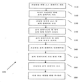
도 1a 내지 도 1b는 미세역가 플레이트 내의 2개의 웰 각각의 측단면도 및 평면도를 도시한 도면;
도 2a 내지 도 2c는 ELISA를 수행하는 공지된 방법 동안 미세역가 플레이트 내의 웰의 일련의 측단면도를 도시한 도면;
도 3은 일부 구체예에 따른 웰내 교정 특징부를 제조하는 방법을 도시한 도면;
도 4a 내지 도 4c는 일부 구체예에 따른 ELISA를 수행하는 방법 동안 미세역가 플레이트 내의 웰의 일련의 측단면도를 도시한 도면;
도 5는 일부 구체예에 따른 다수의 프린팅된 특징부를 갖는 미세역가 플레이트 내의 웰의 측단면도를 도시한 도면.BRIEF DESCRIPTION OF THE DRAWINGS Figures 1A-B show side cross-sectional and plan views of each of two wells in a microtiter plate;
Figures 2A-2C show a series of side cross-sectional views of a well in a microtiter plate during a known method of performing an ELISA;
Figure 3 illustrates a method of manufacturing a well-in-calibration feature in accordance with some embodiments;
Figures 4A-4C illustrate a series of side cross-sectional views of a well in a microtiter plate during a method of performing an ELISA according to some embodiments;
Figure 5 illustrates a side cross-sectional view of a well in a microtiter plate having a plurality of printed features in accordance with some embodiments.
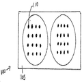
도 1a는 미세역가 플레이트(100) 내의 2개의 웰의 측단면도의 예시를 도시한다. 한 예시적 수행에서, 웰 기판은 폴리스타이렌 기부(base)(105)로 형성된다. 다른 잠재적 기판 물질은 나이트로셀룰로스, 유리, 및 다른 플라스틱 물질을 포함하지만, 이들로 제한되지는 않는다. 도 1b는 미세역가 플레이트(100) 내의 2개의 웰의 평면도의 예시를 도시한다. 생화학적 분석에서 사용하기 위한 미세역가 플레이트의 제조 동안, 많은 상이한 포획 항체 "특징부"(110)가 웰 내에 프린팅되고, 폴리스타이렌 기부(105)에 부착된다. 본원에서 사용되는 바와 같은 "특징부"는 다양한 형태, 예를 들어, 둥근 형태를 가질 수 있다. 검정 기판은, 예를 들어, 96-웰 미세역가 플레이트일 수 있다. 특징부는, 예를 들어, 약 300㎛ 내지 약 500㎛ 직경일 수 있다.1A shows an example of a side cross-sectional view of two wells in a
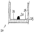
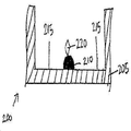
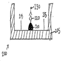
도 2a 내지 도 2c는 ELISA를 수행하는 공지된 방법 동안의 웰(205)의 일련의 측단면도(200)를 도시한다. 포획 항체 특징부(210)가 웰(205)의 바닥 상에 프린팅된 후, 차단 물질이 웰에 첨가되어 플레이트(200) 상에 남아있는 플레이트 결합 부위(215)가 차단된다. 이는 거짓 판독을 제공할 수 있는, ELISA 동안의 웰의 기부로의 샘플 항원의 비-선택적 결합을 방지한다. 둘째로, 항원-함유 샘플이 웰에 첨가된다. 도 2b는 포획 항체 특징부(210)에 대한 항원(220) 결합을 도시한다. 셋째로, 웰이 세척되어, 결합되지 않은 항원이 제거된다. 넷째로, 효소-결합된 검출 항체가 첨가된다. 도 2c는 항원(220)에 대한 효소-결합된 검출 항체(230) 결합을 도시한다. 이후, 웰이 세척되어, 결합되지 않은 항체-효소 컨쥬게이트가 제거된다. 다음으로, 효소를 검출가능한 신호, 예를 들어, 색, 형광, 또는 전기화학 신호로 전환시키는 물질이 적용된다. 마지막으로, 웰의 흡광도, 형광, 또는 전기화학 신호가 측정되고, 샘플 항원의 존재 및 양을 결정하기 위해 표준과 비교된다. 표준은 환자 샘플을 수용하는 웰과 별개의 웰 내에 공지된 농도의 항원을 갖는 교정 특징부를 프린팅함으로써 생성될 수 있다.2A-2C show a series of side
이러한 방법은 표준 결과와 상이한 웰로부터의 샘플 결과를 비교하는 것을 포함한다. 별개의 웰에서의 신호 변동성, 예를 들어, 형광 변동성, 및 웰간(well-to-well) 변동성은 시험 결과의 정확도 및 신뢰도를 감소시킬 수 있다.This method involves comparing the sample results from different wells with the standard results. Signal variability, e.g., fluorescence variability, and well-to-well variability in separate wells can reduce the accuracy and reliability of test results.
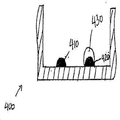
한 예시적 구체예에서, 도 4a는 2개의 포획 항체 특징부(410 및 420) 및 포획 항체 특징부(420)의 상부에 프린팅된 교정 특징부(430)를 갖는 한 플레이트의 측단면도를 도시한다. 교정 특징부(430)는 항원-함유 샘플에 결합하는 포획 항체 특징부(410)와 동일한 웰 내에 존재한다. 도 3은 일부 구체예에 따른 미세역가 플레이트 상에 웰내 교정 특징부를 프린팅하는 방법(300)을 도시한다. 상기 방법(300)은 항원-함유 샘플에 결합하는 포획 항체 특징부와 동일한 웰 내에 공지된 양의 항원을 갖는 교정 특징부를 프린팅함으로써 신호 변동성 및 웰간 변동성으로부터 발생할 수 있는 부정확성을 감소시키거나 배제시킨다. 상기 방법(300)은 검정 결과의 변동성을 감소시킬 뿐만 아니라, 처리량을 증가시킬 수 있는데, 이는 플레이트의 웰 모두가 환자 샘플을 분석하는데 이용될 수 있기 때문이다.In one exemplary embodiment, Figure 4a shows a side cross-sectional view of one plate having two capture antibody features 410 and 420 and a
적합한 샘플은 단백질체 샘플, 예를 들어, 세포 용해질, 세포 상층액, 혈장, 혈청, 또는 다른 생물학적 유체로부터의 단백질체 샘플을 포함한다. 본원에서 사용되는 바와 같은 "표적 플레이트"는 특정 세트의 분석을 위해 제조(예를 들어, 이후 사용을 위해 프린팅되고, 차단되고, 처리됨)되는 플레이트이다. "소스 플레이트(source plate)"는 표적 플레이트 상에 프린팅되는 물질의 공급을 갖는 플레이트이다. 예를 들어, 소스 플레이트의 웰은 표적 플레이트 상에 프린팅되는 다양한 유형의 항체로 충전될 수 있다. 상기 방법(300)에 따르면, 소스 플레이트는 프린팅 과정(단계 310)을 위해 제조된다. 이는 소스 플레이트의 웰을 표적 플레이트 상에 프린팅되는 요망되는 물질로 충전시키는 것을 포함할 수 있다. 다음으로, 표적 플레이트는 프린팅(단계 320)을 위해 제조된다. 이는 세척 및/또는 프린팅되는 물질이 플레이트 웰의 바닥 표면에 적절하게 부착되는 것을 가능케 하기 위해 다른 표면 처리를 수행하는 것을 포함할 수 있다.Suitable samples include protein sample from a protein sample, e. G., A cell lysate, cell supernatant, plasma, serum, or other biological fluid. As used herein, a "target plate" is a plate that is prepared (e.g., printed, blocked, and processed for later use) for a particular set of analyzes. A "source plate" is a plate having a supply of material to be printed on a target plate. For example, the wells of the source plate can be filled with various types of antibodies that are printed on a target plate. According to the
이후, 소스 및 표적 플레이트는 프린팅 장치(예를 들어, 매사추세츠주의 빌레리카시에 소재한 Aushon Biosystems, Inc.로부터 이용가능한 2470 Arrayer)에 조립(단계 330)된다. 포획 항체 특징부가 표적 플레이트의 웰 내에 프린팅(단계 340)된다. 다음으로, 공지된 농도의 항원을 갖는 교정 특징부가 포획 항체 특징부 상에 정밀하게 프린팅(단계 350)된다. 공지된 농도의 항원은 밀리리터 당 대략 펨토그램(10-15g) 내지 밀리리터 당 밀리그램(10-3g) 범위이다. 어레이어의 핀 크기와 관계없이 2470 Arrayer를 이용한 본 발명의 수행은 포획 항체 특징부 상으로의 교정 특징부의 정밀한 프린팅을 달성할 수 있어, 교정 특징부의 외부 에지와 포획 항체 특징부의 외부 에지 사이의 위치 정렬불량(positional misalignment)이 약 4㎛ 이하가 된다. 본 발명의 다른 수행은 특징부의 크기에 따라 약 4㎛를 초과하는 교정 특징부의 외부 에지와 포획 항체 특징부의 외부 에지 사이의 위치 정렬불량을 용인할 수 있다. 예를 들어, 프린팅 특징부가 약 120㎛ 내지 약 240㎛ 직경의 범위로 존재하는 경우, 약 10㎛의 교정 특징부의 외부 에지와 포획 항체 특징부의 외부 에지 사이의 위치 정렬불량이 용인될 수 있다.The source and target plates are then assembled (step 330) into a printing device (e.g., a 2470 Arrayer available from Aushon Biosystems, Inc., Villerica, Mass.). Capture antibody features are printed (step 340) into the wells of the target plate. Next, a calibration feature with a known concentration of antigen is precisely printed (step 350) on the capture antibody feature. A known concentration of antigen is in the range of about femtograms (10 -15 g) per milliliter to milligrams (10 -3 g) per milliliter. The performance of the present invention with the 2470 Arrayer regardless of the pin size of the interface layer can achieve precise printing of the calibration features onto the capture antibody features to ensure that the position between the outer edge of the calibration feature and the outer edge of the capture antibody feature The positional misalignment becomes about 4 탆 or less. Other implementations of the present invention may tolerate misalignment between the outer edge of the calibration feature and the outer edge of the capture antibody feature exceeding about 4 [mu] m, depending on the size of the feature. For example, misalignment between the outer edge of the calibration feature of about 10 microns and the outer edge of the capture antibody feature can be tolerated if the printing feature is in the range of about 120 microns to about 240 microns in diameter.
상기 기재된 바와 같이, 도 4a는 2개의 포획 항체 특징부(410 및 420) 및 포획 항체 특징부(420)의 상부에 프린팅된 교정 특징부(430)를 갖는 한 플레이트 웰의 측단면도를 도시한다. 교정 특징부(430)는 항원-함유 샘플에 결합하는 포획 항체 특징부(410)와 동일한 웰에 존재한다.4A shows a side cross-sectional view of a plate well having a
프린팅된 표적 플레이트는 일정 기간 동안 인큐베이션(단계 360)되고, 포획 항체와 반응하지 않는 차단 물질이 공지된 방법을 이용하여 표적 플레이트에 적용(단계 370)된다. 차단 물질은 플레이트의 남아있는 결합 표면에 흡착되고, 비-특이적 상호작용의 항원에 결합하며, 이에 따라 백그라운드 신호를 감소시킨다. 이후, 프린팅된 표적 플레이트가 건조(단계 380)된다. 한 예시적 수행에서, 차단 물질 용액은, 미국 가특허 출원 61/372,552호(출원일: 2010년 8월 11일, 발명의 명칭: "Method of and System for Applying Blocking Material to Assay Substrates", 이 문헌은 전체내용이 참조로서 본원에 포함됨)에 기재된 바와 같이 분무 과정을 통해 미세역가 플레이트 내의 복수의 웰의 바닥의 표면에 적용된다.The printed target plate is incubated (step 360) for a period of time and the blocking material that does not react with the capture antibody is applied to the target plate (step 370) using known methods. The blocking material adsorbs to the remaining binding surface of the plate and binds to an antigen of non-specific interaction, thereby reducing the background signal. Thereafter, the printed target plate is dried (step 380). In one exemplary implementation, the barrier material solution is disclosed in U. S. Patent Application 61 / 372,552, filed August 11, 2010, entitled " Method of and System for Applying Blocking Material to Assay Quot; Substrates & quot ;, which is incorporated herein by reference in its entirety) into the surface of the bottom of a plurality of wells in the microtiter plate through a spray process.
분무 과정 동안, 에어브러시(airbrush)(예를 들어, Paasche Talon 모델 TG0210)가 사용되어 차단 물질이 플레이트의 웰의 바닥 표면에 적용된다. 분무 단계 동안, 약 10 ㎖의 차단 물질 용액이 플레이트의 전체 표면 상에 분무된다. 차단 물질은 압축 공기 소스, 예를 들어, 약 138 kPa(20 psig)의 압력으로 깨끗하고 건조된 공기를 공급하는 표준 공기 압축기에 의해 추진된다. 에어브러시의 유속은 약 10 ㎖/분으로 설정된다. 차단 물질의 적용은 미세역가 웰로의 차단 물질의 첨가 동안 특징부의 기형 및/또는 토플링(toppling)을 감소시키거나 배제시킨다. 본원에 논의된 분무 과정에 따라 제조된 플레이트는 우수한 특징부 균일성을 갖는다.During the spraying process, an airbrush (e.g., Paasche Talon model TG0210) is used to apply the barrier material to the bottom surface of the wells of the plate. During the spraying step, about 10 ml of the barrier material solution is sprayed onto the entire surface of the plate. The barrier material is propelled by a standard air compressor that supplies clean and dry air to a source of compressed air, for example, at a pressure of about 138 kPa (20 psig). The flow rate of the airbrush is set at about 10 ml / min. The application of the blocking material reduces or eliminates the malformation and / or toppling of the features during the addition of the blocking material to the microtiter well. Plates produced according to the spray process discussed herein have excellent feature uniformity.
일부 구체예에서, 에어브러시의 노즐은 플레이트의 표면으로부터 약 15㎝ (6 인치)에 위치되며, 에어브러시는 노즐을 플레이트의 표면에 대해 직각으로 유지시키면서 전체 표면에 걸쳐 청소한다. 즉, 분무 패턴의 중심은 본질적으로 플레이트의 표면에 대해 통상적이다. 분무는 적어도 웰 내의 차단 물질의 수준이 프린팅된 특징부(530)를 덮을 때까지 지속된다. 차단 물질의 상기 수준이 달성된 후에, 분무 과정을 지속시킴으로써 추가 차단 물질이 첨가될 수 있거나, 임의로 추가 차단 물질이 본원에 기재된 바와 같이 마이크로피펫을 통해 첨가될 수 있다.In some embodiments, the nozzles of the airbrush are located at about 15 cm (6 inches) from the surface of the plate, and the airbrush cleans the entire surface while maintaining the nozzles at right angles to the surface of the plate. That is, the center of the spray pattern is inherently normal to the surface of the plate. Spraying continues until at least the level of blocking material in the well covers the printed features 530. After this level of blocking material is achieved, additional blocking material may be added by continuing the spraying process, or optionally additional blocking material may be added via a micropipette as described herein.
본원에 기재된 바와 같은 차단 물질의 적용은 수작업으로 적용될 수 있다. 일부 수행에서, 차단은 자동화된 기계장치에 의해 적용될 수 있다. 예를 들어, 프린팅, 인큐베이션 및 건조 후, 플레이트는 하나 이상의 분무 노즐이 마운팅되는 컨베이어 상에 배치될 수 있다. 컨베이어의 속도는 하나 이상의 노즐의 분무 패턴 내에서의 플레이트의 적절한 체류 시간을 보장하도록 조절된다. 예를 들어, 노즐 모두의 전체 유속이 약 10 ㎖/분인 경우, 컨베이어 속도는 플레이트의 표면의 적어도 일부가 1분 동안 분무 패턴 하에 있는 것을 제공하도록 조절될 수 있다. 또 다른 예시적 수행에서, 플레이트는 고정된 위치에서 유지될 수 있고, 자동화된 아암(arm)이 하나 이상의 분무 노즐이 플레이트의 표면 상을 향하도록 할 수 있다.The application of blocking substances as described herein can be applied by hand. In some implementations, blocking may be applied by an automated mechanism. For example, after printing, incubation and drying, the plate may be placed on a conveyor on which one or more spray nozzles are mounted. The speed of the conveyor is adjusted to ensure adequate residence time of the plate within the spray pattern of the one or more nozzles. For example, if the overall flow rate of both nozzles is about 10 ml / min, the conveyor speed can be adjusted to provide that at least a portion of the surface of the plate is under the spray pattern for one minute. In another exemplary implementation, the plate can be held in a fixed position and an automated arm can direct one or more spray nozzles onto the surface of the plate.
본원에 제공된 특정 작업 파라미터는 단지 예시이며, 다른 값이 본 발명의 범위에 속한다. 예를 들어, 차단 물질 유속은 5 내지 20 ㎖/분으로 다양할 수 있고, 에어브러시 유동 노즐과 플레이트의 표면 사이의 거리는 2 내지 41㎝(1 내지 16 인치)로 다양할 수 있으며, 공기압은 34 내지 207 kPa(5 내지 30 psig)로 다양할 수 있다. 이러한 범위는 단지 예시이며, 이로 제한하고자 하는 것이 아님이 이해된다.The specific working parameters provided herein are exemplary only, and other values fall within the scope of the present invention. For example, the flow rate of the barrier material may vary from 5 to 20 ml / min, and the distance between the airbrush flow nozzle and the surface of the plate may vary from 2 to 41 cm (1 to 16 inches) To 5 kPa (5 to 30 psig). It is understood that this scope is merely illustrative and not intended to be limiting.
이후, 표적 플레이트는 공지된 방법(단계 390)을 이용하여 사용 또는 저장을 위해 처리된다. 예를 들어, 표적 플레이트는 밤새 약 4℃에서 인큐베이션될 수 있다. 대안적으로, 과도한 차단 물질(예를 들어, 웰의 바닥에 결합되지 않은 차단 물질)이 표적 플레이트로부터 제거될 수 있고, 이후 플레이트는 건조될 수 있으며, 이후 플레이트는 저장을 위해 수분-저항성 패키지에 배치될 수 있다. 웰내 교정 특징부를 프린팅하는 개시된 방법은 항원-함유 샘플에 결합하는 포획 항체 특징부와 별개의 웰에 프린팅되는 교정 특징부로부터 발생할 수 있는 부정확성을 감소시키거나 배제시킨다. 개시된 방법은 또한 처리량을 증가시키는데, 이는 플레이트의 모든 웰이 환자 샘플을 분석하는데 사용될 수 있기 때문이다.The target plate is then processed for use or storage using a known method (step 390). For example, the target plate can be incubated at about 4 ° C overnight. Alternatively, excess blocking material (e.g., blocking material that is not bound to the bottom of the well) may be removed from the target plate, after which the plate may be dried and then the plate is placed in a moisture- . The disclosed method of printing the in-well correction features reduces or eliminates inaccuracies that may arise from calibration features that are printed on separate wells from the capture antibody features that bind to the antigen-containing sample. The disclosed method also increases the throughput because all the wells of the plate can be used to analyze the patient sample.
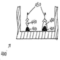
이후, 웰내 교정 특징부를 갖는 플레이트가 화학적 및/또는 생물학적 분석, 예를 들어, ELISA를 이용한 분석을 수행하는데 이용될 수 있다. 도 4b는 항원-함유 샘플이 첨가된 후의 웰의 측단면도를 도시하며, 환자 항원(440)이 포획 항체(410)에 결합한다. 다음으로, 효소-결합된 검출 항체가 웰에 첨가된다. 도 4c는 항원(440) 및 교정 특징부(430)에 결합하는 효소-결합된 검출 항체(450)를 도시한다. 물질, 예를 들어, 화학발광 기질 용액이 적용되어 효소가 검출가능한 신호로 전환된다. 최종적으로, 신호가 측정되고, 샘플 항원의 존재 및 양이 당 분야에 공지된 방법을 이용하여 결정된다.Plates with in-well correcting features can then be used to perform chemical and / or biological assays, e.g., ELISA assays. 4B shows a side cross-sectional view of the well after the antigen-containing sample has been added, wherein the
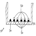
또 다른 예시적 구체예에서, 2개 이상의 포획 항체 특징부가 각각의 웰 상에 프린팅될 수 있고, 다양한 항원 농도의 하나 이상의 교정 특징부가 각각의 웰 상에 프린팅될 수 있다. 도 5는 웰(505)의 바닥에 프린팅된 포획 항체 특징부(510 및 520)를 갖는 한 플레이트 웰의 측단면도를 도시한다. 다양한 농도의 항원을 갖는 5개의 교정 특징부(530)가 포획 항체 특징부(520)의 상부에 정밀하게 프린팅된다. 다양한 농도의 항원을 갖는 교정 특징부의 시리즈가 표준 곡선을 생성시키는데 사용될 수 있다. 공지된 다양한 농도의 교정 특징부와 관련하여, 이러한 특징부는 공지된 농도와 관련된 다양한 강도의 검출가능한 신호를 생성시킨다. 표준 곡선은 항원-함유 시험 샘플에 대한 포획 항체 특징부 결합의 신호와 비교되어, 샘플 항원의 존재 및 양이 결정될 수 있다. 본 발명에 개시된 방법은 항원-함유 샘플에 결합하는 포획 항체 특징부와 별개의 웰에 프린팅된 교정 특징부의 시리즈로부터 발생할 수 있는 부정확성을 감소시키거나 배제시킨다. 이는 또한 처리량 및 검정 및 기타 분석의 효율을 증가시킨다.In another exemplary embodiment, two or more capture antibody feature portions can be printed on each well, and one or more calibration features of various antigen concentrations can be printed on each well. 5 shows a side cross-sectional view of a plate well having capture antibody features 510 and 520 printed on the bottom of
상기 제공된 특정 작업 파라미터는 단지 예시이며, 다른 값이 본 발명의 범위에 속한다.The specific task parameters provided above are exemplary only, and other values fall within the scope of the present invention.
상기 장치와 함께 관련 장비 또는 시약의 임의의 조합물, 예를 들어, 리포터 시약 또는 검정의 결과를 판독하기 위한 소프트웨어를 포함하는 키트가 제조될 수 있다.Kits may be prepared that include any combination of related equipment or reagents with the apparatus, for example, software for reading the results of a reporter reagent or assay.
환자, 예를 들어, 자가면역 질병을 갖는 환자의 항원 및 단백질, 예를 들어, 바이러스 질병에 대한 항체, 박테리아 질병에 대한 항체, 알레르기 반응에 대한 항체, 또는 암에 대한 항체의 존재를 검출하기 위해 상기 기재된 구체예가 이용될 수 있다.To detect the presence of an antigen and a protein of a patient having an autoimmune disease, for example, an antibody against a viral disease, an antibody against a bacterial disease, an antibody against an allergic reaction, or an antibody against cancer The embodiments described above can be used.
본원에서 이용되는 용어 및 표현은 설명의 용어이며, 제한되는 용어가 아니다. 상기 용어 및 표현의 사용은 제시되거나 기재된 특징부의 동등물 또는 이의 일부를 배제하고자 하는 것이 아니며, 청구되는 바와 같은 본 발명의 범위 내에서 다양한 변형이 가능함이 인지된다.The terms and expressions used herein are words of description and not of limitation. It is to be appreciated that the use of the terms and expressions is not intended to exclude the equivalents of the features or parts described or portions thereof, and that various modifications are possible within the scope of the invention as claimed.
Claims (15)
시험 기판;
시험 기판의 웰 내의 복수의 포획 화합물 특징부(capture compound feature);
포획 화합물에 결합할 수 있는 공지된 농도의 화합물을 지니는, 시험 기판의 웰 내의 포획 화합물 특징부 중 하나 상의 교정 특징부; 및
상기 시험 기판의 동일 웰 내의 적어도 하나의 추가 포획 화합물 특징부를 포함하되,
상기 적어도 하나의 추가 포획 화합물 특징부는 적어도 하나의 추가 포획 화합물 특징부 상에 프린팅된 교정 특징부를 갖지 않는 적어도 하나의 추가 포획 화합물 특징부를 포함하는 것인 장치.As an apparatus,
Test board;
A plurality of capture compound features in the wells of the test substrate;
A calibration feature on one of the capture compound features in the well of the test substrate, having a known concentration of the compound capable of binding to the capture compound; And
At least one additional capture compound feature in the same well of the test substrate,
Wherein the at least one additional capture compound feature comprises at least one additional capture compound feature that does not have a calibration feature printed on at least one additional capture compound feature.
시험 기판의 웰 내에 복수의 포획 화합물 특징부를 프린팅하는 단계; 및
상기 시험 기판의 웰 내의 상기 포획 화합물 특징부 중 하나 상에 교정 특징부를 프린팅하는 단계를 포함하되,
상기 교정 특징부는 상기 포획 화합물에 결합할 수 있는 공지된 농도의 화합물을 지니고,
상기 적어도 하나의 포획 화합물 특징부는 적어도 하나의 포획 화합물 특징부 상에 프린팅된 교정 특징부를 갖지 않는 것인 방법.As a method,
Printing a plurality of trapping compound features in the wells of the test substrate; And
And printing a calibration feature on one of the capture compound features in a well of the test substrate,
The calibration feature has a known concentration of compound capable of binding to the capture compound,
Wherein said at least one capture compound feature does not have a calibration feature printed on at least one capture compound feature.
프린팅된 상기 시험 기판을 인큐베이션시키는 단계;
상기 시험 기판에 차단 물질을 적용시키는 단계;
상기 프린팅된 시험 기판을 건조시키는 단계; 및
사용 또는 저장을 위해 상기 프린팅된 시험 기판을 처리하는 단계를 추가로 포함하는 방법.9. The method according to claim 7 or 8,
Incubating the printed test substrate;
Applying a blocking material to the test substrate;
Drying the printed test substrate; And
Further comprising the step of treating the printed test substrate for use or storage.
상기 교정 곡선을 항원-함유 시험 샘플에 결합하는 포획 항체 특징부의 신호와 비교하는 단계; 및
시험 샘플 내의 항원의 존재 및 양을 결정하는 단계를 추가로 포함하는 방법.13. The method of claim 12, further comprising: using a result from at least two different concentrations of the compound capable of binding to the entrapped compound to produce a calibration curve;
Comparing the calibration curve with a signal of a capture antibody characteristic binding to an antigen-containing test sample; And
Further comprising the step of determining the presence and amount of the antigen in the test sample.
Applications Claiming Priority (3)
| Application Number | Priority Date | Filing Date | Title |
|---|---|---|---|
| US41466310P | 2010-11-17 | 2010-11-17 | |
| US61/414,663 | 2010-11-17 | ||
| PCT/US2011/061184 WO2012068372A1 (en) | 2010-11-17 | 2011-11-17 | Method of and system for printing in-well calibration features |
Publications (1)
| Publication Number | Publication Date |
|---|---|
| KR20140063499A true KR20140063499A (en) | 2014-05-27 |
Family
ID=46084414
Family Applications (1)
| Application Number | Title | Priority Date | Filing Date |
|---|---|---|---|
| KR1020137015223A KR20140063499A (en) | 2010-11-17 | 2011-11-17 | Method of and system for printing in-well calibration features |
Country Status (6)
| Country | Link |
|---|---|
| US (2) | US20130266969A1 (en) |
| EP (1) | EP2640876B1 (en) |
| JP (1) | JP6203638B2 (en) |
| KR (1) | KR20140063499A (en) |
| CA (1) | CA2818483C (en) |
| WO (1) | WO2012068372A1 (en) |
Families Citing this family (6)
| Publication number | Priority date | Publication date | Assignee | Title |
|---|---|---|---|---|
| GB0913258D0 (en) | 2009-07-29 | 2009-09-02 | Dynex Technologies Inc | Reagent dispenser |
| US9523701B2 (en) | 2009-07-29 | 2016-12-20 | Dynex Technologies, Inc. | Sample plate systems and methods |
| EP2780112B1 (en) * | 2011-11-14 | 2020-01-08 | Aushon Biosystems Inc. | Systems and methods to enhance consistency of assay performance |
| US10562032B2 (en) | 2017-05-26 | 2020-02-18 | Aushon Biosystems, Inc. | Systems and methods for automatic plate washing |
| US11686730B2 (en) | 2020-04-30 | 2023-06-27 | Quanterix Corporation | Quantitative antibody test |
| GB202010627D0 (en) | 2020-07-10 | 2020-08-26 | Qbd (Qs-Ip) Ltd | Blocking method |
Family Cites Families (18)
| Publication number | Priority date | Publication date | Assignee | Title |
|---|---|---|---|---|
| US5395754A (en) * | 1992-07-31 | 1995-03-07 | Hybritech Incorporated | Membrane-based immunoassay method |
| AU2002305337A1 (en) * | 2001-05-03 | 2002-11-18 | Genometrix Genomics, Inc. | Method and apparatus to determine the performance of protein arrays |
| US20030198967A1 (en) * | 2002-04-23 | 2003-10-23 | Matson Robert S. | Multi-functional microarrays and methods |
| US20040049351A1 (en) * | 2002-08-28 | 2004-03-11 | Matson Robert S. | Immunosorbent assay in microarray format |
| US20040121334A1 (en) * | 2002-12-19 | 2004-06-24 | Kimberly-Clark Worldwide, Inc. | Self-calibrated flow-through assay devices |
| US20040229226A1 (en) * | 2003-05-16 | 2004-11-18 | Reddy M. Parameswara | Reducing microarray variation with internal reference spots |
| GB0311902D0 (en) * | 2003-05-22 | 2003-06-25 | Cambridge Life Sciences | Assay method and apparatus |
| FR2864550B1 (en) * | 2003-12-29 | 2006-02-24 | Commissariat Energie Atomique | CHIP OF ANALYSIS WITH STANDARD RANGE, KITS AND METHODS OF ANALYSIS. |
| US20050266398A1 (en) * | 2004-06-01 | 2005-12-01 | Peter Lea | Method and device for rapid detection and quantitation of macro and micro matrices |
| CA2475456A1 (en) * | 2004-07-20 | 2006-01-20 | Biophys, Inc. | Method and device to optimize analyte and antibody substrate binding by least energy adsorption |
| US20060292586A1 (en) * | 2004-12-17 | 2006-12-28 | Schroth Gary P | ID-tag complexes, arrays, and methods of use thereof |
| US20060141527A1 (en) * | 2004-12-29 | 2006-06-29 | Caracci Stephen J | Method for creating a reference region and a sample region on a biosensor and the resulting biosensor |
| CA2627360C (en) * | 2005-10-29 | 2014-06-10 | Bayer Technology Services Gmbh | Process for determining one or more analytes in samples of biological origin having complex composition, and use thereof |
| FR2894596B1 (en) * | 2005-12-13 | 2012-08-10 | Centre Nat Rech Scient | PROCESS FOR AUTOCALIBRATION OF BIOPUCES |
| US20070259366A1 (en) * | 2006-05-03 | 2007-11-08 | Greg Lawrence | Direct printing of patterned hydrophobic wells |
| WO2008007159A1 (en) * | 2006-07-14 | 2008-01-17 | Eötvös Lorand University | Measurement of complement activation products on antigen arrays |
| WO2008067091A2 (en) * | 2006-11-28 | 2008-06-05 | Pictor Limited | Assay membrane and method of use thereof |
| CA2647953A1 (en) * | 2008-12-29 | 2010-06-29 | Sqi Diagnostics Systems Inc. | Multiplex analyte detection |
-
2011
- 2011-11-17 JP JP2013540013A patent/JP6203638B2/en not_active Expired - Fee Related
- 2011-11-17 EP EP11840749.3A patent/EP2640876B1/en active Active
- 2011-11-17 KR KR1020137015223A patent/KR20140063499A/en not_active Application Discontinuation
- 2011-11-17 CA CA2818483A patent/CA2818483C/en active Active
- 2011-11-17 WO PCT/US2011/061184 patent/WO2012068372A1/en active Application Filing
-
2012
- 2012-09-28 US US13/630,917 patent/US20130266969A1/en not_active Abandoned
-
2017
- 2017-12-22 US US15/852,939 patent/US20180120310A1/en not_active Abandoned
Also Published As
| Publication number | Publication date |
|---|---|
| JP6203638B2 (en) | 2017-09-27 |
| EP2640876A1 (en) | 2013-09-25 |
| WO2012068372A1 (en) | 2012-05-24 |
| CA2818483C (en) | 2020-12-15 |
| EP2640876B1 (en) | 2017-03-01 |
| US20180120310A1 (en) | 2018-05-03 |
| CA2818483A1 (en) | 2012-05-24 |
| JP2013543981A (en) | 2013-12-09 |
| US20130266969A1 (en) | 2013-10-10 |
| EP2640876A4 (en) | 2014-04-16 |
Similar Documents
| Publication | Publication Date | Title |
|---|---|---|
| US20180120310A1 (en) | Method of and System for Printing In-Well Calibration Features | |
| JP4906725B2 (en) | Sample presentation device | |
| US20220048025A1 (en) | Systems and methods to enhance consistency of assay performance | |
| JP2013543981A5 (en) | ||
| US10191037B2 (en) | Methods of and systems for improved detection sensitivity of assays | |
| JP4253695B2 (en) | Substance determination method and substance determination device | |
| Zuo et al. | Determination of β-adrenergic agonists by hapten microarray | |
| EP1512012B1 (en) | Biomolecular kinetics method using a flow-through microarray | |
| Bang-Ce et al. | Simultaneous detection of sulfamethazine, streptomycin, and tylosin in milk by microplate-array based SMM–FIA | |
| JP6093301B2 (en) | Method and system for applying a blocking material to an assay substrate | |
| WO2018154814A1 (en) | Biomaterial immobilizing method and uses thereof | |
| JP2007285835A (en) | Plate for bioplate, manufacturing method therefor and the bioplate | |
| US20200400664A1 (en) | NiO CHIP AND THE PREPARING METHOD AND USE THEREOF | |
| RU2021126211A (en) | NON-INVASIVE PAPER-BASED DEVICE FOR PREGNANCY DETECTION IN CATTLE AND Buffalo |
Legal Events
| Date | Code | Title | Description |
|---|---|---|---|
| E902 | Notification of reason for refusal | ||
| E902 | Notification of reason for refusal | ||
| E601 | Decision to refuse application |