JP6203638B2 - Method and system for printing an in-well calibration mechanism - Google Patents
Method and system for printing an in-well calibration mechanism Download PDFInfo
- Publication number
- JP6203638B2 JP6203638B2 JP2013540013A JP2013540013A JP6203638B2 JP 6203638 B2 JP6203638 B2 JP 6203638B2 JP 2013540013 A JP2013540013 A JP 2013540013A JP 2013540013 A JP2013540013 A JP 2013540013A JP 6203638 B2 JP6203638 B2 JP 6203638B2
- Authority
- JP
- Japan
- Prior art keywords
- antigen
- capture antibody
- well
- calibration
- sample
- Prior art date
- Legal status (The legal status is an assumption and is not a legal conclusion. Google has not performed a legal analysis and makes no representation as to the accuracy of the status listed.)
- Expired - Fee Related
Links
Images


Classifications
-
- G—PHYSICS
- G01—MEASURING; TESTING
- G01N—INVESTIGATING OR ANALYSING MATERIALS BY DETERMINING THEIR CHEMICAL OR PHYSICAL PROPERTIES
- G01N33/00—Investigating or analysing materials by specific methods not covered by groups G01N1/00 - G01N31/00
- G01N33/48—Biological material, e.g. blood, urine; Haemocytometers
- G01N33/50—Chemical analysis of biological material, e.g. blood, urine; Testing involving biospecific ligand binding methods; Immunological testing
- G01N33/53—Immunoassay; Biospecific binding assay; Materials therefor
- G01N33/543—Immunoassay; Biospecific binding assay; Materials therefor with an insoluble carrier for immobilising immunochemicals
- G01N33/54393—Improving reaction conditions or stability, e.g. by coating or irradiation of surface, by reduction of non-specific binding, by promotion of specific binding
-
- C—CHEMISTRY; METALLURGY
- C40—COMBINATORIAL TECHNOLOGY
- C40B—COMBINATORIAL CHEMISTRY; LIBRARIES, e.g. CHEMICAL LIBRARIES
- C40B30/00—Methods of screening libraries
- C40B30/04—Methods of screening libraries by measuring the ability to specifically bind a target molecule, e.g. antibody-antigen binding, receptor-ligand binding
-
- B—PERFORMING OPERATIONS; TRANSPORTING
- B01—PHYSICAL OR CHEMICAL PROCESSES OR APPARATUS IN GENERAL
- B01L—CHEMICAL OR PHYSICAL LABORATORY APPARATUS FOR GENERAL USE
- B01L3/00—Containers or dishes for laboratory use, e.g. laboratory glassware; Droppers
- B01L3/50—Containers for the purpose of retaining a material to be analysed, e.g. test tubes
- B01L3/508—Containers for the purpose of retaining a material to be analysed, e.g. test tubes rigid containers not provided for above
- B01L3/5085—Containers for the purpose of retaining a material to be analysed, e.g. test tubes rigid containers not provided for above for multiple samples, e.g. microtitration plates
-
- G—PHYSICS
- G01—MEASURING; TESTING
- G01N—INVESTIGATING OR ANALYSING MATERIALS BY DETERMINING THEIR CHEMICAL OR PHYSICAL PROPERTIES
- G01N33/00—Investigating or analysing materials by specific methods not covered by groups G01N1/00 - G01N31/00
- G01N33/48—Biological material, e.g. blood, urine; Haemocytometers
- G01N33/50—Chemical analysis of biological material, e.g. blood, urine; Testing involving biospecific ligand binding methods; Immunological testing
- G01N33/53—Immunoassay; Biospecific binding assay; Materials therefor
- G01N33/543—Immunoassay; Biospecific binding assay; Materials therefor with an insoluble carrier for immobilising immunochemicals
- G01N33/54366—Apparatus specially adapted for solid-phase testing
-
- B—PERFORMING OPERATIONS; TRANSPORTING
- B01—PHYSICAL OR CHEMICAL PROCESSES OR APPARATUS IN GENERAL
- B01J—CHEMICAL OR PHYSICAL PROCESSES, e.g. CATALYSIS OR COLLOID CHEMISTRY; THEIR RELEVANT APPARATUS
- B01J2219/00—Chemical, physical or physico-chemical processes in general; Their relevant apparatus
- B01J2219/00274—Sequential or parallel reactions; Apparatus and devices for combinatorial chemistry or for making arrays; Chemical library technology
- B01J2219/00277—Apparatus
- B01J2219/00279—Features relating to reactor vessels
- B01J2219/00306—Reactor vessels in a multiple arrangement
- B01J2219/00313—Reactor vessels in a multiple arrangement the reactor vessels being formed by arrays of wells in blocks
- B01J2219/00315—Microtiter plates
-
- B—PERFORMING OPERATIONS; TRANSPORTING
- B01—PHYSICAL OR CHEMICAL PROCESSES OR APPARATUS IN GENERAL
- B01J—CHEMICAL OR PHYSICAL PROCESSES, e.g. CATALYSIS OR COLLOID CHEMISTRY; THEIR RELEVANT APPARATUS
- B01J2219/00—Chemical, physical or physico-chemical processes in general; Their relevant apparatus
- B01J2219/00274—Sequential or parallel reactions; Apparatus and devices for combinatorial chemistry or for making arrays; Chemical library technology
- B01J2219/00277—Apparatus
- B01J2219/00351—Means for dispensing and evacuation of reagents
- B01J2219/00385—Printing
-
- B—PERFORMING OPERATIONS; TRANSPORTING
- B01—PHYSICAL OR CHEMICAL PROCESSES OR APPARATUS IN GENERAL
- B01J—CHEMICAL OR PHYSICAL PROCESSES, e.g. CATALYSIS OR COLLOID CHEMISTRY; THEIR RELEVANT APPARATUS
- B01J2219/00—Chemical, physical or physico-chemical processes in general; Their relevant apparatus
- B01J2219/00274—Sequential or parallel reactions; Apparatus and devices for combinatorial chemistry or for making arrays; Chemical library technology
- B01J2219/00277—Apparatus
- B01J2219/0054—Means for coding or tagging the apparatus or the reagents
- B01J2219/00572—Chemical means
- B01J2219/00576—Chemical means fluorophore
-
- B—PERFORMING OPERATIONS; TRANSPORTING
- B01—PHYSICAL OR CHEMICAL PROCESSES OR APPARATUS IN GENERAL
- B01J—CHEMICAL OR PHYSICAL PROCESSES, e.g. CATALYSIS OR COLLOID CHEMISTRY; THEIR RELEVANT APPARATUS
- B01J2219/00—Chemical, physical or physico-chemical processes in general; Their relevant apparatus
- B01J2219/00274—Sequential or parallel reactions; Apparatus and devices for combinatorial chemistry or for making arrays; Chemical library technology
- B01J2219/0068—Means for controlling the apparatus of the process
- B01J2219/00693—Means for quality control
-
- B—PERFORMING OPERATIONS; TRANSPORTING
- B01—PHYSICAL OR CHEMICAL PROCESSES OR APPARATUS IN GENERAL
- B01J—CHEMICAL OR PHYSICAL PROCESSES, e.g. CATALYSIS OR COLLOID CHEMISTRY; THEIR RELEVANT APPARATUS
- B01J2219/00—Chemical, physical or physico-chemical processes in general; Their relevant apparatus
- B01J2219/00274—Sequential or parallel reactions; Apparatus and devices for combinatorial chemistry or for making arrays; Chemical library technology
- B01J2219/00718—Type of compounds synthesised
- B01J2219/0072—Organic compounds
- B01J2219/00725—Peptides
-
- B—PERFORMING OPERATIONS; TRANSPORTING
- B01—PHYSICAL OR CHEMICAL PROCESSES OR APPARATUS IN GENERAL
- B01J—CHEMICAL OR PHYSICAL PROCESSES, e.g. CATALYSIS OR COLLOID CHEMISTRY; THEIR RELEVANT APPARATUS
- B01J2219/00—Chemical, physical or physico-chemical processes in general; Their relevant apparatus
- B01J2219/00274—Sequential or parallel reactions; Apparatus and devices for combinatorial chemistry or for making arrays; Chemical library technology
- B01J2219/00718—Type of compounds synthesised
- B01J2219/0072—Organic compounds
- B01J2219/0074—Biological products
-
- B—PERFORMING OPERATIONS; TRANSPORTING
- B01—PHYSICAL OR CHEMICAL PROCESSES OR APPARATUS IN GENERAL
- B01L—CHEMICAL OR PHYSICAL LABORATORY APPARATUS FOR GENERAL USE
- B01L2200/00—Solutions for specific problems relating to chemical or physical laboratory apparatus
- B01L2200/14—Process control and prevention of errors
- B01L2200/148—Specific details about calibrations
-
- B—PERFORMING OPERATIONS; TRANSPORTING
- B01—PHYSICAL OR CHEMICAL PROCESSES OR APPARATUS IN GENERAL
- B01L—CHEMICAL OR PHYSICAL LABORATORY APPARATUS FOR GENERAL USE
- B01L2300/00—Additional constructional details
- B01L2300/06—Auxiliary integrated devices, integrated components
- B01L2300/0627—Sensor or part of a sensor is integrated
- B01L2300/0636—Integrated biosensor, microarrays
-
- B—PERFORMING OPERATIONS; TRANSPORTING
- B01—PHYSICAL OR CHEMICAL PROCESSES OR APPARATUS IN GENERAL
- B01L—CHEMICAL OR PHYSICAL LABORATORY APPARATUS FOR GENERAL USE
- B01L2300/00—Additional constructional details
- B01L2300/08—Geometry, shape and general structure
- B01L2300/0809—Geometry, shape and general structure rectangular shaped
- B01L2300/0829—Multi-well plates; Microtitration plates
Description
関連出願の相互参照
本出願は、その全体が参照により本明細書に組み込まれる、2010年11月17日に出願され、「METHOD OF AND SYSTEM FOR PRINTING IN−WELL CALIBRATION FEATURES」と題された米国特許仮出願第61/414663号の35合衆国法典(U.S.C.)§119(e)の下、利益を主張するものである。
CROSS REFERENCE TO RELATED APPLICATIONS This application is filed on November 17, 2010, which is hereby incorporated by reference in its entirety, and is entitled “METHOD OF AND SYSTEM FOR PRINTING IN-WELL CALIBRATION FEATURES”. Claims benefit under 35 U.S. Code (U.S.C.) §119 (e) of provisional application 61/414663.
本発明は、アッセイ基板の調製に関し、より具体的には、ウェル内検量機構をアッセイ基板上に印刷するための方法及びシステムに関する。 The present invention relates to the preparation of assay substrates and, more particularly, to methods and systems for printing in-well calibration mechanisms on assay substrates.
関連技術の説明
アッセイ基板は、その上で様々な化学的及び/又は生物学的分析が実施され得る表面である。アッセイ基板の例としては、マイクロアレイプレート、スライドガラス、及びマイクロタイタープレートが挙げられる。マイクロタイタープレートは、その表面に形成された複数の「ウェル」を有する平板面である。各々のウェルは、その中に様々な材料が配置されて、生物学的分析を実施することが可能な小型試験管として使用され得る。マイクロタイタープレートの1つの例示的使用としては、酵素結合免疫吸着測定法(ELISA)が挙げられ、これは、現代の医療的診断試験技術である。
Description of Related Art An assay substrate is a surface on which various chemical and / or biological analyzes can be performed. Examples of assay substrates include microarray plates, glass slides, and microtiter plates. The microtiter plate is a flat plate surface having a plurality of “wells” formed on the surface thereof. Each well can be used as a small test tube in which various materials can be placed to perform biological analysis. One exemplary use of microtiter plates includes enzyme-linked immunosorbent assay (ELISA), which is a modern medical diagnostic test technique.
一般的に、ELISAにおいては、捕捉抗体がマイクロタイタープレート内のウェルの底部に印刷される。捕捉抗体は、それに対するアッセイが実施される特定の抗原に関して特異性を有する。分析される試料が、この捕捉抗体を含有するウェルに添加され、捕捉抗体が、試料中に含有される抗原を「捕捉」又は固定化する。次いで検出抗体がウェルに添加され、これがまた抗原に結合し及び/又は抗原と複合体を形成する。次いで更なる材料がウェルに添加され、これが検出抗体によって検出可能な信号を発生させる。例えば、特定の波長の光がウェル上に照射される場合、抗原/抗体複合体は蛍光を発するだろう。試料中の抗原の量は、蛍光の大きさに基づいて推測され得る。別の例において、検出抗体に所定の波長(例えば、400〜500nm)内で光を放射させる化合物がウェルに添加され得る。この光は、電荷結合素子(CCD)カメラによって読み取られ、放射された光の光学的輝度を測定することができる。 In general, in an ELISA, the capture antibody is printed at the bottom of a well in a microtiter plate. The capture antibody has specificity for the particular antigen for which the assay is performed. The sample to be analyzed is added to the well containing the capture antibody, which captures or immobilizes the antigen contained in the sample. A detection antibody is then added to the well, which also binds to and / or forms a complex with the antigen. Additional material is then added to the well, which generates a signal detectable by the detection antibody. For example, when light of a specific wavelength is irradiated onto the well, the antigen / antibody complex will fluoresce. The amount of antigen in the sample can be inferred based on the magnitude of fluorescence. In another example, a compound that causes the detection antibody to emit light within a predetermined wavelength (eg, 400-500 nm) can be added to the well. This light can be read by a charge coupled device (CCD) camera and the optical brightness of the emitted light can be measured.
ELISAの過程中に、ウェルの吸光度、蛍光、又は電気化学的信号が測定され得、試料抗原の存在及び量をより正確に決定するために、標準と比較され得る。例えば、抗原の既知の濃度を有する検量機構が、抗原含有の患者試料を受容するウェルとは離れたウェルに配置されることができる。しかしながら、異なるウェルにおける蛍光の可変性などの信号の可変性が、個々のウェルからの結果を比較する上での精度を低減させる可能性がある。 During the course of the ELISA, the absorbance, fluorescence, or electrochemical signal of the wells can be measured and compared to a standard to more accurately determine the presence and amount of sample antigen. For example, a calibration mechanism with a known concentration of antigen can be placed in a well separate from the well that receives the antigen-containing patient sample. However, signal variability, such as fluorescence variability in different wells, can reduce accuracy in comparing results from individual wells.
したがって、医療的診断試験技術及び他の生化学的分析における精度及び信頼性を提供しかつ改善するための方法及びシステムへの要求が存在する。 Accordingly, there is a need for methods and systems for providing and improving accuracy and reliability in medical diagnostic testing techniques and other biochemical analyses.
図1Aは、マイクロタイタープレート100内の2つのウェルの断面図の図説を示す。1つの例示的実装において、ウェル基板は、ポリスチレン基部105から形成される。他の可能性がある基板材料としては、ニトロセルロース、ガラス、及び他の可塑性材料が挙げられるが、これらに限定されない。図1Bは、マイクロタイタープレート100内の2つのウェルの上面図の図説である。生化学的分析における使用のためのマイクロタイタープレートの調製中に、多くの異なる捕捉抗体「機構」110が、ウェル内に印刷され、ポリスチレン基部105に付着する。本明細書で使用する場合、「機構」は、異なる形状、例えば丸形形状などを有することができる。このアッセイ基板は、例えば、96−ウェルのマイクロタイタープレートであることができる。この機構は、例えば、直径で約300μm〜約500μmであり得る。
FIG. 1A shows an illustration of a cross-sectional view of two wells in a
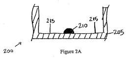
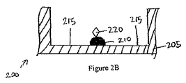
図2A〜Cは、ELISAを実行する既知の方法の過程中のウェル205の一連の断面図200を示す。捕捉抗体機構210がウェル205の底部に印刷された後に、プレート200上に残留するプレート結合部位215を遮断するために、ブロッキング材料が添加される。これが、誤った読み取りをもたらす可能性がある、ELISA中での試料抗原のウェルの基部への非選択的結合を抑制する。第2に、抗原含有試料がウェルに添加される。図2Bは、捕捉抗体機構210に結合する抗原220を示す。第3に、このウェルが、未結合抗体が除去されるように、洗浄される。第4に、酵素結合検出抗体が添加される。図2Cは、抗原220に結合している酵素結合検出抗体230を示す。次いで、このウェルが、未結合抗体−酵素複合体が除去されるよう洗浄される。次に、酵素を、色、蛍光、又は電気化学的信号などの検出可能な信号に変換する物質が加えられる。最後に、ウェルの吸光度、蛍光、又は電気化学的信号が測定され、標準と比較され、試料抗原の存在及び量を決定する。標準は、患者試料を受容するウェルから離れているウェル内に抗原の既知濃度を有する検量機構を印刷することによって生成され得る。
2A-C show a series of
このようなアプローチは、標準結果と、異なるウェルからの試料結果を比較することを伴う。蛍光可変性などの信号可変性並びに別個のウェルにおけるウェル間の可変性は、試験結果の精度及び信頼性を低減させる可能性がある。 Such an approach involves comparing standard results with sample results from different wells. Signal variability, such as fluorescence variability, and variability between wells in separate wells can reduce the accuracy and reliability of test results.
1つの例示的実施形態では、図4Aは2つの捕捉抗体機構410及び420並びに捕捉抗体機構420の上部に印刷された検量機構430を備える1つのプレートウェルの断面図を示す。この検量機構430は、抗原含有試料に結合する捕捉抗体機構410と同一のウェル内にある。図3は、いくつかの実施形態によるマイクロタイタープレート上にウェル内検量機構を印刷する方法300を示す。方法300は、抗原の既知量を備える検量機構を抗原含有試料に結合する捕捉抗体機構と同一のウェル内に印刷することによって、信号可変性及びウェル間の可変性から生じ得る不正確さを低減又は排除する。方法300はアッセイ結果の変動を低減するだけではなく、プレートの全てのウェルが患者試料を分析するよう使用され得るので、処理能力も増加させる。
In one exemplary embodiment, FIG. 4A shows a cross-sectional view of one plate well with two
好適な試料としては、例えば、細胞溶解液、細胞上清液、血漿、血清、又は他の生物学的体液などのプロテオミクス試料が挙げられる。本明細書で使用する場合、「ターゲットプレート」とは、分析の特定のセットのために調製される(例えば、印刷され、遮断され、及び後の使用にために処理される)プレートである。「ソースプレート」とは、ターゲットプレート上に印刷される材料の供給源を有するプレートである。例えば、ソースプレートのウェルは、ターゲットプレート上に印刷される種々のタイプの抗体で充填され得る。方法300によると、ソースプレートは、印刷プロセスのために調製される(工程310)。これは、ソースプレートのウェルを、ターゲットプレート上に印刷される所望の材料で充填することを含むことができる。次に、ターゲットプレートが印刷用に調製される(工程320)。これは、印刷される材料がプレートウェルの底部表面に適切に付着することを可能にするよう洗浄すること及び/又は他の表面処理を実施することを含むことができる。
Suitable samples include, for example, proteomic samples such as cell lysates, cell supernatants, plasma, serum, or other biological body fluids. As used herein, a “target plate” is a plate that is prepared (eg, printed, blocked, and processed for later use) for a particular set of analyses. A “source plate” is a plate having a source of material to be printed on a target plate. For example, the wells of the source plate can be filled with various types of antibodies that are printed on the target plate. According to
次いでソース及びターゲットプレートが印刷装置(例えば、Billerica,MAのAushon Biosystems,Inc.から入手可能な2470 Arrayer)内に固定される(工程330)。捕捉抗体機構が、ターゲットプレートのウェル内で印刷される(工程340)。次に、抗原の既知濃度を備える検量機構が、捕捉抗体機構上に正確に印刷される(工程350)。抗原の既知濃度は、ミリリットル当たりフェムトグラム(10−15g)のオーダーからミリリットル当たりミリグラム(10−3g)の範囲である。2470 Arrayerを使用する実装は、アレイヤーのピンサイズとは無関係に、捕捉抗体機構上への検量機構の正確な印刷を達成できることによって、検量機構の外側縁部と捕捉抗体機構の外側縁部との間の位置合わせ不良は4μm以下である。本発明の他の実装は、機構の寸法に応じて、約4μmを超える検量機構の外側縁部と捕捉抗体機構の外側縁部との間の位置合わせ不良を容認する。例えば、印刷機能が、直径で約120μm〜約240μmの範囲である場合、約10μmの検量機構の外側縁部と捕捉抗体機構の外側縁部との間の位置合わせ不良が容認され得る。 The source and target plates are then secured in a printing device (eg, 2470 Arrayer available from Aushon Biosystems, Inc., Billerica, MA) (step 330). The capture antibody mechanism is printed in the well of the target plate (step 340). A calibration mechanism with a known concentration of antigen is then printed accurately on the capture antibody mechanism (step 350). Known concentrations of antigen range from femtograms per milliliter (10-15 g) to milligrams per milliliter (10-3 g). Implementations that use the 2470 Arrayer can achieve accurate printing of the calibration mechanism on the capture antibody mechanism , regardless of the pin size of the arrayer, so that the outer edge of the calibration mechanism and the outer edge of the capture antibody mechanism The misalignment between them is 4 μm or less. Other implementations of the present invention, depending on the size of the mechanism, to tolerate misalignment between the outer edge of the outer edge and the capture antibody mechanism of calibration mechanism of greater than about 4 [mu] m. For example, if the printing function is in the range of about 120 μm to about 240 μm in diameter, misalignment between the outer edge of the calibration mechanism and the capture antibody mechanism of about 10 μm can be tolerated.
上述されたように、図4Aは、2つの捕捉抗体機構410及び420と捕捉抗体機構420上に印刷された1つの検量機構430とを有する1つのプレートウェルの断面図を示す。この検量機構430は、抗原含有試料に結合する捕捉抗体機構410と同一のウェル内にある。
As described above, FIG. 4A shows a cross-sectional view of one plate wells with two
印刷されたターゲットプレートが、所定の時間インキュベートされ(工程360)、捕捉抗体と反応しないブロッキング材料が、既知の方法を用いて、ターゲットプレートに加えられる(工程370)。このブロッキング材料は、プレートの残りの結合表面に吸着し、非特異的相互作用の抗原に結合することによって、バックグラウンド信号を減らす。次いで、印刷されたターゲットプレートが乾燥される(工程380)。1つの例示的実装において、2010年8月11日に出願され、「Method of and System for Applying Blocking Material to Assay Substrates」と題された米国特許仮出願第61/372,552号(その内容が、参照によりその全体を本明細書に組み込まれる)に記載されるようにブロッキング材料溶液が、噴霧プロセスを介して、マイクロタイタープレート内の複数のウェルの底部の表面に加えられる。 The printed target plate is incubated for a predetermined time (step 360), and blocking material that does not react with the capture antibody is added to the target plate using known methods (step 370). This blocking material reduces the background signal by adsorbing to the remaining binding surface of the plate and binding to non-specifically interacting antigens. The printed target plate is then dried (step 380). In one exemplary implementation, U.S. Provisional Patent Application No. 61 / 372,552, filed August 11, 2010, entitled “Method of and System for Blocking Material to Assay Substrates” (which includes: A blocking material solution is added to the bottom surface of a plurality of wells in a microtiter plate via a spraying process as described in (incorporated herein by reference in its entirety).
噴霧工程中に、エアーブラシ(例えば、Paasche TalonモデルTG0210)を使用して、ブロッキング材料をプレートのウェルの底部表面に加える。噴霧工程中に、約10mlのブロッキング材料溶液が、プレートの表面全体に噴霧される。ブロッキング材料は、圧縮空気源、例えば、約138kPa(20psig)の圧力で、清浄かつ乾燥した空気を供給する標準空気圧縮機などの圧縮された空気源によって推進される。エアーブラシの流速は、約10ml/分にセットされる。ブロッキング材料の適用は、ブロッキング材料のマイクロタイターウェルへの添加中の機構の形態異常及び/又はトップリングを低減又は排除する。本明細書に説明される噴霧プロセスにより調製されたプレートは、優れた機構均一性を有する。 During the spraying process, blocking material is added to the bottom surface of the wells of the plate using an airbrush (eg, Paasche Talon model TG0210). During the spraying process, approximately 10 ml of blocking material solution is sprayed over the entire surface of the plate. The blocking material is driven by a compressed air source, for example, a compressed air source such as a standard air compressor that supplies clean and dry air at a pressure of about 138 kPa (20 psig). The airbrush flow rate is set at about 10 ml / min. Application of the blocking material, reduces or eliminates the mechanism of abnormal morphology and / or the top ring in addition to the microtiter wells of the blocking material. Plates prepared by the spray process described herein have excellent mechanical uniformity.
いくつかの実施形態において、エアーブラシのノズルは、プレートの表面から約15cm(6インチ)で配置され、ノズルをプレートの表面に対して垂直に維持しながら、エアーブラシがプレートの表面全体にわたって掃引される。言い換えれば、スプレーパターンの中心が、プレートの表面に対して本質的に垂直である。噴霧は、少なくともウェル内のブロッキング材料のレベルが印刷された機構530を覆うまで継続される。ブロッキング材料のレベルが達成された後に、噴霧プロセスを継続することによって、追加のブロッキング材料が添加されることも可能であり、又は必要に応じて、本明細書に記載されるように、マイクロピペットを介してブロッキング材料が添加されることも可能である。
In some embodiments, the airbrush nozzle is positioned approximately 6 inches from the surface of the plate, and the airbrush sweeps across the surface of the plate while keeping the nozzle perpendicular to the surface of the plate. Is done. In other words, the center of the spray pattern is essentially perpendicular to the surface of the plate. Spraying continues until at least the level of blocking material in the well covers the printed
本明細書に記載されるようなブロッキング材料の適用は、手によって加えられることができる。いくつかの実装では、ブロッキング材料は自動化された機械によって加えられ得る。例えば、印刷し、インキュベートし、及び乾燥させた後に、プレートが、その上部に1つ以上のスプレーノズルが装備されているコンベヤー上に配置されることができる。コンベヤーの速度は、1つ以上のノズルのスプレーパターン内のプレートの適切な滞留時間を確保するよう制御され得る。例えば、全てのノズルの総流速が約10ml/分であれば、コンベヤー速度は、プレートの表面の少なくとも一部が1分の間スプレーパターン下にあることをもたらすよう制御され得る。別の例示的実装において、プレートは固定位置に保持されることができ、自動アームが1つ以上のスプレーノズルをプレートの表面の上部に向けることができる。 Application of blocking material as described herein can be applied by hand. In some implementations, the blocking material can be added by an automated machine. For example, after printing, incubating, and drying, the plates can be placed on a conveyor that is equipped with one or more spray nozzles on top of it. The speed of the conveyor can be controlled to ensure proper residence time of the plates in the spray pattern of one or more nozzles. For example, if the total flow rate of all nozzles is about 10 ml / min, the conveyor speed can be controlled to result in at least a portion of the plate surface being under the spray pattern for 1 min. In another exemplary implementation, the plate can be held in a fixed position and an automatic arm can direct one or more spray nozzles to the top of the surface of the plate.
本明細書で提供される特定の操作パラメータは、単に例示的なものであり、他の数値も本発明の範囲内に含まれる。例えば、ブロッキング材料の流速は、5〜20ml/分の間で変化することが可能であり、エアーブラシフローノズルとプレートの表面との間の距離は、2〜41cm(1〜16インチ)の間で変化すること可能であり、並びに空気圧は34〜207kPa(5〜30psig)の間で変化することが可能である。これら範囲は単に例示的なものであり、限定することを意図するものではないことを理解されたい。 The specific operating parameters provided herein are merely exemplary and other numerical values are within the scope of the present invention. For example, the flow rate of the blocking material can vary between 5 and 20 ml / min, and the distance between the airbrush flow nozzle and the surface of the plate is between 1 and 16 inches. As well as the air pressure can vary between 34 and 207 kPa (5 to 30 psig). It should be understood that these ranges are merely exemplary and are not intended to be limiting.
次いで、ターゲットプレートが、既知の方法を使用して、使用または保存のために処理される(工程390)。例えば、ターゲットプレートは、約4℃で一晩インキュベートされ得る。あるいは、過剰のブロッキング材料(例えば、ウェルの底部に結合されなかったブロッキング材料)がターゲットプレートから除去され、このプレートが次いで乾燥され、次いで、このプレートが保存用に防湿包装内に配置され得る。開示されたウェル内検量機構を印刷する方法は、抗原含有試料に結合する捕捉抗体機構からは別個のウェルで印刷された検量機構を有することから生じる得る不正確さを低減又は排除する。開示された方法はまた、プレートの全てのウェルが患者の試料を分析するよう使用され得るので、処理能力も増加させる。 The target plate is then processed for use or storage using known methods (step 390). For example, the target plate can be incubated overnight at about 4 ° C. Alternatively, excess blocking material (eg, blocking material that was not bound to the bottom of the well) can be removed from the target plate, the plate can then be dried, and then the plate can be placed in a moisture-proof package for storage. How to print the disclosed well calibration mechanism, from the capture antibody mechanism of binding to the antigen-containing sample to reduce or eliminate inaccuracies obtained resulting from having a calibration mechanism printed in separate wells. The disclosed method also increases throughput since all wells of the plate can be used to analyze patient samples.
次いで、ウェル内検量機構を有するプレートは、ELISAなどの化学的及び/又は生物学的分析を実行するよう使用されることができる。図4Bは、抗原含有試料が添加された後、並びに患者の抗原440が捕捉抗体410に結合する際のウェルの断面図を示す。次に、酵素結合検出抗体がウェルに添加される。図4Cは、抗原440に結合している酵素結合検出抗体450と、検量機構430とを示す。化学発光基質溶液などの物質が加えられ、酵素を検出可能な信号に変換する。最後に、信号が測定され、当該技術分野で既知の方法を使用して、試料抗原の存在及び量が決定される。
The plate with the in-well calibration mechanism can then be used to perform chemical and / or biological analysis such as ELISA. FIG. 4B shows a cross-sectional view of the well after the antigen-containing sample has been added and as the patient's
別の例示的実施形態において、2つ又はそれ以上の捕捉抗体機構がそれぞれのウェルに印刷されることが可能であり、変化する抗原の濃度の1つ以上の検量機構がそれぞれのウェルに印刷されることが可能である。図5は、ウェル505の底部で印刷された捕捉抗体機構510及び520を備える1つのプレートの断面図を示す。変化する抗原の濃度を有する5つの検量機構530が、捕捉抗体機構520の上部に正確に印刷される。変化する抗原の濃度を有する一連の検量機構は、標準曲線を作製するために使用され得る。検量機構の変化する濃度が既知であることで、この機構は既知の濃度に関して強度が変化する検出可能な信号を生成する。標準曲線は、抗原含有試験試料に結合する捕捉抗体機構の信号と比較されて、試料抗原の存在及び量を決定することができる。開示された方法は、抗原含有試料に結合する捕捉抗体機構からは別個のウェル内で印刷された一連の検量機構を有するものから生じ得る不正確さを低減又は排除する。これはまた、増大した処理能力並びにアッセイ及び他の分析の効率ももたらす。
In another exemplary embodiment, two or more capture antibody mechanisms can be printed in each well, and one or more calibration mechanisms of varying antigen concentrations are printed in each well. Is possible. Figure 5 shows a cross-sectional view of one plate with a
上記で提供された特定の操作パラメータは単に例示的なものであり、他の数値は本発明の範囲内に含まれる。 The specific operating parameters provided above are merely exemplary, and other numerical values are included within the scope of the present invention.
アッセイの結果を読み取るための環境指示薬又はソフトウェアなどの関連する器具又は試薬の任意の組み合わせと共に上記装置を組み込むキットが作製され得る。 Kits can be made that incorporate the device with any combination of related instruments or reagents such as environmental indicators or software for reading the results of the assay.
上記の実施形態は、自己免疫疾患を有する患者などの患者における抗原及びタンパク質の存在、ウィルス性疾患に対する抗体、細菌性疾患に対する抗体、アレルギー反応に対する抗体、又は癌に対する抗体の存在を検出するよう使用され得る。 The above embodiments are used to detect the presence of antigens and proteins, antibodies to viral diseases, antibodies to bacterial diseases, antibodies to allergic reactions, or antibodies to cancer in patients such as patients with autoimmune diseases Can be done.
本明細書で使用される用語及び表現は、説明のための用語であり、限定するものではない。このような用語及び表現の使用においては、表示され又は説明された特徴の等価物、又はその一部分を除外することを意図しておらず、様々な変更が、請求されている本発明の範囲内で可能であることが認識されるべきである。
The terms and expressions used herein are explanatory terms and are not limiting. The use of such terms and expressions is not intended to exclude equivalents of features shown or described, or portions thereof, and various modifications are within the scope of the claimed invention. It should be recognized that this is possible.
Claims (7)
検量機構を、前記試験基板の前記ウェル内の1つの前記捕捉抗体機構上に印刷することと、を含む方法であり、
前記検量機構が、前記捕捉抗体機構に結合することができる濃度が既知量の抗原を有し、 前記試験基板の前記ウェル内の少なくとも1つの捕捉抗体機構が、少なくとも1つの捕捉抗体機構上に印刷された検量機構を有さず、試料中の抗原と結合することができ、
前記試料を前記試験基板の同じ前記ウェルに添加し、
前記検量機構及び抗原はそれぞれ、同じ酵素結合検出抗体と結合することができる、試料中の抗原の存在及び量を検出する方法。 Printing multiple capture antibody mechanisms in the wells of the test substrate;
Printing a calibration mechanism on one of the capture antibody mechanisms in the well of the test substrate;
The calibration mechanism has a known amount of antigen that can bind to the capture antibody mechanism, and at least one capture antibody mechanism in the well of the test substrate is printed on the at least one capture antibody mechanism. Does not have a standardized calibration mechanism, can bind to the antigen in the sample,
Adding the sample to the same well of the test substrate;
A method for detecting the presence and amount of an antigen in a sample, wherein the calibration mechanism and the antigen can each bind to the same enzyme-linked detection antibody .
前記印刷された試験基板をインキュベートすることと、
前記試験基板にブロッキング材料を加えることと、
前記印刷された試験基板を乾燥させることと、
前記印刷された試験基板を、使用又は保存のために処理することと、
を更に含む、請求項1又は2に記載の方法。 Prior to adding the sample to the same well of the test substrate,
Incubating the printed test substrate;
Adding a blocking material to the test substrate;
Drying the printed test substrate;
Processing the printed test substrate for use or storage;
Further comprising the method of claim 1 or 2.
前記検量線を抗原含有試験試料に結合している捕捉抗体機構の信号と比較することと、
前記試験試料における前記抗原の前記存在及び量を決定することと、
を更に含む、請求項6に記載の方法。 Using the results from the at least two different concentrations of the compound capable of binding to the capture antibody mechanism to generate a calibration curve;
Comparing the calibration curve with the signal of the capture antibody mechanism bound to the antigen-containing test sample;
Determining the presence and amount of the antigen in the test sample;
The method of claim 6 , further comprising:
Applications Claiming Priority (3)
| Application Number | Priority Date | Filing Date | Title |
|---|---|---|---|
| US41466310P | 2010-11-17 | 2010-11-17 | |
| US61/414,663 | 2010-11-17 | ||
| PCT/US2011/061184 WO2012068372A1 (en) | 2010-11-17 | 2011-11-17 | Method of and system for printing in-well calibration features |
Publications (3)
| Publication Number | Publication Date |
|---|---|
| JP2013543981A JP2013543981A (en) | 2013-12-09 |
| JP2013543981A5 JP2013543981A5 (en) | 2016-07-07 |
| JP6203638B2 true JP6203638B2 (en) | 2017-09-27 |
Family
ID=46084414
Family Applications (1)
| Application Number | Title | Priority Date | Filing Date |
|---|---|---|---|
| JP2013540013A Expired - Fee Related JP6203638B2 (en) | 2010-11-17 | 2011-11-17 | Method and system for printing an in-well calibration mechanism |
Country Status (6)
| Country | Link |
|---|---|
| US (2) | US20130266969A1 (en) |
| EP (1) | EP2640876B1 (en) |
| JP (1) | JP6203638B2 (en) |
| KR (1) | KR20140063499A (en) |
| CA (1) | CA2818483C (en) |
| WO (1) | WO2012068372A1 (en) |
Families Citing this family (6)
| Publication number | Priority date | Publication date | Assignee | Title |
|---|---|---|---|---|
| GB0913258D0 (en) | 2009-07-29 | 2009-09-02 | Dynex Technologies Inc | Reagent dispenser |
| US9523701B2 (en) | 2009-07-29 | 2016-12-20 | Dynex Technologies, Inc. | Sample plate systems and methods |
| ES2778057T3 (en) * | 2011-11-14 | 2020-08-07 | Aushon Biosystems Inc | Systems and methods to improve consistency of assay performance |
| US10562032B2 (en) | 2017-05-26 | 2020-02-18 | Aushon Biosystems, Inc. | Systems and methods for automatic plate washing |
| US11686730B2 (en) | 2020-04-30 | 2023-06-27 | Quanterix Corporation | Quantitative antibody test |
| GB202010627D0 (en) | 2020-07-10 | 2020-08-26 | Qbd (Qs-Ip) Ltd | Blocking method |
Family Cites Families (18)
| Publication number | Priority date | Publication date | Assignee | Title |
|---|---|---|---|---|
| US5395754A (en) * | 1992-07-31 | 1995-03-07 | Hybritech Incorporated | Membrane-based immunoassay method |
| AU2002305337A1 (en) * | 2001-05-03 | 2002-11-18 | Genometrix Genomics, Inc. | Method and apparatus to determine the performance of protein arrays |
| US20030198967A1 (en) | 2002-04-23 | 2003-10-23 | Matson Robert S. | Multi-functional microarrays and methods |
| US20040049351A1 (en) * | 2002-08-28 | 2004-03-11 | Matson Robert S. | Immunosorbent assay in microarray format |
| US20040121334A1 (en) * | 2002-12-19 | 2004-06-24 | Kimberly-Clark Worldwide, Inc. | Self-calibrated flow-through assay devices |
| US20040229226A1 (en) * | 2003-05-16 | 2004-11-18 | Reddy M. Parameswara | Reducing microarray variation with internal reference spots |
| GB0311902D0 (en) * | 2003-05-22 | 2003-06-25 | Cambridge Life Sciences | Assay method and apparatus |
| FR2864550B1 (en) * | 2003-12-29 | 2006-02-24 | Commissariat Energie Atomique | CHIP OF ANALYSIS WITH STANDARD RANGE, KITS AND METHODS OF ANALYSIS. |
| US20050266398A1 (en) * | 2004-06-01 | 2005-12-01 | Peter Lea | Method and device for rapid detection and quantitation of macro and micro matrices |
| CA2475456A1 (en) * | 2004-07-20 | 2006-01-20 | Biophys, Inc. | Method and device to optimize analyte and antibody substrate binding by least energy adsorption |
| US20060292586A1 (en) * | 2004-12-17 | 2006-12-28 | Schroth Gary P | ID-tag complexes, arrays, and methods of use thereof |
| US20060141527A1 (en) * | 2004-12-29 | 2006-06-29 | Caracci Stephen J | Method for creating a reference region and a sample region on a biosensor and the resulting biosensor |
| WO2007048436A1 (en) * | 2005-10-29 | 2007-05-03 | Bayer Technology Services Gmbh | Process for determining one or more analytes in samples of biological origin having complex composition, and use thereof |
| FR2894596B1 (en) * | 2005-12-13 | 2012-08-10 | Centre Nat Rech Scient | PROCESS FOR AUTOCALIBRATION OF BIOPUCES |
| WO2007131103A2 (en) * | 2006-05-03 | 2007-11-15 | Quadraspec, Inc. | Direct printing of patterned hydrophobic wells |
| WO2008007159A1 (en) * | 2006-07-14 | 2008-01-17 | Eötvös Lorand University | Measurement of complement activation products on antigen arrays |
| WO2008067091A2 (en) * | 2006-11-28 | 2008-06-05 | Pictor Limited | Assay membrane and method of use thereof |
| CA2647953A1 (en) * | 2008-12-29 | 2010-06-29 | Sqi Diagnostics Systems Inc. | Multiplex analyte detection |
-
2011
- 2011-11-17 WO PCT/US2011/061184 patent/WO2012068372A1/en active Application Filing
- 2011-11-17 CA CA2818483A patent/CA2818483C/en active Active
- 2011-11-17 KR KR1020137015223A patent/KR20140063499A/en not_active Application Discontinuation
- 2011-11-17 JP JP2013540013A patent/JP6203638B2/en not_active Expired - Fee Related
- 2011-11-17 EP EP11840749.3A patent/EP2640876B1/en active Active
-
2012
- 2012-09-28 US US13/630,917 patent/US20130266969A1/en not_active Abandoned
-
2017
- 2017-12-22 US US15/852,939 patent/US20180120310A1/en not_active Abandoned
Also Published As
| Publication number | Publication date |
|---|---|
| CA2818483A1 (en) | 2012-05-24 |
| US20130266969A1 (en) | 2013-10-10 |
| WO2012068372A1 (en) | 2012-05-24 |
| EP2640876A1 (en) | 2013-09-25 |
| US20180120310A1 (en) | 2018-05-03 |
| CA2818483C (en) | 2020-12-15 |
| EP2640876A4 (en) | 2014-04-16 |
| JP2013543981A (en) | 2013-12-09 |
| EP2640876B1 (en) | 2017-03-01 |
| KR20140063499A (en) | 2014-05-27 |
Similar Documents
| Publication | Publication Date | Title |
|---|---|---|
| JP6203638B2 (en) | Method and system for printing an in-well calibration mechanism | |
| JP2013543981A5 (en) | ||
| US20220146502A1 (en) | High-sensitivity assay | |
| CN101057131A (en) | Integration of direct binding sensors with mass spectrometry for functional and structural characterization of molecules | |
| US20220048025A1 (en) | Systems and methods to enhance consistency of assay performance | |
| JP2009503447A (en) | Label-free high-throughput biomolecule screening system and method | |
| US10191037B2 (en) | Methods of and systems for improved detection sensitivity of assays | |
| JP4253695B2 (en) | Substance determination method and substance determination device | |
| CA2602114A1 (en) | Method for determining blood groups in blood samples | |
| JP2007101221A (en) | Method of measuring biomolecule reaction at ultra-high speed | |
| CN101514988A (en) | Staphylococcal enterotoxin detection method | |
| CN110325858B (en) | Method for immobilizing biological material and use thereof | |
| JP2007285835A (en) | Plate for bioplate, manufacturing method therefor and the bioplate | |
| DK2603325T3 (en) | METHOD AND SYSTEM FOR APPLICATION OF BLOCKING MATERIAL ON sample substrates | |
| JP2008309782A (en) | Sensor chip for antigen detection, its preparation method, and sensor for antigen detection | |
| KR100908641B1 (en) | Analysis of Unlabeled Blood Proteins Using Competitive Interactions Based on Chip Technology | |
| CN1373365A (en) | Protein chip for detecting infection disease in taken blood in blood bank | |
| Gonzalez et al. | Sandwich ELISA microarrays: generating reliable and reproducible assays for high-throughput screens | |
| US20200400664A1 (en) | NiO CHIP AND THE PREPARING METHOD AND USE THEREOF | |
| CN105928928A (en) | Chemiluminescence immune detection kit of anti-trophoblast cell membrane antibody and preparation method of chemiluminescence immune detection kit | |
| CN107561266A (en) | AOAb chemiluminescence immune detection reagent kit and preparation method thereof |
Legal Events
| Date | Code | Title | Description |
|---|---|---|---|
| A621 | Written request for application examination |
Free format text: JAPANESE INTERMEDIATE CODE: A621 Effective date: 20141110 |
|
| A977 | Report on retrieval |
Free format text: JAPANESE INTERMEDIATE CODE: A971007 Effective date: 20150831 |
|
| A131 | Notification of reasons for refusal |
Free format text: JAPANESE INTERMEDIATE CODE: A131 Effective date: 20151020 |
|
| A601 | Written request for extension of time |
Free format text: JAPANESE INTERMEDIATE CODE: A601 Effective date: 20160114 |
|
| A601 | Written request for extension of time |
Free format text: JAPANESE INTERMEDIATE CODE: A601 Effective date: 20160215 |
|
| A601 | Written request for extension of time |
Free format text: JAPANESE INTERMEDIATE CODE: A601 Effective date: 20160316 |
|
| A524 | Written submission of copy of amendment under section 19 (pct) |
Free format text: JAPANESE INTERMEDIATE CODE: A524 Effective date: 20160420 |
|
| A131 | Notification of reasons for refusal |
Free format text: JAPANESE INTERMEDIATE CODE: A131 Effective date: 20160920 |
|
| A601 | Written request for extension of time |
Free format text: JAPANESE INTERMEDIATE CODE: A601 Effective date: 20161213 |
|
| A601 | Written request for extension of time |
Free format text: JAPANESE INTERMEDIATE CODE: A601 Effective date: 20170213 |
|
| A521 | Written amendment |
Free format text: JAPANESE INTERMEDIATE CODE: A523 Effective date: 20170321 |
|
| TRDD | Decision of grant or rejection written | ||
| A01 | Written decision to grant a patent or to grant a registration (utility model) |
Free format text: JAPANESE INTERMEDIATE CODE: A01 Effective date: 20170801 |
|
| A61 | First payment of annual fees (during grant procedure) |
Free format text: JAPANESE INTERMEDIATE CODE: A61 Effective date: 20170830 |
|
| R150 | Certificate of patent or registration of utility model |
Ref document number: 6203638 Country of ref document: JP Free format text: JAPANESE INTERMEDIATE CODE: R150 |
|
| LAPS | Cancellation because of no payment of annual fees |