EP2640876B1 - Method for printing in-well calibration features - Google Patents
Method for printing in-well calibration features Download PDFInfo
- Publication number
- EP2640876B1 EP2640876B1 EP11840749.3A EP11840749A EP2640876B1 EP 2640876 B1 EP2640876 B1 EP 2640876B1 EP 11840749 A EP11840749 A EP 11840749A EP 2640876 B1 EP2640876 B1 EP 2640876B1
- Authority
- EP
- European Patent Office
- Prior art keywords
- well
- antigen
- capture antibody
- calibration
- features
- Prior art date
- Legal status (The legal status is an assumption and is not a legal conclusion. Google has not performed a legal analysis and makes no representation as to the accuracy of the status listed.)
- Active
Links
Images
Classifications
-
- G—PHYSICS
- G01—MEASURING; TESTING
- G01N—INVESTIGATING OR ANALYSING MATERIALS BY DETERMINING THEIR CHEMICAL OR PHYSICAL PROPERTIES
- G01N33/00—Investigating or analysing materials by specific methods not covered by groups G01N1/00 - G01N31/00
- G01N33/48—Biological material, e.g. blood, urine; Haemocytometers
- G01N33/50—Chemical analysis of biological material, e.g. blood, urine; Testing involving biospecific ligand binding methods; Immunological testing
- G01N33/53—Immunoassay; Biospecific binding assay; Materials therefor
- G01N33/543—Immunoassay; Biospecific binding assay; Materials therefor with an insoluble carrier for immobilising immunochemicals
- G01N33/54393—Improving reaction conditions or stability, e.g. by coating or irradiation of surface, by reduction of non-specific binding, by promotion of specific binding
-
- B—PERFORMING OPERATIONS; TRANSPORTING
- B01—PHYSICAL OR CHEMICAL PROCESSES OR APPARATUS IN GENERAL
- B01L—CHEMICAL OR PHYSICAL LABORATORY APPARATUS FOR GENERAL USE
- B01L3/00—Containers or dishes for laboratory use, e.g. laboratory glassware; Droppers
- B01L3/50—Containers for the purpose of retaining a material to be analysed, e.g. test tubes
- B01L3/508—Containers for the purpose of retaining a material to be analysed, e.g. test tubes rigid containers not provided for above
- B01L3/5085—Containers for the purpose of retaining a material to be analysed, e.g. test tubes rigid containers not provided for above for multiple samples, e.g. microtitration plates
-
- C—CHEMISTRY; METALLURGY
- C40—COMBINATORIAL TECHNOLOGY
- C40B—COMBINATORIAL CHEMISTRY; LIBRARIES, e.g. CHEMICAL LIBRARIES
- C40B30/00—Methods of screening libraries
- C40B30/04—Methods of screening libraries by measuring the ability to specifically bind a target molecule, e.g. antibody-antigen binding, receptor-ligand binding
-
- G—PHYSICS
- G01—MEASURING; TESTING
- G01N—INVESTIGATING OR ANALYSING MATERIALS BY DETERMINING THEIR CHEMICAL OR PHYSICAL PROPERTIES
- G01N33/00—Investigating or analysing materials by specific methods not covered by groups G01N1/00 - G01N31/00
- G01N33/48—Biological material, e.g. blood, urine; Haemocytometers
- G01N33/50—Chemical analysis of biological material, e.g. blood, urine; Testing involving biospecific ligand binding methods; Immunological testing
- G01N33/53—Immunoassay; Biospecific binding assay; Materials therefor
- G01N33/543—Immunoassay; Biospecific binding assay; Materials therefor with an insoluble carrier for immobilising immunochemicals
- G01N33/54366—Apparatus specially adapted for solid-phase testing
-
- B—PERFORMING OPERATIONS; TRANSPORTING
- B01—PHYSICAL OR CHEMICAL PROCESSES OR APPARATUS IN GENERAL
- B01J—CHEMICAL OR PHYSICAL PROCESSES, e.g. CATALYSIS OR COLLOID CHEMISTRY; THEIR RELEVANT APPARATUS
- B01J2219/00—Chemical, physical or physico-chemical processes in general; Their relevant apparatus
- B01J2219/00274—Sequential or parallel reactions; Apparatus and devices for combinatorial chemistry or for making arrays; Chemical library technology
- B01J2219/00277—Apparatus
- B01J2219/00279—Features relating to reactor vessels
- B01J2219/00306—Reactor vessels in a multiple arrangement
- B01J2219/00313—Reactor vessels in a multiple arrangement the reactor vessels being formed by arrays of wells in blocks
- B01J2219/00315—Microtiter plates
-
- B—PERFORMING OPERATIONS; TRANSPORTING
- B01—PHYSICAL OR CHEMICAL PROCESSES OR APPARATUS IN GENERAL
- B01J—CHEMICAL OR PHYSICAL PROCESSES, e.g. CATALYSIS OR COLLOID CHEMISTRY; THEIR RELEVANT APPARATUS
- B01J2219/00—Chemical, physical or physico-chemical processes in general; Their relevant apparatus
- B01J2219/00274—Sequential or parallel reactions; Apparatus and devices for combinatorial chemistry or for making arrays; Chemical library technology
- B01J2219/00277—Apparatus
- B01J2219/00351—Means for dispensing and evacuation of reagents
- B01J2219/00385—Printing
-
- B—PERFORMING OPERATIONS; TRANSPORTING
- B01—PHYSICAL OR CHEMICAL PROCESSES OR APPARATUS IN GENERAL
- B01J—CHEMICAL OR PHYSICAL PROCESSES, e.g. CATALYSIS OR COLLOID CHEMISTRY; THEIR RELEVANT APPARATUS
- B01J2219/00—Chemical, physical or physico-chemical processes in general; Their relevant apparatus
- B01J2219/00274—Sequential or parallel reactions; Apparatus and devices for combinatorial chemistry or for making arrays; Chemical library technology
- B01J2219/00277—Apparatus
- B01J2219/0054—Means for coding or tagging the apparatus or the reagents
- B01J2219/00572—Chemical means
- B01J2219/00576—Chemical means fluorophore
-
- B—PERFORMING OPERATIONS; TRANSPORTING
- B01—PHYSICAL OR CHEMICAL PROCESSES OR APPARATUS IN GENERAL
- B01J—CHEMICAL OR PHYSICAL PROCESSES, e.g. CATALYSIS OR COLLOID CHEMISTRY; THEIR RELEVANT APPARATUS
- B01J2219/00—Chemical, physical or physico-chemical processes in general; Their relevant apparatus
- B01J2219/00274—Sequential or parallel reactions; Apparatus and devices for combinatorial chemistry or for making arrays; Chemical library technology
- B01J2219/0068—Means for controlling the apparatus of the process
- B01J2219/00693—Means for quality control
-
- B—PERFORMING OPERATIONS; TRANSPORTING
- B01—PHYSICAL OR CHEMICAL PROCESSES OR APPARATUS IN GENERAL
- B01J—CHEMICAL OR PHYSICAL PROCESSES, e.g. CATALYSIS OR COLLOID CHEMISTRY; THEIR RELEVANT APPARATUS
- B01J2219/00—Chemical, physical or physico-chemical processes in general; Their relevant apparatus
- B01J2219/00274—Sequential or parallel reactions; Apparatus and devices for combinatorial chemistry or for making arrays; Chemical library technology
- B01J2219/00718—Type of compounds synthesised
- B01J2219/0072—Organic compounds
- B01J2219/00725—Peptides
-
- B—PERFORMING OPERATIONS; TRANSPORTING
- B01—PHYSICAL OR CHEMICAL PROCESSES OR APPARATUS IN GENERAL
- B01J—CHEMICAL OR PHYSICAL PROCESSES, e.g. CATALYSIS OR COLLOID CHEMISTRY; THEIR RELEVANT APPARATUS
- B01J2219/00—Chemical, physical or physico-chemical processes in general; Their relevant apparatus
- B01J2219/00274—Sequential or parallel reactions; Apparatus and devices for combinatorial chemistry or for making arrays; Chemical library technology
- B01J2219/00718—Type of compounds synthesised
- B01J2219/0072—Organic compounds
- B01J2219/0074—Biological products
-
- B—PERFORMING OPERATIONS; TRANSPORTING
- B01—PHYSICAL OR CHEMICAL PROCESSES OR APPARATUS IN GENERAL
- B01L—CHEMICAL OR PHYSICAL LABORATORY APPARATUS FOR GENERAL USE
- B01L2200/00—Solutions for specific problems relating to chemical or physical laboratory apparatus
- B01L2200/14—Process control and prevention of errors
- B01L2200/148—Specific details about calibrations
-
- B—PERFORMING OPERATIONS; TRANSPORTING
- B01—PHYSICAL OR CHEMICAL PROCESSES OR APPARATUS IN GENERAL
- B01L—CHEMICAL OR PHYSICAL LABORATORY APPARATUS FOR GENERAL USE
- B01L2300/00—Additional constructional details
- B01L2300/06—Auxiliary integrated devices, integrated components
- B01L2300/0627—Sensor or part of a sensor is integrated
- B01L2300/0636—Integrated biosensor, microarrays
-
- B—PERFORMING OPERATIONS; TRANSPORTING
- B01—PHYSICAL OR CHEMICAL PROCESSES OR APPARATUS IN GENERAL
- B01L—CHEMICAL OR PHYSICAL LABORATORY APPARATUS FOR GENERAL USE
- B01L2300/00—Additional constructional details
- B01L2300/08—Geometry, shape and general structure
- B01L2300/0809—Geometry, shape and general structure rectangular shaped
- B01L2300/0829—Multi-well plates; Microtitration plates
Landscapes
- Health & Medical Sciences (AREA)
- Life Sciences & Earth Sciences (AREA)
- Immunology (AREA)
- Chemical & Material Sciences (AREA)
- Engineering & Computer Science (AREA)
- Hematology (AREA)
- Molecular Biology (AREA)
- Urology & Nephrology (AREA)
- Biomedical Technology (AREA)
- General Health & Medical Sciences (AREA)
- Analytical Chemistry (AREA)
- Biochemistry (AREA)
- Medicinal Chemistry (AREA)
- Food Science & Technology (AREA)
- Chemical Kinetics & Catalysis (AREA)
- Microbiology (AREA)
- Cell Biology (AREA)
- Biotechnology (AREA)
- General Physics & Mathematics (AREA)
- Pathology (AREA)
- Physics & Mathematics (AREA)
- Clinical Laboratory Science (AREA)
- Organic Chemistry (AREA)
- General Chemical & Material Sciences (AREA)
- Automatic Analysis And Handling Materials Therefor (AREA)
- Apparatus Associated With Microorganisms And Enzymes (AREA)
- Investigating, Analyzing Materials By Fluorescence Or Luminescence (AREA)
Description
- This application claims the benefit under 35 U.S.C. § 119(e) of
U.S. Provisional Patent Application Serial No. 61/414663, filed on November 17, 2010 - The present invention relates to preparation of assay substrates, and, more specifically, to methods for printing in-well calibration features onto assay substrates.
- An assay substrate is a surface upon which various chemical and/or biological analyses can be performed. Examples of an assay substrate include microarray plates, glass slides, and microtiter plates. A microtiter plate is a flat plate that has multiple "wells" formed in its surface. Each well can be used as a small test tube into which various materials can be placed to perform biochemical analyses. One illustrative use of microtiter plates includes an enzyme-linked immunosorbent assay (ELISA), which is a modem medical diagnostic testing technique.
- Generally, in an ELISA, a capture antibody is printed in the bottom of a well in a microtiter plate. The capture antibody has specificity for a particular antigen for which the assay is being performed. A sample to be analyzed is added to the well containing the capture antibody, and the capture antibody "captures" or immobilizes the antigen contained in the sample. A detect antibody is then added to the well, which also binds and/or forms a complex with the antigen. Further materials are then added to the well which cause a detectable signal to be produced by the detect antibody. For example, when light of a specific wavelength is shone upon the well, the antigen/antibody complexes will fluoresce. The amount of antigen in the sample can be inferred based on the magnitude of the fluorescence. In another example, a compound can be added to the well that causes the detect antibody to emit light within a predetermined wavelength (e.g., 400-500 nm). This light can be read by a charged-coupled device (CCD) camera to measure the optical brightness of the emitted light.
- During an ELISA, the absorbency, fluorescence, or electrochemical signal of the well can be measured and compared with a standard to more accurately determine the presence and quantity of the sample antigen. For example, a calibration feature with a known concentration of antigen can be placed in wells separate from the wells that receive antigen-containing patient samples. However, signal variability, such as fluorescence variability, in the different wells can decrease the accuracy of comparing results from separate wells.
- Thus, a need exists for methods and systems to provide and improve accuracy and reliability in medical diagnostic testing techniques and other biochemical analyses.
US 2003/198967 (Matson et al. ) discloses a detection device directed to a universal binding ligand that is attached to a substrate. Multiple reactive materials, such as analyte sensors, e.g., a capture agent or an antibody, are attached to the universal binding ligand to create a template or an array. The template or array can subsequently be further reacted with an analytical sample. -
-
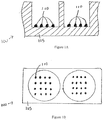
Figures 1A-B show a cross-sectional side view and a top view, respectively, of two wells in a microtiter plate. -
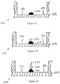
Figures 2A-C show a series of cross-sectional side views of a well in a microtiter plate during a known method of conducting an ELISA. -
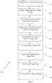
Figure 3 shows a method of preparing in-well calibration features in accordance with some embodiments. -
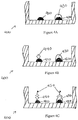
Figures 4A-C show a series of cross-sectional side views of a well in a microtiter plate during a method of conducting an ELISA in accordance with some embodiments. -
Figure 5 shows a cross-sectional side view of a well in a microtiter plate with a number of printed features in accordance with some embodiments. - The invention provides a method for detecting an antigen in a sample, the method comprising:
- printing a plurality of capture antibody features in a well of a testing substrate,
- printing a calibration compound of known concentration on one of the capture antibody features in the well of the testing substrate,
- wherein the calibration compound of known concentration is capable of binding to the capture antibody feature,
- wherein at least one capture antibody feature in the well of the testing substrate does not have a calibration compound of known concentration printed onto the at least one capture antibody feature and is capable of binding to the antigen in the sample, and
- adding the sample to the well of the testing substrate,
- wherein the calibration compound and the antigen are each capable of binding to a same enzyme linked detect antibody.
-
Figure 1A shows an illustration of a cross-sectional side view of two wells in amicrotiter plate 100. In one illustrative implementation, the well substrate is formed of apolystyrene base 105. Other potential substrate materials include, but are not limited to, nitrocellulose, glass, and other plastic materials.Figure 1B shows an illustration of a top view of two wells in amicrotiter plate 100. During the preparation of a microtiter plate for use in biochemical analysis, many different capture antibody "features" 110 are printed in the well and adhere to thepolystyrene base 105. As used herein, "features" can have different shapes, such as, for example, a rounded shape. The assay substrate can be, for example, a 96-well microtiter plate. The features can be, for example, about 300 µm to about 500 µm in diameter. -
Figures 2A-C show a series ofcross-sectional side views 200 of a well 205 during a known method of conducting an ELISA. After thecapture antibody feature 210 has been printed onto the bottom of thewell 205, a blocking material is added to the well to blockplate binding sites 215 that remain on theplate 200. This prevents non-selective binding of sample antigens to the base of the well during the ELISA, which would give false readings. Second, an antigen-containing sample is added to the well.Figure 2B shows the antigen 220 binding to thecapture antibody feature 210. Third, the well is washed so that unbound antigen is removed. Fourth, enzyme-linked detect antibodies are added.Figure 2C shows the enzyme-linkeddetect antibody 230 binding to the antigen 220. The well is then washed so that unbound antibody-enzyme conjugates are removed. Next, a substance is applied which converts the enzyme into a detectable signal, such as a color, fluorescent, or electrochemical signal. Finally, the absorbency, fluorescence, or electrochemical signal of the well is measured and compared with a standard to determine the presence and quantity of the sample antigen. A standard can be generated by printing calibration features with a known concentration of antigen in wells that are separate from the wells that receive patient samples. - Such an approach involves comparing standard results and sample results from different wells. Signal variability, such as fluorescence variability, and well-to-well variability in the separate wells can decrease the accuracy and reliability of test results.
-
Figure 4A shows a cross-sectional side view of one plate well with twocapture antibody features calibration feature 430 printed on top ofcapture antibody feature 420. Thecalibration feature 430 is in the same well as thecapture antibody feature 410 that will bind to the antigen-containing sample.Figure 3 shows amethod 300 of printing in-well calibration features on a microtiter plate in accordance with some embodiments.Method 300 reduces or eliminates the inaccuracy that can result from signal variability and well-to-well variability by printing a calibration feature with a known amount of antigen in the same well as the capture antibody feature that binds to antigen-containing samples. Not only doesmethod 300 reduce the variance of assay results, it also increases throughput, as all the wells of a plate can be used to analyze patient samples. - Suitable samples include proteomic samples such as, for example, from cell lysates, cell supernatants, plasma, serum, or other biological fluids. As used herein, a "target plate" is a plate that is to be prepared (e.g., printed, blocked, and processed for later usage) for a particular set of analyses. A "source plate" is a plate that has a supply of the material to be printed onto a target plate. For example, the wells of a source plate can be filled with various types of antibodies that are to be printed onto target plates. In accordance with
method 300, the source plate is prepared for the printing process (step 310). This can include filling the wells of the source plate with the desired material to be printed onto the target plate. Next, the target plate is prepared for printing (step 320). This can include washing and/or performing other surface treatments to enable the material to be printed to properly adhere to the bottom surface of the plate well. - The source and target plates are then fit into a printing apparatus (e.g., a 2470 Arrayer available from Aushon Biosystems, Inc. of Billerica, MA) (step 330). Capture antibody features are printed in the wells of the target plate (step 340). Next, calibration features with a known concentration of an antigen are precisely printed onto the capture antibody features (step 350). The known concentration of an antigen ranges from the order of femtogram (10-15 g) per milliliter to milligram (10-3 g) per milliliter. Implementations of the invention using the 2470 Arrayer, independent of the arrayer's pin size, can achieve precise printing of the calibration features onto the capture antibody features, such that the positional misalignment between an outer edge of the calibration features and an outer edge of the capture antibody features is about 4 µm or less. Other implementations of the invention can tolerate positional misalignments between an outer edge of the calibration features and an outer edge of the capture antibody features of greater than about 4 µm, depending on the size of the features. For example, when printing features are in the range of about 120 µm to about 240 µm in diameter, positional misalignment between an outer edge of the calibration features and an outer edge of the capture antibody features of about 10 µm can be tolerated.
- As described above,
Figure 4A shows a cross-sectional side view of one plate well with two capture antibody features 410 and 420 and acalibration feature 430 printed on top ofcapture antibody feature 420. Thecalibration feature 430 is in the same well as thecapture antibody feature 410 that will bind to the antigen-containing sample. - The printed target plate is incubated for a period of time (step 360), and a blocking material, which does not react to the capture antibody, is applied to the target plate using known methods (step 370). The blocking material adsorbs to the remaining binding surfaces of the plate and binds to antigens of non-specific interaction, thus reducing background signal. The printed target plate is then dried (step 380). In one illustrative implementation, a blocking material solution is applied to the surfaces of the bottoms of a plurality of wells in a microtiter plate via a spraying process, as described in
U.S. Provisional Patent Application 61/372,552 entitled Method of and System for Applying Blocking Material to Assay Substrates, filed on August 11, 2010 - During the spraying process, an airbrush (e.g., a Paasche Talon model TG0210) is used to apply the blocking material to the bottom surface of the well of the plate. During the spraying step, approximately 10 ml of a blocking material solution is sprayed over the entire surface of the plate. The blocking material is propelled by a compressed air source, e.g., a standard air compressor that supplies clean and dry air, at a pressure of about 138 kPa (20 psig). The flow rate of the airbrush is set to about 10 ml/min. The application of the blocking material reduces or eliminates malformation and/or toppling of features during the addition of blocking material to the microtiter wells. The plates prepared according to the spraying process discussed herein have superior feature uniformity
- The nozzle of the airbrush may be positioned about 15 cm (6 inches) from the surface of the plate, and the airbrush is swept across the entire surface while keeping the nozzle perpendicular to the surface of the plate. In other words, the center of the spray pattern is essentially normal to the surface of the plate. The spraying is continued at least until the level of blocking material in the well covers the printed features 530. After that level of blocking material is achieved, additional blocking material can be added by continuing the spraying process, or, optionally, additional blocking material can be added via micropipette, as described herein.
- The application of the blocking material as described herein can be applied by-hand. In some implementations, the blocking can be applied by automated machinery. For example, after printing, incubating, and drying, the plate can be placed on a conveyor over which is mounted one or more spray nozzles. The rate of the conveyor is controlled to ensure adequate residence time of the plates within the spray pattern of the one or more nozzles. For example, if the total flow rate of all of the nozzles is about 10 ml/min, the conveyor speed can be controlled to provide that at least some portion of the surface of the plate is under the spray pattern for 1 minute. In another illustrative implementation, the plate can be held is a fixed position and an automated arm can direct one or more spray nozzles above the surface of the plate.
- The specific operational parameters provided herein are merely illustrative, and other values are within the scope of the invention. For example, the blocking material flow rate can vary between 5-20 ml/min, the distance between the airbrush flow nozzle and the surface of the plate can vary between 2-41 cm (1-16 inches), and the air pressure can vary between 34-207 kPa (5-30 psig). It is understood that these ranges are merely illustrative and are not intended to be limiting.
- The target plate is then processed for usage or storage using known methods (step 390). For example, the target plate can be incubated at about 4°C overnight. Alternatively, excess blocking material (e.g., the blocking material that has not bound to the bottom of the well) can be removed from the target plate, the plate can then be dried, and then the plate can be placed into a moisture-resistant package for storage. The disclosed method of printing in-well calibration features reduces or eliminates inaccuracy that can result from having the calibration feature printed in a separate well from the capture antibody feature that will bind to the antigen-containing sample. The disclosed method also increases throughput, as all the wells of a plate can be used to analyze patient samples.
- The plates with in-well calibration features can then be used to conduct chemical and/or biological analyses, such as with an ELISA.
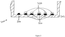
Figure 4B shows a cross-sectional side view of the well after an antigen-containing sample has been added, andpatient antigen 440 binds to thecapture antibody 410. Next, enzyme-linked detect antibodies are added to the well.Figure 4C shows the enzyme-linked detectantibody 450 binding to theantigen 440 andcalibration feature 430. A substance, such as a chemiluminescent substrate solution, is applied to convert the enzyme into a detectable signal. Finally, the signals are measured, and the presence and quantity of the sample antigen is determined using methods known in the art. - In another illustrative example, two or more capture antibody features can be printed on each well, and one or more calibration features of varying antigen concentrations can be printed on each well.
Figure 5 shows a cross-sectional side view of one plate well with capture antibody features 510 and 520 printed at the bottom of thewell 505. Five calibration features 530 with varying concentrations of antigen are precisely printed on top of capture antibody features 520. The series of calibration features with varying concentrations of antigen can be used to generate a standard curve. With the varying concentrations of the calibration features being known, the features produce detectable signals of varying intensity related to the known concentrations. The standard curve can be compared to the signal of the capture antibody feature binding to the antigen-containing test sample to determine the presence and quantity of the sample antigen. The disclosed method reduces or eliminates inaccuracy that can result from having the series of calibration features printed in separate wells from the capture antibody feature that will bind to the antigen-containing sample. It also results in increased throughput and efficiency of assays and other analyses. - The specific operational parameters provided above are merely illustrative, and other values are within the scope of the invention.
- Kits can be made that incorporate the above devices along with any combination of related equipment or reagents, such as reporter reagents or software for reading results of the assay.The methods described above can be used to detect the presence of antigens and proteins in a patient, such as a patient having an autoimmune disease, antibodies to viral diseases, antibodies to bacterial diseases, antibodies to allergic reactions, or antibodies to cancers.
- The terms and expressions that are employed herein are terms of description and not of limitation. There is no intention in the use of such terms and expressions of excluding the equivalents of the feature shown or described, or portions thereof, it being recognized that various modifications are possible within the scope of the invention as claimed.
Claims (7)
- A method for detecting an antigen in a sample, the method comprising:printing a plurality of capture antibody features in a well of a testing substrate,printing a calibration compound of known concentration on one of the capture antibody features in the well of the testing substrate,wherein the calibration compound of known concentration is capable of binding to the capture antibody feature,wherein at least one capture antibody feature in the well of the testing substrate does not have a calibration compound of known concentration printed onto the at least one capture antibody feature and is capable of binding to the antigen in the sample, andadding the sample to the well of the testing substrate,wherein the calibration compound and the antigen are each capable of binding to a same enzyme linked detect antibody.
- The method of claim 1, further comprising printing a plurality of calibration compounds on a respective plurality of capture antibody features, wherein the plurality of calibration compounds includes at least two different known concentrations of the calibration compound.
- The method of claim 1 or claim 2, further comprising, prior to adding the sample to the well of the testing substrate:incubating the printed testing substrate;applying blocking material to the testing substrate;drying the printed testing substrate; andprocessing the printed testing substrate for usage or storage.
- The method of claim 3, wherein the method is used to conduct biochemical analyses.
- The method of claim 4, wherein the calibration compound that is capable of binding to the capture compound is an antigen.
- The method of claim 5, wherein an enzyme-linked immunosorbent assay is conducted.
- The method of claim 6, further comprising:using the results from the at least two different concentrations of the calibration compound that is capable of binding to the capture antibody feature to create a calibration curve;comparing the calibration curve to a signal of a capture antibody feature binding to an antigen-containing test sample; anddetermining the presence and quantity of the antigen in the test sample.
Applications Claiming Priority (2)
| Application Number | Priority Date | Filing Date | Title |
|---|---|---|---|
| US41466310P | 2010-11-17 | 2010-11-17 | |
| PCT/US2011/061184 WO2012068372A1 (en) | 2010-11-17 | 2011-11-17 | Method of and system for printing in-well calibration features |
Publications (3)
| Publication Number | Publication Date |
|---|---|
| EP2640876A1 EP2640876A1 (en) | 2013-09-25 |
| EP2640876A4 EP2640876A4 (en) | 2014-04-16 |
| EP2640876B1 true EP2640876B1 (en) | 2017-03-01 |
Family
ID=46084414
Family Applications (1)
| Application Number | Title | Priority Date | Filing Date |
|---|---|---|---|
| EP11840749.3A Active EP2640876B1 (en) | 2010-11-17 | 2011-11-17 | Method for printing in-well calibration features |
Country Status (6)
| Country | Link |
|---|---|
| US (2) | US20130266969A1 (en) |
| EP (1) | EP2640876B1 (en) |
| JP (1) | JP6203638B2 (en) |
| KR (1) | KR20140063499A (en) |
| CA (1) | CA2818483C (en) |
| WO (1) | WO2012068372A1 (en) |
Families Citing this family (6)
| Publication number | Priority date | Publication date | Assignee | Title |
|---|---|---|---|---|
| GB0913258D0 (en) | 2009-07-29 | 2009-09-02 | Dynex Technologies Inc | Reagent dispenser |
| US9523701B2 (en) | 2009-07-29 | 2016-12-20 | Dynex Technologies, Inc. | Sample plate systems and methods |
| ES2926726T3 (en) | 2011-11-14 | 2022-10-27 | Aushon Biosystems Inc | Systems and methods to improve consistency of assay performance |
| US10562032B2 (en) | 2017-05-26 | 2020-02-18 | Aushon Biosystems, Inc. | Systems and methods for automatic plate washing |
| US11686730B2 (en) | 2020-04-30 | 2023-06-27 | Quanterix Corporation | Quantitative antibody test |
| GB202010627D0 (en) | 2020-07-10 | 2020-08-26 | Qbd (Qs-Ip) Ltd | Blocking method |
Family Cites Families (18)
| Publication number | Priority date | Publication date | Assignee | Title |
|---|---|---|---|---|
| US5395754A (en) * | 1992-07-31 | 1995-03-07 | Hybritech Incorporated | Membrane-based immunoassay method |
| US20040265923A1 (en) * | 2001-05-03 | 2004-12-30 | James Gilmore | Method and apparatus to determine the performance of protein arrays |
| US20030198967A1 (en) * | 2002-04-23 | 2003-10-23 | Matson Robert S. | Multi-functional microarrays and methods |
| US20040049351A1 (en) * | 2002-08-28 | 2004-03-11 | Matson Robert S. | Immunosorbent assay in microarray format |
| US20040121334A1 (en) * | 2002-12-19 | 2004-06-24 | Kimberly-Clark Worldwide, Inc. | Self-calibrated flow-through assay devices |
| US20040229226A1 (en) * | 2003-05-16 | 2004-11-18 | Reddy M. Parameswara | Reducing microarray variation with internal reference spots |
| GB0311902D0 (en) * | 2003-05-22 | 2003-06-25 | Cambridge Life Sciences | Assay method and apparatus |
| FR2864550B1 (en) * | 2003-12-29 | 2006-02-24 | Commissariat Energie Atomique | CHIP OF ANALYSIS WITH STANDARD RANGE, KITS AND METHODS OF ANALYSIS. |
| US20050266398A1 (en) * | 2004-06-01 | 2005-12-01 | Peter Lea | Method and device for rapid detection and quantitation of macro and micro matrices |
| CA2475456A1 (en) * | 2004-07-20 | 2006-01-20 | Biophys, Inc. | Method and device to optimize analyte and antibody substrate binding by least energy adsorption |
| US20060292586A1 (en) * | 2004-12-17 | 2006-12-28 | Schroth Gary P | ID-tag complexes, arrays, and methods of use thereof |
| US20060141527A1 (en) * | 2004-12-29 | 2006-06-29 | Caracci Stephen J | Method for creating a reference region and a sample region on a biosensor and the resulting biosensor |
| AU2005337803B2 (en) * | 2005-10-29 | 2013-04-18 | Bayer Intellectual Property Gmbh | Process for determining one or more analytes in samples of biological origin having complex composition, and use thereof |
| FR2894596B1 (en) * | 2005-12-13 | 2012-08-10 | Centre Nat Rech Scient | PROCESS FOR AUTOCALIBRATION OF BIOPUCES |
| WO2007131103A2 (en) * | 2006-05-03 | 2007-11-15 | Quadraspec, Inc. | Direct printing of patterned hydrophobic wells |
| WO2008007159A1 (en) * | 2006-07-14 | 2008-01-17 | Eötvös Lorand University | Measurement of complement activation products on antigen arrays |
| US9625453B2 (en) * | 2006-11-28 | 2017-04-18 | Pictor Limited | Assay membrane and method of use thereof |
| CA2647953A1 (en) * | 2008-12-29 | 2010-06-29 | Sqi Diagnostics Systems Inc. | Multiplex analyte detection |
-
2011
- 2011-11-17 CA CA2818483A patent/CA2818483C/en active Active
- 2011-11-17 KR KR1020137015223A patent/KR20140063499A/en not_active Application Discontinuation
- 2011-11-17 EP EP11840749.3A patent/EP2640876B1/en active Active
- 2011-11-17 WO PCT/US2011/061184 patent/WO2012068372A1/en active Application Filing
- 2011-11-17 JP JP2013540013A patent/JP6203638B2/en not_active Expired - Fee Related
-
2012
- 2012-09-28 US US13/630,917 patent/US20130266969A1/en not_active Abandoned
-
2017
- 2017-12-22 US US15/852,939 patent/US20180120310A1/en not_active Abandoned
Non-Patent Citations (1)
| Title |
|---|
| LING MICHAEL M ET AL: "MULTIPLEXING MOLECULAR DIAGNOSTICS AND IMMUNOASSAYS USING EMERGING MICROARRAY TECHNOLOGIES", EXPERT REVIEW OF MOLECULAR DIAGNOSTICS, FUTURE DRUGS, LONDON, GB, vol. 7, no. 1, 1 January 2007 (2007-01-01), pages 87 - 98, XP009080968, ISSN: 1473-7159, DOI: 10.1586/14737159.7.1.87 * |
Also Published As
| Publication number | Publication date |
|---|---|
| WO2012068372A1 (en) | 2012-05-24 |
| US20180120310A1 (en) | 2018-05-03 |
| CA2818483A1 (en) | 2012-05-24 |
| JP6203638B2 (en) | 2017-09-27 |
| KR20140063499A (en) | 2014-05-27 |
| EP2640876A1 (en) | 2013-09-25 |
| US20130266969A1 (en) | 2013-10-10 |
| CA2818483C (en) | 2020-12-15 |
| JP2013543981A (en) | 2013-12-09 |
| EP2640876A4 (en) | 2014-04-16 |
Similar Documents
| Publication | Publication Date | Title |
|---|---|---|
| US20180120310A1 (en) | Method of and System for Printing In-Well Calibration Features | |
| JP5043186B2 (en) | Fine channel type sensor composite structure | |
| US20220048025A1 (en) | Systems and methods to enhance consistency of assay performance | |
| JP2009503447A (en) | Label-free high-throughput biomolecule screening system and method | |
| JP2006215017A (en) | Device for discontinuous immunoassay and method of immunoassay utilizing it | |
| JP4253695B2 (en) | Substance determination method and substance determination device | |
| JP2013543981A5 (en) | ||
| US20140134652A1 (en) | Methods of and Systems for Improved Detection Sensitivity of Assays | |
| EP1512012B1 (en) | Biomolecular kinetics method using a flow-through microarray | |
| EP3679856A1 (en) | Chromatographic strip comprising multiple test lines, diagnostic kit comprising same, and qualitative, semi-quantitative or quantitative analysis method comprising multiple competitive reaction measurement steps | |
| US20100075860A1 (en) | Microassay with internal referencing | |
| EP4080212A2 (en) | Immunochromatographic strip and kit, and competitive immunochromatographic analysis method using same | |
| EP2603325B1 (en) | Method of and system for applying blocking material to assay substrates | |
| US7846713B2 (en) | Calibrating microarrays | |
| ITRM980266A1 (en) | GLOBAL SYSTEM INCLUDING COMPACT AND ROBOTIZED INSTRUMENT AND SPECIAL REACTIVE CHAMBERS FOR COMPLETE DETERMINATION |
Legal Events
| Date | Code | Title | Description |
|---|---|---|---|
| PUAI | Public reference made under article 153(3) epc to a published international application that has entered the european phase |
Free format text: ORIGINAL CODE: 0009012 |
|
| 17P | Request for examination filed |
Effective date: 20130522 |
|
| AK | Designated contracting states |
Kind code of ref document: A1 Designated state(s): AL AT BE BG CH CY CZ DE DK EE ES FI FR GB GR HR HU IE IS IT LI LT LU LV MC MK MT NL NO PL PT RO RS SE SI SK SM TR |
|
| AX | Request for extension of the european patent |
Extension state: BA ME |
|
| A4 | Supplementary search report drawn up and despatched |
Effective date: 20140319 |
|
| RIC1 | Information provided on ipc code assigned before grant |
Ipc: C40B 30/04 20060101AFI20140313BHEP |
|
| 17Q | First examination report despatched |
Effective date: 20150504 |
|
| REG | Reference to a national code |
Ref country code: DE Ref legal event code: R079 Ref document number: 602011035542 Country of ref document: DE Free format text: PREVIOUS MAIN CLASS: C40B0030040000 Ipc: B01L0003000000 |
|
| GRAP | Despatch of communication of intention to grant a patent |
Free format text: ORIGINAL CODE: EPIDOSNIGR1 |
|
| RIC1 | Information provided on ipc code assigned before grant |
Ipc: G01N 33/543 20060101ALI20160520BHEP Ipc: B01L 3/00 20060101AFI20160520BHEP |
|
| INTG | Intention to grant announced |
Effective date: 20160624 |
|
| GRAJ | Information related to disapproval of communication of intention to grant by the applicant or resumption of examination proceedings by the epo deleted |
Free format text: ORIGINAL CODE: EPIDOSDIGR1 |
|
| INTC | Intention to grant announced (deleted) | ||
| GRAP | Despatch of communication of intention to grant a patent |
Free format text: ORIGINAL CODE: EPIDOSNIGR1 |
|
| INTG | Intention to grant announced |
Effective date: 20160922 |
|
| GRAS | Grant fee paid |
Free format text: ORIGINAL CODE: EPIDOSNIGR3 |
|
| GRAA | (expected) grant |
Free format text: ORIGINAL CODE: 0009210 |
|
| AK | Designated contracting states |
Kind code of ref document: B1 Designated state(s): AL AT BE BG CH CY CZ DE DK EE ES FI FR GB GR HR HU IE IS IT LI LT LU LV MC MK MT NL NO PL PT RO RS SE SI SK SM TR |
|
| AX | Request for extension of the european patent |
Extension state: BA ME |
|
| REG | Reference to a national code |
Ref country code: GB Ref legal event code: FG4D |
|
| REG | Reference to a national code |
Ref country code: CH Ref legal event code: EP Ref country code: AT Ref legal event code: REF Ref document number: 870639 Country of ref document: AT Kind code of ref document: T Effective date: 20170315 |
|
| REG | Reference to a national code |
Ref country code: IE Ref legal event code: FG4D |
|
| REG | Reference to a national code |
Ref country code: DE Ref legal event code: R096 Ref document number: 602011035542 Country of ref document: DE |
|
| REG | Reference to a national code |
Ref country code: NL Ref legal event code: FP |
|
| REG | Reference to a national code |
Ref country code: SE Ref legal event code: TRGR |
|
| REG | Reference to a national code |
Ref country code: CH Ref legal event code: NV Representative=s name: MICHELI AND CIE SA, CH |
|
| REG | Reference to a national code |
Ref country code: LT Ref legal event code: MG4D |
|
| REG | Reference to a national code |
Ref country code: AT Ref legal event code: MK05 Ref document number: 870639 Country of ref document: AT Kind code of ref document: T Effective date: 20170301 |
|
| PG25 | Lapsed in a contracting state [announced via postgrant information from national office to epo] |
Ref country code: NO Free format text: LAPSE BECAUSE OF FAILURE TO SUBMIT A TRANSLATION OF THE DESCRIPTION OR TO PAY THE FEE WITHIN THE PRESCRIBED TIME-LIMIT Effective date: 20170601 Ref country code: LT Free format text: LAPSE BECAUSE OF FAILURE TO SUBMIT A TRANSLATION OF THE DESCRIPTION OR TO PAY THE FEE WITHIN THE PRESCRIBED TIME-LIMIT Effective date: 20170301 Ref country code: HR Free format text: LAPSE BECAUSE OF FAILURE TO SUBMIT A TRANSLATION OF THE DESCRIPTION OR TO PAY THE FEE WITHIN THE PRESCRIBED TIME-LIMIT Effective date: 20170301 Ref country code: GR Free format text: LAPSE BECAUSE OF FAILURE TO SUBMIT A TRANSLATION OF THE DESCRIPTION OR TO PAY THE FEE WITHIN THE PRESCRIBED TIME-LIMIT Effective date: 20170602 |
|
| PG25 | Lapsed in a contracting state [announced via postgrant information from national office to epo] |
Ref country code: BG Free format text: LAPSE BECAUSE OF FAILURE TO SUBMIT A TRANSLATION OF THE DESCRIPTION OR TO PAY THE FEE WITHIN THE PRESCRIBED TIME-LIMIT Effective date: 20170601 Ref country code: LV Free format text: LAPSE BECAUSE OF FAILURE TO SUBMIT A TRANSLATION OF THE DESCRIPTION OR TO PAY THE FEE WITHIN THE PRESCRIBED TIME-LIMIT Effective date: 20170301 Ref country code: ES Free format text: LAPSE BECAUSE OF FAILURE TO SUBMIT A TRANSLATION OF THE DESCRIPTION OR TO PAY THE FEE WITHIN THE PRESCRIBED TIME-LIMIT Effective date: 20170301 Ref country code: RS Free format text: LAPSE BECAUSE OF FAILURE TO SUBMIT A TRANSLATION OF THE DESCRIPTION OR TO PAY THE FEE WITHIN THE PRESCRIBED TIME-LIMIT Effective date: 20170301 Ref country code: AT Free format text: LAPSE BECAUSE OF FAILURE TO SUBMIT A TRANSLATION OF THE DESCRIPTION OR TO PAY THE FEE WITHIN THE PRESCRIBED TIME-LIMIT Effective date: 20170301 |
|
| PG25 | Lapsed in a contracting state [announced via postgrant information from national office to epo] |
Ref country code: EE Free format text: LAPSE BECAUSE OF FAILURE TO SUBMIT A TRANSLATION OF THE DESCRIPTION OR TO PAY THE FEE WITHIN THE PRESCRIBED TIME-LIMIT Effective date: 20170301 Ref country code: SK Free format text: LAPSE BECAUSE OF FAILURE TO SUBMIT A TRANSLATION OF THE DESCRIPTION OR TO PAY THE FEE WITHIN THE PRESCRIBED TIME-LIMIT Effective date: 20170301 Ref country code: RO Free format text: LAPSE BECAUSE OF FAILURE TO SUBMIT A TRANSLATION OF THE DESCRIPTION OR TO PAY THE FEE WITHIN THE PRESCRIBED TIME-LIMIT Effective date: 20170301 Ref country code: CZ Free format text: LAPSE BECAUSE OF FAILURE TO SUBMIT A TRANSLATION OF THE DESCRIPTION OR TO PAY THE FEE WITHIN THE PRESCRIBED TIME-LIMIT Effective date: 20170301 |
|
| PG25 | Lapsed in a contracting state [announced via postgrant information from national office to epo] |
Ref country code: PT Free format text: LAPSE BECAUSE OF FAILURE TO SUBMIT A TRANSLATION OF THE DESCRIPTION OR TO PAY THE FEE WITHIN THE PRESCRIBED TIME-LIMIT Effective date: 20170703 Ref country code: SM Free format text: LAPSE BECAUSE OF FAILURE TO SUBMIT A TRANSLATION OF THE DESCRIPTION OR TO PAY THE FEE WITHIN THE PRESCRIBED TIME-LIMIT Effective date: 20170301 Ref country code: PL Free format text: LAPSE BECAUSE OF FAILURE TO SUBMIT A TRANSLATION OF THE DESCRIPTION OR TO PAY THE FEE WITHIN THE PRESCRIBED TIME-LIMIT Effective date: 20170301 Ref country code: IS Free format text: LAPSE BECAUSE OF FAILURE TO SUBMIT A TRANSLATION OF THE DESCRIPTION OR TO PAY THE FEE WITHIN THE PRESCRIBED TIME-LIMIT Effective date: 20170701 |
|
| REG | Reference to a national code |
Ref country code: DE Ref legal event code: R097 Ref document number: 602011035542 Country of ref document: DE |
|
| PLBE | No opposition filed within time limit |
Free format text: ORIGINAL CODE: 0009261 |
|
| STAA | Information on the status of an ep patent application or granted ep patent |
Free format text: STATUS: NO OPPOSITION FILED WITHIN TIME LIMIT |
|
| PG25 | Lapsed in a contracting state [announced via postgrant information from national office to epo] |
Ref country code: DK Free format text: LAPSE BECAUSE OF FAILURE TO SUBMIT A TRANSLATION OF THE DESCRIPTION OR TO PAY THE FEE WITHIN THE PRESCRIBED TIME-LIMIT Effective date: 20170301 |
|
| 26N | No opposition filed |
Effective date: 20171204 |
|
| PG25 | Lapsed in a contracting state [announced via postgrant information from national office to epo] |
Ref country code: SI Free format text: LAPSE BECAUSE OF FAILURE TO SUBMIT A TRANSLATION OF THE DESCRIPTION OR TO PAY THE FEE WITHIN THE PRESCRIBED TIME-LIMIT Effective date: 20170301 |
|
| PG25 | Lapsed in a contracting state [announced via postgrant information from national office to epo] |
Ref country code: MC Free format text: LAPSE BECAUSE OF FAILURE TO SUBMIT A TRANSLATION OF THE DESCRIPTION OR TO PAY THE FEE WITHIN THE PRESCRIBED TIME-LIMIT Effective date: 20170301 |
|
| PG25 | Lapsed in a contracting state [announced via postgrant information from national office to epo] |
Ref country code: LU Free format text: LAPSE BECAUSE OF NON-PAYMENT OF DUE FEES Effective date: 20171117 |
|
| REG | Reference to a national code |
Ref country code: FR Ref legal event code: ST Effective date: 20180731 Ref country code: BE Ref legal event code: MM Effective date: 20171130 |
|
| PG25 | Lapsed in a contracting state [announced via postgrant information from national office to epo] |
Ref country code: MT Free format text: LAPSE BECAUSE OF NON-PAYMENT OF DUE FEES Effective date: 20171117 |
|
| PG25 | Lapsed in a contracting state [announced via postgrant information from national office to epo] |
Ref country code: FR Free format text: LAPSE BECAUSE OF NON-PAYMENT OF DUE FEES Effective date: 20171130 |
|
| PG25 | Lapsed in a contracting state [announced via postgrant information from national office to epo] |
Ref country code: BE Free format text: LAPSE BECAUSE OF NON-PAYMENT OF DUE FEES Effective date: 20171130 |
|
| PG25 | Lapsed in a contracting state [announced via postgrant information from national office to epo] |
Ref country code: HU Free format text: LAPSE BECAUSE OF FAILURE TO SUBMIT A TRANSLATION OF THE DESCRIPTION OR TO PAY THE FEE WITHIN THE PRESCRIBED TIME-LIMIT; INVALID AB INITIO Effective date: 20111117 |
|
| PG25 | Lapsed in a contracting state [announced via postgrant information from national office to epo] |
Ref country code: CY Free format text: LAPSE BECAUSE OF NON-PAYMENT OF DUE FEES Effective date: 20170301 |
|
| PG25 | Lapsed in a contracting state [announced via postgrant information from national office to epo] |
Ref country code: MK Free format text: LAPSE BECAUSE OF FAILURE TO SUBMIT A TRANSLATION OF THE DESCRIPTION OR TO PAY THE FEE WITHIN THE PRESCRIBED TIME-LIMIT Effective date: 20170301 |
|
| PGFP | Annual fee paid to national office [announced via postgrant information from national office to epo] |
Ref country code: IE Payment date: 20191127 Year of fee payment: 9 Ref country code: DE Payment date: 20191127 Year of fee payment: 9 Ref country code: FI Payment date: 20191127 Year of fee payment: 9 Ref country code: SE Payment date: 20191127 Year of fee payment: 9 Ref country code: NL Payment date: 20191126 Year of fee payment: 9 |
|
| PGFP | Annual fee paid to national office [announced via postgrant information from national office to epo] |
Ref country code: IT Payment date: 20191125 Year of fee payment: 9 |
|
| PG25 | Lapsed in a contracting state [announced via postgrant information from national office to epo] |
Ref country code: TR Free format text: LAPSE BECAUSE OF FAILURE TO SUBMIT A TRANSLATION OF THE DESCRIPTION OR TO PAY THE FEE WITHIN THE PRESCRIBED TIME-LIMIT Effective date: 20170301 |
|
| PGFP | Annual fee paid to national office [announced via postgrant information from national office to epo] |
Ref country code: CH Payment date: 20191203 Year of fee payment: 9 |
|
| PGFP | Annual fee paid to national office [announced via postgrant information from national office to epo] |
Ref country code: GB Payment date: 20191127 Year of fee payment: 9 |
|
| PG25 | Lapsed in a contracting state [announced via postgrant information from national office to epo] |
Ref country code: AL Free format text: LAPSE BECAUSE OF FAILURE TO SUBMIT A TRANSLATION OF THE DESCRIPTION OR TO PAY THE FEE WITHIN THE PRESCRIBED TIME-LIMIT Effective date: 20170301 |
|
| REG | Reference to a national code |
Ref country code: DE Ref legal event code: R119 Ref document number: 602011035542 Country of ref document: DE |
|
| REG | Reference to a national code |
Ref country code: FI Ref legal event code: MAE |
|
| REG | Reference to a national code |
Ref country code: SE Ref legal event code: EUG |
|
| REG | Reference to a national code |
Ref country code: CH Ref legal event code: PL |
|
| REG | Reference to a national code |
Ref country code: NL Ref legal event code: MM Effective date: 20201201 |
|
| GBPC | Gb: european patent ceased through non-payment of renewal fee |
Effective date: 20201117 |
|
| PG25 | Lapsed in a contracting state [announced via postgrant information from national office to epo] |
Ref country code: FI Free format text: LAPSE BECAUSE OF NON-PAYMENT OF DUE FEES Effective date: 20201117 |
|
| PG25 | Lapsed in a contracting state [announced via postgrant information from national office to epo] |
Ref country code: LI Free format text: LAPSE BECAUSE OF NON-PAYMENT OF DUE FEES Effective date: 20201130 Ref country code: SE Free format text: LAPSE BECAUSE OF NON-PAYMENT OF DUE FEES Effective date: 20201118 Ref country code: NL Free format text: LAPSE BECAUSE OF NON-PAYMENT OF DUE FEES Effective date: 20201201 Ref country code: CH Free format text: LAPSE BECAUSE OF NON-PAYMENT OF DUE FEES Effective date: 20201130 |
|
| PG25 | Lapsed in a contracting state [announced via postgrant information from national office to epo] |
Ref country code: IT Free format text: LAPSE BECAUSE OF NON-PAYMENT OF DUE FEES Effective date: 20201117 Ref country code: IE Free format text: LAPSE BECAUSE OF NON-PAYMENT OF DUE FEES Effective date: 20201117 |
|
| PG25 | Lapsed in a contracting state [announced via postgrant information from national office to epo] |
Ref country code: DE Free format text: LAPSE BECAUSE OF NON-PAYMENT OF DUE FEES Effective date: 20210601 Ref country code: GB Free format text: LAPSE BECAUSE OF NON-PAYMENT OF DUE FEES Effective date: 20201117 |