KR20140056262A - Leaf spring and compressor with leaf spring - Google Patents
Leaf spring and compressor with leaf spring Download PDFInfo
- Publication number
- KR20140056262A KR20140056262A KR1020147003274A KR20147003274A KR20140056262A KR 20140056262 A KR20140056262 A KR 20140056262A KR 1020147003274 A KR1020147003274 A KR 1020147003274A KR 20147003274 A KR20147003274 A KR 20147003274A KR 20140056262 A KR20140056262 A KR 20140056262A
- Authority
- KR
- South Korea
- Prior art keywords
- compressor
- leaf spring
- leaf springs
- spacer
- leaf
- Prior art date
Links
Images


Classifications
-
- F—MECHANICAL ENGINEERING; LIGHTING; HEATING; WEAPONS; BLASTING
- F04—POSITIVE - DISPLACEMENT MACHINES FOR LIQUIDS; PUMPS FOR LIQUIDS OR ELASTIC FLUIDS
- F04B—POSITIVE-DISPLACEMENT MACHINES FOR LIQUIDS; PUMPS
- F04B9/00—Piston machines or pumps characterised by the driving or driven means to or from their working members
- F04B9/02—Piston machines or pumps characterised by the driving or driven means to or from their working members the means being mechanical
- F04B9/06—Piston machines or pumps characterised by the driving or driven means to or from their working members the means being mechanical the means including spring- or weight-loaded lost-motion devices
-
- F—MECHANICAL ENGINEERING; LIGHTING; HEATING; WEAPONS; BLASTING
- F04—POSITIVE - DISPLACEMENT MACHINES FOR LIQUIDS; PUMPS FOR LIQUIDS OR ELASTIC FLUIDS
- F04B—POSITIVE-DISPLACEMENT MACHINES FOR LIQUIDS; PUMPS
- F04B35/00—Piston pumps specially adapted for elastic fluids and characterised by the driving means to their working members, or by combination with, or adaptation to, specific driving engines or motors, not otherwise provided for
- F04B35/04—Piston pumps specially adapted for elastic fluids and characterised by the driving means to their working members, or by combination with, or adaptation to, specific driving engines or motors, not otherwise provided for the means being electric
- F04B35/045—Piston pumps specially adapted for elastic fluids and characterised by the driving means to their working members, or by combination with, or adaptation to, specific driving engines or motors, not otherwise provided for the means being electric using solenoids
-
- F—MECHANICAL ENGINEERING; LIGHTING; HEATING; WEAPONS; BLASTING
- F04—POSITIVE - DISPLACEMENT MACHINES FOR LIQUIDS; PUMPS FOR LIQUIDS OR ELASTIC FLUIDS
- F04B—POSITIVE-DISPLACEMENT MACHINES FOR LIQUIDS; PUMPS
- F04B39/00—Component parts, details, or accessories, of pumps or pumping systems specially adapted for elastic fluids, not otherwise provided for in, or of interest apart from, groups F04B25/00 - F04B37/00
- F04B39/10—Adaptations or arrangements of distribution members
- F04B39/1073—Adaptations or arrangements of distribution members the members being reed valves
-
- F—MECHANICAL ENGINEERING; LIGHTING; HEATING; WEAPONS; BLASTING
- F16—ENGINEERING ELEMENTS AND UNITS; GENERAL MEASURES FOR PRODUCING AND MAINTAINING EFFECTIVE FUNCTIONING OF MACHINES OR INSTALLATIONS; THERMAL INSULATION IN GENERAL
- F16F—SPRINGS; SHOCK-ABSORBERS; MEANS FOR DAMPING VIBRATION
- F16F1/00—Springs
- F16F1/02—Springs made of steel or other material having low internal friction; Wound, torsion, leaf, cup, ring or the like springs, the material of the spring not being relevant
- F16F1/32—Belleville-type springs
- F16F1/324—Belleville-type springs characterised by having tongues or arms directed in a generally radial direction, i.e. diaphragm-type springs
- F16F1/326—Belleville-type springs characterised by having tongues or arms directed in a generally radial direction, i.e. diaphragm-type springs with a spiral-like appearance
Abstract
본 발명은 컴프레서 리프 스프링들, 특히 선형 컴프레서 리프 스프링들에 관한 것이고; 리프 스프링들은 적어도 한 쌍의 판 스프링(2)들 사이에 배치된 적어도 하나의 스페이서(3)를 포함하고, 판 스프링(2) 각각은 적어도 하나의 외측링(21), 적어도 하나의 내측링(22) 및 내측링(22)에 외측림(21)을 연결하는 적어도 하나의 연결 연장부(23)에 의해 구성되며; 본 발명에 따라, 적어도 하나의 스페이서(3)에 의해 한정된 적어도 한 쌍의 외측림(21)들 사이에 위치한 물리적 접촉부의 적어도 하나의 구역, 적어도 하나의 스페이서(3)에 의해 한정된 적어도 한 쌍의 내측림(22)들 사이에 위치한 물리적 접촉부의 적어도 하나의 구역, 및 인접하게 배열된 적어도 2개의 연결 연장부(23)들 사이에 위치한 물리적 접촉부의 적어도 하나의 자유 구역이 한정된다.The invention relates to compressor leaf springs, in particular to linear compressor leaf springs; The leaf springs comprise at least one spacer (3) arranged between at least one pair of leaf springs (2), each leaf spring (2) comprising at least one outer ring (21), at least one inner ring 22) and at least one connection extension (23) connecting the outer rim (21) to the inner ring (22); According to the invention there is provided at least one zone of physical contact located between at least one pair of lateral rims 21 defined by at least one spacer 3, at least one zone of at least one pair of spacers 3 defined by at least one spacer 3, At least one free region of the physical contact located between the inner rims 22 and at least one region of the physical contact located between the at least two connection extensions 23 arranged adjacently is defined.
Description
본 발명은 컴프레서 리프 스프링, 특히, 선형 컴프레서 리프 스프링, 및 리프 스프링을 구비한 컴프레서, 특히 적어도 하나의 선형 컴프레서 메커니즘에 상호작용하게 배치된 적어도 2개의 리프 스프링들을 구비한 선형 컴프레서에 관한 것이다.The invention relates to a compressor leaf spring, in particular a linear compressor leaf spring, and a compressor with a leaf spring, in particular a linear compressor with at least two leaf springs disposed in interaction with at least one linear compressor mechanism.
기술 분야에서 통상의 지식을 가진 자에게 꽤 알려진 바와 같이, 컴프레서는 특정한 작동 유체의 압력을 상승시킬 수 있는 기계(또는 전기 기계) 장치를 포함하여, 일단 "가압된" 상기 작동 유체가 상이한 적용에 사용될 수 있다.As is well known to those skilled in the art, the compressor includes a mechanical (or electromechanical) device that can raise the pressure of a particular working fluid so that once the "pressurized & Can be used.
현재 최신 기술에 속하는 컴프레서의 형태들 중에서, 왕복 컴프레서가 알려진다. 이러한 컴프레서들은 언급된 작동 유체가 일시적으로 배치되는 "챔버"의 체적을 변경함으로써 작동 유체의 압력을 상승시킬 수 있다. 이런 점에서, 왕복 컴프레서는 "챔버"의 체적 변경을 촉진하기 위한 실린더-피스톤 어셈블리를 이용하고, 여기서 상기 작동 유체는 상기 실린더 내에서 축방향으로 운동하는 피스톤이 이동됨에 따라 내측 체적이 변경되는, 이러한 챔버 자체를 한정하는 실린더의 내측부에 일시적으로 배치된다. 피스톤 운동이 전기 모터에 의해 일반적으로 한정된, 구동원에 의해 일반적으로 도입된다.Of the types of compressors currently in the state of the art, reciprocating compressors are known. These compressors can increase the pressure of the working fluid by changing the volume of the "chamber " in which the working fluid is temporarily disposed. In this regard, the reciprocating compressor utilizes a cylinder-piston assembly for facilitating volume change of the "chamber ", wherein the working fluid has an inner volume that varies as the piston axially moving within the cylinder is moved, And is temporarily disposed on the inner side of the cylinder defining the chamber itself. Piston motion is generally introduced by a drive source, generally defined by an electric motor.
일반적으로, 왕복 컴프레서에 사용되는 전기 모터의 형태는 결국 컴프레서 명명법을 한정한다. 이런 점에서, 선형 컴프레서들은 선형 전기 모터(정적 스테이터(stator) 및 축방향 동적 커서(cursor)로 구성된 모터)에 기초하여 알려진다.Generally, the form of the electric motor used in the reciprocating compressor ultimately limits the compressor nomenclature. In this regard, linear compressors are known based on linear electric motors (motors comprised of static stator and axial dynamic cursor).
선형 컴프레서는 또한 공진 진동 메커니즘(resonant oscillatory mechanism)(공진 스프링-질량 어셈블리(resonant spring-mass assembly))에 기초할 수 있다는 것이 기술 분야에서 통상의 지식을 가진 자에게 추가로 알려진다. 특별한 문헌 및 특허 문서들(예를 들어, 문서 PI 0601645-6)에서 한정된 바와 같이, 공진 진동 메커니즘에 기초한 선형 컴프레서는 선형 모터 및 피스톤을 포함하고, 이 모두는 기능적으로 공진 스프링을 통해 상호 간에 상호연결된다.It is further known to those skilled in the art that linear compressors may also be based on resonant oscillatory mechanisms (resonant spring-mass assemblies). As defined in particular documents and patent documents (e.g. document PI 0601645-6), linear compressors based on resonant vibration mechanisms include linear motors and pistons, all of which are functionally interconnected via resonant springs .
이런 점에서, 최신 기술은 또한 공진 진동 메커니즘에 기초한 선형 컴프레서의 작동 실시예들을 제공한다. 이런 실시예들 중 하나는 2010년 12월 27일의 (현재 비공개 단계 중인) 브라질 문서 018100049527호(출원번호)에서 설명된다. 본 문서는 (공진 진동 어셈블리에 축방향 유연성을 제공할 수 있는) 중간체 내에 배열된 공진 진동 어셈블리(선형 모터, 공진 스프링 및 피스톤으로 이루어진 기능 배열체)를 포함하는 컴프레서를 개시한다. 추가로 본 문서에 따라, 공진 진동 어셈블리는 패스닝 요소(fastening element)에 의해 중간체에 패스닝된다(fastened). 공진 진동 어셈블리는 중간체 및 상기 진동 공진 어셈블리에 따라 정렬된 적어도 하나의 포지셔너 요소(positioner element)(판 스프링)에 의해 한정된 (중간체 내에서) 반지름방향 포지셔닝(positioning)을 갖는다는 것이 더 공지되었다. 본 문서에서 설명된 바와 같이 포지셔너 요소(판 스프링)는 적어도 하나의 연결 연장부(connection extension)에 의해 상호 간에 상호연결되고 중심이 동일하게 배열된 (상이한 직경들을 갖는) 2개의 링들로 이루어지는 몸체부를 포함한다. 이런 경우에, "외측" 링은 중간체에 패스닝되고, '내측' 링은 공진 스프링에 패스닝된다.In this regard, the state of the art also provides operating embodiments of linear compressors based on resonant vibration mechanisms. One of these embodiments is described in the Brazilian document 018100049527 (application number) of December 27, 2010 (currently in the non-public phase). This document discloses a compressor comprising a resonant vibration assembly (a functional arrangement of a linear motor, a resonant spring, and a piston) arranged in an intermediate (which can provide axial flexibility to the resonant vibration assembly). In addition, according to this document, the resonant vibration assembly is fastened to the intermediate by a fastening element. It is further known that the resonant vibration assembly has radial positioning (within the intermediate) defined by at least one positioner element (leaf spring) aligned with the intermediate and the resonant resonant assembly. As described in this document, the positioner elements (leaf springs) are formed by two ring-shaped body portions (having different diameters) interconnected by at least one connection extension, . In this case, the "outer" ring is fastened to the intermediate and the "inner" ring is fastened to the resonant spring.
물론, 이런 형태의 판 스프링은 단지 예시이고, 즉, 현재 최신 기술은 판 스프링들의 다른 모델 및 구성을 더 제공한다.Of course, this type of leaf spring is merely exemplary, i.e., the current state of the art provides further models and configurations of leaf springs.
현재 최신 기술은 또한 선형 컴프레서의 (공진 진동 어셈블리 및 중간체(또는 쉘) 사이에서 반지름방향 포지셔닝/정렬을 확보하기 위하여) 유사한 적용에 판 스프링들에 대한 대체로서 또는 함께 사용될 수 있거나 사용될 수 없는, 판 리프 스프링들을 제공한다.Current state-of-the-art techniques can also be used as alternatives to or in conjunction with plate springs in similar applications (to ensure radial positioning / alignment between resonant vibration assemblies and intermediates (or shells)) of linear compressors, Leaf springs.
(반드시 선형 컴프레서에 사용되지 않는) 리프 스프링의 실시예는 문서 US 3,786,834호에 설명된다. 본 문서는 판 스프링들, 및 판 스프링들 사이에 배열된 스페이서(spacer)들로 구성된 리프 스프링을 제공한다. 이런 경우에, 스페이서들은 기본적으로 판 스프링들의 형상에 대응되는 형상을 포함하고, 그 사이에서 일 종류의 물리적 커넥터로서 작용하는, 일 스프링으로부터 다른 스프링으로 운동을 전달하는 기능을 갖는다.An embodiment of a leaf spring (not necessarily used in a linear compressor) is described in document US 3,786,834. This document provides leaf springs composed of leaf springs, and spacers arranged between leaf springs. In this case, the spacers basically have the shape corresponding to the shape of the leaf springs and have the function of transferring the movement from one spring to the other, acting as a kind of physical connector therebetween.
(반드시 선형 컴프레서에 사용되지 않는) 빔 스프링(beam spring)의 다른 실시예는 문서 US 5,475,587호에서 설명된다. 본 문서는 또한 유연한 디스크들, 및 유연한 디스크들 사이에 배열된 스페이서들로 구성된 리프 스프링을 제공한다. 이런 경우에, 상기 스페이서들은 유연한 디스크들 사이에서 진동을 감쇠시키는 기능만을 갖고, 이에 따라, 유연한 디스크들에 대한 진동 운동을 나타낼 것 같다.Another embodiment of a beam spring (not necessarily used for linear compressors) is described in document US 5,475,587. The document also provides flexible springs, and leaf springs composed of spacers arranged between flexible disks. In this case, the spacers have only the function of damping vibrations between the flexible disks, and are therefore likely to exhibit vibrational motion on the flexible disks.
또한 현재 최신 기술은 상이한 형태들의 판 리프 스프링들을 포함하지만, (상기에 인용된 2개의 실시예들뿐 아니라) 대부분의 이런 형태의 리프 스프링들은 선형 컴프레서들에 사용된 판 스프링들을 대체할 수 없다. 이런 불가능은 주로 2개의 원인들로 인한 것이고, 즉:Also, current state of the art includes plate leaf springs of different types, but most of these leaf springs (as well as the two embodiments cited above) can not replace leaf springs used in linear compressors. This impossibility is primarily due to two causes, namely:
리프 스프링들의 이러한 예시들은 공진 진동 어셈블리의 적절한 기능에 필요한 반지름방향 강성을 확보할 수 없고, 즉, 선형 컴프레서의 중간체(또는 쉘)와 공진 진동 어셈블리 사이에서 반지름방향 포지셔닝을 확보할 수 없다.These examples of leaf springs can not ensure the radial rigidity required for proper functioning of the resonant vibration assembly, i.e., it can not ensure radial positioning between the intermediate (or shell) of the linear compressor and the resonant vibration assembly.
이러한 리프 스프링들은 스프링의 탄성 영역들을 다른 스프링의 다른 탄성 영역들과 일체형으로(또는 반-일체형으로) 접촉시키는 것을 허용하는 구성을 갖는다. 따라서, 이런 설정들은, 최고 압축의 상태일 때, 판 스프링들이 블로킹할(blocking) 수 있는 것(실질적으로 어셈블리의 탄성 특성을 변경하면서, 스프링(또는 리프 스프링)의 "링크(link)들"이 상호 간에 물리적으로 접촉되는 상태)을 허용하고, 이런 특성은 선형 컴프레서와 같은, 진동 운동에 관련된 적용에서 상당히 바람직하지 않다.These leaf springs have a configuration that allows the elastic regions of the spring to be in one piece (or semi-integrally) contact with the other elastic regions of the other spring. Thus, these settings can be used to determine whether the plate springs can block (when substantially changing the elastic properties of the assembly, the "links" of the spring (or leaf spring) Physical contact with each other), and such characteristics are not highly desirable in applications involving vibratory motion, such as linear compressors.
따라서, 현재 최신 기술은 선형 컴프레서, 특히, 공진 진동 메커니즘에 기초한 선형 컴프레서에 사용될 수 있는 리프 스프링들을 제공하지 않는다.Thus, current state-of-the-art techniques do not provide leaf springs which can be used in linear compressors, in particular linear compressors based on resonant vibration mechanisms.
따라서, 공진 진동 메커니즘에 기초한 선형 컴프레서들에 적용될 수 있는 리프 스프링들을 제공하는 것이 본 발명의 목적들 중 하나이다.It is therefore one of the objects of the present invention to provide leaf springs which can be applied to linear compressors based on a resonant vibration mechanism.
따라서, 쉘(또는 중간체)에 대하여 선형 컴프레서의 공진 진동 어셈블리의 반지름방향 포지셔닝을 확보할 수 있는 리프 스프링들을 제공하는 것이 본 발명의 다른 목적이다.It is therefore a further object of the present invention to provide leaf springs which can ensure radial positioning of the resonant vibration assembly of a linear compressor with respect to the shell (or intermediate).
스페이서(spacer)들이 2개의 인접하게 배열되는 (및 저절로, 이런 스페이서들 중 하나에 의해 상호 간에 이격되는) 판 스프링들의 탄성부들을 기계적으로 격리하는 리프 스프링을 제공하는 것이 본 발명의 또 다른 목적이다.It is a further object of the present invention to provide a leaf spring in which spacers mechanically isolate the resilient portions of the leaf springs in which two adjacently arranged (and spontaneously, spaced apart from each other by one of such spacers) spacers .
선형 컴프레서 특히, 선형 컴프레서의 전체적인 직경의 크기 감소를 가능하게 할 수 있는 리프 스프링을 개시하는 것이 또한 본 발명의 다른 목적이다.It is another object of the present invention to disclose a leaf spring which can enable the reduction of the overall diameter of the linear compressor, in particular of the linear compressor.
여기서 개시되는 본 발명의 이런 및 다른 목적들은 여기서 개시되는 컴프레서를 위한 리프 스프링들에 의해 완전히 달성된다.These and other objects of the invention disclosed herein are fully achieved by leaf springs for a compressor as disclosed herein.
상기 컴프레서 리프 스프링들은 적어도 한 쌍의 판 스프링들 사이에 배열된 적어도 하나의 스페이서를 포함하고, 판 스프링 각각은 적어도 하나의 외측링, 적어도 하나의 내측링 및 내측링에 외측링을 연결할 수 있는 적어도 하나의 연결 연장부로 이루어진다.The compressor leaf springs comprising at least one spacer arranged between at least one pair of leaf springs, each plate spring having at least one outer ring, at least one inner ring and at least one And one connection extension part.
본 발명에 따라, 여기서 보고된 리프 스프링들은 적어도 하나의 스페이서에 의해 한정된 적어도 한 쌍의 외측링들 사이에 위치한 물리적 접촉부의 적어도 하나의 구역, 적어도 하나의 스페이서에 의해 한정된 적어도 한 쌍의 내측링들 사이에 위치한 물리적 접촉부의 적어도 하나의 구역 및 인접하게 배열된 적어도 2개의 연결 연장부들 사이에 위치한 물리적 접촉부의 적어도 하나의 자유 구역을 포함한다. 바람직하게는, 2개의 인접하게 배열된 연결 연장부들 사이에는 전체적으로 물리적 접촉부가 없다. 또한 바람직하게는, 인접하게 배열된 한 쌍의 판 스프링들의 연결 연장부들은 평행하고, 판 스프링은 실질적으로 3개의 연결 연장부들을 포함한다.According to the present invention, the leaf springs reported here comprise at least one zone of physical contact located between at least one pair of outer rings defined by at least one spacer, at least one zone of at least one pair of inner rings At least one free area of physical contact positioned between at least one region of the physical contact positioned between the at least two connection extensions and at least one region of adjacently arranged at least two connection extensions. Preferably, there is no overall physical contact between the two adjacently arranged connection extensions. Also preferably, the connection extensions of the pair of adjacently arranged leaf springs are parallel, and the leaf spring includes substantially three connection extensions.
추가로 본 발명에 따라, 스페이서는 실질적인 환형인 몸체부를 포함한다. 적어도 하나의 스페이서는 판 스프링의 외측링의 치수에 대응되는 치수를 갖고, 적어도 하나의 스페이서는 판 스프링의 내측링의 치수에 대응되는 치수를 갖는다.Further in accordance with the present invention, the spacer includes a substantially annular body portion. The at least one spacer has a dimension corresponding to the dimension of the outer ring of the leaf spring and the at least one spacer has a dimension corresponding to the dimension of the inner ring of the leaf spring.
또한 본 발명은 바람직하게 쉘의 원위단들 중 적어도 하나에 배열된 적어도 2개의 리프 스프링들을 포함하는 공진 진동 메커니즘에 기초한 컴프레서에 관한, (상기에 인용된) 판 리프 스프링들을 구비한 컴프레서를 포함한다. 바람직하게는, 쉘의 원위단들의 각각에 배열된 적어도 하나의 리프 스프링이 제공된다.The invention also includes a compressor with leaf springs (cited hereinabove) for a compressor based on a resonant vibration mechanism, preferably comprising at least two leaf springs arranged on at least one of the distal ends of the shell . Preferably, at least one leaf spring arranged in each of the distal ends of the shell is provided.
임의로, 바람직하게는 중간체의 원위단들 중 적어도 하나에 배열된 적어도 2개의 리프 스프링들을 포함하는 공진 진동 메커니즘에 기초한 컴프레서에 관한, (상기에 인용된) 판 리프 스프링들을 구비한 컴프레서가 제공된다. 바람직하게는, 중간체의 원위단들의 각각에 배열된 적어도 하나의 리프 스프링이 제공된다.Optionally, there is provided a compressor with leaf springs (cited above) for a compressor based on a resonant vibration mechanism comprising at least two leaf springs, preferably arranged on at least one of the distal ends of the intermediate. Preferably, at least one leaf spring arranged in each of the distal ends of the intermediate is provided.
본 발명은 여기서 아래에 나열된 도면들에 기초하여 상세하게 설명될 것이다.
도 1은 (본 발명에 따른) 판 스프링을, 사시도로 도시한다.
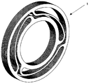
도 2는 (본 발명에 따른) 리프 스프링들을, 사시도로 도시한다.
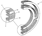
도 3은 (본 발명에 따른) 판 리프 스프링들을, 분해도로 도시한다.
도 4는 (본 발명에 따른) 판 리프 스프링들의 개략 단면도를 도시한다.
도 5는 (본 발명에 따른) 리프 스프링들을 구비한 컴프레서의 실시예를, 개략 단면도로 도시한다.The present invention will now be described in detail based on the drawings listed below.
1 shows a leaf spring (according to the invention) in a perspective view.
Figure 2 shows the leaf springs (according to the invention) in perspective view.
Figure 3 shows plate leaf springs (according to the invention) in an exploded view.
Figure 4 shows a schematic cross-sectional view of leaf leaf springs (according to the invention).
Figure 5 shows a schematic cross section of an embodiment of a compressor with leaf springs (according to the invention).
본 발명의 개념 및 목적에 따라, 본 발명은 인접하게 배열되고 스페이서(spacer)들에 의해 상호 간에 이격되는 판 스프링들로 주로 구성되는 - 공진 진동 메커니즘에 기초한 - 컴프레서에 포함될 수 있는 리프 스프링(1)들을 개시하고, 각 쌍의 판 스프링은 쌍을 일체화시키는 적어도 2개의 스프링들 사이에 스페이서를 제공한다.According to the concept and object of the present invention, the present invention relates to a
또한 본 발명에 따라, 판 스프링들의 각각은 2개의 지지 영역들 및 하나의 축방향 탄성 영역을 한정하고, 판 스프링들의 지지 영역들만이 상호 간에 "상호연결"된다. 따라서, (동일한 것이 리프 스프링들 자체에 순응하면서, 상호 간에 조합될 때) 판 스프링의 축방향 탄성 영역들이 인접하게 배치된 다른 판 스프링들의 축방향 탄성 영역들과의 어떠한 형태의 물리적 접촉부를 나타내지 않을 것이다.Also according to the invention, each of the leaf springs defines two support areas and one axial elastic area, and only the support areas of the leaf springs are "interconnected" with each other. Thus, when the axial elastic regions of the leaf spring do not exhibit any type of physical contact with the axially elastic regions of the adjacent leaf springs (when the same is combined with the leaf springs themselves and are combined with one another) will be.
이런 개념은 전부하 변형(full load deformation)에서, 축방향 탄성 영역들이 없기 때문에, 리프 스프링들은 블로킹(blocking)이 가해지는 것을 회피한다.This concept avoids blocking the leaf springs due to the lack of axial elastic regions in full load deformation.
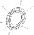
도 1, 도 2, 도 3 및 도 4는 리프 스프링(1)들의 바람직한 구성을 도시한다.Figs. 1, 2, 3 and 4 show preferred configurations of the
이런 도면들에 따라, 상기 리프 스프링(1)들은 스페이서(3)들에 의해 상호 간에 이격된, 제 2 복수 개의 판 스프링들을 포함하는 것이 확인된다.According to these drawings, it is confirmed that the
또한 이런 바람직한 구성에 따라, 판 스프링(2) 각각은 외측링(21), 내측링(22) 및 3개의 연결 연장부(23)들을 포함한다. 이와 관련하여, 외측링(21) 및 내측링(22) 모두는 3개의 연장부(23)들에 의해 상호연결되는, 간단한 환형체들을 포함한다. 동일한 거리로 배열된 - 연장부(23)들의 각각은 - 아치형 원위단들을 갖는 실질적인 반원형 둘레의 돌출부의 형태를 포함한다. 바람직하게는, 리프 스프링(1)을 일체화시키는 판 스프링(2)들의 각각은 금속 합금으로 제조된다.Also according to this preferred configuration, each
이런 구성은 단일 판 스프링(2)이 축방향 유연성이 있을 수 있게 할 수 있고, 즉, 링들(21, 22)은 (상호 간에 대하여) 축방향으로 운동할 수 있고, 이런 운동은 연장 구조물(23)들의 (축 방향으로) 탄성 변형으로부터 기인한다.This arrangement allows the
또한 본 발명의 바람직한 구성에 따라, 스페이서(3)들의 각각은 간단하고 실질적인 환형체를 포함한다. 스페이서들은 2개의 상이한 치수들(둘레들)로 제공된다. 따라서, 판 스프링(2)의 외측링(21)의 치수에 대응되는 치수들을 갖는 스페이서(3)들이 제공되고, 판 스프링(2)의 내측링(22)의 치수에 대응되는 치수들을 갖는 스페이서(3)들이 제공된다. 또한 바람직하게는, 스페이서(3)들이 금속 합금으로 제조된다.Also according to a preferred configuration of the present invention, each of the
이런 구성으로 인해, 적어도 2개의 판 스프링(2)들은 2개의 스페이서(3)들에 의해 평행하게 상호 간에 상호연결된다.With this arrangement, at least two
이런 2개의 스페이서(3)들 중 하나("외측" 스페이서)는 평행하게 배열된 판 스프링(2)들의 2개의 외측링(21)들 사이에 배열된다. 따라서, 이런 스페이서(3)는 한 쌍의 외측링(21)들(의 적어도 하나의 구역) 사이에 위치한 물리적 접촉부를 한정하게 된다.One of these two spacers 3 ("outer" spacers) is arranged between two
다른 스페이서(3)("내측" 스페이서)는 평행하게 배열된 판 스프링(2)들의 2개의 내측링(22)들 사이에 배열된다. 따라서, 이런 스페이서(3)는 한 쌍의 내측링(22)들(의 적어도 하나의 구역) 사이에 위치한 물리적 접촉부를 한정하게 된다.The other spacers 3 ("inner" spacers) are arranged between the two
따라서, 판 스프링(2)들의 연결 연장부(23)들이 상호 간에 자유롭기 때문에, 즉, 연결 연장부(23)들이 인접한 연결 연장부(23)들과의 물리적 접촉부를 제공하지 않고, 이에 따라 어떠한 "블로킹"을 회피하기 때문에, 스페이서(3)들은 접촉 구역들 또는 영역들을 갖는 것이 중요한 (2개의 평행하고 그리고/또는 인접한 판 스프링(2)들 사이에서) 접촉 구역들 또는 영역들만을 한정하게 된다.Thus, since the
바람직하게는, (내측링(22)들 사이에 위치된) 스페이서(3)들은 특히 선형 컴프레서를 일체화하는 다른 요소들을 조립하는 몇몇 단계들 동안에(공진 스프링에 연결 - 로드 및 자석을 연결하는 것을 달성할 요소들을 삽입하는 공정 동안에), 판 스프링(2)들 사이에서 압력에 의해 패스닝된다.Preferably, the spacers 3 (located between the inner rings 22) are designed to be able to be used during several stages of assembling other components, particularly those that incorporate a linear compressor (I.e., during the process of inserting the elements to be cut).
또한 바람직하게는, (외측링(21)들 사이에 위치된) 스페이서(3)들은 특히 (공진 어셈블리가 쉘 내에 위치되고 전체 메커니즘이 가압될 때) 선형 컴프레서를 일체화하는 다른 요소들을 조립하는 몇몇 단계들 동안에, 판 스프링(2)들 사이에서 압력에 의해 패스닝된다.Also preferably, the spacers 3 (located between the outer rings 21) are in some stages (especially when the resonant assembly is located in the shell and when the entire mechanism is pressed) to assemble other elements that integrate the linear compressor The pressure is applied between the
본 발명은 리프 스프링(1)들을 구비한 진동 공진 메커니즘들에 기초한 선형 컴프레서들의 바람직한 구성을 더 포함한다.The invention further comprises a preferred configuration of linear compressors based on vibration resonance mechanisms with leaf springs (1).
일반적으로, 이런 형태의 컴프레서와 적절하게 조합될 때 - 리프 스프링(1)은 - 컴프레서 쉘, 또는 추가로, 중간 요소(2010년 12월 27일의 (현재 비공개 단계 중인) 브라질 문서 018100049527호(출원번호)에서 설명된 요소) 내에서 공진 메커니즘(공진 스프링, 선형 모터 및 실린더-피스톤 어셈블리)의 반지름방향 정렬을 주된 목표로서 유지해야 한다. In general, when properly combined with this type of compressor, the
본 발명의 개념들에 따라, 리프 스프링(1)의 원위단들 중 하나의 판 스프링(2)은 컴프레서의 진동 공진 어셈블리의 공진 스프링의 일종단에 물리적으로 결합된 내측링(22)을 갖는다. 이런 동일한 판 스프링(2)의 외측링(21)은 컴프레서 쉘의 원위단들 중 하나 또는 추가로, (가능하다면) 컴프레서의 중간 요소의 원위단들 중 하나에 물리적으로 결합된다.According to the inventive concepts, one
바람직하게는, 다른 리프 스프링(1)들은 또한 (- 중간 요소 또는 - 쉘 및 공진 스프링의) 컴프레서를 대향하는 원위단들과 조합된다.Preferably, the
내측링(22)들이 외측링(21)들에 대하여 축방향으로 운동할 수 있기에, 리프 스프링(1)들은 컴프레서 쉘(또는 중간 요소)이 계속 정적이면서, 어려움 없이 컴프레서 공진 스프링이 "팽창" 및 "수축"하는 것을 허용한다.The
도 5는 공진 스프링의 종단들을 중간 요소(5)의 종단들에 연결하는, 리프 스프링(1)들을 구비한 선형 컴프레서(4)의 실시예를 도시한다.Fig. 5 shows an embodiment of a linear compressor 4 with
본 발명의 주제의 구체예들의 실시예들을 설명하였더라도, 본 발명의 범위는 그 안에서 추가로 가능한 등가 수단이 포함되면서, 청구항들의 세트들의 내용에 의해 제한되는, 다른 가능한 변경(특히 여기서 처리된 리프 스프링들을 일체화하는 판 스프링들의 구성 변화)을 포함한다는 것이 명확하다.
Although the embodiments of the subject embodiments of the present invention have been described, the scope of the present invention is not limited to the use of other possible modifications, particularly limited by the contents of the sets of claims, A change in the configuration of the leaf springs which integrate the leaf springs).
Claims (11)
적어도 하나의 스페이서(3)에 의해 한정된 적어도 한 쌍의 내측림(21)들 사이에 위치한 물리적 접촉부의 적어도 하나의 구역;
적어도 하나의 스페이서(3)에 의해 한정된 적어도 한 쌍의 내측림(22)들 사이에 위치한 물리적 접촉부의 적어도 하나의 구역; 및
인접하게 배열된 적어도 2개의 연결 연장부(23)들 사이에 위치한 물리적 접촉부의 적어도 하나의 자유 구역을 포함하는 것을 특징으로 하는 컴프레서 리프 스프링.
At least one spacer ring (3) disposed between at least one pair of leaf springs (2), each leaf spring (2) comprising at least one outer ring (21), at least one inner ring At least one connection extension (23) connecting the outer rim (21) to the inner ring (22); In the compressor leaf spring,
At least one region of a physical contact located between at least one pair of inner rims (21) defined by at least one spacer (3);
At least one zone of a physical contact located between at least one pair of inner rims (22) defined by at least one spacer (3); And
Characterized in that it comprises at least one free section of a physical contact situated between at least two adjacently arranged connection extensions (23).
인접하게 배열된 2개의 연결 연장부(23)들 사이에는 물리적 접촉부가 완전히 없는 것을 특징으로 하는 컴프레서 리프 스프링.
The method according to claim 1,
Characterized in that there is no physical contact between the two adjacently arranged two connection extensions (23).
스페이서(3)는 실질적인 환형체를 포함하는 것을 특징으로 하는 컴프레서 리프 스프링.
The method according to claim 1,
Characterized in that the spacer (3) comprises a substantially annular body.
인접하게 배열된 한 쌍의 판 스프링(2)들의 연결 연장부(23)들은 평행한 것을 특징으로 하는 컴프레서 리프 스프링.
The method according to claim 1,
Characterized in that the connecting extensions (23) of a pair of adjacent leaf springs (2) are parallel.
판 스프링(2)은 실질적으로 3개의 연결 연장부(23)들을 포함하는 것을 특징으로 하는 컴프레서 리프 스프링.
The method according to claim 1,
Characterized in that the leaf spring (2) comprises substantially three connection extensions (23).
스페이서(3)는 판 스프링(2)의 외측링(21)의 치수에 대응되는 치수를 갖는 것을 특징으로 하는 컴프레서 리프 스프링.
The method according to claim 1,
Characterized in that the spacer (3) has a dimension corresponding to the dimension of the outer ring (21) of the leaf spring (2).
스페이서(3)는 판 스프링(2)의 내측링(22)의 치수에 대응되는 치수를 갖는 것을 특징으로 하는 컴프레서 리프 스프링.
The method according to claim 1,
Characterized in that the spacer (3) has a dimension corresponding to the dimension of the inner ring (22) of the leaf spring (2).
컴프레서 쉘(4)의 적어도 하나의 원위단에 배열된 적어도 하나의 리프 스프링(1)을 포함하는 것을 특징으로 하는 컴프레서.
A compressor comprising plate leaf springs as defined in any one of claims 1 to 7, and preferably based on a resonant vibration mechanism,
Characterized in that it comprises at least one leaf spring (1) arranged on at least one distal end of the compressor shell (4).
컴프레서 쉘(4)의 원위단들의 각각에 배열된 적어도 하나의 리프 스프링(1)을 포함하는 것을 특징으로 하는 컴프레서.
9. The compressor according to claim 8,
Characterized in that it comprises at least one leaf spring (1) arranged in each of the distal ends of the compressor shell (4).
컴프레서(4)의 중간체(5)의 적어도 하나의 원위단에 배열된 적어도 하나의 리프 스프링(1)을 포함하는 것을 특징으로 하는 컴프레서.
A compressor comprising plate leaf springs as defined in any one of claims 1 to 7, and preferably based on a resonant vibration mechanism,
Characterized in that it comprises at least one leaf spring (1) arranged on at least one distal end of the intermediate body (5) of the compressor (4).
컴프레서(4)의 중간체(5)의 원위단들의 각각에 배열된 적어도 하나의 리프 스프링(1)을 포함하는 것을 특징으로 하는 컴프레서.9. The compressor according to claim 8,
Characterized in that it comprises at least one leaf spring (1) arranged in each of the distal ends of the intermediate (5) of the compressor (4).
Applications Claiming Priority (3)
| Application Number | Priority Date | Filing Date | Title |
|---|---|---|---|
| BRPI1103447-5A BRPI1103447A2 (en) | 2011-07-19 | 2011-07-19 | spring bundle for compressor and spring bundled compressor |
| BRPI1103447-5 | 2011-07-19 | ||
| PCT/BR2012/000209 WO2013010234A1 (en) | 2011-07-19 | 2012-06-21 | Leaf spring and compressor with leaf spring |
Publications (1)
| Publication Number | Publication Date |
|---|---|
| KR20140056262A true KR20140056262A (en) | 2014-05-09 |
Family
ID=46545575
Family Applications (1)
| Application Number | Title | Priority Date | Filing Date |
|---|---|---|---|
| KR1020147003274A KR20140056262A (en) | 2011-07-19 | 2012-06-21 | Leaf spring and compressor with leaf spring |
Country Status (11)
| Country | Link |
|---|---|
| US (1) | US20140241911A1 (en) |
| EP (1) | EP2734730B1 (en) |
| JP (1) | JP2014521006A (en) |
| KR (1) | KR20140056262A (en) |
| CN (1) | CN103765008B (en) |
| AR (1) | AR087242A1 (en) |
| AU (1) | AU2012286533A1 (en) |
| BR (1) | BRPI1103447A2 (en) |
| CA (1) | CA2842085A1 (en) |
| TW (1) | TW201314072A (en) |
| WO (1) | WO2013010234A1 (en) |
Families Citing this family (16)
| Publication number | Priority date | Publication date | Assignee | Title |
|---|---|---|---|---|
| BRPI1103355A2 (en) * | 2011-07-04 | 2013-07-23 | Whirlpool Sa | adapter device for linear compressor, and compressor provided with said device |
| BRPI1103647A2 (en) * | 2011-07-07 | 2013-07-02 | Whirlpool Sa | arrangement between linear compressor components |
| BRPI1104172A2 (en) * | 2011-08-31 | 2015-10-13 | Whirlpool Sa | linear compressor based on resonant oscillating mechanism |
| FR3001267B1 (en) * | 2013-01-18 | 2015-08-21 | Thales Sa | SUSPENSION ELEMENT FOR THE MECHANICAL CONNECTION OF A SUSPENDED LOAD IN A SUPPORT |
| US9429150B2 (en) * | 2014-02-10 | 2016-08-30 | Haier US Appliances Solutions, Inc. | Linear compressor |
| US9841012B2 (en) * | 2014-02-10 | 2017-12-12 | Haier Us Appliance Solutions, Inc. | Linear compressor |
| US9518572B2 (en) * | 2014-02-10 | 2016-12-13 | Haier Us Appliance Solutions, Inc. | Linear compressor |
| US9562525B2 (en) * | 2014-02-10 | 2017-02-07 | Haier Us Appliance Solutions, Inc. | Linear compressor |
| US9506460B2 (en) * | 2014-02-10 | 2016-11-29 | Haier Us Appliance Solutions, Inc. | Linear compressor |
| US9850814B2 (en) * | 2014-02-19 | 2017-12-26 | United Technologies Corporation | Annular spring for a bearing assembly of a gas turbine engine |
| CN106870609B (en) * | 2015-12-14 | 2019-07-09 | 涿州市文信石油装备有限公司 | A kind of single reinforcement helical spring piece |
| KR102238338B1 (en) | 2016-05-03 | 2021-04-09 | 엘지전자 주식회사 | linear compressor |
| WO2018195414A1 (en) * | 2017-04-20 | 2018-10-25 | Lord Corporation | Flexure isolator and method of compliant isolation |
| JP7063691B2 (en) * | 2018-04-06 | 2022-05-09 | フォスター電機株式会社 | Vibration actuator |
| US20220151755A1 (en) * | 2019-03-08 | 2022-05-19 | Koninklijke Philips N.V. | Flexible spring and motor assembly |
| US20230213025A1 (en) * | 2022-01-04 | 2023-07-06 | Haier Us Appliance Solutions, Inc. | Linear compressor and planar spring assembly |
Family Cites Families (102)
| Publication number | Priority date | Publication date | Assignee | Title |
|---|---|---|---|---|
| US2322913A (en) * | 1939-04-22 | 1943-06-29 | Frank C Best | Pump |
| US2911183A (en) * | 1955-04-07 | 1959-11-03 | Baso Inc | Magnetic valves |
| US2934256A (en) * | 1956-04-03 | 1960-04-26 | Lenning Alvar | Electrically operated oscillatory compressors |
| DE1403989A1 (en) * | 1962-03-16 | 1969-01-30 | Ernst Gauss | Encapsulated vibration compressor, especially refrigeration compressor |
| US3250219A (en) * | 1964-05-11 | 1966-05-10 | Controls Co Of America | Pump |
| US3267866A (en) * | 1964-08-25 | 1966-08-23 | Eckerle Otto | Electromagnetic oscillating-armature piston pump |
| DE1503416A1 (en) * | 1965-03-29 | 1970-01-15 | Ernst Gaus | compressor |
| US3462136A (en) * | 1967-06-29 | 1969-08-19 | Houdaille Industries Inc | Tuned viscous vibration dampers |
| US3572980A (en) * | 1969-02-17 | 1971-03-30 | Rotron Inc | Resonant pump using flat disc springs |
| US3588291A (en) * | 1969-12-05 | 1971-06-28 | Mechanical Tech Inc | Resonant piston pumps |
| CH535897A (en) * | 1970-11-23 | 1973-04-15 | Papillon Ets | Displacement pump driven mechanically, hydraulically or pneumatically |
| US3781140A (en) * | 1971-05-26 | 1973-12-25 | Coleman Co | Synchronous reciprocating electrodynamic compressor system |
| US3786834A (en) | 1972-06-21 | 1974-01-22 | Frick Co | Multiple wave form spring valve assembly |
| GB1528057A (en) * | 1976-01-20 | 1978-10-11 | Westland Aircraft Ltd | Vibration absorbers |
| GB1574132A (en) * | 1976-03-20 | 1980-09-03 | Lucas Industries Ltd | Fuel injection pumps |
| US4044628A (en) * | 1976-03-24 | 1977-08-30 | U.S. Manufacturing Corporation | Torsional damper |
| US4225287A (en) * | 1978-11-06 | 1980-09-30 | Westland Aircraft Limited | Vibration absorber for helicopter |
| US4238845A (en) * | 1979-04-10 | 1980-12-09 | Mark Products, Incorporated | Geophone springs |
| US4569641A (en) * | 1982-09-07 | 1986-02-11 | Greatbatch Enterprises, Inc. | Low power electromagnetic pump |
| US4568250A (en) * | 1982-09-07 | 1986-02-04 | Greatbatch Enterprises, Inc. | Low power electromagnetic pump |
| US4636150A (en) * | 1983-05-23 | 1987-01-13 | Greatbatch Enterprises, Inc. | Low power electromagnetic pump |
| US4623991A (en) * | 1984-11-30 | 1986-11-18 | Geosource, Inc. | Delta-shaped geophone spring |
| US4872767A (en) * | 1985-04-03 | 1989-10-10 | General Electric Company | Bearing support |
| US4795012A (en) * | 1987-05-26 | 1989-01-03 | Borg-Warner Automotive, Inc. | Spiral spring disc torsional coupling |
| US4827968A (en) * | 1988-01-19 | 1989-05-09 | Facet Enterprises, Inc. | Check valve for an electromagnetic fluid pump having a dual valve seat |
| EP0341133B1 (en) * | 1988-05-06 | 1993-02-24 | Valeo | Torsion vibration damper with resilient flanges, in particular for motor vehicles |
| US5022832A (en) * | 1988-11-30 | 1991-06-11 | Holset Engineering Company | Ring valve type air compressor |
| JP2518671Y2 (en) * | 1991-06-13 | 1996-11-27 | 住友重機械工業株式会社 | Gas cycle engine for chiller |
| US5475587A (en) | 1991-06-28 | 1995-12-12 | Digital Equipment Corporation | Method and apparatus for efficient morphological text analysis using a high-level language for compact specification of inflectional paradigms |
| DE69300919T2 (en) * | 1992-01-31 | 1996-08-01 | Mitsubishi Electric Corp | Piston / displacer holder for a cryogenic refrigerator. |
| US5415587A (en) * | 1993-03-03 | 1995-05-16 | J. L. Behmer Corporation | Flexible coupling |
| GB9311385D0 (en) * | 1993-06-02 | 1993-07-21 | Contech Int Ltd | Compressor |
| WO1995025223A1 (en) * | 1994-03-11 | 1995-09-21 | Wilson Greatbatch Ltd. | Low power electromagnetic pump |
| GB9424790D0 (en) * | 1994-12-08 | 1995-02-08 | Pegasus Airwave Ltd | Compressor |
| US5697848A (en) * | 1995-05-12 | 1997-12-16 | Capstone Turbine Corporation | Compound shaft with flexible disk coupling |
| DE19534818A1 (en) * | 1995-09-20 | 1997-03-27 | Hasse & Wrede Gmbh | Crankshaft vibration absorber for internal combustion piston engine |
| GB9614304D0 (en) * | 1996-07-08 | 1996-09-04 | Isis Innovation | Linear compressor motor |
| US5895033A (en) * | 1996-11-13 | 1999-04-20 | Stirling Technology Company | Passive balance system for machines |
| BR9803560A (en) * | 1998-09-09 | 2000-04-18 | Brasil Compressores Sa | Reciprocating compressor driven by linear motor. |
| US6412586B1 (en) * | 1999-05-27 | 2002-07-02 | International Truck Intellectual Property Company, L.L.C. | Toroidal exhaust vibration absorber |
| US6966760B1 (en) * | 2000-03-17 | 2005-11-22 | Brp Us Inc. | Reciprocating fluid pump employing reversing polarity motor |
| DE10017801B4 (en) * | 2000-04-10 | 2012-11-08 | Zf Sachs Ag | torsional vibration damper |
| KR100341477B1 (en) * | 2000-05-29 | 2002-06-21 | 구자홍 | Structure for reducing noise of discharge valve assembly |
| DE10034677B4 (en) * | 2000-07-17 | 2008-04-17 | Zf Sachs Ag | Multiple clutch arrangement |
| JP2002130117A (en) * | 2000-10-18 | 2002-05-09 | Mikuni Corp | Electromagnetically driven plunger pump |
| BR0100781A (en) * | 2001-02-21 | 2002-11-12 | Brasil Compressores Sa | Reciprocating compressor with linear motor |
| NL1017427C2 (en) * | 2001-02-22 | 2002-08-23 | Tno | Leaf spring and electromagnetic actuator with a leaf spring. |
| BR0101017B1 (en) * | 2001-03-13 | 2008-11-18 | piston lubrication system for reciprocating compressor with linear motor. | |
| BR0101750A (en) * | 2001-04-04 | 2003-01-21 | Brasil Compressores Sa | Linear electric motor |
| BR0101879B1 (en) * | 2001-04-23 | 2008-11-18 | linear compressor. | |
| US6514047B2 (en) * | 2001-05-04 | 2003-02-04 | Macrosonix Corporation | Linear resonance pump and methods for compressing fluid |
| BR0102566A (en) * | 2001-05-14 | 2003-02-25 | Brasil Compressores Sa | Linear motor and linear compressor including said motor |
| JP4067786B2 (en) * | 2001-06-26 | 2008-03-26 | シーケーディ株式会社 | solenoid valve |
| JP4149147B2 (en) * | 2001-07-19 | 2008-09-10 | 松下電器産業株式会社 | Linear compressor |
| BR0201189B1 (en) * | 2002-03-22 | 2010-06-29 | reciprocating compressor driven by linear motor. | |
| BR0203724B1 (en) * | 2002-09-12 | 2011-08-09 | fluid pump and fluid transfer plate and inductive sensor for fluid pump. | |
| JP3579416B1 (en) * | 2003-06-16 | 2004-10-20 | シャープ株式会社 | Linear motor device and manufacturing method thereof, linear compressor and Stirling engine |
| ITUD20030162A1 (en) * | 2003-07-30 | 2005-01-31 | Invensys Controls Italy Srl | ELECTROMAGNETIC PUMP WITH OSCILLATING CORE. |
| US7491038B2 (en) * | 2003-10-24 | 2009-02-17 | Lg Electronics Inc. | Reciprocating compressor |
| BRPI0400108B1 (en) * | 2004-01-22 | 2017-03-28 | Empresa Brasileira De Compressores S A - Embraco | linear compressor and control method of a linear compressor |
| KR20050111097A (en) * | 2004-05-21 | 2005-11-24 | 삼성광주전자 주식회사 | Linear compressor having a sensor |
| US7335003B2 (en) * | 2004-07-09 | 2008-02-26 | Saint-Gobain Performance Plastics Corporation | Precision dispense pump |
| JP2006029137A (en) * | 2004-07-13 | 2006-02-02 | Daikin Ind Ltd | Vibrational compressor |
| KR100608681B1 (en) * | 2004-07-26 | 2006-08-08 | 엘지전자 주식회사 | Reciprocating compressor |
| KR100641112B1 (en) * | 2004-07-28 | 2006-11-02 | 엘지전자 주식회사 | Reciprocating compressor and method for manufacturing thereof |
| JP4567409B2 (en) * | 2004-09-30 | 2010-10-20 | マブチモーター株式会社 | Resonant drive actuator |
| WO2006049513A2 (en) * | 2004-11-02 | 2006-05-11 | Fisher & Paykel Appliances Limited | Linear compressor cylinder and head construction |
| JP2006161735A (en) * | 2004-12-09 | 2006-06-22 | Fuji Electric Holdings Co Ltd | Vibration type compressor |
| DE102004062301A1 (en) * | 2004-12-23 | 2006-07-13 | BSH Bosch und Siemens Hausgeräte GmbH | Linear compressor and drive unit for it |
| DE102004062302A1 (en) * | 2004-12-23 | 2006-07-13 | BSH Bosch und Siemens Hausgeräte GmbH | Linear compressor and drive unit for it |
| DE102004062297A1 (en) * | 2004-12-23 | 2006-07-13 | BSH Bosch und Siemens Hausgeräte GmbH | Compressor for a refrigeration device |
| JP4603433B2 (en) * | 2005-07-11 | 2010-12-22 | 日東工器株式会社 | Electromagnetic reciprocating fluid device |
| NZ541466A (en) * | 2005-07-25 | 2007-02-23 | Fisher & Paykel Appliances Ltd | Controller for free piston linear compressor |
| DE102005038783A1 (en) * | 2005-08-17 | 2007-02-22 | Danfoss Compressors Gmbh | linear compressor |
| DE102005038780B4 (en) * | 2005-08-17 | 2012-11-15 | Secop Gmbh | Linear compressor, in particular refrigerant compressor |
| JP5073989B2 (en) * | 2005-11-14 | 2012-11-14 | エルジー エレクトロニクス インコーポレイティド | Linear compressor |
| US7988430B2 (en) * | 2006-01-16 | 2011-08-02 | Lg Electronics Inc. | Linear compressor |
| DE102006009232A1 (en) * | 2006-02-28 | 2007-08-30 | BSH Bosch und Siemens Hausgeräte GmbH | Power supply unit for linear compressor in cooling equipment has coil spring that is expandable and compressible, and which is biased against swinging body |
| BRPI0601645B1 (en) * | 2006-04-18 | 2018-06-05 | Whirlpool S.A. | LINEAR COMPRESSOR |
| US7717792B2 (en) * | 2007-01-16 | 2010-05-18 | Deere & Company | Torsional detuner |
| US8337782B2 (en) * | 2007-10-16 | 2012-12-25 | Ivek Corporation | Coupling system for use with fluid displacement apparatus |
| KR101484307B1 (en) * | 2007-10-24 | 2015-01-20 | 엘지전자 주식회사 | Stator for linear compressor |
| US8556599B2 (en) * | 2007-10-24 | 2013-10-15 | Lg Electronics Inc. | Linear compressor |
| BRPI0705541A2 (en) * | 2007-12-18 | 2009-08-18 | Whirlpool Sa | arrangement and assembly process of resonant spring in refrigeration compressor |
| BRPI0704947B1 (en) * | 2007-12-28 | 2018-07-17 | Whirlpool Sa | linear motor driven piston and cylinder assembly with linear motor compressor and cylinder position recognition system |
| US8696331B2 (en) * | 2008-05-06 | 2014-04-15 | Fmc Technologies, Inc. | Pump with magnetic bearings |
| WO2009137324A2 (en) * | 2008-05-06 | 2009-11-12 | Fmc Technologies, Inc. | Motor with high pressure rated can |
| KR20100080957A (en) * | 2008-08-05 | 2010-07-14 | 엘지전자 주식회사 | Linear compressor |
| BRPI0902557B1 (en) * | 2009-07-08 | 2020-03-10 | Embraco Indústria De Compressores E Soluções E Refrigeração Ltda. | LINEAR COMPRESSOR |
| BRPI1000181B1 (en) * | 2010-01-05 | 2020-07-28 | Embraco Indústria De Compressores E Soluções E Refrigeração Ltda | resonant spring mounting arrangement on a linear motor compressor |
| KR101681588B1 (en) * | 2010-07-09 | 2016-12-01 | 엘지전자 주식회사 | Linear compressor |
| USD658683S1 (en) * | 2010-12-27 | 2012-05-01 | Whirlpool S.A. | Element for positioning a resonant set of a compressor |
| USD658682S1 (en) * | 2010-12-27 | 2012-05-01 | Whirlpool S.A. | Element for positioning a resonant set of a compressor |
| BRPI1005184B1 (en) * | 2010-12-27 | 2020-09-24 | Embraco Indústria De Compressores E Soluções Em Refrigeração Ltda. | RESONANT MECHANISM FOR LINEAR COMPRESSORS |
| USD658681S1 (en) * | 2010-12-27 | 2012-05-01 | Whirlpool S.A. | Flat spring |
| US9004883B2 (en) * | 2011-04-01 | 2015-04-14 | Gm Global Technology Operations, Llc | Low noise high efficiency solenoid pump |
| BRPI1102707B1 (en) * | 2011-06-22 | 2020-03-10 | Embraco Indústria De Compressores E Soluções Em Refrigeração Ltda. | STEEL-PISTON ARRANGEMENT FOR ALTERNATIVE COMPRESSOR AND ASSEMBLY OF STEEL-PISTON ARRANGEMENT FOR ALTERNATIVE COMPRESSOR |
| BRPI1103647A2 (en) * | 2011-07-07 | 2013-07-02 | Whirlpool Sa | arrangement between linear compressor components |
| BRPI1103314A2 (en) * | 2011-07-21 | 2013-08-06 | Whirlpool Sa | linear compressor |
| BRPI1103776B1 (en) * | 2011-08-19 | 2018-12-04 | Whirlpool Sa | system and method of stroke control and resonant frequency operation of a resonant linear motor |
| BRPI1104172A2 (en) * | 2011-08-31 | 2015-10-13 | Whirlpool Sa | linear compressor based on resonant oscillating mechanism |
| BRPI1105470A2 (en) * | 2011-11-16 | 2015-11-10 | Whirlpool Sa | sealing sleeve for a cylinder of a compressor, compressor and refrigeration apparatus |
-
2011
- 2011-07-19 BR BRPI1103447-5A patent/BRPI1103447A2/en not_active IP Right Cessation
-
2012
- 2012-06-21 EP EP12737465.0A patent/EP2734730B1/en not_active Not-in-force
- 2012-06-21 AU AU2012286533A patent/AU2012286533A1/en not_active Abandoned
- 2012-06-21 KR KR1020147003274A patent/KR20140056262A/en not_active Application Discontinuation
- 2012-06-21 US US14/232,986 patent/US20140241911A1/en not_active Abandoned
- 2012-06-21 CN CN201280041537.1A patent/CN103765008B/en not_active Expired - Fee Related
- 2012-06-21 JP JP2014520465A patent/JP2014521006A/en active Pending
- 2012-06-21 WO PCT/BR2012/000209 patent/WO2013010234A1/en active Application Filing
- 2012-06-21 CA CA2842085A patent/CA2842085A1/en not_active Abandoned
- 2012-07-19 TW TW101126097A patent/TW201314072A/en unknown
- 2012-07-19 AR ARP120102614A patent/AR087242A1/en unknown
Also Published As
| Publication number | Publication date |
|---|---|
| CN103765008B (en) | 2016-07-13 |
| BRPI1103447A2 (en) | 2013-07-09 |
| EP2734730A1 (en) | 2014-05-28 |
| AR087242A1 (en) | 2014-03-12 |
| TW201314072A (en) | 2013-04-01 |
| US20140241911A1 (en) | 2014-08-28 |
| WO2013010234A1 (en) | 2013-01-24 |
| WO2013010234A8 (en) | 2014-02-27 |
| EP2734730B1 (en) | 2017-01-04 |
| CN103765008A (en) | 2014-04-30 |
| AU2012286533A1 (en) | 2014-02-20 |
| NZ620265A (en) | 2016-05-27 |
| CA2842085A1 (en) | 2013-01-24 |
| JP2014521006A (en) | 2014-08-25 |
Similar Documents
| Publication | Publication Date | Title |
|---|---|---|
| KR20140056262A (en) | Leaf spring and compressor with leaf spring | |
| TWI447301B (en) | Resonant mechanism for linear compressors | |
| US8245823B2 (en) | Vibration damper | |
| KR20160011674A (en) | Compact flexure bearing spring for springing multiple bodies | |
| JP2014522934A (en) | Arrangement configuration of linear compressor components | |
| CN104454223A (en) | Piston structure for engine | |
| CN104160187A (en) | A resilient seal having a pressurized bellows spring | |
| JP6403529B2 (en) | Movable body support structure, linear compressor, and cryogenic refrigerator | |
| JP2010031926A (en) | Dynamic damper | |
| JP2006300263A (en) | Vibration damper and stirling engine with the same | |
| JP2018168959A (en) | Friction damper | |
| NZ620265B2 (en) | Leaf spring and compressor with leaf spring | |
| JP2015075255A (en) | Stirling type refrigerator | |
| CN113669397B (en) | Connecting reed and leaf spring | |
| JP5617617B2 (en) | piston | |
| JP2006161735A (en) | Vibration type compressor | |
| JP2001173697A (en) | Compressor and plate spring used therefor | |
| JP2012137063A (en) | Piston | |
| JP2009197747A (en) | Linear compressor | |
| JP2020106070A (en) | Pendulum-type torsional vibration reduction device | |
| JP2012137065A (en) | Piston | |
| JPS6026185A (en) | Reciprocal fluid machine |
Legal Events
| Date | Code | Title | Description |
|---|---|---|---|
| WITN | Application deemed withdrawn, e.g. because no request for examination was filed or no examination fee was paid |