KR20140040692A - Ultrasonic measurement - Google Patents
Ultrasonic measurement Download PDFInfo
- Publication number
- KR20140040692A KR20140040692A KR1020137020795A KR20137020795A KR20140040692A KR 20140040692 A KR20140040692 A KR 20140040692A KR 1020137020795 A KR1020137020795 A KR 1020137020795A KR 20137020795 A KR20137020795 A KR 20137020795A KR 20140040692 A KR20140040692 A KR 20140040692A
- Authority
- KR
- South Korea
- Prior art keywords
- time
- article
- ultrasonic
- signal
- value
- Prior art date
Links
Images


Classifications
-
- G—PHYSICS
- G01—MEASURING; TESTING
- G01N—INVESTIGATING OR ANALYSING MATERIALS BY DETERMINING THEIR CHEMICAL OR PHYSICAL PROPERTIES
- G01N29/00—Investigating or analysing materials by the use of ultrasonic, sonic or infrasonic waves; Visualisation of the interior of objects by transmitting ultrasonic or sonic waves through the object
- G01N29/34—Generating the ultrasonic, sonic or infrasonic waves, e.g. electronic circuits specially adapted therefor
- G01N29/346—Generating the ultrasonic, sonic or infrasonic waves, e.g. electronic circuits specially adapted therefor with amplitude characteristics, e.g. modulated signal
-
- B—PERFORMING OPERATIONS; TRANSPORTING
- B06—GENERATING OR TRANSMITTING MECHANICAL VIBRATIONS IN GENERAL
- B06B—METHODS OR APPARATUS FOR GENERATING OR TRANSMITTING MECHANICAL VIBRATIONS OF INFRASONIC, SONIC, OR ULTRASONIC FREQUENCY, e.g. FOR PERFORMING MECHANICAL WORK IN GENERAL
- B06B1/00—Methods or apparatus for generating mechanical vibrations of infrasonic, sonic, or ultrasonic frequency
- B06B1/02—Methods or apparatus for generating mechanical vibrations of infrasonic, sonic, or ultrasonic frequency making use of electrical energy
- B06B1/0207—Driving circuits
-
- G—PHYSICS
- G01—MEASURING; TESTING
- G01N—INVESTIGATING OR ANALYSING MATERIALS BY DETERMINING THEIR CHEMICAL OR PHYSICAL PROPERTIES
- G01N29/00—Investigating or analysing materials by the use of ultrasonic, sonic or infrasonic waves; Visualisation of the interior of objects by transmitting ultrasonic or sonic waves through the object
- G01N29/04—Analysing solids
- G01N29/07—Analysing solids by measuring propagation velocity or propagation time of acoustic waves
-
- G—PHYSICS
- G01—MEASURING; TESTING
- G01S—RADIO DIRECTION-FINDING; RADIO NAVIGATION; DETERMINING DISTANCE OR VELOCITY BY USE OF RADIO WAVES; LOCATING OR PRESENCE-DETECTING BY USE OF THE REFLECTION OR RERADIATION OF RADIO WAVES; ANALOGOUS ARRANGEMENTS USING OTHER WAVES
- G01S15/00—Systems using the reflection or reradiation of acoustic waves, e.g. sonar systems
- G01S15/88—Sonar systems specially adapted for specific applications
- G01S15/89—Sonar systems specially adapted for specific applications for mapping or imaging
-
- A—HUMAN NECESSITIES
- A61—MEDICAL OR VETERINARY SCIENCE; HYGIENE
- A61B—DIAGNOSIS; SURGERY; IDENTIFICATION
- A61B8/00—Diagnosis using ultrasonic, sonic or infrasonic waves
- A61B8/58—Testing, adjusting or calibrating the diagnostic device
Abstract
방법 및 장치는 물품(14)과 접촉하여 시간이 지날수록 마모될 수 있는 물품(12)의 두께(11)와 같은 치수의 초음파 측정에 관한 것이다. 초음파 송수신기(18)는 초음파를 물품(12)에 연결시킨다. 외향성 초음파 i는 송수신기(18)로 복귀하는 에코 r을 생성한다. 이로써 두께 값(11)을 수득할 수 있는 비행시간을 계산할 수 있다. 기술된 예에서, 측정은 각 수신된 신호로부터 치수를 추출하기 위해 특정 기간 동안 복수 회 반복한다. 복수의 수신된 신호로부터 추출된 정보는 특정 기간에 걸쳐서 물품(12)의 치수를 나타내는 단일 값을 수득하는데 사용된다.The method and apparatus relate to ultrasonic measurements of dimensions, such as the thickness 11 of an article 12 that may come into contact with the article 14 and wear over time. The ultrasonic transceiver 18 connects the ultrasonic waves to the article 12. The outward ultrasound i produces an echo r that returns to the transceiver 18. This makes it possible to calculate the flight time from which the thickness value 11 can be obtained. In the example described, the measurement is repeated a plurality of times during a particular time period to extract the dimension from each received signal. The information extracted from the plurality of received signals is used to obtain a single value representing the dimensions of the article 12 over a particular period of time.
Description
본 발명은 초음파 측정, 특히 그러나 비배타적으로 치수의 초음파 측정을 위한 장치 및 방법에 관한 것이다.The present invention relates to an apparatus and method for ultrasonic measurement, in particular but not exclusively for ultrasonic measurement of dimensions.
많은 경우에, 물품 상의 마모 효과를 측정하거나, 또는 유의적인 마모가 막 일어나려는 지점을 찾는 것은 예컨대 효율을 향상시키기 위해 유용할 수 있다. 예를 들어, 사용 시 다른 물품과 상시 접촉하는 물품은 접촉에 의해 마모되기 때문에 시간이 갈수록 치수가 변화할 수 있다. 또한, 마모는 접촉 없이, 예컨대 부식 마모를 통해 일어날 수도 있다. 물품에 대한 마모의 효과를 측정하는 것은 이 물품이 고장나거나 피해를 유발하기 전에 교체될 수 있도록 물품의 예상 수명을 계산하는데 있어서 중요할 수 있다. 마모 효과의 이해는 특히 차량 엔진 부품 또는 베어링과 같은 기계 부품에 중요하다. 또한, 마모 효과의 측정은 윤활제와 같은 관련 성분의 성능을 검사하는 데에도 유용할 수 있다.In many cases, measuring the wear effect on the article, or finding a point where significant wear is about to occur, can be useful, for example, to improve efficiency. For example, an article that is in constant contact with another article in use may change in dimension over time because it is worn out by contact. Wear may also occur without contact, such as through corrosion wear. Measuring the effect of wear on an article can be important in calculating the expected life of the article so that it can be replaced before it fails or causes damage. Understanding the wear effect is particularly important for mechanical parts such as vehicle engine parts or bearings. In addition, measurement of the wear effect can also be useful for examining the performance of related components such as lubricants.
현재 출원인에게 알려진 마모를 측정하는 주요 방식에는 2가지가 있다. 첫 번째 마모 측정 방법은 마모 효과로 처리되기 전과 후에, 예컨대 좌표 측정 시스템을 사용하여 당해의 물품의 표면을 분석하는 것을 필요로 한다. 이 방법은 이미 일어난 마모를 필요로 하기 때문에 이상적이지 않다. 또한, 마모가 경시적으로 일어나는 동안 마모 패턴의 변화를 검출하는 것도 불가능하다.There are two main ways of measuring wear now known to the applicant. The first wear measurement method requires analyzing the surface of the article of interest before and after being treated with wear effects, for example using a coordinate measuring system. This method is not ideal because it requires wear that has already occurred. It is also impossible to detect a change in the wear pattern while wear occurs over time.
마모를 측정하는 다른 방법은 표면층 활성화(SLA) 또는 박층 활성화(TLA)라고도 알려진 방사성뉴클레오타이드 검사(RNT)이다. 이 방법은 물품의 표면층에 방사선처리를 하는 것을 포함한다. 마모가 일어나면, 방사선조사된 금속 원자는 윤활제로 씻겨나가고, 그 후 신틸레이션 계수기를 거쳐 순환한다. 따라서, 검출된 방사선조사된 원자의 수는 마모율을 나타낸다. 이 방법은 금속 원자가 순환하는데 걸리는 시간으로 인한 짧은 시간 지연(lag)만이 있어, 실시간에 가깝게 마모를 측정할 수 있다. 하지만, 이 방법은 방사선의 사용으로 인해 조절된 실험실 환경에서만 사용될 수 있다. 일부는 제한된 반감기를 가진 방사선동위원소의 제한된 유용성으로 인해 여러 부품의 마모를 동시에 측정하기는 어렵다. 게다가, 제거된 모든 원자가 반드시 순환되는 것은 아니기 때문에, 측정된 마모율과 실제 마모율은 종종 다르다.Another method of measuring wear is a radionucleotide test (RNT), also known as surface layer activation (SLA) or thin layer activation (TLA). The method includes radiation treatment of the surface layer of the article. When abrasion occurs, the irradiated metal atoms are washed off with lubricant and then circulated through a scintillation counter. Thus, the number of irradiated atoms detected represents the wear rate. This method has only a short time lag due to the time it takes for the metal atoms to circulate, allowing wear measurements to be measured in near real time. However, this method can only be used in controlled laboratory environments due to the use of radiation. Some find it difficult to measure the wear of several components simultaneously due to the limited usefulness of radioisotopes with limited half-lives. In addition, the measured wear rate and the actual wear rate are often different because not all atoms removed are necessarily circulated.
본 발명의 제1 관점에 따르면, 초음파 측정 방법으로서,According to the first aspect of the present invention, as an ultrasonic measuring method,
초음파 신호를 물품으로 전송하는 단계,Transmitting an ultrasonic signal to the article,
물품으로부터 초음파 신호를 수신하고, 이 수신된 신호가 물품 경계로부터 전송된 신호의 반사를 포함하는 단계,Receiving an ultrasonic signal from the article, the received signal comprising a reflection of the transmitted signal from the article boundary,
상기 전송 및 수신 단계를 특정 기간 동안 복수 회 반복하는 단계,Repeating the transmitting and receiving steps a plurality of times during a specified time period,
각 수신된 신호로부터 물품의 치수를 나타내는 정보를 추출하는 단계, 및Extracting information indicative of the dimensions of the article from each received signal, and
복수의 수신된 신호로부터 추출된 정보를 사용하여 특정 기간 동안 물품의 치수를 나타내는 단일 값을 수득하는 단계를 포함하는 방법이 제공된다.A method is provided that includes using information extracted from a plurality of received signals to obtain a single value that represents a dimension of an article for a particular time period.
이 단계들은 반드시 상기 순서대로 일어날 필요는 없고, 임의의 적당한 순서로 실행될 수 있다.These steps do not necessarily have to occur in the above order, but may be performed in any suitable order.
단일 값은 물품의 치수에 대한 값일 수 있다. 단일 값은 비행시간 값일 수 있다.The single value may be a value for the dimension of the article. The single value may be a flight time value.
물품은 금속, 합금, 플라스틱, 콘크리트, 세라믹, 코팅된 물질 및 복합 물질 중 하나 이상을 포함할 수 있다. 물품이 금속을 포함하는 경우, 이 금속은 강철, 알루미늄, 구리, 황동, 주석, 납, 비스무스 및 이들의 합금 중에서 선택될 수 있다. 물품은 산화알루미늄 및/또는 규산알루미늄을 포함할 수 있다.The article may comprise one or more of metals, alloys, plastics, concrete, ceramics, coated materials and composite materials. If the article comprises a metal, the metal may be selected from steel, aluminum, copper, brass, tin, lead, bismuth and alloys thereof. The article may comprise aluminum oxide and / or aluminum silicate.
방법은 각각 수신된 초음파 신호로부터 추출된 정보로부터 비행시간 값을 측정하는 단계를 포함할 수 있다. 복수의 비행시간 값을 함유하는 세트가 수득될 수 있다. 이 세트 중의 각 비행시간 값은 각각 수신된 신호에 대응할 수 있다.The method may comprise measuring a time of flight value from information extracted from each of the received ultrasonic signals. A set containing a plurality of flight time values can be obtained. Each flight time value in this set may correspond to a received signal, respectively.
치수 값의 수득은 복수의 비행시간 값을 합하여 복합 비행시간 값을 수득하는 것을 포함할 수 있고, 복합 비행시간 값을 사용하여 물품의 치수 값을 측정하는 것을 포함할 수 있다.Obtaining the dimension value may include adding a plurality of flight time values to obtain a compound flight time value, and may include measuring the dimension value of the article using the compound flight time value.
복합 비행시간 값의 수득은 통계 작업의 수행, 예컨대 비행시간 값의 평균 구하기, 예컨대 평균값(mean), 중간값(median) 또는 절삭평균값(trimmed mean)(일반적으로, 평균값) 구하기를 포함할 수 있다.Obtaining complex time values may include performing statistical tasks, such as calculating the mean of time values, such as finding mean, median, or trimmed mean (generally, mean). .
복합 비행시간 값의 수득은 복수의 비행시간 부분값(subvalue)을 수득하는 단계 및 비행시간 부분값을 합하여 복합 비행시간 값을 수득하는 단계를 포함할 수 있다. 각 비행시간 부분값은 비행시간 값의 서브세트로부터 수득할 수 있다.Obtaining a composite flight time value may include obtaining a plurality of flight time subvalues and adding the flight time partial values to obtain a compound flight time value. Each flight time part value can be obtained from a subset of the flight time values.
치수 값의 수득은 복수의 수신된 신호에서 추출된 정보로부터, 평균 비행시간 값을 나타내는 복합 비행시간 값을 수득하는 단계를 포함할 수 있고, 이 복합 비행시간 값을 이용하여 물품의 치수에 대한 값을 측정하는 단계를 포함할 수 있다.Obtaining the dimension value may include obtaining, from information extracted from the plurality of received signals, a composite flight time value representing an average flight time value, using the composite flight time value for the value of the article. It may include the step of measuring.
전송 단계와 수신 단계는 특정 기간, 즉 2초일 수 있고, 또는 2초의 일부, 예컨대 0.2초 또는 0.5초일 수도 있는 특정 기간 동안 2회 내지 1,000,000회 사이로 반복될 수 있다. 전송 단계와 수신 단계는 특정 기간 동안 2회 내지 450,000회 사이로 반복될 수 있고, 1000회 내지 100,000회 사이로 반복될 수 있다. 이 기간이 3초인 경우, 전송 단계와 수신 단계는 40,000회 반복될 수 있다. 기간이 0.2초이면, 전송 단계와 수신 단계는 4005회 반복될 수 있다.The transmitting and receiving steps can be a specific period of time, ie 2 seconds, or can be repeated between 2 and 1,000,000 times for a certain period of time, which may be part of 2 seconds, such as 0.2 seconds or 0.5 seconds. The transmitting and receiving steps can be repeated between 2 and 450,000 times for a specific period of time and can be repeated between 1000 and 100,000 times. If this period is 3 seconds, the transmitting and receiving steps can be repeated 40,000 times. If the period is 0.2 seconds, the transmitting and receiving steps can be repeated 4005 times.
상기 범위는 물품이 금속을 포함하는 경우에 적당할 수 있다. 물품이 비금속을 포함하는 경우에는 전송 단계와 수신 단계의 수는 물질의 음향 성질에 따라 동일하거나, 증가하거나 감소할 수 있다. 예를 들어, 전송 단계와 수신 단계의 수는 절반일 수 있고, 또는 상기 범위의 1/3, 1/4 또는 1/5로 감소할 수 있다.The range may be suitable if the article comprises a metal. If the article contains a nonmetal, the number of transmitting and receiving steps can be the same, increased or decreased depending on the acoustical properties of the material. For example, the number of transmit and receive steps can be half, or reduced to 1/3, 1/4 or 1/5 of the range.
이 방법은 또한 복수의 복합 치수 값을 수득하기 위해 간격을 두고 상기 방법을 반복하는 단계를 포함할 수 있다. 간격은 일정 간격일 수 있고, 예컨대 이 방법은 분당 1회, 또는 2분마다, 10분마다, 시간마다 1회 등으로 반복될 수 있다. 한 양태에 따르면, 이 방법은 측정되는 물품이 마모로 처리되고 이 마모가 복수의 치수 값을 비교하여 평가되는 경우에 이용될 수 있다.The method may also include repeating the method at intervals to obtain a plurality of compound dimension values. The interval may be a constant interval, for example the method may be repeated once per minute, or every two minutes, every ten minutes, once every hour, and the like. In one embodiment, this method can be used when the article to be measured is treated with wear and the wear is evaluated by comparing a plurality of dimensional values.
비행시간 값을 측정하는 단계는 반사된 신호의 제로 진폭이 일어난 시간을 확인하는 것을 포함할 수 있다. 제로 진폭은 절편 제로, 예컨대 피크 후 제로 진폭을 포함할 수 있다. 제로는 1차 절편 제로를 포함할 수 있다.Measuring the time of flight value can include identifying the time at which the zero amplitude of the reflected signal occurred. The zero amplitude may comprise intercept zero, such as after peak zero amplitude. Zero may comprise a primary intercept zero.
수신 단계는 전송된 신호의 1차 반사를 수신하는 것을 포함할 수 있다. 이 수신 단계는 그 이상의 반사, 예컨대 2차 반사, 3차 반사 또는 여타 수회의 반사를 수신하는 것을 포함할 수 있다.The receiving step may include receiving a primary reflection of the transmitted signal. This receiving step may include receiving further reflections, such as secondary reflections, tertiary reflections or other several reflections.
이 방법은 또한 물품 내의 하나 이상의 온도를 측정하는 단계를 포함할 수 있다. 온도는 특정 기간 동안 측정할 수 있다. 이 방법은 복합 치수 값을 온도에 대하여 보정하기 위해 복합 치수 값을 조정하는 단계를 포함할 수 있다(필요한 경우).The method may also include measuring one or more temperatures in the article. The temperature can be measured for a certain period of time. The method may include adjusting the compound dimension value (if necessary) to correct the compound dimension value with respect to temperature.
본 발명의 제2 관점에 따르면, 본 발명의 제1 관점에 따른 방법을 수행하기 위해 작동할 수 있는, 물품 치수 측정용 장치가 제공된다. 이 장치는 본 발명의 제1 관점에 대하여 앞서 언급한 방법 단계들의 임의의 조합을 임의의 적당한 순서로 수행하도록 작동할 수 있다.According to a second aspect of the invention there is provided an apparatus for measuring article dimensions, which is operable to carry out the method according to the first aspect of the invention. The apparatus may be operable to perform any combination of the aforementioned method steps with respect to the first aspect of the invention in any suitable order.
장치는 물품에 초음파 신호를 전송하기 위해 작동할 수 있는 초음파 전송기 및 물품으로부터 초음파 신호를 수신하기 위해 작동할 수 있는 초음파 수신기를 포함할 수 있다. 초음파 전송기 및 초음파 수신기는 함께 초음파 송수신기를 구성할 수 있다. 초음파 송수신기는 광대역 초음파 펄스 또는 1MHz 내지 100MHz 사이, 예컨대 2 내지 50MHz, 3 내지 50MHz 또는 5 내지 20MHz 사이의 주파수를 가진 초음파 펄스를 생산하도록 작동할 수 있다. 초음파 송수신기는 실질적으로 20MHz의 주파수를 구성할 수 있다. 초음파 송수신기는 실질적으로 10MHz의 주파수를 구성할 수 있다. 초음파 송수신기는 압전성 변환기(piezoelectric transducer)를 포함할 수 있다.The apparatus may include an ultrasonic transmitter operable to transmit an ultrasonic signal to the article and an ultrasonic receiver operable to receive the ultrasonic signal from the article. The ultrasonic transmitter and the ultrasonic receiver may together constitute an ultrasonic transceiver. The ultrasonic transceiver can be operable to produce wideband ultrasonic pulses or ultrasonic pulses having frequencies between 1 MHz and 100 MHz, such as between 2 and 50 MHz, 3 and 50 MHz or 5 and 20 MHz. Ultrasonic transceivers may comprise a frequency of 20 MHz substantially. Ultrasonic transceivers may comprise a frequency of substantially 10 MHz. The ultrasonic transceiver may comprise a piezoelectric transducer.
장치는 초음파 송수신기가 초음파 신호를 전송하도록 하기 위해 초음파 송수신기에 전기 신호를 공급하도록 작동할 수 있는 조절 시스템을 포함할 수 있다. 이 조절 시스템은 추가로 초음파 송수신기로부터 전기 시그널을 수신하도록 작동할 수도 있고, 수신된 전기 신호는 물품의 치수를 나타내는 정보를 포함한다.The apparatus may include a conditioning system operable to supply electrical signals to the ultrasonic transceiver for causing the ultrasonic transceiver to transmit the ultrasonic signal. The conditioning system may further operate to receive an electrical signal from the ultrasonic transceiver, the received electrical signal comprising information indicative of the dimensions of the article.
조절 시스템은 초음파 송수신기가 특정 기간 동안 복수의 초음파 신호를 전송하도록 작동할 수 있고, 초음파 송수신기로부터의 복수의 전기 신호를 특정 기간 동안 수신하도록 작동할 수 있다.The conditioning system may be operable to transmit the plurality of ultrasonic signals for a certain period of time, and may be operable to receive the plurality of electrical signals from the ultrasonic transceiver for a specific period of time.
조절 시스템은 초음파 송수신기에 전압 펄스를 공급하도록 작동할 수 있다. 조절 시스템은 전압 펄스를 공급하도록 작동할 수 있는 펄스 생성 모듈을 포함할 수 있다. 전압 펄스는 형상화될 수 있고, 정사각형 파, 삼각형 파, 또는 사인파, 또는 이의 일부를 포함할 수 있다. 광대역(다중 주파수)파는 또한 송수신기를 여기(excite)시키는데 사용될 수 있다. 이 파는 1MHz 내지 100MHz 사이, 예컨대 2 내지 50MHz, 3 내지 50MHz, 또는 5 내지 20MHz 사이의 주파수를 포함할 수 있다. 이 파는 실질적으로 20MHz의 주파수를 포함할 수 있다. 이 파는 실질적으로 10MHz의 주파수를 포함할 수 있다.The conditioning system can be operable to supply a voltage pulse to the ultrasonic transceiver. The regulation system can include a pulse generation module that can be operable to supply a voltage pulse. The voltage pulses can be shaped and can include square waves, triangle waves, or sine waves, or portions thereof. Wideband (multi-frequency) waves can also be used to excite the transceiver. The wave may include frequencies between 1 MHz and 100 MHz, such as between 2 and 50 MHz, 3 and 50 MHz, or between 5 and 20 MHz. This wave may comprise a frequency of substantially 20 MHz. This wave may comprise a frequency of substantially 10 MHz.
전압 펄스는 200V 미만의 피크 진폭을 보유할 수 있고, 2 내지 100V, 예컨대 5 내지 20V 사이의 피크 진폭을 보유할 수 있다. 전압 펄스는 약 10V의 피크 진폭을 보유할 수 있다.The voltage pulse may have a peak amplitude of less than 200V and may have a peak amplitude between 2 and 100V, such as between 5 and 20V. The voltage pulse may have a peak amplitude of about 10V.
펄스 생성 모듈은 초기 전압 펄스를 생성하도록 작동할 수 있는 펄스 생성기 및 초기 전압 펄스를 증폭시켜 증폭된 펄스를 생성하도록 작동할 수 있는 증폭기를 포함할 수 있다. 펄스 생성 모듈은 추가로 증폭된 펄스로부터 펄스 생성기를 엄폐하도록 작동할 수 있는 신호 차단기를 포함할 수 있다. 신호 차단기는 전계효과 트랜지스터를 포함할 수 있다. 신호 차단기는 증폭기와 동조화될 수 있어, 신호 차단기는 증폭기가 증폭된 펄스를 전송할 때에만 작동하고 그렇지 않으면 작동하지 않을 수 있다.The pulse generation module may include a pulse generator operable to generate an initial voltage pulse and an amplifier operable to amplify the initial voltage pulse to generate an amplified pulse. The pulse generation module may further include a signal breaker operable to cover the pulse generator from the amplified pulse. The signal breaker may comprise a field effect transistor. The signal breaker may be synchronized with the amplifier so that the signal breaker only works when the amplifier transmits an amplified pulse and may not otherwise work.
초음파 전송기 및 초음파 수신기는 전송기에 의해 제공된 여기로부터 수신기를 분리하기 위해 별도로 구현될 수 있다.The ultrasonic transmitter and the ultrasonic receiver can be implemented separately to separate the receiver from the excitation provided by the transmitter.
조절 시스템은 수신된 초음파 신호로부터 물품의 치수를 나타내는 정보를 추출하도록 작동할 수 있고, 복수의 수신된 신호로부터 추출된 정보를 사용하여 특정 기간 동안 물품의 치수에 대한 단일 값을 측정하도록 작동할 수 있다. 조절 시스템은 각 전기 신호에 대한 비행시간 값을 측정하고 복수의 이러한 비행시간 값을 합하여 복합 비행시간 값을 수득하도록 작동할 수 있다. 조절 시스템은 복합 비행시간 값을 사용하여 치수 값을 수득할 수 있다.The conditioning system may be operable to extract information indicative of the dimension of the article from the received ultrasonic signal and may be operable to measure a single value for the dimension of the article for a particular period of time using the information extracted from the plurality of received signals. have. The conditioning system may be operable to measure time-of-flight values for each electrical signal and add a plurality of such time-of-flight values to obtain a composite time-of-flight value. The control system can obtain a dimensional value using a composite time of flight value.
장치는 추가로 하나 이상의 열전대를 포함할 수 있는 하나 이상의 온도 센서를 포함할 수 있다. 조절 시스템은 온도 센서에 의해 제공된 온도 측정값을 사용하여 치수 값을 보정하도록 작동할 수 있다.The device may further include one or more temperature sensors, which may include one or more thermocouples. The conditioning system may be operable to calibrate the dimensional values using temperature measurements provided by the temperature sensor.
본 발명의 제3 관점에 따르면, 본 발명의 제2 관점에 따르는 장치를 포함하는 물품이 제공된다. 이 물품은 차량과 같은 기계이거나, 차량 부품(예, 엔진 부품)과 같이 기계 내에 포함되어 있을 수 있다.According to a third aspect of the invention, an article is provided comprising an apparatus according to the second aspect of the invention. The article may be a machine, such as a vehicle, or contained within a machine, such as a vehicle part (eg, an engine part).
이제, 본 발명은 첨부되는 도면에 대하여 예시적으로만 설명될 것이다:The invention will now be described by way of example only with reference to the accompanying drawings, in which:
도 1은 물품의 치수를 측정하기 위한 장치의 설계도이다.
도 2는 제1 물품(A)과 제2 물품(B)에서의 비행시간 사이의 차이를 개략적으로 예시한다.
도 3은 커패시터 뱅크를 포함하는 시스템에 의해 발생되었을 수 있는 신호와 이상적인 신호를 도식적으로 비교한다.
도 4는 다른 진폭의 2개의 반사 신호를 예시한 것이다.
도 5는 겉보기 두께에 미치는 온도 변화의 효과를 도시한 것이다.
도 6은 물품의 치수를 측정하기 위한 대체 시스템을 개략적으로 도시한 것이다.
도 7은 치수를 측정하는 방법을 나타내는 흐름도이다.
도 8은 주파수는 다르지만 동일한 속도로 샘플링된 2개의 초음파를 도시한 것이다.1 is a design diagram of an apparatus for measuring the dimensions of an article.
2 schematically illustrates the difference between flight times in the first article A and the second article B. FIG.
3 schematically compares an ideal signal with a signal that may have been generated by a system including a capacitor bank.
4 illustrates two reflected signals of different amplitudes.
5 shows the effect of temperature change on apparent thickness.
6 schematically illustrates an alternative system for measuring the dimensions of an article.
7 is a flowchart illustrating a method of measuring dimensions.
FIG. 8 shows two ultrasounds sampled at the same rate but at different frequencies.
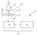
먼저, 도 1을 살펴보면, 초음파를 사용하여 물품(12)의 치수를 측정하는 장치(10)가 도시되어 있다.First, referring to FIG. 1, an
초음파는 사람의 청각을 뛰어넘는 음향 주파수 스펙트럼의 부분을 의미하고, 일반적으로 주파수가 20kHz 초과인 음향을 포함하는 것으로 간주한다. 초음파 펄스는 물질의 성질에 의해 결정되는 속도로 고체를 통해 통과한다. 초음파 펄스는 일반적으로 음향 성질의 변화가 일어날 때 계면 또는 경계로부터 반사된다.Ultrasound refers to a portion of the acoustic frequency spectrum that goes beyond human hearing and is generally considered to include sounds with frequencies above 20 kHz. Ultrasonic pulses pass through a solid at a rate determined by the nature of the material. Ultrasonic pulses are generally reflected from interfaces or boundaries when changes in acoustic properties occur.
경계로부터 반사되는 초음파 신호는 그 경계에 대한 정보를 포함한다. 예를 들어, 경계까지의 거리에 대한 정보는 물품 내로 진송된 초음파 펄스가 물품을 통과하여 경계에 이른 다음, 반사로서 되돌아오는데 걸리는 시간을 측정하여 결정할 수 있다. 이와 같이 측정된 시간으로부터 반사파가 이동한 거리를 계산하는 것이 가능하다(물품이 제조된 물질에서의 음향 속도를 알면). 이 거리는 물품의 치수, 특히 경계까지의 거리를 나타낸다. 경계가 표면인 경우, 치수는 물품의 두께를 나타낸다.The ultrasonic signal reflected from the boundary includes information about the boundary. For example, the information about the distance to the boundary may be determined by measuring the time it takes for the ultrasonic pulse transmitted into the article to pass through the article, reach the boundary, and then return as reflections. From this measured time it is possible to calculate the distance traveled by the reflected wave (knowing the speed of sound in the material from which the article was made). This distance represents the dimensions of the article, in particular the distance to the boundary. If the boundary is a surface, the dimension represents the thickness of the article.
이 방법은 도 2에 더욱 분명하게 예시했다. 도 2A는 물품(12)에 결합된 초음파 송수신기(18)를 보여준다. 송수신기(18)가 적당한 전기 펄스에 의해 여기되면, 송수신기는 초음파 신호 i를 방출한다. 이 신호는 물품을 통해 일반적으로 송수신기가 고정된 표면의 평면에 법선인 방향으로 전송된다. 신호가 경계, 예컨대 물품의 검사 표면(28)에 도달하면, 이 신호의 적어도 일부는 반사한다. 반사된 신호 r은 초음파 송수신기(18)에서 검출되고 전기 신호로 변환된다.This method is illustrated more clearly in FIG. 2A shows an
또한, 도 2A는 전송된 펄스 i와 반사된 펄스 r의 시간 경과에 따른 진폭 변동을 그래프(30)로 나타낸 것이다. 반사된 신호는 일반적으로 전송된 신호와 형태가 유사하나, 일부 신호 에너지가 상실(약화로 인해, 그리고 모든 신호가 반드시 반사되는 것은 아니기 때문에)되므로, 진폭은 감소했다.FIG. 2A also shows a graph 30 of amplitude variation over time of transmitted pulse i and reflected pulse r . The reflected signal is generally similar in shape to the transmitted signal, but because some signal energy is lost (due to weakening and not all signals are necessarily reflected), the amplitude is reduced.
전송된 펄스와 수신된 펄스 사이의 시간(31)은 신호의 '비행시간'이다. 이 비행시간(31)은 신호가 이동한 거리를 나타내고, 이 거리는 물품 두께의 2배와 같다.The
도 2B는 도 2A와 유사한 상황이지만, 도 2A에 도시된 물품(12)보다 얇은 물품(112)의 상황을 예시한 것이다. 이 예에서, 물품(112)은 약간의 마모를 겪은 후의 물품(12)이다. 도 2B에서 외향성 i와 반사된 r 펄스 사이의 시간(31)은 이동 거리가 짧기 때문에 도 2A의 해당 시간보다 적다는 것을 알 수 있을 것이다.FIG. 2B illustrates a situation similar to FIG. 2A, but with an
치수를 측정하는 것, 특히 마모를 표시하기 위해 실시간으로 치수 변화를 측정하는 것의 1가지 단점은 치수 측정이 반드시 어느 정도의 불확실성을 포함한다는 것이다.One disadvantage of measuring dimensions, in particular measuring dimension changes in real time to indicate wear, is that the dimension measurements necessarily include some uncertainty.
본원에 사용된, "불확실성"(U라고도 명명됨)이란 용어는 두께의 1회 측정값(X)이 X±U가 샘플의 실제 기본 평균 두께 값에 대해 95% 신뢰구간을 형성할 정도의 값이라는 것을 의미한다. s는 짧은 시간 기간 동안 일정 온도에서 안정 상태에 있는(마모가 일어나지 않음) 동일 샘플에서 반복적인 두께 측정값의 큰 샘플로부터 수득될 수 있는 표준 편차로 하자. 이 샘플링 절차는 측정값들이 자동상관성이 없는 정도라 가정한다. 그러면, 불확실성은 1.96·s로 정의된다.As used herein, the term “uncertainty” (also called U) is used so that one measurement of thickness (X) is such that X ± U forms a 95% confidence interval for the actual base average thickness value of the sample. Means. Let s be the standard deviation that can be obtained from large samples of repeated thickness measurements in the same sample that are stable at a constant temperature for a short period of time (no wear occurs). This sampling procedure assumes that the measurements are not autocorrelated. The uncertainty is then defined as 1.96 · s.
또한, 온도-조정된 두께 측정과 관련이 있는 불확실성은, 샘플링 절차가 온도가 무작위로 선택되고 측정이 독립적이도록 채택된다고 가정하여, 다른 온도에서 마모가 전혀 일어나지 않은 동일 샘플에 대한 측정값 사이의 표준 편차를 기반으로 하여 한정하는 것이 가능하다. 이 불확실성은 보정 방정식의 파라미터의 추정값에 불확실성이 있을 수 있기 때문에 일정 온도 시의 불확실성보다는 클 것이다.In addition, the uncertainty associated with temperature-adjusted thickness measurements is the norm between measurements for the same sample with no wear at different temperatures, assuming that the sampling procedure is chosen such that the temperature is chosen randomly and the measurements are independent. It is possible to define based on the deviation. This uncertainty will be greater than the uncertainty at constant temperature because there may be uncertainty in the estimates of the parameters of the calibration equation.
이 불확실성은 샘플 제조로 인한 또는 실험 간의 변화를 의도적으로 고려하지 않아서보다는, 오히려 측정 중의 단기간 변화로 인해 특정 시간에 특정 측정과 관련된 불확실성이 있기 때문에, 방법의 반복가능성과는 별개인 것이다.This uncertainty is separate from the repeatability of the method, as there is uncertainty associated with a particular measurement at a particular time due to short-term changes during the measurement, rather than intentionally not considering changes due to sample preparation or between experiments.
마모 측정의 불확실성은 마모가 일어나기 전과 일어난 후의 동일 샘플에서의 측정값 사이의 차이에 대해 95% 신뢰구간 폭의 ½로서 정의되고 1.96·s·√2와 같다. 사용된 s의 값은 적절하게 미처리(raw) 두께 측정값 또는 온도-조정된 두께 측정값을 기반으로 할 수 있다.The uncertainty of wear measurements is defined as ½ of the 95% confidence interval width for the difference between the measurements in the same sample before and after wear occurs and equals 1.96 · s · √2. The value of s used may be based on suitably raw thickness measurements or temperature-adjusted thickness measurements.
유용한 마모 표시를 제공하기 위해, 두께의 작은 변화(즉, 작은 마모량)가 검출될 수 있도록 치수를 매우 낮은 불확실성으로 측정할 수 있는 것이 필요하다. 일반적으로, 불확실성이 1㎛ 미만인 마모, 바람직하게는 10nm 이하인 마모를 검출할 수 있는 것이 바람직하다. 예를 들어, 1초의 시간 기간 동안 측정했을 때 1 내지 5nm 사이의 불확실성이 바람직할 수 있다.In order to provide a useful indication of wear, it is necessary to be able to measure the dimension with very low uncertainty so that small changes in thickness (ie small amount of wear) can be detected. In general, it is desirable to be able to detect wear with an uncertainty of less than 1 μm, preferably less than 10 nm. For example, uncertainty between 1 and 5 nm may be desirable when measured over a one second time period.
이러한 정확도로 거리를 측정하기 위해서는 초음파 펄스의 비행시간을 피코초(picosecond) 내로 측정할 것을 필요로 할 것이다. 이것은 현재 어렵고 비용이 많이 들며, 실험실외 환경에서 비실용적이다.Measuring distance with this accuracy would require measuring the flight time of the ultrasonic pulses in picoseconds. This is currently difficult, expensive and impractical in an out-of-lab environment.
본 발명자들은 비행시간의 매우 정확한 단독 측정으로부터 치수 측정값을 수득하기보다는 복수의 덜 정확한 비행시간 측정값들로부터 불확실성이 낮은 치수 측정값이 수득될 가능성이 있다는 것을 발견했다.The inventors have found that there is a possibility that dimensional measurements with low uncertainty are likely to be obtained from a plurality of less accurate flight time measurements, rather than obtaining dimension measurements from a very accurate single measurement of time of flight.
도 1에 도시된 장치 (10)은 특정 기간(예컨대, 1초) 동안 꼬리를 물고 비행시간의 다중 값을 측정하도록 작동할 수 있다. 이러한 다중 값은 통계학적으로 합하여 그 특정 기간 동안 물품의 치수 값을 측정하는데 사용되는 복합 비행시간 값을 수득한다.The
제시된 예에서, 검사되는 물품(12)은 제2 물품(14)과 접촉하고 있고 두 물품 사이의 상대적 움직임(도 1에서 화살표 16으로 표시됨)이 일어난다. 시간이 갈수록 물품 (12)와 (14) 사이의 상대적 움직임은 두 물품에 마모를 유발한다. 오일계 윤활제와 같은 윤활제는 마모 효과를 변경, 특히 줄이기 위해 물품 사이에 제공될 수 있다.In the example shown, the
장치(10)는 2가지 주요 부품, 즉 초음파 송수신기(18) 및 조절 시스템(20)을 포함한다. 초음파 송수신기는 압전 변환기의 형태로서, 검사 중인 물품(12)에 초음파 펄스를 전송하고 물품(12)으로부터의 초음파 펄스를 수신할 수 있다. 초음파 변환기는 예컨대 물품의 표면(22)에 변환기를 접착시키거나, 또는 물품에 압전 결정을 침착시켜 동일계에서 변환기를 형성시킴으로써, 물품(12)에 물리적으로 연결되어 있다.The
조절 시스템(20)은 초음파 변환기와 소통하고 있고, 초음파 변환기(18)가 초음파 신호를 방출하도록 작동할 수 있다. 조절 시스템(20)은 또한 변환기에 의해 검출된 초음파 신호를 해석하기 위해 작동할 수 있다.The
조절 시스템(20)은 펄스 생성 모듈(24)과 조절기 모듈(26)을 포함한다. 펄스 생성 모듈(24)은 조절기 모듈(26)로부터의 명령에 반응하여 초음파 변환기를 여기시키기 위해 전기 펄스를 발생하도록 작동할 수 있다. 전기 펄스에 의해 여기될 때, 초음파 변환기는 초음파 펄스를 방출하도록 유발된다.The
펄스 생성 모듈(24)은 초음파 변환기에 의해 발생된 전기 신호를 수신하도록 작동할 수 있다. 전기 신호는 초음파가 초음파 변환기에 입사할 때 생성된다. 펄스 생성 모듈은 수신된 전기 신호를 해석 및 분석용 조절기 모듈로 소통하도록 작동할 수 있다.The
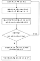
사용 시, 도 1에 도시된 장치는 도 7에 제시된 방법을 실행하여 검사 중인 물품(12)의 치수(11) 값을 측정한다.In use, the apparatus shown in FIG. 1 performs the method shown in FIG. 7 to measure the value of dimension 11 of the
단계(S1)에서 초음파 펄스는 검사 중인 물품(12)을 통해 전송된다. 특히, 조절기 모듈은 펄스 생성 모듈이 전압 펄스를 발생하게 하고, 결국 초음파 변환기가 초음파 펄스를 발생하도록 한다. 초음파 펄스는 초음파 변환기가 물품에 연결, 이 실시예에서는 영구적으로 연결되어 있기 때문에 물품 내로 전송된다.In step S1, the ultrasonic pulse is transmitted through the
전송된 초음파 펄스는 이어서 물품의 검사 표면(28)으로부터 반사되고 반사된 펄스는 단계 S2에서 수신된다. 반사된 펄스는 초기 펄스가 전송된 위치와 같은 위치에서 수신되고, 특히 펄스가 발생한 초음파 변환기에서 수신된다. 초음파 펄스는 초음파 송수신기에 의해 전기 신호로 변환되고, 해석을 위한 조절기 모듈로 전송된다. 수신된 초음파 펄스와 변환된 전기 신호는 모두 표면까지의 거리에 대한 정보를 함유한다.The transmitted ultrasonic pulses are then reflected from the
단계 S3에서 펄스의 비행시간은 전기 신호로부터 결정된다. 일반적으로, 단독 비행시간 값은 ±1㎛의 불확실성으로 측정될 수 있고, 이는 일반적으로 마모 정량 목적에는 너무 큰 불확실성 값이다. 장치(10)에서, 비행시간 값은 조절 시스템, 특히 조절기 모듈에 의해 측정되고 메모리에 저장된다.In step S3 the flight time of the pulse is determined from the electrical signal. In general, a single flight time value can be measured with an uncertainty of ± 1 μm, which is generally too large for uncertainty purposes of wear. In
단계 S4에서, 단계 S1 내지 S3은 충분한 수의 비행시간 값이 수집될 때까지 반복된다. 이 경우에 충분한 이란, 초음파 측정의 가변성에 기초하여 바람직한 불확실성으로 물품의 두께를 나타내는 충분한 데이터 점을 의미한다. 이 수는 보통 사전에 측정되지만, 반드시 그럴 필요는 없다. 반복 횟수는 1보다 큰 임의의 자연수(예컨대, 2, 10, 100, 1000, 10000, 1,000,000 등)일 수 있다. 일반적으로, 수집된 값의 수가 클수록 더 큰 정확성이 달성된다.In step S4, steps S1 to S3 are repeated until a sufficient number of flight time values have been collected. Sufficient in this case means sufficient data points representing the thickness of the article with the desired uncertainty based on the variability of the ultrasonic measurements. This number is usually measured in advance, but it is not necessary. The number of repetitions can be any natural number greater than one (eg, 2, 10, 100, 1000, 10000, 1,000,000, etc.). In general, the greater the number of values collected, the greater the accuracy achieved.
이 장치(10) 예에서, 조절 시스템은 단계 S1 내지 S3을 소정의 횟수만큼 반복하도록 작동할 수 있다. 조절 시스템은 메모리가 소정의 값과 수가 동일한 비행시간 값의 세트를 포함할 때까지 측정된 복수의 비행시간 값을 메모리에 저장한다.In this
소정의 수의 값들이 수집되었으면, 방법은 단계 S5로 이동한다. 단계 S5에서 복수의 측정된 비행시간 값은 합산해서 복합 비행시간 값을 수득한다. 제시된 방법 예에서, 값들의 정상 분포는 값들을 통계적으로 합산해서 평균값을 결정하는데 사용된다. 평균값으로부터의 표준 편차는 또한 평균값의 표준 오차를 계산하는데 사용될 수 있다. 복합 비행시간 값이 수득되었으면, 측정된 개별 비행시간 값은 필요하다면 폐기할 수 있다(예컨대, 메모리에서 삭제할 수 있다).If a predetermined number of values have been collected, the method moves to step S5. In step S5 the plurality of measured flight time values are summed to obtain a composite flight time value. In the example method presented, the normal distribution of values is used to statistically sum the values to determine the mean value. The standard deviation from the mean value can also be used to calculate the standard error of the mean value. Once the combined flight time values have been obtained, the individual flight time values measured can be discarded if necessary (eg, deleted from memory).
단계 S6에서 복합 비행시간 값은 복수의 측정이 일어난 기간 동안 각 초음파 펄스가 이동한 평균 거리를 나타내는 단독 치수 값을 수득하는데 사용된다. 선택된 시간 기간은 극도의 마모 조건에서도 물리적 거리가 크게 변화할 가능성이 없도록(예컨대, 1nm 미만) 충분히 짧은 것이다. 예를 들어, 복수의 측정은 동일한 초 내에 이루어질 수 있다.In step S6 the composite flight time value is used to obtain a single dimension value representing the average distance traveled by each ultrasonic pulse during a period of time during which a plurality of measurements have taken place. The chosen time period is short enough so that even in extreme wear conditions there is no possibility of a significant change in physical distance (eg less than 1 nm). For example, multiple measurements can be made within the same second.
이러한 방식의 많은 측정 결과를 합산하면 잡음(noise) 효과가 평균 단계에서 말소되기 때문에 검사 중인 치수의 불확실성 값이 더 작아지게 된다.Adding up the results of many measurements in this way results in a smaller uncertainty value for the dimension under test because the noise effect is erased at the average stage.
이러한 방법 및 시스템은 물품의 치수, 예컨대 두께를 실시간으로 측정하는데 사용할 수 있다. 본 발명자들은 3초 기간 동안 측정된 약 40,000회의 비행시간 값 세트를 사용하여 10nm 미만(일반적으로 1 내지 5nm 또는 2 내지 3nm)의 불확실성으로 치수를 측정하는 것이 가능하다는 것을 발견했다.Such methods and systems can be used to measure dimensions, such as thickness, of an article in real time. We have found that it is possible to measure dimensions with an uncertainty of less than 10 nm (typically 1 to 5 nm or 2 to 3 nm) using a set of about 40,000 flight time values measured over a 3 second period.
다중 치수 값은 도 7에 제시된 방법이 간격을 두고, 예컨대 0.2초마다 1회, 1초마다 1회, 1분마다 1회 또는 10분마다 1회와 같이 규칙적인 간격으로 반복한다면 수득될 수 있다. 복수의 치수 값은 조절기 모듈의 메모리에 저장될 수 있고(또는) 적당하다면 저장 및/또는 분석을 위해 원거리 위치로 전송될 수 있어, 마모율의 변화를 비롯한 시간 경과에 따른 마모율의 정확한 표시를 제공할 수 있다.Multiple dimension values can be obtained if the method presented in FIG. 7 is repeated at regular intervals, such as once every 0.2 seconds, once every second, once every minute or once every 10 minutes. . Multiple dimension values may be stored in the controller module's memory and / or transferred to a remote location for storage and / or analysis if appropriate, providing an accurate indication of wear rate over time, including changes in wear rate. Can be.
기술된 시스템과 방법은 견실하여, 실험실뿐만 아니라 현장에서도 사용될 수 있다. 이 시스템은 두께의 극한 변화를 측정할 수 있고, 얇은 방사능 표면층의 마모를 측정하는데 제한되지 않는다. 이 시스템은 초음파 펄스가 전송될 수 있는 임의의 물질, 예컨대 금속, 수지 및 플라스틱에 사용될 수 있다. 게다가, 하나의 시스템(10)에 임의의 수의 초음파 변환기가 제공될 수 있거나, 다중 시스템(10)이 나란히 사용될 수 있어 필요한 경우 복수의 여러 부품에서 다중 측정을 동시에 수행할 수 있게 한다.The systems and methods described are robust and can be used in the field as well as in the laboratory. This system can measure extreme changes in thickness and is not limited to measuring wear of thin radioactive surface layers. This system can be used for any material to which ultrasonic pulses can be transmitted, such as metals, resins and plastics. In addition, any number of ultrasonic transducers may be provided in one
실제 시스템에서 본원에 기술된 방법을 실행할 때, 본 발명자들은 다수의 요인이 측정 정확성에 영향을 미칠 수 있음을 발견했고, 이에 대해서는 이하에서 더 상세하게 논의한다.When carrying out the method described herein in a real system, the inventors have found that a number of factors can affect measurement accuracy, which is discussed in more detail below.
초음파 펄스 생성Ultrasonic Pulse Generation
전송된 초음파 펄스가 진폭이 너무 낮다면, 반사된 복귀 신호는 약화 손실 및 모든 신호가 반드시 반사되는 것은 아니라는 사실로 인해 배경 잡음에 우선하여 검출하는 것이 어려울 수 있다. 저 진폭 전송 펄스는 시스템이 습한 환경(예컨대, 검사 표면에 오일이나 다른 윤활제와 같은 액체가 존재하는 경우)에서 사용된다면 특히 문제가 있다.If the transmitted ultrasonic pulse is too low in amplitude, it may be difficult to detect the reflected return signal prior to background noise due to the attenuation loss and the fact that not all signals are necessarily reflected. Low amplitude transmission pulses are particularly problematic if the system is used in a humid environment (eg, where there is a liquid such as oil or other lubricant on the test surface).
일반적으로, 외향성 신호가 강할수록 이에 대응하는 반사 신호도 강하다. 하지만, 본 발명자들은 고 진폭 외향 펄스의 방출이, 특히 반사된 신호가 전술한 시스템 예에서와 같이 초기 펄스를 방출했던 동일 변환기에 의해 검출되는 경우에, 항상 최상의 결과를 제공하는 것은 아니라는 것을 발견했다.In general, the stronger the outward signal, the stronger the corresponding reflected signal. However, the inventors have found that the emission of high amplitude outward pulses does not always provide the best results, especially when the reflected signal is detected by the same transducer that emitted the initial pulse as in the system example described above. .
전압 펄스의 방출 후, 펄스 생성기는 일반적으로 '휴식' 기간을 경험하고 그 동안 유의적인 잡음이 생긴다. 방출되는 전압 펄스가 높을수록 이 잡음 양도 많아지고 소멸하는데 걸리는 시간도 길어진다. 이 휴식 기간이 너무 크면, 신호가 잡음에서 사라질 가능성이 있기 때문에 복귀하는 초음파 펄스의 검출이 곤란할 수 있다.After the release of the voltage pulse, the pulse generator typically experiences a 'rest' period, during which significant noise occurs. The higher the voltage pulse emitted, the greater this amount of noise and the longer it takes to dissipate. If this rest period is too large, detection of the returning ultrasonic pulse may be difficult because the signal may disappear from the noise.
따라서, 이러한 정반대의 이유를 고려하여 펄스 생성 모듈의 여기 전압을 선택했다. 본 발명자들은 적당한 전압이 200V 미만, 예컨대 1 내지 100V 범위, 특히 3 내지 20V 범위 내인 것을 발견했다. 이하에 기술된 샘플 시스템은 10V 전압을 사용한다.Therefore, the excitation voltage of the pulse generation module was selected in consideration of these exact opposite reasons. We have found that a suitable voltage is less than 200V, such as in the range of 1 to 100V, in particular in the range of 3 to 20V. The sample system described below uses a 10V voltage.
또한, 본 발명자들은 생성된 전압 펄스(이에 따른 초음파 펄스)가 반복가능한 형상일 때 양호한 결과가 달성된다는 것을 발견했다. 반복가능한 펄스 형상의 사용은 반복적인 비행시간 측정을 간단하게 하고, 복합 비행시간 값에 미치는 잡음의 영향을 감소시키기도 한다. 또한, 펄스 생성이 반복가능하다면(또는 생성 시의 적어도 임의의 변화가 예측가능하고 최소화된다면) 시스템은 온도에 대하여 더욱 쉽게 보정될 수 있다(이하에 더 상세히 설명됨).In addition, the inventors have found that good results are achieved when the resulting voltage pulses (and thus ultrasonic pulses) are repeatable in shape. The use of repeatable pulse shapes simplifies repetitive flight time measurements and also reduces the effects of noise on complex flight time values. Also, if the pulse generation is repeatable (or at least any change in generation is predictable and minimized), the system can be more easily corrected for temperature (described in more detail below).
압전 초음파 변환기는 이 변환기에 전압 펄스를 공급하여 여기시킬 수 있다. 이러한 전압 펄스를 발생시키는 1가지 방법은 커패시터(capacitor)의 사용이다. 다른 방법은 연산증폭기이다. 이 두 방법은 모두 적당히 반복가능한 펄스를 생산한다. 하지만, 증폭기에 의해 생성된 신호의 형상은 일반적으로 특정 파형을 생성시키는 커패시터에 의해 생성된 신호보다 더욱 조절가능하다. 특히, 증폭기를 사용하면 사인파의 생성이 가능해진다(예컨대, 정사각형파, 삼각형파 또는 사인파로 형상화된 전압 펄스를 생산하여)Piezoelectric ultrasonic transducers can be excited by supplying a voltage pulse to the transducer. One way of generating such a voltage pulse is through the use of a capacitor. Another method is an operational amplifier. Both of these methods produce pulses that are reasonably repeatable. However, the shape of the signal generated by the amplifier is generally more adjustable than the signal generated by the capacitor producing the particular waveform. In particular, the use of amplifiers enables the generation of sine waves (eg by producing voltage pulses shaped as square waves, triangle waves, or sinusoids).
초음파 변환기는 일반적으로 특정 주파수에서 가장 효과적으로 작용하도록 최적화되어, 이 주파수 작동에서 또는 그 부근에서 사인파 형태의 여기 펄스를 생성하는 것이 더욱 효과적일 수 있다.Ultrasonic transducers are generally optimized to work most effectively at specific frequencies, so it may be more effective to generate excitation pulses in the form of sinusoids at or near this frequency operation.
초음파 펄스 생성의 3번째 고려할 사항은 초음파 송수신기의 주파수(및 이에 따라 초음파 펄스의 주파수)에 관한 것이다. 일반적으로, 저 주파수 신호는 더 양호한 전송 특성(예, 약화 감소)을 나타낸다. 하지만, 본 발명자들은 고주파 신호가 반복가능한 방식으로 분석하기에 더 쉽다는 것을 발견했다(이하에 더 상세하게 논의됨). 적당한 주파수는 1 내지 100MHz 범위, 특히 3 내지 50MHz 범위에서 선택될 수 있다. 전술한 시스템은 10MHz의 주파수를 이용하지만, 30MHz 이하의 주파수, 예컨대 20MHz의 주파수도 양호한 결과를 제공하는 것으로 발견되었다.A third consideration of ultrasonic pulse generation relates to the frequency of the ultrasonic transceiver (and thus the frequency of the ultrasonic pulse). In general, low frequency signals exhibit better transmission characteristics (eg, reduced attenuation). However, the inventors have found that high frequency signals are easier to analyze in a repeatable manner (discussed in more detail below). Suitable frequencies can be chosen in the range from 1 to 100 MHz, in particular in the range from 3 to 50 MHz. While the above system uses a frequency of 10 MHz, it has been found that frequencies below 30 MHz, such as frequencies of 20 MHz, provide good results.
비행시간 측정Flight time measurement
반사된 펄스의 비행시간은 반사된 파의 소정의 특징이 수신되는 시간을 표시하여 측정할 수 있다. 이러한 수신된 시간은 외향성 펄스에서 등가의 특징이 생성된(측정되거나 또는 공지된 것일 수 있음) 시간과 비교하여 비행시간을 측정할 수 있다.The flight time of the reflected pulse can be measured by indicating the time at which the predetermined characteristic of the reflected wave is received. This received time can measure the time of flight compared to the time at which an equivalent characteristic is generated (which may be measured or known) in the outward pulse.
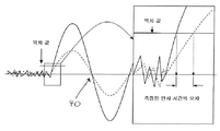
무엇을 기반으로 하든지 특징을 선택하면, 측정은 다수의 실제 고려사항을 필요로 한다. 일반적으로, 비행시간은 전송된 신호의 피크 진폭과 복귀 신호의 피크 진폭 사이의 시간을 측정하여 계산한다. 하지만, 검사 표면과의 상호작용은 반사된 신호의 형상을 왜곡시킬 수 있어, 모의 반사 피크와 비교 시, 측정된 반사 신호의 피크는 예상 위치로부터 이동할 수 있다. 이 현상은 도 3에 도시했고, 여기서, 모의 또는 '이상적' 반사의 경시적인 진폭 변화는 34에서 파선으로 표시되고 이에 중첩되어 실선의 측정된 반사가 비교되어 있다. 측정된 반사의 형상은 잡음으로 인해 이상적 신호에 대해 왜곡되어 있는 것을 볼 수 있을 것이다. 특히, x축에서 측정했을 때 그 피크가 나타나는 시간이 되었을 때 피크 진폭은 변했다.Whatever the basis, choosing a feature, the measurement requires a number of practical considerations. In general, the flight time is calculated by measuring the time between the peak amplitude of the transmitted signal and the peak amplitude of the return signal. However, the interaction with the test surface can distort the shape of the reflected signal, so that the peak of the measured reflected signal can shift from the expected position when compared to the simulated reflection peak. This phenomenon is illustrated in FIG. 3, where the change in amplitude over time of the simulated or 'ideal' reflections is indicated by dashed lines at 34 and overlaid to compare the measured reflections of the solid lines. It can be seen that the shape of the measured reflection is distorted for the ideal signal due to noise. In particular, the peak amplitude changed when the peak time appeared when measured on the x-axis.
반사된 피크의 형상 왜곡은 한번의 측정과 그 다음의 측정에서 반드시 일치하지는 않는다(예컨대, 표면 오염물은 경시적으로 분산하거나 증가할 수 있다). 피크간(peak to peak)을 측정할 때, 이러한 진폭 변동은 치수의 물리적 변화에 대응하지 않는 비행시간의 인지된 변화를 도입시켜 부정확성을 초래할 수 있다.The shape distortion of the reflected peak does not necessarily coincide with one measurement and the next (eg, surface contaminants may disperse or increase over time). When measuring peak to peak, such amplitude variations can introduce inaccurate changes in flight time that do not correspond to physical changes in dimensions.
본 발명자들은 제로 진폭의 두 점 사이의 시간을 비교하는 것이 더 나은 접근법이라는 것을 발견했다. 하지만, 이 접근법 역시 도 3 및 4에 예시한 바와 같이 문제가 있다.We have found that comparing the time between two points of zero amplitude is a better approach. However, this approach is also problematic as illustrated in FIGS. 3 and 4.
논리적 접근법은 반사파의 선두 가장자리를 조사하려는 것일 수 있다. 초기 펄스 생성에 커패시터 뱅크가 사용되었다면, 펄스 방출 후 제로 진폭에 도달하는데 지연이 있는 것이 일반적이고 이것은 최초 반사에 영향을 미칠 수 있다. 이러한 효과는 반사가 일어난 시간(37)(즉, 전송된 펄스의 출발 시간(35)에 동등한 시간)의 분석을 어렵게 한다. 도 3은 이상적인(잡음 없이) 반사의 출발 시간(37)이 어떻게 모호해질 수 있는지를 (36)에서 상세하게 예시하고 있다. 비행시간이 겉보기 '제로'(38)로 측정되었다면, 시간 이동 오차가 도입된다. 연산 증폭기 시스템이 사용되고 제로 진폭에 도달하는데 지연이 없다면, 선두 가장자리 역치 값이 촉발되었을 때를 측정하는데 있어서 여전히 문제가 있다. 이것은 도 4에 도시했고, 여기서 신호의 배경 잡음은 선두 가장자리가 상승하는 제로 진폭 점의 동정을 어렵게 한다.The logical approach may be to examine the leading edge of the reflected wave. If a capacitor bank is used for initial pulse generation, there is usually a delay in reaching zero amplitude after pulse emission, which can affect the initial reflection. This effect makes it difficult to analyze the
두 펄스의 초기(original) 시간 사이를 측정하는데 있어서의 다른 어려움은 데이터 분석에서 파를 동정할 때, 일반적으로 실제 제로점 자체보다 역치값이 조사된다는 것이다. 반사 진폭은 파(wave)에서 파로 변할 수 있기 때문에, 이 방법은 도 4에 예시된 바와 같이 추가 오차를 도입시킬 수 있다. 특히, 피크 진폭이 더 낮은 반사(파선으로 표시)가 역치값에 도달하는데 걸리는 시간은 피크 진폭이 높은 다른 반사(실선으로 표시)보다 더 길어서, 실제 아무것도 존재하지 않는 두 파 사이에 비행시간의 명백한 차이를 도입시킨다.Another difficulty in measuring between the original times of the two pulses is that when identifying the wave in the data analysis, the threshold value is typically examined rather than the actual zero point itself. Since the reflection amplitude can vary from wave to wave, this method can introduce additional errors as illustrated in FIG. 4. In particular, the time it takes for the reflection with lower peak amplitude (indicated by the broken line) to reach the threshold is longer than the other reflection with high peak amplitude (indicated by the solid line), so that the apparent time of flight between two waves where nothing is actually present. Introduce the difference.
반사된 파의 선두 가장자리를 모호하게 할 수 있는 잡음으로 인해, 대신 비행시간은 절편 제로(40)로 측정한다. 절편 제로(40)는 파가 진폭 축과 재교차하는 점이다(즉, 펄스의 출발 시간 후 제로 진폭이되 일정 시간이 있는 점). 본원에 기술된 시스템에 사용된 절편 제로(40)는 1차 절편 제로이거나, 또는 "2차 제로"이지만, 이후의 절편 점들도 바람직한 경우 사용될 수 있다.Due to the noise which may obscure the leading edge of the reflected wave, the flight time is instead measured with intercept zero 40. The intercept zero 40 is the point at which the wave reintersects the amplitude axis (ie, the point is zero amplitude after the start time of the pulse but there is a certain time). The intercept zero 40 used in the system described herein is the primary intercept zero, or "secondary zero," but subsequent intercept points may also be used if desired.
이러한 절편점에서 파는 본질적으로 선형이어서, 이 점의 위치는 다른 잡음으로부터의 최소의 방해 하에 축과 교차하기 전과 후에 수득한 측정값으로부터 반복해서 보간(interpolation)할 수 있다. 이 점은 도 3 및 도 4에 도시된 바와 같이 파의 진폭 변화에 의해 본질적으로 영향을 받지 않는다. 또한, 이 점에서는 다시 오차를 추가할 수 있는 다른 주파수로부터의 신호 내의 "숄더(shoulder)"가 존재하지 않는다.The wave at this intercept point is essentially linear so that its position can be repeatedly interpolated from measurements taken before and after crossing the axis with minimal interference from other noise. This point is essentially unaffected by the amplitude change of the wave as shown in FIGS. 3 and 4. Also at this point there is no "shoulder" in the signal from another frequency which can add errors again.
제로 진폭 축의 어느 면에서든지 실제 측정된 값 사이의 선형 보간을 고려하면, 신호의 주파수가 커질수록 선의 구배가 더 가팔라지고 측정 오차는 더 작아진다. 하지만, 앞서 논한 바와 같이, 신호를 위해 선택한 주파수는 시스템의 다른 요건들, 특히 신호가 전송되어야 하는 물질의 깊이와 균형을 맞출 필요가 있다.Considering linear interpolation between the actual measured values on either side of the zero amplitude axis, the higher the frequency of the signal, the steeper the gradient of the line and the smaller the measurement error. However, as discussed above, the frequency chosen for the signal needs to be balanced against other requirements of the system, in particular the depth of the material to which the signal is to be transmitted.
또한, 더 고주파가 사용되는 경우에는 데이터 샘플링 속도를 증가시킬 필요가 있다. 도 8은 주파수는 다르지만 동일한 속도로 샘플링되는 2개의 초음파를 예시한다. 이 도면에서 점선은 고주파 신호를 나타내고, 실선은 저주파 신호를 나타낸다. 제로 축에 절편을 보간할 때, 고주파 선의 구배가 더 가파를지라도 구배를 나타내는 데이터는 더 적다. 이 예에서, 실선은 100MHz에서 샘플링된 10MHz 신호를 나타내고, 점선은 100MHz에서 샘플링된 20MHz 신호를 나타낸다.In addition, when higher frequencies are used, it is necessary to increase the data sampling rate. 8 illustrates two ultrasounds that are sampled at the same rate but at different frequencies. In this figure, the dotted line represents the high frequency signal and the solid line represents the low frequency signal. When interpolating the intercept on the zero axis, there is less data indicating the gradient, although the slope of the high frequency line is steeper. In this example, the solid line represents a 10 MHz signal sampled at 100 MHz and the dashed line represents a 20 MHz signal sampled at 100 MHz.
신호가 검사 표면으로부터 반사될 때, 이 신호의 일부는 초음파 변환기가 연결된 표면으로부터 검사 표면쪽으로 재반사된다. 재반사된 신호의 일부는 그 다음 2차 반사로서 다시 반사된다. 이론적으로, 이러한 2차 반사(또는 더 고차 반사, 예컨대 3차, 5차 또는 심지어 20차 반사)의 비행시간의 측정은 이러한 반사에 의해 이동한 거리가 커짐으로써 더욱 정확한 결과를 생성할 것이다.When the signal is reflected from the test surface, part of the signal is reflected back from the surface to which the ultrasound transducer is connected to the test surface. Part of the rereflected signal is then reflected back as a secondary reflection. In theory, the measurement of the flight time of these secondary reflections (or higher order reflections, such as 3rd, 5th or even 20th order reflections) will produce more accurate results as the distance traveled by these reflections increases.
하지만, 반사 차수의 선택은 다시 반사된 신호의 질 및 배경 잡음으로부터 신뢰성있게 구별되는 능력에 대하여 균형을 맞추어야 한다. 실험을 통해 본 발명자들은 고차 반사를 사용하는 편이 나을 것으로 생각할 수 있지만, 최상의 측정은 초음파가 생성된 시간과 1차 반사 사이에서 이루어진 것으로 나타난다는 것을 알아냈다.However, the choice of reflection order should again be balanced against the quality of the reflected signal and the ability to reliably distinguish from background noise. Experiments have shown that the inventors may prefer to use higher order reflections, but found that the best measurements appear to have been made between the time when the ultrasound was generated and the first order reflections.
통계 분석Statistical analysis
앞서 논한 바와 같이, 비행시간 측정의 정확성에 영향을 미칠 수 있는 배경 잡음을 비롯하여 다양한 근원에서 유래되는 일련의 오차가 있다. 이러한 오차를 줄이기 위한 몇몇 방식은 앞에서 논했지만, 그럼에도 불구하고 각각의 개별 측정은 초단기 기간의 측정 곤란성으로 인해 정확성이 제한적이다.As discussed earlier, there are a series of errors from various sources, including background noise that can affect the accuracy of flight time measurements. Some ways to reduce this error have been discussed above, but each individual measurement nevertheless has limited accuracy due to the difficulty of measuring in the short term.
불확실성이 적은 비행시간 값을 수득하기 위해서는 일련의 측정값('샘플')을 합산하고 여기에 통계 작업을 수행하여 물질의 두께에 대한 복합 값을 알아낸다. 합산되는 샘플이 많을수록 최종 복합값의 불확실성은 적어진다. 취할 수 있는 샘플의 수는 물리적으로 제한적인데, 그 이유는 2차 신호를 전송하기 전에 1차 반사된 신호가 수신될 때까지(아마도 추가 반사가 소멸될 때까지) 기다릴 필요가 있기 때문이다.To obtain a low uncertainty flight time value, a series of measurements ('samples') are summed and statistical operations are performed on them to find a composite value for the thickness of the material. The more samples added, the less uncertain the final composite value. The number of samples that can be taken is physically limited because it is necessary to wait until the primary reflected signal is received (possibly until further reflections disappear) before transmitting the secondary signal.
적당한 샘플 세트는 1초 기간 동안 일정 간격으로 취한 샘플 10,000 내지 80,000개 사이를 포함할 수 있다. 이하에 기술되는 시스템 예는 3초마다 약 40,000개 샘플의 샘플 세트를 수집하도록 작동할 수 있다.Suitable sample sets may include between 10,000 and 80,000 samples taken at regular intervals over a one second period. The system example described below may operate to collect a sample set of about 40,000 samples every three seconds.
이러한 크기의 샘플 세트로부터 평균값(중간값 또는 최빈값(mode)과 대조적으로)의 계산은 계산 집약적이다. 특히, 본 발명자들은 계산 속도 면에서, 단일 큰 데이터 세트에 대한 통계보다는 더 많은 작은 데이터 세트를 수득한 뒤 이 세트에 통계를 수행하는 것이 더 낫다는 것을 발견했다. 그 이유는 큰 데이터 세트의 처리는 일반적으로 데이터를 쓰고 데이터를 판독하는 것을 필요로 하고 이것이 계산 공정을 지연시키는 반면, 작은 데이터 세트는 실시간으로 처리될 수 있기 때문이다. 이 시스템의 한 변형에 따르면, 복수의 수신된 신호에서 유래된 정보를 포함하는 세트는 복수(특히 10개)의 작은 서브세트로 나뉜다. 각 서브세트는 평균을 구해 비행시간 '부분값'을 수득하고, 그 결과 수득되는 부분값은 다시 합산하여 복합 값을 수득한다. 이러한 2단계 통계 분석은 단순히 개별적으로 측정된 비행시간 값의 전체 세트의 평균을 구하는 것보다 더욱 빠르고 효율적으로 계산할 수 있다. 또한, 본 발명자들은 1초 동안 지속적인 샘플링이 1초 기간이 넘게 다중 샘플 세트를 취할 때(예컨대, 0.2초마다 한 샘플 세트 수득)만큼 정확하지 않다는 것을 발견했다. 이것은 온도 변화의 효과가 더 짧은 시간 동안 더 작아질 가능성이 있기 때문이다.The calculation of the mean value (as opposed to the median or mode) from a sample set of this size is computationally intensive. In particular, the inventors have found that, in terms of computation speed, it is better to obtain more small data sets and then perform statistics on these sets than statistics for a single large data set. The reason is that processing of large data sets generally requires writing data and reading data, which delays the computational process, while small data sets can be processed in real time. According to one variant of this system, a set comprising information derived from a plurality of received signals is divided into a plurality (especially ten) of a small subset. Each subset is averaged to obtain the flight time 'partial value', and the resultant partial values are summed again to obtain a composite value. This two-step statistical analysis is faster and more efficient than simply averaging the entire set of individually measured flight time values. In addition, the inventors have found that continuous sampling for one second is not as accurate as taking multiple sample sets over a one second period (eg, obtaining one sample set every 0.2 seconds). This is because the effect of temperature change is likely to be smaller for a shorter time.
각각의 서브세트는 샘플 크기가 2 내지 100,000회의 비행시간 값, 예컨대 2 내지 45,000회, 100 내지 10,000회 또는 3000 내지 5000회 범위인 샘플 크기를 포함할 수 있다. 이하에 기술되는 시스템 예에서, 각 서브세트에서는 4005회 샘플이 채취된다. 이러한 수는 0.2s 내에 채취된 별도의 샘플의 수로서 선택되었다. 이론적으로, 더 작은 서브세트의 수가 많을수록 복합 값이 더욱 빠르게 측정될 수 있게 할 것이다. 하지만, 0.2s 보다 짧은 시간 기간에 걸친 서브세트를 온도에 동시에 연결하기는 어렵다.Each subset may include a sample size ranging from 2 to 100,000 flight time values, such as from 2 to 45,000, 100 to 10,000, or 3000 to 5000 times. In the example system described below, 4005 samples are taken in each subset. This number was chosen as the number of separate samples taken within 0.2 s. In theory, the larger the number of smaller subsets, the faster the composite value can be measured. However, it is difficult to simultaneously connect the subsets over temperature with a time period shorter than 0.2 s.
따라서, 한 시스템 예에 따르면, 4005회의 10개의 서브세트가 연속 10회의 0.2s 기간(0.1초 이격될 수 있다) 동안 수득된다. 비행시간 부분값은 각 서브세트마다 수득된다. 이러한 10회의 부분값은 그 다음 합산하여 3초 기간 동안의 비행시간 값을 생성한다. 이 복합 비행시간 값은 약 40,000회의 개별 측정값으로부터의 데이터를 포함한다.Thus, according to one system example, 10 subsets of 4005 times are obtained for 10 consecutive 0.2s periods (which can be 0.1 seconds apart). The flight time part value is acquired for each subset. These ten partial values are then summed to produce a flight time value for a three second period. This composite flight time value includes data from approximately 40,000 individual measurements.
각 서브세트의 평균값을 계산하기 위한 대안적 접근법은 더욱 정확한 단일 파를 생성하기 위해 샘플의 서브세트를 인터리브하는 것일 수 있다(예컨대, 최고 20개의 연속 샘플이 인터리브될 수 있다). 이와 같이 인터리브된 파는 앞서 논한 바와 같이 통계적으로 합산되어 복합 값을 생성할 수 있다.An alternative approach to calculating the average value of each subset may be to interleave a subset of samples to produce a more accurate single wave (eg, up to 20 consecutive samples may be interleaved). Such interleaved waves can be statistically summed to generate a composite value as discussed above.
온도 보상Temperature compensation
온도 변화는 여러 측정 성질을 변화시킨다. 이러한 성질로는 무엇보다도 다음을 포함한다:Temperature changes change several measurement properties. These properties include, among other things, the following:
· 물질의 팽창/수축이 측정되어 기록되는 겉보기 두께의 변화· Change in apparent thickness at which the expansion / contraction of the material is measured and recorded
· 초음파 변환기의 반응 특징들의 변화Changes in the response characteristics of the ultrasonic transducer
· 접착선의 팽창/수축Expansion / Shrinkage of Adhesive Line
· 접착제와 측정된 물질을 통과하는 음향 속도에 대한 변화.The change in sound velocity through the adhesive and the measured material.
· 물질을 통과하는 음향 속도의 변화.Changes in the speed of sound through the material.
상기 효과들은 반복적이고 대부분 온도에 1차적이다. 따라서, 치수값을 수득할 때 온도 변화에 대해 보상하는 것이 가능하다. 이것은 마모가 일어나지 않고 온도가 변동되는 경우 실험 보정(calibration)에 기초한 1차 교정(correction)을 사용하여 수행할 수 있다. 마모는 아니지만 온도 변화를 겪은 표본을 측정하면 온도와 두께를 관련 짓는 것이 가능하다.The effects are repetitive and mostly primary to temperature. Thus, it is possible to compensate for temperature changes when obtaining dimension values. This can be done using first-order correction based on experimental calibration when no wear occurs and the temperature fluctuates. It is possible to correlate temperature and thickness by measuring specimens that have undergone temperature changes, but not wear.
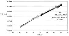
도 5는 이러한 보정의 결과를 도시한 것이다. 제시된 그래프에서, 데이터 점은 표본이 마모 처리됨이 없이 가열 및 냉각되는 실험 동안 수집했다. 각 데이터 점은 0.2초 안에 포착된 두께의 4005회 측정 결과이다. 시스템은 분당 100회 수집물로 운영했고, 두께는 온도에 대하여 플로팅했다. 이 점으로부터 선형 관계가 추정되고 적당한 '직선(straight-line)' 기능이 계산되었다(스플라인 기능, 색인 표 또는 다항식과 같은 다른 옵션이 유용하지만). 이 관계는 그 다음 후속 판독값(예, 마모 시험 동안)을 초기 값에 동일시하는데 사용된다. 예를 들어, 측정된 두께는 표준 온도에 대하여 다시 보정할 수 있다.5 shows the result of this correction. In the graph presented, data points were collected during the experiment where the specimen was heated and cooled without abrasion. Each data point is 4005 measurements of thickness captured in 0.2 seconds. The system was run with 100 collections per minute and the thickness plotted against temperature. From this point a linear relationship was estimated and a suitable 'straight-line' function was calculated (although other options such as spline functions, index tables or polynomials were useful). This relationship is then used to identify subsequent readings (eg, during the wear test) to initial values. For example, the measured thickness can be corrected again for the standard temperature.
온도 변동은 측정된 두께 값을 유의적으로 변경시킬 수 있다. 따라서, 초음파 두께 측정값과 거의 동시에 정확한 온도 측정값을 획득하여 치수 값이 보정되도록 하는 것이 바람직할 수 있다. 정확하고 반복가능한 온도 판독값을 수득하는 1가지 방식은 초음파 센서 옆에 검사 물품의 표면에 장착된 열전대를 사용하는 것이다. 또한, 물품의 다른 깊이에서 또는 물품과 떨어진 표면(예컨대, 마모를 겪는 표면)과 같이 다른 위치에서의 추가 온도 판독값을 제공하는 것이 유용할 수도 있다.Temperature fluctuations can significantly change the measured thickness values. Therefore, it may be desirable to obtain an accurate temperature measurement almost simultaneously with the ultrasonic thickness measurement so that the dimensional value is corrected. One way to obtain accurate and repeatable temperature readings is to use a thermocouple mounted on the surface of the test article next to the ultrasonic sensor. It may also be useful to provide additional temperature readings at other depths of the article or at other locations, such as surfaces away from the article (eg, surfaces that are subject to wear).
실제 시스템Real system
상기 고려할 사항을 감안하는 초음파 치수 측정 시스템(100)은 도 6에 개략적으로 도시했다. 이 시스템(100)은 장치(10)와 공통된 다수의 특징을 공유한다. 특히, 시스템(100)은 초음파 송수신기(118), 및 펄스 생성 모듈(124)과 조절기 모듈(126)을 포함하는 조절 시스템(120)을 포함한다.Ultrasonic
초음파 변환기(118)는 접착제와 같이 고정제를 사용하여 검사 중인 물품(도시되지 않음)에 사용 시에 고정된 압전 변환기를 포함한다. 필요하다면, 초음파 변환기는 물품의 표면에 동일계에서 침착되기도 한다. 선택된 고정제는 주로 물품 및 사용 시 경험할 것으로 예상되는 조건에 따라 달라지지만, 사용 시 예상되는 온도 범위에 걸쳐서 초음파 신호의 양호한 전송을 가능하게 할 필요가 있다. 제 위치에 고정 시 센서는 물품에 초음파 신호를 전송하는데 도움을 주기 위해 백킹, 예컨대 에폭시 수지 백킹, 예를 들어 강철 보강 에폭시로 피복될 수 있다. 변환기(118)는 약 10MHz의 주파수를 갖지만, 앞서 논한 바와 같이 다른 주파수도 가능하다.
펄스 생성 모듈(124)은 약 10V의 피크 진폭을 가진 전압 펄스를 생성하도록 작동할 수 있다. 펄스 생성 모듈은 펄스 생성기(140), 증폭기(142) 및 신호 차단기(144)를 포함한다. 펄스 생성기는 반복성 형태를 가진 실질적으로 1V의 전압 펄스를 생성하도록 작동할 수 있다. 이 예에서, 펄스는 실질적으로 10MHz의 주파수를 가진 사인파를 포함하고, 펄스 생성기(140)는 필드 프로그램가능 게이트 어레이(FPGA1)와 같은 1차 프로그램가능 요소를 포함한다. 전송될 초기 펄스의 생성뿐만 아니라 FPGA1은 반사된 신호를 수신하도록 작동할 수 있다.The
증폭기(142)는 FPGA1에 의해 생성된 형상화된 신호를 주파수 변경 없이 약 10V 펄스로 증폭시키도록 작동할 수 있다. 이러한 고전압 신호가 FPGA1에 의해 수신되면, 이것은 FPGA1을 손상시킬 수 있다. 따라서, 증폭기가 활성화되면, 이 예에서 전계효과 트랜지스터(FET)인 신호 차단기(144)는 동시에 활성화되어, 10V 신호의 어떠한 부분도 FPGA1쪽으로 다시 전송될 수 없도록 할 수 있다. 증폭기가 10V 펄스를 전송하자마자, 신호 차단기(144)는 불활성화되어 반사된 신호가 FPGA1에 의해 검출될 수 있게 한다.
조절기 모듈(126)은 제2 필드 프로그램가능 게이트 어레이(FPGA2)와 같은 추가 프로그램가능 요소(146), 프로세서(148) 및 메모리(149)를 포함한다. FPGA2는 검사 중인 물품의 온도를 측정하기 위해 배열된 열전대와 같은 온도 센서(150)로부터 온도 데이터를 수집하도록 작동할 수 있다.The regulator module 126 includes additional
프로세서(148)는 프로그램가능한 요소(140) 및 (146) 모두와 신호 통신되고, FPGA1로부터의 신호 데이터와 FPGA2로부터의 온도 데이터를 수신한다. 프로세서는 수신된 신호 데이터 및 온도 데이터를 사용하여 치수 측정값을 생성한다.
작동 시, 시스템(100)은 다음과 같은 2 세트의 작동을 프로세서의 조절 하에 실질적으로 동시에 수행한다.In operation,
첫째, 프로그램가능 요소(140)는 1V 펄스를 50ns 기간 동안 생성한다. 신호 차단기(144)가 활성화되고 증폭기(142)가 1V 펄스를 10V로 증폭시킨다. 그 다음 신호 차단기는 불활성화된다. 10V 신호는 케이블을 통해 초음파 송수신기(118)로 전송된다. 초음파 송수신기는 신호를 초음파 펄스로 변환시키고 검사 중인 물품 내로 펄스를 전송한다. 반사된 초음파 펄스는 이어서 초음파 송수신기에 의해 수신되어 전기 시그널로 변환되고 프로그램가능 요소(140)에 의해 검출된다. 수신된 신호(및 특히 수신된 신호의 형상을 함께 나타내는 별도의 측정값들의 수집물)를 동정하는 데이터는 분석/저장을 위해, 특히 비행시간 값을 수득하기 위해 프로세서로 전송한다. 이러한 세트의 작업은 특정 시간 기간 동안 소정의 횟수로 반복하고, 이 예에서는 0.2s 내에 약 4005회 반복된다.First,
초음파 송수신기(118)는 별도로 구현된 초음파 전송기 및 초음파 수신기로 교체될 수 있다. 이것은 신호 차단기(144)를 불필요하게 하도록, 전송기에 의해 제공된 여기로부터 수신기를 분리하는데 도움을 줄 것이다. 이는 도 6에서 송수신기(118)에 파선으로 표시하여 전송기와 별개의 수신기의 사용을 나타낸다.The
상기 비행시간 데이터의 수집과 동시에, 프로세서는 제2 프로그램가능 요소(146)에 명령하여 온도 센서(150)로부터 온도 데이터를 수집한다. 측정된 온도 값(2회 측정으로 구성됨)은 FPGA1이 소정의 샘플 수를 수집할 때까지 메모리에 저장한다. 이러한 작업은 실질적으로 동시에 개시 및 종료하도록 배열된다. Concurrent with the collection of the time of flight data, the processor instructs the second
일단 소정의 측정 수에 대한 신호 데이터가 수집되면, 프로세서는 앞서 논한 바와 같이 1차 절편 제로의 위치를 정하여 각 측정값들에 대한 비행시간을 결정한다. 이러한 비행시간 값의 세트는 그 다음 평균을 구하여 단일 비행시간 값으로 만든 뒤, 온도 값을 사용하여 보정한다. 그 다음, 온도 독립적 치수 값을 계산한다. 이 값은 측정 작업이 일어난 0.2s 동안에 검사 중인 물품의 두께를 나타낸다.Once the signal data for a given number of measurements is collected, the processor determines the time of flight for each measurement by positioning the first intercept zero as discussed above. This set of time values is then averaged to a single time value, and then corrected using temperature values. The temperature independent dimension value is then calculated. This value represents the thickness of the article under test for 0.2 s during which the measurement operation took place.
이 시스템은 상기 작업들을 소정의 횟수로 반복하도록 작동하여 추가 치수 값을 수득할 수 있고, 그 다음 합산하여 장시간의 기간(예, 1s)에 걸쳐 평균을 구한 더욱 정확한 복합 치수 값을 수득한다. 특히, 시스템은 상기 작업을 10회(예컨대 약 0.5초의 간격을 두고) 반복하도록 배열되고, 그 결과 수득되는 10회 치수 값의 평균을 구하여 5초 기간 동안의 복합 치수 값을 수득한다.The system can be operated to repeat the operations a predetermined number of times to obtain additional dimension values, which can then be summed to obtain more accurate composite dimension values averaged over a long period of time (eg 1 s). In particular, the system is arranged to repeat the
전체 방법(2차 평균화 단계를 포함해서)은 필요한 만큼 다수 회 반복할 수 있다. 예를 들어, 이 방법은 일정한 간격으로, 예컨대 1분마다, 또는 10분마다 반복하여 복수의 복합 치수값을 수득할 수 있다. 이러한 복합 치수값, 및 아마도 이들의 각각의 측정 횟수의 기록은 보관되어(메모리(149)에, 또는 다른 아마도 떨어진 위치에서), 경시적인 치수 변화(존재한다면)를 나타내는 기록을 생성할 수 있다.The entire method (including the second averaging step) can be repeated as many times as needed. For example, this method can be repeated at regular intervals, such as every 1 minute or every 10 minutes, to obtain a plurality of composite dimension values. These composite dimension values, and perhaps a record of their respective number of measurements, may be archived (in
상기 시스템 및 방법은 금속, 플라스틱 또는 복합재와 같은 일정 범위의 물질들에서 치수를 측정하는데 사용될 수 있고, 이 물질의 성질 및 두께는 생성되는 신호 품질에 영향을 미칠 것이다. 일반적으로, 시스템은 또한 물질의 성질에 따라 초기 치수가 3 내지 400mm 또는 3 내지 300mm, 더욱 일반적으로 3 내지 100mm, 또는 3 내지 30mm 범위인 물품의 치수 변화를 측정할 수 있다.The system and method can be used to measure dimensions in a range of materials such as metals, plastics or composites, the nature and thickness of which will affect the signal quality produced. In general, the system can also measure the dimensional change of an article whose initial dimension is in the range of 3 to 400 mm or 3 to 300 mm, more generally 3 to 100 mm, or 3 to 30 mm, depending on the nature of the material.
이 시스템은 일정 범위의 조건 하에 작동할 수 있고, 특히 실험실에서의 사용에 제한되지 않는다. 예를 들어, 시스템이 자동차 차량 또는 항선과 같은 운반수단일 수 있는 검사 중인 기계에 장착되어 운반수단이 사용되는 동안 치수를 실시간으로 측정하는데 사용될 수 있다.The system can operate under a range of conditions and is not particularly limited for use in the laboratory. For example, the system may be mounted on a machine under inspection, which may be a vehicle such as an automobile vehicle or a ship, and used to measure dimensions in real time while the vehicle is in use.
시스템은 다중 초음파 변환기를 포함하여 동일 운반수단에서 다수의 부품이 동시에 측정될 수 있도록 할 수 있다. 이러한 시스템에서 각 초음파 변환기는 각각의 온도 감지 배열을 포함할 수 있지만, 단일 프로세서와 단일 펄스 생성기를 공유할 수도 있다.The system may include multiple ultrasonic transducers to allow multiple parts to be measured simultaneously in the same vehicle. In such a system, each ultrasonic transducer may include a respective temperature sensing arrangement, but may share a single processor and a single pulse generator.
조절 시스템은 리모트 컨트롤 허브를 갖고 통신할 수 있다(예컨대, 무선 통신). 치수 측정값은 다른 측정 데이터, 예컨대 시간 및 온도 데이터와 함께 무선 전송 장치를 사용하여 조절 시스템에 의해 조절 허브로 전송될 수 있다. 따라서, 시스템에서 획득된 데이터는 원거리 위치에서 실질적으로 실시간으로 분석될 수 있다.The control system may communicate with a remote control hub (eg, wireless communication). Dimensional measurements can be sent to the conditioning hub by the conditioning system using a wireless transmission device along with other measurement data, such as time and temperature data. Thus, the data obtained in the system can be analyzed in real time at a remote location.
다양한 다른 변형이 본 발명의 범위에서 벗어남이 없이 이루어질 수 있다. 예를 들어, 펄스 생성의 다른 수단이 사용될 수 있고, 다른 온도 측정 방법이 사용될 수도 있다. 도 1과 6에 도시된 설계도는 단지 예시적이며 언급된 부품들의 물리적 위치가 반드시 표시된 대로인 것은 아니라는 것을 이해할 것이다. 특히, 제1 프로그램가능 요소(140)는 증폭기 및 신호 차단기를 포함하는 하우징과 분리될 수 있는 제2 프로그램가능 요소(146)를 포함하는 하우징과 함께 구성될 수 있다. 프로세서(148)는 프로그램가능 요소와 같은 하우징에 포함될 수 있거나, 또는 시스템의 나머지로부터 떨어져 있을 수 있다.Various other modifications may be made without departing from the scope of the present invention. For example, other means of pulse generation may be used, and other temperature measurement methods may be used. It is to be understood that the schematics shown in FIGS. 1 and 6 are merely exemplary and that the physical locations of the components mentioned are not necessarily as indicated. In particular, the first
방법 단계들은 임의의 적당한 순서로 수행될 수 있고 특히 신호들을 통계적으로 합산하는 단계가 방법의 임의의 적합한 단계에서 일어날 수 있음은 이해할 수 있을 것이다. 도 6과 관련하여 앞서 설명한 바와 같이, 신호 정보는 각 수신된 신호에 대하여 비행시간 값이 수득된 후에 합산한다. 대신에, 수신된 전기 신호를 나타내는 비행시간 데이터를 합산한 후, 이 합산된 데이터로부터 복합 비행시간 값을 수득할 수 있다는 것도 알고 있을 것이다. 대안적으로, 복수의 개별 치수 값은 각 반사된 신호마다 하나씩 또는 반사된 신호의 서브세트로 수득될 수도 있다. 이러한 치수 값들은 그 다음 통계적으로 합산하여 복합 치수 값을 생성할 수 있다.It will be appreciated that the method steps may be performed in any suitable order and in particular that the step of statistically summing the signals may occur at any suitable step of the method. As described above with respect to FIG. 6, the signal information is summed after the flight time value is obtained for each received signal. It will also be appreciated that instead, after summing time-of-flight data indicative of the received electrical signal, a composite time-of-flight value can be obtained from this summed data. Alternatively, a plurality of individual dimension values may be obtained, one for each reflected signal or as a subset of the reflected signal. These dimension values can then be statistically summed to produce a compound dimension value.
적당한 전압, 주파수 및 샘플 세트 크기는 검사되는 물질의 종류, 물질의 두께, 센서 종류 및 작동 온도에 따라 달라질 수 있다는 것도 알고 있을 것이다. 도 6과 관련하여 앞서 설명한 시스템은 강철과 같은 금속에 사용하기 위해 최적화되었다. 하지만, 다른 물질에는 논의된 것보다 더 크거나 더 작은 샘플 크기, 더 높거나 낮은 전압 및 더 높거나 낮은 주파수를 필요로 할 수도 있다. 게다가, 다른 물질들은 온도 변화에 크게 영향을 받지 않을 수 있어, 온도 보정이 항상 필요한 것은 아닐 수 있다.It will also be appreciated that the appropriate voltage, frequency and sample set size may vary depending on the type of material being tested, the thickness of the material, the type of sensor and the operating temperature. The system described above with respect to FIG. 6 has been optimized for use with metals such as steel. However, other materials may require larger or smaller sample sizes, higher or lower voltages, and higher or lower frequencies than discussed. In addition, other materials may not be significantly affected by temperature changes, so temperature correction may not always be necessary.
이상의 명세서에서는 특히 중요한 것으로 생각되는 본 발명의 특징들에 대하여 주의를 끌기 위해 노력하지만, 본 출원인은 여기서 특별히 강조된 것인지의 여부에 상관없이 앞서 언급되고(또는) 도면에 도시된 임의의 특허가능한 특징들 또는 특징들의 조합에 대한 보호를 주장하는 것으로 이해되어야 한다.While the above specification strives to draw attention to the features of the present invention, which are considered to be particularly important, the applicant is responsible for any patentable features mentioned above and / or shown in the drawings, whether or not specifically emphasized herein. Or as claiming protection against a combination of features.
10 : 장치, 12 : 검사 중인 물품, 14 : 제2 물품, 18 : 송수신기,
20 : 조절 시스템, 22 : 표면, 24 : 펄스 생성 모듈, 26 : 조절기 모듈10 device, 12 article under test, 14 second article, 18 transceiver,
20: regulation system, 22: surface, 24: pulse generation module, 26: regulator module
Claims (63)
초음파 신호를 물품으로 전송하는 단계,
물품으로부터 초음파 신호를 수신하고, 이 수신된 신호가 물품 경계로부터 전송된 신호의 반사를 포함하는 단계,
상기 전송 및 수신 단계를 특정 기간 동안 복수 회 반복하는 단계,
각 수신된 신호로부터 물품의 치수를 나타내는 정보를 추출하는 단계, 및
복수의 수신된 신호로부터 추출된 정보를 사용하여 특정 기간 동안 물품의 치수를 나타내는 단일 값을 수득하는 단계를 포함하는 방법.As an ultrasonic measuring method,
Transmitting an ultrasonic signal to the article,
Receiving an ultrasonic signal from the article, the received signal comprising a reflection of the transmitted signal from the article boundary,
Repeating the transmitting and receiving steps a plurality of times during a specified time period,
Extracting information indicative of the dimensions of the article from each received signal, and
Using information extracted from the plurality of received signals to obtain a single value representing the dimension of the article for a particular period of time.
Applications Claiming Priority (3)
| Application Number | Priority Date | Filing Date | Title |
|---|---|---|---|
| US201161430229P | 2011-01-06 | 2011-01-06 | |
| US61/430,229 | 2011-01-06 | ||
| PCT/US2012/020047 WO2012094298A1 (en) | 2011-01-06 | 2012-01-03 | Ultrasonic measurement |
Publications (1)
| Publication Number | Publication Date |
|---|---|
| KR20140040692A true KR20140040692A (en) | 2014-04-03 |
Family
ID=45558382
Family Applications (2)
| Application Number | Title | Priority Date | Filing Date |
|---|---|---|---|
| KR1020137020795A KR20140040692A (en) | 2011-01-06 | 2012-01-03 | Ultrasonic measurement |
| KR1020137020359A KR20130137203A (en) | 2011-01-06 | 2012-01-03 | Improvements in or relating to ultrasound generating apparatus, and methods for generating ultrasound |
Family Applications After (1)
| Application Number | Title | Priority Date | Filing Date |
|---|---|---|---|
| KR1020137020359A KR20130137203A (en) | 2011-01-06 | 2012-01-03 | Improvements in or relating to ultrasound generating apparatus, and methods for generating ultrasound |
Country Status (8)
| Country | Link |
|---|---|
| US (2) | US9335305B2 (en) |
| EP (2) | EP2649468B1 (en) |
| JP (2) | JP5993871B2 (en) |
| KR (2) | KR20140040692A (en) |
| CN (2) | CN103380386B (en) |
| CA (2) | CA2823926A1 (en) |
| DK (2) | DK2649468T3 (en) |
| WO (2) | WO2012094298A1 (en) |
Cited By (6)
| Publication number | Priority date | Publication date | Assignee | Title |
|---|---|---|---|---|
| US20180275672A1 (en) * | 2016-12-23 | 2018-09-27 | Gecko Robotics, Inc. | System, method, and apparatus for an inspection robot performing an ultrasonic inspection |
| US11135721B2 (en) | 2016-12-23 | 2021-10-05 | Gecko Robotics, Inc. | Apparatus for providing an interactive inspection map |
| US11307063B2 (en) | 2016-12-23 | 2022-04-19 | Gtc Law Group Pc & Affiliates | Inspection robot for horizontal tube inspection having vertically positionable sensor carriage |
| US11788835B2 (en) | 2018-08-13 | 2023-10-17 | Samsung Display Co., Ltd. | Apparatus for measuring sample thickness and method for measuring sample thickness |
| US11850726B2 (en) | 2021-04-20 | 2023-12-26 | Gecko Robotics, Inc. | Inspection robots with configurable interface plates |
| US11969881B2 (en) | 2022-04-22 | 2024-04-30 | Gecko Robotics, Inc. | Inspection robots with independent drive module suspension |
Families Citing this family (21)
| Publication number | Priority date | Publication date | Assignee | Title |
|---|---|---|---|---|
| US8997550B2 (en) * | 2012-06-19 | 2015-04-07 | General Electric Company | Method and system for correcting for temperature variations in ultrasonic testing systems |
| GB2512835A (en) | 2013-04-08 | 2014-10-15 | Permasense Ltd | Ultrasonic detection of a change in a surface of a wall |
| DE102014202021A1 (en) * | 2014-02-05 | 2015-08-06 | Mahle International Gmbh | Method for measuring a wall thickness of hollow valves |
| US20150233786A1 (en) * | 2014-02-14 | 2015-08-20 | Caterpillar Inc. | Ultrasonic measurement device |
| US10520302B2 (en) * | 2015-10-02 | 2019-12-31 | Honeywell International Inc. | Monitoring thickness uniformity |
| KR101670336B1 (en) * | 2015-10-07 | 2016-10-28 | 금오공과대학교 산학협력단 | linear power amplifier for high frequency ultrasound imaging system |
| CN105855230A (en) * | 2016-04-07 | 2016-08-17 | 马宁 | Sonic wave generator of mold ultrasonic cleaning machine |
| CN105973997A (en) * | 2016-04-28 | 2016-09-28 | 长沙金码高科技实业有限公司 | Ultrasonic transceiver |
| FR3051913B1 (en) * | 2016-05-25 | 2020-12-11 | Electricite De France | ULTRASONIC DETECTION PROCESS OF DEFECTS IN A MATERIAL |
| CN106385290B (en) * | 2016-08-16 | 2019-07-09 | 北京小米移动软件有限公司 | Ultrasonic wave calibration method and device |
| US10386336B2 (en) * | 2016-08-24 | 2019-08-20 | Imam Abdulrahman Bin Faisal University | Ultrasonic pulse velocity tester |
| US10371669B2 (en) | 2017-02-02 | 2019-08-06 | Caterpillar Inc. | Ultrasonic sensing wear life of ground engaging tools |
| CN107802283A (en) * | 2017-10-31 | 2018-03-16 | 深圳市第二人民医院 | Imaging system for thyroid disease inspection |
| DE102018205048A1 (en) * | 2018-04-04 | 2019-10-10 | Robert Bosch Gmbh | Method and device for monitoring the function of ultrasonic sensors |
| JP7276744B2 (en) * | 2019-02-26 | 2023-05-18 | 国立大学法人豊橋技術科学大学 | Ultrasonic inspection device and ultrasonic inspection method |
| CN110530978B (en) * | 2019-08-27 | 2022-06-21 | 南昌航空大学 | Electromagnetic ultrasonic probe, flaw detection device and flaw detection method for continuous detection of high-temperature casting and forging |
| CN111721966A (en) * | 2020-06-29 | 2020-09-29 | 北京奥特美克科技股份有限公司 | Flow velocity measuring method, device and equipment based on time difference method and readable storage medium |
| US20220061807A1 (en) * | 2020-08-26 | 2022-03-03 | University Of Southern California | Actively damped ultrasonic transducer |
| CN112684456A (en) * | 2020-12-22 | 2021-04-20 | 安徽配隆天环保科技有限公司 | Unmanned aerial vehicle supersound solid imaging model system |
| KR102568815B1 (en) * | 2021-10-12 | 2023-08-22 | 한국건설기술연구원 | Apparatus and method for fully-automated TOF(Time-of-Flight) estimation using ultrasound scan for concrete non-destructive test |
| KR20230140199A (en) * | 2022-03-29 | 2023-10-06 | 서울대학교산학협력단 | Apparatus for measuring thin film thickness and thereof method |
Family Cites Families (40)
| Publication number | Priority date | Publication date | Assignee | Title |
|---|---|---|---|---|
| US3485087A (en) * | 1965-10-05 | 1969-12-23 | Branson Instr | Ultrasonic inspection apparatus |
| US3636778A (en) * | 1970-06-05 | 1972-01-25 | Atomic Energy Commission | Method and means for dimensional inspection of tubing |
| JPS57136107A (en) * | 1981-02-17 | 1982-08-23 | Teitsuu Denshi Kenkyusho:Kk | Ultrasonic thickness measuring method and apparatus |
| JPS58103440A (en) * | 1981-07-31 | 1983-06-20 | オリンパス光学工業株式会社 | Ultrasonic diagnostic apparatus |
| JPS61104276A (en) * | 1984-10-29 | 1986-05-22 | Tokyo Keiki Co Ltd | System for transmitting and receiving ultrasonic pulse |
| JPS61215908A (en) * | 1985-02-20 | 1986-09-25 | Shimadzu Corp | Piping inspecting instrument |
| JPS6246282A (en) * | 1985-08-24 | 1987-02-28 | Matsushita Electric Ind Co Ltd | Ultrasonic wave measuring instrument |
| JPS6375512A (en) * | 1986-09-18 | 1988-04-05 | Nippon Kurauto Kureemaa Fuerusutaa Kk | Ultrasonic thickness gauge |
| US4711120A (en) * | 1986-10-06 | 1987-12-08 | Association Of American Railroads | Method of wear monitoring using ultrasonic phase comparison |
| JP2943567B2 (en) * | 1993-07-14 | 1999-08-30 | 日本鋼管株式会社 | Pipe shape inspection device |
| DE4400210A1 (en) * | 1994-01-05 | 1995-08-10 | Branson Ultraschall | Method and device for operating a generator for the HF energy supply of an ultrasonic transducer |
| CN1052791C (en) * | 1994-01-28 | 2000-05-24 | 北京市市政工程研究院 | Automatic ultrasonic detecting and analytical instrument with program-control amplification |
| JP3929508B2 (en) * | 1994-04-21 | 2007-06-13 | 株式会社日立メディコ | Ultrasonic tomograph |
| US5577230A (en) * | 1994-08-10 | 1996-11-19 | At&T Corp. | Apparatus and method for computer processing using an enhanced Harvard architecture utilizing dual memory buses and the arbitration for data/instruction fetch |
| JP3379386B2 (en) * | 1996-12-05 | 2003-02-24 | 住友金属工業株式会社 | Refractory wear evaluation method and apparatus, and refractory management method and apparatus |
| JP2000005180A (en) * | 1998-06-25 | 2000-01-11 | Olympus Optical Co Ltd | Acoustic impedance measuring device |
| JP3658504B2 (en) * | 1998-07-09 | 2005-06-08 | 株式会社日立製作所 | Surface layer thickness measuring device |
| GB0021114D0 (en) | 2000-08-29 | 2000-10-11 | Univ Sheffield | Method and apparatus for determining thickness of lubricant film |
| JP2002286441A (en) * | 2001-03-28 | 2002-10-03 | Babcock Hitachi Kk | Thickness measuring instrument |
| WO2003009758A1 (en) * | 2001-07-24 | 2003-02-06 | Sunlight Medical, Ltd. | Bone age assessment using ultrasound |
| JP4192490B2 (en) * | 2002-04-26 | 2008-12-10 | 株式会社日立メディコ | Ultrasonic diagnostic equipment |
| JP2004053266A (en) * | 2002-07-16 | 2004-02-19 | Fujimitsu Komuten:Kk | Method and system for measuring thickness of concrete structure |
| JP3913144B2 (en) | 2002-08-27 | 2007-05-09 | 株式会社日立製作所 | Piping inspection method and apparatus |
| US6897628B2 (en) * | 2003-05-16 | 2005-05-24 | Sulphco, Inc. | High-power ultrasound generator and use in chemical reactions |
| GB0414705D0 (en) | 2004-07-01 | 2004-08-04 | Univ Paisley The | Improvements to ultrasound transducers |
| TWI282779B (en) * | 2004-07-14 | 2007-06-21 | Asia Optical Co Inc | Molding core for molding glass |
| JP2008516253A (en) * | 2004-10-11 | 2008-05-15 | コーニンクレッカ フィリップス エレクトロニクス エヌ ヴィ | Nonlinear frequency and phase measurement method |
| JP4742675B2 (en) * | 2005-05-20 | 2011-08-10 | 三菱化学株式会社 | Method for measuring the thickness of the inner surface adhesion layer of a cylindrical body |
| US20070068605A1 (en) | 2005-09-23 | 2007-03-29 | U.I.T., Llc | Method of metal performance improvement and protection against degradation and suppression thereof by ultrasonic impact |
| CN100408248C (en) * | 2005-10-24 | 2008-08-06 | 中国电子科技集团公司第四十五研究所 | High-accuracy self-adaptation driving power for ultrasonic transducer |
| DE102005060582A1 (en) * | 2005-12-17 | 2007-07-05 | Ndt Systems & Services Ag | Method and system for nondestructive testing of a metallic workpiece |
| CN101187650B (en) * | 2006-01-12 | 2010-07-07 | 大连理工大学 | Eccentric ball iron pipe nodularity and wall thickness supersonic damage-free detection method |
| US7246522B1 (en) | 2006-02-24 | 2007-07-24 | Battelle Memorial Institute | Methods and apparatus for multi-parameter acoustic signature inspection |
| CN201012353Y (en) * | 2007-03-22 | 2008-01-30 | 深圳市艾柯森自动化设备有限公司 | Digital type ultrasonic generator |
| US7391242B1 (en) * | 2007-04-07 | 2008-06-24 | Ball Newton E | Sawtooth waveform generator |
| US8679019B2 (en) | 2007-12-03 | 2014-03-25 | Bone Index Finland Oy | Method for measuring of thicknesses of materials using an ultrasound technique |
| CN201145594Y (en) * | 2007-12-18 | 2008-11-05 | 深圳职业技术学院 | Device for detecting ultrasonic wave flow |
| US7977820B2 (en) | 2008-02-14 | 2011-07-12 | Supertex, Inc. | Ultrasound transmit pulse generator |
| US8317706B2 (en) * | 2009-06-29 | 2012-11-27 | White Eagle Sonic Technologies, Inc. | Post-beamforming compression in ultrasound systems |
| CN102122166B (en) * | 2011-03-29 | 2013-07-03 | 江洪 | Smart home system and working method thereof |
-
2012
- 2012-01-03 CN CN201280009369.8A patent/CN103380386B/en active Active
- 2012-01-03 JP JP2013548456A patent/JP5993871B2/en not_active Expired - Fee Related
- 2012-01-03 CN CN201280007223.XA patent/CN103384571B/en active Active
- 2012-01-03 DK DK12702625.0T patent/DK2649468T3/en active
- 2012-01-03 WO PCT/US2012/020047 patent/WO2012094298A1/en active Application Filing
- 2012-01-03 EP EP12702625.0A patent/EP2649468B1/en active Active
- 2012-01-03 KR KR1020137020795A patent/KR20140040692A/en not_active Application Discontinuation
- 2012-01-03 US US13/977,986 patent/US9335305B2/en active Active
- 2012-01-03 CA CA2823926A patent/CA2823926A1/en not_active Abandoned
- 2012-01-03 DK DK12701779.6T patent/DK2661329T3/en active
- 2012-01-03 EP EP12701779.6A patent/EP2661329B1/en active Active
- 2012-01-03 CA CA2823923A patent/CA2823923A1/en not_active Abandoned
- 2012-01-03 JP JP2013548458A patent/JP5792321B2/en active Active
- 2012-01-03 KR KR1020137020359A patent/KR20130137203A/en not_active Application Discontinuation
- 2012-01-03 US US13/977,779 patent/US9341602B2/en active Active
- 2012-01-03 WO PCT/US2012/020043 patent/WO2012094294A1/en active Application Filing
Cited By (36)
| Publication number | Priority date | Publication date | Assignee | Title |
|---|---|---|---|---|
| US11518031B2 (en) | 2016-12-23 | 2022-12-06 | Gecko Robotics, Inc. | System and method for traversing an obstacle with an inspection robot |
| US10884423B2 (en) | 2016-12-23 | 2021-01-05 | Gecko Robotics, Inc. | System, method, and apparatus for acoustic and magnetic induction thickness inspection of a material on a substrate |
| US11511426B2 (en) | 2016-12-23 | 2022-11-29 | Gecko Robotics, Inc. | System, method, and apparatus for rapid development of an inspection scheme for an inspection robot |
| US11518030B2 (en) | 2016-12-23 | 2022-12-06 | Gecko Robotics, Inc. | System, apparatus and method for providing an interactive inspection map |
| US10895878B2 (en) | 2016-12-23 | 2021-01-19 | Gecko Robotics, Inc. | Inspection robot having self-aligning wheels |
| US10942522B2 (en) | 2016-12-23 | 2021-03-09 | Gecko Robotics, Inc. | System, method, and apparatus for correlating inspection data and image data |
| US11135721B2 (en) | 2016-12-23 | 2021-10-05 | Gecko Robotics, Inc. | Apparatus for providing an interactive inspection map |
| US11144063B2 (en) | 2016-12-23 | 2021-10-12 | Gecko Robotics, Inc. | System, method, and apparatus for inspecting a surface |
| US11148292B2 (en) | 2016-12-23 | 2021-10-19 | Gecko Robotics, Inc. | Controller for inspection robot traversing an obstacle |
| US11157013B2 (en) | 2016-12-23 | 2021-10-26 | Gecko Robotics, Inc. | Inspection robot having serial sensor operations |
| US11157012B2 (en) * | 2016-12-23 | 2021-10-26 | Gecko Robotics, Inc. | System, method, and apparatus for an inspection robot performing an ultrasonic inspection |
| US11307063B2 (en) | 2016-12-23 | 2022-04-19 | Gtc Law Group Pc & Affiliates | Inspection robot for horizontal tube inspection having vertically positionable sensor carriage |
| US11385650B2 (en) | 2016-12-23 | 2022-07-12 | Gecko Robotics, Inc. | Inspection robot having replaceable sensor sled portions |
| US11429109B2 (en) | 2016-12-23 | 2022-08-30 | Gecko Robotics, Inc. | System, method, and apparatus to perform a surface inspection using real-time position information |
| US11504850B2 (en) | 2016-12-23 | 2022-11-22 | Gecko Robotics, Inc. | Inspection robot and methods thereof for responding to inspection data in real time |
| US11511427B2 (en) | 2016-12-23 | 2022-11-29 | Gecko Robotics, Inc. | System, apparatus and method for providing an inspection map |
| US10739779B2 (en) | 2016-12-23 | 2020-08-11 | Gecko Robotics, Inc. | Inspection robot having replaceable sensor sled portions |
| US20180275672A1 (en) * | 2016-12-23 | 2018-09-27 | Gecko Robotics, Inc. | System, method, and apparatus for an inspection robot performing an ultrasonic inspection |
| US10698412B2 (en) | 2016-12-23 | 2020-06-30 | Gecko Robotics, Inc. | Inspection robot with couplant chamber disposed within sled for acoustic coupling |
| US11529735B2 (en) | 2016-12-23 | 2022-12-20 | Gecko Robotics, Inc. | Inspection robots with a multi-function piston connecting a drive module to a central chassis |
| US11565417B2 (en) | 2016-12-23 | 2023-01-31 | Gecko Robotics, Inc. | System and method for configuring an inspection robot for inspecting an inspection surface |
| US11648671B2 (en) | 2016-12-23 | 2023-05-16 | Gecko Robotics, Inc. | Systems, methods, and apparatus for tracking location of an inspection robot |
| US11669100B2 (en) | 2016-12-23 | 2023-06-06 | Gecko Robotics, Inc. | Inspection robot having a laser profiler |
| US11673272B2 (en) | 2016-12-23 | 2023-06-13 | Gecko Robotics, Inc. | Inspection robot with stability assist device |
| US11740635B2 (en) | 2016-12-23 | 2023-08-29 | Gecko Robotics, Inc. | System, method, and apparatus for acoustic inspection of a surface |
| US11892322B2 (en) | 2016-12-23 | 2024-02-06 | Gecko Robotics, Inc. | Inspection robot for horizontal tube inspection having sensor carriage |
| US11872707B2 (en) | 2016-12-23 | 2024-01-16 | Gecko Robotics, Inc. | Systems and methods for driving an inspection robot with motor having magnetic shielding |
| US11788835B2 (en) | 2018-08-13 | 2023-10-17 | Samsung Display Co., Ltd. | Apparatus for measuring sample thickness and method for measuring sample thickness |
| US11865698B2 (en) | 2021-04-20 | 2024-01-09 | Gecko Robotics, Inc. | Inspection robot with removeable interface plates and method for configuring payload interfaces |
| US11872688B2 (en) | 2021-04-20 | 2024-01-16 | Gecko Robotics, Inc. | Inspection robots and methods for inspection of curved surfaces |
| US11850726B2 (en) | 2021-04-20 | 2023-12-26 | Gecko Robotics, Inc. | Inspection robots with configurable interface plates |
| US11904456B2 (en) | 2021-04-20 | 2024-02-20 | Gecko Robotics, Inc. | Inspection robots with center encoders |
| US11926037B2 (en) | 2021-04-20 | 2024-03-12 | Gecko Robotics, Inc. | Systems for reprogrammable inspection robots |
| US11964382B2 (en) | 2021-04-20 | 2024-04-23 | Gecko Robotics, Inc. | Inspection robots with swappable drive modules |
| US11971389B2 (en) | 2022-04-21 | 2024-04-30 | Gecko Robotics, Inc. | Systems, methods, and apparatus for ultra-sonic inspection of a surface |
| US11969881B2 (en) | 2022-04-22 | 2024-04-30 | Gecko Robotics, Inc. | Inspection robots with independent drive module suspension |
Also Published As
| Publication number | Publication date |
|---|---|
| US20140224023A1 (en) | 2014-08-14 |
| US20140020468A1 (en) | 2014-01-23 |
| EP2661329B1 (en) | 2014-09-10 |
| DK2649468T3 (en) | 2014-11-03 |
| CN103380386A (en) | 2013-10-30 |
| JP2014503072A (en) | 2014-02-06 |
| CN103384571B (en) | 2016-03-30 |
| CA2823926A1 (en) | 2012-07-12 |
| JP5792321B2 (en) | 2015-10-07 |
| DK2661329T3 (en) | 2014-10-13 |
| US9341602B2 (en) | 2016-05-17 |
| EP2661329A1 (en) | 2013-11-13 |
| EP2649468B1 (en) | 2014-09-10 |
| US9335305B2 (en) | 2016-05-10 |
| CN103380386B (en) | 2016-01-20 |
| EP2649468A1 (en) | 2013-10-16 |
| CN103384571A (en) | 2013-11-06 |
| KR20130137203A (en) | 2013-12-16 |
| WO2012094298A1 (en) | 2012-07-12 |
| WO2012094294A1 (en) | 2012-07-12 |
| CA2823923A1 (en) | 2012-07-12 |
| JP5993871B2 (en) | 2016-09-14 |
| JP2014507643A (en) | 2014-03-27 |
Similar Documents
| Publication | Publication Date | Title |
|---|---|---|
| KR20140040692A (en) | Ultrasonic measurement | |
| Michaels | Detection, localization and characterization of damage in plates with an in situ array of spatially distributed ultrasonic sensors | |
| De Marchi et al. | A passive monitoring technique based on dispersion compensation to locate impacts in plate-like structures | |
| Lu et al. | Crack identification in aluminium plates using Lamb wave signals of a PZT sensor network | |
| Jackson et al. | Time-of-flight measurement techniques for airborne ultrasonic ranging | |
| KR101281273B1 (en) | Method and system for determining material properties using ultrasonic attenuation | |
| Poddar et al. | Time reversibility of a Lamb wave for damage detection in a metallic plate | |
| US20200355575A1 (en) | Structural health monitoring for an industrial structure | |
| JP2014507643A5 (en) | ||
| EP3931526B1 (en) | Method of calibrating an ultrasound probe and corresponding inspection apparatus and method | |
| Hachiya et al. | Determination of sound speed in biological tissues based on frequency analysis of pulse response | |
| CN111337171B (en) | Acoustic time difference measurement method applied to critical refraction longitudinal wave stress detection | |
| Claes et al. | Determination of the material properties of polymers using laser-generated broadband ultrasound | |
| CN104457635A (en) | Ultra-thin coating thickness uniformity lossless detection method based on Welch method spectral estimation | |
| CN102621224A (en) | Method for measuring ultrasonic attenuation coefficient of solid material | |
| Cao et al. | A correlation-based approach to corrosion detection with lamb wave mode cutoff | |
| Sodagar et al. | An alternative approach for measuring the scattered acoustic pressure field of immersed single and multiple cylinders | |
| US10620162B2 (en) | Ultrasonic inspection methods and systems | |
| Yu et al. | Signal processing techniques for damage detection with piezoelectric wafer active sensors and embedded ultrasonic structural radar | |
| Boukabache et al. | Wavlet decomposition based diagnostic for structural health monitoring on metallic aircrafts: Case of crack triangulation and corrosion detection | |
| Martin et al. | Ultrasonic ranging gets thermal correction | |
| Boukabache et al. | Structural health monitoring on metallic aircrafts using flexible and bulk pzt transducers: case of corrosion detection and crack localization | |
| JP2001343365A (en) | Thickness resonance spectrum measuring method for metal sheet and electromagnetic ultrasonic measuring method for metal sheet | |
| Ma et al. | Thickness determination of dual-layer coatings based on ultrasonic spectral filtering | |
| Miqueleti et al. | Acoustic impedance measurement method using spherical waves |
Legal Events
| Date | Code | Title | Description |
|---|---|---|---|
| WITN | Application deemed withdrawn, e.g. because no request for examination was filed or no examination fee was paid |