KR20140019808A - High dielectric constant composite materials and methods of manufacture - Google Patents
High dielectric constant composite materials and methods of manufacture Download PDFInfo
- Publication number
- KR20140019808A KR20140019808A KR1020137027770A KR20137027770A KR20140019808A KR 20140019808 A KR20140019808 A KR 20140019808A KR 1020137027770 A KR1020137027770 A KR 1020137027770A KR 20137027770 A KR20137027770 A KR 20137027770A KR 20140019808 A KR20140019808 A KR 20140019808A
- Authority
- KR
- South Korea
- Prior art keywords
- composite material
- ceramic
- dielectric constant
- high dielectric
- distribution
- Prior art date
Links
Images


Classifications
-
- C—CHEMISTRY; METALLURGY
- C04—CEMENTS; CONCRETE; ARTIFICIAL STONE; CERAMICS; REFRACTORIES
- C04B—LIME, MAGNESIA; SLAG; CEMENTS; COMPOSITIONS THEREOF, e.g. MORTARS, CONCRETE OR LIKE BUILDING MATERIALS; ARTIFICIAL STONE; CERAMICS; REFRACTORIES; TREATMENT OF NATURAL STONE
- C04B35/00—Shaped ceramic products characterised by their composition; Ceramics compositions; Processing powders of inorganic compounds preparatory to the manufacturing of ceramic products
- C04B35/01—Shaped ceramic products characterised by their composition; Ceramics compositions; Processing powders of inorganic compounds preparatory to the manufacturing of ceramic products based on oxide ceramics
-
- C—CHEMISTRY; METALLURGY
- C08—ORGANIC MACROMOLECULAR COMPOUNDS; THEIR PREPARATION OR CHEMICAL WORKING-UP; COMPOSITIONS BASED THEREON
- C08K—Use of inorganic or non-macromolecular organic substances as compounding ingredients
- C08K3/00—Use of inorganic substances as compounding ingredients
- C08K3/18—Oxygen-containing compounds, e.g. metal carbonyls
- C08K3/20—Oxides; Hydroxides
- C08K3/22—Oxides; Hydroxides of metals
-
- B—PERFORMING OPERATIONS; TRANSPORTING
- B29—WORKING OF PLASTICS; WORKING OF SUBSTANCES IN A PLASTIC STATE IN GENERAL
- B29C—SHAPING OR JOINING OF PLASTICS; SHAPING OF MATERIAL IN A PLASTIC STATE, NOT OTHERWISE PROVIDED FOR; AFTER-TREATMENT OF THE SHAPED PRODUCTS, e.g. REPAIRING
- B29C43/00—Compression moulding, i.e. applying external pressure to flow the moulding material; Apparatus therefor
- B29C43/003—Compression moulding, i.e. applying external pressure to flow the moulding material; Apparatus therefor characterised by the choice of material
-
- B—PERFORMING OPERATIONS; TRANSPORTING
- B05—SPRAYING OR ATOMISING IN GENERAL; APPLYING FLUENT MATERIALS TO SURFACES, IN GENERAL
- B05D—PROCESSES FOR APPLYING FLUENT MATERIALS TO SURFACES, IN GENERAL
- B05D1/00—Processes for applying liquids or other fluent materials
- B05D1/002—Processes for applying liquids or other fluent materials the substrate being rotated
- B05D1/005—Spin coating
-
- B—PERFORMING OPERATIONS; TRANSPORTING
- B05—SPRAYING OR ATOMISING IN GENERAL; APPLYING FLUENT MATERIALS TO SURFACES, IN GENERAL
- B05D—PROCESSES FOR APPLYING FLUENT MATERIALS TO SURFACES, IN GENERAL
- B05D1/00—Processes for applying liquids or other fluent materials
- B05D1/40—Distributing applied liquids or other fluent materials by members moving relatively to surface
-
- B—PERFORMING OPERATIONS; TRANSPORTING
- B29—WORKING OF PLASTICS; WORKING OF SUBSTANCES IN A PLASTIC STATE IN GENERAL
- B29C—SHAPING OR JOINING OF PLASTICS; SHAPING OF MATERIAL IN A PLASTIC STATE, NOT OTHERWISE PROVIDED FOR; AFTER-TREATMENT OF THE SHAPED PRODUCTS, e.g. REPAIRING
- B29C39/00—Shaping by casting, i.e. introducing the moulding material into a mould or between confining surfaces without significant moulding pressure; Apparatus therefor
- B29C39/003—Shaping by casting, i.e. introducing the moulding material into a mould or between confining surfaces without significant moulding pressure; Apparatus therefor characterised by the choice of material
-
- B—PERFORMING OPERATIONS; TRANSPORTING
- B82—NANOTECHNOLOGY
- B82Y—SPECIFIC USES OR APPLICATIONS OF NANOSTRUCTURES; MEASUREMENT OR ANALYSIS OF NANOSTRUCTURES; MANUFACTURE OR TREATMENT OF NANOSTRUCTURES
- B82Y30/00—Nanotechnology for materials or surface science, e.g. nanocomposites
-
- C—CHEMISTRY; METALLURGY
- C04—CEMENTS; CONCRETE; ARTIFICIAL STONE; CERAMICS; REFRACTORIES
- C04B—LIME, MAGNESIA; SLAG; CEMENTS; COMPOSITIONS THEREOF, e.g. MORTARS, CONCRETE OR LIKE BUILDING MATERIALS; ARTIFICIAL STONE; CERAMICS; REFRACTORIES; TREATMENT OF NATURAL STONE
- C04B35/00—Shaped ceramic products characterised by their composition; Ceramics compositions; Processing powders of inorganic compounds preparatory to the manufacturing of ceramic products
- C04B35/01—Shaped ceramic products characterised by their composition; Ceramics compositions; Processing powders of inorganic compounds preparatory to the manufacturing of ceramic products based on oxide ceramics
- C04B35/46—Shaped ceramic products characterised by their composition; Ceramics compositions; Processing powders of inorganic compounds preparatory to the manufacturing of ceramic products based on oxide ceramics based on titanium oxides or titanates
- C04B35/462—Shaped ceramic products characterised by their composition; Ceramics compositions; Processing powders of inorganic compounds preparatory to the manufacturing of ceramic products based on oxide ceramics based on titanium oxides or titanates based on titanates
- C04B35/465—Shaped ceramic products characterised by their composition; Ceramics compositions; Processing powders of inorganic compounds preparatory to the manufacturing of ceramic products based on oxide ceramics based on titanium oxides or titanates based on titanates based on alkaline earth metal titanates
- C04B35/468—Shaped ceramic products characterised by their composition; Ceramics compositions; Processing powders of inorganic compounds preparatory to the manufacturing of ceramic products based on oxide ceramics based on titanium oxides or titanates based on titanates based on alkaline earth metal titanates based on barium titanates
- C04B35/4682—Shaped ceramic products characterised by their composition; Ceramics compositions; Processing powders of inorganic compounds preparatory to the manufacturing of ceramic products based on oxide ceramics based on titanium oxides or titanates based on titanates based on alkaline earth metal titanates based on barium titanates based on BaTiO3 perovskite phase
-
- C—CHEMISTRY; METALLURGY
- C04—CEMENTS; CONCRETE; ARTIFICIAL STONE; CERAMICS; REFRACTORIES
- C04B—LIME, MAGNESIA; SLAG; CEMENTS; COMPOSITIONS THEREOF, e.g. MORTARS, CONCRETE OR LIKE BUILDING MATERIALS; ARTIFICIAL STONE; CERAMICS; REFRACTORIES; TREATMENT OF NATURAL STONE
- C04B35/00—Shaped ceramic products characterised by their composition; Ceramics compositions; Processing powders of inorganic compounds preparatory to the manufacturing of ceramic products
- C04B35/622—Forming processes; Processing powders of inorganic compounds preparatory to the manufacturing of ceramic products
- C04B35/626—Preparing or treating the powders individually or as batches ; preparing or treating macroscopic reinforcing agents for ceramic products, e.g. fibres; mechanical aspects section B
- C04B35/63—Preparing or treating the powders individually or as batches ; preparing or treating macroscopic reinforcing agents for ceramic products, e.g. fibres; mechanical aspects section B using additives specially adapted for forming the products, e.g.. binder binders
- C04B35/6303—Inorganic additives
- C04B35/6316—Binders based on silicon compounds
-
- C—CHEMISTRY; METALLURGY
- C08—ORGANIC MACROMOLECULAR COMPOUNDS; THEIR PREPARATION OR CHEMICAL WORKING-UP; COMPOSITIONS BASED THEREON
- C08K—Use of inorganic or non-macromolecular organic substances as compounding ingredients
- C08K3/00—Use of inorganic substances as compounding ingredients
- C08K3/01—Use of inorganic substances as compounding ingredients characterized by their specific function
- C08K3/013—Fillers, pigments or reinforcing additives
-
- C—CHEMISTRY; METALLURGY
- C08—ORGANIC MACROMOLECULAR COMPOUNDS; THEIR PREPARATION OR CHEMICAL WORKING-UP; COMPOSITIONS BASED THEREON
- C08K—Use of inorganic or non-macromolecular organic substances as compounding ingredients
- C08K3/00—Use of inorganic substances as compounding ingredients
- C08K3/18—Oxygen-containing compounds, e.g. metal carbonyls
- C08K3/24—Acids; Salts thereof
-
- C—CHEMISTRY; METALLURGY
- C08—ORGANIC MACROMOLECULAR COMPOUNDS; THEIR PREPARATION OR CHEMICAL WORKING-UP; COMPOSITIONS BASED THEREON
- C08K—Use of inorganic or non-macromolecular organic substances as compounding ingredients
- C08K3/00—Use of inorganic substances as compounding ingredients
- C08K3/30—Sulfur-, selenium- or tellurium-containing compounds
-
- C—CHEMISTRY; METALLURGY
- C08—ORGANIC MACROMOLECULAR COMPOUNDS; THEIR PREPARATION OR CHEMICAL WORKING-UP; COMPOSITIONS BASED THEREON
- C08L—COMPOSITIONS OF MACROMOLECULAR COMPOUNDS
- C08L101/00—Compositions of unspecified macromolecular compounds
-
- H—ELECTRICITY
- H01—ELECTRIC ELEMENTS
- H01B—CABLES; CONDUCTORS; INSULATORS; SELECTION OF MATERIALS FOR THEIR CONDUCTIVE, INSULATING OR DIELECTRIC PROPERTIES
- H01B19/00—Apparatus or processes specially adapted for manufacturing insulators or insulating bodies
-
- H—ELECTRICITY
- H01—ELECTRIC ELEMENTS
- H01B—CABLES; CONDUCTORS; INSULATORS; SELECTION OF MATERIALS FOR THEIR CONDUCTIVE, INSULATING OR DIELECTRIC PROPERTIES
- H01B3/00—Insulators or insulating bodies characterised by the insulating materials; Selection of materials for their insulating or dielectric properties
- H01B3/02—Insulators or insulating bodies characterised by the insulating materials; Selection of materials for their insulating or dielectric properties mainly consisting of inorganic substances
- H01B3/12—Insulators or insulating bodies characterised by the insulating materials; Selection of materials for their insulating or dielectric properties mainly consisting of inorganic substances ceramics
-
- H—ELECTRICITY
- H01—ELECTRIC ELEMENTS
- H01G—CAPACITORS; CAPACITORS, RECTIFIERS, DETECTORS, SWITCHING DEVICES OR LIGHT-SENSITIVE DEVICES, OF THE ELECTROLYTIC TYPE
- H01G4/00—Fixed capacitors; Processes of their manufacture
- H01G4/002—Details
- H01G4/018—Dielectrics
- H01G4/06—Solid dielectrics
- H01G4/08—Inorganic dielectrics
- H01G4/12—Ceramic dielectrics
-
- H—ELECTRICITY
- H01—ELECTRIC ELEMENTS
- H01G—CAPACITORS; CAPACITORS, RECTIFIERS, DETECTORS, SWITCHING DEVICES OR LIGHT-SENSITIVE DEVICES, OF THE ELECTROLYTIC TYPE
- H01G4/00—Fixed capacitors; Processes of their manufacture
- H01G4/002—Details
- H01G4/018—Dielectrics
- H01G4/20—Dielectrics using combinations of dielectrics from more than one of groups H01G4/02 - H01G4/06
- H01G4/206—Dielectrics using combinations of dielectrics from more than one of groups H01G4/02 - H01G4/06 inorganic and synthetic material
-
- H—ELECTRICITY
- H01—ELECTRIC ELEMENTS
- H01Q—ANTENNAS, i.e. RADIO AERIALS
- H01Q1/00—Details of, or arrangements associated with, antennas
- H01Q1/36—Structural form of radiating elements, e.g. cone, spiral, umbrella; Particular materials used therewith
- H01Q1/362—Structural form of radiating elements, e.g. cone, spiral, umbrella; Particular materials used therewith for broadside radiating helical antennas
-
- B—PERFORMING OPERATIONS; TRANSPORTING
- B29—WORKING OF PLASTICS; WORKING OF SUBSTANCES IN A PLASTIC STATE IN GENERAL
- B29C—SHAPING OR JOINING OF PLASTICS; SHAPING OF MATERIAL IN A PLASTIC STATE, NOT OTHERWISE PROVIDED FOR; AFTER-TREATMENT OF THE SHAPED PRODUCTS, e.g. REPAIRING
- B29C35/00—Heating, cooling or curing, e.g. crosslinking or vulcanising; Apparatus therefor
- B29C35/02—Heating or curing, e.g. crosslinking or vulcanizing during moulding, e.g. in a mould
- B29C35/08—Heating or curing, e.g. crosslinking or vulcanizing during moulding, e.g. in a mould by wave energy or particle radiation
- B29C35/0805—Heating or curing, e.g. crosslinking or vulcanizing during moulding, e.g. in a mould by wave energy or particle radiation using electromagnetic radiation
- B29C2035/0827—Heating or curing, e.g. crosslinking or vulcanizing during moulding, e.g. in a mould by wave energy or particle radiation using electromagnetic radiation using UV radiation
-
- B—PERFORMING OPERATIONS; TRANSPORTING
- B29—WORKING OF PLASTICS; WORKING OF SUBSTANCES IN A PLASTIC STATE IN GENERAL
- B29K—INDEXING SCHEME ASSOCIATED WITH SUBCLASSES B29B, B29C OR B29D, RELATING TO MOULDING MATERIALS OR TO MATERIALS FOR MOULDS, REINFORCEMENTS, FILLERS OR PREFORMED PARTS, e.g. INSERTS
- B29K2101/00—Use of unspecified macromolecular compounds as moulding material
-
- B—PERFORMING OPERATIONS; TRANSPORTING
- B29—WORKING OF PLASTICS; WORKING OF SUBSTANCES IN A PLASTIC STATE IN GENERAL
- B29K—INDEXING SCHEME ASSOCIATED WITH SUBCLASSES B29B, B29C OR B29D, RELATING TO MOULDING MATERIALS OR TO MATERIALS FOR MOULDS, REINFORCEMENTS, FILLERS OR PREFORMED PARTS, e.g. INSERTS
- B29K2509/00—Use of inorganic materials not provided for in groups B29K2503/00 - B29K2507/00, as filler
- B29K2509/02—Ceramics
-
- C—CHEMISTRY; METALLURGY
- C04—CEMENTS; CONCRETE; ARTIFICIAL STONE; CERAMICS; REFRACTORIES
- C04B—LIME, MAGNESIA; SLAG; CEMENTS; COMPOSITIONS THEREOF, e.g. MORTARS, CONCRETE OR LIKE BUILDING MATERIALS; ARTIFICIAL STONE; CERAMICS; REFRACTORIES; TREATMENT OF NATURAL STONE
- C04B2235/00—Aspects relating to ceramic starting mixtures or sintered ceramic products
- C04B2235/02—Composition of constituents of the starting material or of secondary phases of the final product
- C04B2235/30—Constituents and secondary phases not being of a fibrous nature
- C04B2235/48—Organic compounds becoming part of a ceramic after heat treatment, e.g. carbonising phenol resins
- C04B2235/483—Si-containing organic compounds, e.g. silicone resins, (poly)silanes, (poly)siloxanes or (poly)silazanes
-
- C—CHEMISTRY; METALLURGY
- C04—CEMENTS; CONCRETE; ARTIFICIAL STONE; CERAMICS; REFRACTORIES
- C04B—LIME, MAGNESIA; SLAG; CEMENTS; COMPOSITIONS THEREOF, e.g. MORTARS, CONCRETE OR LIKE BUILDING MATERIALS; ARTIFICIAL STONE; CERAMICS; REFRACTORIES; TREATMENT OF NATURAL STONE
- C04B2235/00—Aspects relating to ceramic starting mixtures or sintered ceramic products
- C04B2235/02—Composition of constituents of the starting material or of secondary phases of the final product
- C04B2235/50—Constituents or additives of the starting mixture chosen for their shape or used because of their shape or their physical appearance
- C04B2235/54—Particle size related information
- C04B2235/5418—Particle size related information expressed by the size of the particles or aggregates thereof
- C04B2235/5427—Particle size related information expressed by the size of the particles or aggregates thereof millimeter or submillimeter sized, i.e. larger than 0,1 mm
-
- C—CHEMISTRY; METALLURGY
- C04—CEMENTS; CONCRETE; ARTIFICIAL STONE; CERAMICS; REFRACTORIES
- C04B—LIME, MAGNESIA; SLAG; CEMENTS; COMPOSITIONS THEREOF, e.g. MORTARS, CONCRETE OR LIKE BUILDING MATERIALS; ARTIFICIAL STONE; CERAMICS; REFRACTORIES; TREATMENT OF NATURAL STONE
- C04B2235/00—Aspects relating to ceramic starting mixtures or sintered ceramic products
- C04B2235/02—Composition of constituents of the starting material or of secondary phases of the final product
- C04B2235/50—Constituents or additives of the starting mixture chosen for their shape or used because of their shape or their physical appearance
- C04B2235/54—Particle size related information
- C04B2235/5418—Particle size related information expressed by the size of the particles or aggregates thereof
- C04B2235/5436—Particle size related information expressed by the size of the particles or aggregates thereof micrometer sized, i.e. from 1 to 100 micron
-
- C—CHEMISTRY; METALLURGY
- C04—CEMENTS; CONCRETE; ARTIFICIAL STONE; CERAMICS; REFRACTORIES
- C04B—LIME, MAGNESIA; SLAG; CEMENTS; COMPOSITIONS THEREOF, e.g. MORTARS, CONCRETE OR LIKE BUILDING MATERIALS; ARTIFICIAL STONE; CERAMICS; REFRACTORIES; TREATMENT OF NATURAL STONE
- C04B2235/00—Aspects relating to ceramic starting mixtures or sintered ceramic products
- C04B2235/02—Composition of constituents of the starting material or of secondary phases of the final product
- C04B2235/50—Constituents or additives of the starting mixture chosen for their shape or used because of their shape or their physical appearance
- C04B2235/54—Particle size related information
- C04B2235/5418—Particle size related information expressed by the size of the particles or aggregates thereof
- C04B2235/5445—Particle size related information expressed by the size of the particles or aggregates thereof submicron sized, i.e. from 0,1 to 1 micron
-
- C—CHEMISTRY; METALLURGY
- C04—CEMENTS; CONCRETE; ARTIFICIAL STONE; CERAMICS; REFRACTORIES
- C04B—LIME, MAGNESIA; SLAG; CEMENTS; COMPOSITIONS THEREOF, e.g. MORTARS, CONCRETE OR LIKE BUILDING MATERIALS; ARTIFICIAL STONE; CERAMICS; REFRACTORIES; TREATMENT OF NATURAL STONE
- C04B2235/00—Aspects relating to ceramic starting mixtures or sintered ceramic products
- C04B2235/02—Composition of constituents of the starting material or of secondary phases of the final product
- C04B2235/50—Constituents or additives of the starting mixture chosen for their shape or used because of their shape or their physical appearance
- C04B2235/54—Particle size related information
- C04B2235/5418—Particle size related information expressed by the size of the particles or aggregates thereof
- C04B2235/5454—Particle size related information expressed by the size of the particles or aggregates thereof nanometer sized, i.e. below 100 nm
-
- C—CHEMISTRY; METALLURGY
- C04—CEMENTS; CONCRETE; ARTIFICIAL STONE; CERAMICS; REFRACTORIES
- C04B—LIME, MAGNESIA; SLAG; CEMENTS; COMPOSITIONS THEREOF, e.g. MORTARS, CONCRETE OR LIKE BUILDING MATERIALS; ARTIFICIAL STONE; CERAMICS; REFRACTORIES; TREATMENT OF NATURAL STONE
- C04B2235/00—Aspects relating to ceramic starting mixtures or sintered ceramic products
- C04B2235/02—Composition of constituents of the starting material or of secondary phases of the final product
- C04B2235/50—Constituents or additives of the starting mixture chosen for their shape or used because of their shape or their physical appearance
- C04B2235/54—Particle size related information
- C04B2235/5463—Particle size distributions
- C04B2235/5472—Bimodal, multi-modal or multi-fraction
-
- C—CHEMISTRY; METALLURGY
- C08—ORGANIC MACROMOLECULAR COMPOUNDS; THEIR PREPARATION OR CHEMICAL WORKING-UP; COMPOSITIONS BASED THEREON
- C08K—Use of inorganic or non-macromolecular organic substances as compounding ingredients
- C08K3/00—Use of inorganic substances as compounding ingredients
- C08K3/18—Oxygen-containing compounds, e.g. metal carbonyls
- C08K3/20—Oxides; Hydroxides
- C08K3/22—Oxides; Hydroxides of metals
- C08K2003/2206—Oxides; Hydroxides of metals of calcium, strontium or barium
-
- C—CHEMISTRY; METALLURGY
- C08—ORGANIC MACROMOLECULAR COMPOUNDS; THEIR PREPARATION OR CHEMICAL WORKING-UP; COMPOSITIONS BASED THEREON
- C08K—Use of inorganic or non-macromolecular organic substances as compounding ingredients
- C08K3/00—Use of inorganic substances as compounding ingredients
- C08K3/18—Oxygen-containing compounds, e.g. metal carbonyls
- C08K3/20—Oxides; Hydroxides
- C08K3/22—Oxides; Hydroxides of metals
- C08K2003/2237—Oxides; Hydroxides of metals of titanium
-
- Y—GENERAL TAGGING OF NEW TECHNOLOGICAL DEVELOPMENTS; GENERAL TAGGING OF CROSS-SECTIONAL TECHNOLOGIES SPANNING OVER SEVERAL SECTIONS OF THE IPC; TECHNICAL SUBJECTS COVERED BY FORMER USPC CROSS-REFERENCE ART COLLECTIONS [XRACs] AND DIGESTS
- Y10—TECHNICAL SUBJECTS COVERED BY FORMER USPC
- Y10T—TECHNICAL SUBJECTS COVERED BY FORMER US CLASSIFICATION
- Y10T29/00—Metal working
- Y10T29/49—Method of mechanical manufacture
- Y10T29/49002—Electrical device making
- Y10T29/49227—Insulator making
Abstract
고 유전 상수 및 고 절연강도를 가진 복합 재료 및 상기 복합 재료를 제조하는 방법이 개시된다. 상기 복합 재료는 다양한 구성으로 가공될 수 있도록, 고주파 범위에서 높은 유전상수를 가지고 견고한 기계적 특성 및 강도를 보유한다. 상기 복합 재료는 또한 고전력 및 고에너지 밀도 시스템에서 작동하기 위한 고절연강도를 가진다. 상기 복합 재료는 바륨 티타네이트, 바륨 스트론튬 티타네이트(BST), 또는 이들의 조합을 비롯한 삼중 분포의 세라믹 입자 및 중합체 결합제로 구성된다.A composite material having a high dielectric constant and high dielectric strength and a method of making the composite material are disclosed. The composite material has a high dielectric constant in the high frequency range and has robust mechanical properties and strengths so that it can be processed into various configurations. The composite material also has high dielectric strength for operation in high power and high energy density systems. The composite material consists of triple distribution ceramic particles and polymeric binders including barium titanate, barium strontium titanate (BST), or combinations thereof.
Description
관련 출원과의 상호 참조Cross reference to related application
본 출원은 2011년 3월 23일자로 출원된 "고 유전상수 복합 재료(HIGH DIELECTRIC CONSTANT COMPOSITE MATERIAL)"라는 명칭의 미국 가출원 특허 제61/466,604호에 대해 우선권을 주장하며 상기 문헌은 그 전체로서 본 명세서에 참고문헌으로 포함된다.This application claims priority to US Provisional Application No. 61 / 466,604, entitled "HIGH DIELECTRIC CONSTANT COMPOSITE MATERIAL," filed March 23, 2011, which is incorporated by reference in its entirety. It is incorporated by reference into the specification.
연방 지원 연구 또는 개발Federal support research or development
본 발명은 해군 연구 사무소(Office of Naval Research)로부터 교부 번호 제N000-14-08-1-0267호 하의 정부 지원을 받아 이루어졌다. 미 정부가 본 발명에 대한 특정한 권리를 보유한다.The present invention was made with government support under grant number N000-14-08-1-0267 from the Office of Naval Research. The US government reserves certain rights in the invention.
발명의 분야Field of invention
본 발명은 일반적으로 복합 재료의 분야, 더 상세하게는, 고 유전상수를 갖는 복합 재료에 관한 것이다. 이 복합 재료는 특히 안테나, 커패시터(capacitor), 및 고전압 절연체를 비롯하여, 고-유전성 재료를 필요로 하는 다양한 응용 분야에서 사용될 수 있다. 본 발명은 또한 고 유전상수 복합 재료를 제조하는 방법 및 상기 복합 재료를 포함하는 장치에 관한 것이다.The present invention generally relates to the field of composite materials, and more particularly to composite materials having high dielectric constants. This composite material can be used in a variety of applications that require high dielectric materials, especially antennas, capacitors, and high voltage insulators. The invention also relates to a method of making a high dielectric constant composite material and an apparatus comprising the composite material.
세라믹은 흔히 커패시터 및 에너지 저장 장치와 같은 고 유전상수를 갖는 재료를 필요로 하는 응용 분야에서 사용된다.Ceramics are often used in applications requiring materials with high dielectric constants such as capacitors and energy storage devices.
통상적인 세라믹 재료는, 그러나, 전형적으로 취성이며 인장 및 비틀림 응력 하에 파쇄되기 쉽다. 게다가, 통상적인 세라믹 재료는 저 유전 강도를 나타내며, 고전압, 고전력, 또는 고에너지 저장 시스템에서 이들을 적용하는 것에 제약을 준다.Conventional ceramic materials, however, are typically brittle and susceptible to fracture under tensile and torsional stresses. In addition, conventional ceramic materials exhibit low dielectric strength and constrain their application in high voltage, high power, or high energy storage systems.
세라믹 재료의 고유한 취성 성질 및 저 유전 강도를 보강하기 위한 기존의 노력은 에폭시 또는 다른 중합체 고분자를 고 유전상수 세라믹 입자를 갖는 혼합물에 포함시키는 것에 의존적이다. 기존의 노력은 그러나, 복합 물질에 있어서 높은 유효 유전 상수를 얻기 위해 요구되는 세라믹 입자 비질량 편차(packing fraction)를 얻지 못한다. 현재의 노력은 또한 공극(void)을 내포하는 복합물질을 제조하며, 이는 복합물질의 유전 상수 및 유전 강도를 감소시킨다.Existing efforts to reinforce the inherent brittleness and low dielectric strength of ceramic materials rely on incorporating epoxy or other polymeric polymers into the mixture with high dielectric constant ceramic particles. Existing efforts, however, do not achieve the ceramic particle packing fraction required for obtaining high effective dielectric constants in composite materials. Current efforts also produce composites that contain voids, which reduce the dielectric constant and dielectric strength of the composites.
그러므로, 고주파 범위에서 고 유전상수를 가지고 또한 고 절연강도를 보유하고 견고한 기계적 특성 및 강도를 갖는 유전 재료에 대한 필요성이 존재한다.Therefore, there is a need for a dielectric material having a high dielectric constant in the high frequency range and also having high dielectric strength and having robust mechanical properties and strength.
본 발명은 고 유전상수 및 고 절연강도를 갖는 복합 재료, 상기 복합재료를 제조하는 방법, 그리고 복합 재료를 포함하는 다양한 장치 및 구조, 가령 안테나, 커패시터, 및 고-전압 절연체 조립체에 관한 것이다. 한 구체예에서, 고 유전상수 복합 재료는 고 유전상수 세라믹 입자 및 상기 입자와 혼합되고 인-시추(in-situ)로 중합되는 중합체 재료의 분배물을 포함한다. 다양한 구체예에서, 유전 상수는 20을 초과한다.The present invention relates to a composite material having a high dielectric constant and high dielectric strength, a method of making the composite material, and various devices and structures including the composite material, such as antennas, capacitors, and high-voltage insulator assemblies. In one embodiment, the high dielectric constant composite material comprises high dielectric constant ceramic particles and a distribution of polymeric material mixed with the particles and polymerized in-situ. In various embodiments, the dielectric constant is greater than 20.
세라믹 입자는 약 2 nm 내지 약 220 ㎛ 범위의 단일 입자 크기를 가질 수 있다. 대안적으로, 고 유전상수 세라믹 입자의 분배물은 이중모드 분배물, 삼중모드 분배물, 사중모드 분배물, 또는 그 이상의 모드일 수 있다. 고 유전상수 세라믹 입자의 분배물은 50% 이상의 제1 부피율을 가지고 중합체 재료는 50% 이하의 제2 부피율을 갖는다.The ceramic particles may have a single particle size in the range of about 2 nm to about 220 μm. Alternatively, the distribution of high dielectric constant ceramic particles may be a bimodal, trimodal, quadmode, or more mode. The distribution of high dielectric constant ceramic particles has a first volume fraction of at least 50% and the polymeric material has a second volume fraction of at most 50%.
삼중모드 분배물 중 가장 큰 분배물의 세라믹 입자의 직경은 약 10 ㎛ 내지 약 220 ㎛일 수 있고, 중간 분배물의 세라믹 입자의 직경은 약 500 ㎛ 내지 약 5 ㎛일 수 있고, 삼중모드 분배물 중 가장 작은 분배물의 세라믹 입자의 직경은 약 500 nm 미만, 및 2 nm만큼 작을 수 있다. 한 구체예에서, 삼중모드 분배물은 10 ㎛ 내지 220 ㎛의 제1 범위의 제1 직경을 가지는 적어도 하나의 제1 세라믹 입자, 500 nm 내지 5 ㎛의 제2 범위의 제2 직경을 가지는 적어도 하나의 제2 세라믹 입자, 및 50 nm 내지 500 nm의 제3 범위의 제3 직경을 가지는 적어도 하나의 제3 세라믹 입자를 포함한다. 또다른 구체예에서, 삼중모드 분배물은 0.5 ㎛ 내지 3 ㎛의 제1 범위의 제1 직경을 가지는 적어도 하나의 제1 세라믹 입자, 65 ㎛ 내지 150 ㎛의 제2 범위의 제2 직경을 가지는 적어도 하나의 제2 세라믹 입자, 및 150 ㎛ 내지 500 ㎛의 제3 범위의 제3 직경을 가지는 적어도 하나의 제3 세라믹 입자를 포함한다.The diameter of the ceramic particles of the largest distribution of the trimodal distribution may be from about 10 μm to about 220 μm, the diameter of the ceramic particles of the intermediate distribution may be from about 500 μm to about 5 μm, The diameter of the ceramic particles of the small distribution can be less than about 500 nm, and as small as 2 nm. In one embodiment, the trimodal distribution has at least one first ceramic particle having a first diameter in a first range of 10 μm to 220 μm, at least one having a second diameter in a second range of 500 nm to 5 μm. Second ceramic particles of at least one, and at least one third ceramic particles having a third diameter in a third range of 50 nm to 500 nm. In another embodiment, the trimodal distribution has at least one first ceramic particle having a first diameter in a first range of 0.5 μm to 3 μm, at least having a second diameter in a second range of 65 μm to 150 μm. One second ceramic particle, and at least one third ceramic particle having a third diameter in a third range of 150 μm to 500 μm.
세라믹 입자를 포함하는 임의의 고유전 입자가 복합 재료에서 사용될 수 있다. 다양한 구체예에서, 세라믹 입자는 페로브스카이트(perovskite), 가령 이의 화합물이다. 더 상세하게는, 페로브스카이트는 바륨 티타네이트, 스트론튬 티타네이트, 바륨 스트론튬 티타네이트, 납 지르코네이트 티타네이트, 납 마그네슘 나이오베이트-납 티타네이트, 및 이들의 조합을 포함할 수 있다. 또한, 또다른 세라믹 입자의 표면에 접촉되어 있지 않은 각각의 세라믹 입자의 표면 부분은 중합체 재료 또는 액체 충전물과 접촉된다.Any high dielectric particles, including ceramic particles, can be used in the composite material. In various embodiments, the ceramic particles are perovskite, such as compounds thereof. More specifically, the perovskite may include barium titanate, strontium titanate, barium strontium titanate, lead zirconate titanate, lead magnesium niobate-lead titanate, and combinations thereof. In addition, the surface portion of each ceramic particle that is not in contact with the surface of another ceramic particle is in contact with the polymeric material or the liquid filler.
중합체 재료는 둘 이상의 고 유전상수 세라믹 입자 사이의 공극 공간을 실질적으로 채우며, 한 구체예에서, 중합체 재료는 고 유전상수 세라믹 입자의 표면에 직접 결합한다. 한 구체예에서, 중합체 재료는 무기-유기 커플링제(coupling agent)이다. 상세하게는, 결합제 재료는 실란, 티타네이트, 지르코네이트, 또는 이들의 조합을 포함하는 커플링제로부터 형성된 폴리실세스퀴옥산일 수 있다. 예를 들면, 실란 커플링제는 비닐트리메톡시실란, 트리에톡시비닐실란, 아미노프로피트리에톡시실란, 또는 이들의 조합으로 이루어진 군에서 선택된 것들을 비롯한 임의의 트리알콕시실란일 수 있다.The polymeric material substantially fills the void space between the two or more high dielectric constant ceramic particles, and in one embodiment, the polymeric material binds directly to the surface of the high dielectric constant ceramic particles. In one embodiment, the polymeric material is an inorganic-organic coupling agent. Specifically, the binder material may be polysilsesquioxane formed from a coupling agent comprising silane, titanate, zirconate, or a combination thereof. For example, the silane coupling agent can be any trialkoxysilane, including those selected from the group consisting of vinyltrimethoxysilane, triethoxyvinylsilane, aminopropyethoxysilane, or combinations thereof.
제조 도중에, 복합 재료는 한 구체예에 따라 다이 프레스(die press)에서 압축된다. 다양한 구체예에서, 이러한 압축은 중합체 재료와 세라믹 입자 사이의 접촉 및 결합을 더욱 촉진할 수 있다. 중합체 재료의 전구체는 다이 프레스에서 압축되기 전에 고 유전상수 세라믹 입자의 분배물과 혼합될 수 있다. 또한, 전구체는 열, 화학적 촉매, 또는 자외선 중 적어도 하나에 의해 인-시추(in-situ)로 중합되고 가교-연결될 수 있다.During manufacture, the composite material is compressed in a die press according to one embodiment. In various embodiments, such compression can further promote contact and bonding between the polymeric material and the ceramic particles. The precursor of the polymeric material may be mixed with a distribution of high dielectric constant ceramic particles before being compacted in a die press. In addition, the precursor may be polymerized and cross-linked in-situ by at least one of heat, chemical catalyst, or ultraviolet light.
다양한 구체예에서, 복합 재료는 추가로 세라믹 입자 및 중합체 재료 혼합물로부터 분리되고 구별될 수 있는 유전성 유체를 포함한다. 유전성 유체 또는 유전성 유체의 혼합물은 중합체 재료의 중합 후에 복합 재료에 포함될 수 있다. 임의로, 유전성 유체는 또한 고 유전상수를 가질 수 있다. 유전성 유체는 물, 알킬렌 카르보네이트, 오일, 또는 이들의 조합으로 이루어진 군에서 선택될 수 있고 유전성 유체는 실란, 티타네이트, 지르코네이트, 또는 이들의 조합을 포함할 수 있다.In various embodiments, the composite material further includes a dielectric fluid that can be separated and distinguished from the ceramic particle and polymeric material mixture. The dielectric fluid or mixture of dielectric fluids may be included in the composite material after polymerization of the polymeric material. Optionally, the dielectric fluid can also have a high dielectric constant. The dielectric fluid may be selected from the group consisting of water, alkylene carbonates, oils, or a combination thereof and the dielectric fluid may comprise silane, titanate, zirconate, or a combination thereof.
중합체 결합제의 중합 또는 다른 형성 후에, 유전성 유체는 복합 재료에 스며들어 복합 재료에 잔여하는 임의의 공극을 채우거나 제거하고, 이를 통해 복합 재료의 유전 상수 및 유전 강도 둘 다를 증가시킨다. 복합 재료는 유전성 유체 내에 침지 및/또는 중탕될 수 있다. 대안적으로, 유전성 유체는 진공 또는 다른 가압 시스템을 이용하여 세라믹 재료의 공극 내로 들어갈 수 있다.After polymerization or other formation of the polymeric binder, the dielectric fluid penetrates the composite material to fill or remove any voids remaining in the composite material, thereby increasing both the dielectric constant and dielectric strength of the composite material. The composite material can be immersed and / or bathed in the dielectric fluid. Alternatively, the dielectric fluid can enter the pores of the ceramic material using a vacuum or other pressurization system.
고 유전상수를 가지는 복합 재료를 제조하기 위한 방법은 세라믹 입자의 분배물을 가지는 세라믹 분말을 액체 중합체 전구체와 함께 페이스트로 혼합하는 단계, 페이스트를 다이에 배치하는 단계, 페이스트를 압축하는 단계, 및 중합체 전구체를 중합하여 세라믹 분말 분배물의 세라믹 입자에 직접 결합하는 중합체 결합제를 형성하는 단계를 포함한다. 상기 방법은 추가로 압축된 분배물이 적어도 80%의 충전율을 가지도록 세라믹 분말 분배물을 압축하는 단계, 및 복합 재료에 유전성 액체를 스며들게 하여 복합 재료 내 공극을 채우고 복합 재료에서 공기를 제거하는 단계를 포함할 수 있다. 한 구체예에서, 유전성 유체는 진공과 같은 가압 시스템에 의해 세라믹 재료의 공극에 주입되거나 들어간다.A method for producing a composite material having a high dielectric constant includes mixing a ceramic powder having a distribution of ceramic particles into a paste with a liquid polymer precursor, placing the paste on a die, compressing the paste, and polymer Polymerizing the precursor to form a polymeric binder that directly bonds to the ceramic particles of the ceramic powder distribution. The method further comprises compressing the ceramic powder distribution such that the compressed distribution has a filling rate of at least 80%, and infiltrating the dielectric liquid into the composite material to fill voids in the composite material and remove air from the composite material. It may include. In one embodiment, the dielectric fluid is injected or entered into the pores of the ceramic material by a pressurized system such as a vacuum.
다양한 구체예에서, 페이스트는 다이 프레스에서 평방 인치당 약 30톤의 압력에 의해 압축된다. 중합체 전구체를 중합하여 고 유전상수 중합체를 형성하는 단계는 추가로 가압된 페이스트를 내포하는 다이를 적어도 30분간 가열하고 고 유전상수 복합 재료를 냉각하는 단계, 화학적 촉매를 제공하는 단계, 또는 중합체 전구체를 자외선에 노출하는 단계 중 적어도 하나를 포함한다. 중합 후에, 상기 방법은 다이로부터 복합 재료를 제거하는 단계, 복합 재료를 원하는 모양으로 가공하는 단계, 복합 재료를 연마하는 단계, 및 하나 이상의 전극을 복합 재료에 인가하는 단계를 포함할 수 있다.In various embodiments, the paste is compressed by a pressure of about 30 tons per square inch in a die press. Polymerizing the polymer precursor to form a high dielectric constant polymer further comprises heating the die containing the pressurized paste for at least 30 minutes and cooling the high dielectric constant composite material, providing a chemical catalyst, or At least one of exposing to ultraviolet light. After the polymerization, the method may include removing the composite material from the die, processing the composite material into a desired shape, polishing the composite material, and applying one or more electrodes to the composite material.
한 구체예에서, 안테나 조립체는 고 유전상수를 갖는 복합 재료를 포함하고, 여기서 복합 재료는 추가로 고 유전상수 세라믹 입자 및 중합체 재료의 분배물을 포함한다. 안테나 조립체는 또한 구리를 포함할 수 있는 전도성 시트(sheet) 또는 와이어를 포함한다. 안테나 조립체는 나선형 안테나, 유전 공명기 안테나, 또는 임의의 다른 적절한 안테나일 수 있다. 전형적으로, 본 명세서에 개시된 고 유전상수 복합 재료를 포함하는 안테나는 유사한 통상적인 안테나에 비해 더 작은 규모로 제작될 수 있다.In one embodiment, the antenna assembly comprises a composite material having a high dielectric constant, wherein the composite material further comprises a distribution of high dielectric constant ceramic particles and polymeric material. The antenna assembly also includes a conductive sheet or wire, which may include copper. The antenna assembly may be a helical antenna, a dielectric resonator antenna, or any other suitable antenna. Typically, antennas comprising the high dielectric constant composite materials disclosed herein can be fabricated on a smaller scale compared to similar conventional antennas.
또다른 구체예에서, 고 유전상수 복합 재료는 정전용량성 또는 고-에너지 저장 장치에 포함될 수 있다. 정전용량성 장치는 고 유전상수 및 고 절연강도를 갖는다. 또한, 정전용량성 장치는 고 유전상수 복합 재료에 의해 분리되는 둘 이상의 전극을 포함한다. 정전용량성 장치는 단일 층 또는 다중-층 구조로서 형성될 수 있고, 정전용량성 장치는 고-밀도 에너지 저장 및 필터링(filtering)을 위해 사용될 수 있다. 또한, 고 유전상수 복합 재료를 포함하는 정전용량성 장치는 다양한 적용분야에서 통상적인 커패시터에 대한 대체물로서 사용될 수 있다.In another embodiment, the high dielectric constant composite material can be included in a capacitive or high-energy storage device. Capacitive devices have a high dielectric constant and high dielectric strength. The capacitive device also includes two or more electrodes separated by a high dielectric constant composite material. The capacitive device can be formed as a single layer or multi-layer structure, and the capacitive device can be used for high-density energy storage and filtering. In addition, capacitive devices comprising high dielectric constant composite materials can be used as a replacement for capacitors common in a variety of applications.
도 1A-C는 다양한 구체예에 따른 고 유전상수 복합 재료의 단면도이다.
도 2는 한 구체예에 따른 고 유전상수 복합 재료의 단면도이다.
도 4는 한 구체예에 따른 고 유전상수 복합 재료 혼합물의 단면도이다.
도 5A-C는 한 구체예에 따른 고 유전상수 복합 재료의 입자를 관능화 및 결합하는 순서를 도시한다.
도 6은 한 구체예에 따른 가공된 고 유전상수 복합 재료의 평면도이다.
도 7은 한 구체예에 따른 가공된 고 유전상수 복합 재료의 평면도이다.
도 8A-B는 한 구체예에 따른 가공된 고 유전상수 복합 재료의 평면도이다.
도 9는 한 구체예에 따른 가공된 고 유전상수 복합 재료의 평면도이다.
도 10은 한 구체예에 따른 고 유전상수 복합 재료에 대한 유전 상수 범위 및 손실 탄젠트(loss tangent) 범위를 예시하는 그래프이다.
도 11은 한 구체예에 따른 고 유전상수 복합 재료에 대한 유전 상수 범위 및 손실 탄젠트 범위를 예시하는 그래프이다.
도 12는 한 구체예에 따른 고 유전상수 복합 재료에 대한 유전 상수 범위 및 손실 탄젠트 범위를 예시하는 그래프이다.1A-C are cross-sectional views of high dielectric constant composite materials in accordance with various embodiments.
2 is a cross-sectional view of a high dielectric constant composite material according to one embodiment.
4 is a cross-sectional view of a high dielectric constant composite material mixture according to one embodiment.
5A-C illustrate the order of functionalizing and binding particles of a high dielectric constant composite material according to one embodiment.
6 is a top view of a processed high dielectric constant composite material according to one embodiment.
7 is a top view of a processed high dielectric constant composite material according to one embodiment.
8A-B are plan views of processed high dielectric constant composite materials according to one embodiment.
9 is a top view of a processed high dielectric constant composite material according to one embodiment.
FIG. 10 is a graph illustrating the dielectric constant range and loss tangent range for high dielectric constant composite materials according to one embodiment. FIG.
11 is a graph illustrating the dielectric constant range and loss tangent range for a high dielectric constant composite material according to one embodiment.
12 is a graph illustrating the dielectric constant range and loss tangent range for high dielectric constant composite materials according to one embodiment.
본 발명은 고 유전상수를 가지는 복합 재료에 관한 것이다. 특히, 본 발명은 고주파 범위에 걸쳐 고 유전상수, 고 절연강도를 가지며, 복잡한 기하학으로 형성되거나 가공될 수 있는 복합물질에 관한 것이다. 세라믹 복합 재료는 안테나, 무선주파수 전송 부품, 마이크로파 전송 부품, 고에너지 밀도 커패시터, 고-전압 절연체를 제조하기 위해, 및 고 유전상수를 갖는 복합 재료에서 이익을 얻을 수 있는 다른 용도로 사용될 수 있다. 본 명세서에 사용된, 고 유전상수는 약 20 이상의 유전 상수를 가지는 재료를 지칭한다.The present invention relates to a composite material having a high dielectric constant. In particular, the present invention relates to composite materials having a high dielectric constant, high dielectric strength over a high frequency range, and which can be formed or processed into complex geometries. Ceramic composite materials can be used to fabricate antennas, radiofrequency transmission components, microwave transmission components, high energy density capacitors, high-voltage insulators, and other applications that can benefit from composite materials having high dielectric constants. As used herein, high dielectric constant refers to a material having a dielectric constant of at least about 20.
다양한 구체예에서, 고 유전상수 복합 재료는 약 2 nm 내지 약 2000 ㎛ 범위의 세라믹 입자의 분배물을 포함한다. 다른 구체예는 약 10 nm 내지 약 1000 ㎛, 50 nm 내지 약 500 ㎛, 또는 200nm 내지 약 220 ㎛ 범위의 세라믹 입자의 분배물을 포함한다. 다른 구체예에서, 고 유전상수 복합 재료는 균일한 크기의 세라믹 입자를 내포한다. 유사하게, 고 유전상수 복합 재료는 입자의 이중모드, 삼중모드, 또는 그 이상 모드의 분배물을 내포할 수 있다. 바람직하게는, 고 유전상수 복합 재료는 세라믹 입자의 삼중모드 분배물을 갖는다. 모든 구체예에서, 세라믹 입자 분배물은 세라믹 충전율(즉 복합 구조에서 세라믹 입자에 의해 점유된 부피의 비율), 유전 상수, 및 세라믹 복합 재료의 다른 유익한 특성을 증가시키도록 구성된다.In various embodiments, the high dielectric constant composite material comprises a distribution of ceramic particles in the range of about 2 nm to about 2000 μm. Other embodiments include a distribution of ceramic particles in the range of about 10 nm to about 1000 μm, 50 nm to about 500 μm, or 200 nm to about 220 μm. In another embodiment, the high dielectric constant composite material contains ceramic particles of uniform size. Similarly, high dielectric constant composites can contain a bimodal, trimodal, or higher mode of distribution of particles. Preferably, the high dielectric constant composite material has a trimodal distribution of ceramic particles. In all embodiments, the ceramic particle distribution is configured to increase the ceramic fill factor (ie, the proportion of volume occupied by ceramic particles in the composite structure), the dielectric constant, and other beneficial properties of the ceramic composite material.
한 구체예에서, 고 유전상수 복합 재료는, 중합체 전구체가 전구체의 중합 및 가교-연결 전에 세라믹 입자와 혼합되고 압축되는 인-시추(in-situ) 중합을 이용하여 제조된다. 인-시추(in-situ) 중합은 추가로 세라믹 복합물질의 충전율을 증가시킨다. 또한, 인-시추(in-situ) 중합은 중합체와 무기 세라믹 입자의 표면 사이의 직접적인 결합을 가능하게 한다. 전형적으로, 중합체는 어떠한 금속도 내포하지 않는, 실질적으로 절연성 또는 비-전도성인 유전성 중합체이다. 따라서, 중합 후 형성된 비-금속성 유전성 중합체의 매트릭스는 더 높은 파괴 전압을 가능하게 하고 복합 재료의 수명을 연장시킨다.In one embodiment, the high dielectric constant composite material is prepared using in-situ polymerization where the polymer precursor is mixed and compressed with ceramic particles prior to polymerization and cross-linking of the precursor. In-situ polymerization further increases the filling rate of the ceramic composite material. In-situ polymerization also allows for direct bonding between the polymer and the surface of the inorganic ceramic particles. Typically, the polymer is a dielectric polymer that is substantially insulating or non-conductive, containing no metals. Thus, the matrix of non-metallic dielectric polymers formed after polymerization allows for higher breakdown voltages and extends the life of the composite material.
한 구체예에서, 고 유전상수 복합 재료에는 유전성 유체, 및 바람직하게는 고 유전상수를 갖는 유체가 스며들 수 있다. 유전성 유체는 복합 재료 내 임의의 잔여 공극을 채워서 공기가 점유한 죽은 공간을 제거하고, 이를 통해 복합 재료의 유전 특성을 향상시킨다.In one embodiment, the high dielectric constant composite material can be infiltrated with a dielectric fluid, and preferably with a fluid having a high dielectric constant. The dielectric fluid fills any remaining voids in the composite material to remove dead space occupied by the air, thereby improving the dielectric properties of the composite material.
본 명세서에 개시된 고 유전상수 복합물질은 견고한 기계적 특성, 고 절연강도, 복잡한 모양, 또는 저온 형성 환경을 가지는 가공가능한 유전 재료를 필요로 하는 용도로 사용하기 위해 적절하다.The high dielectric constant composites disclosed herein are suitable for use in applications requiring a processable dielectric material having robust mechanical properties, high dielectric strength, complex shape, or low temperature forming environment.
세라믹 입자Ceramic particles
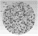
이제 도 1A-C를 참조하면, 고 유전상수 복합 재료(100A-C)에 있어서 입자 분배물의 다양한 구체예가 도시된다. 보이는 바와 같이 복합 재료(100A-C)는 중합체 결합제(108)에 의해 함께 결합된 다양한 유전 입자(102-106) 중 적어도 하나의 분배물을 포함한다. 예시의 목적을 위해, 입자(102-106)는 도 1A-C에서 일반적인 패턴의 분배를 가지는 것으로 나타난다. 다양한 구체예에서, 입자(102-106)는 무작위로 배열되어 무작위 입자 충전을 야기할 수 있다. 입자(102-106)의 무작위 배열에도 불구하고, 복합물질의 입자 밀도 및, 유전 상수 및 유전 강도를 비롯한 다른 특성이 재료 전체에 걸쳐 균일하도록, 입자는 교반 및 혼합에 의해 복합 재료 전체에 걸쳐 균일하게 분산된다.Referring now to FIGS. 1A-C, various embodiments of particle distributions for high dielectric constant
복합 재료는 임의의 고 유전상수의 입자를 이용하여 제조될 수 있다. 바람직하게는, 입자(102-106)는 식 Ba(1 - x)SrxTiO3를 갖는 바륨 티타네이트(BaTiO3), 스트론튬 티타네이트(SrTiO3), 또는 바륨 스트론튬 티타네이트(BST) 입자를 포함하지만, 이에 제한되지 않는 세라믹이다. BST 입자는 독립적인 입자로서 포함될 수 있거나 복합 재료(100) 내에 BaTiO3 입자 복합물질의 구성성분으로서 포함될 수 있다. 복합물질 입자를 위한 다른 적절한 재료는 식 Pb[ZrxTi1 -x]O3(여기서 0≤x≤1)를 갖는 세라믹 페로브스카이트인 납 지르코네이트 티타네이트(PZT)를 포함한다. 또한, 다른 페로브스카이트 재료, 비-페로브스카이트 재료, 및 비-선형 강유전성(ferroelectric) 또는 항-강유전성 재료가 또한 사용될 수 있다.Composite materials can be made using particles of any high dielectric constant. Preferably, particles 102-106 may contain barium titanate (BaTiO 3 ), strontium titanate (SrTiO 3 ), or barium strontium titanate (BST) particles having the formula Ba ( 1-x ) Sr x TiO 3 . Ceramics, including but not limited to. BST particles may be included as independent particles or may be included as a component of the BaTiO 3 particle composite material in
페로브스카이트 입자가 바람직하며, 이는 이들이 자기저항성(magnetoresistance), 견고한 유전 특성, 및 특히 단위 셀이 정방정계 구조를 가지는 경우 격자 구조의 고유한 극성과 같은 많은 특징을 보유하기 때문이다. 게다가, 페로브스카이트 구조에 내재된 결합각의 유연성은 특정한 전기 분야에서 요망될 수 있는 얀-텔러(Jahn-Teller) 뒤틀림을 비롯한 다양한 분자의 뒤틀림을 허용한다.Perovskite particles are preferred because they possess many features such as magnetoresistance, robust dielectric properties, and inherent polarity of the lattice structure, especially when the unit cell has a tetragonal structure. In addition, the flexibility of the bonding angles inherent in the perovskite structure allows for the distortion of various molecules, including Jahn-Teller distortion, which may be desired in certain electrical applications.
또한, 입자(102-106)는 내화성 세라믹 입자, 비-내화성 세라믹 입자, 또는 이들의 조합일 수 있다. 세라믹 입자(102-106)는 복합 재료의 유전율의 비교 안정성을 보장하기 위해, 입자의 퀴리(Curie) 온도가 복합 재료(100A-C)에 대해 고려되는 작업 온도와 크게 차이나도록 선택될 수 있다. 예를 들면, 최종 복합 재료의 작업 온도와 약 20℃ 이상 차이나는 퀴리(Curie) 온도를 가지는 입자(102-106)가 선택될 수 있다. 대안적으로, 세라믹 입자(102-106)는 복합 재료의 유전 상수를 최대화하기 위해, 입자의 퀴리(Curie) 온도가 복합 재료(100A-C)에 대해 고려되는 작업 온도이거나 그 부근이 되도록 선택될 수 있다. 게다가, 복합 재료의 유전 강도 및 유전 상수가 피크값이거나 아니면 안정하게 되는 온도 범위를 넓히기 위해, 다양한 퀴리(Curie) 온도를 가지는 세라믹 입자(102-106)가 선택될 수 있다.In addition, the particles 102-106 can be refractory ceramic particles, non-refractory ceramic particles, or a combination thereof. The ceramic particles 102-106 may be selected such that the Curie temperature of the particles differs significantly from the working temperature contemplated for the
비록 도 1A-C에서는 구체(spherical)로 나타나지만, 세라믹 입자(102-106)는 구체 및 불규칙적인 모양을 포함하지만 이에 제한되지 않는 다양한 모양을 가질 수 있다. 도 2-3은 각각 입방체 및 구체 입자의 분배물을 가지는 복합 재료(100D) 및 (100E)를 도시한다. 도 4는 복합 재료(100B)와 유사한 복합 재료를 제조하기 위해 사용될 수 있는 입자(102 및 104)의 혼합물(200)을 도시한다. 모든 입자(102-106)에 있어서 불규칙적인 모양이 바람직하며, 이는 불규칙적인 모양이 전형적으로 높은 충전 밀도를 가져오며, 이는 다시 복합 재료(100A-E)에 대해 더 높은 유전 상수를 생성하기 때문이다. 입자(102-106)가 임의의 모양일 수 있기 때문에, 입자 크기를 언급할때 사용되는 용어 직경은 입자의 명목적 규모를 가리킬 수 있다. 예를 들면, 불규칙적인 모양의 입자의 직경은 입자의 평균 직경을 가리킬 수 있다. 유사하게, 뚜렷한-입방체인 입자의 직경은 입자 모서리의 길이를 가리킬 수 있다. 타원체와 같은 다른 입자 모양에 있어서, 직경은 가장 긴 축 또는 가로 길이를 가리킬 수 있다.Although shown as spherical in FIGS. 1A-C, ceramic particles 102-106 may have a variety of shapes including, but not limited to, spheres and irregular shapes. 2-3 illustrate
도 1A에 나타난 바와 같은 복합 재료(100A)는 직경으로 대략 2 nm 미만부터 대략 2000 ㎛ 초과에 달하는 유전 입자(102-106)의 삼중모드 분배를 갖는다. 각각의 크기 범위 내의 입자(102-106)는 균일할 수 있다. 대안적으로, 각각의 크기 범위 내의 입자는 그 크기 범위 이내에서의 임의의 다양한 크기일 수 있다. 유사하게, 각각의 크기 범위 이내(즉 소형, 중간, 및 대형) 및 각각의 크기 범위에 걸치는 입자(102-106)는 동일한 재료 또는 상이한 재료 및 조성을 가질 수 있다. 예를 들면, 바륨 티타네이트, 스트론튬 티타네이트, 및 바륨 스트론튬 티타네이트 입자의 조합이 각각의 크기 범위 이내 및 크기 범위에 걸쳐서 사용될 수 있다.
입자 크기의 분배 및 범위는 복합물질(100A-C)의 세라믹 충전율 및 유전 상수를 증가시키기 위해 선택된다. 임의의 크기의 세라믹 입자가 사용될 수 있는 반면, 가장 작은 입자(102)에 대한 범위는 제조 한계에 의해, 그리고 소형 입자의 응집이 복합 재료(100A-C)의 유전 특징을 저하시킬 것이므로, 소형 입자가 응집하지 않게 하려는 요구에 의해 제약될 수 있다. 한 구체예에서, 소형 입자(102)는 대략 50 nm 직경이며; 그렇지만, 2 nm 만큼 작은 더 작은 입자가 사용될 수 있다. 반대로, 50 nm보다 더 큰 입자가 소형 입자(102)로서 사용될 수 있다. 그렇지만, 입자의 충전을 최대화하기 위해 가장 작은 수득가능한 나노입자가 사용되는 것이 바람직하다.The distribution and range of particle sizes are chosen to increase the ceramic fill factor and dielectric constant of the
전형적으로, 가장 큰 입자(106)는 최종 복합 재료(100A-C)의 두께와 관련한 실용적인 고려에 의해서만 제한된다. 예를 들면, 임의의 단일 대형 입자(106)가 복합 재료(100A-C)의 총 두께의 약 10% 미만이거나 이와 동일한 것이 바람직하다. 예를 들면, 대략 2-2.5mm 두께의 복합 재료는 대략 220 ㎛ 크기의 대형 입자(106)를 이용하여 제작될 수 있다. 유사하게, 얇은 복합물질 막은 더 작은 규모를 갖는 대형 입자(106)를 이용하여 제조될 수 있다.Typically, the
한 구체예에서, 중간 입자(104)를 위한 크기 범위는 중간 입자 크기의 범위가 가장 작은 입자(102)에 대한 크기 범위 및 대형 입자(106)에 대한 크기 범위로부터의 공통 인자에 의해 구별되도록 계산된다. 예를 들면, 50 nm 소형 입자(102) 및 50 ㎛ 대형 입자(106)를 이용하는 경우, 대형 입자 크기 대 소형 입자 크기의 비는 1000이다. 중간 입자(104)의 크기 범위를 결정하기 위해, 1000의 제곱근(대략 31.6)이 대략 1.58 ㎛의 중간 입자크기를 결정하기 위한 인자로서 사용된다(즉 50 nm x 31.6 또는 50 ㎛/ 31.6). 다른 구체예에서, 중간 입자(104)에 대한 크기 범위는 대형 입자(106)의 크기 범위에 가깝거나 소형 입자(102)의 크기 범위에 가까울 수 있다.In one embodiment, the size range for the
각각의 요망되는 크기 분배 내의 세라믹 입자(102-106)는 상업적으로 구매할 수 있거나, 대안적으로, 대형 세라믹 입자를 요망되는 크기로 분쇄함에 의해 제조될 수 있다. 다양한 구체예에서, 입자 크기의 분배는 다양한 응결적이거나 폭발적인 제조 공정에서 사용되는 것들과 유사한 식을 이용하여 최적화될 수 있다. 또한, 세라믹 입자는 사용 전에 소결될 수 있다.Ceramic particles 102-106 in each desired size distribution can be purchased commercially, or alternatively, can be prepared by grinding large ceramic particles to the desired size. In various embodiments, the distribution of particle size can be optimized using equations similar to those used in various condensation or explosive manufacturing processes. In addition, the ceramic particles may be sintered before use.
예시이며 제한이 아닌 방식으로, 복합 재료(100A)는 약 40 ㎛ 내지 약 220 ㎛의 직경을 가지는 BaTiO3 대형 입자(106), 약 500 ㎛ 내지 약 5 ㎛의 직경을 가지는 BaTiO3 중간 입자(104) 및 약 500 nm 미만의 직경을 갖는 BaTiO3 또는 BST로 구성된 소형 입자(102)로 이루어진 세라믹 입자의 삼중모드 분배물을 내포할 수 있다. 한 구체예에서, 가장 작은 입자는 대략 2 nm 이하의 직경을 가질 수 있다.In an illustrative and non-limiting manner,
바람직하게는, 각각의 크기 분배 비율 그리고 각각의 입자 크기에 대한 부피율은 복합 재료(100A-C) 내의 최대 충전율을 얻고 중합체 결합제(108)의 부피를 최소화하기 위해 계산된다. 본 명세서에 사용된, 부피율은 구성성분(예컨대 입자(들) 또는 중합체)의 부피를 혼합물의 모든 구성성분의 부피로 나눈 것을 가리킨다. 예를 들면, 입자의 삼중모드 분배를 가지는 복합 재료(100A)의 한 구체예에서, 대형 입자(106), 중간 입자(104), 및 소형 입자(102)의 비는, 각각, 대략 65:25:10이고 여기서 대형 입자가 복합물질 질량 및 부피의 가장 큰 비율을 차지한다. 또다른 예에서, 대략 65-80 %의 대형 입자, 대략 15-20%의 중간 입자, 및 대략 5-15%의 소형 입자의 비율이 사용될 수 있다. 임의의 다른 비율이 사용될 수 있지만, 입자의 분배를 위한 비율은 입자의 크기 및 입자의 각각의 분배에 대한 공극율을 기초로 결정되는 것이 바람직하다. 따라서, 가장 큰 입자(106)는 전형적으로 가장 큰 비율의 질량 및 부피를 가지는 반면, 중간 크기 입자는 두 번째로 가장 큰 비율을 갖는다.Preferably, each size distribution ratio and volume fraction for each particle size are calculated to obtain the maximum filling rate in the
다양한 다른 구체예에서, 복합 재료는 도 1C에 나타난 바와 같은 단일 크기 범위 이내의 입자로 이루어질 수 있거나, 복합 재료는 도 1B에 나타난 바와 같은 입자의 이중 모드 분배를 가질 수 있다. 사중모드 이상을 포함하는 다른 분배물이 사용될 수 있다. 또한, 복합 재료를 형성하기 위해 사용되는 입자들의 크기가 "인접한(adjacent)" 크기 범위일 필요는 없다. 예를 들면, 복합 재료는 도 4에 나타나는 바와 같이, 대형 입자(106) 및 소형 입자(102)의 혼합물을 이용하여 형성될 수 있다.In various other embodiments, the composite material may consist of particles within a single size range as shown in FIG. 1C, or the composite material may have a bimodal distribution of particles as shown in FIG. 1B. Other distributions may be used including more than quad mode. In addition, the size of the particles used to form the composite material need not be in the "adjacent" size range. For example, the composite material can be formed using a mixture of
다양한 구체예에서, 세라믹 입자(102-106)의 표면은 입자와 중합체 결합제 사이의 직접 결합이 증가되도록 관능화된다. 표면이 관능화될 수 있는 다수의 방식이 존재한다. 예를 들면, 각각의 입자(102-106)는 도 5A-C에 나타나는 바와 같이, 표면(300)을 히드록실화하여 히드록실 (-OH) 기(302)를 도입함으로써 관능화될 수 있다. 히드록실 기(302)는 입자(102-106)를 과산화수소로 처리함으로써 도입될 수 있으며; 하지만, 입자를 과도하게 개질함 없이 입자 표면을 히드록실화하기 위한 임의의 다른 적절한 방법이 사용될 수 있다.In various embodiments, the surfaces of the ceramic particles 102-106 are functionalized to increase the direct bond between the particles and the polymeric binder. There are a number of ways in which the surface can be functionalized. For example, each particle 102-106 can be functionalized by introducing a hydroxyl (—OH)
세라믹 입자(102-106)의 표면이 히드록실화되었으면, 예를 들어, 실란 및 지르코네이트가 세라믹 입자의 표면을 관능화하기 위해 사용될 수 있다. 예시이며 제한이 아닌 방식으로, 비닐트리메톡시실란 및 물(306)의 부산물과 같은 실란-계 중합체 전구체(304)의 가열된 용액이 입자 표면 및 결합 재료를 관능화하고 직접 결합되게 하는 두 가지 표면 처리로서 작용하여 모든 세라믹 표면(102-106) 사이에 고도로 가교-연결된 구조(308)를 형성할 수 있다.If the surfaces of the ceramic particles 102-106 have been hydroxylated, for example, silane and zirconate may be used to functionalize the surface of the ceramic particles. In an illustrative and non-limiting manner, there are two ways in which heated solutions of silane-based
중합체 결합제Polymer binder
중합체 결합제(108)는 시아네이트 에스테르 또는 폴리시아누레이트를 포함하지만 이에 제한되지 않는 임의의 유전성 중합체일 수 있다. 바람직하게는, 중합체 결합제(108)는, 비록 다른 중합체 재료가 사용될 수 있지만, 비가역적으로 경화될 수 있는 중합체 재료이다. 중합체 결합제(108)는 또한 바람직하게는, 작은 분자 크기를 가지고, 입자 표면에 직접 결합할 수 있고, 고도로 가교-연결된 중합체 네트워크를 형성할 수 있는 임의의 중합체 또는 중합체 전구체일 수 있다. 대안적으로, 다른 구체예는 이들 특징이 반드시 있지는 않은 중합체 또는 중합체 전구체를 사용할 수 있다. 이들은 특히 겔화 중합체 및 셀룰로오스-계 중합체를 포함한다.The
한 구체예에서, 중합체 결합제(108)는 인-시추(in-situ)로 중합되어 세라믹 입자(102-106)에 직접 결합하는 중합체 전구체로부터 형성된다. 다른 구체예에서, 중합체 결합제(108)는 물과 같은 특정 용매의 존재에서 팽윤하는 아가(agar)와 같은 겔화 중합체 전구체의 용해로부터 형성된다. 이들 구체예에서, 중합체 결합제(108)는 겔화 중합체 전구체, 용매, 및 입자(102-106)의 혼합물이 냉각되고 용매가 제거될 때 형성된다.In one embodiment, the
바람직하게는, 중합체 결합제(108) 또는 중합체 전구체는 금속 입자를 내포하지 않는다. 비-금속성 중합체 매트릭스를 가지는 복합 재료는 복합 재료의 더 높은 파괴 전압 및 더 긴 수명을 가능하게 한다.Preferably, the
중합체 전구체를 사용하는 경우에, 중합체 전구체는 세라믹 입자(102-106)의 분배물과 혼합되고 분배물을 통해 침투하여 각각의 입자 표면에 접촉되게 된다. 예를 들면, 실란-계 중합체 전구체, 가령 트리알콕시실란 및 더 상세하게는 비닐트리메톡시실란, 트리에톡시비닐실란, 아미노프로피트리에톡시실란, 또는 이들의 조합이, 중합체 결합제(108)를 형성하기 위해 사용될 수 있다. 또한, 중합되어 폴리실세스퀴옥산을 형성하는 다른 실란, 지르코네이트 또는 티타네이트-계 커플링제 또는 중합체 전구체가 사용될 수 있다. 바람직하게는, 중합체 전구체는 이들이 혼합물을 통해 입자 표면(300)으로 침투하여 입자(102-106)의 표면에 직접 결합할 수 있게 하는 물리적 및 화학적 특징을 갖는다. 바람직하게는, 중합체 전구체는 세라믹 입자 사이로 유동하여 입자 표면(300)을 코팅하기에 충분히 낮은 점도를 갖는다. 복합 재료(100A-E)의 형성 동안 가해지는 압력 및 임의로, 열 하에서, 중합체 결합제(108) 및/또는 중합체 전구체는 세라믹 입자 표면(300) 상의 나노미터 및 나노미터-미만 수준의 결함부분에 침투한다. 중합체 결합제(104)는 따라서 입자(102-106)의 표면 경계에 있는 임의의 기공을 제거한다. 예시이며 제한이 아닌 방식으로, 실란, 티타네이트, 및/또는 지르코네이트-계 중합체 전구체가 세라믹 입자 표면(300) 사이의 직접 결합을 촉진하고, 매트릭스(308)와 같은 고도로 가교-연결된 중합체 매트릭스를 형성하기 위해 사용된다.In the case of using a polymer precursor, the polymer precursor mixes with the distribution of ceramic particles 102-106 and penetrates through the distribution to come into contact with each particle surface. For example, silane-based polymer precursors, such as trialkoxysilanes and more particularly vinyltrimethoxysilane, triethoxyvinylsilane, aminopropyethoxysilane, or combinations thereof, may form
다양한 구체예에서, 최종 복합 재료(100A-E)의 유전 상수는 선택된 중합체 결합제(104)에 따라 사용을 위해 최적화될 수 있다. 한 예에서, 바람직한 실란-계 중합체 전구체는 무기 세라믹 입자(102-106)에의 결합을 위한 추가적인 커플링제가 필요하지 않도록 전형적인 실란-계 중합체 전구체보다 더 높은 실란 농도를 갖는다. 추가적인 중합체 고분자와 같은 외부 결합 첨가제의 제거는 세라믹 충전율을 더욱 향상시키며, 이를 통해 복합 재료(100A-E)의 유전 상수를 증가시킨다. In various embodiments, the dielectric constant of the final
한 구체예에서, 중합체 결합제(108)는 시아노레진으로 구성된다. 시아노레진 결합제는 수백 MHz의 주파수에서 약 10 내지 약 55로 달라질 수 있는 유전 상수를 가지는 복합 재료(100A-E)를 생성할 것이다. 예를 들면, 중합체 결합제는 일본 도쿄의 Shin-Etsu Chemical Co., Ltd에 의해 제조되는 CR-S와 같은 시판되는 제품일 수 있다. CR-S는 고 유전상수, 양호한 강도를 가지는 시아노에틸화 셀룰로오스 중합체이고 가공이 가능하다.In one embodiment, the
또다른 구체예에서, 복합 재료(100A-E)의 유전 상수는 전형적으로 아가의 형태인 겔화 중합체 전구체, 바람직하게는 아가로스를 사용함으로써 증가된다. 겔화 중합체는 자연 유래이거나 합성으로 제조된 바이오중합체일 수 있다. 겔화 중합체 전구체는 용매에 용해되고 세라믹 입자(102-106)의 분배물과 함께 복합물질 몰드 내에 압축된다. 복합물질 몰드는 이후 용매의 존재에서 겔화 중합체 전구체가 팽윤되게 하는 압력 하에서 냉각된다. 복합물질 몰드는 이후 용매를 제거하기 위해 중합체 전구체의 용해 온도 미만의 온도로 재가열되고, 이를 통해 중합체 결합제(108)가 형성된다. 그 결과, 중합체 결합제(108)의 부피는, 복합 재료의 전체 구조의 변화 없이, 앞서 팽윤된 중합체 전구체의 부피보다 작아진다.In another embodiment, the dielectric constant of
감소된 부피의 중합체 결합제(108)는 세라믹 입자(102-106) 주변에 공극 또는 공동을 형성할 수 있다. 유전성 액체는 이후 복합 재료 내부에 스며들어 복합 재료 내부의 모든 공동 또는 공극을 채우고 제거하며 세라믹 입자(102-106)의 표면(300)을 둘러싼다. 젤라틴, 카라긴(carrageen), 또는 유전성 액체의 존재에서는 흡수하거나 팽윤되지 않지만, 용매의 존재에서 팽윤될, 중합체 결합제(108)를 위한 임의의 다른 전구체를 포함하는 다른 중합체 전구체가 또한 사용될 수 있다.The reduced volume of
유전성 액체Dielectric fluid
유전성 액체는 복합 재료에 스며들어 복합 재료 내에서 임의의 잔여 공극에 침투하고 채울 수 있는 충전 유체다. 유전성 유체는 또한 세라믹 입자의 임의의 노출된 표면(300)을 나노미터 및 나노미터-미만 수준으로 코팅한다. 유전성 액체의 부가는 재료에서 공극을 제거함으로써, 복합 재료의 다공성을 줄임으로써, 그리고 세라믹 입자의 경계 계면을 향상시킴으로써, 복합물질의 유전 상수 및 유전 강도 둘다를 증가시킬 수 있다. 유전성 유체는 재료를 유전성 유체 내에 침지시킴으로써 형성된 복합 재료 내에 스며들 수 있다. 유전성 유체는 모세관 작용 단독을 통해 복합 재료에 더욱 스며들 수 있거나, 진공 또는 다른 가압 시스템의 보조로 재료에 들어갈 수 있다.The dielectric liquid is a filling fluid that can penetrate the composite material and penetrate and fill any residual voids in the composite material. The dielectric fluid also coats any exposed
한 구체예에서, 유전성 유체는 고 유전상수를 갖는다. 예를 들면, 고 유전상수는 물, 글리세린, 및 알킬렌 카르보네이트 가령 에틸렌 카르보네이트, 프로필렌 카르보네이트, 글리세린 카르보네이트, 부틸렌 카르보네이트, 및 이들의 조합일 수 있으나, 이에 제한되지 않는다. 역으로, 저 유전 상수를 가지는 유전성 유체가 사용되어 복합물질의 유전 강도를 증가시킬 수 있는 반면, 더 적은 정도로, 복합 재료의 유전 상수를 증가시킨다. 저 유전 상수를 갖는 예시적인 유전성 유체는 전기 절연체에서 사용되는 것들과 같은 오일을 포함한다. 바람직하게는, 유전성 액체는 고 유전상수, 저 점도, 저 유전성 손실, 및 저 증발률을 갖는다.In one embodiment, the dielectric fluid has a high dielectric constant. For example, the high dielectric constant may be, but is not limited to, water, glycerin, and alkylene carbonates such as ethylene carbonate, propylene carbonate, glycerin carbonate, butylene carbonate, and combinations thereof. It doesn't work. Conversely, a dielectric fluid with a low dielectric constant can be used to increase the dielectric strength of the composite, while to a lesser extent the dielectric constant of the composite material. Exemplary dielectric fluids having low dielectric constants include oils such as those used in electrical insulators. Preferably, the dielectric liquid has a high dielectric constant, low viscosity, low dielectric loss, and low evaporation rate.
유전성 유체는 중합체 결합제의 인-시추(in-situ) 중합에 의해 형성된 복합 재료, 그리고 겔화 중합체 전구체로부터 형성된 복합 재료 내에 스며들 수 있다. 또한, 유전성 액체가 스며든 복합 재료는 유전성 액체의 증발을 방지 또는 감소시키기 위해 임의로 임의의 적절한 기체-불투과성 재료로 코팅될 수 있다. 예를 들면, 복합 재료는 실란, 티타네이트, 및/또는 지르코네이트-계 중합체로 코팅될 수 있다.The dielectric fluid may permeate into the composite material formed by in-situ polymerization of the polymeric binder and the composite material formed from the gelling polymer precursor. In addition, the composite material impregnated with the dielectric liquid may be optionally coated with any suitable gas-impermeable material to prevent or reduce evaporation of the dielectric liquid. For example, the composite material may be coated with silane, titanate, and / or zirconate-based polymers.
또다른 구체예에서, 100 내지 1000 MHz의 주파수에서 대략 100의 유전 상수를 가지는 복합 재료는 인-시추(in-situ) 중합 후에 폴리실세스퀴옥산을 형성하는 실란, 티타네이트, 및 지르코네이트 화학물질을 이용하여 제조될 수 있다. 이들 화합물을 내포하고 폴리실세스퀴옥산을 생성하는 중합체 전구체는 작은 분자 크기를 가지며 세라믹 입자 표면에 직접 결합되고 고도로 가교-연결된 중합체 네트워크를 형성하기에 적절하다.In another embodiment, composite materials having a dielectric constant of approximately 100 at frequencies of 100-1000 MHz include silanes, titanates, and zirconates that form polysilsesquioxanes after in-situ polymerization. It can be prepared using chemicals. Polymeric precursors containing these compounds and producing polysilsesquioxanes have a small molecular size and are suitable for forming a highly cross-linked polymer network that is directly bonded to the ceramic particle surface.
또다른 구체예에서, 100 내지 1000 MHz의 주파수에서 대략 550의 유전 상수를 가지는 복합 재료는 물의 존재에서 팽윤하는 겔화 중합체 전구체를 이용하여 제조될 수 있다. 바람직하게는, 겔화 중합체 전구체는 물의 존재에서 팽윤하지만 알킬렌 카르보네이트의 존재에서는 팽윤하지 않는다. 게다가, 바람직한 겔화 중합체 전구체는 세라믹 입자(102-106)와 혼합되기 전에 용해될 수 있고, 건조되면 높은 강도를 가지고, 높은 용해 온도를 가지며, 바이오재료이다.In another embodiment, a composite material having a dielectric constant of approximately 550 at a frequency of 100-1000 MHz can be prepared using a gelling polymer precursor that swells in the presence of water. Preferably, the gelling polymer precursor swells in the presence of water but does not swell in the presence of alkylene carbonate. In addition, the preferred gelling polymer precursor can be dissolved before mixing with the ceramic particles 102-106, has a high strength when dried, has a high dissolution temperature, and is a biomaterial.
복합 재료의 제작Fabrication of Composites
전술한 바와 같이, 세라믹 입자(102-106)는 상업적으로 입수될 수 있거나 분쇄 공정 동안 형성될 수 있다. 한 구체예에서, 세라믹 입자가 분쇄에 의해 형성되는 경우, 메틸 에틸 케톤과 같은 용매가 입자의 응집을 막기 위해 사용된다. 아세톤, 메틸 프로필 케톤, 폴리메틸메타크릴레이트, 또는 디클로로메틸렌을 포함하지만, 이에 제한되지 않는 추가적인 용매가 또한 사용될 수 있다. 또한, 응집을 막기 위해 계면활성제가 분쇄 공정에 부가될 수 있다. 예시이며 제한이 아닌 방식으로, 계면활성제는 올레산, 알킬벤젠-설폰산, 또는 포스페이트 에스테르일 수 있다. 바람직하게는, 계면활성제는 극성 첨가제이다. 또한, 계면활성제는 중합체 결합제와의 결합을 증진하기 위해 세라믹 입자의 표면을 관능화하도록 작용할 수 있다.As mentioned above, the ceramic particles 102-106 may be commercially available or may be formed during the grinding process. In one embodiment, when the ceramic particles are formed by milling, a solvent such as methyl ethyl ketone is used to prevent the agglomeration of the particles. Additional solvents may also be used, including but not limited to acetone, methyl propyl ketone, polymethylmethacrylate, or dichloromethylene. In addition, surfactants may be added to the grinding process to prevent aggregation. In an illustrative and non-limiting manner, the surfactant can be oleic acid, alkylbenzene-sulfonic acid, or phosphate esters. Preferably the surfactant is a polar additive. In addition, the surfactant may act to functionalize the surface of the ceramic particles to promote bonding with the polymeric binder.
다양한 구체예에서, 세라믹 입자는 중합체 전구체 또는 결합제와 혼합되기 전에 소결되어 경화된 입자를 생성할 수 있다. 소결된 입자는 감소된 다공성을 가지고, 이는 입자 내 공극을 감소시키고, 입자의 입자 비질량 편차를 증가시키며, 입자에 중합체 전구체 또는 결합제가 침투하는 것을 방지하거나 적어도 최소화할 것이다.In various embodiments, the ceramic particles can be sintered to produce cured particles prior to mixing with the polymer precursor or binder. The sintered particles have a reduced porosity, which will reduce voids in the particles, increase the particle specific mass deviation of the particles, and prevent or at least minimize penetration of the polymer precursor or binder into the particles.
한 구체예에서, 세라믹 입자 및 실란, 티타네이트, 또는 지르코네이트, 가령 비닐트리메톡시실란 또는 트리에톡시비닐실란을 내포하는 중합체 전구체의 혼합물은 추가로 물과 혼합되고 교반되면서 약불로 제조된다. 예를 들면, 혼합물은 약 100℃ 내지 약 200℃의 온도에서 제조될 수 있다. 혼합물의 가열은 세라믹 입자의 표면이 관능화되는 속도를 증가시키며 폴리실세스퀴옥산 네트워크의 형성 속도를 증가시킨다.In one embodiment, a mixture of ceramic particles and polymer precursors containing silane, titanate, or zirconate, such as vinyltrimethoxysilane or triethoxyvinylsilane, is further prepared on low heat with mixing and stirring with water. . For example, the mixture may be prepared at a temperature of about 100 ° C to about 200 ° C. Heating of the mixture increases the rate at which the surface of the ceramic particles is functionalized and increases the rate of formation of the polysilsesquioxane network.
복합 재료는 추가로 재료를 성형하기 위한 다이에서 건조 가압에 의해 형성된다. 예를 들면, 세라믹 입자(102-106), 중합체 전구체, 및 임의의 계면활성제로 구성된 페이스트가 다이에서 가압된다. 전형적으로, 다이는 기계식 또는 유압식 수단을 이용하여 가압되어 페이스트를 다이의 모양으로 압축한다. 다른 구체예에서, 복합 재료는 등방향 가압에 의해 형성될 수 있고, 여기서 페이스트는 몰드로서 기능하는 유연한 막을 이용하여 등방향으로 가압된다. 복합물질 페이스트를 가압하는 것이 바람직한 제조 방법이지만, 복합 재료는 또한 회전 코팅 또는 용해 주조(solution casting)에 의해 형성될 수 있다.The composite material is further formed by dry pressing in a die for forming the material. For example, a paste composed of ceramic particles 102-106, a polymer precursor, and any surfactant is pressed in the die. Typically, the die is pressurized using mechanical or hydraulic means to compress the paste into the shape of the die. In another embodiment, the composite material can be formed by isotropic pressing, where the paste is pressed in the isotropic direction using a flexible membrane that functions as a mold. Pressing the composite paste is a preferred manufacturing method, but the composite material may also be formed by spin coating or solution casting.
다양한 구체예에서, 복합 재료는 평방 인치당 (PSI) 약 100 파운드 내지 평방 인치당 30 메트릭 톤(metric ton)을 훨씬 넘는 압력으로 가압된다. 복합 재료(100)는 비록 다른 가압 기술이 사용될 수 있지만, 이중방향 또는 단방향 가압 기술에 의해 형성될 수 있다. 한 구체예에서, 이중방향 가압은 복합 재료 내에 형성될 수 있는 밀도 구배를 제거하고 복합 재료 전체에 걸쳐 균일한 유전 상수를 제공한다. 역으로, 구배 밀도가 바람직한 경우, 입자의 밀도는 복합 재료를 제조하기 위해 단방량 가압 공정을 이용함으로써 복합 재료 전반에 걸쳐 달라질 수 있다.In various embodiments, the composite material is pressurized to a pressure of about 100 pounds per square inch (PSI) to well over 30 metric tons per square inch.
페이스트를 가압한 후에 또는 동시에, 다이는 중합체 전구체의 인-시추(in-situ) 중합을 촉진하기 위해 가열되어, 이를 통해 중합체 결합제(104)를 형성할 수 있다. 다른 구체예에서, 중합체 전구체는 자외선(UV) 복사를 이용하거나 또는 촉매를 부가하여 화학적인 중합을 일으켜서 중합되거나 경화될 수 있다. 한 구체예에서, 중합체 결합제(108)는 세라믹 입자(102-106)의 표면에 직접 결합하고 고도로-가교연결된 구조를 형성한다. 따라서, 결합제로서 기능하는 추가적인 중합체가 필요하지 않다.After pressing the paste or at the same time, the die may be heated to promote in-situ polymerization of the polymer precursor, thereby forming the
다양한 구체예에서, 고 유전상수를 가지는 유전성 유체는 중합체 전구체의 중합 후에 부가되어 중합체 결합제(108)와 세라믹 입자(102-106) 사이에 잔여할 수 있는 임의의 공극을 채운다. 특히, 충전 액체는 세라믹 입자(102-106)의 표면(300) 상에서 경계 계면을 나노미터 및 나노미터-미만 수준으로 향상시킨다.In various embodiments, the dielectric fluid having a high dielectric constant is added after polymerization of the polymer precursor to fill any voids that may remain between the
최종 복합 재료는 스며든 유전성 액체의 증발을 방지하고 복합 재료의 다공성을 감소시키기 위해 코팅될 수 있다. 복합 재료는 이후 바람직한 크기로 절단, 가공, 및 또는 연마될 수 있다. 추가적인 마감공정은 하나 이상의 전극을 최종 복합 재료에 부가하는 것을 포함할 수 있다. 예시의 방식으로, 전극은 백금, 금, 또는 임의의 적절한 전도성 재료일 수 있다. 한 구체예에서, 전극은 복합 재료 상에 직접 스퍼터링(sputtering)되어 전극과 복합 재료 사이의 임의의 공기 간극을 제거한다.The final composite material can be coated to prevent evaporation of the infiltrating dielectric liquid and to reduce the porosity of the composite material. The composite material may then be cut, processed, or polished to the desired size. Additional finishing may include adding one or more electrodes to the final composite material. By way of example, the electrode may be platinum, gold, or any suitable conductive material. In one embodiment, the electrode is sputtered directly onto the composite material to remove any air gaps between the electrode and the composite material.
다양한 구체예에서, 인-시추(in-situ) 중합 공정은 적어도 80%의 입자 충전율이 성취되게 하고 상응하게 더 높은 유전 상수가 관찰되게 한다. 인-시추(in-situ) 중합 공정은 또한 손실 탄젠트 및 유전 상수가 동시에 복합 재료(100)의 최종 적용분야에 의해 결정되는 요망되는 요건으로 조정되도록 한다. 입자의 매트릭스에 결합하기 위해 사용되는 폴리실세스퀴옥산은 입자에 결합하기 위한 고점도 중합체 및 에폭시에 대한 필요성을 제거한다.In various embodiments, the in-situ polymerization process allows at least 80% particle filling rate to be achieved and a correspondingly higher dielectric constant be observed. In-situ polymerization processes also allow the loss tangent and dielectric constant to be adjusted to the desired requirements simultaneously determined by the final application of the
복합 재료Composite material
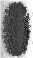
가공된 고 유전상수 복합 재료의 예가 도 6-9에 나타난다. 도 6에 나타나는 바와 같이, 복합 재료(100A-E)는 고체 디스크(400)로 절단되고 가공될 수 있다. 눈금자(402)가 규모감을 제공하기 위해 도시되고; 하지만, 복합 재료는 임의의 크기 및 배치로 제조될 수 있다. 도 7은 추가적인 요소를 수용하기 위한 기재(500)로 가공된 복합 재료의 사진이다. 도 8A는 많은 고리형 디스크(600A-G)로 가공된 복합 재료를 도시한다. 도 8B에 나타나는 바와 같이, 고리형 디스크(600A-G)는 봉(602)에 끼워지고 잠금장치(604A-B)에 의해 함께 고정될 수 있다. 도 9는 디스크(700)로서 제조된 복합 재료를 도시한다. 또한, 단일 박막 층 시트 또는 다중-층 복합물질 커패시터가 또한 고 유전 복합 재료를 이용하여 제조될 수 있다.Examples of processed high dielectric constant composite materials are shown in FIGS. 6-9. As shown in FIG. 6, the
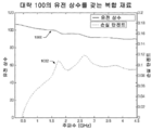
도 10에 나타나는 바와 같이, 대략 100의 평균 유전 상수를 가지는 복합 재료에 대한 유전 상수의 프로파일(1000)은 실제로 200 MHz 내지 4.5 GHz의 주파수 범위에 걸쳐 대략 108 내지 대략 90 또는 +/-10%로 변화한다. 보이는 바와 같이, 전체 주파수 범위에 걸쳐 손실 탄젠트의 프로파일(1002)은 0.12 미만이고 500 MHz 아래에서, 손실 탄젠트는 0.05 미만이다. 전술한 바와 같이, 손실 탄젠트 및 유전 상수는 선택된 입자 혼합물, 제작 도중 가해지는 열 및 압력, 및 열 및 압력이 가해지는 기간에 의해 예정될 수 있다. 한 구체예에서, 2 GHz에서 0.08 미만의 손실 탄젠트가 수득되었지만, 다른 구체예에서, 0.001 미만의 손실 탄젠트가 가능하다. 낮은 손실 탄젠트는 고 유전상수 복합 재료를 이용하기 위한 적용범위의 다양성을 크게 확장한다.As shown in FIG. 10, the
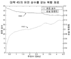
대략 45의 평균 유전 상수를 가지는 복합 재료에 대한 유전 상수 및 손실 탄젠트의 범위가 도 11에 나타난다. 보이는 바와 같이, 유전 상수의 프로파일(1100)은 200 MHz 내지 4.5 GHz의 주파수 범위에 걸쳐 대략 49부터 대략 39까지 달라진다. 전체 주파수 범위에 걸쳐 손실 탄젠트의 프로파일(1102)은 0.14 미만이고 500 MHz 아래에서, 손실 탄젠트는 0.08 미만이다. 도 12는 대략 550의 피크 유전 상수를 가지는 복합 재료에 대한 유전 상수 범위 및 손실 탄젠트 범위의 프로파일(1200)을 도시한다. 보이는 바와 같이, 유전 상수는 200 MHz 내지 4.5 GHz의 주파수 범위에 걸쳐 대략 550부터 대략 400까지 변화한다. 전체 주파수 범위에 걸쳐 손실 탄젠트의 프로파일(1202)은 0.35 미만이고 500 MHz 아래에서, 손실 탄젠트는 대략 0.125 미만이다. 도 10-12에 나타나는 바와 같은 복합 재료의 실제 유전 상수는, 부분적으로는, 측정 방법의 불완전성 및 시험된 복합 재료 및 시험 기기의 표면 결함부분으로 인해, 보이는 것보다 대략 10% 더 높을 수 있다고 생각된다.The range of dielectric constant and loss tangent for a composite material having an average dielectric constant of approximately 45 is shown in FIG. 11. As can be seen, the profile of dielectric constant 1100 varies from approximately 49 to approximately 39 over a frequency range of 200 MHz to 4.5 GHz. The
가동시, 고 유전상수 복합 재료의 전기장은 단일 파괴에 대해 약 1 - 1.84 MV/cm의 범위인 것으로 발견되었다. 본 명세서에 개시된 바와 같은 혼합 기술의 다양함으로 인해, 전기장 파괴 특징은 일부 구체예에서 4 MV/cm를 초과하여 훨씬 향상될 수 있다. 그러므로, 고 유전상수 복합 재료는 200 J/cm3를 초과하여 최대 1000 J/cm3의 에너지 저장 밀도를 가질 수 있다. 한 구체예에서, 고 유전상수 복합 재료는 실온에서 대략 20 J/cm3의 에너지 밀도를 갖는다. 따라서, 단일 층이든 다중층이든, 낮은 손실 커패시터가 본 명세서에 개시된 인 시추(in situ) 중합 공정을 이용하여 제작될 수 있다. 또한, 200 MHz에서 550을 초과하고 20 KHz에서 56000만큼 높은 유전 상수를 가지는 복합 재료가 제조되었다.In operation, the electric field of the high dielectric constant composite material was found to be in the range of about 1-1.84 MV / cm for single failure. Due to the variety of mixing techniques as disclosed herein, the electric field breakdown characteristics may be much improved in excess of 4 MV / cm in some embodiments. Therefore, the high dielectric constant composite material can have an energy storage density of up to 1000 J / cm 3 in excess of 200 J / cm 3 . In one embodiment, the high dielectric constant composite material has an energy density of approximately 20 J / cm 3 at room temperature. Thus, low loss capacitors, whether single or multilayer, can be fabricated using the in situ polymerization process disclosed herein. In addition, composite materials have been produced having dielectric constants in excess of 550 at 200 MHz and as high as 56000 at 20 KHz.
복합 재료에 대한 예시적 용도Example Uses for Composite Materials
고 유전상수 복합 재료(100A-E, 400, 500, 600A-G, 및 700)는 안테나, 커패시터, 고-에너지 저장 장치, 및 고-전압 절연체를 포함하지만 이에 제한되지 않는 다양한 응용분야를 위해 적절하다. 고 유전상수 복합 재료의 고주파 특성은 이들 재료를 안테나 및 마이크로파 기재를 포함하지만 이에 제한되지 않는 무선주파 및 마이크로파 전송 부품을 위한 이상적인 재료가 되게 한다. 고 유전상수 재료는 또한 마이크로파 공동, 고에너지 밀도 커패시터, 및 고주파 커패시터를 조정하기 위해 사용될 수 있다. 예시이며 제한이 아닌 방식으로, 고 유전 복합 재료는 고전력 안테나에서 사용하기에 적절하다. 따라서, 유전성 로딩된 안테나의 크기는 본 개시의 고 유전상수 복합 재료를 포함시킴으로써 최소화될 수 있다. 특히, 복합 재료는 나선형 안테나, 유전 공명기 안테나, 또는 상기 복합 재료의 포함으로 인해 이익이 될 수 있고 그 크기가 줄어들 수 있는 임의의 안테나에 포함될 수 있다. 예를 들면, 한 구체예에 따른, 본 명세서에 개시된 고 유전상수 복합물질을 포함하는 안테나는 크기를 6배 내지 10-배 줄여 제작될 수 있다. 다른 구체예에서, 고 유전상수 복합 재료를 포함하는 안테나는 추-헤링톤(Chu-Harrington) 한계(추(Chu)-한계)에 가까운 규모로 더욱더 작아질 수 있다.High dielectric constant composites (100A-E, 400, 500, 600A-G, and 700) are suitable for a variety of applications, including but not limited to antennas, capacitors, high-energy storage devices, and high-voltage insulators. Do. The high frequency properties of high dielectric constant composite materials make these materials ideal materials for radio frequency and microwave transmission components, including but not limited to antennas and microwave substrates. High dielectric constant materials can also be used to tune microwave cavities, high energy density capacitors, and high frequency capacitors. By way of example and not limitation, high dielectric composite materials are suitable for use in high power antennas. Thus, the size of the dielectric loaded antenna can be minimized by including the high dielectric constant composite material of the present disclosure. In particular, the composite material may be included in a spiral antenna, a dielectric resonator antenna, or any antenna that may benefit from the inclusion of the composite material and whose size may be reduced. For example, an antenna including the high dielectric constant composite material disclosed herein according to one embodiment may be fabricated by reducing the size by 6 to 10 times. In another embodiment, the antenna including the high dielectric constant composite material can be made even smaller on a scale close to the Chu-Harrington limit (Chu-limit).
전형적으로, 안테나의 하나 이상의 규모는 안테나 재료에서 송출하는 전자기파의 파장의 함수이다. 따라서, 주어진 주파수에 있어서 안테나 크기는 대략적으로 유전 상수의 제곱근 분의 일에 비례한다. 또다른 양태에서, 복합 재료(100)는 광대역 안테나를 비롯한 안테나를, 공기 유전체를 이용하는 종래의 안테나의 대략 10분의 1 크기 이하로 제작하기 위해 사용될 수 있다.Typically, one or more magnitudes of the antenna are a function of the wavelength of the electromagnetic waves emitted by the antenna material. Thus, at a given frequency, the antenna size is approximately proportional to the square root of the dielectric constant. In another aspect,
안테나 외에, 복합 재료는 종래의 커패시터의 기능을 향상시키고 크기를 줄이기 위해 사용될 수 있다. 두 점 사이의 정전용량은 이들 두 점을 분리하는 재료의 유전 상수에 비례한다. 고 유전상수를 갖는 복합 재료를 포함함으로써, 주어진 정전용량을 위해 필요한 전극의 면적은 종래의 유전체에 대한 유전 상수의 증가에 비례하여 감소한다. 그러므로, 고 유전상수 복합 재료를 포함하는 커패시터는 종래의 커패시터보다 더 소형으로 제조될 수 있다. 게다가, 커패시터에 저장되는 에너지는 이를 통과하는 전압의 제곱만큼 증가한다. 종래의 고 유전상수 세라믹 재료에 비해 고 절연강도를 갖는 고 유전상수 재료를 포함함으로써, 동일 부피에 저장될 수 있는 에너지가 종래의 고 유전상수 재료보다 유전 강도의 증가의 제곱만큼 증가한다. 커패시터의 에너지 밀도가 유전 상수 및 유전체 내부 전기장의 제곱에 비례하기 때문에, 고 유전상수 및 고 절연강도를 갖는 복합 재료를 포함하는 커패시터 내 에너지 밀도는 종래의 저 유전 상수 재료 및 종래의 고 유전상수 세라믹으로 성취되는 것보다 수십 배 더 높을 수 있다.In addition to the antenna, composite materials can be used to improve the functionality and reduce the size of conventional capacitors. The capacitance between the two points is proportional to the dielectric constant of the material separating these two points. By including a composite material having a high dielectric constant, the area of the electrode required for a given capacitance is reduced in proportion to the increase in the dielectric constant for the conventional dielectric. Therefore, a capacitor including a high dielectric constant composite material can be made smaller than a conventional capacitor. In addition, the energy stored in the capacitor increases by the square of the voltage passing through it. By including a high dielectric constant material having a higher dielectric strength as compared to conventional high dielectric constant ceramic materials, the energy that can be stored in the same volume increases by the square of the increase in dielectric strength than conventional high dielectric constant materials. Since the energy density of the capacitor is proportional to the square of the dielectric constant and the dielectric internal electric field, the energy density in the capacitor, including composite materials having high dielectric constant and high dielectric strength, can be achieved by conventional low dielectric constant materials and conventional high dielectric constant ceramics. Can be tens of times higher than what is achieved.
복합 재료는 또한 고-전압 절연체 내에 포함될 수 있다. 복합 재료는 전기장의 더 우수한 제어 및 장 성형(field shaping)을 가능하게 한다. 장 성형은 추가로 절연체의 크기가, 특히 길이가, 크게 감소하도록 할 수 있다.Composite materials can also be included in high-voltage insulators. The composite material allows for better control of the electric field and field shaping. Long shaping can further allow the size of the insulator to be greatly reduced, especially in length.
고 유전상수 복합 재료 제조 방법High dielectric constant composite material manufacturing method
실시예Example 1 One
예시이며 제한이 아닌 방식으로, 200 MHz 내지 4.5 GHz 범위의 주파수에서 약 75-140의 확인된 유전 상수를 가지는 고 유전상수 복합 재료를 제조하기 위해 사용되는 예시적인 방법이 제공된다. 먼저, 대략 250 ml의 물 및 250 ml의 트리에톡시비닐실란을 흄 후드(fume hood)에서 개방된 비이커에 쏟았다. 액체를 혼합물의 비점 바로 아래의 온도에서 자석 교반막대를 이용하여 혼합하였다. 혼합물을 가열원에서 제거하고 혼합물이 혼화가능해지면 교반으로 현탁하였다.In an illustrative and non-limiting manner, an exemplary method is provided that is used to produce high dielectric constant composite materials having identified dielectric constants of about 75-140 at frequencies in the range of 200 MHz to 4.5 GHz. First, approximately 250 ml of water and 250 ml of triethoxyvinylsilane were poured into an open beaker in a fume hood. The liquid was mixed using a magnetic stir bar at a temperature just below the boiling point of the mixture. The mixture was removed from the heat source and suspended with stirring once the mixture became miscible.
상기 용액을 즉시 사용하기 위해 실온까지 냉각하였다. 대안적으로, 상기 용액을 장기 저장을 위해 식힐 수 있다. 용액을 실온까지 냉각하는 동안, 세라믹 분말의 혼합물을 제조하였다. 혼합물을 65 ㎛ 내지 150 ㎛의 직경을 갖는 65 wt% BaTiO3 입자, 0.5 ㎛ 내지 3 ㎛의 직경을 갖는 25 wt% BaTiO3 입자, 및 100 nm 미만의 직경을 갖는 10 wt% BaTiO3 및 BST 입자로 구성하였다. 세라믹 분말을 믹서밀을 이용하여 대략 2분간 혼합하였다. 더 큰 입자가 더 작은 크기로 분쇄될 수도 있는 과도한 혼합 시간을 막기 위해 주의하였다.The solution was cooled to room temperature for immediate use. Alternatively, the solution can be cooled for long term storage. While the solution was cooled to room temperature, a mixture of ceramic powders was prepared. The mixture was subjected to 65 wt% BaTiO 3 particles having a diameter of 65 μm to 150 μm, 25 wt% BaTiO 3 particles having a diameter of 0.5 μm to 3 μm, and 10 wt% BaTiO 3 and BST particles having a diameter of less than 100 nm. It consisted of. The ceramic powder was mixed for approximately 2 minutes using a mixer mill. Care has been taken to prevent excessive mixing times where larger particles may be ground to smaller sizes.
실온까지 냉각된 혼화성 용액을 수동으로 교반하면서 상기 분말 혼합물에 부가하였다. 페이스트가 형성될 때까지 혼화성 용액을 부가하였다. 페이스트는 약한 점도를 가졌으나 그의 모양을 유지하기에 충분히 점성이었다. 페이스트를 이후 건조 가압 다이에 배치하고 가볍게 눌러 재료가 균등하게 분배되도록 하였다.The miscible solution cooled to room temperature was added to the powder mixture with manual stirring. Miscible solution was added until a paste was formed. The paste had a weak viscosity but was viscous enough to maintain its shape. The paste was then placed in a dry press die and pressed lightly to distribute the material evenly.
다이를 실험실 프레스 스탠드 위에 배치하고 프레스를 가동하여 다이 조립체의 상단 및 하단 피스톤에 힘을 가하였다. 대략, 평방 인치당 30 메트릭 톤이 다이에 가해졌다. 다이에 힘을 가하는 동안, 다이로부터 빠져나오는 임의의 과량의 유체는 제거하였다. 힘을 계속 가하는 동안, 다이를 발열체에 의해 대략 100℉의 온도까지 가열하였다.The die was placed on a laboratory press stand and the press was run to apply force to the top and bottom pistons of the die assembly. Approximately 30 metric tons per square inch were applied to the die. While forcing the die, any excess fluid exiting the die was removed. While continuing to apply force, the die was heated by a heating element to a temperature of approximately 100 ° F.
다이의 온도를 원하는 수준에 대략 30분간 유지하고, 이후 발열체를 끄고, 그 동안 다이 및 가압된 복합물질을 실온까지 냉각되게 하였다. 냉각 후에, 복합물질을 다이로부터 제거하고, 가공하고, 원하는 크기로 연마하였다. 마지막으로, 전극을 복합 재료(100)에 인가하고 많은 시험을 수행하여 복합 재료의 유전 상수 및 손실 탄젠트를 측정하였다.The temperature of the die was maintained at the desired level for approximately 30 minutes, after which the heating element was turned off, during which the die and pressurized composite were allowed to cool to room temperature. After cooling, the composite was removed from the die, processed and ground to the desired size. Finally, electrodes were applied to the
실시예Example 2 2
예시이며 제한이 아닌 방식으로, 200 MHz 내지 4.5 GHz의 주파수에서 400 내지 600의 유전 상수를 가지는 복합 재료를 제조하기 위한 또다른 예시적인 방법이 제공된다. 먼저, 페로브스카이트 세라믹 입자의 혼합물을 제조하였다. 혼합물을 65 ㎛ 내지 150 ㎛의 직경을 갖는 72 wt% BaTiO3 입자, 0.5 ㎛ 내지 3 ㎛의 직경을 갖는 21 wt% BaTiO3 입자, 및 100 nm 미만의 직경을 갖는 7 wt% BaTiO3 및 BST 입자로 구성하였다. 세라믹 분말을 믹서밀을 이용하여 대략 2분간 혼합하였다. 더 큰 입자가 더 작은 크기로 분쇄될 수도 있는 과도한 혼합 시간을 막기 위해 주의하였다.In an illustrative and non-limiting manner, another exemplary method for producing a composite material having a dielectric constant of 400 to 600 at a frequency of 200 MHz to 4.5 GHz is provided. First, a mixture of perovskite ceramic particles was prepared. The mixture was subjected to 72 wt% BaTiO 3 particles having a diameter of 65 μm to 150 μm, 21 wt% BaTiO 3 particles having a diameter of 0.5 μm to 3 μm, and 7 wt% BaTiO 3 and BST particles having a diameter of less than 100 nm. It consisted of. The ceramic powder was mixed for approximately 2 minutes using a mixer mill. Care has been taken to prevent excessive mixing times where larger particles may be ground to smaller sizes.
주로 아가로스로서 아가는 중합체 결합제로서 사용하였다. 교반하면서, 아가를 가열하고 물에 고농도로 용해하였다. 가열되면서, 아가 및 물 용액을 예열한 용기 내 세라믹 입자에 천천히 부가하고 혼합하였다. 혼합물을 이후 예열한 다이에서 가열하고 가압하였다. 가압 후에, 압축된 복합 재료를 그대로 압력하에서 냉각되게 하였다.Agarose was mainly used as the polymer binder as agarose. While stirring, the agar was heated and dissolved in water at high concentration. While heating, the agar and water solution was slowly added to and mixed with the ceramic particles in the preheated vessel. The mixture was then heated and pressurized in a preheated die. After pressurization, the compressed composite material was allowed to cool under pressure.
추가로 아가 결합제의 용해 온도 미만의 온도까지 압축된 복합 재료를 가열하고, 이를 통해 임의의 잔여하는 물이 증발되게 하여 복합 재료 내부의 아가를 건조시켰다. 물로 더이상 팽윤되지 않는 아가 결합제는 감소된 부피를 가지고, 이를 통해 복합 재료 내부에 많은 통로를 생성한다. 중합체 결합제의 부피 감소에도 불구하고, 고도로 충전된 세라믹 입자의 구조적 완전성은 복합 재료의 전체 구조가 수축하는 것을 방지한다. 복합 재료에 이후 유전성 유체에 복합물질을 침지시킴으로써 유전성 유체를 스며들게 하여 중합체 결합제 및 세라믹 입자 표면 사이에 잔여하는 임의의 공극을 채웠다. 유전성 유체는 50% 에틸렌 카르보네이트 및 50% 프로필렌 카르보네이트로 이루어진 알킬렌 카르보네이트의 혼합물이었다.The compressed composite material was further heated to a temperature below the dissolution temperature of the agar binder, thereby allowing any residual water to evaporate to dry the agar inside the composite material. Agar binders, which are no longer swollen with water, have a reduced volume, thereby creating a large number of passages inside the composite material. Despite the volume reduction of the polymeric binder, the structural integrity of the highly filled ceramic particles prevents the overall structure of the composite material from shrinking. The composite material was then immersed in the dielectric fluid by immersing the composite material in the dielectric fluid to fill any voids remaining between the polymer binder and the ceramic particle surface. The dielectric fluid was a mixture of alkylene carbonates consisting of 50% ethylene carbonate and 50% propylene carbonate.
본 발명의 재료, 장치, 및 방법이 다양한 구체예의 형태로 포함될 수 있으며, 이중 단지 몇 가지만 상기에 예시되고 기술되었음이 이해될 것이다. 본 발명은 그의 사상 또는 본질적인 특징으로부터 벗어나지 않고 다른 특정한 형태로 구체화될 수 있다. 기술된 구체예는 모든 측면에서 단지 예시적이며 제한이 아닌 것으로 간주되고 본 발명의 범위는, 그러므로 상술된 설명보다는 첨부된 청구범위에 의해 지정된다. 청구범위와 동등한 의미 및 범위 내에 속하는 모든 변화가 본 발명의 범위 내에 포괄된다.It will be appreciated that the materials, devices, and methods of the present invention may be included in the form of various embodiments, only some of which are illustrated and described above. The invention can be embodied in other specific forms without departing from its spirit or essential features. The described embodiments are to be considered in all respects only as illustrative and not restrictive and the scope of the invention is therefore designated by the appended claims rather than the foregoing description. All changes which come within the meaning and range of equivalency of the claims are to be embraced within their scope.
Claims (114)
고 유전상수 세라믹 입자의 분배물; 및,
중합체 재료, 여기서 중합체 재료는 고 유전상수 세라믹 입자의 분배물과 혼합되고 중합체는 인 시추(in situ)로 형성됨.Composite materials having a high dielectric constant and high dielectric strength, including:
Distributions of high dielectric constant ceramic particles; And
Polymeric material, where the polymeric material is mixed with a distribution of high dielectric constant ceramic particles and the polymer is formed in situ.
중합체 재료에 의해 함께 결합된 고 유전상수 세라믹 입자의 삼중모드 분배물, 여기서 삼중모드 분배물은 40 ㎛ 내지 220 ㎛의 제1 범위의 제1 직경을 가지는 적어도 하나의 제1 세라믹 입자, 500 nm 내지 5 ㎛의 제2 범위의 제2 직경을 가지는 적어도 하나의 제2 세라믹 입자, 및 2 nm 내지 500 nm의 제3 범위의 제3 직경을 가지는 적어도 하나의 제3 세라믹 입자를 포함함; 및,
여기서 중합체 재료는 중합체 전구체로부터 인-시추(in-situ)로 중합되며 각각의 고 유전상수 세라믹 입자의 표면에 직접 결합함.Composite materials having a high dielectric constant and high dielectric strength, including:
Trimodal distribution of high dielectric constant ceramic particles bonded together by a polymeric material, wherein the trimodal distribution is at least one first ceramic particle having a first diameter in a first range of 40 μm to 220 μm, from 500 nm to At least one second ceramic particle having a second diameter in a second range of 5 μm, and at least one third ceramic particle having a third diameter in a third range of 2 nm to 500 nm; And
Wherein the polymeric material is polymerized in-situ from the polymer precursor and directly bonds to the surface of each high dielectric constant ceramic particle.
중합체 재료에 의해 함께 결합된 고 유전상수 세라믹 입자의 삼중모드 분배물, 여기서 삼중모드 분배물은 40 ㎛ 내지 220 ㎛의 제1 범위의 제1 직경을 가지는 적어도 하나의 제1 세라믹 입자, 500 nm 내지 5 ㎛의 제2 범위의 제2 직경을 가지는 적어도 하나의 제2 세라믹 입자, 및 2 nm 내지 500 nm의 제3 범위의 제3 직경을 가지는 적어도 하나의 제3 세라믹 입자를 포함함; 및,
중합체 재료는 겔화 중합체임, 여기서 중합체 재료는 용매와 혼합되고 중합체 재료는 용매의 적어도 일부를 흡수하여 겔을 형성함.Composite materials having high dielectric constant and high dielectric strength, including:
Trimodal distribution of high dielectric constant ceramic particles bonded together by a polymeric material, wherein the trimodal distribution is at least one first ceramic particle having a first diameter in a first range of 40 μm to 220 μm, from 500 nm to At least one second ceramic particle having a second diameter in a second range of 5 μm, and at least one third ceramic particle having a third diameter in a third range of 2 nm to 500 nm; And
The polymeric material is a gelling polymer, where the polymeric material is mixed with a solvent and the polymeric material absorbs at least a portion of the solvent to form a gel.
액체 중합체 전구체와 세라믹 분말 분배물을 페이스트로 혼합하는 단계;
페이스트를 다이에 배치하는 단계;
상기 페이스트를 압축하는 단계; 및,
중합체 전구체를 중합하여 세라믹 분말 분배물의 세라믹 입자에 직접 결합하는 중합체를 형성하는 단계; 여기서 고 유전상수 복합 재료는 세라믹 분말 분배물 및 중합체를 포함함.A method for producing a composite material having a high dielectric constant and high dielectric strength, the method comprising:
Mixing the liquid polymer precursor and the ceramic powder distribution into a paste;
Placing the paste on a die;
Compacting the paste; And
Polymerizing the polymer precursor to form a polymer that directly bonds to the ceramic particles of the ceramic powder distribution; Wherein the high dielectric constant composite material comprises a ceramic powder distribution and a polymer.
대형 세라믹 입자의 제1 분배물, 중간 세라믹 입자의 제2 분배물, 및 소형 세라믹 입자의 제3 분배물을 혼합하여 세라믹 분말 분배물을 형성하는 단계.The method of claim 52 further comprising:
Mixing a first distribution of large ceramic particles, a second distribution of intermediate ceramic particles, and a third distribution of small ceramic particles to form a ceramic powder distribution.
압축된 분배물이 적어도 80%의 충전율을 가지도록 세라믹 분말 분배물을 압축하는 단계.The method of claim 52 further comprising:
Compacting the ceramic powder distribution such that the compressed distribution has a fill rate of at least 80%.
복합 재료에 유전성 액체를 스며들게 하여 복합 재료 내의 공극을 채우고 복합 재료로부터 공기를 제거하는 단계.The method of claim 52 further comprising:
Infiltrating the dielectric liquid into the composite material to fill voids in the composite material and to remove air from the composite material.
복합 재료를 회전 코팅하는 단계.The method of claim 52, further comprising:
Rotating coating the composite material.
복합 재료를 용해 주조(solution casting)하는 단계.The method of claim 52 further comprising:
Solution casting of the composite material.
다이로부터 복합 재료를 제거하는 단계;
복합 재료를 원하는 모양으로 가공하는 단계;
복합 재료를 연마하는 단계; 및,
하나 이상의 전극을 복합 재료에 인가하는 단계.The method of claim 52 further comprising:
Removing the composite material from the die;
Processing the composite material into the desired shape;
Polishing the composite material; And
Applying at least one electrode to the composite material.
대형 세라믹 입자의 제1 분배물, 중간 세라믹 입자의 제2 분배물, 및 소형 세라믹 입자의 제3 분배물을 혼합하여 세라믹 분말 분배물을 형성하는 단계;
압축된 분배물이 적어도 80%의 충전율을 가지도록 세라믹 분말 분배물을 압축하는 단계;
세라믹 분말 분배물을 액체 중합체 전구체와 혼합하여 페이스트를 형성하는 단계;
페이스트를 다이에 배치하는 단계;
페이스트를 압축하는 단계; 및,
중합체 전구체를 중합하여 세라믹 분말 분배물의 각각의 세라믹 입자의 표면에 직접 결합하는 중합체 결합제를 형성하는 단계, 여기서 중합체 전구체는 가압된 페이스트를 내포하는 다이를 적어도 30분간 가열하고 고 유전상수 복합 재료를 냉각하는 단계, 화학적 촉매를 제공하는 단계, 중합체 전구체를 자외선에 노출시키는 단계, 또는 이들의 조합에 의해 중합됨.A method for producing a composite material having a high dielectric constant and comprising a ceramic powder distribution and a polymeric binder, the method comprising:
Mixing the first distribution of large ceramic particles, the second distribution of intermediate ceramic particles, and the third distribution of small ceramic particles to form a ceramic powder distribution;
Compacting the ceramic powder distribution such that the compressed distribution has a fill rate of at least 80%;
Mixing the ceramic powder distribution with the liquid polymer precursor to form a paste;
Placing the paste on a die;
Compacting the paste; And
Polymerizing the polymer precursor to form a polymer binder that directly bonds to the surface of each ceramic particle of the ceramic powder distribution, wherein the polymer precursor heats the die containing the pressurized paste for at least 30 minutes and cools the high dielectric constant composite material. Polymerization, by providing a chemical catalyst, exposing the polymer precursor to ultraviolet light, or a combination thereof.
다이로부터 복합 재료를 제거하는 단계;
복합 재료를 원하는 모양으로 가공하는 단계;
복합 재료를 연마하는 단계; 및,
하나 이상의 전극을 복합 재료에 인가하는 단계.The method of claim 67 further comprising:
Removing the composite material from the die;
Processing the composite material into the desired shape;
Polishing the composite material; And
Applying at least one electrode to the composite material.
세라믹 분말 분배물을 용매에 용해된 중합체와 혼합하여 페이스트를 형성하는 단계;
페이스트를 다이에 배치하는 단계;
페이스트를 압축하는 단계; 및,
용해된 중합체가 고체화되게 하기 위해 혼합물을 냉각시키는 단계; 여기서 고 유전 상수 복합 재료는 세라믹 분말 분배물 및 중합체를 포함함.A method for producing a composite material having a high dielectric constant and high dielectric strength, the method comprising:
Mixing the ceramic powder partition with a polymer dissolved in a solvent to form a paste;
Placing the paste on a die;
Compacting the paste; And
Cooling the mixture to allow the dissolved polymer to solidify; Wherein the high dielectric constant composite material comprises a ceramic powder distribution and a polymer.
대형 세라믹 입자의 제1 분배물, 중간 세라믹 입자의 제2 분배물, 및 소형 세라믹 입자의 제3 분배물을 혼합하여 세라믹 분말 분배물을 형성하는 단계.The method of claim 69 further comprising:
Mixing a first distribution of large ceramic particles, a second distribution of intermediate ceramic particles, and a third distribution of small ceramic particles to form a ceramic powder distribution.
압축된 분배물이 적어도 80%의 충전율을 가지도록 세라믹 분말 분배물을 압축하는 단계.The method of claim 69 further comprising:
Compacting the ceramic powder distribution such that the compressed distribution has a fill rate of at least 80%.
복합 재료에 유전성 액체를 스며들게 하여 복합 재료 내의 공극을 채우고 복합 재료로부터 공기를 제거하는 단계.The method of claim 69 further comprising:
Infiltrating the dielectric liquid into the composite material to fill voids in the composite material and to remove air from the composite material.
복합 재료를 회전 코팅하는 단계.The method of claim 69 further comprising:
Rotating coating the composite material.
복합 재료를 용해 주조하는 단계.The method of claim 69 further comprising:
Melt casting the composite material.
다이로부터 복합 재료를 제거하는 단계;
복합 재료를 중합체의 용해 온도 미만으로 가열하여 용매를 제거하는 단계;
복합물질에 유전성 유체가 스며들게 하여 공극을 채우는 단계;
복합 재료를 원하는 모양으로 가공하는 단계;
복합 재료를 연마하는 단계;
하나 이상의 전극을 복합 재료에 인가하는 단계; 및
복합물질을 밀봉하는 단계.The method of claim 69 further comprising:
Removing the composite material from the die;
Heating the composite material below the dissolution temperature of the polymer to remove the solvent;
Filling the voids with a dielectric fluid permeating the composite material;
Processing the composite material into the desired shape;
Polishing the composite material;
Applying at least one electrode to the composite material; And
Sealing the composite material.
복합 재료는 다음을 추가로 포함하는 안테나 조립체:
고 유전상수 세라믹 입자의 분배물; 및, 중합체 재료;
및, 전도성 전극.An antenna assembly comprising a composite material having a high dielectric constant is:
The composite material further comprises an antenna assembly:
Distributions of high dielectric constant ceramic particles; And polymeric materials;
And conductive electrodes.
복합 재료는 추가로 다음을 포함하는 커패시터 조립체:
고 유전상수 세라믹 입자의 분배물;
및, 중합체 재료; 및,
둘 이상의 전도성 전극.A capacitor assembly comprising a composite material having a high dielectric constant is:
The composite material further comprises a capacitor assembly comprising:
Distributions of high dielectric constant ceramic particles;
And polymeric materials; And
Two or more conductive electrodes.
중합체 재료에 의해 함께 결합된 고 유전상수 세라믹 입자의 삼중모드 분배물, 여기서 삼중모드 분배물은 65 내지 80%의 40 ㎛ 내지 220 ㎛의 제1 범위의 제1 직경을 가지는 적어도 하나의 제1 세라믹 입자, 15% 내지 20%의 500 nm 내지 5 ㎛의 제2 범위의 제2 직경을 가지는 적어도 하나의 제2 세라믹 입자, 및 5% 내지 15%의 2 nm 내지 500 nm의 제3 범위의 제3 직경을 가지는 적어도 하나의 제3 세라믹 입자를 포함함; 및,
여기서 중합체 재료는 중합체 전구체로부터 인-시추(in-situ)로 중합되고 각각의 고 유전상수 세라믹 입자의 표면에 직접 결합함.Composite materials having high dielectric constant and high dielectric strength, including:
Trimodal distribution of high dielectric constant ceramic particles bonded together by a polymeric material, wherein the trimodal distribution comprises at least one first ceramic having a first diameter in a first range of 40 μm to 220 μm of 65 to 80% Particles, at least one second ceramic particle having a second diameter in the second range of 500 nm to 5 μm of 15% to 20%, and third in the third range of 2 nm to 500 nm of 5% to 15% At least one third ceramic particle having a diameter; And
Wherein the polymeric material is polymerized in-situ from the polymer precursor and directly bonds to the surface of each high dielectric constant ceramic particle.
중합체 재료에 의해 함께 결합된 고 유전상수 세라믹 입자의 삼중모드 분배물, 여기서 삼중모드 분배물은 65 내지 80%의 40 ㎛ 내지 220 ㎛의 제1 범위의 제1 직경을 가지는 적어도 하나의 제1 세라믹 입자, 15% 내지 20%의 500 nm 내지 5 ㎛의 제2 범위의 제2 직경을 가지는 적어도 하나의 제2 세라믹 입자, 및 5% 내지 15%의 2 nm 내지 500 nm의 제3 범위의 제3 직경을 가지는 적어도 하나의 제3 세라믹 입자를 포함함; 및,
중합체 재료는 겔화 중합체임, 여기서 중합체 재료는 용매와 혼합되고 중합체 재료는 용매의 적어도 일부를 흡수하여 중합체 재료의 부피가 증가함.Composite materials having high dielectric constant and high dielectric strength, including:
Trimodal distribution of high dielectric constant ceramic particles bonded together by a polymeric material, wherein the trimodal distribution comprises at least one first ceramic having a first diameter in a first range of 40 μm to 220 μm of 65 to 80% Particles, at least one second ceramic particle having a second diameter in the second range of 500 nm to 5 μm of 15% to 20%, and third in the third range of 2 nm to 500 nm of 5% to 15% At least one third ceramic particle having a diameter; And
The polymeric material is a gelling polymer, where the polymeric material is mixed with a solvent and the polymeric material absorbs at least a portion of the solvent to increase the volume of the polymeric material.
Applications Claiming Priority (3)
| Application Number | Priority Date | Filing Date | Title |
|---|---|---|---|
| US201161466604P | 2011-03-23 | 2011-03-23 | |
| US61/466,604 | 2011-03-23 | ||
| PCT/US2012/030379 WO2012145122A1 (en) | 2011-03-23 | 2012-03-23 | High dielectric constant composite materials and methods of manufacture |
Publications (1)
| Publication Number | Publication Date |
|---|---|
| KR20140019808A true KR20140019808A (en) | 2014-02-17 |
Family
ID=46877826
Family Applications (1)
| Application Number | Title | Priority Date | Filing Date |
|---|---|---|---|
| KR1020137027770A KR20140019808A (en) | 2011-03-23 | 2012-03-23 | High dielectric constant composite materials and methods of manufacture |
Country Status (7)
| Country | Link |
|---|---|
| US (2) | US8889776B2 (en) |
| EP (1) | EP2694454A4 (en) |
| JP (1) | JP6158784B2 (en) |
| KR (1) | KR20140019808A (en) |
| CN (1) | CN103547548A (en) |
| CA (1) | CA2830269A1 (en) |
| WO (1) | WO2012145122A1 (en) |
Cited By (1)
| Publication number | Priority date | Publication date | Assignee | Title |
|---|---|---|---|---|
| WO2021060764A1 (en) * | 2019-09-23 | 2021-04-01 | 주식회사 아모그린텍 | Rf heat dissipation plastic and repeater cabinet implemented by including same |
Families Citing this family (49)
| Publication number | Priority date | Publication date | Assignee | Title |
|---|---|---|---|---|
| US8441965B2 (en) * | 2010-08-05 | 2013-05-14 | Apple Inc. | Methods and apparatus for reducing data transmission overhead |
| US8889776B2 (en) | 2011-03-23 | 2014-11-18 | The Curators Of The University Of Missouri | High dielectric constant composite materials and methods of manufacture |
| US8912460B2 (en) * | 2011-05-23 | 2014-12-16 | The Curators Of The University Of Missouri | Dielectric loaded fluids for high voltage switching |
| WO2013016815A1 (en) | 2011-07-29 | 2013-02-07 | Rashidian Atabak | Polymer-based resonator antennas |
| JP5970288B2 (en) * | 2012-08-09 | 2016-08-17 | 株式会社豊田中央研究所 | Manufacturing method of oxide dielectric material / polymer composite film |
| US10340599B2 (en) | 2013-01-31 | 2019-07-02 | University Of Saskatchewan | Meta-material resonator antennas |
| DE102013104621A1 (en) | 2013-05-06 | 2014-11-06 | Epcos Ag | Electronic component and method for its passivation |
| WO2015000057A1 (en) * | 2013-07-03 | 2015-01-08 | University Of Saskatchewan | Composite materials for dielectric-based microwave applications |
| WO2015089643A1 (en) | 2013-12-20 | 2015-06-25 | Tayfeh Aligodarz Mohammadreza | Dielectric resonator antenna arrays |
| US9224412B2 (en) * | 2014-01-31 | 2015-12-29 | HGST Netherlands B.V. | Perpendicular magnetic recording disk with template layer formed of a blend of nanoparticles |
| US10442984B2 (en) | 2014-12-03 | 2019-10-15 | Halliburton Energy Services, Inc. | Smart fracturing fluid |
| JP6481755B2 (en) * | 2015-03-27 | 2019-03-13 | 株式会社村田製作所 | Method for manufacturing dielectric material |
| AU2015394340B2 (en) * | 2015-05-14 | 2019-04-11 | Halliburton Energy Services, Inc. | Downhole fluids with high dielectric constant and high dielectric strength |
| GB2553948B (en) * | 2015-05-14 | 2021-12-01 | Halliburton Energy Services Inc | Downhole fluids with a particular impedance |
| CN104985896B (en) * | 2015-06-26 | 2017-03-08 | 广东工业大学 | Ceramics polymer composite material of high-k and preparation method thereof |
| US10476164B2 (en) | 2015-10-28 | 2019-11-12 | Rogers Corporation | Broadband multiple layer dielectric resonator antenna and method of making the same |
| US10355361B2 (en) | 2015-10-28 | 2019-07-16 | Rogers Corporation | Dielectric resonator antenna and method of making the same |
| US10374315B2 (en) | 2015-10-28 | 2019-08-06 | Rogers Corporation | Broadband multiple layer dielectric resonator antenna and method of making the same |
| US10601137B2 (en) | 2015-10-28 | 2020-03-24 | Rogers Corporation | Broadband multiple layer dielectric resonator antenna and method of making the same |
| US11367959B2 (en) | 2015-10-28 | 2022-06-21 | Rogers Corporation | Broadband multiple layer dielectric resonator antenna and method of making the same |
| CN105529121B (en) * | 2015-12-02 | 2017-03-22 | 泰州钰明新材料有限公司 | Production technology process for flexible composite insulating material |
| US11431100B2 (en) * | 2016-03-25 | 2022-08-30 | Commscope Technologies Llc | Antennas having lenses formed of lightweight dielectric materials and related dielectric materials |
| WO2017165342A1 (en) * | 2016-03-25 | 2017-09-28 | Commscope Technologies Llc | Antennas having lenses formed of lightweight dielectric materials and related dielectric materials |
| US11283189B2 (en) | 2017-05-02 | 2022-03-22 | Rogers Corporation | Connected dielectric resonator antenna array and method of making the same |
| US11876295B2 (en) | 2017-05-02 | 2024-01-16 | Rogers Corporation | Electromagnetic reflector for use in a dielectric resonator antenna system |
| DE112018002940T5 (en) | 2017-06-07 | 2020-02-20 | Rogers Corporation | Dielectric resonator antenna system |
| US11527835B2 (en) | 2017-09-15 | 2022-12-13 | Commscope Technologies Llc | Methods of preparing a composite dielectric material |
| KR102469185B1 (en) * | 2017-10-27 | 2022-11-18 | 삼성전자주식회사 | Ceramic electronic component and method of manufacturing the same and electronic device |
| US11616302B2 (en) | 2018-01-15 | 2023-03-28 | Rogers Corporation | Dielectric resonator antenna having first and second dielectric portions |
| US10910722B2 (en) | 2018-01-15 | 2021-02-02 | Rogers Corporation | Dielectric resonator antenna having first and second dielectric portions |
| US10892544B2 (en) | 2018-01-15 | 2021-01-12 | Rogers Corporation | Dielectric resonator antenna having first and second dielectric portions |
| US11198263B2 (en) | 2018-03-22 | 2021-12-14 | Rogers Corporation | Melt processable thermoplastic composite comprising a multimodal dielectric filler |
| CN108546415A (en) * | 2018-04-03 | 2018-09-18 | 西南科技大学 | A kind of preparation method of high energy storage density polymer composite dielectric material |
| WO2019206321A1 (en) * | 2018-04-27 | 2019-10-31 | The Hong Kong Polytechnic University | Multilayer and flexible capacitors with metal-ion doped tio2 colossal permittivity material/polymer composites |
| US11844881B2 (en) | 2018-05-17 | 2023-12-19 | The Curators Of The University Of Missouri | Composite material with high dielectric constant and use in biocompatible devices |
| US11552390B2 (en) | 2018-09-11 | 2023-01-10 | Rogers Corporation | Dielectric resonator antenna system |
| CN109233263A (en) * | 2018-10-15 | 2019-01-18 | 上海安费诺永亿通讯电子有限公司 | Ceramic resin composite material and preparation method and the method for purifying ceramic powder |
| US11031697B2 (en) | 2018-11-29 | 2021-06-08 | Rogers Corporation | Electromagnetic device |
| CN113169455A (en) | 2018-12-04 | 2021-07-23 | 罗杰斯公司 | Dielectric electromagnetic structure and method of manufacturing the same |
| WO2020205489A1 (en) * | 2019-03-29 | 2020-10-08 | Conmed Corporation | High permittivity electrosurgical electrode coating |
| US11404976B2 (en) * | 2019-09-06 | 2022-08-02 | Wisconsin Alumni Research Foundation | Dielectric nano-fluid for electrostatic machines and actuators |
| CN114787101B (en) * | 2019-12-13 | 2024-04-09 | 奥卢大学 | Electroceramic composite and method for producing same |
| KR20210078011A (en) * | 2019-12-18 | 2021-06-28 | 삼성전기주식회사 | Manufacturing method of dielectric ceramic composition and dielectric ceramic composition manufactured by the same |
| CN111342184A (en) * | 2020-02-24 | 2020-06-26 | 西安交通大学 | Adjustable flexible microwave device and preparation method thereof |
| US11482790B2 (en) | 2020-04-08 | 2022-10-25 | Rogers Corporation | Dielectric lens and electromagnetic device with same |
| CN114070235A (en) * | 2020-08-06 | 2022-02-18 | 联华电子股份有限公司 | Semiconductor module and method for manufacturing the same |
| DE202021106863U1 (en) | 2021-12-16 | 2022-03-10 | Maheswar Panda | A system for developing improved ferroelectric polymer dielectrics from PVDF-metal/PVDF-ceramic composites/nanocomposites |
| CN115206683B (en) * | 2022-07-27 | 2024-02-13 | 北京八度阳光科技有限公司 | Manufacturing method of capacitance composite diaphragm for electronic circuit board |
| CN117521421B (en) * | 2024-01-04 | 2024-04-23 | 广东大湾区空天信息研究院 | Dielectric composite design method, device, equipment, computing system and medium |
Family Cites Families (48)
| Publication number | Priority date | Publication date | Assignee | Title |
|---|---|---|---|---|
| JPS5388198A (en) * | 1977-01-13 | 1978-08-03 | Toshiba Corp | Complex dielectric for capacitor |
| US5320910A (en) * | 1991-12-09 | 1994-06-14 | Ngk Spark Plug Co., Ltd. | Piezoelectric composite material |
| JPH0660719A (en) * | 1992-08-04 | 1994-03-04 | Murata Mfg Co Ltd | Composite dielectric |
| EP0722920B9 (en) | 1994-08-09 | 2002-06-12 | Kabushiki Kaisha Toyota Chuo Kenkyusho | Composite material and production method therefor |
| US5702629A (en) | 1996-03-21 | 1997-12-30 | Alliedsignal Inc. | Piezeoelectric ceramic-polymer composites |
| US6268054B1 (en) * | 1997-02-18 | 2001-07-31 | Cabot Corporation | Dispersible, metal oxide-coated, barium titanate materials |
| US6891138B2 (en) * | 1997-04-04 | 2005-05-10 | Robert C. Dalton | Electromagnetic susceptors with coatings for artificial dielectric systems and devices |
| US6265058B1 (en) | 1998-03-11 | 2001-07-24 | Tpl, Inc. | Polymer/paper capacitor film |
| US20040109298A1 (en) * | 1998-05-04 | 2004-06-10 | Hartman William F. | Dielectric material including particulate filler |
| US20020062924A1 (en) | 1998-05-04 | 2002-05-30 | Hartman William F. | Definable integrated passives for circuitry |
| US6616794B2 (en) | 1998-05-04 | 2003-09-09 | Tpl, Inc. | Integral capacitance for printed circuit board using dielectric nanopowders |
| US6608760B2 (en) | 1998-05-04 | 2003-08-19 | Tpl, Inc. | Dielectric material including particulate filler |
| US6544651B2 (en) | 2000-05-18 | 2003-04-08 | Georgia Tech Research Corp. | High dielectric constant nano-structure polymer-ceramic composite |
| AU2001268428A1 (en) | 2000-06-16 | 2002-01-02 | Paratek Microwave, Inc. | Electronically tunable dielectric composite thick films |
| WO2002088225A1 (en) | 2001-04-30 | 2002-11-07 | Georgia Tech Research Corporation | High dielectric polymer composites and methods of preparation thereof |
| US20030108664A1 (en) * | 2001-10-05 | 2003-06-12 | Kodas Toivo T. | Methods and compositions for the formation of recessed electrical features on a substrate |
| US6600645B1 (en) | 2002-09-27 | 2003-07-29 | Ut-Battelle, Llc | Dielectric composite materials and method for preparing |
| KR100455890B1 (en) * | 2002-12-24 | 2004-11-06 | 삼성전기주식회사 | A printed circuit board with embedded capacitors, and a manufacturing process thereof |
| JP4334247B2 (en) * | 2003-03-07 | 2009-09-30 | ビットワレット株式会社 | Portable terminal device and electronic money server |
| JP3680854B2 (en) * | 2003-04-04 | 2005-08-10 | 東レ株式会社 | Paste composition and dielectric composition using the same |
| US20060159927A1 (en) * | 2003-04-04 | 2006-07-20 | Yoshitake Hara | Paste composition and dielectric composition using the same |
| TW200427809A (en) * | 2003-05-19 | 2004-12-16 | Hitachi Chemical Co Ltd | Insulating material, film, circuit board and method for manufacture thereof |
| WO2004107373A1 (en) * | 2003-05-30 | 2004-12-09 | Sanyo Electric Co., Ltd. | Electric double layer capacitor and electrolytic cell |
| KR20050019214A (en) * | 2003-08-18 | 2005-03-03 | 한국과학기술원 | Polymer/ceramic composite paste for embedded capacitor and method for fabricating capacitor using the same |
| JP4491214B2 (en) * | 2003-09-29 | 2010-06-30 | 富士通株式会社 | Capacitor element |
| US20060074164A1 (en) | 2003-12-19 | 2006-04-06 | Tpl, Inc. | Structured composite dielectrics |
| US20060074166A1 (en) | 2003-12-19 | 2006-04-06 | Tpl, Inc. Title And Interest In An Application | Moldable high dielectric constant nano-composites |
| JP2006019621A (en) * | 2004-07-05 | 2006-01-19 | Rikogaku Shinkokai | Polymer ceramic composite material for capacitor, multilayered wiring board and module board |
| US20060083694A1 (en) | 2004-08-07 | 2006-04-20 | Cabot Corporation | Multi-component particles comprising inorganic nanoparticles distributed in an organic matrix and processes for making and using same |
| US7400490B2 (en) * | 2005-01-25 | 2008-07-15 | Naturalnano Research, Inc. | Ultracapacitors comprised of mineral microtubules |
| US7579397B2 (en) * | 2005-01-27 | 2009-08-25 | Rensselaer Polytechnic Institute | Nanostructured dielectric composite materials |
| KR100576882B1 (en) | 2005-02-15 | 2006-05-10 | 삼성전기주식회사 | Resin composition and polymer/ceramic complex for embedded capacitor having excellent tcc property |
| US20060258327A1 (en) | 2005-05-11 | 2006-11-16 | Baik-Woo Lee | Organic based dielectric materials and methods for minaturized RF components, and low temperature coefficient of permittivity composite devices having tailored filler materials |
| CN1269903C (en) * | 2005-05-27 | 2006-08-16 | 东南大学 | Process for synthesizing nano barium titanate/polyurethane elastic composite |
| CN1908063A (en) * | 2005-08-01 | 2007-02-07 | 财团法人工业技术研究院 | High dielectric organic/inorganic blending material composition with flexibility and high heat endurance and hardening material thereof |
| CN100338140C (en) * | 2005-10-24 | 2007-09-19 | 浙江大学 | High dielectric constant polyimide/ceramic complex film and its preparation method |
| CA2632193A1 (en) | 2005-11-14 | 2007-10-25 | Lawrence Livermore National Security, Llc | Cast dielectric composite linear accelerator |
| US20070145453A1 (en) * | 2005-12-23 | 2007-06-28 | Xerox Corporation | Dielectric layer for electronic devices |
| TWI412506B (en) * | 2006-05-12 | 2013-10-21 | Denki Kagaku Kogyo Kk | Ceramic powder and uses thereof |
| KR100846998B1 (en) * | 2006-09-19 | 2008-07-17 | 한국화학연구원 | Method for preparation of high dielectric inorganic-organic hybrid films containing crystalline barium titanate nanoparticles |
| US20080165472A1 (en) | 2006-12-19 | 2008-07-10 | Liang-Chy Chien | High dielectric composites as capacitive materials |
| US8747637B2 (en) * | 2007-07-09 | 2014-06-10 | Shantanu Bhattacharya | Agarose nano-platinum composite |
| US20090043398A1 (en) * | 2007-08-09 | 2009-02-12 | Zimmer, Inc. | Method of producing gradient articles by centrifugation molding or casting |
| JP5401805B2 (en) * | 2008-02-29 | 2014-01-29 | 富士通株式会社 | Deposition method |
| US7989270B2 (en) | 2009-03-13 | 2011-08-02 | Stats Chippac, Ltd. | Semiconductor device and method of forming three-dimensional vertically oriented integrated capacitors |
| US7911029B2 (en) | 2009-07-11 | 2011-03-22 | Ji Cui | Multilayer electronic devices for imbedded capacitor |
| US8263515B2 (en) | 2009-08-29 | 2012-09-11 | Fatih Dogan | Nanostructured dielectric materials for high energy density multi layer ceramic capacitors |
| US8889776B2 (en) | 2011-03-23 | 2014-11-18 | The Curators Of The University Of Missouri | High dielectric constant composite materials and methods of manufacture |
-
2012
- 2012-03-23 US US13/428,950 patent/US8889776B2/en active Active
- 2012-03-23 JP JP2014501281A patent/JP6158784B2/en not_active Expired - Fee Related
- 2012-03-23 EP EP12774897.8A patent/EP2694454A4/en not_active Withdrawn
- 2012-03-23 WO PCT/US2012/030379 patent/WO2012145122A1/en active Application Filing
- 2012-03-23 CN CN201280024626.5A patent/CN103547548A/en active Pending
- 2012-03-23 KR KR1020137027770A patent/KR20140019808A/en not_active Application Discontinuation
- 2012-03-23 CA CA2830269A patent/CA2830269A1/en not_active Abandoned
-
2014
- 2014-10-20 US US14/518,503 patent/US9556321B2/en active Active
Cited By (1)
| Publication number | Priority date | Publication date | Assignee | Title |
|---|---|---|---|---|
| WO2021060764A1 (en) * | 2019-09-23 | 2021-04-01 | 주식회사 아모그린텍 | Rf heat dissipation plastic and repeater cabinet implemented by including same |
Also Published As
| Publication number | Publication date |
|---|---|
| US8889776B2 (en) | 2014-11-18 |
| CN103547548A (en) | 2014-01-29 |
| US20120245016A1 (en) | 2012-09-27 |
| WO2012145122A1 (en) | 2012-10-26 |
| EP2694454A4 (en) | 2014-10-08 |
| EP2694454A1 (en) | 2014-02-12 |
| JP2014510416A (en) | 2014-04-24 |
| US9556321B2 (en) | 2017-01-31 |
| JP6158784B2 (en) | 2017-07-05 |
| US20150047190A1 (en) | 2015-02-19 |
| CA2830269A1 (en) | 2012-10-26 |
Similar Documents
| Publication | Publication Date | Title |
|---|---|---|
| US8889776B2 (en) | High dielectric constant composite materials and methods of manufacture | |
| JP2014510416A5 (en) | ||
| WO2019099603A1 (en) | Polymer matrix composites comprising dielectric particles and methods of making the same | |
| JP2010087507A (en) | Film capacitor | |
| Wang et al. | Enhancing energy storage density of (Ba, Sr) TiO 3 ceramic particles by coating with Al 2 O 3 and SiO 2 | |
| Pearsall et al. | Monomer derived poly (furfuryl)/BaTiO3 0–3 nanocomposite capacitors: Maximization of the effective permittivity through control at the interface | |
| JPH083464A (en) | Synthesized ferroelectric aerogel for variable-voltage dielectric tuning and its production | |
| Xu et al. | Piezoelectric properties of a pioneering 3‐1 type PZT/epoxy composites based on freeze‐casting processing | |
| EP2264088A2 (en) | Porous body, production method thereof and composite material using the porous body | |
| JP2020532144A (en) | Substrate containing polymer and ceramic cold sintered materials | |
| Cao et al. | Obtaining Greatly Improved Dielectric Constant in BaTiO3–Epoxy Composites with Low Ceramic Volume Fraction by Enhancing the Connectivity of Ceramic Phase | |
| EP2145337B1 (en) | A high-dielectric material | |
| Zhang et al. | Dielectric properties of BADCy/Ni0. 5Ti0. 5NbO4 composites with novel structure fabricated by freeze casting combined with vacuum assisted infiltration process | |
| JP5342946B2 (en) | Ceramic structure and manufacturing method thereof | |
| US20080128961A1 (en) | Moldable high dielectric constant nano-composites | |
| EP3978440A1 (en) | Impregnatable high-density, brittle material structure | |
| Ye et al. | 3D segregated architecture BaTiO 3/polystyrene composites with enhanced dielectric constant fabricated via hot pressing core–shell polystyrene@ BaTiO 3 composite microspheres | |
| US20210407736A1 (en) | Matrix assembly having solid dielectric elements and a tailored bulk dielectric constant and method of manufacturing same | |
| Srivastava et al. | Mechanical and dielectric behaviour of CaCu3Ti4O12 and Nb doped CaCu3Ti4O12 poly (vinylidene fluoride) composites | |
| Panomsuwan et al. | Enabling high dielectric constant and low loss tangent in BaTiO3–epoxy composites through a 3D interconnected network structure of ceramic phase | |
| US20060074166A1 (en) | Moldable high dielectric constant nano-composites | |
| FI129896B (en) | Impregnation of ceramic composite material | |
| JP2004124066A (en) | High dielectric composition | |
| Wada et al. | Facile synthesis of 3–0 type dielectric composites using thermocurable phenolic-resin@ BaTiO3 core–shell particles prepared by pulsed laser deposition | |
| KR100726965B1 (en) | Hybrid filler, high dielectric polymer composite using the same and manufacturing method thereof |
Legal Events
| Date | Code | Title | Description |
|---|---|---|---|
| A201 | Request for examination | ||
| E902 | Notification of reason for refusal | ||
| E601 | Decision to refuse application |