KR20140011491A - Harmful insect grasping device using laser beam - Google Patents
Harmful insect grasping device using laser beam Download PDFInfo
- Publication number
- KR20140011491A KR20140011491A KR1020120059587A KR20120059587A KR20140011491A KR 20140011491 A KR20140011491 A KR 20140011491A KR 1020120059587 A KR1020120059587 A KR 1020120059587A KR 20120059587 A KR20120059587 A KR 20120059587A KR 20140011491 A KR20140011491 A KR 20140011491A
- Authority
- KR
- South Korea
- Prior art keywords
- housing
- motor
- insect
- coupled
- hole
- Prior art date
- Legal status (The legal status is an assumption and is not a legal conclusion. Google has not performed a legal analysis and makes no representation as to the accuracy of the status listed.)
- Granted
Links
Images

Landscapes
- Catching Or Destruction (AREA)
Abstract
본 발명은 현수 가능토록 상부에 걸이구가 형성되고 저부에 해충유인등이 결합되는 전등갓; 상기 전등갓의 하단에 결합되고, 상부 외주면에 유인공이 다수 형성된 원통형의 하우징; 상기 유인공의 하부에 위치하되, 하우징의 내부에 고정되는 흡입팬; 상기 흡입팬을 구동하기 위한 제1 모터; 상기 제1 모터의 하부에 위치하되, 하우징의 내부에 형성되는 개폐수단; 상기 하우징의 하단에 결합되는 포집수단;을 포함하도록 구성된 해충 포집장치에 있어서, 상기 흡입팬이 위치한 하우징 내부의 안내돌기에 걸리도록 상부에 플랜지가 형성된 회전체를 더 구성하되; 상기 플랜지에는 다수의 투사공이 형성되고, 상기 투사공의 저부에는 레이저빔을 투사하기 위한 발광수단이 형성되며, 상기 회전체의 하단은 제1 모터의 하부에 형성된 제2 모터의 축에 결합되어 상기 제2 모터의 구동에 의해 회전체가 일정속도로 회전하도록 구성되는 레이저빔을 이용한 해충 포집장치를 제공하기 위한 것으로, 본 발명은 해충이 선호하는 광원과 물질로 해충을 유인하되, 상기 유인된 해충에 살상가능한 레이저빔을 투사하여 해충을 포획함으로써 해충의 포획효율이 더욱 향상되도록 하는 매우 유용한 발명인 것이다.The present invention relates to a lamp shade having a hanging hole formed at an upper portion thereof so as to be suspended, A cylindrical housing coupled to a lower end of the lampshade and having a plurality of attracting holes formed on an upper outer circumferential surface thereof; A suction fan positioned at a lower portion of the fluid guide and fixed to the inside of the housing; A first motor for driving the suction fan; Opening and closing means located in a lower portion of the first motor, the opening and closing means being formed inside the housing; And a collecting means coupled to a lower end of the housing, wherein the rotating body further comprises a flange formed at an upper portion thereof so as to be caught by a guide projection inside the housing in which the suction fan is located; A plurality of projection holes are formed in the flange, light emitting means for projecting a laser beam is formed on the bottom of the projection hole, and a lower end of the rotation body is coupled to a shaft of a second motor formed at a lower portion of the first motor, The present invention provides a pest collecting apparatus using a laser beam configured to rotate the rotating body at a constant speed by driving a second motor. The present invention relates to a pest collecting apparatus using a laser beam to attract a pest with a light source and a material preferred by the pest, Is a very useful invention for capturing insects by projecting a laser beam capable of being killed in the insect pests, thereby further enhancing the insect capturing efficiency.
Description
본 발명은 레이저빔을 이용한 해충 포집장치에 관한 것으로, 더욱 상세하게는 해충이 선호하는 광원과 물질로 해충을 유인하되, 상기 유인된 해충에 레이저빔을 투사하여 해충을 포획하도록 하는 레이저빔을 이용한 해충 포집장치에 관한 것이다.
The present invention relates to a pest collecting apparatus using a laser beam, and more particularly, to a pest collecting apparatus using a laser beam for attracting pests to a light source and a material preferred by the insect pest, Pest collecting apparatus.
일반적으로 해충은 인간 및 가축에게 해를 주는 곤충이나 동물 등을 가리키는 말로, 흔히 집이나 사무실 등 밀폐된 공간에서 볼 수 있는 해충의 종류로는 대표적으로 쥐, 바퀴벌레, 먼지 다듬이, 개미, 진드기, 지네, 모기 등이 있다.In general, pests are insects and animals that harm human beings and livestock. Typical examples of pests that can be found in confined spaces such as houses and offices are rats, cockroaches, dust mites, ants, ticks, , And mosquitoes.
이러한 해충들은 음식이나 직물들을 갉아먹어 사람들의 생활에 적잖은 피해를 주고 있으며, 또 배설물들로 인해 인체에 해로운 병원균을 옮기기도 한다.These pests harm food and textiles, causing damage to people's lives. They also cause pathogens that are harmful to humans due to excretion.
근래에는 기후변화와 함께 환경오염에 의해 해충들이 점차 증가하는 추세로, 해충을 제거하는 것이 큰 문제로 대두되고 있는 실정이다.In recent years, pests are increasingly increasing due to environmental pollution as well as climate change, and it is becoming a big problem to remove pests.
따라서 일반 가정집, 회사 혹은 지역사회에서는 여러 가지 방법을 동원하여 해충을 제거하기 위해 노력하고 있으며, 이러한 해충들 중 특히 파리, 모기, 나방 등 날아다니는 비래 해충을 제거하기 위해 빛으로 해충을 유인하고 유인된 해충을 전기적으로 감전시키거나 끈끈이에 접착되도록 하여 해충을 포획하는 장치가 널리 사용되고 있다.Therefore, in many households, companies or communities, various methods are being used to remove pests. In order to remove pests such as flies, mosquitoes, moths, etc., A device for capturing a pest by causing the pest to be electrically charged or adhered to a sticky is widely used.
그러나 종래의 해충 포집장치(포획장치)는 단순히 해충을 유인한 후 이를 포집하는 형태에 불과한 것이어서 해충의 포획효율이 현저히 떨어지는 문제점이 있었다.
However, the conventional insect trapping apparatus (capturing apparatus) is merely a form of attracting insects and then collecting them, which causes a problem that the insect capturing efficiency is remarkably deteriorated.
따라서 본 발명은 상기와 같은 문제점을 해결하기 위한 것으로, 해충이 선호하는 광원과 물질로 해충을 유인하되, 상기 유인된 해충에 살상가능한 레이저빔을 투사하여 해충을 포획함으로써 해충의 포획효율이 더욱 향상되도록 하는 해충 포집장치를 제공하는 데 그 목적이 있다.
SUMMARY OF THE INVENTION Accordingly, the present invention has been made to solve the above-mentioned problems, and it is an object of the present invention to improve the trapping efficiency of pests by capturing pests by projecting a laser beam capable of being killed by the attracted pests, The present invention has been made in view of the above problems.
상기한 목적을 달성하기 위한 본 발명에 따른 레이저빔을 이용한 해충 포집장치는, 현수 가능토록 상부에 걸이구가 형성되고 저부에 해충유인등이 결합되는 전등갓; 상기 전등갓의 하단에 결합되고, 상부 외주면에 유인공이 다수 형성된 원통형의 하우징; 상기 유인공의 하부에 위치하되, 하우징의 내부에 고정되는 흡입팬; 상기 흡입팬을 구동하기 위한 제1 모터; 상기 제1 모터의 하부에 위치하되, 하우징의 내부에 형성되는 개폐수단; 상기 하우징의 하단에 결합되는 포집수단;을 포함하도록 구성된 해충 포집장치에 있어서, 상기 흡입팬이 위치한 하우징 내부의 안내돌기에 걸리도록 상부에 플랜지가 형성된 회전체를 더 구성하되; 상기 플랜지에는 다수의 투사공이 형성되고, 상기 투사공의 저부에는 레이저빔을 투사하기 위한 발광수단이 형성되며, 상기 회전체의 하단은 제1 모터의 하부에 형성된 제2 모터의 축에 결합되어 상기 제2 모터의 구동에 의해 회전체가 일정속도로 회전하도록 구성되는 것을 특징으로 한다.According to an aspect of the present invention, there is provided a pest-inspecting apparatus using a laser beam, the pest collecting apparatus comprising: a lamp shade, A cylindrical housing coupled to a lower end of the lampshade and having a plurality of attracting holes formed on an upper outer circumferential surface thereof; A suction fan positioned at a lower portion of the fluid guide and fixed to the inside of the housing; A first motor for driving the suction fan; Opening and closing means located in a lower portion of the first motor, the opening and closing means being formed inside the housing; And a collecting means coupled to a lower end of the housing, wherein the rotating body further comprises a flange formed at an upper portion thereof so as to be caught by a guide projection inside the housing in which the suction fan is located; A plurality of projection holes are formed in the flange, light emitting means for projecting a laser beam is formed on the bottom of the projection hole, and a lower end of the rotation body is coupled to a shaft of a second motor formed at a lower portion of the first motor, And the rotating body is configured to rotate at a constant speed by driving the second motor.
또한, 상기 발광수단의 레이저 광원으로는 고출력 레이저 다이오드가 사용되도록 구성되는 것을 특징으로 한다.Further, a high power laser diode is used as the laser light source of the light emitting means.
또한, 상기 유인공의 상부에는 단턱이 형성되어 지되, 상기 단턱에는 중심에 해충유인등의 결합을 위한 제1 통공과 테두리부에 제1 해충유인수단의 결합을 위한 제2 통공이 형성된 보조갓이 안착되고; 상기 제1 해충유인수단은 수직방향으로 다수의 노출공이 형성된 몸체와 제2 통공을 관통하여 몸체의 상부에 결합되는 캡으로 구성되는 것을 특징으로 한다.In addition, a step is formed in the upper part of the lubricant. In the step, an auxiliary lid having a first through-hole for coupling the center of the pest and a second through-hole for coupling the first pest- Is seated; The first pest attraction means comprises a body formed with a plurality of pores in a vertical direction and a cap penetrating through the second pores and coupled to an upper portion of the body.
또한, 상기 하우징의 중간부에는 다수의 결합공이 형성되어 지되, 상기 결합공에는 페로몬액이 충진된 제2 해충유인수단이 끼움·결합되도록 구성되는 것을 특징으로 한다.In addition, a plurality of coupling holes are formed in the middle portion of the housing, and a second insect attraction means filled with pheromone solution is inserted into the coupling holes.
또한, 상기 걸이구의 걸이공에 대응하는 끼움공이 구비된 결합구가 일단부에 형성되고, 타단부에는 벽면에 걸기 위한 브라켓이 형성된 걸이수단;이 더 형성되어 지되, 상기 걸이공과 끼움공에는 고정핀이 결합되어 걸이수단이 고정되도록 구성되는 것을 특징으로 한다.
In addition, a hook means having a fitting hole having a fitting hole corresponding to the hooking hole of the hooking hole is formed at one end and a bracket is formed at the other end to hang the wall, So that the hooking means is fixed.
이처럼 본 발명은 해충이 선호하는 광원과 물질로 해충을 유인하되, 상기 유인된 해충에 살상가능한 레이저빔을 투사하여 해충을 포획함으로써 해충의 포획효율이 더욱 향상되는 효과를 갖게 되는 것이다.
As described above, the present invention has the effect that the insect capturing efficiency is further improved by capturing insects by projecting a laser beam that can be killed by the attracted insects, while attracting the insects with the light source and the material preferred by insects.
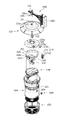
도 1 - 본 발명에 따른 레이저빔을 이용한 해충 포집장치를 도시한 분리 사시도.
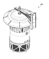
도 2 - 도 1의 결합된 상태를 도시한 사시도.
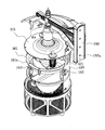
도 3 - 도 2의 일부 절개 사시도.
도 4 - 도 2의 단면도.
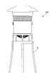
도 5 - 본 발명의 사용상태 참고도.1 is an exploded perspective view showing a pest collecting apparatus using a laser beam according to the present invention;
FIG. 2 is a perspective view showing the combined state of FIG. 1; FIG.
Fig. 3 is a partially cutaway perspective view of Fig. 2; Fig.
FIG. 4 is a sectional view of FIG. 2; FIG.
5 is a use state view of the present invention.
상기한 목적 및 효과를 달성하기 위한 본 발명을 바람직한 실시예를 통해 더욱 상세히 설명하면 다음과 같다.
The above and other objects, features, and advantages of the present invention will become more apparent from the following detailed description of the present invention when taken in conjunction with the accompanying drawings.
본 발명에 따른 레이저빔을 이용한 해충 포집장치(100)는, 현수 가능토록 상부에 걸이구(111)가 형성되고 저부에 해충유인등(112)이 결합되는 전등갓(110); 상기 전등갓(110)의 하단에 결합되고, 상부 외주면에 유인공(121)이 다수 형성된 원통형의 하우징(120); 상기 유인공(121)의 하부에 위치하되, 하우징(120)의 내부에 고정되는 흡입팬(130); 상기 흡입팬(130)을 구동하기 위한 제1 모터(131); 상기 제1 모터(131)의 하부에 위치하되, 하우징(120)의 내부에 형성되는 개폐수단(140); 상기 하우징(120)의 하단에 결합되는 포집수단(150);을 포함하도록 구성된 해충 포집장치에 있어서, 상기 흡입팬(130)이 위치한 하우징(120) 내부의 안내돌기(122)에 걸리도록 상부에 플랜지(161)가 형성된 회전체(160)를 더 구성하되; 상기 플랜지(161)에는 다수의 투사공(161a)이 형성되고, 상기 투사공(161a)의 저부에는 레이저빔을 투사하기 위한 발광수단(162)이 형성되며, 상기 회전체(160)의 하단은 제1 모터(131)의 하부에 형성된 제2 모터(132)의 축(132a)에 결합되어 상기 제2 모터(132)의 구동에 의해 회전체(160)가 일정속도로 회전하도록 구성된다.
A pest-inspecting apparatus (100) using a laser beam according to the present invention includes: a lamp shade (110) having a hanging hole (111) formed at an upper portion thereof so as to be suspended and coupled with a pest inducing lamp (112) at a bottom thereof; A
여기서 전등갓(110); 하우징(120); 흡입팬(130); 제1 모터(131); 개폐수단(140); 포집수단(150);은 해충 포집장치를 구성하기 위한 통상의 기술적 구성에 해당하므로 이에 대한 자세한 설명을 생략하기로 한다.The
나아가 상기 전등갓(110)의 해충유인등(112)은 형광램프나 발광 다이오드 등 다양한 형태로 구성이 가능하고, 상기 해충유인등(112)은 특정 종류의 해충이 선호하는 파장의 자외선을 집중적으로 조사하거나 또는 다양한 종류의 해충을 포획하기 위해 둘 이상 형성되고, 도면에 도시된 바와 같이 수직방향이나 가로방향으로 다수 형성될 수도 있음은 당연하다.Further, the
나아가 상기 하우징(120)의 유인공(121)은 도면에 도시된 바와 같이, 일자형의 통공으로 구성할 수도 있으며, 이외의 원형, 사각형 등의 다각형으로 구성할 수도 있고, 또 사용자의 필요에 따라 유인공(121)을 2열 이상으로 탈부착하거나 전체를 하나의 구멍으로 형성할 수도 있다.Further, as shown in the figure, the
나아가 상기 개폐수단(140)은 등록특허 제10-0894397호에 게시된 기술을 인용하여 전원과의 연결 없이 풍력과 무게중심을 이용하여 자동으로 개폐되도록 구성함이 바람직하다.Furthermore, the opening /
나아가 상기 전등갓(110), 하우징(120), 개폐수단(140), 포집수단(150)은 후크 결합구조로 분리 및 조립이 가능토록 구성됨이 바람직하다.Furthermore, it is preferable that the
그리고 [도 4]에 도시된 바와 같이, 상기 흡입팬(130)이 위치한 하우징(120) 내부의 안내돌기(122)에 걸리도록 상부에 플랜지(161)가 형성된 회전체(160)가 더 구성된다.4, the rotating
물론 상기 안내돌기(122)의 상면에는 회전체(160)의 회전이 자유롭게 이루어지도록 볼베어링의 구조를 가지도록 구성할 수도 있음은 당연하다 할 것이다.Needless to say, the
나아가 상기 회전체(160)는 제2 모터(132)의 구동에 의해 일정속도로 회전되어 지는데, 이때 상기 회전체(160)의 하단은 제2 모터(132)의 축(132a)에 결합되도록 연장될 수도 있다.The lower end of the rotating
물론 상기 제2 모터(132)의 축(132)에 결합되어 회전되는 회전수단을 부가하되, 상기 회전수단의 끝단이 회전체(160)의 하단에 연결되도록 하여 상기 회전체(160)의 회전을 유도할 수도 있음은 당연하다.Of course, a rotating means coupled to the
나아가 상기 회전체(160)의 플랜지(161)에는 다수의 투사공(161a)이 형성되고, 상기 투사공(161a)의 저부에는 레이저빔을 투사하기 위한 발광수단(162)이 형성된다.A plurality of
그리고 상기 레이저는 500㎽ 이상의 고출력의 레이저 다이오드 형태로 제조가 되고 있는데, 이런 레이저의 강한 출력을 이용하는 경우 날아다니는 파리, 모기와 같은 해충에 지름 1㎜ 이하로 집광하여 조준 발사할 경우 죽이거나 치명적 상처를 줄 수 있게 되므로, 상기 발광수단(162)의 레이저 광원으로는 고출력 레이저 다이오드가 사용됨이 바람직하다.The laser is manufactured in the form of a laser diode with a high output of 500 mW or more. When the strong output of the laser is used, when the laser is condensed at a diameter of 1 mm or less to a flying insect such as a fly or a mosquito, It is preferable that a high power laser diode is used as the laser light source of the light emitting means 162. [
물론 상기 레이저빔의 투사로 인해 발광수단(162)의 상부에 위치한 전등갓(110)이나 보조갓(115)이 손상되는 것을 방지하기 위해 상기 전등갓(110)과 보조갓(115)은 금속재질로 구성됨이 바람직하다.Of course, the
나아가 상기 레이저빔을 대체하여 해충에게 전기적 충격을 가할 수 있는 도전체를 구성하되, 상기 도전체를 용도에 따라 탈부착 가능토록 구성할 수도 있음은 당연하다.
Furthermore, it is a matter of course that a conductor capable of replacing the laser beam and applying an electric shock to the insect pest can be constructed, and the conductor can be configured to be detachable depending on the use.
한편, 하우징(120)의 유인공(121)의 상부에는 단턱(123)이 형성되어 지되, 상기 단턱(123)에는 중심에 해충유인등(112)의 결합을 위한 제1 통공(115a)과 테두리부에 제1 해충유인수단(170)의 결합을 위한 제2 통공(115b)이 형성된 보조갓(115)이 안착되도록 구성된다.A
즉 상기 보조갓(115)의 중심에 형성된 제1 통공(115a)에는 하부로 해충유인등(112)이 노출되고, 테두리부에 형성된 제2 통공(115b)에는 다수의 제1 해충유인수단(170)이 하부로 노출·결합된다.That is, a
그리고 상기 제1 해충유인수단(170)은 수직방향으로 다수의 노출공(171a)이 형성된 몸체(171)와, 제2 통공(115b)을 관통하여 몸체(171)의 상부에 결합되는 캡(172)으로 구성된다.The first
나아가 상기 몸체(171)에는 해충을 유인하기 위한 유인물질이 수납되는데, 이때 상기 유인물질의 향은 노출공(171a)을 통해 외부로 노출되므로 해충을 유인할 수 있는 것이다.
In addition, the
한편, 하우징(120)의 중간부에는 다수의 결합공(124)이 형성되어 지되, 상기 결합공(124)에는 페로몬액이 충진된 제2 해충유인수단(180)이 끼움·결합되도록 구성된다.A plurality of
즉 도면에 도시된 바와 같이, 상기 결합공(124)을 하우징(120)의 중간부에 둘 또는 그 이상 형성하되, 상기 결합공(124)에 페로몬액이 충진된 제2 해충유인수단(180)을 끼움·결합함으로써 해충을 유인하여 포획할 수 있는 것이다.That is, as shown in the drawing, two or more of the
물론 상기 제1,2 해충유인수단(170,180)에는 해충을 종류별로 유인가능토록 그 성분을 달리하여 구성함은 당연하다 할 것이다.
Of course, it is natural that the first and second pest inducing means 170 and 180 are constituted by different components so that the pest can be attracted to each kind.
한편, 걸이구(111)의 걸이공(111a)에 대응하는 끼움공(191a)이 구비된 결합구(191)가 일단부에 형성되고, 타단부에는 벽면에 걸기 위한 브라켓(192)이 형성된 걸이수단(190);을 더 형성하도록 구성된다.A
즉 상기 걸이구(111)를 통해 특정 장소에 해충 포집장치(100)를 걸어두거나 또는 걸이수단(190)이 고정핀(195)에 의해 고정되도록 함으로써 벽면에 해충 포집장치(100)를 설치할 수 있는 것이다.That is, the
이를 위해 상기 걸이공(111a)과 끼움공(191a)에는 고정핀(195)이 결합되고, 상기 브라켓(192)에는 다수의 체결공(192a)이 형성된다.To this end, a
나아가 [도 5]에 도시된 바와 같이, 해충 포집장치(100)를 올려놓은 상태에서 사용가능토록 삼발이 받침대(A)를 더 구성할 수도 있다.
Furthermore, as shown in FIG. 5, the tripod cradle A may be further configured so that it can be used in a state in which the
상술한 바와 같이 본 발명은 비록 한정된 실시예에 의해 설명되었으나, 본 발명은 이것에 한정되지 않으며 본 발명이 속하는 기술분야에서 통상의 지식을 가진 자에 의해 본 발명의 기술사상과 아래에 기재될 특허청구범위의 균등범위 내에서 다양한 수정 및 변형이 가능하다 할 것이다.
Although the present invention has been described with reference to the exemplary embodiments, it is to be understood that the present invention is not limited to the disclosed exemplary embodiments, and that various changes and modifications will be apparent to those skilled in the art. Various modifications and variations may be made without departing from the scope of the appended claims.
* 도면의 주요부분에 대한 부호의 설명 *
100: 해충 포집장치
110: 전등갓 111: 걸이구
111a: 걸이공 112: 해충유인등
115: 보조갓 115a: 제1 통공
115b: 제2 통공 120: 하우징
121: 유인공 122: 안내돌기
123: 단턱 124: 결합공
130: 흡입팬 131: 제1 모터
132: 제2 모터 131a,132a: 축
140: 개폐수단 150: 포집수단
160: 회전체 161: 플랜지
161a: 투사공 162: 발광수단
170: 제1 해충유인수단 171: 몸체
172: 캡 180: 제2 해충유인수단
190: 걸이수단 191: 결합구
192: 브라켓 195: 고정핀
A: 삼발이 받침대Description of the Related Art [0002]
100: Pest collecting device
110: lamp shade 111: hanger
111a: Hook ball 112: Insect pest, etc.
115:
115b: second through hole 120: housing
121: Artificial needle 122: Guide projection
123: step 124:
130: Suction fan 131: First motor
132:
140: opening / closing means 150: collection means
160: rotating body 161: flange
161a: projection hole 162: light emitting means
170: First pest attraction means 171: Body
172: Cap 180: the second pest inducing means
190: means for hooking 191:
192: Bracket 195: Fixing pin
A: Three-legged pedestal
Claims (5)
상기 흡입팬(130)이 위치한 하우징(120) 내부의 안내돌기(122)에 걸리도록 상부에 플랜지(161)가 형성된 회전체(160)를 더 구성하되; 상기 플랜지(161)에는 다수의 투사공(161a)이 형성되고, 상기 투사공(161a)의 저부에는 레이저빔을 투사하기 위한 발광수단(162)이 형성되며, 상기 회전체(160)의 하단은 제1 모터(131)의 하부에 형성된 제2 모터(132)의 축(132a)에 결합되어 상기 제2 모터(132)의 구동에 의해 회전체(160)가 일정속도로 회전하도록 구성되는 것을 특징으로 하는 레이저빔을 이용한 해충 포집장치.
A lamp shade 110 in which a hook 111 is formed at an upper portion so as to be able to hang and a pest induction lamp 112 is coupled to a bottom portion; A cylindrical housing 120 coupled to a lower end of the lamp shade 110 and having a plurality of oil holes 121 formed on an upper outer circumferential surface thereof; A suction fan 130 positioned below the fluid guide 121 and fixed to the inside of the housing 120; A first motor 131 for driving the suction fan 130; Opening and closing means 140 located at a lower portion of the first motor 131 and formed inside the housing 120; And a collecting means (150) coupled to a lower end of the housing (120), wherein the pest collecting device
A rotating body 160 having a flange 161 formed at an upper portion thereof so as to be caught by the guide protrusion 122 inside the housing 120 in which the suction fan 130 is located; A plurality of projecting holes 161a are formed in the flange 161 and a light emitting means 162 for projecting a laser beam is formed on the bottom of the projection hole 161a. And is configured to be coupled to a shaft 132a of a second motor 132 formed at a lower portion of the first motor 131 so that the rotating body 160 rotates at a constant speed by driving the second motor 132 The insect trapping device using the laser beam.
상기 발광수단(162)의 레이저 광원으로는 고출력 레이저 다이오드가 사용되도록 구성되는 것을 특징으로 하는 레이저빔을 이용한 해충 포집장치.
The method of claim 1,
And a high power laser diode is used as the laser light source of the light emitting means (162).
상기 유인공(121)의 상부에는 단턱(123)이 형성되어 지되, 상기 단턱(123)에는 중심에 해충유인등(112)의 결합을 위한 제1 통공(115a)과 테두리부에 제1 해충유인수단(170)의 결합을 위한 제2 통공(115b)이 형성된 보조갓(115)이 안착되고; 상기 제1 해충유인수단(170)은 수직방향으로 다수의 노출공(171a)이 형성된 몸체(171)와 제2 통공(115b)을 관통하여 몸체(171)의 상부에 결합되는 캡(172)으로 구성되는 것을 특징으로 하는 레이저빔을 이용한 해충 포집장치.
The method of claim 1,
A step 123 is formed in the upper part of the fluid guide 121. The step 123 includes a first through hole 115a for coupling the insect insect 112 and a first insect insect An auxiliary cap (115) with a second through hole (115b) for engagement of the means (170) is seated; The first insect attracting means 170 includes a body 171 formed with a plurality of exposure holes 171a in the vertical direction and a cap 172 coupled to the upper portion of the body 171 through the second through hole 115b And a pest control device for controlling the pest control device.
상기 하우징(120)의 중간부에는 다수의 결합공(124)이 형성되어 지되, 상기 결합공(124)에는 페로몬액이 충진된 제2 해충유인수단(180)이 끼움·결합되도록 구성되는 것을 특징으로 하는 레이저빔을 이용한 해충 포집장치.
The method of claim 1,
A plurality of engagement holes 124 are formed in the middle portion of the housing 120. A second insect attracting means 180 filled with a pheromone solution is inserted into the engagement holes 124 The insect trapping device using the laser beam.
상기 걸이구(111)의 걸이공(111a)에 대응하는 끼움공(191a)이 구비된 결합구(191)가 일단부에 형성되고, 타단부에는 벽면에 걸기 위한 브라켓(192)이 형성된 걸이수단(190);이 더 형성되어 지되, 상기 걸이공(111a)과 끼움공(191a)에는 고정핀(195)이 결합되어 걸이수단(190)이 고정되도록 구성되는 것을 특징으로 하는 레이저빔을 이용한 해충 포집장치.5. The method according to any one of claims 1 to 4,
A hooking part 191 having a fitting hole 191a corresponding to the hooking hole 111a of the hooking part 111 is formed at one end and a hooking part 192 having a bracket 192 for hooking to a wall surface is formed at the other end part. And a fixing pin 195 is coupled to the hooking hole 111a and the fitting hole 191a so that the hooking unit 190 is fixed. Collection device.
Priority Applications (1)
| Application Number | Priority Date | Filing Date | Title |
|---|---|---|---|
| KR1020120059587A KR101424238B1 (en) | 2012-06-04 | 2012-06-04 | Harmful insect grasping device using laser beam |
Applications Claiming Priority (1)
| Application Number | Priority Date | Filing Date | Title |
|---|---|---|---|
| KR1020120059587A KR101424238B1 (en) | 2012-06-04 | 2012-06-04 | Harmful insect grasping device using laser beam |
Publications (2)
| Publication Number | Publication Date |
|---|---|
| KR20140011491A true KR20140011491A (en) | 2014-01-29 |
| KR101424238B1 KR101424238B1 (en) | 2014-07-30 |
Family
ID=50143644
Family Applications (1)
| Application Number | Title | Priority Date | Filing Date |
|---|---|---|---|
| KR1020120059587A Expired - Fee Related KR101424238B1 (en) | 2012-06-04 | 2012-06-04 | Harmful insect grasping device using laser beam |
Country Status (1)
| Country | Link |
|---|---|
| KR (1) | KR101424238B1 (en) |
Cited By (16)
| Publication number | Priority date | Publication date | Assignee | Title |
|---|---|---|---|---|
| CN105309406A (en) * | 2015-10-21 | 2016-02-10 | 中国水稻研究所 | Capture and disposal device for field insects |
| RU2578796C1 (en) * | 2015-02-06 | 2016-03-27 | Алексей Сергеевич Познышев | Device for destruction of blood-sucking insects |
| RU2578795C1 (en) * | 2015-02-06 | 2016-03-27 | Алексей Сергеевич Познышев | Device for destruction of blood-sucking insects |
| WO2016126172A1 (en) * | 2015-02-06 | 2016-08-11 | Алексей Сергеевич ПОЗНЫШЕВ | Device for exterminating blood-sucking insects (variants) |
| CN105941368A (en) * | 2016-07-07 | 2016-09-21 | 厦门唯科健康科技有限公司 | Insect catching box and insect catching machine with same |
| CN106993598A (en) * | 2017-05-25 | 2017-08-01 | 李良杰 | Laser mosquito killer |
| KR101854414B1 (en) * | 2016-12-14 | 2018-05-03 | 주식회사 이레그린 | vermin trap by attractant |
| KR101896037B1 (en) * | 2018-04-11 | 2018-09-07 | (주)씨프로 | Cctv surveillance camera system with anti-spider erasure function |
| WO2018182265A1 (en) * | 2017-03-29 | 2018-10-04 | 서울바이오시스주식회사 | Illumination device |
| CN111225560A (en) * | 2017-08-18 | 2020-06-02 | 首尔伟傲世有限公司 | insect trap |
| CN111328787A (en) * | 2020-04-01 | 2020-06-26 | 苏志峰 | A lure worm device of killing for pest control |
| CN113575540A (en) * | 2021-07-26 | 2021-11-02 | 海南盛果科技开发有限公司 | Portable folding type deinsectization lamp |
| KR102402878B1 (en) * | 2021-06-02 | 2022-05-31 | (주)다목에코텍 | A noxious insect luring and capturing device |
| KR20230020093A (en) * | 2021-08-03 | 2023-02-10 | (주)다목에코텍 | A noxious insect luring and capturing device attached to a pillar |
| KR102516540B1 (en) * | 2021-12-02 | 2023-03-31 | 임승용 | Electronic insect repellent apparatus |
| CN120959215A (en) * | 2025-09-28 | 2025-11-18 | 广东国志激光技术有限公司 | A pest control device based on laser-induced killing |
Families Citing this family (1)
| Publication number | Priority date | Publication date | Assignee | Title |
|---|---|---|---|---|
| KR102574929B1 (en) * | 2018-01-04 | 2023-09-06 | 서울바이오시스 주식회사 | Insect trap |
Family Cites Families (4)
| Publication number | Priority date | Publication date | Assignee | Title |
|---|---|---|---|---|
| KR20000005372U (en) * | 1998-08-28 | 2000-03-25 | 김동균 | Mosquito trapping device for outdoor and indoor light |
| KR100603987B1 (en) | 2006-02-02 | 2006-07-25 | 주식회사 현진기업 | Pest Induction Collector using LED and Fiber |
| KR200421269Y1 (en) | 2006-04-26 | 2006-07-10 | 송종명 | Pest collecting device |
| KR100945366B1 (en) | 2009-01-08 | 2010-03-08 | 이준길 | Green a noxious insect control device |
-
2012
- 2012-06-04 KR KR1020120059587A patent/KR101424238B1/en not_active Expired - Fee Related
Cited By (18)
| Publication number | Priority date | Publication date | Assignee | Title |
|---|---|---|---|---|
| RU2578796C1 (en) * | 2015-02-06 | 2016-03-27 | Алексей Сергеевич Познышев | Device for destruction of blood-sucking insects |
| RU2578795C1 (en) * | 2015-02-06 | 2016-03-27 | Алексей Сергеевич Познышев | Device for destruction of blood-sucking insects |
| WO2016126172A1 (en) * | 2015-02-06 | 2016-08-11 | Алексей Сергеевич ПОЗНЫШЕВ | Device for exterminating blood-sucking insects (variants) |
| CN105309406A (en) * | 2015-10-21 | 2016-02-10 | 中国水稻研究所 | Capture and disposal device for field insects |
| CN105941368A (en) * | 2016-07-07 | 2016-09-21 | 厦门唯科健康科技有限公司 | Insect catching box and insect catching machine with same |
| KR101854414B1 (en) * | 2016-12-14 | 2018-05-03 | 주식회사 이레그린 | vermin trap by attractant |
| WO2018182265A1 (en) * | 2017-03-29 | 2018-10-04 | 서울바이오시스주식회사 | Illumination device |
| CN106993598A (en) * | 2017-05-25 | 2017-08-01 | 李良杰 | Laser mosquito killer |
| CN111225560A (en) * | 2017-08-18 | 2020-06-02 | 首尔伟傲世有限公司 | insect trap |
| KR101896037B1 (en) * | 2018-04-11 | 2018-09-07 | (주)씨프로 | Cctv surveillance camera system with anti-spider erasure function |
| WO2019198888A1 (en) * | 2018-04-11 | 2019-10-17 | (주)씨프로 | Cctv surveillance camera system with spider elimination function |
| CN111328787A (en) * | 2020-04-01 | 2020-06-26 | 苏志峰 | A lure worm device of killing for pest control |
| CN111328787B (en) * | 2020-04-01 | 2022-05-03 | 苏志峰 | A lure worm device of killing for pest control |
| KR102402878B1 (en) * | 2021-06-02 | 2022-05-31 | (주)다목에코텍 | A noxious insect luring and capturing device |
| CN113575540A (en) * | 2021-07-26 | 2021-11-02 | 海南盛果科技开发有限公司 | Portable folding type deinsectization lamp |
| KR20230020093A (en) * | 2021-08-03 | 2023-02-10 | (주)다목에코텍 | A noxious insect luring and capturing device attached to a pillar |
| KR102516540B1 (en) * | 2021-12-02 | 2023-03-31 | 임승용 | Electronic insect repellent apparatus |
| CN120959215A (en) * | 2025-09-28 | 2025-11-18 | 广东国志激光技术有限公司 | A pest control device based on laser-induced killing |
Also Published As
| Publication number | Publication date |
|---|---|
| KR101424238B1 (en) | 2014-07-30 |
Similar Documents
| Publication | Publication Date | Title |
|---|---|---|
| KR101424238B1 (en) | Harmful insect grasping device using laser beam | |
| JP2004254523A (en) | Capturing tool for attracting insect pest | |
| US6502347B1 (en) | Lighted insect trap | |
| US20060218851A1 (en) | Insect trap device | |
| KR100945366B1 (en) | Green a noxious insect control device | |
| KR101545083B1 (en) | Potable electric kill insecticide device | |
| KR101232956B1 (en) | Harmful insect grasping equipment | |
| KR100632277B1 (en) | Reptile | |
| CN209898056U (en) | Insecticidal lamp fan | |
| KR20130115963A (en) | Apparatus for trapping flying incert and interception | |
| KR20090005532U (en) | Pest trap | |
| CN213840698U (en) | Indoor illuminating lamp with deinsectization function | |
| JP2000253793A (en) | Mosquito / Fly Attractor | |
| KR200467175Y1 (en) | Insect exterminating apparatus using by electric fan | |
| KR200442596Y1 (en) | Pest capture device equipped with attractant | |
| CN2141963Y (en) | Cantilever Mosquito Trap | |
| KR101393105B1 (en) | Bug capturing device of air drop type | |
| JP2005117970A (en) | Insect pest trap | |
| WO2000059300A1 (en) | Insect trap | |
| KR101041708B1 (en) | Pest trapping device | |
| KR102049286B1 (en) | Harmful insect grasping equipment | |
| KR200339661Y1 (en) | A catching equipment to insect | |
| KR100632278B1 (en) | Reptile | |
| KR20050090276A (en) | Apparatus to catch harmful insects | |
| KR200332379Y1 (en) | A winged insect capture apparatus |
Legal Events
| Date | Code | Title | Description |
|---|---|---|---|
| A201 | Request for examination | ||
| PA0109 | Patent application |
St.27 status event code: A-0-1-A10-A12-nap-PA0109 |
|
| PA0201 | Request for examination |
St.27 status event code: A-1-2-D10-D11-exm-PA0201 |
|
| P11-X000 | Amendment of application requested |
St.27 status event code: A-2-2-P10-P11-nap-X000 |
|
| P13-X000 | Application amended |
St.27 status event code: A-2-2-P10-P13-nap-X000 |
|
| P11-X000 | Amendment of application requested |
St.27 status event code: A-2-2-P10-P11-nap-X000 |
|
| P11-X000 | Amendment of application requested |
St.27 status event code: A-2-2-P10-P11-nap-X000 |
|
| P11-X000 | Amendment of application requested |
St.27 status event code: A-2-2-P10-P11-nap-X000 |
|
| P13-X000 | Application amended |
St.27 status event code: A-2-2-P10-P13-nap-X000 |
|
| PE0801 | Dismissal of amendment |
St.27 status event code: A-2-2-P10-P12-nap-PE0801 |
|
| PE0801 | Dismissal of amendment |
St.27 status event code: A-2-2-P10-P12-nap-PE0801 |
|
| D13-X000 | Search requested |
St.27 status event code: A-1-2-D10-D13-srh-X000 |
|
| D14-X000 | Search report completed |
St.27 status event code: A-1-2-D10-D14-srh-X000 |
|
| E902 | Notification of reason for refusal | ||
| PE0902 | Notice of grounds for rejection |
St.27 status event code: A-1-2-D10-D21-exm-PE0902 |
|
| P11-X000 | Amendment of application requested |
St.27 status event code: A-2-2-P10-P11-nap-X000 |
|
| P13-X000 | Application amended |
St.27 status event code: A-2-2-P10-P13-nap-X000 |
|
| P11-X000 | Amendment of application requested |
St.27 status event code: A-2-2-P10-P11-nap-X000 |
|
| P13-X000 | Application amended |
St.27 status event code: A-2-2-P10-P13-nap-X000 |
|
| P22-X000 | Classification modified |
St.27 status event code: A-2-2-P10-P22-nap-X000 |
|
| P22-X000 | Classification modified |
St.27 status event code: A-2-2-P10-P22-nap-X000 |
|
| PG1501 | Laying open of application |
St.27 status event code: A-1-1-Q10-Q12-nap-PG1501 |
|
| E701 | Decision to grant or registration of patent right | ||
| P22-X000 | Classification modified |
St.27 status event code: A-2-2-P10-P22-nap-X000 |
|
| PE0701 | Decision of registration |
St.27 status event code: A-1-2-D10-D22-exm-PE0701 |
|
| GRNT | Written decision to grant | ||
| PR0701 | Registration of establishment |
St.27 status event code: A-2-4-F10-F11-exm-PR0701 |
|
| PR1002 | Payment of registration fee |
St.27 status event code: A-2-2-U10-U11-oth-PR1002 Fee payment year number: 1 |
|
| PG1601 | Publication of registration |
St.27 status event code: A-4-4-Q10-Q13-nap-PG1601 |
|
| PN2301 | Change of applicant |
St.27 status event code: A-5-5-R10-R13-asn-PN2301 St.27 status event code: A-5-5-R10-R11-asn-PN2301 |
|
| P14-X000 | Amendment of ip right document requested |
St.27 status event code: A-5-5-P10-P14-nap-X000 |
|
| P16-X000 | Ip right document amended |
St.27 status event code: A-5-5-P10-P16-nap-X000 |
|
| Q16-X000 | A copy of ip right certificate issued |
St.27 status event code: A-4-4-Q10-Q16-nap-X000 |
|
| R18-X000 | Changes to party contact information recorded |
St.27 status event code: A-5-5-R10-R18-oth-X000 |
|
| PN2301 | Change of applicant |
St.27 status event code: A-5-5-R10-R13-asn-PN2301 St.27 status event code: A-5-5-R10-R11-asn-PN2301 |
|
| R17-X000 | Change to representative recorded |
St.27 status event code: A-5-5-R10-R17-oth-X000 |
|
| R18-X000 | Changes to party contact information recorded |
St.27 status event code: A-5-5-R10-R18-oth-X000 |
|
| P22-X000 | Classification modified |
St.27 status event code: A-4-4-P10-P22-nap-X000 |
|
| FPAY | Annual fee payment |
Payment date: 20170724 Year of fee payment: 4 |
|
| PR1001 | Payment of annual fee |
St.27 status event code: A-4-4-U10-U11-oth-PR1001 Fee payment year number: 4 |
|
| P22-X000 | Classification modified |
St.27 status event code: A-4-4-P10-P22-nap-X000 |
|
| FPAY | Annual fee payment |
Payment date: 20180723 Year of fee payment: 5 |
|
| PR1001 | Payment of annual fee |
St.27 status event code: A-4-4-U10-U11-oth-PR1001 Fee payment year number: 5 |
|
| FPAY | Annual fee payment |
Payment date: 20190722 Year of fee payment: 6 |
|
| PR1001 | Payment of annual fee |
St.27 status event code: A-4-4-U10-U11-oth-PR1001 Fee payment year number: 6 |
|
| PR1001 | Payment of annual fee |
St.27 status event code: A-4-4-U10-U11-oth-PR1001 Fee payment year number: 7 |
|
| PR1001 | Payment of annual fee |
St.27 status event code: A-4-4-U10-U11-oth-PR1001 Fee payment year number: 8 |
|
| PR1001 | Payment of annual fee |
St.27 status event code: A-4-4-U10-U11-oth-PR1001 Fee payment year number: 9 |
|
| PR1001 | Payment of annual fee |
St.27 status event code: A-4-4-U10-U11-oth-PR1001 Fee payment year number: 10 |
|
| PC1903 | Unpaid annual fee |
St.27 status event code: A-4-4-U10-U13-oth-PC1903 Not in force date: 20240723 Payment event data comment text: Termination Category : DEFAULT_OF_REGISTRATION_FEE |
|
| PC1903 | Unpaid annual fee |
St.27 status event code: N-4-6-H10-H13-oth-PC1903 Ip right cessation event data comment text: Termination Category : DEFAULT_OF_REGISTRATION_FEE Not in force date: 20240723 |