KR20140001756U - A permeable block and a rainwater pipe permeable structure - Google Patents
A permeable block and a rainwater pipe permeable structure Download PDFInfo
- Publication number
- KR20140001756U KR20140001756U KR2020120008343U KR20120008343U KR20140001756U KR 20140001756 U KR20140001756 U KR 20140001756U KR 2020120008343 U KR2020120008343 U KR 2020120008343U KR 20120008343 U KR20120008343 U KR 20120008343U KR 20140001756 U KR20140001756 U KR 20140001756U
- Authority
- KR
- South Korea
- Prior art keywords
- pipe
- block
- volcanic stone
- coupling groove
- rainwater
- Prior art date
Links
Images


Classifications
-
- E—FIXED CONSTRUCTIONS
- E01—CONSTRUCTION OF ROADS, RAILWAYS, OR BRIDGES
- E01C—CONSTRUCTION OF, OR SURFACES FOR, ROADS, SPORTS GROUNDS, OR THE LIKE; MACHINES OR AUXILIARY TOOLS FOR CONSTRUCTION OR REPAIR
- E01C11/00—Details of pavings
- E01C11/22—Gutters; Kerbs ; Surface drainage of streets, roads or like traffic areas
- E01C11/224—Surface drainage of streets
- E01C11/225—Paving specially adapted for through-the-surfacing drainage, e.g. perforated, porous; Preformed paving elements comprising, or adapted to form, passageways for carrying off drainage
-
- E—FIXED CONSTRUCTIONS
- E01—CONSTRUCTION OF ROADS, RAILWAYS, OR BRIDGES
- E01C—CONSTRUCTION OF, OR SURFACES FOR, ROADS, SPORTS GROUNDS, OR THE LIKE; MACHINES OR AUXILIARY TOOLS FOR CONSTRUCTION OR REPAIR
- E01C5/00—Pavings made of prefabricated single units
- E01C5/003—Pavings made of prefabricated single units characterised by material or composition used for beds or joints; characterised by the way of laying
-
- E—FIXED CONSTRUCTIONS
- E01—CONSTRUCTION OF ROADS, RAILWAYS, OR BRIDGES
- E01C—CONSTRUCTION OF, OR SURFACES FOR, ROADS, SPORTS GROUNDS, OR THE LIKE; MACHINES OR AUXILIARY TOOLS FOR CONSTRUCTION OR REPAIR
- E01C5/00—Pavings made of prefabricated single units
- E01C5/22—Pavings made of prefabricated single units made of units composed of a mixture of materials covered by two or more of groups E01C5/008, E01C5/02 - E01C5/20 except embedded reinforcing materials
-
- E—FIXED CONSTRUCTIONS
- E03—WATER SUPPLY; SEWERAGE
- E03F—SEWERS; CESSPOOLS
- E03F5/00—Sewerage structures
- E03F5/04—Gullies inlets, road sinks, floor drains with or without odour seals or sediment traps
- E03F5/0401—Gullies for use in roads or pavements
-
- E—FIXED CONSTRUCTIONS
- E01—CONSTRUCTION OF ROADS, RAILWAYS, OR BRIDGES
- E01C—CONSTRUCTION OF, OR SURFACES FOR, ROADS, SPORTS GROUNDS, OR THE LIKE; MACHINES OR AUXILIARY TOOLS FOR CONSTRUCTION OR REPAIR
- E01C2201/00—Paving elements
- E01C2201/20—Drainage details
Abstract
본 고안은 투수 블록 및 우수관 투수 구조에 관한 것으로서, 더욱 상세하게는 화산석을 이용하여 인도나 도로의 빗물에 대한 배수 효과를 극대화하고 이물질이 관로에 유입되지 않도록 한 투수 블록 및 우수관 투수 구조에 관한 것이다.
이를 위해, 상부에는 소정의 깊이를 갖는 결합홈이 형성된 블록;상기 블록의 결합홈으로부터 블록의 저면을 향해 형성된 복수의 배수유로;상기 결합홈에 타설되어 양생을 거쳐 결합된 화산석:을 포함하여 구성된 투수 블록을 제공한다.The present invention relates to a permeation block and stormwater permeation structure, and more particularly, to a permeation block and stormwater permeation structure using volcanic stones to maximize drainage effect on sidewalks or road rainwater and to prevent foreign substances from entering the pipeline. .
To this end, the upper block is formed with a coupling groove having a predetermined depth; A plurality of drainage flow path formed toward the bottom surface of the block from the coupling groove of the block; Volcanic stone is poured into the coupling groove and bonded through curing: Provide a pitcher block.
Description
본 고안은 투수 블록 및 우수관 투수 구조에 관한 것으로서, 더욱 상세하게는 빗물에 대한 배수 효과를 극대화한 투수 블록 및 우수관 투수 구조에 관한 것이다.The present invention relates to a permeation block and storm pipe permeation structure, and more particularly to a permeation block and storm pipe permeability structure to maximize the drainage effect on rainwater.
최근 도시화의 가속화로 인해 도로와 지표면이 아스팔트와 콘크리트로 포장되는 면적이 많이 증가하고 있다.Recently, due to the acceleration of urbanization, the area where roads and the surface are paved with asphalt and concrete is increasing.
이러한 도로의 증가와 더불어 사람의 보행을 위한 인도 역시 증가되고 있으며, 상기 인도는 주로 보도블록을 통해 이루어진다.With the increase of these roads, the sidewalk for human walking is also increasing, which is mainly through sidewalk blocks.
보도블록은 골재, 쇄석 등의 골재와 모래 및 시멘트를 일정 비율로 혼합한 뒤 소정의 형상을 갖는 형틀에서 찍어내어 경화시켜 제조된다.The sidewalk block is manufactured by mixing aggregates such as aggregates, crushed stone, sand and cement in a predetermined ratio, and then dipping and curing in a mold having a predetermined shape.
상기 보도블록은 지면 위에 모래를 포설한 뒤 그 위에 밀착 고정하게 되므로, 우천시 빗물이 보도블록과 보도블록 사이의 틈새를 통해 극히 적은 양의 우수만이 지면으로 흐르고, 대부분의 우수는 보도블록 위에 고여있게 되는 현상이 발생된다.Since the sidewalk block is to be sand and fixed on the ground after installation, only a small amount of rainwater flows to the ground through the gap between the sidewalk block and the sidewalk block in rainy weather, most rainwater is accumulated on the sidewalk block Phenomenon occurs.
즉, 보도블록은 빗물을 지하로 투수시키는 기능이 약하여, 장마나 집중호우시에 사람의 보행에 상당한 불편을 주는 것이다.In other words, the sidewalk block has a weak function of throwing rainwater underground, which causes considerable inconvenience to human walking during rainy season or heavy rains.
게다가, 집중호우시 빗물이 지하로 투수되는 양이 극히 적으므로, 내리는 빗물이 한꺼번에 하천으로 집중되어 범람 원인이 될 뿐만 아니라, 지하수 고갈로 인해 토양이 사막화되어 결국 쾌적한 삶을 영위하기 위한 자연스런 생태계의 유지가 어려운 문제점이 있다.In addition, the amount of rainwater that is pumped into the basement during heavy rains is extremely low, which causes the rainwater to be concentrated in rivers at once and causes flooding, and the groundwater depletion causes the soil to become deserted, leading to a natural life. There is a problem that is difficult to maintain.
물론, 빗물이 모두 보도블록을 통해서만 흘러가는 것이 아니라, 도로의 양 가장자리에 설치된 우수관을 통해 빗물이 배수됨은 당연하다.Of course, not all rainwater flows through the sidewalk block, but it is natural that rainwater is drained through storm pipes installed at both edges of the road.
이하, 상기 우수관에 대하여 간략하게 살펴보도록 한다.Hereinafter, a brief look at the storm pipe.
우수관은 빗물이 도심으로부터 강으로 흘러가도록 유도하는 역할을 하며, 도로의 가장자리를 따라 시공된다.Storm pipes induce rainwater from the city center to the river and are constructed along the edge of the road.
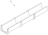
상기 우수관은 사각 수로관, 측구 수로관, 플룸 등의 다양한 형태로 시공이 되며, 이러한 우수관을 시공하기 위한 수로관들의 형태는 도 1a 내지 도 1c에 도시된 바와 같이 직육면체 또는 단면이 'U'자 형태로 제공이 된다.The rain pipe can be constructed in various forms such as a square water pipe, a side channel water pipe, a plume, and the like, and the shape of the water pipes for constructing the water pipe is provided in the form of a 'U' cube or cross section as shown in FIGS. 1A to 1C. Becomes
이때, 직육면체 형태의 사각수로관(10)은 일정 길이를 갖는 복수의 유닛으로 이루어지며, 도로변을 따라 복수의 사각수로관(10)이 연이어 결합됨으로써 우수관에 대한 시공이 이루어지게 된다.At this time, the
이때, 사각 수로관(10)의 상면에는 일정 간격마다, 빗물이 사각 수로관의 내부로 유입될 수 있도록 그레이팅(G)이 설치된다.At this time, the grating (G) is installed on the upper surface of the
그리고, 상면이 개방된 형태의 측구 수로관(20) 및 플룸(30)은 복수의 덮개를 이용해 개방된 부위가 차폐되거나, 일정 간격마다 그레이팅(G)을 이용해 빗물이 측구 수로관(20) 및 플룸(30)의 내부로 유입될 수 있도록 시공된다.In addition, the side
이때, 측구 수로관(20) 및 플룸(30)은 도로 여건에 따라 복수의 덮개 없이 그레이팅(G)을 연이어 설치할 수도 있다.At this time, the
이와 같은 구성에 의해, 빗물은 도로의 가장자리를 따라 그레이팅(G)을 통해 우수관의 내부로 유입된 후, 우수관을 따라 강이나 바다로 흘러가 배수가 이루어지게 된다.By such a configuration, the rainwater flows into the river or the sea along the rain pipe, and then drains through the grating along the edge of the road.
하지만, 상기한 우수관 역시 다음과 같은 문제가 있었다.However, the excellent view also had the following problems.
첫째, 평상적인 우천시에는 크게 상관없으나, 장마나 집중 호우시에 내리는 강수량은 대략 시간당 40mm ~ 80mm에 달해 상기 우수관을 통해 배수량을 소화하지 못함에 따라 빗물이 범람하는 홍수가 발생하게 된다.First, although it does not matter much during normal rainy weather, rainfall during rainy season or heavy rainfall reaches approximately 40 mm to 80 mm per hour, and flooding due to rainwater overflows due to inability to digest the drainage through the storm pipe.
최근들어 지구 온난화의 영향으로 인해, 잦은 집중 호우가 발생하고 있으며, 이로 인해 도심 지역의 피해도 증가하고 있는 실정이다.Recently, due to the effects of global warming, frequent heavy rains have occurred, which is causing damage in urban areas.
즉, 집중호우시 빗물이 지하로 거의 투수되지 못하고 대부분의 빗물이 우수관으로 집중됨에 따라, 홍수를 초래하는 문제가 야기되는 것이다.In other words, when the heavy rain is hardly penetrated into the basement and most of the rain is concentrated in the rain pipe, a problem causing flooding is caused.
둘째, 우수관의 상면은 상기한 바와 같이 도로변을 따라 전면이 개방되거나, 일정 간격마다 개방한 후, 개방된 부위는 그레이팅(G)으로 마감하고 있다.Second, as described above, the upper surface of the rain pipe is open along the roadside, or after opening at regular intervals, the open portion is finished with a grating (G).
이때, 그레이팅(G)을 통해 이물질이나 흙이 유입되어 수로관의 관로 일부를 폐색시키는 문제가 있었다.At this time, the foreign matter or the soil is introduced through the grating (G) has a problem of blocking a part of the water pipe.
특히, 도로에 설치된 그레이팅(G)을 통해 담배꽁초나 쓰레기를 무단 투기함에 따른 피해뿐만 아니라, 잦은 점검과 청소로 인해 관리에 대한 어려움이 발생하였던 것이다.In particular, through the grating (G) installed on the road damage caused by unauthorized dumping of cigarette butts and garbage, as well as frequent inspection and cleaning has caused difficulties in management.
셋째, 보도블록과 마찬가지로 콘크리트 블록 형태의 우수관은 빗물을 지하로 투수시키는 역할이 불가능하므로, 집중호우시 단시간 내에 급격한 강수량의 증가가 일어나 도시형 홍수를 일으키며, 지하수 고갈을 촉진시킬 뿐만 아니라 지표면과 대기의 통기성이 저하되어 지표면의 대기열 흡수 및 지표면으로부터 발생되는 열의 방출이 차단되므로, 대기순환에 악영향을 주고 대기온도를 상승시켜 자연환경을 파괴하는 문제점이 있었다.
Third, like a sidewalk block, a stormwater pipe in the form of a concrete block cannot play a role of pumping rainwater into the ground. Therefore, during heavy rains, rapid precipitation increases, causing urban flooding, and promoting groundwater depletion. Since the air permeability is lowered and the surface absorption of the queue and the release of heat generated from the surface are blocked, there is a problem that adversely affects the atmospheric circulation and increases the atmospheric temperature to destroy the natural environment.
본 고안은 상기한 문제점을 해결하기 위하여 안출된 것으로서, 본 고안의 목적은 화산석을 이용하여 투수(透水) 효과를 극대화함으로써 홍수조절능력을 높이고 지하수 고갈이 억제될 수 있도록 한 투수 블록 및 우수관 구조를 제공하고자 한 것이다.The present invention has been devised to solve the above problems, the object of the present invention is to maximize the permeability (화산 水) effect using volcanic stone to increase the flood control capacity and groundwater depletion can be suppressed groundwater drainage structure It is intended to provide.
본 고안의 다른 목적은 수로관 내부로의 이물질 투입이 방지되도록 수로관의 개방된 부위를 차폐시키되 빗물은 수로관 내부로 투수될 수 있도록 한 우수관 투수 구조를 제공하고자 한 것이다.Another object of the present invention is to provide a rainwater pipe permeable structure to shield the open portion of the waterway pipe to prevent the introduction of foreign matter into the waterway pipe so that rain water can be pumped into the waterway pipe.
본 고안의 또 다른 목적은 투수 블록 및 우수관에 대한 화산석의 결합이 견고하게 이루어질 수 있도록 한 투수 블록 및 우수관 구조를 제공하고자 한 것이다.Another object of the present invention is to provide a permeable block and storm pipe structure that allows the combination of the volcanic stone to the permeable block and storm pipe.
본 고안은 상기한 목적을 달성하기 위하여, 상부에는 소정의 깊이를 갖는 결합홈이 형성된 블록;상기 블록의 결합홈으로부터 블록의 저면을 향해 형성된 배수유로;상기 결합홈에 타설되어 양생을 거쳐 결합된 화산석:을 포함하여 구성된 투수 블록을 제공한다.In order to achieve the above object, the present invention, a block formed with a coupling groove having a predetermined depth in the upper portion; a drainage flow passage formed toward the bottom surface of the block from the coupling groove of the block; Volcanic Stone: Provides a pitcher block consisting of:
이때, 상기 결합홈은 격벽에 의해 복수로 구획되고, 각각의 결합홈마다 화산석이 양생되어 결합된 것이 바람직하다.In this case, the coupling groove is partitioned into a plurality of partitions, it is preferable that the volcanic stone is cured and coupled to each coupling groove.
또한, 상기 격벽에는 이웃하는 결합홈과 통하는 엉김공이 형성되어, 결합홈에서 화산석의 양생시 상기 엉김공을 통해 이웃하는 결합홈의 화산석과 엉기도록 한 것이 바람직하다.In addition, the partition wall is formed with a tangle hole communicating with the neighboring coupling groove, it is preferable to tangled with the volcanic stone of the neighboring coupling groove through the tangle hole during curing of the volcanic stone in the coupling groove.
또한, 상기 결합홈 및 화산석은 다각형 또는 원형인 것이 바람직하다.In addition, the coupling groove and the volcanic stone is preferably polygonal or circular.
본 고안은 상기한 목적을 달성하기 위한 다른 예로써, 강이나 바다를 향해 관로를 형성하는 관체와, 상기 관체의 관로를 향해 빗물이 유입되도록 관체의 상부에 형성된 유입부를 포함하여 구성된 우수관 투수 구조에 있어서, 상기 유입부는 화산석을 포함하는 것을 특징으로 하는 우수관 투수 구조를 제공한다.The present invention is another example for achieving the above object, in the storm pipe permeable structure including a pipe forming a pipe toward the river or the sea, and the inlet formed on the upper portion of the pipe so that rainwater flows toward the pipe of the pipe In the inlet portion provides a storm pipe permeable structure, characterized in that it comprises a volcanic stone.
이때, 상기 유입부는 블록의 관로를 향해 형성된 다각형 또는 원형의 통공과, 상기 통공에 결합된 화산석으로 구성된 것이 바람직하다.At this time, the inlet is preferably composed of a polygonal or circular through hole formed toward the conduit of the block, and the volcanic stone coupled to the through hole.
이때, 상기 유입부는 관체의 관로를 향해 형성된 다각형 또는 원형의 통공과, 상기 통공에 결합된 그레이팅과, 상기 그레이팅의 간격을 메우는 화산석으로 구성된 것이 바람직하다.At this time, the inlet is preferably composed of a polygonal or circular through hole formed toward the conduit of the pipe, the grating coupled to the through hole, the volcanic stone filling the gap of the grating.
또한, 상기 관체는 사각 수로관, 측구 수로관, 플룸관 중 어느 하나인 것이 바람직하다.In addition, the tubular body is preferably any one of a square water pipe, a side opening water pipe, a plume pipe.
본 고안은 상기한 목적을 달성하기 위한 또 다른 예로써, 강이나 바다를 향해 관로를 형성하는 관체와, 상기 관체의 관로를 지나는 빗물이 지하로 배출되도록 형성된 원형 또는 다각형의 배출공과, 상기 배출공에 결합된 화산석을 포함하여 구성된 우수관 투수 구조를 제공한다.The present invention is another example for achieving the above object, the pipe forming the pipeline toward the river or the sea, the discharge hole of the circular or polygonal so that the rain water passing through the pipe of the pipe discharged to the basement, and the discharge hole It provides a storm drain structure composed of volcanic stones coupled to the.
이때, 상기 관체의 측면에는 배출공이 형성되며, 상기 배출공에는 화산석이 결합된 것이 바람직하다.At this time, the discharge hole is formed on the side of the tube, the discharge hole is preferably a volcanic stone combined.
본 고안에 따른 투수 블록 및 우수관 투수 구조는 다음과 같은 효과가 있다.Pitcher block and storm pipe pitcher structure according to the present invention has the following effects.
첫째, 투수 기능이 뛰어난 화산석을 보도 블록에 사용함으로써, 보도 블록을 통한 투수 효과를 극대화할 수 있어 집중 호우에 따른 빗물이 보도 블록에 고이는 일을 방지할 수 있게 된다.First, by using volcanic stone with excellent pitching function in the sidewalk block, it is possible to maximize the permeation effect through the sidewalk block to prevent rainwater from accumulating on the sidewalk block due to the heavy rain.
또한, 우수관으로 빗물이 유입되는 부위에 화산석을 결합함으로써, 집중 호우시 도로나 인도의 빗물을 신속하게 지하 또는 우수관 내로 투수 시킬 수 있게 된다.In addition, by combining the volcanic stone with the rainwater flows into the rainwater pipe, it is possible to quickly permeate the rainwater from the road or sidewalk in the case of heavy rainfall into the underground or rainwater pipe.
이에 따라, 화산석을 포함하는 투수 블록 및 우수관은 투수 능력을 극대화할 수 있으므로, 홍수 발생을 최소화할 수 있는 효과가 있다.Accordingly, the permeable block and storm pipe including volcanic stone can maximize the permeability, thereby minimizing the occurrence of flood.
나아가, 보도블록이나 우수관에 결합된 화산석을 통해 빗물이 지하로 신속하게 스며듦으로써 지하수가 고갈되는 것을 방지할 수 있으며, 지면과 대기 간에 통기성을 높임으로써 자연환경을 향상할 수 있는 효과가 있다.Furthermore, through the volcanic stone combined with the sidewalk block or rainwater pipe, rainwater quickly penetrates into the basement, thereby preventing the groundwater from being depleted, and improving the natural environment by increasing the airflow between the ground and the atmosphere.
둘째, 빗물이 유입될 수 있도록 개방된 우수관의 상면, 또는 그레이팅의 간격 사이에 화산석이 결합됨으로써, 이물질이 우수관 내로 유입되지 않게 된다.Second, the volcanic stone is coupled between the upper surface of the rainwater pipe open to allow rain water, or the interval between the grating, so that foreign matter does not flow into the rainwater pipe.
이에 따라, 우수관의 관로를 깨끗하게 유지할 수 있으므로, 우수 관로를 통한 배수 작용을 높일 수 있으며, 청소 등에 의한 유지 관리 비용을 절약할 수 있는 효과가 있다.Accordingly, since the pipe line of the rain pipe can be kept clean, the drainage through the rain pipe can be increased, and the maintenance cost by cleaning or the like can be saved.
도 1a 내지 도 1c는 종래 기술에 따른 우수관의 여러 형태를 나타낸 사시도
도 2는 본 고안의 제1실시예에 따른 투수 블록을 나타낸 사시도
도 3은 본 고안의 제1실시예에 따른 투수 블록을 나타낸 평면도
도 4는 도 2의 I-I 선 단면도
도 5는 본 고안의 제 2실시예에 따른 우수관 투수 구조를 나타낸 사시도
도 6은 본 고안의 제 3실시예에 따른 우수관 투수 구조를 나타낸 사시도
도 7은 본 고안의 제 4실시예에 따른 우수관 투수 구조를 나타낸 사시도.1A to 1C are perspective views showing various forms of rain pipes according to the prior art;
2 is a perspective view showing a pitcher block according to a first embodiment of the present invention;
3 is a plan view showing a pitcher block according to a first embodiment of the present invention;
4 is a cross-sectional view taken along the line II of FIG.
5 is a perspective view showing the structure of the storm pipe permeable according to the second embodiment of the present invention
6 is a perspective view showing the structure of the stormwater pitcher according to the third embodiment of the present invention
Figure 7 is a perspective view showing the structure of the stormwater pitcher according to the fourth embodiment of the present invention.
이하, 첨부된 도 2 내지 도 4를 참조하여 본 고안의 제1실시예에 따른 투수 블록에 대하여 설명하도록 한다.Hereinafter, a pitcher block according to a first embodiment of the present invention will be described with reference to FIGS. 2 to 4.
투수 블록은 콘크리트로 제작된 블록에 화산석을 결합하여 투수 효과를 극대화한 기술적 특징이 있다.Pitcher block has a technical feature that maximizes the pitching effect by combining volcanic stones with blocks made of concrete.
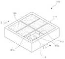
투수 블록(100)은 도 2에 도시된 바와 같이 블록(110)과, 화산석(120)을 포함하여 구성된다.The
블록(110)은 투수 블록의 틀을 구성하는 역할을 하며, 콘크리트 재질임이 바람직하다.
블록(110)은 사각 형태로 이루어질 수도 있으며, 심미감을 고려하여 다각형 또는 원형으로 형성될 수도 있다.The
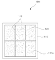
이때, 블록(110)의 상부에는 화산석(120)이 결합되기 위한 결합홈(111)이 형성되며, 상기 결합홈(111)은 복수로 형성됨이 바람직하다.At this time, the
이는, 결합홈(111)이 복수로 형성됨에 따라 격자 형태의 격벽(112)에 의해 구획되는데, 상기 격벽(112)에 의해 블록(110)의 강도가 보강될 수 있기 때문이다.This is because the plurality of
물론, 결합홈(111)이 복수로 형성된 것으로 한정되는 것은 아니며, 하나의 홈으로 형성될 수도 있다.Of course, the
본 명세서에서는 설명의 편의상, 격벽(112)에 의해 결합홈(111)이 복수로 구획된 것을 예로하여 설명하기로 한다.In the present specification, for convenience of description, the
상기 결합홈(111)의 형태 역시 다각형 또는 원형으로 형성될 수 있으며, 결합홈(111)의 형태를 한정하는 것은 아니다.The shape of the
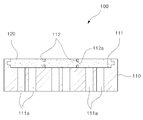
한편, 각각의 결합홈(111) 바닥에는 복수의 배수유로(111a)가 형성된다.Meanwhile, a plurality of
배수유로(111a)는 화산석(120)을 통해 투수(透水)된 빗물이 지면을 통해 지하로 빠져나가도록 하기 위한 관로이며, 결합홈(111)의 바닥으로부터 블록(110)의 저면을 관통하도록 형성된다.The
즉, 투수 블록(100)이 지면에 시공된 후에는 상기 블록(110)의 저면이 지면에 밀착된 상태가 되므로, 배수유로(111a)를 통해 배수되는 빗물은 바로 지면을 통해 지하로 투수될 수 있는 것이다.That is, since the bottom surface of the
한편, 상기 격벽(112)에는 이웃하는 결합홈(111)을 향해 관통된 엉김공(112a)이 형성됨이 바람직하다.On the other hand, the
엉김공(112a)은 화산석(120)이 결합홈(111)에 결합되는 과정에서 결합력을 견고하게 하기 위함이다.Agglomeration hole (112a) is to strengthen the bonding force in the process of the
즉, 화산석(120)은 결합홈(111)에 시공되기 전 점성의 상태를 유지하며, 결합홈(111)에 수용된 상태에서 경화됨에 따라 결합홈(111)에 완전한 결합이 이루어지는데, 점성의 화산석(120)이 결합홈(111)에 수용된 후 상기 엉김공(112a)을 통해 이웃하는 결합홈(111)의 화산석(120)과 엉기게 되면서 일체화되어 블록(110)에 대한 화산석(120)의 결합력을 극대화할 수 있는 것이다.That is, the
다음으로, 화산석(120)은 우천시(특히, 집중호우시) 빗물을 지하로 투수시키는 역할을 하며, 결합홈(111)에 결합된다.Next, the
화산석은 화산 분출물중 비교적 다공질(多孔質)이 많은 현무암의 암괴로서 자연미가 매우 아름다운 돌이며, 색상은 암질에 따라 다양하고 자연 본연의 색으로 중후 한감을 표현할 수 있으며 변질 및 변색이 없어 다양한 용도의 연출이 가능한 특징이 있다.Volcanic stone is a mass of basalt that is relatively porous among volcanic eruptions. It is a beautiful stone with natural beauty. The color varies according to the rock quality and can express profound feeling with natural color. There is a characteristic that can be directed.
상기한 바와 같이 화산석(120)은 화산석(120)을 이루는 알갱이들에 공극이 형성되어 있으므로, 투수 효과가 높은 기술적 특징이 있다.As described above, the
상기 화산석은 "대한민국 특허공개 10-2011-0136543"를 비롯하여 공지의 기술이므로 상세한 설명은 생략하도록 한다.Since the volcanic stone is a well-known technique including "Korean Patent Publication No. 10-2011-0136543", a detailed description thereof will be omitted.
이하, 상기한 구성으로 이루어진 투수 블록(100)의 결합 및 작용에 대하여 설명하도록 한다.Hereinafter, the coupling and operation of the
복수의 결합홈(111)이 구획된 블록(110)이 제작되어 제공된다.A
다음으로, 각각의 결합홈(111)에 화산석(120)을 수용시킨다.Next, the
이때, 화산석(120)은 콘크리트 타설시와 유사한 점성의 형태로 제공되므로, 각각의 결합홈(111)에 점성의 형태로 수용된다.At this time, since the
이때, 화산석(120)은 도 4에 도시된 바와 같이 격벽(112)의 엉김공(112a)을 통해 이웃하는 결합홈(111)으로 새어나가 이웃하는 화산석(120)과 엉겨 붙음으로써, 블록(110)의 결합홈(111)에서 경화된 화산석(120)의 결합력은 더욱 극대화될 수 있게 된다.At this time, the
한편, 상기 화산석(120)은 결합홈(111)에서만 경화될 수도 있으며, 결합홈(111)의 하방으로 형성된 배수유로(111a)에도 채워져 경화될 수도 있다.On the other hand, the
이때, 화산석(120)이 배수유로(111a)에 까지 채워져 경화된다면, 빗물의 배수 효과가 다소 떨어질 수는 있으나 투수 블록(100) 전체에 대한 강도를 높일 수 있는 이점이 있다.At this time, if the
상기와 같이 제작이 완료된 투수 블록(100)들은 인도의 지면에 시공되며, 우천시에 빗물은 화산석(120)을 통해 투수되어 배수유로(111a)를 통해 지면으로 흡수된다.As described above, the completed
이와 같이 화산석(120)을 통해 빗물의 투수가 신속하게 이루어짐에 따라, 인도에 빗물이 고이는 등의 불편함은 초래되지 않으며, 지하에 빗물이 스며듦으로써 지하수 해갈에 상당한 영향을 끼칠 수 있게 된다.
As the pitch of rainwater is quickly made through the
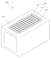
이하, 첨부된 도 5를 참조하여 본 고안의 제2실시예에 따른 우수관 투수 구조에 대하여 설명하도록 한다.Hereinafter, with reference to the accompanying Figure 5 will be described for the storm pipe permeable structure according to a second embodiment of the present invention.
우수관은 도로변의 가장자리에 시공되어 우천시 빗물을 강이나 바다로 안내하는 관로 역할을 한다.The storm pipe is constructed at the edge of the road and serves as a pipeline to guide rainwater to the river or the sea during rainy weather.
상기 우수관은 종래 기술에서 설명한 바와 같이 다양한 형태로 제공되며, 본 명세서에서는 설명의 편의상 사각 수로관을 예로 하여 설명하기로 한다.The storm pipe is provided in various forms as described in the prior art, and for the convenience of description, the storm pipe will be described as an example.
우수관(200)은 도 5에 도시된 바와 같이 관체(210)와, 유입부(220)를 포함하여 구성된다.
관체(210)는 빗물이 강이나 바다로 흘러갈 수 있도록 관로를 형성하며, 사각형태의 콘크리트 재질로 이루어진다.
이와 같은 관체(210)는 복수로 제공되어 도로변을 따라 연이어 결합됨으로써, 빗물을 배수하는 관로를 형성하게 된다.Such a
다음으로, 유입부(220)는 지면의 빗물이 관체(210)의 내부로 유입되는 부위이며, 관체(210)의 상면에 형성된다.Next, the
이때, 관체(210)의 상면은 지면에 노출되는 부위이며, 관체(210)의 하부는 지하에 매설되는 부위이다.At this time, the upper surface of the
상기 유입부(220)는 관체(210)의 상면에 형성된 통공(221)과, 상기 통공(221)에 결합된 그레이팅(222)과, 그레이팅(222)의 간격마다 결합된 화산석(223)으로 구성된다.The
통공(221)은 빗물이 관체(210)의 내부로 유입되기 위한 통로이며, 그의 형태는 제한되지 않는다.The through
통공(221)에 그레이팅(222)이 결합됨을 감안할 때, 그레이팅(222)의 제작을 용이하게 하기 위하여 상기 통공(221)은 사각 형태로 형성됨이 바람직하다.Given that the grating 222 is coupled to the through
그리고, 그레이팅(222)의 재질은 스틸 또는 석재(石材)로 이루어질 수 있다.And, the material of the grating 222 may be made of steel or stone (石材).
그리고, 화산석(223)은 지면의 빗물을 관체(210)의 내부로 투수시킴과 더불어, 이물질이 관체(210)의 내부로 유입되는 것을 방지하는 역할을 한다.In addition, the
즉, 도 5에 도시된 바와 같이, 화산석(223)이 그레이팅(222)의 간격을 메우도록 결합됨으로써, 담배꽁초 등의 이물질은 관체(210)의 내부로 전혀 유입될 수 없지만 투수 효과가 탁월한 화산석(223)으로 인해 빗물은 관체(210)의 내부로 무리 없이 유입될 수 있는 것이다.
That is, as shown in Figure 5, the
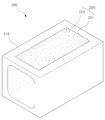
이하, 첨부된 도 6을 참조하여 본 고안의 제3실시예에 따른 우수관 투수 구조에 대하여 설명하도록 한다.Hereinafter, with reference to the accompanying Figure 6 will be described the storm pipe permeable structure according to a third embodiment of the present invention.
제3실시예 역시 사각 수로관을 예로 하여 설명하기로 한다.The third embodiment will also be described with an example of a rectangular water pipe.
사각 즉, 직육면체 형태의 관체(210)와, 관체(210)의 내부로 빗물이 유입되기 위한 유입부(220)로 구성된다.It consists of a square, that is, a rectangular parallelepiped
이때, 유입부(220)는 관체(210)의 상면에 형성된 통공(221)과, 화산석(223)으로 구성된다.At this time, the
통공(221)의 형태는 제한되지 않으나, 사각 형태로 형성됨이 바람직하다.The shape of the through
그리고, 화산석(223)은 관체(210)의 내부로 빗물을 투수시키며, 이물질을 거르는 역할을 한다.In addition, the
화산석(223)은 통공(221)에 결합되며, 화산석(223)이 통공(221)에 결합되는 방식은 전술한 실시예와 동일하다.The
이때, 설명의 편의상 관체(210)의 상면에 일체형의 화산석(223)이 결합된 것을 도시하였으나, 이에 한정되는 것은 아니며 화산석(223)을 복수의 개별체로 하여 결합시킬 수도 있다.In this case, for convenience of description, the integral
즉, 제1실시예에 개시된 투수 블록(100)의 구성과 같이, 격자를 이용해 복수의 공간을 구성한 후 각 공간에 화산석(223)을 결합시키는 것이다.That is, as in the configuration of the
이와 같이, 제3실시예에 따른 우수관 투수 구조는 도 6에 도시된 바와 같이 그레이팅 없이 이물질을 거르고 빗물을 관체 내부로 유입하여 강이나 바다로 배수시킬 수 있는 기술적 특징이 있다.
As described above, the storm pipe permeable structure according to the third embodiment has a technical feature of filtering foreign matters without grating and draining rainwater into the river or sea as shown in FIG. 6.
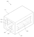
이하, 첨부된 도 7을 참조하여 본 고안의 제4실시예에 따른 우수관 투수 구조에 대하여 설명하도록 한다.Hereinafter, with reference to the accompanying Figure 7 will be described for the storm pipe permeable structure according to the fourth embodiment of the present invention.
제4실시예에 따른 우수관 투수 구조는 직육면체의 관체(210)와, 화산석(223)을 포함한다.The storm pipe permeable structure according to the fourth embodiment includes a
이때, 관체(210)의 저면과 양측면에는 관체(210)의 외부와 관통된 배출공(230)이 형성되며, 상기 배출공(230)에는 화산석(223)이 결합된다.At this time, the bottom and both sides of the
이때, 배출공(230)의 형태 역시 제한되지 않으며, 화산석(223)은 복수로 결합될 수 있다.At this time, the shape of the
즉, 제4실시예에 따른 우수관 투수 구조는 외부의 빗물을 관체(210) 내부로 유입시켜 강이나 바다로 배수시킴과 더불어 관체(210)의 저면이나 양측을 통해 지하로 배수시키는 기술적 특징이 있는 것이다.That is, the rain pipe permeable structure according to the fourth embodiment has a technical characteristic of draining the rainwater from the outside into the
집중호우시 강수량이 많을 경우, 관체(210)의 관로는 포화될 수 있는데 관체(210)의 내부를 따라 흐르는 빗물의 일부는 강이나 바다로 배수되며 빗물의 나머지는 관체(210)의 저면이나 양측의 화산석(223)을 통해 지하로 배출되도록 한 것이다.In case of heavy rainfall, the pipeline of the tubular 210 may be saturated. Part of the rainwater flowing along the interior of the tubular 210 is drained to the river or the sea, and the rest of the rainwater is the bottom or both sides of the tubular 210. Through
이에 따라, 빗물에 대한 배수 효율을 극대화할 수 있는 것이다.Accordingly, it is possible to maximize the drainage efficiency for rainwater.
이와 같은 제3 내지 제4실시예에 따른 우수관 투수 구조를 서로 혼합하여 배치함으로써 우수관에 대한 효율성을 극대화할 수 있다.
The storm pipe permeable structures according to the third to fourth embodiments may be mixed with each other to maximize the efficiency of the storm pipe.
지금까지 설명한 바와 같이 본 고안에 따른 투수 블록 및 우수관 투수 구조는 빗물에 대한 배수 효과를 극대화하여 홍수를 방지하고 빗물이 지하로 스며들도록 함으로써 지하수 고갈을 억제할 수 있도록 한 기술적 특징이 있다.As described above, the permeation block and the stormwater permeable structure according to the present invention have a technical feature that can prevent groundwater exhaustion by maximizing the drainage effect on rainwater and preventing flooding and allowing rainwater to penetrate underground.
이에 따라, 홍수로 인한 피해를 줄임과 더불어 자연환경을 향상시킬 수 있게 된다.Accordingly, it is possible to reduce the damage caused by the flood and improve the natural environment.
100 : 투수 블록 110 : 블록
111 : 결합홈 111a : 배수유로
112 : 격벽 112a : 엉김공
120,223 : 화산석 200 : 우수관
210 : 관체 220 : 유입부
221 : 통공 222 : 그레이팅
223 : 화산석 230 : 배출공100: pitcher block 110: block
111:
112: bulkhead 112a: tangle ball
120,223: Volcanic stone 200: Excellent view
210: tube 220: inlet
221: through-hole 222: grating
223: volcanic stone 230: discharge hole
Claims (10)
상기 블록의 결합홈으로부터 블록의 저면을 향해 형성된 복수의 배수유로;
상기 결합홈에 타설되어 양생을 거쳐 결합된 화산석:을 포함하여 구성된 투수 블록.A block in which a coupling groove having a predetermined depth is formed;
A plurality of drainage passages formed from the coupling groove of the block toward the bottom of the block;
A pitcher block comprising: a volcanic stone placed in the coupling groove and bonded through curing.
상기 결합홈은 격벽에 의해 복수로 구획되고, 각각의 결합홈마다 화산석이 양생되어 결합된 것을 특징으로 하는 투수 블록.The method of claim 1,
The coupling groove is partitioned into a plurality of partitions, the pitcher block, characterized in that the volcanic stone is cured and coupled to each coupling groove.
상기 격벽 및 블록의 내측면에는 엉김공이 형성되어, 결합홈에서 화산석의 양생시 상기 엉김공을 통해 이웃하는 결합홈의 화산석 및 블록의 내측면에 엉기도록 한 것을 특징으로 하는 투수 블록.3. The method according to claim 1 or 2,
The inner wall of the partition and the block is formed with a tangle hole, the pitcher block, characterized in that to entangle the inner surface of the volcanic stone and block of the neighboring coupling groove through the tangle hole during curing of the volcanic stone in the coupling groove.
상기 결합홈 및 화산석은 다각형 또는 원형인 것을 특징으로 하는 투수 블록.3. The method according to claim 1 or 2,
The coupling groove and the volcanic stone is a pitcher block, characterized in that the polygon or circle.
상기 유입부는 화산석을 포함하는 것을 특징으로 하는 우수관 투수 구조.In the storm pipe permeable structure including a pipe forming a pipeline toward a river or the sea, and an inlet formed in the upper portion of the pipe so that rainwater flows into the pipe of the pipe,
Rainwater pipe permeable structure, characterized in that the inlet comprises a volcanic stone.
상기 유입부는 블록의 관로를 향해 형성된 다각형 또는 원형의 통공과, 상기 통공에 결합된 화산석으로 구성된 것을 특징으로 하는 우수관 구조.6. The method of claim 5,
The inlet is an excellent pipe structure, characterized in that consisting of a polygonal or circular through-hole formed toward the conduit of the block, and the volcanic stone coupled to the through-hole.
상기 유입부는 관체의 관로를 향해 형성된 다각형 또는 원형의 통공과, 상기 통공에 결합된 그레이팅과, 상기 그레이팅의 간격을 메우는 화산석으로 구성된 것을 특징으로 하는 우수관 투수 구조.6. The method of claim 5,
The inlet is a water pipe permeable structure, characterized in that consisting of a polygonal or circular through-hole formed toward the pipeline of the pipe, the grating coupled to the through hole, the volcanic stone filling the gap of the grating.
상기 관체는 사각 수로관, 측구 수로관, 플룸관 중 어느 하나인 것을 특징으로 하는 우수관 투수 구조.8. The method according to any one of claims 5 to 7,
The pipe is an excellent pipe permeable structure, characterized in that any one of a square water pipe, a side channel pipe, a plume pipe.
상기 관체의 측면에는 배출공이 형성되며, 상기 배출공에는 화산석이 결합된 것을 특징으로 하는 우수관 투수 구조.
The method of claim 9,
Discharge holes are formed on the side of the tube, the discharge hole is characterized in that the storm pipe is combined with the volcanic stone.
Priority Applications (1)
| Application Number | Priority Date | Filing Date | Title |
|---|---|---|---|
| KR2020120008343U KR20140001756U (en) | 2012-09-18 | 2012-09-18 | A permeable block and a rainwater pipe permeable structure |
Applications Claiming Priority (1)
| Application Number | Priority Date | Filing Date | Title |
|---|---|---|---|
| KR2020120008343U KR20140001756U (en) | 2012-09-18 | 2012-09-18 | A permeable block and a rainwater pipe permeable structure |
Publications (1)
| Publication Number | Publication Date |
|---|---|
| KR20140001756U true KR20140001756U (en) | 2014-03-26 |
Family
ID=52442344
Family Applications (1)
| Application Number | Title | Priority Date | Filing Date |
|---|---|---|---|
| KR2020120008343U KR20140001756U (en) | 2012-09-18 | 2012-09-18 | A permeable block and a rainwater pipe permeable structure |
Country Status (1)
| Country | Link |
|---|---|
| KR (1) | KR20140001756U (en) |
Cited By (5)
| Publication number | Priority date | Publication date | Assignee | Title |
|---|---|---|---|---|
| KR20160037275A (en) * | 2014-09-26 | 2016-04-06 | 중앙대학교 산학협력단 | Polymer concrete unit and Division molding structure of the polymer concrete unit |
| KR20190039483A (en) * | 2019-04-01 | 2019-04-12 | 김창석 | Composition for civil engineering, manufacturing method of the same, road facility using the same and drainage facility using the same |
| KR102079681B1 (en) * | 2019-07-12 | 2020-02-19 | (주)성광종합기술개발 | Waterway Pipe Structure |
| KR102241363B1 (en) * | 2020-08-04 | 2021-04-16 | 에스비비 주식회사 | Sidewalk type water storage facility and method for constructing this same |
| WO2023242623A1 (en) * | 2022-06-15 | 2023-12-21 | Sindhu Gopinath | A structure for a drain segment of a storm drain system |
-
2012
- 2012-09-18 KR KR2020120008343U patent/KR20140001756U/en not_active Application Discontinuation
Cited By (5)
| Publication number | Priority date | Publication date | Assignee | Title |
|---|---|---|---|---|
| KR20160037275A (en) * | 2014-09-26 | 2016-04-06 | 중앙대학교 산학협력단 | Polymer concrete unit and Division molding structure of the polymer concrete unit |
| KR20190039483A (en) * | 2019-04-01 | 2019-04-12 | 김창석 | Composition for civil engineering, manufacturing method of the same, road facility using the same and drainage facility using the same |
| KR102079681B1 (en) * | 2019-07-12 | 2020-02-19 | (주)성광종합기술개발 | Waterway Pipe Structure |
| KR102241363B1 (en) * | 2020-08-04 | 2021-04-16 | 에스비비 주식회사 | Sidewalk type water storage facility and method for constructing this same |
| WO2023242623A1 (en) * | 2022-06-15 | 2023-12-21 | Sindhu Gopinath | A structure for a drain segment of a storm drain system |
Similar Documents
| Publication | Publication Date | Title |
|---|---|---|
| CN108193758B (en) | Sponge urban road storing and draining structure | |
| CN104032793B (en) | The anti-rain-impact system of garden type for residential quarter road | |
| CN106917522B (en) | A kind of Outdoor Parking position system based on sponge the idea of the city | |
| ES2767374T3 (en) | Method for cooling a sports field | |
| KR20140001756U (en) | A permeable block and a rainwater pipe permeable structure | |
| CN206571217U (en) | Outdoor Parking position system based on sponge the idea of the city | |
| KR101020718B1 (en) | Seepaging structure using absorbent pavement geo-cell for material and rainforced of ground | |
| JP4284665B2 (en) | Drainage structure of gutter | |
| CN106351309A (en) | Urban road rainwater detention and seepage system applicable to North | |
| KR101510615B1 (en) | Penetration type rainwater storage tank and construction method of the same | |
| CN104878827A (en) | Road drainage structure | |
| KR101201544B1 (en) | Underground Penetration Type Side Gutter Assembly | |
| JP5396368B2 (en) | Pavement structure | |
| CN203977495U (en) | The anti-rainwater impact system of garden type for residential quarter road | |
| CN204530376U (en) | Prevention waterlogging disappears the smooth town road structure in rain sewage sidewalk | |
| CN204690894U (en) | Road drainage structure | |
| KR20140098583A (en) | Flood reduction and penetration for promoting the penetration type road system | |
| CN204059138U (en) | Road rain water percolating device | |
| JP5252652B2 (en) | Rainwater-based road structure on the road | |
| KR20120135996A (en) | Block include drains | |
| KR200462236Y1 (en) | A case for water permeable sidewalk flagstone | |
| KR100799733B1 (en) | Stormwater storage system | |
| CN107460944B (en) | Road surface rainwater discarding and comprehensive utilization system | |
| JP2016079592A (en) | Pavement structure | |
| KR101663914B1 (en) | Rainwater infilration structures |
Legal Events
| Date | Code | Title | Description |
|---|---|---|---|
| A201 | Request for examination | ||
| E902 | Notification of reason for refusal | ||
| E601 | Decision to refuse application |