KR20130137178A - Adhesive-layer-equipped transparent surface material, display device, and methods for producing same - Google Patents
Adhesive-layer-equipped transparent surface material, display device, and methods for producing same Download PDFInfo
- Publication number
- KR20130137178A KR20130137178A KR20137011811A KR20137011811A KR20130137178A KR 20130137178 A KR20130137178 A KR 20130137178A KR 20137011811 A KR20137011811 A KR 20137011811A KR 20137011811 A KR20137011811 A KR 20137011811A KR 20130137178 A KR20130137178 A KR 20130137178A
- Authority
- KR
- South Korea
- Prior art keywords
- face material
- adhesion layer
- transparent face
- curable
- resin composition
- Prior art date
Links
Images


Classifications
-
- C—CHEMISTRY; METALLURGY
- C09—DYES; PAINTS; POLISHES; NATURAL RESINS; ADHESIVES; COMPOSITIONS NOT OTHERWISE PROVIDED FOR; APPLICATIONS OF MATERIALS NOT OTHERWISE PROVIDED FOR
- C09J—ADHESIVES; NON-MECHANICAL ASPECTS OF ADHESIVE PROCESSES IN GENERAL; ADHESIVE PROCESSES NOT PROVIDED FOR ELSEWHERE; USE OF MATERIALS AS ADHESIVES
- C09J175/00—Adhesives based on polyureas or polyurethanes; Adhesives based on derivatives of such polymers
- C09J175/04—Polyurethanes
- C09J175/08—Polyurethanes from polyethers
-
- B—PERFORMING OPERATIONS; TRANSPORTING
- B32—LAYERED PRODUCTS
- B32B—LAYERED PRODUCTS, i.e. PRODUCTS BUILT-UP OF STRATA OF FLAT OR NON-FLAT, e.g. CELLULAR OR HONEYCOMB, FORM
- B32B27/00—Layered products comprising a layer of synthetic resin
- B32B27/06—Layered products comprising a layer of synthetic resin as the main or only constituent of a layer, which is next to another layer of the same or of a different material
-
- B—PERFORMING OPERATIONS; TRANSPORTING
- B32—LAYERED PRODUCTS
- B32B—LAYERED PRODUCTS, i.e. PRODUCTS BUILT-UP OF STRATA OF FLAT OR NON-FLAT, e.g. CELLULAR OR HONEYCOMB, FORM
- B32B3/00—Layered products comprising a layer with external or internal discontinuities or unevennesses, or a layer of non-planar form; Layered products having particular features of form
- B32B3/02—Layered products comprising a layer with external or internal discontinuities or unevennesses, or a layer of non-planar form; Layered products having particular features of form characterised by features of form at particular places, e.g. in edge regions
-
- B—PERFORMING OPERATIONS; TRANSPORTING
- B32—LAYERED PRODUCTS
- B32B—LAYERED PRODUCTS, i.e. PRODUCTS BUILT-UP OF STRATA OF FLAT OR NON-FLAT, e.g. CELLULAR OR HONEYCOMB, FORM
- B32B3/00—Layered products comprising a layer with external or internal discontinuities or unevennesses, or a layer of non-planar form; Layered products having particular features of form
- B32B3/10—Layered products comprising a layer with external or internal discontinuities or unevennesses, or a layer of non-planar form; Layered products having particular features of form characterised by a discontinuous layer, i.e. formed of separate pieces of material
-
- B—PERFORMING OPERATIONS; TRANSPORTING
- B32—LAYERED PRODUCTS
- B32B—LAYERED PRODUCTS, i.e. PRODUCTS BUILT-UP OF STRATA OF FLAT OR NON-FLAT, e.g. CELLULAR OR HONEYCOMB, FORM
- B32B37/00—Methods or apparatus for laminating, e.g. by curing or by ultrasonic bonding
- B32B37/10—Methods or apparatus for laminating, e.g. by curing or by ultrasonic bonding characterised by the pressing technique, e.g. using action of vacuum or fluid pressure
-
- B—PERFORMING OPERATIONS; TRANSPORTING
- B32—LAYERED PRODUCTS
- B32B—LAYERED PRODUCTS, i.e. PRODUCTS BUILT-UP OF STRATA OF FLAT OR NON-FLAT, e.g. CELLULAR OR HONEYCOMB, FORM
- B32B37/00—Methods or apparatus for laminating, e.g. by curing or by ultrasonic bonding
- B32B37/14—Methods or apparatus for laminating, e.g. by curing or by ultrasonic bonding characterised by the properties of the layers
-
- B—PERFORMING OPERATIONS; TRANSPORTING
- B32—LAYERED PRODUCTS
- B32B—LAYERED PRODUCTS, i.e. PRODUCTS BUILT-UP OF STRATA OF FLAT OR NON-FLAT, e.g. CELLULAR OR HONEYCOMB, FORM
- B32B7/00—Layered products characterised by the relation between layers; Layered products characterised by the relative orientation of features between layers, or by the relative values of a measurable parameter between layers, i.e. products comprising layers having different physical, chemical or physicochemical properties; Layered products characterised by the interconnection of layers
- B32B7/04—Interconnection of layers
- B32B7/06—Interconnection of layers permitting easy separation
-
- B—PERFORMING OPERATIONS; TRANSPORTING
- B32—LAYERED PRODUCTS
- B32B—LAYERED PRODUCTS, i.e. PRODUCTS BUILT-UP OF STRATA OF FLAT OR NON-FLAT, e.g. CELLULAR OR HONEYCOMB, FORM
- B32B7/00—Layered products characterised by the relation between layers; Layered products characterised by the relative orientation of features between layers, or by the relative values of a measurable parameter between layers, i.e. products comprising layers having different physical, chemical or physicochemical properties; Layered products characterised by the interconnection of layers
- B32B7/04—Interconnection of layers
- B32B7/12—Interconnection of layers using interposed adhesives or interposed materials with bonding properties
-
- C—CHEMISTRY; METALLURGY
- C09—DYES; PAINTS; POLISHES; NATURAL RESINS; ADHESIVES; COMPOSITIONS NOT OTHERWISE PROVIDED FOR; APPLICATIONS OF MATERIALS NOT OTHERWISE PROVIDED FOR
- C09J—ADHESIVES; NON-MECHANICAL ASPECTS OF ADHESIVE PROCESSES IN GENERAL; ADHESIVE PROCESSES NOT PROVIDED FOR ELSEWHERE; USE OF MATERIALS AS ADHESIVES
- C09J4/00—Adhesives based on organic non-macromolecular compounds having at least one polymerisable carbon-to-carbon unsaturated bond ; adhesives, based on monomers of macromolecular compounds of groups C09J183/00 - C09J183/16
-
- C—CHEMISTRY; METALLURGY
- C09—DYES; PAINTS; POLISHES; NATURAL RESINS; ADHESIVES; COMPOSITIONS NOT OTHERWISE PROVIDED FOR; APPLICATIONS OF MATERIALS NOT OTHERWISE PROVIDED FOR
- C09J—ADHESIVES; NON-MECHANICAL ASPECTS OF ADHESIVE PROCESSES IN GENERAL; ADHESIVE PROCESSES NOT PROVIDED FOR ELSEWHERE; USE OF MATERIALS AS ADHESIVES
- C09J7/00—Adhesives in the form of films or foils
- C09J7/20—Adhesives in the form of films or foils characterised by their carriers
- C09J7/22—Plastics; Metallised plastics
-
- C—CHEMISTRY; METALLURGY
- C09—DYES; PAINTS; POLISHES; NATURAL RESINS; ADHESIVES; COMPOSITIONS NOT OTHERWISE PROVIDED FOR; APPLICATIONS OF MATERIALS NOT OTHERWISE PROVIDED FOR
- C09J—ADHESIVES; NON-MECHANICAL ASPECTS OF ADHESIVE PROCESSES IN GENERAL; ADHESIVE PROCESSES NOT PROVIDED FOR ELSEWHERE; USE OF MATERIALS AS ADHESIVES
- C09J7/00—Adhesives in the form of films or foils
- C09J7/30—Adhesives in the form of films or foils characterised by the adhesive composition
- C09J7/38—Pressure-sensitive adhesives [PSA]
- C09J7/381—Pressure-sensitive adhesives [PSA] based on macromolecular compounds obtained by reactions involving only carbon-to-carbon unsaturated bonds
- C09J7/385—Acrylic polymers
-
- G—PHYSICS
- G09—EDUCATION; CRYPTOGRAPHY; DISPLAY; ADVERTISING; SEALS
- G09F—DISPLAYING; ADVERTISING; SIGNS; LABELS OR NAME-PLATES; SEALS
- G09F9/00—Indicating arrangements for variable information in which the information is built-up on a support by selection or combination of individual elements
-
- B—PERFORMING OPERATIONS; TRANSPORTING
- B32—LAYERED PRODUCTS
- B32B—LAYERED PRODUCTS, i.e. PRODUCTS BUILT-UP OF STRATA OF FLAT OR NON-FLAT, e.g. CELLULAR OR HONEYCOMB, FORM
- B32B37/00—Methods or apparatus for laminating, e.g. by curing or by ultrasonic bonding
- B32B37/10—Methods or apparatus for laminating, e.g. by curing or by ultrasonic bonding characterised by the pressing technique, e.g. using action of vacuum or fluid pressure
- B32B2037/1063—Methods or apparatus for laminating, e.g. by curing or by ultrasonic bonding characterised by the pressing technique, e.g. using action of vacuum or fluid pressure using an electrostatic force
-
- B—PERFORMING OPERATIONS; TRANSPORTING
- B32—LAYERED PRODUCTS
- B32B—LAYERED PRODUCTS, i.e. PRODUCTS BUILT-UP OF STRATA OF FLAT OR NON-FLAT, e.g. CELLULAR OR HONEYCOMB, FORM
- B32B2405/00—Adhesive articles, e.g. adhesive tapes
-
- B—PERFORMING OPERATIONS; TRANSPORTING
- B32—LAYERED PRODUCTS
- B32B—LAYERED PRODUCTS, i.e. PRODUCTS BUILT-UP OF STRATA OF FLAT OR NON-FLAT, e.g. CELLULAR OR HONEYCOMB, FORM
- B32B2457/00—Electrical equipment
- B32B2457/20—Displays, e.g. liquid crystal displays, plasma displays
-
- B—PERFORMING OPERATIONS; TRANSPORTING
- B32—LAYERED PRODUCTS
- B32B—LAYERED PRODUCTS, i.e. PRODUCTS BUILT-UP OF STRATA OF FLAT OR NON-FLAT, e.g. CELLULAR OR HONEYCOMB, FORM
- B32B2457/00—Electrical equipment
- B32B2457/20—Displays, e.g. liquid crystal displays, plasma displays
- B32B2457/202—LCD, i.e. liquid crystal displays
-
- C—CHEMISTRY; METALLURGY
- C09—DYES; PAINTS; POLISHES; NATURAL RESINS; ADHESIVES; COMPOSITIONS NOT OTHERWISE PROVIDED FOR; APPLICATIONS OF MATERIALS NOT OTHERWISE PROVIDED FOR
- C09J—ADHESIVES; NON-MECHANICAL ASPECTS OF ADHESIVE PROCESSES IN GENERAL; ADHESIVE PROCESSES NOT PROVIDED FOR ELSEWHERE; USE OF MATERIALS AS ADHESIVES
- C09J2203/00—Applications of adhesives in processes or use of adhesives in the form of films or foils
- C09J2203/318—Applications of adhesives in processes or use of adhesives in the form of films or foils for the production of liquid crystal displays
-
- C—CHEMISTRY; METALLURGY
- C09—DYES; PAINTS; POLISHES; NATURAL RESINS; ADHESIVES; COMPOSITIONS NOT OTHERWISE PROVIDED FOR; APPLICATIONS OF MATERIALS NOT OTHERWISE PROVIDED FOR
- C09J—ADHESIVES; NON-MECHANICAL ASPECTS OF ADHESIVE PROCESSES IN GENERAL; ADHESIVE PROCESSES NOT PROVIDED FOR ELSEWHERE; USE OF MATERIALS AS ADHESIVES
- C09J2301/00—Additional features of adhesives in the form of films or foils
- C09J2301/20—Additional features of adhesives in the form of films or foils characterized by the structural features of the adhesive itself
- C09J2301/204—Additional features of adhesives in the form of films or foils characterized by the structural features of the adhesive itself the adhesive coating being discontinuous
-
- C—CHEMISTRY; METALLURGY
- C09—DYES; PAINTS; POLISHES; NATURAL RESINS; ADHESIVES; COMPOSITIONS NOT OTHERWISE PROVIDED FOR; APPLICATIONS OF MATERIALS NOT OTHERWISE PROVIDED FOR
- C09J—ADHESIVES; NON-MECHANICAL ASPECTS OF ADHESIVE PROCESSES IN GENERAL; ADHESIVE PROCESSES NOT PROVIDED FOR ELSEWHERE; USE OF MATERIALS AS ADHESIVES
- C09J2301/00—Additional features of adhesives in the form of films or foils
- C09J2301/20—Additional features of adhesives in the form of films or foils characterized by the structural features of the adhesive itself
- C09J2301/21—Additional features of adhesives in the form of films or foils characterized by the structural features of the adhesive itself the adhesive layer being formed by alternating adhesive areas of different nature
-
- C—CHEMISTRY; METALLURGY
- C09—DYES; PAINTS; POLISHES; NATURAL RESINS; ADHESIVES; COMPOSITIONS NOT OTHERWISE PROVIDED FOR; APPLICATIONS OF MATERIALS NOT OTHERWISE PROVIDED FOR
- C09J—ADHESIVES; NON-MECHANICAL ASPECTS OF ADHESIVE PROCESSES IN GENERAL; ADHESIVE PROCESSES NOT PROVIDED FOR ELSEWHERE; USE OF MATERIALS AS ADHESIVES
- C09J2301/00—Additional features of adhesives in the form of films or foils
- C09J2301/30—Additional features of adhesives in the form of films or foils characterized by the chemical, physicochemical or physical properties of the adhesive or the carrier
- C09J2301/312—Additional features of adhesives in the form of films or foils characterized by the chemical, physicochemical or physical properties of the adhesive or the carrier parameters being the characterizing feature
-
- C—CHEMISTRY; METALLURGY
- C09—DYES; PAINTS; POLISHES; NATURAL RESINS; ADHESIVES; COMPOSITIONS NOT OTHERWISE PROVIDED FOR; APPLICATIONS OF MATERIALS NOT OTHERWISE PROVIDED FOR
- C09J—ADHESIVES; NON-MECHANICAL ASPECTS OF ADHESIVE PROCESSES IN GENERAL; ADHESIVE PROCESSES NOT PROVIDED FOR ELSEWHERE; USE OF MATERIALS AS ADHESIVES
- C09J2471/00—Presence of polyether
-
- C—CHEMISTRY; METALLURGY
- C09—DYES; PAINTS; POLISHES; NATURAL RESINS; ADHESIVES; COMPOSITIONS NOT OTHERWISE PROVIDED FOR; APPLICATIONS OF MATERIALS NOT OTHERWISE PROVIDED FOR
- C09J—ADHESIVES; NON-MECHANICAL ASPECTS OF ADHESIVE PROCESSES IN GENERAL; ADHESIVE PROCESSES NOT PROVIDED FOR ELSEWHERE; USE OF MATERIALS AS ADHESIVES
- C09J2475/00—Presence of polyurethane
-
- C—CHEMISTRY; METALLURGY
- C09—DYES; PAINTS; POLISHES; NATURAL RESINS; ADHESIVES; COMPOSITIONS NOT OTHERWISE PROVIDED FOR; APPLICATIONS OF MATERIALS NOT OTHERWISE PROVIDED FOR
- C09K—MATERIALS FOR MISCELLANEOUS APPLICATIONS, NOT PROVIDED FOR ELSEWHERE
- C09K2323/00—Functional layers of liquid crystal optical display excluding electroactive liquid crystal layer characterised by chemical composition
- C09K2323/05—Bonding or intermediate layer characterised by chemical composition, e.g. sealant or spacer
- C09K2323/059—Unsaturated aliphatic polymer, e.g. vinyl
-
- G—PHYSICS
- G02—OPTICS
- G02F—OPTICAL DEVICES OR ARRANGEMENTS FOR THE CONTROL OF LIGHT BY MODIFICATION OF THE OPTICAL PROPERTIES OF THE MEDIA OF THE ELEMENTS INVOLVED THEREIN; NON-LINEAR OPTICS; FREQUENCY-CHANGING OF LIGHT; OPTICAL LOGIC ELEMENTS; OPTICAL ANALOGUE/DIGITAL CONVERTERS
- G02F1/00—Devices or arrangements for the control of the intensity, colour, phase, polarisation or direction of light arriving from an independent light source, e.g. switching, gating or modulating; Non-linear optics
- G02F1/01—Devices or arrangements for the control of the intensity, colour, phase, polarisation or direction of light arriving from an independent light source, e.g. switching, gating or modulating; Non-linear optics for the control of the intensity, phase, polarisation or colour
- G02F1/13—Devices or arrangements for the control of the intensity, colour, phase, polarisation or direction of light arriving from an independent light source, e.g. switching, gating or modulating; Non-linear optics for the control of the intensity, phase, polarisation or colour based on liquid crystals, e.g. single liquid crystal display cells
- G02F1/133—Constructional arrangements; Operation of liquid crystal cells; Circuit arrangements
- G02F1/1333—Constructional arrangements; Manufacturing methods
- G02F1/133308—Support structures for LCD panels, e.g. frames or bezels
- G02F1/133331—Cover glasses
-
- G—PHYSICS
- G02—OPTICS
- G02F—OPTICAL DEVICES OR ARRANGEMENTS FOR THE CONTROL OF LIGHT BY MODIFICATION OF THE OPTICAL PROPERTIES OF THE MEDIA OF THE ELEMENTS INVOLVED THEREIN; NON-LINEAR OPTICS; FREQUENCY-CHANGING OF LIGHT; OPTICAL LOGIC ELEMENTS; OPTICAL ANALOGUE/DIGITAL CONVERTERS
- G02F1/00—Devices or arrangements for the control of the intensity, colour, phase, polarisation or direction of light arriving from an independent light source, e.g. switching, gating or modulating; Non-linear optics
- G02F1/01—Devices or arrangements for the control of the intensity, colour, phase, polarisation or direction of light arriving from an independent light source, e.g. switching, gating or modulating; Non-linear optics for the control of the intensity, phase, polarisation or colour
- G02F1/13—Devices or arrangements for the control of the intensity, colour, phase, polarisation or direction of light arriving from an independent light source, e.g. switching, gating or modulating; Non-linear optics for the control of the intensity, phase, polarisation or colour based on liquid crystals, e.g. single liquid crystal display cells
- G02F1/133—Constructional arrangements; Operation of liquid crystal cells; Circuit arrangements
- G02F1/1333—Constructional arrangements; Manufacturing methods
- G02F1/1335—Structural association of cells with optical devices, e.g. polarisers or reflectors
- G02F1/133509—Filters, e.g. light shielding masks
- G02F1/133512—Light shielding layers, e.g. black matrix
-
- G—PHYSICS
- G02—OPTICS
- G02F—OPTICAL DEVICES OR ARRANGEMENTS FOR THE CONTROL OF LIGHT BY MODIFICATION OF THE OPTICAL PROPERTIES OF THE MEDIA OF THE ELEMENTS INVOLVED THEREIN; NON-LINEAR OPTICS; FREQUENCY-CHANGING OF LIGHT; OPTICAL LOGIC ELEMENTS; OPTICAL ANALOGUE/DIGITAL CONVERTERS
- G02F2202/00—Materials and properties
- G02F2202/28—Adhesive materials or arrangements
-
- Y—GENERAL TAGGING OF NEW TECHNOLOGICAL DEVELOPMENTS; GENERAL TAGGING OF CROSS-SECTIONAL TECHNOLOGIES SPANNING OVER SEVERAL SECTIONS OF THE IPC; TECHNICAL SUBJECTS COVERED BY FORMER USPC CROSS-REFERENCE ART COLLECTIONS [XRACs] AND DIGESTS
- Y10—TECHNICAL SUBJECTS COVERED BY FORMER USPC
- Y10T—TECHNICAL SUBJECTS COVERED BY FORMER US CLASSIFICATION
- Y10T156/00—Adhesive bonding and miscellaneous chemical manufacture
- Y10T156/10—Methods of surface bonding and/or assembly therefor
-
- Y—GENERAL TAGGING OF NEW TECHNOLOGICAL DEVELOPMENTS; GENERAL TAGGING OF CROSS-SECTIONAL TECHNOLOGIES SPANNING OVER SEVERAL SECTIONS OF THE IPC; TECHNICAL SUBJECTS COVERED BY FORMER USPC CROSS-REFERENCE ART COLLECTIONS [XRACs] AND DIGESTS
- Y10—TECHNICAL SUBJECTS COVERED BY FORMER USPC
- Y10T—TECHNICAL SUBJECTS COVERED BY FORMER US CLASSIFICATION
- Y10T428/00—Stock material or miscellaneous articles
- Y10T428/14—Layer or component removable to expose adhesive
- Y10T428/1462—Polymer derived from material having at least one acrylic or alkacrylic group or the nitrile or amide derivative thereof [e.g., acrylamide, acrylate ester, etc.]
-
- Y—GENERAL TAGGING OF NEW TECHNOLOGICAL DEVELOPMENTS; GENERAL TAGGING OF CROSS-SECTIONAL TECHNOLOGIES SPANNING OVER SEVERAL SECTIONS OF THE IPC; TECHNICAL SUBJECTS COVERED BY FORMER USPC CROSS-REFERENCE ART COLLECTIONS [XRACs] AND DIGESTS
- Y10—TECHNICAL SUBJECTS COVERED BY FORMER USPC
- Y10T—TECHNICAL SUBJECTS COVERED BY FORMER US CLASSIFICATION
- Y10T428/00—Stock material or miscellaneous articles
- Y10T428/24—Structurally defined web or sheet [e.g., overall dimension, etc.]
- Y10T428/24777—Edge feature
Abstract
다른 면재 (표시 패널 등) 와의 첩합이 간편하고, 다른 면재와 첩합했을 때에, 다른 면재와 점착층의 계면에 공극이 잔존하기 어려운 점착층이 형성된 투명 면재를 제공한다.
보호판 (10) (투명 면재) 의 적어도 일방의 표면에 점착층 (14) 을 구비하고, 점착층 (14) 이, 보호판 (10) 의 표면을 따라 확산되는 층상부 (18) 와 층상부 (18) 의 주연을 둘러싸는 언상부 (20) 를 갖고, 층상부 (18) 의 35 ℃ 에 있어서의 전단 탄성률이 0.5 ∼ 100 ㎪ 인 점착층이 형성된 투명 면재.When bonding with another face material (display panel etc.) is easy and when bonding together with another face material, the transparent face material in which the adhesion layer with which an air gap is hard to remain in the interface of another face material and an adhesion layer is formed.
At least one surface of the protective plate 10 (transparent face material) is provided with an adhesive layer 14, and the adhesive layer 14 diffuses along the surface of the protective plate 10 and the layered portion 18. The transparent face material which has the frozen-up part 20 surrounding the periphery of (), and the adhesive layer whose shear elastic modulus in 35 degreeC of layered part 18 is 0.5-100 GPa.
Description
본 발명은 점착층이 형성된 투명 면재, 투명 면재에 의해 표시 패널이 보호된 표시 장치, 및 그것들의 제조 방법에 관한 것이다.BACKGROUND OF THE
투명 면재 (보호판) 에 의해 표시 패널이 보호된 표시 장치로는 하기의 것이 알려져 있다. 예를 들어, 표시 패널과 보호판을 점착 시트를 개재하여 첩합 (貼合) 한 표시 장치이다 (특허문헌 1, 2 참조).The following are known as a display apparatus with which a display panel was protected by the transparent face material (protective plate). For example, it is a display apparatus which bonded together a display panel and a protective plate through an adhesive sheet (refer
표시 패널과 보호판의 첩합은, 표시 패널 또는 보호판과 점착 시트의 계면에 공극이 잔존하지 않도록, 하기 방법에 의해 실시되는 경우가 있다.Bonding of a display panel and a protective plate may be performed by the following method so that a space | gap does not remain in the interface of a display panel or a protective plate, and an adhesive sheet.
예를 들어, 감압 분위기하에서 표시 패널과 보호판을 점착 시트를 개재하여 첩합한 후, 이것을 대기압 분위기하로 되돌리는 방법이다.For example, after bonding a display panel and a protective plate together through an adhesive sheet in a pressure-reduced atmosphere, it is a method of returning this to atmospheric pressure atmosphere.
그 방법에 의하면, 도 9 에 나타내는 바와 같이, 감압 분위기하에서 표시 패널 (50) 과 보호판 (10) 을 점착 시트 (100) 를 개재하여 첩합했을 때에, 표시 패널 (50) 또는 보호판 (10) 과 점착 시트 (100) 의 계면에 독립적인 공극 (110) 이 잔존하고 있어도, 이것을 대기압 분위기하로 되돌림으로써, 공극 (110) 내의 압력 (감압인 채) 과 점착 시트 (100) 에 가해지는 압력 (대기압) 의 차압에 의해 공극 (110) 의 체적이 감소되고, 공극 (110) 은 소실된다.According to the method, as shown in FIG. 9, when the
그러나, 표시 패널 (50) 과 보호판 (10) 을 점착 시트 (100) 를 개재하여 첩합하는 경우, 도 10 에 나타내는 바와 같이, 점착 시트 (100) 의 주연 (周緣) 에, 외부에 개방된 공극 (120) 이 형성되는 경우가 많다. 감압 분위기하에서 표시 패널 (50) 과 보호판 (10) 을 점착 시트 (100) 를 개재하여 첩합한 것을 대기압 분위기하로 되돌렸을 때, 외부에 개방된 공극 (120) 내의 압력도 대기압으로 돌아오기 때문에, 공극 (120) 의 체적은 감소되지 않고, 공극 (120) 은 잔존한다.However, in the case where the
또한 그 방법에서는, 표시 패널 및 보호판 중 어느 일방의 면재에 점착 시트를 첩합한 후, 나머지 면재를 점착 시트에 첩합할 필요가 있다. 즉 첩합 공정이 2 회 필요하기 때문에, 표시 패널과 보호판의 첩합이 번잡하다.Moreover, in this method, after bonding an adhesive sheet to the face material of any one of a display panel and a protective plate, it is necessary to bond the remaining face material to an adhesive sheet. That is, since the bonding process is required twice, the bonding of the display panel and the protective plate is complicated.
본 발명은, 다른 면재 (표시 패널 등) 와의 첩합이 간편하고, 다른 면재와 첩합했을 때에, 다른 면재와 점착층의 계면에 공극이 잔존하기 어려운 점착층이 형성된 투명 면재 ; 투명 면재와 점착층의 계면에 있어서의 공극의 발생이 충분히 억제되고, 또한 다른 면재와의 첩합이 간편하고, 다른 면재와 첩합했을 때에도, 다른 면재와 점착층의 계면에 공극이 잔존하기 어려운, 점착층이 형성된 투명 면재를 제조하는 방법 ; 표시 패널과 점착층의 계면에 있어서의 공극의 발생이 충분히 억제된 표시 장치 ; 및 표시 패널과 투명 면재 (보호판) 의 첩합이 간편하고, 표시 패널과 점착층의 계면에 공극이 잔존하기 어려운 표시 장치의 제조 방법을 제공한다.The present invention relates to a transparent face material having a pressure-sensitive adhesive layer in which bonding with other face materials (such as a display panel) is easy and in which an air gap hardly remains at the interface between the other face material and the pressure-sensitive adhesive layer when bonded with other face materials; The generation | occurrence | production of the space | gap in the interface of a transparent face material and an adhesion layer is fully suppressed, and bonding with another face material is easy, and even when it bonds with another face material, it is hard for a space to remain at the interface of another face material and an adhesion layer. A method of manufacturing a layered transparent face material; A display device in which generation of voids at the interface between the display panel and the adhesive layer is sufficiently suppressed; And a display device and a method of manufacturing a display device in which bonding of the display panel and the transparent face material (protective plate) is simple and in which voids hardly remain at the interface between the display panel and the adhesive layer.
본 발명의 점착층이 형성된 투명 면재는, 투명 면재와, 투명 면재의 적어도 일방의 표면에 형성된 점착층을 갖는 점착층이 형성된 투명 면재로서, 점착층이, 투명 면재의 표면을 따라 확산되는 층상부와, 층상부의 주연을 둘러싸는 언상 (堰狀) 부를 갖고, 상기 층상부의, 35 ℃ 에 있어서의 전단 탄성률이 0.5 ∼ 100 ㎪ 인 것을 특징으로 하는 점착층이 형성된 투명 면재이다.The transparent face material with an adhesive layer of the present invention is a transparent face material with a pressure-sensitive adhesive layer having a transparent face material and a pressure-sensitive adhesive layer formed on at least one surface of the transparent face material, and a layered portion in which the pressure-sensitive adhesive layer diffuses along the surface of the transparent face material. And a frozen portion surrounding the periphery of the layered portion, wherein the shear modulus at 35 ° C of the layered portion is 0.5 to 100 GPa.
상기 층상부가 하기 경화성 화합물 (II) 및 하기 비경화성 올리고머 (D) 를 함유하는 층상부 형성용 경화성 수지 조성물의 경화물로 이루어지는 것이 바람직하다.It is preferable that the said layer part consists of hardened | cured material of the curable resin composition for layer part formation containing the following curable compound (II) and the following non-curable oligomer (D).
경화성 화합물 (II) : 경화성 수지 조성물의 경화시에 경화 반응하는 경화성 화합물의 1 종 이상으로 이루어지고, 그 경화성 화합물의 적어도 1 종은 상기 경화성 수지 조성물의 경화시에 반응하지 않는 수산기를 갖는다.Curable compound (II): It consists of 1 or more types of curable compounds which harden-cure at the time of hardening of curable resin composition, and at least 1 type of this curable compound has the hydroxyl group which does not react at the time of hardening of the said curable resin composition.
비경화성 올리고머 (D) : 경화성 수지 조성물의 경화시에 상기 경화성 화합물 (II) 와 경화 반응하지 않고, 또한 수산기를 갖는 올리고머.Non-curable oligomer (D): The oligomer which does not harden-react with the said curable compound (II) at the time of hardening of curable resin composition, and has a hydroxyl group.
상기 경화성 화합물 (II) 가, 경화성기를 갖고, 또한 수산기를 갖는 모노머를 함유하는 것이 바람직하다.It is preferable that the said curable compound (II) has a curable group, and also contains the monomer which has a hydroxyl group.
상기 경화성 화합물 (II) 가, 경화성기를 갖고, 또한 수평균 분자량이 1000 ∼ 100000 인 올리고머 (A'), 및 경화성기를 갖고, 또한 분자량이 125 ∼ 600 인 모노머 (B') 를 함유하고, 그 모노머 (B') 가 수산기를 갖는 모노머 (B3) 을 함유하는 것이 바람직하다.The curable compound (II) has a curable group, further has an oligomer (A ') having a number average molecular weight of 1000 to 100000 and a curable group, and further contains a monomer (B') having a molecular weight of 125 to 600, the monomer It is preferable that (B ') contains the monomer (B3) which has a hydroxyl group.
상기 비경화성 올리고머 (D) 가 폴리옥시알킬렌폴리올이고, 또한 상기 올리고머 (A') 가, 폴리옥시알킬렌폴리올 및 폴리이소시아네이트를 원료에 이용하여 합성된 우레탄 올리고머인 것이 바람직하다.It is preferable that the said non-curable oligomer (D) is a polyoxyalkylene polyol, and the said oligomer (A ') is a urethane oligomer synthesize | combined using polyoxyalkylene polyol and polyisocyanate as a raw material.
상기 올리고머 (A') 가 아크릴기를 갖고, 상기 모노머 (B') 의 적어도 일부가 메타크릴기를 갖는 것이 바람직하다.It is preferable that the said oligomer (A ') has an acryl group, and at least one part of the said monomer (B') has a methacryl group.
상기 모노머 (B3) 이 수산기수 1 ∼ 2, 탄소수 3 ∼ 8 의 하이드록시알킬기를 갖는 하이드록시메타크릴레이트를 함유하는 것이 바람직하다.It is preferable that the said monomer (B3) contains the hydroxy methacrylate which has a hydroxyl number of 1-2 and a C3-C8 hydroxyalkyl group.
상기 모노머 (B') 가 탄소수 8 ∼ 22 의 알킬기를 갖는 알킬메타크릴레이트에서 선택되는 모노머 (B4) 를 함유하는 것이 바람직하다.It is preferable that the said monomer (B ') contains the monomer (B4) chosen from the alkyl methacrylate which has a C8-C22 alkyl group.
상기 층상부 형성용 경화성 수지 조성물이, 연쇄 이동제를 함유하지 않거나, 또는 연쇄 이동제를 함유하고, 그 함유량이 경화성 화합물 (II) 100 질량부에 대해 1 질량부 이하인 것이 바람직하다.It is preferable that the said curable resin composition for layer part formation does not contain a chain transfer agent, or contains a chain transfer agent and its content is 1 mass part or less with respect to 100 mass parts of curable compounds (II).
상기 층상부 형성용 경화성 수지 조성물이, 광중합 개시제 (C2) 를 함유하고, 상기 경화성 화합물 (II) 가 광경화성 화합물인 것이 바람직하다.It is preferable that the said curable resin composition for layer formation contains a photoinitiator (C2), and the said curable compound (II) is a photocurable compound.
투명 면재가 표시 장치의 보호판인 것이 바람직하다.It is preferable that a transparent face material is a protective plate of a display apparatus.
점착층의 표면을 덮는, 박리 가능한 보호 필름을 추가로 갖는 것이 바람직하다.It is preferable to further have a peelable protective film which covers the surface of an adhesion layer.
본 발명의 점착층이 형성된 투명 면재의 제조 방법은, 하기의 공정 (a) ∼ (e) 를 갖는다.The manufacturing method of the transparent face material with an adhesion layer of this invention has the following process (a)-(e).
(a) 투명 면재의 표면의 주연부에, 액상의 언상부 형성용 경화성 수지 조성물을 도포하여 미경화된 언상부를 형성하는 공정.(a) Process of apply | coating liquid curable resin composition for frozen-form formation on the peripheral part of the surface of a transparent face material, and forming an uncured frozen-like part.
(b) 미경화된 언상부로 둘러싸인 영역에, 층상부 형성용 경화성 수지 조성물을 공급하는 공정.(b) Process of supplying curable resin composition for layer part formation to the area | region enclosed by the uncured frozen upper part.
(c) 100 ㎩ 이하의 감압 분위기하에서, 층상부 형성용 경화성 수지 조성물 상에, 보호 필름이 첩착 (貼着) 된 지지 면재를, 보호 필름이 층상부 형성용 경화성 수지 조성물에 접하도록 겹치고, 투명 면재, 보호 필름 및 미경화된 언상부로, 층상부 형성용 경화성 수지 조성물로 이루어지는 미경화된 층상부가 밀봉된 적층물을 얻는 공정.(c) In a pressure-reduced atmosphere of 100 Pa or less, on the curable resin composition for layer formation, the support surface material with which the protective film was stuck is overlapped so that a protective film may contact the curable resin composition for layer formation, and it is transparent. The process of obtaining the laminated body by which the uncured layered part which consists of curable resin composition for layer part formation with a face material, a protective film, and an uncured frozen part is sealed.
(d) 50 ㎪ 이상의 압력 분위기하에 적층물을 둔 상태로, 미경화된 층상부 및 미경화된 언상부를 경화시켜, 층상부 및 언상부를 갖는 점착층을 형성하는 공정.(d) Process of hardening an uncured layered part and an uncured frozen upper part in the state which laminated | stacked it in the pressure atmosphere of 50 Pa or more, and forming the adhesion layer which has a layered part and a frozen part.
(e) 지지 면재를 보호 필름으로부터 박리하는 공정.(e) Process of peeling a support face material from a protective film.
본 발명의 표시 장치는 표시 패널과, 점착층이 표시 패널에 접하도록, 표시 패널에 첩합된, 본 발명의 점착층이 형성된 투명 면재를 갖는다.The display apparatus of this invention has a display panel and the transparent face material with which the adhesion layer of this invention was bonded together by the display panel so that an adhesion layer might contact a display panel.
상기 표시 패널이 In Plane Switching 방식의 액정 표시 패널인 것이 바람직하다.Preferably, the display panel is an In Plane Switching type liquid crystal display panel.
본 발명의 표시 장치의 제조 방법은 100 ㎩ 이하의 감압 분위기하에서, 표시 패널과 점착층이 형성된 투명 면재를, 점착층이 표시 패널에 접하도록 겹쳐 첩합하는 것을 특징으로 한다.The manufacturing method of the display apparatus of this invention superimposes and bonds together the display panel and the transparent face material in which the adhesion layer was formed in the pressure-sensitive atmosphere of 100 Pa or less so that an adhesion layer may contact a display panel.
본 발명의 점착층이 형성된 투명 면재는 다른 면재 (표시 패널 등) 와의 첩합이 간편하고, 다른 면재와 첩합했을 때에, 다른 면재와 점착층의 계면에 공극이 잔존하기 어렵다.The transparent face material in which the adhesion layer of this invention was formed is easy to bond with another face material (display panel etc.), and when it bonds with another face material, a space | gap hardly remains in the interface of another face material and an adhesion layer.
본 발명의 점착층이 형성된 투명 면재의 제조 방법에 의하면, 투명 면재와 점착층의 계면에 있어서의 공극의 발생이 충분히 억제되고, 또한 다른 면재와의 첩합이 간편하고, 다른 면재와 첩합했을 때에도, 다른 면재와 점착층의 계면에 공극이 잔존하기 어려운 점착층이 형성된 투명 면재를 제조할 수 있다.According to the manufacturing method of the transparent face material with an adhesion layer of this invention, generation | occurrence | production of the space | gap in the interface of a transparent face material and an adhesion layer is fully suppressed, and also when bonding with another face material is easy, and when bonding with another face material, The transparent face material in which the adhesion layer which hardly a space | gap remains in the interface of another face material and an adhesion layer can be manufactured.
본 발명의 표시 장치는 표시 패널과 점착층의 계면에 있어서의 공극의 발생이 충분히 억제된 것이 된다.In the display device of this invention, generation | occurrence | production of the space | gap in the interface of a display panel and an adhesion layer is fully suppressed.
본 발명의 표시 장치의 제조 방법에 의하면, 표시 패널과 투명 면재 (보호판) 의 첩합이 간편하고, 표시 패널과 점착층의 계면에 공극이 잔존하기 어렵다.According to the manufacturing method of the display apparatus of this invention, bonding of a display panel and a transparent face material (protective plate) is easy, and a space | gap hardly remains in the interface of a display panel and an adhesion layer.
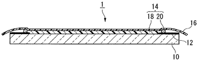
도 1 은 본 발명의 점착층이 형성된 투명 면재의 일례를 나타내는 단면도이다.
도 2 는 공정 (a) 의 양태의 일례를 나타내는 평면도이다.
도 3 은 공정 (a) 의 양태의 일례를 나타내는 단면도이다.
도 4 는 공정 (b) 의 양태의 일례를 나타내는 평면도이다.
도 5 는 공정 (b) 의 양태의 일례를 나타내는 단면도이다.
도 6 은 공정 (c) 의 양태의 일례를 나타내는 단면도이다.
도 7 은 본 발명의 표시 장치의 일례를 나타내는 단면도이다.
도 8 은 본 발명의 점착층이 형성된 투명 면재와 표시 패널을 첩합했을 때에 있어서의 표시 패널과 점착층의 계면에 있어서의 공극의 양태를 나타내는 사시도이다.
도 9 는 보호판과 표시 패널을 점착 시트를 개재하여 첩합했을 때에 있어서의 표시 패널과 점착 시트의 계면에 있어서의 공극의 양태를 나타내는 사시도이다.
도 10 은 보호판과 표시 패널을 점착 시트를 개재하여 첩합했을 때에 있어서의 표시 패널과 점착 시트의 계면에 있어서의 공극의 양태를 나타내는 사시도이다.BRIEF DESCRIPTION OF THE DRAWINGS It is sectional drawing which shows an example of the transparent face material in which the adhesion layer of this invention was formed.
2 is a plan view illustrating an example of an embodiment of the step (a).
3 is a cross-sectional view showing an example of the embodiment of the step (a).
4 is a plan view illustrating an example of an embodiment of the step (b).
5 is a cross-sectional view showing an example of the embodiment of the step (b).
6 is a cross-sectional view showing an example of the embodiment of the step (c).
7 is a cross-sectional view showing an example of the display device of the present invention.
It is a perspective view which shows the aspect of the space | gap in the interface of a display panel and an adhesion layer at the time of bonding together the transparent face material in which the adhesion layer of this invention was formed, and a display panel.
It is a perspective view which shows the aspect of the space | gap in the interface of a display panel and an adhesive sheet at the time of bonding a protective plate and a display panel together through an adhesive sheet.
It is a perspective view which shows the aspect of the space | gap in the interface of a display panel and an adhesive sheet at the time of bonding a protective plate and a display panel together through an adhesive sheet.
본 명세서에 있어서, 「투명」 이란, 광 투과성을 갖는 것을 의미하고, 「(메트)아크릴레이트」 는 아크릴레이트 또는 메타크릴레이트를 의미한다.In this specification, "transparence" means having light transmittance, and "(meth) acrylate" means an acrylate or a methacrylate.
<점착층이 형성된 투명 면재><Transparent face material with adhesive layer formed>
도 1 은 본 발명의 점착층이 형성된 투명 면재의 일례를 나타내는 단면도이다.BRIEF DESCRIPTION OF THE DRAWINGS It is sectional drawing which shows an example of the transparent face material in which the adhesion layer of this invention was formed.
점착층이 형성된 투명 면재 (1) 는, 보호판 (10) (투명 면재) 과, 보호판 (10) 의 표면의 주연부에 형성된 차광 인쇄부 (12) 와, 차광 인쇄부 (12) 가 형성된 측의 보호판 (10) 의 표면에 형성된 점착층 (14) 과, 점착층 (14) 의 표면을 덮는, 박리 가능한 보호 필름 (16) 을 갖는다.The
(보호판)(Protection board)
보호판 (10) 은, 후술하는 표시 패널의 화상 표시 측에 형성되어 표시 패널을 보호하는 것이다.The
보호판 (10) 으로는 유리판, 또는 투명 수지판을 들 수 있고, 표시 패널로부터의 출사광이나 반사광에 대하여 투명성이 높은 점은 물론, 내광성, 저복굴절성, 높은 평면 정밀도, 내표면 흠집성, 높은 기계적 강도를 갖는 점에서도, 유리판이 가장 바람직하다. 광경화성 수지 조성물의 경화를 위한 광을 충분히 투과시키는 점에서도 유리판이 바람직하다.Examples of the
유리판의 재료로는 소다 라임 유리 등의 유리 재료를 들 수 있고, 철분이 보다 낮고, 푸른 빛이 적은 고투과 유리 (백판 유리) 가 보다 바람직하다. 안전성을 높이기 위해서 표면재로서 강화 유리를 사용해도 된다. 특히 얇은 유리판을 사용하는 경우에는, 화학 강화를 실시한 유리판을 사용하는 것이 바람직하다.Glass materials, such as a soda-lime glass, are mentioned as a material of a glass plate, and high permeability glass (white glass) with less iron content and less blue light is more preferable. In order to improve safety, you may use tempered glass as a surface material. Especially when a thin glass plate is used, it is preferable to use a glass plate subjected to chemical strengthening.
투명 수지판의 재료로는 투명성이 높은 수지 재료 (폴리카보네이트, 폴리메틸메타크릴레이트 등) 를 들 수 있다.As a material of a transparent resin plate, resin materials (polycarbonate, polymethyl methacrylate, etc.) with high transparency are mentioned.
보호판 (10) 에는, 점착층 (14) 과의 계면 접착력을 향상시키기 위해서, 표면 처리를 실시해도 된다. 표면 처리의 방법으로는, 보호판 (10) 의 표면을 실란 커플링제로 처리하는 방법, 프레임 버너에 의한 산화염 (炎) 에 의해 산화 규소의 박막을 형성하는 방법 등을 들 수 있다.You may surface-treat the
보호판 (10) 에는, 표시 화상의 콘트라스트를 높이기 위해서, 점착층 (14) 이 형성된 측과는 반대측의 표면에 반사 방지층을 형성해도 된다. 반사 방지층은 보호판 (10) 의 표면에 무기 박막을 직접 형성하는 방법, 반사 방지층을 형성한 투명 수지 필름을 보호판 (10) 에 첩합하는 방법에 의해 형성할 수 있다.In the
또한, 목적에 따라, 보호판 (10) 의 일부 또는 전체를 착색하거나, 보호판 (10) 표면의 일부 또는 전체를 불투명 유리상으로 하여 광을 산란시키거나, 보호판 (10) 표면의 일부 또는 전체에 미세한 요철 등을 형성하여 투과광을 굴절 또는 반사시켜도 된다. 또한, 착색 필름, 광 산란 필름, 광 굴절 필름, 광 반사 필름 등을, 보호판 (10) 표면의 일부 또는 전체에 첩착해도 된다.In addition, depending on the purpose, part or all of the
보호판 (10) 의 형상은 통상적으로 직사각형이다.The shape of the
보호판 (10) 의 크기는 본 발명의 제조 방법이 비교적 대면적의 점착층이 형성된 투명 면재 (1) 의 제조에 특히 적합한 점에서, 텔레비전 수상기의 경우, 0.5 m×0.4 m 이상이 적당하고, 0.7 m×0.4 m 이상이 특히 바람직하다. 보호판 (10) 의 크기의 상한은 표시 패널의 크기로 정해지는 경우가 많다. 또한, 지나치게 큰 표시 장치는, 설치 등에 있어서의 취급이 곤란해지기 쉽다. 보호판 (10) 의 크기의 상한은 이들 제약으로부터, 통상적으로 2.5 m×1.5 m 정도이다.Since the manufacturing method of this invention is especially suitable for manufacture of the
보호판 (10) 의 두께는 기계적 강도, 투명성의 점에서, 유리판의 경우에는 통상적으로 0.5 ∼ 25 ㎜ 이다. 실내에서 사용하는 텔레비전 수상기, PC 용 디스플레이 등의 용도에서는, 표시 장치의 경량화의 점에서 1 ∼ 6 ㎜ 가 바람직하고, 옥외에 설치하는 공중 표시 용도로는 3 ∼ 20 ㎜ 가 바람직하다. 화학 강화 유리를 사용하는 경우에는, 유리의 두께는 강도의 점에서 0.5 ∼ 1.5 ㎜ 정도가 바람직하다. 투명 수지판의 경우에는 2 ∼ 10 ㎜ 가 바람직하다.In the case of a glass plate, the thickness of the
(차광 인쇄부)(Shading printing part)
차광 인쇄부 (12) 는, 후술하는 표시 패널의 화상 표시 영역 이외가 보호판 (10) 측으로부터 시인할 수 없도록 하여, 표시 패널에 접속되어 있는 배선 부재 등을 은폐하는 것이다. 차광 인쇄부 (12) 는 점착층 (14) 이 형성되는 측 또는 그 반대측의 표면에 형성할 수 있고, 차광 인쇄부 (12) 와 화상 표시 영역의 시차를 저감시키는 점에서는, 점착층 (14) 이 형성되는 측의 표면에 형성하는 것이 바람직하다. 보호판 (10) 이 유리판인 경우, 차광 인쇄부 (12) 에 흑색 안료를 함유하는 세라믹 인쇄를 사용하면 차광성이 높아 바람직하다. 차광 인쇄부가, 점착층이 형성된 측의 반대측에 형성되는 경우, 차광 인쇄부를 미리 형성한 투명 필름을 보호판에 첩합함으로써 형성할 수도 있다. 보호판에 첩합되는 면의 투명 필름의 주연부에 차광 인쇄부를 형성하고, 그 이면, 즉 표시 장치의 최표면에 반사 방지층을 형성한 필름을 보호판에 첩합해도 된다.The light-shielding
(점착층)(Adhesive layer)
점착층 (14) 은 보호판 (10) 의 표면을 따라 확산되는 층상부 (18) 와, 층상부 (18) 의 주연에 접하여 이것을 둘러싸는 언상부 (20) 를 갖는다.The
(층상부)(Floor)
층상부 (18) 는 액상의 층상부 형성용 경화성 수지 조성물 (이하, 제 1 조성물이라고 적는 경우도 있다) 을 경화시켜 이루어지는 투명 수지로 이루어지는 층이다.The
층상부 (18) 의 35 ℃ 에 있어서의 전단 탄성률은 0.5 ∼ 100 ㎪ 이고, 하한치는 0.8 ㎪ 가 바람직하다. 상한치는 25 ㎪ 가 바람직하고, 12 ㎪ 가 보다 바람직하다. 전단 탄성률이 0.5 ㎪ 이상이면, 층상부 (18) 의 형상을 유지할 수 있다. 또한, 층상부 (18) 의 두께가 비교적 두꺼운 경우라도, 층상부 (18) 전체에서 두께를 균일하게 유지할 수 있고, 점착층이 형성된 투명 면재 (1) 와 표시 패널을 첩합할 때에, 표시 패널과 점착층 (14) 의 계면에 공극이 잘 발생하지 않는다. 전단 탄성률이 100 ㎪ 이하이면, 감압 분위기하에서 표시 패널과 점착층이 형성된 투명 면재 (1) 를 첩합한 후, 이것을 대기압 분위기하로 되돌렸을 때에, 점착층 (14) 과 표시 패널의 계면에 발생한 공극이 단시간에 소실되고, 잔존하기 어렵다. 이것은, 층상부 (18) 를 형성하는 수지재의 분자 운동성이 비교적 높기 때문에, 감압 분위기하에서 표시 패널과 점착층이 형성된 투명 면재 (1) 를 첩합한 후, 이것을 대기압 분위기하로 되돌렸을 때에, 공극 내의 압력 (감압인 채) 과 층상부 (18) 에 가해지는 압력 (대기압) 의 차압에 의해 공극 (110) 의 체적이 감소하기 쉬워지기 때문인 것으로 추측된다.The shear modulus at 35 ° C. of the layered
층상부 (18) 의 35 ℃ 에 있어서의 전단 탄성률은, 레오 미터 (안톤 파르 (Anton paar) 사 제조, 모듈러 레오 미터 Physica MCR-301) 를 이용하고, 측정 스핀들과 투광성의 정판의 간극을 층상부 (18) 의 두께와 동일하게 하고, 그 간극에 미경화된 제 1 조성물을 배치하고, 경화에 필요한 열이나 광을 미경화된 제 1 조성물에 가하면서, 경화 과정의 전단 탄성률을 측정하고, 층상부 (18) 를 형성할 때의 경화 조건에 있어서의 계측치를 층상부 (18) 의 전단 탄성률로 하였다.The shear modulus at 35 ° C. of the
(언상부)(The upper part)
언상부 (20) 는 액상의 언상부 형성용 경화성 수지 조성물 (이하, 제 2 조성물이라고 적는 경우도 있다) 을 도포하고, 경화시켜 이루어지는 투명 수지로 이루어지는 부분이다. 표시 패널의 화상 표시 영역의 외측 영역이 비교적 좁기 때문에, 언상부 (20) 의 폭은 좁게 하는 것이 바람직하다. 언상부 (20) 의 폭은 0.5 ∼ 2 ㎜ 가 바람직하고, 0.8 ∼ 1.6 ㎜ 가 보다 바람직하다.The
층상부 (18) 의 두께는 0.03 ∼ 2 ㎜ 가 바람직하고, 0.1 ∼ 0.8 ㎜ 가 보다 바람직하다. 층상부 (18) 의 두께가 0.03 ㎜ 이상이면, 보호판 (10) 측으로부터의 외력에 의한 충격 등을 층상부 (18) 가 효과적으로 완충하여, 표시 패널을 보호할 수 있다. 또한, 본 발명의 표시 장치의 제조 방법에 있어서, 표시 패널과 점착층이 형성된 투명 면재 (1) 사이에 층상부 (18) 의 두께를 초과하지 않는 이물질이 혼입되어도, 층상부 (18) 의 두께가 크게 변화하지 않고, 광 투과 성능에 대한 영향이 적다. 층상부 (18) 의 두께가 2 ㎜ 이하이면, 층상부 (18) 에 공극이 잔류하기 어렵고, 또한 표시 장치의 전체 두께가 불필요하게 두꺼워지지 않는다.The thickness of the
언상부 (20) 의 두께는 표시 패널과 점착층이 형성된 투명 면재의 첩합시에 외부에 개방된 공극이 발생하기 어려운 점에서, 층상부 (18) 의 두께보다 약간 (차가 20 ㎛ 이하) 큰 것이 바람직하지만, 이에 한정되지 않는다.The thickness of the
즉, 언상부 (20) 의 두께가 층상부 (18) 의 두께보다 두꺼우면, 도 8 에 나타내는 바와 같이, 표시 패널 (50) 과 점착층이 형성된 투명 면재 (1) 를 첩합할 때에, 점착층 (14) 의 주연부에 있어서, 표시 패널 (50) 과 점착층 (14) 의 계면에 공극 (110) 이 잔존하고 있어도, 그 공극 (110) 이 언상부 (20) 에서 차단됨으로써, 공극 (110) 이 외부에 개방되지 않고, 독립적인 공극 (110) 이 된다. 따라서, 감압 분위기하에서 표시 패널 (50) 과 점착층이 형성된 투명 면재 (1) 를 첩합한 후, 이것을 대기압 분위기하로 되돌렸을 때에, 공극 (110) 내의 압력 (감압인 채) 과 점착층 (14) 에 가해지는 압력 (대기압) 의 차압에 의해 공극 (110) 의 체적이 감소하고, 공극 (110) 은 소실된다.That is, when the thickness of the
층상부 (18) 및 언상부 (20) 의 각 부의 두께는, 보호판 (10) 의 표면에 공급되는 액상의 제 1 조성물 또는 제 2 조성물의 공급량과, 각각의 경화시의 수축률에 따라 조정할 수 있다.The thickness of each part of the
본 발명에서 사용되는 제 1 조성물 (층상부 형성용 경화성 수지 조성물) 의 중합 수축률은, 비경화성 올리고머의 함유량이 많아질수록 낮아진다. 이 때문에, 제 2 조성물의 중합 수축률 쪽이 상대적으로 높아져, 언상부 (20) 의 두께가 층상부 (18) 의 두께보다 작아지는 경우가 있다.The polymerization shrinkage rate of the first composition (curable resin composition for forming a layer) used in the present invention is lowered as the content of the non-curable oligomer increases. For this reason, the polymerization shrinkage side of a 2nd composition may become relatively high, and the thickness of the
언상부 (20) 의 두께가 층상부 (18) 와 동등하거나 또는 층상부 (18) 보다 작은 것에서 기인하여, 다른 면재와 점착층의 계면에 외부에 개방된 공극이 발생하는 경우, 이것을 개선하는 방법으로는, 층상부 (18) 및 언상부 (20) 를 경화시킬 때에, 하면에 단차를 형성한 지지 면재 (36) 를 얹어, 경화 후의 층상부 (18) 의 상면이 언상부 (20) 의 상면보다 낮아지도록 하는 방법, 제 2 조성물을 언상으로 형성할 때에, 경화 후의 두께보다 커지도록 보호판 (10) 의 표면에 공급하고, 나아가, 제 1 조성물의 공급 전에, 제 2 조성물을 경화시키는 광을 단시간 조사함으로써 제 2 조성물을 부분적으로 경화 또는 증점시켜, 언상부의 두께를 확보하는 방법 등이 있다. 제 1 조성물의 공급 전에 제 2 조성물을 부분적으로 경화시키는 경우에는, 언상부 (20) 의 선 폭을 가늘게 형성하면, 후술하는 지지 면재와의 적층시에 언상부를 변형시키기 쉽기 때문에 바람직하다.When the thickness of the
(지지 면재)(Supporting face material)
후술하는 본 발명의 제조 방법에 있어서 사용하는, 도 6 에 나타내는 지지 면재 (36) 는, 유리판, 수지판 등의 투명 면재이다. 비교적 대면적의 지지 면재 (36) 를 사용하는 경우에는, 지지 면재 (36) 의 휨, 굽힘 등이 있으면 점착층 (14) 의 표면 성상에 악영향을 미칠 우려가 있기 때문에, 보다 강성이 높은 유리판을 사용하는 것이 바람직하다. 또한, 유리판을 지지 면재 (36) 로서 사용하는 경우의 유리판의 두께는 0.5 ∼ 10 ㎜ 가 바람직하다. 두께가 0.5 ㎜ 보다 얇으면 휨이나 굽힘이 발생하기 쉽고, 10 ㎜ 보다 두꺼우면 지지 면재 (36) 의 질량이 불필요하게 커져, 점착층 (14) 의 경화 전의 적층물을 이동시킬 때에 지지 면재 (36) 가 어긋나기 쉬워질 우려가 있다. 특히 바람직하게는 1.0 ∼ 5.0 ㎜ 이다.The
(보호 필름)(Protective film)
보호 필름 (16) 에는, 점착층 (14) 과 강고하게 밀착하지 않을 것, 그리고 후술하는 본 발명의 제조 방법에 있어서 지지 면재 (36) 에 첩착할 수 있을 것이 요구된다. 따라서, 보호 필름 (16) 으로는 폴리에틸렌, 폴리프로필렌, 불소계 수지 등의 밀착성이 비교적 낮은 기재 필름의 편면이 점착면이 된 자기 점착성 보호 필름이 바람직하다.The
보호 필름 (16) 의 점착면의 점착력은 아크릴판에 대한 박리 속도 300 ㎜/분에서의 180 도 박리 시험에 있어서의 50 ㎜ 폭의 시험체로 0.01 ∼ 0.1 N 이 바람직하고, 0.02 ∼ 0.06 N 이 더욱 바람직하다. 점착력이 0.01 N 이상 있으면 지지 면재 (36) 에 대한 첩착이 가능하고, 0.1 N 이하이면 지지 면재 (36) 로부터 보호 필름 (16) 을 박리시키는 것이 용이하다.As for the adhesive force of the adhesive face of the
보호 필름 (16) 의 바람직한 두께는, 사용하는 수지에 따라 상이한데, 폴리에틸렌, 폴리프로필렌 등의 비교적 유연한 필름을 사용하는 경우에는 0.04 ∼ 0.2 ㎜ 가 바람직하고, 0.06 ∼ 0.1 ㎜ 가 더욱 바람직하다. 0.04 ㎜ 이상이면 점착층 (14) 으로부터 보호 필름 (16) 을 박리할 때에 보호 필름 (16) 의 변형을 억제할 수 있고, 0.2 ㎜ 이하이면 박리시에 보호 필름 (16) 이 구부러지기 쉬워 박리시키는 것이 용이하다.Although the preferable thickness of the
또한, 보호 필름 (16) 의 점착면과는 반대측의 이면에 배면층을 형성하고, 점착층 (14) 으로부터의 박리를 더욱 용이하게 할 수도 있다. 배면층에도, 폴리에틸렌, 폴리프로필렌, 불소계 수지 등의 밀착성이 비교적 낮은 필름을 사용하는 것이 바람직하다. 더욱 박리를 용이하게 하기 위해서, 점착층 (14) 에 악영향을 주지 않는 범위에서, 실리콘 등의 이형제를 도포할 수도 있다.Moreover, a back layer can be formed in the back surface on the opposite side to the adhesive face of the
지지 면재 (36) 에 대한 보호 필름 (16) 의 첩착은, 롤상의 권물로서 공급되는 보호 필름 (16) 을, 고무 롤 등을 이용하여 지지 면재 (36) 에 첩합시킴으로써 실시된다. 이 때, 지지 면재 (36) 와 보호 필름 (16) 의 점착면 사이에 공극이 발생하지 않도록, 고무 롤을 지지 면재 (36) 에 누르거나, 감압 공간에서 첩합시킬 수 있다. 점착층 (14) 으로부터의 박리시에 보호 필름 (16) 의 단부를 담지하기 쉽도록, 지지 면재 (36) 보다 한 사이즈 큰 보호 필름 (16) 을 사용하는 것이 바람직하다.The sticking of the
(다른 형태)(Other forms)
또한, 도시예의 점착층이 형성된 투명 면재 (1) 는, 투명 면재가 표시 장치의 보호판인 예지만, 본 발명의 점착층이 형성된 투명 면재는, 도시예의 것에 한정은 되지 않고, 투명 면재의 적어도 일방의 표면에 특정한 점착층이 형성된 것이면 된다.In addition, although the
예를 들어, 본 발명의 점착층이 형성된 투명 면재는, 투명 면재의 양면에 특정한 점착층이 형성된 것이어도 된다.For example, the transparent face material in which the adhesion layer of this invention was formed may be the one in which specific adhesion layers were formed on both surfaces of a transparent face material.
또한, 투명 면재 (보호판) 와 특정한 점착층 사이에, 편광 수단 (필름상의 흡수형 편광자, 와이어 그리드형 편광자 등) 이나 광 변조 수단 (1/4 파장판 등의 위상차 필름, 스트라이프상으로 패턴 가공된 위상차 필름 등) 이 형성된 것이어도 된다.Further, between the transparent face plate (protective plate) and the specific adhesive layer, pattern processing is performed in polarized means (absorption type polarizer on film, wire grid type polarizer, etc.) or light modulation means (retardation film such as quarter wave plate, stripe shape). Retardation film, etc.) may be formed.
<점착층이 형성된 투명 면재의 제조 방법><Method for Producing Transparent Face Material with Adhesive Layer>
본 발명의 점착층이 형성된 투명 면재의 제조 방법은 하기의 공정 (a) ∼ (e) 를 갖는 방법이다.The manufacturing method of the transparent face material with an adhesion layer of this invention is a method which has the following process (a)-(e).
(a) 투명 면재 표면의 주연부에, 액상의 제 2 조성물을 도포하여 미경화된 언상부를 형성하는 공정.(a) Process of apply | coating a liquid 2nd composition to the periphery of the surface of a transparent face material, and forming an uncured frozen part.
(b) 미경화된 언상부로 둘러싸인 영역에, 액상의 제 1 조성물을 공급하는 공정.(b) Process of supplying a liquid 1st composition to the area | region enclosed by the uncured frozen part.
(c) 100 ㎩ 이하의 감압 분위기하에서, 제 1 조성물 상에, 보호 필름이 첩착된 지지 면재를, 보호 필름이 제 1 조성물에 접하도록 겹쳐서, 투명 면재, 보호 필름 및 미경화된 언상부로 제 1 조성물로 이루어지는 미경화된 층상부가 밀봉된 적층물을 얻는 공정.(c) Under a reduced pressure atmosphere of 100 Pa or less, the support face material with the protective film adhered on the first composition is laminated so that the protective film is in contact with the first composition, and the transparent face material, the protective film, and the uncured hard portion are prepared. The process of obtaining the laminated body by which the uncured layered part which consists of 1 composition was sealed.
(d) 50 ㎪ 이상의 압력 분위기하에 적층물을 둔 상태로, 미경화된 층상부 및 미경화된 언상부를 경화시켜, 층상부 및 언상부를 갖는 점착층을 형성하는 공정.(d) Process of hardening an uncured layered part and an uncured frozen upper part in the state which laminated | stacked it in the pressure atmosphere of 50 Pa or more, and forming the adhesion layer which has a layered part and a frozen part.
(e) 지지 면재를 보호 필름으로부터 박리하는 공정.(e) Process of peeling a support face material from a protective film.
본 발명의 제조 방법은, 감압 분위기하에서 투명 면재와, 지지 면재에 첩착된 보호 필름 사이에 액상의 제 1 조성물을 봉입하고, 대기압 분위기 하 등의 높은 압력 분위기하에서, 봉입되어 있는 제 1 조성물을 경화시켜 층상부를 형성하는 방법이다. 감압 하에 있어서의 제 1 조성물의 봉입은, 투명 면재와, 지지 면재에 첩착된 보호 필름의 간극이 좁고 넓은 공간에 층상부 형성용 경화성 수지를 주입하는 방법이 아니라, 투명 면재의 대략 전체면에 제 1 조성물을 공급하고, 그 후, 지지 면재에 첩착된 보호 필름을 겹쳐서 투명 면재와, 지지 면재에 첩착된 보호 필름 사이에 제 1 조성물을 봉입하는 방법이다.The manufacturing method of this invention encloses a liquid 1st composition between a transparent face material and a protective film stuck to a support face material in a reduced pressure atmosphere, and hardens the 1st composition enclosed in high pressure atmosphere, such as under atmospheric pressure atmosphere. To form a layered portion. The sealing of the 1st composition under reduced pressure is not a method of inject | pouring curable resin for layer part formation into the space where the space | interval of a transparent face material and the protective film stuck to the support face material is narrow, but to the substantially whole surface of a transparent face material. It is a method of supplying 1 composition, and after that, the protective film stuck to the support face material is piled up, and the 1st composition is enclosed between a transparent face material and the protective film stuck to a support face material.
감압하에 있어서의 액상의 경화성 수지 조성물의 봉입, 및 대기압 분위기하에 있어서의 경화성 수지 조성물의 경화에 의한 투명 적층체의 제조 방법의 일례는 공지이다. 예를 들어, 국제 공개 제2008/81838호 팜플렛, 국제 공개 제2009/16943호 팜플렛에 투명 적층체의 제조 방법 및 그 제조 방법에 사용되는 경화성 수지 조성물이 기재되어 있고, 본 명세서 중에 도입된다.An example of the manufacturing method of the transparent laminated body by sealing of the liquid curable resin composition under reduced pressure, and hardening of curable resin composition in atmospheric pressure atmosphere is well-known. For example, the international publication 2008/81838 pamphlet and the international publication 2009/16943 pamphlet describe the manufacturing method of a transparent laminated body, and curable resin composition used for the manufacturing method, and are introduce | transduced in this specification.
(공정 (a))(Step (a))
먼저, 투명 면재 표면의 주연부에, 액상의 제 2 조성물을 도포하여 미경화된 언상부를 형성한다. 도포는 인쇄기, 디스펜서 등을 이용하여 실시된다.First, the liquid 2nd composition is apply | coated to the peripheral part of the surface of a transparent face material, and an unhardened frozen image part is formed. Coating is performed using a printing press, a dispenser, etc.
공정 (d) 에서 경화되기 전의 언상부는, 후술하는 공정 (c) 에 있어서, 미경화된 언상부와 투명 면재의 계면, 및 미경화된 언상부와 보호 필름의 계면으로부터 액상의 제 1 조성물이 누출되지 않을 정도 이상의 계면 밀착력, 및 형상을 유지할 수 있을 정도의 단단함이 있으면 된다. 예를 들어, 언상부는 점도가 높은 제 2 조성물을 이용하여 형성하는 것이 바람직하다.In the step (c) described later, in the step (c), the frozen top portion before curing is a liquid first composition from the interface between the uncured frozen top portion and the transparent face material and the interface between the uncured frozen top portion and the protective film. What is necessary is just to have the interface adhesive force more than the leaking degree, and the rigidity enough to maintain a shape. For example, it is preferable to form a frozen portion using the 2nd composition with high viscosity.
혹은, 층상부의 형성에 사용하는 제 1 조성물과 동일한 조성물을, 투명 면재의 표면의 주연부에 도포하여 반경화시킨 것을, 공정 (d) 에서 경화되기 전의 언상부로 해도 된다.Or what apply | coated and semi-hardened the composition similar to the 1st composition used for formation of a layered part to the periphery of the surface of a transparent face material may be made into the frozen part before hardening in a process (d).
제 2 조성물의 점도는 500 ∼ 3000 ㎩·s 가 바람직하고, 800 ∼ 2500 ㎩·s 가 보다 바람직하고, 1000 ∼ 2000 ㎩·s 가 더욱 바람직하다. 점도가 500 ㎩·s 이상이면, 미경화된 언상부의 형상을 비교적 장시간 유지할 수 있고, 미경화된 언상부의 높이를 충분히 유지할 수 있다. 점도가 3000 ㎩·s 이하이면, 미경화된 언상부를 도포에 의해 형성할 수 있다.500-3000 Pa.s is preferable, as for the viscosity of a 2nd composition, 800-2500 Pa.s is more preferable, and 1000-2000 Pa.s is more preferable. When the viscosity is 500 Pa · s or more, the shape of the uncured frozen portion can be maintained for a relatively long time, and the height of the uncured frozen portion can be sufficiently maintained. If the viscosity is 3000 Pa · s or less, the uncured frozen portion can be formed by coating.
제 2 조성물의 점도는 25 ℃ 에 있어서 E 형 점도계를 이용하여 측정한다.The viscosity of a 2nd composition is measured using an E-type viscosity meter at 25 degreeC.
또한, 투명 면재와 표시 패널의 간격을 유지하기 위해서, 소정의 입자경의 스페이서 입자를 제 2 조성물에 배합해도 된다.In addition, in order to maintain the space | interval of a transparent face material and a display panel, you may mix | blend the spacer particle of a predetermined particle diameter with a 2nd composition.
액상의 제 2 조성물의 도포 후에, 제 2 조성물을 경화시키는 광을 단시간 조사함으로써 제 2 조성물을 부분적으로 경화 또는 증점시키면, 언상부의 형상을 더욱 유지할 수 있어 바람직하다.After application | coating of a liquid 2nd composition, if the 2nd composition is partially hardened or thickened by irradiating the light which hardens a 2nd composition for a short time, the shape of a frozen part can be further maintained and it is preferable.
제 2 조성물은 광경화성 수지 조성물이어도 되고, 열경화성 수지 조성물이어도 된다. 제 2 조성물로는, 저온에서 경화시킬 수 있고, 또한 경화 속도가 빠른 점에서, 경화성 화합물 및 광중합 개시제 (C) 를 함유하는 광경화성 수지 조성물이 바람직하다. 또한, 경화에는 높은 온도를 필요로 하지 않는 점에서, 고온에 의한 표시 패널의 손상의 우려도 적다.The second composition may be a photocurable resin composition or a thermosetting resin composition. As a 2nd composition, since it can harden | cure at low temperature and a hardening rate is fast, the photocurable resin composition containing a curable compound and a photoinitiator (C) is preferable. Moreover, since hardening does not require high temperature, there is little possibility of damaging the display panel by high temperature.
혹은, 층상부의 형성에 사용하는 제 1 조성물과 동일한 조성물을, 투명 면재의 표면의 주연부에 도포하여 반경화시킨 것을, 공정 (d) 에서 경화되기 전의 언상부로 해도 된다.Or what apply | coated and semi-hardened the composition similar to the 1st composition used for formation of a layered part to the periphery of the surface of a transparent face material may be made into the frozen part before hardening in a process (d).
본 발명에 있어서, 제 2 조성물로서 바람직한 언상부 형성용 광경화성 수지 조성물에 대해 설명한다.In the present invention, a photocurable resin composition for forming an upper portion, which is preferable as the second composition, will be described.
[언상부 형성용 광경화성 수지 조성물][Photocurable Resin Composition for Formation of Upper Section]
언상부 형성용 광경화성 수지 조성물은, 광경화성의 경화성 화합물 (I) 및 광중합 개시제 (C1) 을 함유하는 액상의 조성물이다.The photocurable resin composition for annealing part formation is a liquid composition containing photocurable curable compound (I) and a photoinitiator (C1).
(경화성 화합물 (I))(Curable Compound (I))
경화성 화합물 (I) 은, 언상부 형성용 광경화성 수지 조성물의 점도를 상기 범위로 조정하기 쉬운 점에서, 경화성기를 갖고, 또한 수평균 분자량이 30000 ∼ 100000 인 올리고머 (A) 의 1 종 이상과, 경화성기를 갖고, 또한 분자량이 125 ∼ 600 인 모노머 (B) 의 1 종 이상을 함유하는 것이 바람직하다.Since the curable compound (I) is easy to adjust the viscosity of the photocurable resin composition for forming an upper portion into the above range, at least one of oligomers (A) having a curable group and having a number average molecular weight of 30000 to 100000, It is preferable to have a curable group and to contain 1 or more types of monomers (B) whose molecular weight is 125-600.
올리고머 (A) 또는 모노머 (B) 의 경화성기로는, 부가 중합성의 불포화기 (아크릴로일옥시기, 메타크릴로일옥시기 등), 불포화기와 티올기의 조합 등을 들 수 있고, 경화 속도가 빠른 점 및 투명성이 높은 언상부가 얻어지는 점에서, 아크릴로일옥시기 및 메타크릴로일옥시기에서 선택되는 기가 바람직하다.Examples of the curable group of the oligomer (A) or the monomer (B) include an addition polymerizable unsaturated group (acryloyloxy group, methacryloyloxy group, etc.), a combination of an unsaturated group and a thiol group, and the like. And the point selected from the acryloyloxy group and the methacryloyloxy group are preferable at the point from which the frozen part with high transparency is obtained.
올리고머 (A) 에 있어서의 경화성기와, 모노머 (B) 에 있어서의 경화성기는 서로 동일해도 되고, 상이해도 된다. 비교적 고분자량의 올리고머 (A) 에 있어서의 경화성기는, 비교적 저분자량의 모노머 (B) 에 있어서의 경화성기보다 반응성이 낮아지기 쉽기 때문에, 모노머 (B) 의 경화가 먼저 진행되어, 급격하게 조성물 전체의 점성이 높아져 경화 반응이 불균질해질 우려가 있다. 양자의 경화성기의 반응성의 차를 작게 하고, 균질의 언상부를 얻기 위해서, 올리고머 (A) 의 경화성기를 비교적 반응성이 높은 아크릴로일옥시기로 하고, 모노머 (B) 의 경화성기를 비교적 반응성이 낮은 메타크릴로일옥시기로 할 수도 있다.The curable group in an oligomer (A) and the curable group in a monomer (B) may mutually be same or different. Since the reactivity of a curable group in a comparatively high molecular weight oligomer (A) tends to become less reactive than the curable group in a comparatively low molecular weight monomer (B), hardening of a monomer (B) advances first and abruptly of the whole composition Viscosity becomes high and there exists a possibility that a hardening reaction may become heterogeneous. In order to make the difference of the reactivity of both curable groups small, and to obtain a homogeneous frozen part, the curable group of an oligomer (A) is made into the highly reactive acryloyloxy group, and the curable group of the monomer (B) has a relatively low meta It may also be referred to as a cryloyloxy group.
올리고머 (A) 의 수평균 분자량은 30000 ∼ 100000 이고, 40000 ∼ 80000 이 바람직하고, 50000 ∼ 65000 이 보다 바람직하다. 올리고머 (A) 의 수평균 분자량이 그 범위이면, 언상부 형성용 광경화성 수지 조성물의 점도를 상기 범위로 조정하기 쉽다.The number average molecular weights of an oligomer (A) are 30000-100000, 40000-80000 are preferable and 50000-65000 are more preferable. If the number average molecular weight of an oligomer (A) is the range, it is easy to adjust the viscosity of the photocurable resin composition for annealing part formation to the said range.
올리고머 (A) 의 수평균 분자량은, GPC (겔 침투 크로마토그래피) 의 측정에 의해 얻어진, 폴리스티렌 환산의 수평균 분자량이다. 또한, GPC 의 측정에 있어서, 미반응된 저분자량 성분 (모노머 등) 의 피크가 나타나는 경우에는, 그 피크를 제외하고 수평균 분자량을 구한다.The number average molecular weight of an oligomer (A) is the number average molecular weight of polystyrene conversion obtained by the measurement of GPC (gel permeation chromatography). In addition, in the measurement of GPC, when the peak of the unreacted low molecular weight component (monomer etc.) appears, the number average molecular weight is calculated | required except the peak.
모노머 (B) 의 분자량은 125 ∼ 600 이고, 140 ∼ 400 이 바람직하고, 150 ∼ 350 이 보다 바람직하다. 모노머 (B) 의 분자량이 125 이상이면, 후술하는 감압 적층 방법에 의해 표시 장치를 제조할 때의 모노머 (B) 의 휘발이 억제된다. 모노머 (B) 의 분자량이 600 이하이면, 고분자량의 올리고머 (A) 에 대한 모노머 (B) 의 용해성을 높일 수 있고, 언상부 형성용 광경화성 수지 조성물로서의 점도 조정을 바람직하게 실시할 수 있다.The molecular weight of monomer (B) is 125-600, 140-400 are preferable and 150-350 are more preferable. If the molecular weight of monomer (B) is 125 or more, volatilization of monomer (B) at the time of manufacturing a display apparatus by the pressure reduction lamination method mentioned later is suppressed. When the molecular weight of a monomer (B) is 600 or less, the solubility of the monomer (B) with respect to a high molecular weight oligomer (A) can be improved, and viscosity adjustment as a photocurable resin composition for frost-form formation can be performed preferably.
(올리고머 (A))(Oligomer (A))
올리고머 (A) 로는, 언상부 형성용 광경화성 수지 조성물의 경화성, 언상부의 기계적 특성의 점에서, 경화성기를 1 분자당 평균 1.8 ∼ 4 개 갖는 것이 바람직하다.As an oligomer (A), it is preferable to have an average of 1.8-4 hardenable groups per molecule from the point of sclerosis | hardenability of the photocurable resin composition for frozen part formation, and the mechanical characteristic of a frozen part.
올리고머 (A) 로는, 우레탄 결합을 갖는 우레탄 올리고머, 폴리옥시알킬렌폴리올의 폴리(메트)아크릴레이트, 폴리에스테르폴리올의 폴리(메트)아크릴레이트 등을 들 수 있다.As an oligomer (A), the urethane oligomer which has a urethane bond, the poly (meth) acrylate of polyoxyalkylene polyol, the poly (meth) acrylate of polyester polyol, etc. are mentioned.
우레탄 사슬의 분자 설계 등에 의해 경화 후의 수지의 기계적 특성, 면재와의 밀착성 등을 폭넓게 조정할 수 있는 점에서, 폴리올 및 폴리이소시아네이트를 원료에 이용하여 합성된 우레탄 올리고머가 바람직하고, 후술하는 우레탄 올리고머 (A1) 이 보다 바람직하다. 폴리올은 폴리옥시알킬렌폴리올이 보다 바람직하다.The urethane oligomer synthesize | combined using polyol and polyisocyanate as a raw material is preferable at the point which can adjust the mechanical property of resin after hardening, adhesiveness with a face material, etc. widely by molecular design of a urethane chain, etc., The urethane oligomer mentioned later (A1) ) Is more preferred. The polyol is more preferably a polyoxyalkylene polyol.
(우레탄 올리고머 (A1))(Urethane oligomer (A1))
수평균 분자량이 30000 ∼ 100000 의 범위인 우레탄 올리고머 (A1) 은, 고점도가 되기 때문에, 통상적인 방법으로는 잘 합성되지 않고, 합성할 수 있었다고 하더라도 모노머 (B) 와의 혼합이 어렵다.Since the urethane oligomer (A1) having a number average molecular weight in the range of 30000 to 100000 has a high viscosity, it is not well synthesized by a conventional method, and even though it can be synthesized, mixing with the monomer (B) is difficult.
그 때문에, 우레탄 올리고머 (A1) 을, 모노머 (B) (하기 모노머 (B1) 및 (B2)) 를 사용하는 합성 방법으로 합성한 후, 얻어진 생성물을 그대로 언상부 형성용 광경화성 수지 조성물로서 사용하거나, 또는 얻어진 생성물을 추가로 모노머 (B) (하기 모노머 (B1), 모노머 (B3) 등) 로 희석하여 언상부 형성용 광경화성 수지 조성물로서 사용하는 것이 바람직하다.Therefore, after synthesize | combining a urethane oligomer (A1) by the synthesis | combining method using a monomer (B) (following monomers (B1) and (B2)), the obtained product is used as it is as a photocurable resin composition for forming an upper part, or Or it is preferable to further dilute the obtained product with monomer (B) (following monomer (B1), monomer (B3), etc.), and to use it as a photocurable resin composition for frozen-bed formation.
(1) 모노머 (B1) : 모노머 (B) 중, 경화성기를 갖고, 또한 이소시아네이트기와 반응하는 기를 갖지 않는 모노머.(1) Monomer (B1): A monomer which has a curable group and does not have a group which reacts with an isocyanate group in the monomer (B).
(2) 모노머 (B2) : 모노머 (B) 중, 경화성기를 갖고, 또한 이소시아네이트기와 반응하는 기를 갖는 모노머.(2) Monomer (B2): A monomer which has a curable group and reacts with an isocyanate group in the monomer (B).
(3) 모노머 (B3) : 모노머 (B) 중, 경화성기를 갖고, 또한 수산기를 갖는 모노머.(3) Monomer (B3): The monomer which has a curable group and also has a hydroxyl group among monomers (B).
우레탄 올리고머 (A1) 의 합성 방법 : Synthesis method of urethane oligomer (A1):
희석제로서 모노머 (B1) 의 존재하, 폴리올과 폴리이소시아네이트를 반응시켜 이소시아네이트기를 갖는 프리폴리머를 얻은 후, 그 프리폴리머의 이소시아네이트기에, 모노머 (B2) 를 반응시키는 방법.A method in which a monomer (B2) is reacted with an isocyanate group of the prepolymer after obtaining a prepolymer having an isocyanate group by reacting a polyol and a polyisocyanate in the presence of a monomer (B1) as a diluent.
폴리올, 폴리이소시아네이트로는, 공지된 화합물, 예를 들어, 국제 공개 제2009/016943호 팜플렛에 기재된 우레탄계 올리고머 (a) 의 원료로서 기재된, 폴리올 (i), 디이소시아네이트 (ii) 등을 들 수 있고, 본 명세서에 도입된다.Examples of the polyol and polyisocyanate include polyols (i) and diisocyanates (ii), which are known compounds, for example, as raw materials of the urethane oligomer (a) described in International Publication No. 2009/016943 pamphlet. Introduced herein.
폴리올 (i) 로는 폴리옥시에틸렌글리콜, 폴리옥시프로필렌디올 등의 폴리옥시알킬렌폴리올이나, 폴리에스테르폴리올, 폴리카보네이트폴리올 등을 들 수 있다. 이들 중에서도, 폴리옥시알킬렌폴리올이 바람직하고, 특히 폴리옥시프로필렌폴리올이 바람직하다. 또한, 폴리옥시프로필렌폴리올의 옥시프로필렌기의 일부를 옥시에틸렌기로 치환하면, 언상부 형성용 광경화성 수지 조성물의 다른 성분과의 상용성을 높일 수 있어 더욱 바람직하다.As polyol (i), polyoxyalkylene polyol, such as polyoxyethylene glycol and polyoxypropylene diol, polyester polyol, polycarbonate polyol, etc. are mentioned. Among these, polyoxyalkylene polyols are preferable, and polyoxypropylene polyol is particularly preferable. In addition, when a part of the oxypropylene group of the polyoxypropylene polyol is substituted with an oxyethylene group, compatibility with other components of the photocurable resin composition for forming an upper portion can be enhanced, which is more preferable.
디이소시아네이트 (ii) 로는 지방족 디이소시아네이트, 지환식의 디이소시아네이트 및 무황 변성 방향족 디이소시아네이트에서 선택되는 디이소시아네이트가 바람직하다. 그 중, 지방족 폴리이소시아네이트의 예로는, 헥사메틸렌디이소시아네이트, 2,2,4-트리메틸-헥사메틸렌디이소시아네이트, 2,4,4-트리메틸-헥사메틸렌디이소시아네이트 등을 들 수 있다. 지환식 폴리이소시아네이트의 예로는, 이소포론디이소시아네이트, 메틸렌비스(4-시클로헥실이소시아네이트) 등을 들 수 있다. 무황 변성 방향족 디이소시아네이트로는 자일릴렌디이소시아네이트 등을 들 수 있다. 이들은 1 종을 단독으로 사용해도 되고, 2 종류 이상을 병용해도 된다.As diisocyanate (ii), diisocyanate chosen from aliphatic diisocyanate, alicyclic diisocyanate, and sulfur-free modified aromatic diisocyanate is preferable. Among them, examples of the aliphatic polyisocyanate include hexamethylene diisocyanate, 2,2,4-trimethyl-hexamethylene diisocyanate, 2,4,4-trimethyl-hexamethylene diisocyanate and the like. Examples of the alicyclic polyisocyanate include isophorone diisocyanate, methylenebis (4-cyclohexyl isocyanate), and the like. Examples of the non-sulfur-modified aromatic diisocyanate include xylylene diisocyanate and the like. These may be used singly or in combination of two or more.
모노머 (B1) 로는 탄소수 8 ∼ 22 의 알킬기를 갖는 알킬(메트)아크릴레이트 (n-도데실(메트)아크릴레이트, n-옥타데실(메트)아크릴레이트, n-베헤닐(메트)아크릴레이트 등), 지환식 탄화수소기를 갖는 (메트)아크릴레이트 (이소보르닐(메트)아크릴레이트, 아다만틸(메트)아크릴레이트 등) 을 들 수 있다.Examples of the monomer (B1) include alkyl (meth) acrylates having an alkyl group having 8 to 22 carbon atoms (n-dodecyl (meth) acrylate, n-octadecyl (meth) acrylate, n-behenyl (meth) acrylate, etc.). And (meth) acrylate (isobornyl (meth) acrylate, adamantyl (meth) acrylate, etc.) which have alicyclic hydrocarbon group are mentioned.
모노머 (B2) 로는 활성 수소 (수산기, 아미노기 등) 및 경화성기를 갖는 모노머를 들 수 있고, 구체적으로는, 탄소수 2 ∼ 6 의 하이드록시알킬기를 갖는 하이드록시알킬(메트)아크릴레이트 (2-하이드록시에틸(메트)아크릴레이트, 2-하이드록시프로필(메트)아크릴레이트, 2-하이드록시부틸(메트)아크릴레이트, 4-하이드록시부틸(메트)아크릴레이트 등) 등을 들 수 있고, 탄소수 2 ∼ 4 의 하이드록시알킬기를 갖는 하이드록시알킬아크릴레이트가 바람직하다.As a monomer (B2), the monomer which has active hydrogen (hydroxyl group, an amino group, etc.) and a curable group is mentioned, Specifically, the hydroxyalkyl (meth) acrylate (2-hydroxy which has a C2-C6 hydroxyalkyl group) Ethyl (meth) acrylate, 2-hydroxypropyl (meth) acrylate, 2-hydroxybutyl (meth) acrylate, 4-hydroxybutyl (meth) acrylate, etc.); The hydroxyalkyl acrylate which has a hydroxyalkyl group of 4 is preferable.
(모노머 (B))(Monomer (B))
모노머 (B) 는 언상부 형성용 광경화성 수지 조성물의 경화성, 언상부의 기계적 특성의 점에서, 경화성기를 1 분자당 1 ∼ 3 개 갖는 것이 바람직하다.It is preferable that a monomer (B) has 1-3 curable groups per molecule from the point of sclerosis | hardenability of the photocurable resin composition for frozen part formation, and the mechanical property of a frozen part.
언상부 형성용 광경화성 수지 조성물은, 모노머 (B) 로서, 상기 서술한 우레탄 올리고머 (A1) 의 합성 방법에 있어서 희석제로서 사용한 모노머 (B1) 을 함유하고 있어도 된다. 또한, 모노머 (B) 로서, 상기 서술한 우레탄 올리고머 (A1) 의 합성 방법에 사용한 미반응된 모노머 (B2) 를 함유하고 있어도 된다.The photocurable resin composition for annealing part formation may contain the monomer (B1) used as a diluent in the synthesis method of the urethane oligomer (A1) mentioned above as a monomer (B). Moreover, as a monomer (B), you may contain the unreacted monomer (B2) used for the synthesis | combining method of the urethane oligomer (A1) mentioned above.
모노머 (B) 는, 투명 면재와 언상부의 밀착성이나 후술하는 각종 첨가제의 용해성의 점에서, 수산기를 갖는 모노머 (B3) 을 함유하는 것이 바람직하다.It is preferable that a monomer (B) contains the monomer (B3) which has a hydroxyl group from the adhesive point of a transparent face material and a frozen part, and the solubility of the various additives mentioned later.
수산기를 갖는 모노머 (B3) 으로는 수산기수 1 ∼ 2, 탄소수 3 ∼ 8 의 하이드록시알킬기를 갖는 하이드록시메타크릴레이트 (2-하이드록시프로필메타크릴레이트, 2-하이드록시부틸메타크릴레이트, 4-하이드록시부틸메타크릴레이트, 6-하이드록시헥실메타크릴레이트 등) 가 바람직하고, 2-하이드록시부틸메타크릴레이트가 특히 바람직하다.Examples of the monomer (B3) having a hydroxyl group include hydroxy methacrylate (2-hydroxypropyl methacrylate and 2-hydroxybutyl methacrylate, 4) having a hydroxyalkyl group having 1 to 2 hydroxyl groups and 3 to 8 carbon atoms. -Hydroxybutyl methacrylate, 6-hydroxyhexyl methacrylate, etc.) are preferable, and 2-hydroxybutyl methacrylate is especially preferable.
언상부 형성용 광경화성 수지 조성물에 있어서의 모노머 (B) 의 함유 비율은, 경화성 화합물 (I) 의 전체 (100 질량%), 즉 올리고머 (A) 와 모노머 (B) 의 합계 (100 질량%) 중 15 ∼ 50 질량% 가 바람직하고, 20 ∼ 45 질량% 가 보다 바람직하고, 25 ∼ 40 질량% 가 더욱 바람직하다. 모노머 (B) 의 비율이 15 질량% 이상이면, 언상부 형성용 광경화성 수지 조성물의 경화성, 면재와 언상부의 밀착성이 양호해진다. 모노머 (B) 의 비율이 50 질량% 이하이면, 언상부 형성용 광경화성 수지 조성물의 점도를 500 ㎩·s 이상으로 조정하기 쉽다.The content rate of the monomer (B) in the photocurable resin composition for forming an frost portion is the total (100 mass%) of the curable compound (I), that is, the total of the oligomer (A) and the monomer (B) (100 mass%) 15-50 mass% is preferable, 20-45 mass% is more preferable, and 25-40 mass% is more preferable. If the ratio of a monomer (B) is 15 mass% or more, the hardenability of the photocurable resin composition for frozen part formation, and adhesiveness of a face material and a frozen part will become favorable. If the ratio of a monomer (B) is 50 mass% or less, it is easy to adjust the viscosity of the photocurable resin composition for frozen part formation to 500 Pa.s or more.
또한, 우레탄 올리고머 (A1) 의 합성에 있어서, 프리폴리머의 이소시아네이트기와 반응한 모노머 (B2) 는, 올리고머 (A) 의 일부로서 존재하기 때문에, 언상부 형성용 광경화성 수지 조성물에 있어서의 모노머 (B) 의 함유량에 포함되지 않는다. 한편, 우레탄 올리고머 (A1) 의 합성에 있어서, 희석제로서 사용한 모노머 (B1), 및 우레탄 올리고머 (A1) 을 합성한 후에 첨가된 모노머 (B) 는 언상부 형성용 광경화성 수지 조성물에 있어서의 모노머 (B) 의 함유량에 포함된다.In addition, in the synthesis | combination of a urethane oligomer (A1), since the monomer (B2) which reacted with the isocyanate group of a prepolymer exists as a part of oligomer (A), it is a monomer (B) in the photocurable resin composition for forming an upper part. It is not included in content of. On the other hand, in the synthesis | combination of a urethane oligomer (A1), the monomer (B1) used as a diluent and the monomer (B) added after synthesize | combining a urethane oligomer (A1) are monomers in the photocurable resin composition for forming an upper part ( It is contained in content of B).
(광중합 개시제 (C1))(Photoinitiator (C1))
언상부 형성용 광경화성 수지 조성물에 함유되는 광중합 개시제 (C1) 로는 아세토페논계, 케탈계, 벤조인 또는 벤조인에테르계, 포스핀옥사이드계, 벤조페논계, 티오크산톤계, 퀴논계 등의 광중합 개시제를 들 수 있고, 아세토페논계, 케탈계, 벤조인에테르계의 광중합 개시제가 바람직하다. 단파장의 가시광에 의한 경화를 실시하는 경우에는, 흡수 파장역의 점에서, 포스핀옥사이드계의 광중합 개시제가 보다 바람직하다. 흡수 파장역이 상이한 2 종 이상의 광중합 개시제 (C1) 을 병용함으로써, 경화 시간을 더욱 빠르게 하거나, 언상부에 있어서의 표면 경화성을 높일 수 있다.Examples of the photopolymerization initiator (C1) contained in the photocurable resin composition for forming an upper portion include acetophenone series, ketal series, benzoin or benzoin ether series, phosphine oxide series, benzophenone series, thioxanthone series, and quinone series. A photoinitiator is mentioned, The photoinitiator of an acetophenone type, a ketal type, and a benzoin ether type is preferable. When hardening with short wavelength visible light, a phosphine oxide type photoinitiator is more preferable at the point of an absorption wavelength range. By using together 2 or more types of photoinitiators (C1) from which an absorption wavelength range differs, hardening time can be made faster or surface hardenability in a frozen image part can be improved.
언상부 형성용 광경화성 수지 조성물에 있어서의 광중합 개시제 (C1) 의 함유량은, 경화성 화합물 (I) 의 전체, 즉 올리고머 (A) 와 모노머 (B) 의 합계 100 질량부에 대해 0.01 ∼ 10 질량부가 바람직하고, 0.1 ∼ 5 질량부가 보다 바람직하다.As for content of the photoinitiator (C1) in the photocurable resin composition for frozen part formation, 0.01-10 mass parts with respect to the whole of curable compound (I), ie, 100 mass parts in total of an oligomer (A) and a monomer (B), is added. It is preferable and 0.1-5 mass parts is more preferable.
(첨가제)(additive)
언상부 형성용 광경화성 수지 조성물은, 필요에 따라, 중합 금지제, 광경화 촉진제, 연쇄 이동제, 광 안정제 (자외선 흡수제, 라디칼 포획제 등), 산화 방지제, 난연화제, 접착성 향상제 (실란 커플링제 등), 안료, 염료 등의 각종 첨가제를 함유하고 있어도 되고, 중합 금지제, 광 안정제 등을 함유하는 것이 바람직하다. 특히, 중합 금지제를 중합 개시제보다 적은 양 함유함으로써, 언상부 형성용 광경화성 수지 조성물의 안정성을 개선할 수 있고, 경화 후의 층상부의 분자량도 조정할 수 있다.If necessary, the photocurable resin composition for forming an upper portion may include a polymerization inhibitor, a photocuring accelerator, a chain transfer agent, a light stabilizer (such as an ultraviolet absorber and a radical trapping agent), an antioxidant, a flame retardant, and an adhesion improver (silane coupling agent). And various additives such as pigments, dyes, etc., and preferably contain a polymerization inhibitor, a light stabilizer, or the like. In particular, by containing a polymerization inhibitor in an amount less than a polymerization initiator, the stability of the photocurable resin composition for frozen part formation can be improved, and the molecular weight of the layered part after hardening can also be adjusted.
중합 금지제로는 하이드로퀴논계 (2,5-디-tert-부틸하이드로퀴논 등), 카테콜계 (p-tert-부틸카테콜 등), 안트라퀴논계, 페노티아진계, 하이드록시톨루엔계 등의 중합 금지제를 들 수 있다.Polymerization inhibitors include polymerization of hydroquinones (2,5-di-tert-butylhydroquinone, etc.), catechols (p-tert-butylcatechol, etc.), anthraquinones, phenothiazines, and hydroxytoluenes. Inhibitors are mentioned.
광 안정제로는 자외선 흡수제 (벤조트리아졸계, 벤조페논계, 살리실레이트계 등), 라디칼 포획제 (힌더드아민계) 등을 들 수 있다.As a light stabilizer, a ultraviolet absorber (benzotriazole type, a benzophenone type, a salicylate type etc.), a radical trapping agent (hindered amine type), etc. are mentioned.
산화 방지제로는, 인계, 유황계의 화합물을 들 수 있다.Examples of the antioxidant include phosphorus and sulfur compounds.
이들 첨가제의 합계량은 경화성 화합물 (I) 의 전체, 즉 올리고머 (A) 와 모노머 (B) 의 합계 100 질량부에 대해 10 질량부 이하가 바람직하고, 5 질량부 이하가 보다 바람직하다.The total amount of these additives is preferably 10 parts by mass or less, more preferably 5 parts by mass or less based on the total amount of the curable compound (I), that is, 100 parts by mass in total of the oligomer (A) and the monomer (B).
(공정 (b))(Step (b))
공정 (a) 의 후에, 미경화된 언상부로 둘러싸인 영역에 액상의 제 1 조성물을 공급한다.After the step (a), the liquid first composition is supplied to the region surrounded by the uncured frozen portion.
본 발명에 있어서, 공정 (b) 및 공정 (c) 에 있어서의 언상부가 「미경화」 라는 것은, 그 언상부의 전부가 경화되어 있지 않은 것을 의미하고, 미리 언상부에 광이 단시간 조사되어, 부분적으로 경화된 것 또는 증점된 것도 「미경화」 된 언상부에 포함되는 것으로 한다.In the present invention, the "uncured" portion of the frozen portion in the steps (b) and (c) means that the whole of the frozen portion is not cured, and light is irradiated to the frozen image for a short time in advance, Partially hardened or thickened material shall be included in the "uncured" frozen seat.
제 1 조성물의 공급량은, 미경화된 언상부, 투명 면재 및 보호 필름에 의해 형성되는 공간이 제 1 조성물에 의해 충전되고, 또한 투명 면재와 보호 필름 사이를 소정 간격으로 하는 (즉 층상부를 소정의 두께로 하는) 만큼의 분량으로 미리 설정한다. 이 때, 제 1 조성물의 경화 수축에 의한 체적 감소를 미리 고려하는 것이 바람직하다. 따라서, 그 분량은 층상부의 소정 두께보다 제 1 조성물의 두께가 약간 두꺼워지는 양이 바람직하다.The supply amount of the first composition is such that the space formed by the uncured frozen portion, the transparent face material and the protective film is filled with the first composition, and the space is formed at a predetermined interval between the transparent face material and the protective film (that is, the predetermined It is set in advance in the quantity as much as (the thickness of). At this time, it is preferable to consider the volume reduction by hardening shrinkage of a 1st composition beforehand. Therefore, the amount is preferably such that the thickness of the first composition becomes slightly thicker than the predetermined thickness of the layered portion.
공급 방법으로는, 투명 면재를 평평하게 두고, 디스펜서, 다이 코터 등의 공급 수단에 의해, 점상, 선상 또는 면상으로 공급하는 방법을 들 수 있다.As a supply method, the transparent face material is made flat, and the method of supplying in a point shape, a linear form, or a planar form by supply means, such as a dispenser and a die coater, is mentioned.
제 1 조성물의 점도는 0.05 ∼ 50 ㎩·s 가 바람직하고, 1 ∼ 20 ㎩·s 가 보다 바람직하다. 점도가 0.05 ㎩·s 이상이면, 후술하는 모노머 (B') 의 비율을 억제할 수 있고, 층상부의 물성 저하가 억제된다. 또한, 저비점의 성분이 적어지기 때문에, 후술하는 감압 적층 방법에 적합해진다. 점도가 50 ㎩·s 이하이면, 층상부에 기포가 잔류하기 어렵다.The viscosity of the first composition is preferably 0.05 to 50 Pa s, more preferably 1 to 20 Pa s. If the viscosity is 0.05 Pa · s or more, the ratio of the monomer (B ') to be described later can be suppressed, and the decrease in physical properties of the layered portion is suppressed. Moreover, since the component of low boiling point becomes small, it becomes suitable for the pressure reduction lamination method mentioned later. If the viscosity is 50 Pa · s or less, bubbles hardly remain in the layered portion.
제 1 조성물의 점도는 25 ℃ 에 있어서 E 형 점도계를 이용하여 측정한다.The viscosity of a 1st composition is measured using an E-type viscosity meter at 25 degreeC.
제 1 조성물은 광경화성 수지 조성물이어도 되고, 열경화성 수지 조성물이어도 된다. 제 1 조성물로는, 저온에서 경화시킬 수 있고, 또한 경화 속도가 빠른 점에서, 경화성 화합물 및 광중합 개시제 (C') 를 함유하는 광경화성 수지 조성물이 바람직하다. 또한, 경화에는 높은 온도를 필요로 하지 않는 점에서, 고온에 의한 표시 패널의 손상 우려도 적다.The first composition may be a photocurable resin composition or a thermosetting resin composition. As a 1st composition, since it can harden | cure at low temperature and a hardening rate is fast, the photocurable resin composition containing a curable compound and a photoinitiator (C ') is preferable. Moreover, since hardening does not require high temperature, there is little possibility of damaging the display panel by high temperature.
본 발명에 있어서, 제 1 조성물로서 바람직한 층상부 형성용 광경화성 수지 조성물에 대해 설명한다.In this invention, the photocurable resin composition for layer part formation preferable as a 1st composition is demonstrated.
[층상부 형성용 광경화성 수지 조성물][Photocurable Resin Composition for Layer Formation]
층상부 형성용 광경화성 수지 조성물은 광경화성의 경화성 화합물 (II), 광중합 개시제 (C2), 및 비경화성 올리고머 (D) 를 함유하는 액상 조성물이다. 비경화성 올리고머 (D) 는, 층상부 형성용 광경화성 수지 조성물의 경화시에 조성물 중의 경화성 화합물 (II) 와 경화 반응하지 않는 수산기를 갖는 올리고머이다.The photocurable resin composition for layer formation is a liquid composition containing a photocurable curable compound (II), a photoinitiator (C2), and a noncurable oligomer (D). A noncurable oligomer (D) is an oligomer which has a hydroxyl group which does not harden-react with curable compound (II) in a composition at the time of hardening of the photocurable resin composition for layer formation.
(경화성 화합물 (II))(Curable Compound (II))
층상부 형성용 광경화성 수지 조성물 중의 경화성 화합물 (II) 는, 그 층상부 형성용 광경화성 수지 조성물의 경화시에 경화 반응하는 경화성 화합물의 1 종 이상으로 이루어지고, 그 경화성 화합물의 적어도 1 종은, 상기 층상부 형성용 광경화성 수지 조성물의 경화시에 반응하지 않는 수산기를 갖는 화합물 (IIa) 이다.Curable compound (II) in the photocurable resin composition for layer formation consists of 1 or more types of curable compounds which harden-react at the time of hardening of the photocurable resin composition for layer formation, and at least 1 type of the curable compound is And compound (IIa) having a hydroxyl group which does not react at the time of curing of the photocurable resin composition for forming a layered part.
경화성 화합물 (II) 가 이러한 화합물 (IIa) 를 함유하면, 경화성 화합물 (II) 를 단독으로 경화 반응시킨 경화물 중에는 수산기가 존재한다. 이러한 수산기의 존재는, 층상부 형성용 광경화성 수지 조성물 중에 있어서의 비경화성 올리고머의 안정화에 기여한다.When curable compound (II) contains such a compound (IIa), a hydroxyl group exists in the hardened | cured material which hardened and reacted curable compound (II) independently. The presence of such a hydroxyl group contributes to stabilization of the non-curable oligomer in the photocurable resin composition for layer formation.
따라서, 상기 경화시에 반응하지 않는 수산기를 갖는 화합물 (IIa) 는, 경화 반응 후에 미반응된 수산기가 존재하는 것이면 되고, 예를 들어 화합물 (IIa) 의 수산기의 일부가 경화 반응해도, 타부가 경화 반응하지 않고 미반응된 상태로 남으면 된다.Therefore, the compound (IIa) which has a hydroxyl group which does not react at the time of the said hardening should just exist that the unreacted hydroxyl group exists after hardening reaction, for example, even if a part of hydroxyl groups of a compound (IIa) harden-react, other part hardens. You can remain unreacted without reacting.
이러한 경화시에 반응하지 않는 수산기를 갖는 화합물 (IIa) 는, 경화 반응에 기여하는 경화성기를 가짐과 함께, 수산기를 갖는 것이면 되고, 모노머여도 되고, 반복 단위를 갖는 올리고머여도 된다. 미경화시의 광경화성 조성물의 점도를 조정하기 쉽게 하는 점에서는, 경화성기를 갖고, 또한 수산기를 갖는 모노머를 화합물 (IIa) 로서 사용하는 것이 바람직하다.The compound (IIa) which has a hydroxyl group which does not react at the time of such hardening may have a curable group which contributes to hardening reaction, and may have a hydroxyl group, may be a monomer, and may be an oligomer which has a repeating unit. In the point which makes it easy to adjust the viscosity of the photocurable composition at the time of uncuring, it is preferable to use the monomer which has a curable group and has a hydroxyl group as a compound (IIa).
경화성 화합물 (II) 는 경화성기를 갖고, 또한 수평균 분자량이 1000 ∼ 100000 인 올리고머 (A') 의 1 종 이상과, 경화성기를 갖고, 또한 분자량이 125 ∼ 600 인 모노머 (B') 의 1 종 이상을 함유하는 것이 바람직하다. 이러한 경화성 화합물 (II) 를 사용하면, 층상부 형성용 광경화성 수지 조성물의 점도를 상기의 바람직한 범위로 조정하기 쉽다.Curable compound (II) has a curable group, the number average molecular weight is at least one of the oligomer (A ') having a 1000 to 100000 and the curable group, and at least one of the monomer (B') having a molecular weight of 125 to 600. It is preferable to contain. When such a curable compound (II) is used, it is easy to adjust the viscosity of the photocurable resin composition for layer formation to the said preferable range.
이 경우, 모노머 (B') 의 적어도 일부로서 경화성기를 가짐과 함께, 수산기를 갖는, 분자량이 125 ∼ 600 인 모노머 (B3) 을 사용하는 것이 바람직하다.In this case, while having a curable group as at least a part of monomer (B '), it is preferable to use the monomer (B3) whose molecular weight is 125-600 which has a hydroxyl group.
올리고머 (A') 또는 모노머 (B') 의 경화성기로는, 부가 중합성의 불포화기 (아크릴로일옥시기, 메타크릴로일옥시기 등), 불포화기와 티올기의 조합 등을 들 수 있고, 경화 속도가 빠른 점 및 투명성이 높은 층상부가 얻어지는 점에서, 아크릴로일옥시기 및 메타크릴로일옥시기에서 선택되는 기가 바람직하다.Examples of the curable group of the oligomer (A ') or the monomer (B') include an addition polymerizable unsaturated group (acryloyloxy group, methacryloyloxy group, etc.), a combination of an unsaturated group and a thiol group, and the curing rate is high. Since a quick point and a high layered part are obtained, the group chosen from acryloyloxy group and methacryloyloxy group is preferable.
올리고머 (A') 에 있어서의 경화성기와, 모노머 (B') 에 있어서의 경화성기는 서로 동일해도 되고, 상이해도 된다. 비교적 고분자량의 올리고머 (A') 에 있어서의 경화성기는, 비교적 저분자량의 모노머 (B') 에 있어서의 경화성기보다 반응성이 낮아지기 쉽기 때문에, 모노머 (B') 의 경화가 먼저 진행되어 급격하게 조성물 전체의 점성이 높아져, 경화 반응이 불균질해질 우려가 있다. 양자의 경화성기의 반응성의 차를 작게 하고, 균질인 층상부를 얻기 위해서, 올리고머 (A') 의 경화성기를 비교적 반응성이 높은 아크릴로일옥시기로 하고, 모노머 (B') 의 경화성기를 비교적 반응성이 낮은 메타크릴로일옥시기로 하는 것이 보다 바람직하다.The curable group in an oligomer (A ') and the curable group in a monomer (B') may mutually be same or different. Since the hardenable group in the relatively high molecular weight oligomer (A ') tends to have lower reactivity than the hardenable group in the relatively low molecular weight monomer (B'), the curing of the monomer (B ') proceeds first, and the composition rapidly increases. Viscosity of the whole may become high and there exists a possibility that a hardening reaction may become heterogeneous. In order to make the difference of reactivity of both curable groups small, and to obtain a homogeneous layered part, the curable group of an oligomer (A ') is made into the highly reactive acryloyloxy group, and the curable group of the monomer (B') is relatively reactive. It is more preferable to set it as the low methacryloyloxy group.
(올리고머 (A'))(Oligomer (A '))
올리고머 (A') 의 수평균 분자량은 1000 ∼ 100000 이고, 10000 ∼ 70000 이 바람직하다. 올리고머 (A') 의 수평균 분자량이 그 범위이면, 층상부 형성용 광경화성 수지 조성물의 점도를 상기 범위로 조정하기 쉽다.The number average molecular weight of an oligomer (A ') is 1000-100000, and 10000-70000 are preferable. If the number average molecular weight of an oligomer (A ') is the range, it is easy to adjust the viscosity of the photocurable resin composition for layer formation in the said range.
올리고머 (A') 의 수평균 분자량은 GPC 의 측정에 의해 얻어진, 폴리스티렌 환산의 수평균 분자량이다. 또한, GPC 의 측정에 있어서, 미반응된 저분자량 성분 (모노머 등) 의 피크가 나타나는 경우에는, 그 피크를 제외하고 수평균 분자량을 구한다.The number average molecular weight of an oligomer (A ') is a number average molecular weight of polystyrene conversion obtained by the measurement of GPC. In addition, in the measurement of GPC, when the peak of the unreacted low molecular weight component (monomer etc.) appears, the number average molecular weight is calculated | required except the peak.
올리고머 (A') 로는, 층상부 형성용 광경화성 수지 조성물의 경화성, 층상부의 기계적 특성의 점에서, 경화성기를 1 분자당 평균 1.8 ∼ 4 개 갖는 것이 바람직하다.As an oligomer (A '), it is preferable to have 1.8-4 average curable groups per molecule from the point of sclerosis | hardenability of the photocurable resin composition for layer part formation, and the mechanical characteristic of a layer part.
올리고머 (A') 로는, 우레탄 결합을 갖는 우레탄 올리고머, 폴리옥시알킬렌폴리올의 폴리(메트)아크릴레이트, 폴리에스테르폴리올의 폴리(메트)아크릴레이트 등을 들 수 있고, 우레탄 사슬의 분자 설계 등에 의해 경화 후의 수지의 기계적 특성, 면재와의 밀착성 등을 폭넓게 조정할 수 있는 점에서, 우레탄 올리고머 (A2) 가 바람직하다.Examples of the oligomers (A ') include urethane oligomers having urethane bonds, poly (meth) acrylates of polyoxyalkylene polyols, poly (meth) acrylates of polyester polyols, and the like. Urethane oligomer (A2) is preferable at the point which can adjust the mechanical property of resin after hardening, adhesiveness with a face material, etc. widely.
우레탄 올리고머 (A2) 는 폴리올과 폴리이소시아네이트를 반응시켜 이소시아네이트기를 갖는 프리폴리머를 얻은 후, 그 프리폴리머의 이소시아네이트기에, 상기 모노머 (B2) 를 반응시키는 방법으로 합성되는 것이 바람직하다.The urethane oligomer (A2) is preferably synthesized by a method of reacting the polyol and polyisocyanate to obtain a prepolymer having an isocyanate group, and then reacting the monomer (B2) with the isocyanate group of the prepolymer.
폴리올, 폴리이소시아네이트로는, 공지된 화합물, 예를 들어, 국제 공개 제2009/016943호 팜플렛에 기재된 우레탄계 올리고머 (a) 의 원료로서 기재된, 폴리올 (i), 디이소시아네이트 (ii) 등을 들 수 있고, 본 명세서에 도입된다.Examples of the polyol and polyisocyanate include polyols (i) and diisocyanates (ii), which are known compounds, for example, as raw materials of the urethane oligomer (a) described in International Publication No. 2009/016943 pamphlet. Introduced herein.
올리고머 (A') 의 함유 비율은 경화성 화합물 (II) 의 전체 (100 질량%), 즉 올리고머 (A') 와 모노머 (B') 의 합계 (100 질량%) 중, 20 ∼ 90 질량% 가 바람직하고, 30 ∼ 80 질량% 가 보다 바람직하다. 그 올리고머 (A') 의 비율이 20 질량% 이상이면, 층상부의 내열성이 양호해진다. 그 올리고머 (A') 의 비율이 90 질량% 이하이면, 층상부 형성용 광경화성 수지 조성물의 경화성, 면재와 층상부의 밀착성이 양호해진다.As for the content rate of an oligomer (A '), 20-90 mass% is preferable in all (100 mass%) of curable compound (II), ie, the sum total (100 mass%) of oligomer (A') and monomer (B '). And 30-80 mass% is more preferable. If the ratio of this oligomer (A ') is 20 mass% or more, the heat resistance of a layered part will become favorable. If the ratio of this oligomer (A ') is 90 mass% or less, the hardenability of the photocurable resin composition for layer part formation, and adhesiveness of a face material and a layer part will become favorable.
(모노머 (B'))(Monomer (B '))
모노머 (B') 의 분자량은 125 ∼ 600 이고, 140 ∼ 400 이 바람직하다. 모노머 (B') 의 분자량이 125 이상이면, 후술하는 감압 적층 방법에 의해 표시 장치를 제조할 때의 모노머의 휘발이 억제된다. 모노머 (B') 의 분자량이 600 이하이면, 면재와 층상부의 밀착성이 양호해진다.The molecular weight of monomer (B ') is 125-600, and 140-400 are preferable. If the molecular weight of monomer (B ') is 125 or more, volatilization of the monomer at the time of manufacturing a display apparatus by the pressure reduction lamination method mentioned later is suppressed. If the molecular weight of a monomer (B ') is 600 or less, the adhesiveness of a face material and a layer part will become favorable.
모노머 (B') 는 층상부 형성용 광경화성 수지 조성물의 경화성, 층상부의 기계적 특성의 점에서, 경화성기를 1 분자당 1 ∼ 3 개 갖는 것이 바람직하다.It is preferable that a monomer (B ') has 1-3 curable groups per molecule from the point of sclerosis | hardenability of the photocurable resin composition for layer part formation, and the mechanical characteristic of a layer part.
모노머 (B') 의 함유 비율은 경화성 화합물 (II) 의 전체 (100 질량%), 즉 올리고머 (A') 와 모노머 (B') 의 합계 (100 질량%) 중, 10 ∼ 80 질량% 가 바람직하고, 20 ∼ 70 질량% 가 보다 바람직하다.As for the content rate of a monomer (B '), 10-80 mass% is preferable in all (100 mass%) of curable compound (II), ie, the sum total (100 mass%) of oligomer (A') and monomer (B '). And 20-70 mass% is more preferable.
모노머 (B') 는 경화성기를 갖고, 또한 수산기를 갖는 모노머 (B3) 을 함유하는 것이 바람직하다. 모노머 (B3) 은 비경화성 올리고머 (D) 의 안정화에 기여한다. 또한 모노머 (B3) 을 함유시키면 투명 면재와 층상부의 양호한 밀착성이 얻어지기 쉽다.It is preferable that monomer (B ') has a curable group, and contains monomer (B3) which has a hydroxyl group. The monomer (B3) contributes to the stabilization of the non-curable oligomer (D). Moreover, when the monomer (B3) is contained, favorable adhesiveness of a transparent face material and a layer part is easy to be obtained.
수산기를 갖는 모노머 (B3) 으로는, 언상부 형성용 광경화성 수지 조성물에 있어서의 모노머 (B3) 과 동일한 것을 들 수 있고, 2-하이드록시부틸메타크릴레이트가 특히 바람직하다.As a monomer (B3) which has a hydroxyl group, the thing similar to the monomer (B3) in the photocurable resin composition for frozen part formation is mentioned, 2-hydroxybutyl methacrylate is especially preferable.
모노머 (B3) 의 함유 비율은 경화성 화합물 (II) 의 전체 (100 질량%), 즉 올리고머 (A') 와 모노머 (B') 의 합계 (100 질량%) 중 10 ∼ 60 질량% 가 바람직하고, 20 ∼ 50 질량% 가 보다 바람직하다. 그 모노머 (B3) 의 함유 비율이 10 질량% 이상이면, 층상부 형성용 광경화성 수지 조성물의 안정성 향상, 및 면재와 층상부의 밀착성 향상의 효과가 충분히 얻어지기 쉽다.As for the content rate of a monomer (B3), 10-60 mass% is preferable in all (100 mass%) of curable compound (II), ie, the sum total (100 mass%) of an oligomer (A ') and a monomer (B'), 20-50 mass% is more preferable. If the content rate of this monomer (B3) is 10 mass% or more, the effect of stability improvement of the photocurable resin composition for layer part formation, and the adhesiveness improvement of a face material and a layer part will be easy to be acquired sufficiently.
모노머 (B') 는 하기의 모노머 (B4) 를 함유하는 것이 바람직하다. 모노머 (B4) 는 감압 분위기하에서 표시 패널과 점착층이 형성된 투명 면재를 첩합한 후, 이것을 대기압 분위기하로 되돌렸을 때의, 점착층에 발생한 공극이 소실될 때까지의 시간의 단축화에 기여한다.It is preferable that a monomer (B ') contains the following monomer (B4). Monomer (B4) contributes to shortening of time until the space | gap which affixed in the adhesion layer disappears, after bonding a display panel and the transparent face material in which the adhesion layer was formed in the pressure reduction atmosphere, and returning it to atmospheric pressure atmosphere.
한편, 모노머 (B4) 를 함유시키면, 층상부 형성용 광경화성 수지 조성물의 경화에 필요로 하는 시간이 길어지는 경향이 있다.On the other hand, when a monomer (B4) is contained, there exists a tendency for the time required for hardening of the photocurable resin composition for layer formation to become long.
모노머 (B4) : 탄소수 8 ∼ 22 의 알킬기를 갖는 알킬메타크릴레이트에서 선택되는 1 종 이상.Monomer (B4): 1 or more types chosen from the alkyl methacrylate which has a C8-C22 alkyl group.
모노머 (B4) 로는 n-도데실메타크릴레이트, n-옥타데실메타크릴레이트, n-베헤닐메타크릴레이트 등을 들 수 있고, n-도데실메타크릴레이트, n-옥타데실메타크릴레이트가 바람직하다.Examples of the monomer (B4) include n-dodecyl methacrylate, n-octadecyl methacrylate, n-behenyl methacrylate, and n-dodecyl methacrylate and n-octadecyl methacrylate. desirable.
모노머 (B4) 의 함유 비율은 경화성 화합물 (II) 의 전체 (100 질량%), 즉 올리고머 (A') 와 모노머 (B') 의 합계 (100 질량%) 중 5 ∼ 50 질량% 가 바람직하고, 15 ∼ 40 질량% 가 보다 바람직하다. 그 모노머 (B4) 의 함유 비율이 5 질량% 이상이면, 모노머 (B4) 의 충분한 첨가 효과가 얻어지기 쉽다.As for the content rate of a monomer (B4), 5-50 mass% is preferable in all (100 mass%) of curable compound (II), ie, the sum total (100 mass%) of an oligomer (A ') and a monomer (B'), 15-40 mass% is more preferable. When the content ratio of the monomer (B4) is 5% by mass or more, a sufficient addition effect of the monomer (B4) is likely to be obtained.
또한, 수산기를 갖는 모노머 (B3) 의 함유량과 모노머 (B4) 의 함유량의 질량비에 있어서, 모노머 (B4) 의 비율이 많을수록, 감압 분위기하에서 표시 패널과 점착층이 형성된 투명 면재를 첩합한 후, 이것을 대기압 분위기하로 되돌렸을 때에, 점착층에 발생한 공극을 신속하게 소실시키는 것에 의해 바람직한, 층상부의 전단 탄성률의 범위의 상한치가 약간 높아지는 경향이 있다.In the mass ratio of the content of the monomer (B3) having a hydroxyl group to the content of the monomer (B4), the more the ratio of the monomer (B4) is, after bonding the transparent face material on which the display panel and the adhesive layer are formed under a reduced pressure atmosphere, When it returns to atmospheric pressure, it exists in the tendency for the upper limit of the range of the shear elastic modulus which is preferable by slightly disappearing the space | gap which generate | occur | produced in the adhesion layer to be slightly high.
예를 들어, 층상부 형성용 광경화성 수지 조성물이, 상기 수산기를 갖는 모노머 (B3) 과 알킬기를 갖는 모노머 (B4) 를 함유하고, 모노머 (B3) 의 함유량 (질량 기준) 1 에 대해, 모노머 (B4) 의 함유량이 0.6 ∼ 2.5 이고, 연쇄 이동제를 함유하지 않는 경우, 층상부의 전단 탄성률은 0.8 ∼ 25 ㎪ 가 보다 바람직하고, 0.8 ∼ 12 ㎪ 가 특히 바람직하다.For example, the photocurable resin composition for layer formation contains the monomer (B3) which has the said hydroxyl group, and the monomer (B4) which has an alkyl group, and with respect to content (mass basis) 1 of monomer (B3), monomer ( When content of B4) is 0.6-2.5 and does not contain a chain transfer agent, 0.8-25 GPa is more preferable and, as for the shear modulus of a layered part, 0.8-12 GPa is especially preferable.
또한, 연쇄 이동제의 첨가도, 바람직한 층상부의 전단 탄성률 범위의 상한치의 상승에 기여한다. 예를 들어, 층상부 형성용 광경화성 수지 조성물이, 연쇄 이동제를, 경화성 화합물 (II) 전체 100 질량부에 대해 1 질량부 이하의 범위로 함유하고, 모노머 (B4) 의 함유량이 모노머 (B3) 보다 적은 경우, 층상부의 전단 탄성률은 0.8 ∼ 12 ㎪ 가 보다 바람직하고, 0.8 ∼ 6 ㎪ 가 특히 바람직하다.Moreover, addition of a chain transfer agent also contributes to raise of the upper limit of the range of the shear modulus of a preferable layered part. For example, the photocurable resin composition for layer part formation contains a chain transfer agent in the range of 1 mass part or less with respect to 100 mass parts of total curable compounds (II), and content of monomer (B4) is monomer (B3) When less, 0.8-12 GPa is more preferable and, as for the shear modulus of a layer part, 0.8-6 GPa is especially preferable.
모노머 (B3) 의 함유량 (질량 기준) 1 에 대해, 모노머 (B4) 의 함유량이 1 ∼ 3 이고, 또한 연쇄 이동제를, 경화성 화합물 (II) 전체 100 질량부에 대해 1 질량부 이하의 범위로 함유하는 경우, 층상부의 전단 탄성률은 0.8 ∼ 75 ㎪ 가 보다 바람직하고, 0.8 ∼ 12 ㎪ 가 특히 바람직하다.Content of monomer (B4) is 1-3 with respect to content (mass basis) 1 of monomer (B3), and contains a chain transfer agent in the range of 1 mass part or less with respect to 100 mass parts of whole curable compounds (II). In this case, the shear modulus of the layered portion is more preferably 0.8 to 75 GPa, particularly preferably 0.8 to 12 GPa.
(광중합 개시제 (C2))(Photoinitiator (C2))
층상부 형성용 광경화성 수지 조성물에 함유되는 광중합 개시제 (C2) 로는 아세토페논계, 케탈계, 벤조인 또는 벤조인에테르계, 포스핀옥사이드계, 벤조페논계, 티오크산톤계, 퀴논계 등의 광중합 개시제를 들 수 있고, 포스핀옥사이드계, 티오크산톤계의 광중합 개시제가 바람직하고, 광중합 반응 후에 착색을 억제하는 면에서는 포스핀옥사이드계가 특히 바람직하다.Examples of the photopolymerization initiator (C2) contained in the layered photocurable resin composition include acetophenone series, ketal series, benzoin or benzoin ether series, phosphine oxide series, benzophenone series, thioxanthone series, and quinone series. A photoinitiator is mentioned, A phosphine oxide type and a thioxanthone type photoinitiator are preferable, A phosphine oxide type is especially preferable at the point which suppresses coloring after a photoinitiation reaction.
층상부 형성용 광경화성 수지 조성물에 있어서의 광중합 개시제 (C2) 의 함유량은, 경화성 화합물 (II) 의 전체, 즉 올리고머 (A') 와 모노머 (B') 의 합계 100 질량부에 대해 0.01 ∼ 10 질량부가 바람직하고, 0.1 ∼ 5 질량부가 보다 바람직하다.Content of the photoinitiator (C2) in the photocurable resin composition for layer formation is 0.01-10 with respect to the whole of curable compound (II), ie, 100 mass parts in total of an oligomer (A ') and a monomer (B'). A mass part is preferable and 0.1-5 mass parts is more preferable.
(비경화성 올리고머 (D))(Non-curable oligomer (D))
비경화성 올리고머 (D) 는 층상부 형성용 광경화성 수지 조성물의 경화시에 조성물 중의 경화성 화합물 (II) 와 경화 반응하지 않는 수산기를 갖는 올리고머이다.A noncurable oligomer (D) is an oligomer which has a hydroxyl group which does not harden-cure reaction with curable compound (II) in a composition at the time of hardening of the photocurable resin composition for layer formation.
비경화성 올리고머 (D) 의 1 분자당 수산기수는 0.8 ∼ 3 개가 바람직하고, 1.8 ∼ 2.3 개가 보다 바람직하다.The number of hydroxyl groups per molecule of the non-curable oligomer (D) is preferably from 0.8 to 3, more preferably from 1.8 to 2.3.
비경화성 올리고머 (D) 의 수산기 1 개당 수평균 분자량 (Mn) 은 400 ∼ 8000 이 바람직하다. 수산기 1 개당 수평균 분자량이 400 이상 있으면, 비경화성 올리고머 (D) 의 극성이 지나치게 높아지지 않아, 층상부 형성용 광경화성 수지 조성물 중의 경화성 화합물 (II) 와의 양호한 상용성이 얻어지기 쉽다. 수산기 1 개당 수평균 분자량이 8000 이하이면, 경화성 화합물 (II) 에서 유래하는 수산기와 비경화성 올리고머 (D) 의 수산기 사이의 상호 작용에 의해, 경화 후의 층상부 중에서 비경화성 올리고머 (D) 를 안정화시키는 효과가 얻어지기 쉽다. 이러한 상호 작용에는 수소 결합이 관여하는 것으로 추측된다.As for the number average molecular weight (Mn) per hydroxyl group of a nonhardening oligomer (D), 400-8000 are preferable. If the number average molecular weight per hydroxyl group is 400 or more, the polarity of the non-curable oligomer (D) will not become too high, and favorable compatibility with the curable compound (II) in the photocurable resin composition for layer formation is easy to be obtained. When the number average molecular weight per hydroxyl group is 8000 or less, the non-curable oligomer (D) is stabilized in the layered part after curing by the interaction between the hydroxyl group derived from the curable compound (II) and the hydroxyl group of the non-curable oligomer (D). The effect is easy to be obtained. It is presumed that hydrogen bonding is involved in this interaction.
비경화성 올리고머 (D) 는 1 종을 단독으로 사용해도 되고, 2 종류 이상을 병용해도 된다.A noncurable oligomer (D) may be used individually by 1 type, and may use two or more types together.
수산기를 함유하는 비경화성 올리고머 (D) 의 예로는 고분자량의 폴리올 등을 들 수 있고, 폴리옥시알킬렌폴리올, 폴리에스테르폴리올, 폴리카보네이트폴리올이 바람직하다.Examples of the non-curable oligomer (D) containing a hydroxyl group include high molecular weight polyols and the like, and polyoxyalkylene polyols, polyester polyols, and polycarbonate polyols are preferable.
폴리옥시알킬렌폴리올로는 폴리옥시에틸렌글리콜, 폴리옥시프로필렌디올, 폴리옥시프로필렌트리올, 폴리옥시테트라메틸렌글리콜 등의 폴리옥시알킬렌디올을 들 수 있다.Examples of the polyoxyalkylene polyols include polyoxyalkylenediols such as polyoxyethylene glycol, polyoxypropylene diol, polyoxypropylene triol, and polyoxytetramethylene glycol.
폴리옥시알킬렌폴리올의 수산기 1 개당 수평균 분자량 (Mn) 은 400 ∼ 8000 이 바람직하고, 600 ∼ 5000 이 보다 바람직하다.400-8000 are preferable and, as for the number average molecular weight (Mn) per hydroxyl group of polyoxyalkylene polyol, 600-5000 are more preferable.
폴리에스테르폴리올로는 에틸렌글리콜, 프로필렌글리콜, 1,4-부탄디올 등의 지방족 디올의 잔기와 글루타르산, 아디프산, 세바크산 등의 지방족 디카르복실산의 잔기를 갖는 지방족계 폴리에스테르디올을 들 수 있다.As the polyester polyol, an aliphatic polyester diol having residues of aliphatic diols such as ethylene glycol, propylene glycol, 1,4-butanediol, and residues of aliphatic dicarboxylic acids such as glutaric acid, adipic acid, and sebacic acid Can be mentioned.
폴리카보네이트폴리올로는 1,6-헥산디올 등의 디올 잔기를 갖는 지방족 폴리카보네이트디올, 지방족 고리형 카보네이트의 개환 중합체 등의 지방족 폴리카보네이트디올을 들 수 있다.As polycarbonate polyol, aliphatic polycarbonate diol, such as aliphatic polycarbonate diol which has diol residues, such as 1, 6- hexanediol, and the ring-opening polymer of aliphatic cyclic carbonate, is mentioned.
폴리에스테르폴리올 또는 폴리카보네이트폴리올의 수산기 1 개당 수평균 분자량 (Mn) 은 400 ∼ 8000 이 바람직하고, 800 ∼ 6000 이 보다 바람직하다.400-8000 are preferable and, as for the number average molecular weight (Mn) per hydroxyl group of polyester polyol or polycarbonate polyol, 800-6000 are more preferable.
본 명세서에 있어서의 비경화성 올리고머 (D) 의 수평균 분자량은 JIS K 1557-1 (2007년판) 에 준거하여 측정한 수산기가 A (KOH ㎎/g) 와 비경화성 올리고머 (D) 의 1 분자 내의 수산기의 수 B 로부터 하기 식 (1) 로 산출한 값이다.The number average molecular weight of the non-curable oligomer (D) in the present specification is a hydroxyl value measured according to JIS K 1557-1 (2007 edition) in 1 molecule of A (KOH mg / g) and non-curable oligomer (D). It is the value computed by following formula (1) from the number B of hydroxyl groups.
비경화성 올리고머 (D) 의 분자량 = 56.1×B×1000/A…(1)Molecular weight of the non-curable oligomer (D) = 56.1 x B x 1000 / A. (One)
경화 후의 층상부의 탄성률이 보다 낮아지기 쉬운 점에서, 비경화성 올리고머 (D) 로서 폴리옥시알킬렌폴리올을 사용하는 것이 바람직하고, 특히 폴리옥시프로필렌폴리올이 바람직하다. 또한, 폴리옥시프로필렌폴리올의 옥시프로필렌기의 일부를 옥시에틸렌기로 치환해도 된다.Since the elasticity modulus of the layered part after hardening becomes easier, it is preferable to use polyoxyalkylene polyol as a non-curable oligomer (D), and polyoxypropylene polyol is especially preferable. Moreover, you may substitute a part of oxypropylene group of polyoxypropylene polyol by oxyethylene group.
예를 들어, 올리고머 (A') 가 폴리옥시알킬렌폴리올 및 폴리이소시아네이트를 원료에 이용하여 합성된 우레탄 올리고머이고, 비경화성 올리고머 (D) 가 폴리옥시알킬렌폴리올인 것이 상용성의 점에서 바람직하다.For example, it is preferable from the point of compatibility that an oligomer (A ') is a urethane oligomer synthesize | combined using polyoxyalkylene polyol and polyisocyanate as a raw material, and a non-curable oligomer (D) is polyoxyalkylene polyol.
본 발명에 있어서, 미경화시의 층상부 형성용 광경화성 수지 조성물을 안정적이게 하고, 경화 후의 층상부로부터 비경화성 올리고머 (D) 가 분리되는 것을 억제하기 위해서, 올리고머 (A') 와 비경화성 올리고머 (D) 가, 동일 구조이거나 또는 유사 구조의 분자 사슬을 갖는 것이 바람직하다.In the present invention, the oligomer (A ') and the non-curable oligomer in order to stabilize the photocurable resin composition for forming the layered portion at the time of uncuring and to prevent the non-curable oligomer (D) from being separated from the layered portion after curing. It is preferable that (D) has a molecular chain of the same structure or similar structure.
구체적으로는, 층상부 형성용 광경화성 수지 조성물 중의 올리고머 (A') 를 합성할 때의 원료에, 폴리올 등의 수산기를 갖는 화합물 (이하, 수산기 함유 화합물이라고 하는 경우도 있다) 을 사용함과 함께, 동일한 수산기 함유 화합물을 비경화성 올리고머 (D) 로서 사용하는 것이 바람직하다.Specifically, while using the compound (henceforth a hydroxyl group containing compound) which has hydroxyl groups, such as a polyol, as a raw material at the time of synthesize | combining the oligomer (A ') in the photocurable resin composition for layer part formation, It is preferable to use the same hydroxyl group-containing compound as the non-curable oligomer (D).
예를 들어 올리고머 (A') 가 폴리옥시알킬렌폴리올 및 폴리이소시아네이트를 원료에 이용하여 합성된 우레탄 올리고머인 경우, 그 폴리옥시알킬렌폴리올을 비경화성 올리고머 (D) 로서 사용하는 것이 바람직하다.For example, when oligomer (A ') is a urethane oligomer synthesize | combined using polyoxyalkylene polyol and polyisocyanate as a raw material, it is preferable to use this polyoxyalkylene polyol as a non-curable oligomer (D).
또는, 올리고머 (A') 의 원료로서의 수산기 함유 화합물과, 비경화성 올리고머 (D) 로서 사용하는 수산기 함유 화합물이 동일하지 않은 경우에는, 양자의 분자 사슬이, 공통의 반복 단위를 갖는 등, 부분적으로 공통의 구조를 가짐과 함께, 양자의 극성을 동일한 정도로 하는 것이 바람직하다. 극성의 조정 방법은, 예를 들어 극성기를 도입함으로써 극성을 올리는 방법, 옥시프로필렌기의 일부를 옥시에틸렌기로 치환함으로써 극성을 올리는 방법, 수산기 1 개당 분자량을 작게 함으로써 극성을 올리는 방법 등을 들 수 있다. 이들 방법은 조합하여 사용해도 된다.Or, when the hydroxyl group containing compound as a raw material of an oligomer (A ') and the hydroxyl group containing compound used as a non-curable oligomer (D) are not the same, both molecular chains have a common repeating unit, etc. partially It is desirable to have a common structure and to make both polarities the same. Examples of the method for adjusting the polarity include a method of elevating the polarity by introducing a polar group, a method of elevating the polarity by substituting a part of the oxypropylene group with an oxyethylene group, and a method of elevating the polarity by decreasing the molecular weight per hydroxyl group. . You may use these methods in combination.
예를 들어 올리고머 (A') 가, 옥시프로필렌기의 일부를 옥시에틸렌기로 치환한 폴리옥시프로필렌폴리올 (a') 및 폴리이소시아네이트를 원료에 이용하여 합성된 우레탄 올리고머인 경우, 옥시에틸렌기를 갖지 않는 폴리옥시프로필렌폴리올로서, 수산기 1 개당 분자량이 상기 폴리올 (a') 보다 작은 폴리옥시프로필렌폴리올을 비경화성 올리고머 (D) 로서 사용하는 것이 바람직하다.For example, when an oligomer (A ') is a urethane oligomer synthesize | combined using polyoxypropylene polyol (a') and polyisocyanate which substituted a part of oxypropylene group with an oxyethylene group as a raw material, the poly which does not have an oxyethylene group As an oxypropylene polyol, it is preferable to use the polyoxypropylene polyol whose molecular weight per hydroxyl group is smaller than the said polyol (a ') as a nonhardening oligomer (D).
가장 바람직한 층상부 형성용 광경화성 수지 조성물의 일례로서, 옥시프로필렌기의 일부를 옥시에틸렌기로 치환한 폴리옥시프로필렌디올과, 폴리이소시아네이트 화합물을 반응시켜 이소시아네이트기를 갖는 프리폴리머를 얻은 후, 상기 모노머 (B2) 와 반응시켜 얻어지는 우레탄 올리고머 (A2) 를 올리고머 (A') 로서 함유하고, 그 우레탄 올리고머 (A2) 의 원료와 동일한, 옥시프로필렌기의 일부를 옥시에틸렌기로 치환한 폴리옥시프로필렌디올을 비경화성 올리고머 (D) 로서 함유하고, 또한 모노머 (B') 로서 수산기를 갖는 모노머 (B3) 을 함유하는 조성물을 들 수 있다.As an example of the most preferable layer-formed photocurable resin composition, after the polyoxypropylene diol which substituted one part of the oxypropylene group with the oxyethylene group, and the polyisocyanate compound is made to react, the prepolymer which has an isocyanate group is obtained, and then the said monomer (B2) A non-curable oligomer containing a urethane oligomer (A2) obtained by reacting with an oligomer (A '), wherein a part of the oxypropylene group, which is the same as the raw material of the urethane oligomer (A2), is substituted with an oxyethylene group. The composition containing as D) and containing the monomer (B3) which has a hydroxyl group as a monomer (B ') is mentioned.
이와 같이, 올리고머 (A') 가 비경화성 올리고머 (D) 와 동일한 분자 구조를 부분적으로 가지면, 조성물 중의 비경화성 올리고머 (D) 의 상용성이 보다 높아지고, 또한 모노머 (B') 가 수산기를 가짐으로써, 경화성 화합물 (II) 의 경화 후의 분자 구조 중의 수산기와 비경화성 올리고머 (D) 의 분자 구조 중의 수산기의 상호 작용에 의해, 경화물 중에서 비경화성 올리고머 (D) 가 안정적으로 존재할 수 있는 것으로 생각된다.As such, when the oligomer (A ') partially has the same molecular structure as the non-curable oligomer (D), the compatibility of the non-curable oligomer (D) in the composition is higher, and the monomer (B') has a hydroxyl group. It is thought that the noncurable oligomer (D) may exist stably in hardened | cured material by interaction of the hydroxyl group in the molecular structure after hardening of curable compound (II), and the hydroxyl group in the molecular structure of non-curable oligomer (D).
또 다른 예로서, 옥시프로필렌기의 일부를 옥시에틸렌기로 치환한 폴리옥시프로필렌디올과, 폴리이소시아네이트 화합물을 반응시켜 이소시아네이트기를 갖는 프리폴리머를 얻은 후, 상기 모노머 (B2) 와 반응시켜 얻어지는 우레탄 올리고머 (A2) 를 올리고머 (A') 로서 함유하고, 옥시에틸렌기로 치환되어 있지 않은 폴리옥시프로필렌디올로서, 우레탄 올리고머 (A2) 의 원료인 폴리옥시프로필렌디올보다 분자량이 작은 것을 비경화성 올리고머 (D) 로서 함유하고, 또한 모노머 (B') 로서 수산기를 갖는 모노머 (B3) 을 함유하는 조성물에 있어서도, 조성물 중의 비경화성 올리고머 (D) 의 양호한 상용성을 얻을 수 있고, 경화물 중에서 비경화성 올리고머 (D) 를 안정적으로 존재시킬 수 있다.As another example, a urethane oligomer (A2) obtained by reacting a polyoxypropylene diol in which a part of an oxypropylene group is substituted with an oxyethylene group and a polyisocyanate compound to obtain a prepolymer having an isocyanate group, and then reacting with the monomer (B2) Is a polyoxypropylene diol which is contained as an oligomer (A ') and is not substituted with an oxyethylene group, and contains as a non-curable oligomer (D) a smaller molecular weight than polyoxypropylene diol which is a raw material of a urethane oligomer (A2), Moreover, also in the composition containing the monomer (B3) which has a hydroxyl group as a monomer (B '), favorable compatibility of the noncurable oligomer (D) in a composition can be obtained, and a noncurable oligomer (D) is stably made in hardened | cured material. Can exist.
층상부 형성용 광경화성 수지 조성물 중의 비경화성 올리고머 (D) 의 함유량이 증가하면, 층상부의 전단 탄성률은 저하되는 경향이 있다. 한편, 비경화성 올리고머 (D) 의 함유량이 지나치게 많으면 점착층의 층상부의 경화가 불충분해질 우려가 있다. 층상부의 경화가 불충분하면, 경화 후의 점착층으로부터 보호 필름을 박리하는 것이 곤란해지는 경우가 있다.When the content of the non-curable oligomer (D) in the photocurable resin composition for forming a layer portion increases, the shear modulus of the layer portion tends to decrease. On the other hand, when there is too much content of a nonhardening oligomer (D), there exists a possibility that hardening of the layer part of an adhesion layer may become inadequate. When hardening of a layer part is inadequate, it may become difficult to peel a protective film from the adhesion layer after hardening.
따라서, 층상부 형성용 광경화성 수지 조성물에 있어서의 비경화성 올리고머 (D) 의 함유량은, 층상부 형성용 광경화성 수지 조성물의 전체 (100 질량%) 중 10 ∼ 70 질량% 의 범위 내에서, 이들 문제가 발생하지 않도록, 다른 성분과의 밸런스도 고려하여 설정되는 것이 바람직하다.Therefore, content of the non-curable oligomer (D) in the photocurable resin composition for layer part formation is within the range of 10-70 mass% in all (100 mass%) of the photocurable resin composition for layer part formation. In order not to cause a problem, it is preferable that the balance with other components be set in consideration of.
예를 들어, 층상부 형성용 광경화성 수지 조성물이, 상기 수산기를 갖는 모노머 (B3) 과 알킬기를 갖는 모노머 (B4) 를 함유하고, 모노머 (B3) 의 함유량 (질량 기준) 1 에 대해, 모노머 (B4) 의 함유량이 0.6 ∼ 2.5 이고, 연쇄 이동제를 함유하지 않는 경우, 비경화성 올리고머 (D) 의 함유량은, 층상부 형성용 광경화성 수지 조성물의 전체 (100 질량%) 중 30 ∼ 70 질량% 가 바람직하고, 40 ∼ 70 질량% 가 보다 바람직하다.For example, the photocurable resin composition for layer formation contains the monomer (B3) which has the said hydroxyl group, and the monomer (B4) which has an alkyl group, and with respect to content (mass basis) 1 of monomer (B3), monomer ( When content of B4) is 0.6-2.5 and does not contain a chain transfer agent, content of a non-curable oligomer (D) is 30-70 mass% in the whole (100 mass%) of the photocurable resin composition for layer formations. It is preferable and 40-70 mass% is more preferable.
또한, 연쇄 이동제의 첨가도 층상부의 전단 탄성률의 저감에 기여한다. 층상부 형성용 광경화성 수지 조성물이, 연쇄 이동제를 경화성 화합물 (II) 전체 100 질량부에 대해 1 질량부 이하의 범위로 함유하고, 모노머 (B4) 의 함유량이 모노머 (B3) 보다 적은 경우, 비경화성 올리고머 (D) 의 함유량은 층상부 형성용 광경화성 수지 조성물 전체 중 40 ∼ 70 질량% 가 바람직하고, 50 ∼ 70 질량% 가 보다 바람직하다.The addition of a chain transfer agent also contributes to the reduction of the shear modulus of the layered portion. When the photocurable resin composition for layer formation contains a chain transfer agent in the range of 1 mass part or less with respect to 100 mass parts of total curable compounds (II), and when content of a monomer (B4) is less than a monomer (B3), 40-70 mass% is preferable in the whole photocurable resin composition for layer formation, and, as for content of a chemical conversion oligomer (D), 50-70 mass% is more preferable.
모노머 (B3) 의 함유량 (질량 기준) 1 에 대해, 모노머 (B4) 의 함유량이 1 ∼ 3 이고, 또한 연쇄 이동제를 경화성 화합물 (II) 전체 100 질량부에 대해 1 질량부 이하의 범위로 함유하는 경우, 비경화성 올리고머 (D) 의 함유량은, 층상부 형성용 광경화성 수지 조성물 전체 중 5 ∼ 55 질량% 가 바람직하고, 10 ∼ 50 질량% 가 보다 바람직하고, 35 ∼ 50 질량% 가 더욱 바람직하다.Content of monomer (B4) is 1-3 with respect to content (mass basis) 1 of monomer (B3), and contains a chain transfer agent in the range of 1 mass part or less with respect to 100 mass parts of whole curable compounds (II). In the case, 5-55 mass% is preferable in the whole photocurable resin composition for layer formation, as for content of a non-curable oligomer (D), 10-50 mass% is more preferable, 35-50 mass% is still more preferable. .
모노머 (B4) 또는 연쇄 이동제를 첨가하면 경화 속도가 느려지는 경향이 있기 때문에, 이 점에서는, 이들 함유량은 적은 것이 바람직하다. 모노머 (B3) 의 함유량 (질량 기준) 1 에 대해, 모노머 (B4) 의 함유량의 질량비가 0.6 미만이고, 또한 연쇄 이동제도 함유하지 않는 경우, 비경화성 올리고머 (D) 의 함유량은 40 ∼ 70 질량% 가 바람직하고, 50 ∼ 70 질량% 가 보다 바람직하다.Since the hardening rate tends to become slow when a monomer (B4) or a chain transfer agent is added, from these points, it is preferable that these content is few. When the mass ratio of the content of the monomer (B4) is less than 0.6 and does not contain a chain transfer agent, based on the content (mass basis) 1 of the monomer (B3), the content of the non-curable oligomer (D) is 40 to 70 mass%. Is preferable and 50-70 mass% is more preferable.
(첨가제)(additive)
층상부 형성용 광경화성 수지 조성물은, 경화성 화합물 (II), 비경화성 올리고머 (D) 및 광중합 개시제 (C2) 이외에, 필요에 따라, 중합 금지제, 광경화 촉진제, 연쇄 이동제, 광 안정제 (자외선 흡수제, 라디칼 포획제 등), 산화 방지제, 난연화제, 접착성 향상제 (실란 커플링제 등), 안료, 염료 등의 각종 첨가제를 함유하고 있어도 되고, 중합 금지제, 광 안정제 등을 함유하는 것이 바람직하다. 특히, 중합 개시제보다 적은 양의 중합 금지제를 함유함으로써, 층상부 형성용 광경화성 수지 조성물의 안정성을 개선할 수 있고, 경화 후의 층상부의 분자량도 조정할 수 있다.The photocurable resin composition for forming a layered layer is, in addition to the curable compound (II), the noncurable oligomer (D), and the photopolymerization initiator (C2), if necessary, a polymerization inhibitor, a photocuring accelerator, a chain transfer agent, a light stabilizer (ultraviolet absorber). And various additives such as a radical trapping agent), an antioxidant, a flame retardant, an adhesion improving agent (such as a silane coupling agent), a pigment, and a dye, and preferably contain a polymerization inhibitor, a light stabilizer, or the like. In particular, by containing a polymerization inhibitor less than a polymerization initiator, the stability of the photocurable resin composition for layer formation can be improved, and the molecular weight of the layered part after hardening can also be adjusted.
이들 첨가제의 합계량은, 경화성 화합물 (II) 의 전체, 즉 올리고머 (A') 와 모노머 (B') 의 합계 100 질량부에 대해 10 질량부 이하가 바람직하고, 5 질량부 이하가 보다 바람직하다.10 mass parts or less are preferable with respect to the whole of curable compound (II), ie, 100 mass parts of total of an oligomer (A ') and a monomer (B'), and, as for the total amount of these additives, 5 mass parts or less are more preferable.
첨가제 중에서도, 연쇄 이동제는 양호한 경화 속도를 얻는 데에 있어서는, 함유시키지 않거나, 또는 소량만 함유시키는 것이 바람직하다. 연쇄 이동제를 함유시키면, 층상부의 전단 탄성률이 저하되는 경향이 있기 때문에, 층상부의 전단 탄성률을 바람직한 값으로 하는 데에 필요한 비경화성 올리고머 (D) 의 첨가량을 저감시킬 수 있다. 비경화성 올리고머 (D) 의 첨가량이 적으면, 언상부와 층상부의 경화 수축률의 차가 작아지기 쉽다.Among the additives, in order to obtain a good curing rate, the chain transfer agent is preferably not contained or only a small amount is contained. When the chain transfer agent is contained, the shear modulus of the layered portion tends to decrease, so that the amount of addition of the non-curable oligomer (D) necessary for setting the shear modulus of the layered portion to a desirable value can be reduced. When there is little addition amount of a nonhardening oligomer (D), the difference of the cure shrinkage rate of a frozen part and a layered part tends to become small.
연쇄 이동제를 함유시키는 경우의 첨가량은, 경화성 화합물 (II) 의 전체, 즉 올리고머 (A') 와 모노머 (B') 의 합계 100 질량부에 대해 1 질량부 이하가 바람직하고, 0.5 질량부 이하가 보다 바람직하다.As for the addition amount in the case of containing a chain transfer agent, 1 mass part or less is preferable with respect to 100 mass parts of total of curable compound (II), ie, oligomer (A ') and monomer (B'), and 0.5 mass part or less More preferred.
(공정 (c))(Step (c))
공정 (b) 의 후에, 제 1 조성물이 공급된 투명 면재를 감압 장치에 넣고, 감압 장치 내의 고정 지지반 상에 제 1 조성물의 면이 위가 되도록 투명 면재를 평평하게 둔다.After the step (b), the transparent face material supplied with the first composition is placed in a decompression device, and the transparent face material is placed flat so that the surface of the first composition is placed on the fixed support plate in the decompression device.
감압 장치 내의 상부에는, 상하 방향으로 이동 가능한 이동 지지 기구가 형성되고, 이동 지지 기구에 지지 면재 (유리판 등) 가 부착된다. 지지 면재의 하측의 표면에는 보호 필름이 첩착된다.The upper part in a decompression device is provided with the movable support mechanism which can move to an up-down direction, and the support surface material (glass plate etc.) is attached to the movable support mechanism. A protective film is affixed on the surface of the lower side of a support surface material.
지지 면재는 투명 면재의 상방 또한 제 1 조성물과 접하지 않는 위치에 둔다. 즉, 투명 면재 상의 제 1 조성물과 지지 면재의 표면의 보호 필름을 접촉시키지 않고 대향시킨다.The support face material is placed above the transparent face material and not in contact with the first composition. That is, the 1st composition on a transparent face material and the protective film of the surface of a support face material are made to oppose, without contacting.
또한, 상하 방향으로 이동 가능한 이동 지지 기구를 감압 장치 내의 하부에 형성하고, 이동 지지 기구 상에 제 1 조성물이 공급된 투명 면재를 두어도 된다. 이 경우, 지지 면재는, 감압 장치 내의 상부에 형성된 고정 지지반에 부착하여, 투명 면재와 지지 면재를 대향시킨다.Moreover, the movable support mechanism which can move to an up-down direction may be formed in the lower part in a decompression device, and the transparent face material to which the 1st composition was supplied may be provided on the movable support mechanism. In this case, the support face material adheres to the fixed support plate formed in the upper part in the pressure reduction apparatus, and opposes the transparent face material and the support face material.
또한, 투명 면재 및 지지 면재의 양방을, 감압 장치 내의 상하에 형성한 이동 지지 기구로 지지해도 된다.In addition, you may support both a transparent face material and a support face material with the movement support mechanism formed above and below in a decompression device.
투명 면재 및 지지 면재를 소정 위치에 배치한 후, 감압 장치의 내부를 감압하여 소정의 감압 분위기로 한다. 가능하면, 감압 조작 중 또는 소정의 감압 분위기로 한 후에, 감압 장치 내에서 투명 면재 및 지지 면재를 소정 위치로 이동시켜도 된다.After arrange | positioning a transparent face material and a support face material to a predetermined position, the inside of a decompression device is pressure-reduced and it is set as a predetermined pressure reduction atmosphere. If possible, the transparent face material and the support face material may be moved to a predetermined position in the pressure reduction device during the decompression operation or after the predetermined pressure reduction atmosphere.
감압 장치의 내부가 소정의 감압 분위기가 된 후, 이동 지지 기구로 지지된 지지 면재를 하방으로 이동하고, 투명 면재 상의 제 1 조성물 상에, 보호 필름이 첩착된 지지 면재를, 보호 필름이 제 1 조성물에 접하도록 중첩한다.After the inside of a decompression device became a predetermined | prescribed pressure reduction atmosphere, the support surface material supported by the moving support mechanism was moved downward, and a protective film is a support surface material on which the protective film was stuck on the 1st composition on a transparent face material. Overlay to contact the composition.
중첩에 의해, 투명 면재의 표면, 지지 면재에 첩착된 보호 필름의 표면, 및 미경화된 언상부로 둘러싸인 공간 내에, 제 1 조성물이 밀봉된다.By the superposition, the first composition is sealed in the space surrounded by the surface of the transparent face material, the surface of the protective film stuck to the support face material, and the uncured frozen image portion.
중첩시, 지지 면재의 자중, 이동 지지 기구로부터의 압압 (押壓) 등에 의해 제 1 조성물이 눌려서 확산되고, 상기 공간 내에 제 1 조성물이 충만하고, 미경화된 층상부가 형성된다. 그 후, 공정 (d) 에 있어서 높은 압력 분위기에 노출했을 때에, 공극이 적거나 또는 공극이 없는 미경화된 층상부가 형성된다.At the time of superposition, the first composition is pressed and diffused by the self weight of the support face member, the pressure from the moving support mechanism, or the like, the first composition is filled in the space, and an uncured layered portion is formed. Thereafter, when exposed to a high pressure atmosphere in the step (d), an uncured layered portion having fewer voids or no voids is formed.
중첩시의 감압 분위기는 100 ㎩ 이하이고, 10 ∼ 100 ㎩ 가 바람직하고, 15 ∼ 40 ㎩ 가 보다 바람직하다. 감압 분위기가 지나치게 저압이면, 제 1 조성물에 함유되는 각 성분 (경화성 화합물, 광중합 개시제, 중합 금지제, 연쇄 이동제, 광 안정제 등) 에 악영향을 줄 우려가 있다. 예를 들어, 감압 분위기가 지나치게 저압이면, 각 성분이 기화할 우려가 있고, 또한, 감압 분위기를 제공하기 위해서 시간이 걸리는 경우가 있다.The pressure reduction atmosphere at the time of superposition is 100 Pa or less, 10-100 Pa is preferable and 15-40 Pa is more preferable. When the pressure-reduced atmosphere is too low, there is a possibility that the components (curable compound, photopolymerization initiator, polymerization inhibitor, chain transfer agent, light stabilizer, etc.) contained in the first composition may be adversely affected. For example, when a pressure reduction atmosphere is too low, there exists a possibility that each component may vaporize and it may take time in order to provide a pressure reduction atmosphere.
투명 면재와 지지 면재를 중첩한 시점부터 감압 분위기를 해제할 때까지의 시간은 특별히 한정되지 않고, 제 1 조성물의 밀봉 후, 즉시 감압 분위기를 해제해도 되고, 제 1 조성물의 밀봉 후, 감압 상태를 소정 시간 유지해도 된다. 감압 상태를 소정 시간 유지함으로써, 제 1 조성물이 밀폐 공간 내를 흘러 투명 면재와, 지지 면재에 첩착된 보호 필름 사이의 간격이 균일해져, 분위기 압력을 올려도 밀봉 상태를 유지하기 쉬워진다. 감압 상태를 유지하는 시간은 수 시간 이상의 장시간이어도 되지만, 생산 효율의 점에서, 1 시간 이내가 바람직하고, 10 분 이내가 보다 바람직하다.The time from when the transparent face material and the support face material are superposed is not particularly limited, and after sealing the first composition, the pressure sensitive atmosphere may be immediately released, and after the sealing of the first composition, You may hold for a predetermined time. By maintaining a reduced pressure state for a predetermined time, the space | interval between a transparent face material and a protective film stuck to a support face material flows in a sealed space, and it becomes easy to maintain a sealed state, even if it raises atmospheric pressure. Although the time to maintain a reduced pressure state may be a long time more than several hours, in terms of production efficiency, less than 1 hour is preferable and less than 10 minutes is more preferable.
본 발명의 제조 방법에 있어서는, 점도가 높은 제 2 조성물을 도포하여 미경화된 언상부를 형성한 경우, 공정 (c) 에서 얻어진 적층물에 있어서의 제 1 조성물의 두께를 0.03 ∼ 2 ㎜ 로 비교적 두껍게 할 수 있다.In the manufacturing method of this invention, when the 2nd composition with high viscosity is apply | coated and the uncured frozen part was formed, the thickness of the 1st composition in the laminated body obtained at the process (c) is comparatively 0.03-2 mm. Can thicken.
(공정 (d))(Step (d))
공정 (c) 에 있어서 감압 분위기를 해제한 후, 적층물을 분위기 압력이 50 ㎪ 이상인 압력 분위기하에 둔다.After releasing a reduced pressure atmosphere in the step (c), the laminate is placed in a pressure atmosphere having an atmospheric pressure of 50 Pa or more.
적층물을 50 ㎪ 이상의 압력 분위기하에 두면, 상승한 압력에 의해 투명 면재와 지지 면재가 밀착하는 방향으로 압압되기 때문에, 적층물 내의 밀폐 공간에 공극이 존재하면, 공극으로 미경화된 층상부가 유동되어 가고, 밀폐 공간 전체가 미경화된 층상부에 의해 균일하게 충전된다.When the laminate is placed in a pressure atmosphere of 50 kPa or more, the transparent face member and the support face member are pressed in a direction in which the transparent face member and the support face member are brought into close contact with each other by an elevated pressure. The entire sealed space is uniformly filled by the uncured layered portion.
압력 분위기는 통상적으로 80 ∼ 120 ㎪ 이다. 압력 분위기는 대기압 분위기여도 되고, 그것보다 높은 압력이어도 된다. 미경화된 층상부의 경화 등의 조작을, 특별한 설비를 필요로 하지 않고 실시할 수 있는 점에서, 대기압 분위기가 가장 바람직하다.The pressure atmosphere is usually 80 to 120 Pa. The pressure atmosphere may be an atmospheric pressure atmosphere or a pressure higher than that. Atmospheric pressure atmosphere is most preferable at the point which can perform operation, such as hardening of an uncured layered part, without requiring a special installation.
적층물을 50 ㎪ 이상의 압력 분위기하에 둔 시점부터 미경화된 층상부의 경화를 개시할 때까지의 시간 (이하, 고압 유지 시간이라고 적는다) 은, 특별히 한정되지 않는다. 적층물을 감압 장치로부터 취출하여 경화 장치에 이동하고, 경화를 개시할 때까지의 프로세스를 대기압 분위기하에서 실시하는 경우에는, 그 프로세스에 필요로 하는 시간이 고압 유지 시간이 된다. 따라서, 대기압 분위기하에 둔 시점에서, 이미 적층물의 밀폐 공간 내에 공극이 존재하지 않는 경우, 또는 그 프로세스 동안에 공극이 소실된 경우에는, 즉시 미경화된 층상부를 경화시킬 수 있다. 공극이 소실되기까지 시간을 필요로 하는 경우에는, 적층물을 공극이 소실될 때까지 50 ㎪ 이상의 압력의 분위기하로 유지한다. 또한, 고압 유지 시간이 길어져도 통상적으로 지장은 발생하지 않는 점에서, 프로세스 상의 다른 필요성으로부터 고압 유지 시간을 길게 해도 된다. 고압 유지 시간은, 1 일 이상의 장시간이어도 되지만, 생산 효율의 점에서, 6 시간 이내가 바람직하고, 1 시간 이내가 보다 바람직하고, 나아가 생산 효율이 높아지는 점에서, 10 분 이내가 특히 바람직하다.The time (hereinafter referred to as a high pressure holding time) from the time when the laminate is placed in a pressure atmosphere of 50 Pa or more to start curing of the uncured layered portion is not particularly limited. When taking out a laminated body from a pressure reduction apparatus and moving to a hardening apparatus, and carrying out the process until it starts hardening in atmospheric pressure atmosphere, the time required for the process becomes a high pressure holding time. Therefore, when the void is not already present in the sealed space of the laminate at the time when it is placed under atmospheric pressure, or when the void is lost during the process, the uncured layered portion can be immediately cured. If time is required until the voids disappear, the laminate is maintained in an atmosphere of pressure of 50 Pa or more until the voids disappear. In addition, since the trouble does not usually occur even if the high pressure holding time is long, the high pressure holding time may be extended from other necessity on the process. Although the high pressure holding time may be a long time of 1 day or more, less than 6 hours are preferable at the point of a production efficiency, Less than 1 hour is more preferable, Furthermore, within 10 minutes is especially preferable at the point which a production efficiency becomes high.
이어서, 미경화된 층상부 및 미경화된 언상부를 경화시킴으로써, 층상부 및 언상부를 갖는 점착층이 형성된다. 이 때, 미경화된 언상부는, 미경화된 층상부의 경화와 동시에 경화시켜도 되고, 미경화된 층상부의 경화 전에 미리 경화시켜도 된다.Next, by curing the uncured layered portion and the uncured frozen portion, an adhesive layer having a layered portion and the frozen portion is formed. At this time, the uncured frozen layer may be cured simultaneously with the curing of the uncured layered portion, or may be cured in advance before the uncured layered portion is cured.
미경화된 층상부 및 미경화된 언상부는, 광경화성 조성물로 이루어지는 경우, 광을 조사하여 경화시킨다. 예를 들어, 광원 (자외선 램프, 고압 수은등, UV-LED 등) 으로부터 자외선 또는 단파장의 가시광을 조사하여, 광경화성 수지 조성물을 경화시킨다.When the uncured layered part and the uncured frozen part are made of a photocurable composition, light is cured by irradiation. For example, visible light of ultraviolet rays or short wavelengths is irradiated from a light source (ultraviolet lamp, high pressure mercury lamp, UV-LED, etc.) to cure the photocurable resin composition.
광으로는, 자외선 또는 450 ㎚ 이하의 가시광이 바람직하다.As light, ultraviolet-ray or 450 nm or less visible light is preferable.
투명 면재의 주연부에 차광 인쇄부가 형성되어 있는 경우, 또는 투명 면재에 반사 방지층이 형성되고, 반사 방지층, 또는 반사 방지층을 형성한 투명 수지 필름이나 그 반사 방지 필름과 투명 면재 사이에 형성된 점착층 등이 자외선을 투과하지 않는 경우에는, 지지 면재의 측으로부터 광을 조사한다.In the case where the light shielding printing portion is formed at the periphery of the transparent face material, or the anti-reflection layer is formed on the transparent face material, and the anti-reflection layer or the anti-reflection layer is formed, the transparent resin film or the adhesive layer formed between the anti-reflection film and the transparent face material, When it does not transmit an ultraviolet-ray, light is irradiated from the side of a support face material.
미경화된 층상부가 광경화성 조성물로 이루어지는 경우이고, 또한 충분히 광경화시키면 바람직한 전단 탄성률이 얻어지지 않는 경우, 경화 도중에 광 조사를 중단하여 층상부를 형성하고, 다른 면재 (표시 패널) 와 첩합한 후에, 층상부에 다시 광 조사하거나, 또는 가열함으로써 층상부의 경화를 촉진시켜도 된다. 가열함으로써 경화를 촉진시키는 경우, 광경화성 조성물에 미량의 열중합 개시제를 함유시켜도 된다. 또한, 열중합 개시제를 병용하지 않는 경우라도, 불완전한 광경화 후에 가열 유지함으로써 층상부의 경화 상태를 안정화할 수 있어 바람직하다. 본 발명의 제조 방법은 통상적으로 필름이 견딜 수 있을 정도의 저온에서 실시되기 때문에, 보호 필름의 보호의 점에서 유리하다.In the case where the uncured layered portion is made of a photocurable composition, and if sufficient photocuring does not provide a desirable shear modulus, after irradiation, light irradiation is interrupted to form a layered portion, and after bonding with another face material (display panel) You may accelerate hardening of a layer part by light-irradiating to a layer part again, or heating. When hardening is accelerated by heating, you may contain a trace amount of a thermal polymerization initiator in a photocurable composition. Moreover, even when a thermal polymerization initiator is not used together, since the hardening state of a layered part can be stabilized by heat-holding after incomplete photocuring, it is preferable. Since the manufacturing method of this invention is normally implemented at low temperature with which a film can tolerate, it is advantageous at the point of protection of a protective film.
(공정 (e))(Step (e))
지지 면재를 보호 필름으로부터 박리함으로써, 충분한 점착력을 갖는 점착층이, 미리 투명 면재에 형성되고, 또한 투명 면재와 점착층의 계면에 있어서의 공극의 발생이 충분히 억제된, 점착층이 형성된 투명 면재가 얻어진다.By peeling a support face material from a protective film, the adhesive face layer with sufficient adhesive force is previously formed in the transparent face material, and the transparent face material with an adhesion layer in which generation | occurrence | production of the space | gap in the interface of a transparent face material and an adhesion layer was fully suppressed is Obtained.
[구체예][Example]
이하, 도 1 의 점착층이 형성된 투명 면재 (1) 의 제조 방법을, 도면을 이용하여 구체적으로 설명한다.Hereinafter, the manufacturing method of the
(공정 (a))(Step (a))
도 2 및 도 3 에 나타내는 바와 같이, 보호판 (10) (투명 면재) 의 주연부의 차광 인쇄부 (12) 를 따라 디스펜서 (도시 생략) 등에 의해 언상부 형성용 광경화성 수지 조성물을 도포하여 미경화된 언상부 (22) 를 형성한다.As shown in FIG.2 and FIG.3, the photocurable resin composition for forming an upper part was uncured by apply | coating with the dispenser (not shown) etc. along the light-shielding
(공정 (b))(Step (b))
이어서, 도 4 및 도 5 에 나타내는 바와 같이, 보호판 (10) 의 미경화된 언상부 (22) 에 둘러싸인 직사각형상의 영역 (24) 에 층상부 형성용 광경화성 수지 조성물 (26) 을 공급한다. 층상부 형성용 광경화성 수지 조성물 (26) 의 공급량은, 미경화된 언상부 (22) 와 보호판 (10) 과 보호 필름 (16) (도 6 참조) 에 의해 밀폐되는 공간이 층상부 형성용 광경화성 수지 조성물 (26) 에 의해 충전되는 만큼의 양으로 미리 설정되어 있다.Next, as shown to FIG. 4 and FIG. 5, the
층상부 형성용 광경화성 수지 조성물 (26) 의 공급은, 도 4 및 도 5 에 나타내는 바와 같이, 보호판 (10) 을 하정반 (28) 에 평평하게 두고, 수평 방향으로 이동하는 디스펜서 (30) 에 의해 층상부 형성용 광경화성 수지 조성물 (26) 을 선상, 띠상 또는 점상으로 공급함으로써 실시된다.Supply of the
디스펜서 (30) 는 1 쌍의 이송 나사 (32) 와, 이송 나사 (32) 에 직교하는 이송 나사 (34) 로 이루어지는 공지된 수평 이동 기구에 의해, 영역 (24) 의 전체 범위에 있어서 수평 이동 가능하게 되어 있다. 또한, 디스펜서 (30) 대신에 다이 코터를 사용해도 된다.The
(공정 (c))(Step (c))
이어서, 도 6 에 나타내는 바와 같이, 보호판 (10) 과, 보호 필름 (16) 이 첩착된 지지 면재 (36) 를 감압 장치 (38) 내에 반입한다. 감압 장치 (38) 내의 상부에는, 복수의 흡착 패드 (40) 를 갖는 상정반 (42) 이 배치되고, 하부에는 하정반 (44) 이 형성되어 있다. 상정반 (42) 은 에어 실린더 (46) 에 의해 상하 방향으로 이동 가능하게 되어 있다.Next, as shown in FIG. 6, the
지지 면재 (36) 는 보호 필름 (16) 이 첩착된 면을 아래로 하여 흡착 패드 (40) 에 부착되어 있다. 보호판 (10) 은 층상부 형성용 광경화성 수지 조성물 (26) 이 공급된 면을 위로 하여 하정반 (44) 상에 고정된다.The supporting
이어서, 감압 장치 (38) 내의 공기를 진공 펌프 (48) 에 의해 흡인한다. 감압 장치 (38) 내의 분위기 압력이, 예를 들어 15 ∼ 40 ㎩ 의 감압 분위기에 달한 후, 지지 면재 (36) 를 상정반 (42) 의 흡착 패드 (40) 에 의해 흡착 유지한 상태로, 아래에 대기하고 있는 보호판 (10) 을 향하여, 에어 실린더 (46) 를 동작시켜 하강시킨다. 그리고, 보호판 (10) 과, 보호 필름 (16) 이 첩착된 지지 면재 (36) 를, 미경화된 언상부 (22) 를 개재하여 중첩하여, 보호판 (10), 보호 필름 (16) 및 미경화된 언상부 (22) 로 층상부 형성용 광경화성 수지 조성물 (26) 로 이루어지는 미경화된 층상부가 밀봉된 적층물을 구성하고, 감압 분위기하에서 소정 시간 적층물을 유지한다.Subsequently, the air in the decompression device 38 is sucked by the
또한, 하정반 (44) 에 대한 보호판 (10) 의 부착 위치, 흡착 패드 (40) 의 개수, 상정반 (42) 에 대한 지지 면재 (36) 의 부착 위치 등은, 보호판 (10) 및 지지 면재 (36) 의 사이즈, 형상 등에 따라 적절히 조정한다. 이 때, 흡착 패드로서 정전 척을 이용하고, 국제 공개 제2010/016588호 팜플렛 (본 명세서에 도입된다) 에 기재된 정전 척 유지 방법을 채용함으로써, 지지 면재 (36) 를 안정적으로 감압 분위기하에서 유지할 수 있다.In addition, the attachment position of the
(공정 (d))(Step (d))
이어서, 감압 장치 (38) 의 내부를 예를 들어 대기압 분위기로 한 후, 적층물을 감압 장치 (38) 로부터 취출한다. 적층물을 대기압 분위기하에 두면, 적층물의 보호판 (10) 측의 표면과 지지 면재 (36) 측의 표면이 대기압에 의해 압압되고, 밀폐 공간 내의 미경화된 층상부가 보호판 (10) 과 지지 면재 (36) 로 가압된다. 이 압력에 의해, 밀폐 공간 내의 미경화된 층상부가 유동하여, 밀폐 공간 전체가 미경화된 층상부에 의해 균일하게 충전된다.Next, after making the inside of the pressure reduction apparatus 38 into atmospheric pressure atmosphere, for example, a laminated body is taken out from the pressure reduction apparatus 38. FIG. When the laminate is placed under an atmospheric pressure atmosphere, the surface of the
이어서, 지지 면재 (36) 측으로부터 미경화된 언상부 (22) 및 미경화된 층상부에 광 (자외선이나 단파장의 가시광) 을 조사하고, 적층물 내부의 미경화된 언상부 (22) 및 미경화된 층상부를 경화시켜, 층상부 및 언상부를 갖는 점착층을 형성한다.Subsequently, light (ultraviolet rays or short wavelength visible light) is irradiated to the uncured
(공정 (e))(Step (e))
이어서, 지지 면재 (36) 를 보호 필름 (16) 으로부터 박리함으로써, 점착층이 형성된 투명 면재 (1) 가 얻어진다.Next, by peeling the
(작용 효과)(Action effect)
본 발명의 점착층이 형성된 투명 면재의 제조 방법에 있어서는, 비교적 대면적의 점착층이 형성된 투명 면재를, 투명 면재 또는 보호 필름과 점착층의 계면에 공극을 발생시키지 않고 제조할 수 있다. 만일, 감압하에서 밀봉한 미경화된 층상부에 공극이 잔존해도, 경화 전의 높은 압력 분위기하에서는 밀봉한 미경화된 층상부에도 그 압력이 가해져, 그 공극의 체적은 감소하고, 공극은 용이하게 소실된다. 예를 들어, 100 ㎩ 하에서 밀봉한 미경화된 층상부 중의 공극 중의 기체의 체적은 100 ㎪ 하에서는 1/1000 이 되는 것으로 생각된다. 기체는 미경화된 층상부에 용해되는 경우도 있으므로, 미소 체적의 공극 중의 기체는 미경화된 층상부에 신속하게 용해되어 소실된다.In the manufacturing method of the transparent face material with an adhesion layer of this invention, the transparent face material with a comparatively large area adhesion layer can be manufactured, without generating a space | gap in the interface of a transparent face material or a protective film, and an adhesion layer. Even if the voids remain in the uncured layered portion sealed under reduced pressure, the pressure is also applied to the sealed uncured layered portion under a high pressure atmosphere before curing, and the volume of the voids is reduced, and the voids are easily lost. . For example, it is thought that the volume of the gas in the space | gap in the uncured layered part sealed under 100 Pa will be 1/1000 under 100 Pa. Since the gas may be dissolved in the uncured layered portion, the gas in the microvolume of pores rapidly dissolves and disappears in the uncured layered portion.
또한, 2 장의 면재 사이가 좁고 또한 넓은 면적의 공간에 유동성의 경화성 수지 조성물을 주입하는 방법 (주입법) 과 비교하면, 공극의 발생이 적고 또한 단시간에 제 1 조성물을 충전할 수 있다. 게다가, 제 1 조성물의 점도의 제약이 적어, 고점도의 제 1 조성물을 용이하게 충전할 수 있다. 따라서, 층상부의 전단 탄성률을 저감시키기 쉬운 비교적 고분자량의 경화성 화합물을 함유하는 고점도의 제 1 조성물을 사용할 수 있다.Moreover, compared with the method (injection method) of inject | pouring a fluid curable resin composition into the space which is narrow between two sheets of material, and a large area, the generation | occurrence | production of a space | gap is small and can fill a 1st composition in a short time. In addition, the viscosity of the first composition is less limited, and the high viscosity first composition can be easily filled. Therefore, the high viscosity 1st composition containing the comparatively high molecular weight curable compound which is easy to reduce the shear modulus of a layered part can be used.
본 발명의 점착층이 형성된 투명 면재에 있어서는, 투명 면재의 적어도 일방의 표면에 미리 점착층이 형성되어 있기 때문에, 다른 면재 (표시 패널 등) 와의 첩합 공정이 1 회면 끝나, 다른 면재 (표시 패널 등) 와의 첩합이 간편하다.In the transparent face material in which the adhesion layer of this invention was formed, since the adhesion layer is previously formed in at least one surface of a transparent face material, the bonding process with another face material (display panel etc.) is completed once, and another face material (display panel etc.) ) Is easy to attach.
또한 점착층이 투명 면재의 표면을 따라 확산되는 층상부와 층상부의 주연을 둘러싸는 언상부를 갖기 때문에, 층상부 (18) 의 두께가 균일해지기 쉽다. 언상부가 없으면 층상부의 주연부가 중앙부에 비해 얇아진다. 층상부 (18) 의 두께의 균일성이 높을수록, 표시 패널과 점착층이 형성된 투명 면재를 첩합했을 때에 공극의 발생이 양호하게 억제된다.In addition, since the adhesive layer has a layered portion diffused along the surface of the transparent face member and a frozen portion surrounding the periphery of the layered portion, the thickness of the layered
나아가, 감압 분위기하에서 표시 패널과 점착층이 형성된 투명 면재를 첩합한 후, 이것을 대기압 분위기하로 되돌렸을 때에, 점착층과 표시 패널의 계면에 발생한 공극 내의 압력 (감압인 채) 과 점착층에 가해지는 압력 (대기압) 의 차압에 의해 그 공극의 체적이 감소하고, 공극은 소실된다.Furthermore, after bonding together the transparent face material in which the display panel and the adhesion layer were formed in pressure_reduction | reduced_pressure atmosphere, when it returned to atmospheric pressure atmosphere, it is applied to the pressure (with pressure reduction) in the space | gap generate | occur | produced in the interface of an adhesion layer and a display panel, and an adhesion layer. Due to the differential pressure of the pressure (atmospheric pressure), the volume of the void decreases, and the void disappears.
이 때, 공극이 소실될 때까지의 시간이 길게 걸리게 되면, 첩합 공정에 있어서의 첩합 품질의 확인을 실시하는 것이 어려워지는 경우가 있지만, 본 발명의 점착층이 형성된 투명 면재는, 점착층의 층상부의 전단 탄성률이 특정한 범위 내이기 때문에, 공극에 접하는 층상부의 고분자의 분자 운동성을 높이기 쉽고, 이러한 공극이 단시간에 소실되기 때문에 품질 관리가 용이하고, 생산성이 높아 바람직하다.At this time, if it takes a long time until the void disappears, it may be difficult to confirm the bonding quality in the bonding step, but the transparent face material with the adhesive layer of the present invention is a layer of the adhesive layer. Since the upper modulus of elasticity of the upper portion is within a specific range, it is easy to increase the molecular mobility of the polymer of the layered portion in contact with the pores, and since such pores are lost in a short time, quality control is easy and productivity is high, which is preferable.
또한, 층상부는 투명 면재 (유리판 등) 로 지지되고 있기 때문에, 전단 탄성률이 본 발명의 범위가 낮은 값이라도 형상을 충분히 유지할 수 있다.In addition, since the layered portion is supported by a transparent face plate (such as a glass plate), the shape can be sufficiently maintained even when the shear modulus is low in the range of the present invention.
또한 본 발명에 의하면, 대면적의 투명 면재의 표면에, 두께의 균일성을 유지하면서 비교적 두꺼운 점착층을 형성할 수 있기 때문에, 얻어지는 점착층이 형성된 투명 면재는, 구부러지기 쉬운 대면적의 다른 면재 (표시 패널 등) 와의 첩합에 있어서도, 공극의 발생을 충분히 억제할 수 있다.Moreover, according to this invention, since the comparatively thick adhesive layer can be formed on the surface of a large-area transparent face material, maintaining the uniformity of thickness, the transparent face material with an adhesive layer obtained is another face material of the large area which is easy to bend. Also in bonding with a display panel, generation | occurrence | production of a space | gap can fully be suppressed.
또한 점착층의 표면을 덮는, 박리 가능한 보호 필름을 추가로 가지고 있으면, 표시 패널과 첩합하기 직전까지, 점착층의 형상을 충분히 유지할 수 있다.Moreover, if it has the peelable protective film which covers the surface of an adhesion layer further, the shape of an adhesion layer can fully be maintained until just before bonding with a display panel.
이상과 같은 점착층이 형성된 투명 면재는, 표시 장치의 보호판으로서 바람직하다.The transparent face material with the above-mentioned adhesion layer is preferable as a protective plate of a display apparatus.
<표시 장치><Display device>
도 7 은 본 발명의 표시 장치의 일례를 나타내는 단면도이다.7 is a cross-sectional view showing an example of the display device of the present invention.
표시 장치 (2) 는 표시 패널 (50) 과, 점착층 (14) 이 표시 패널 (50) 에 접하도록, 표시 패널 (50) 에 첩합된, 점착층이 형성된 투명 면재 (1) 를 갖는 것이다.The display apparatus 2 has the
표시 장치 (2) 는 보호판 (10) 과, 표시 패널 (50) 과, 보호판 (10) 및 표시 패널 (50) 에 끼워진 층상부 (18) 와, 층상부 (18) 의 주위를 둘러싸는 언상부 (20) 와, 표시 패널 (50) 에 접속된 표시 패널 (50) 을 동작시키는 구동 IC 를 탑재한 플렉시블 프린트 배선판 (60) (FPC) 을 갖는다.The display device 2 includes a
(표시 패널)(Display panel)
도시예의 표시 패널 (50) 은 컬러 필터를 형성한 투명 기판 (52) 과 TFT (박막 트랜지스터) 를 형성한 투명 기판 (54) 을 액정층 (56) 을 개재하여 첩합하고, 이것을 1 쌍의 편광판 (58) 으로 끼운 구성의 액정 패널의 일례이지만, 본 발명에 있어서의 표시 패널은, 도시예의 것에 한정되지 않는다.The
표시 패널은 적어도 일방이 투명 전극인 1 쌍의 전극에, 외부의 전기 신호에 의해 광학 양태가 변화하는 표시재를 협지한 것이다. 표시재의 종류에 따라, 액정 패널, EL 패널, 플라즈마 패널, 전자 잉크형 패널 등이 있다. 또한, 표시 패널은 적어도 일방이 투명 기판인 1 쌍의 면재를 첩합한 구조를 가지고 있고, 투명 기판측이 층상부와 접하도록 배치한다. 이 때, 일부의 표시 패널에 있어서는, 층상부와 접하는 측의 투명 기판의 최외층 측에 편광판, 위상차판 등의 광학 필름이 설치되어 있는 경우가 있다. 이 경우, 층상부는 표시 패널 상의 광학 필름과 보호판을 접합하는 양태가 된다.The display panel sandwiches the display material by which an optical aspect changes with an external electrical signal at least one pair of electrodes which are transparent electrodes. According to the kind of display material, there are a liquid crystal panel, an EL panel, a plasma panel, an electronic ink type panel, etc. In addition, the display panel has a structure in which at least one pair of face materials that are transparent substrates are bonded to each other, and the display panel is disposed such that the transparent substrate side contacts the layered portion. At this time, in some display panels, optical films, such as a polarizing plate and a retardation plate, may be provided in the outermost layer side of the transparent substrate on the side which contact | connects a layered part. In this case, a layered part becomes an aspect which bonds the optical film and a protective plate on a display panel.
표시 패널의 층상부와의 접합면에는, 언상부와의 계면 접착력을 향상시키기 위해서, 표면 처리를 실시해도 된다. 표면 처리는 주연부만이어도 되고, 면재의 표면 전체여도 된다. 표면 처리 방법으로는, 저온 가공 가능한 접착용 프라이머 등으로 처리하는 방법 등을 들 수 있다.You may surface-treat on the bonding surface with the layer part of a display panel in order to improve the interface adhesive force with a frozen part. Surface treatment may be only a peripheral part, and the whole surface of a face material may be sufficient. As a surface treatment method, the method of processing with the primer for adhesion etc. which can be processed at low temperature, etc. are mentioned.
표시 패널의 두께는 TFT 에 의해 동작시키는 액정 패널의 경우에는, 통상적으로 0.4 ∼ 4 ㎜ 이고, EL 패널의 경우에는 통상적으로 0.2 ∼ 3 ㎜ 이다.The thickness of a display panel is 0.4-4 mm normally in the case of the liquid crystal panel operated by TFT, and is 0.2-3 mm normally in the case of EL panel.
(형상)(shape)
표시 장치의 형상은, 통상적으로 직사각형이다.The shape of a display apparatus is a rectangle normally.
표시 장치의 크기는, 본 발명의 제조 방법이 비교적 대면적의 표시 장치의 제조에 특히 적합한 점에서, 액정 패널을 사용한 텔레비전 수상기의 경우, 0.5 m×0.4 m 이상이 적당하고, 0.7 m×0.4 m 이상이 특히 바람직하다. 표시 장치의 크기의 상한은 표시 패널의 크기로 정해지는 경우가 많다. 또한, 지나치게 큰 표시 장치는, 설치 등에 있어서의 취급이 곤란해지기 쉽다. 표시 장치의 크기의 상한은, 이들 제약으로부터, 통상적으로 2.5 m×1.5 m 정도이다.Since the manufacturing method of this invention is especially suitable for manufacture of a comparatively large area display apparatus, 0.5 m x 0.4 m or more is suitable for the size of a display apparatus, and 0.7 m x 0.4 m is suitable for the television receiver using a liquid crystal panel. The above is especially preferable. The upper limit of the size of the display device is often determined by the size of the display panel. In addition, an excessively large display device tends to be difficult to handle in installation or the like. The upper limit of the size of a display apparatus is about 2.5 m * 1.5 m normally from these restrictions.
보호판과 표시 패널의 치수는 대략 동일해도 되지만, 표시 장치를 수납하는 다른 케이싱과의 관계로부터, 보호판이 표시 패널보다 한 사이즈 커지는 경우도 많다. 또한 반대로, 다른 케이싱의 구조에 따라서는, 보호판을 표시 패널보다 약간 작게 해도 된다.Although the dimensions of the protective plate and the display panel may be substantially the same, the protective plate is often one size larger than the display panel due to a relationship with other casings for storing the display device. In contrast, depending on the structure of the other casing, the protective plate may be slightly smaller than the display panel.
(작용 효과)(Action effect)
이상 설명한 본 발명의 표시 장치에 있어서는, 본 발명의 점착층이 형성된 투명 면재가, 점착층이 표시 패널에 접하도록, 표시 패널에 첩합된 것이기 때문에, 표시 패널과 점착층의 계면에 있어서의 공극의 발생이 충분히 억제된 것이 된다.In the display device of the present invention described above, since the transparent face material with the pressure-sensitive adhesive layer of the present invention is bonded to the display panel so that the pressure-sensitive adhesive layer is in contact with the display panel, the gap in the interface between the display panel and the pressure-sensitive adhesive layer Generation is suppressed sufficiently.
투명 면재와 표시 패널이 공기층을 개재하지 않고 설치되어 있음으로써, 공기 계면에서의 외광의 반사가 억제되고, 표시 화면을 비스듬하게 보았을 때의 표시 콘트라스트의 개선에 특히 효과가 있다.Since the transparent face plate and the display panel are provided without interposing the air layer, the reflection of external light at the air interface is suppressed, and it is particularly effective for improving the display contrast when the display screen is viewed obliquely.
본 발명에 있어서의, 점착층이 형성된 투명 면재와 표시 패널의 첩합에 있어서는, 경화가 완료된 수지를 점착층으로서 사용하기 때문에, 미경화된 경화성 화합물이나 반경화 상태의 수지 필름을 투명 면재와 표시 패널에 협지 후에 경화시킴으로써 발생할 우려가 있는, 경화에 수반하는 수지의 수축 응력은 발생하지 않는다. 또한, 점착층의 층상부의 전단 탄성률의 값은 낮기 때문에, 표시 패널과의 첩합 시에 발생하는 압력이 점착층에 잔류하기 어렵다. 따라서, 표시 패널이 액정 패널인 경우에는, 이러한 잔류 응력에 의한 액정 배열에 대한 악영향이 억제되어, 양호한 표시 품위가 얻어진다.In bonding of the transparent face material in which the adhesion layer was formed, and a display panel in this invention, since hardened resin is used as an adhesion layer, the uncured curable compound and the resin film of a semi-hardened state are used for a transparent face material and a display panel. The shrinkage stress of the resin accompanying hardening which does not generate | occur | produce by hardening after clamping does not generate | occur | produce. In addition, since the value of the shear modulus of the layered portion of the pressure-sensitive adhesive layer is low, pressure generated at the time of bonding with the display panel hardly remains in the pressure-sensitive adhesive layer. Therefore, when a display panel is a liquid crystal panel, the bad influence with respect to the liquid crystal array by such residual stress is suppressed, and favorable display quality is obtained.
특히, IPS (In Plane Switching) 방식의 액정 표시 패널은, 표시 패널에 가해지는 응력에 의해 표시 불균일이 발생하기 쉽기 때문에, 본 발명을 적용하는 것에 의한 효과가 크고, 비스듬하게 보았을 때의 색조의 변화가 충분히 억제된다.In particular, since liquid crystal display panels of the IPS (In Plane Switching) system are liable to generate display unevenness due to stress applied to the display panel, the effect of applying the present invention is great and the change in color tone when viewed obliquely. Is sufficiently suppressed.
<표시 장치의 제조 방법><Method of manufacturing display device>
본 발명의 표시 장치의 제조 방법은, 본 발명의 점착층이 형성된 투명 면재로부터 보호 필름을 박리한 후, 100 ㎩ 이하의 감압 분위기하에서, 표시 패널과 본 발명의 점착층이 형성된 투명 면재를, 점착층이 표시 패널에 접하도록 겹쳐서 첩합하는 방법이다.In the manufacturing method of the display apparatus of this invention, after peeling a protective film from the transparent face material in which the adhesion layer of this invention was formed, in a reduced pressure atmosphere of 100 Pa or less, it adhere | attaches the transparent face material in which the display panel and the adhesion layer of this invention were formed. It is a method of laminating and bonding so that a layer may contact a display panel.
보호 필름의 박리를 용이하게 하기 위해서, 점착층을 냉각시켜도 된다. 점착층을 냉각시킴으로써, 보호 필름을 박리할 때의 점착층의 변형을 억제할 수 있고, 보호 필름을 박리한 후의 점착층의 두께의 균일성을 높여, 표시 패널과 첩합했을 때의 공극의 발생을 억제할 수도 있다.In order to make peeling of a protective film easy, you may cool an adhesion layer. By cooling the adhesion layer, deformation of the adhesion layer at the time of peeling a protective film can be suppressed, the uniformity of the thickness of the adhesion layer after peeling off a protective film is raised, and generation | occurrence | production of the space | gap when bonding with a display panel is suppressed. It can also be suppressed.
점착층을 냉각시키는 온도는, 점착층으로서 사용하는 수지의 유리 전이 온도에 따라 상이한데, 유리 전이 온도를 전단 탄성률 측정에 있어서의 손실 탄성률의 극대치를 나타내는 온도로 할 때, 유리 전이 온도보다 40 ℃ 정도 높은 온도 이하로 하는 것이 바람직하다. 하한의 온도는 특별히 규정되지 않지만, 보호 필름에 사용하는 수지에 따라서는 저온시에 물러져 박리시에 필름이 찢어질 우려가 있기 때문에, 통상적으로 -30 ℃ 정도 이상이 바람직하다.Although the temperature which cools an adhesion layer changes with glass transition temperature of resin used as an adhesion layer, when glass transition temperature is made into the temperature which shows the maximum value of the loss elastic modulus in shear modulus measurement, it is 40 degreeC than glass transition temperature. It is preferable to set it as below about high temperature. Although the lower limit temperature is not specifically defined, depending on resin used for a protective film, since it may fall back at low temperature and may tear a film at peeling, about -30 degreeC or more is usually preferable.
첩합 시의 감압 분위기는 100 ㎩ 이하이고, 1 ∼ 100 ㎩ 가 바람직하고, 5 ∼ 50 ㎩ 가 보다 바람직하다.The pressure reduction atmosphere at the time of bonding is 100 Pa or less, 1-100 Pa is preferable and 5-50 Pa is more preferable.
표시 패널과 점착층이 형성된 투명 면재를 중첩한 시점부터 감압 분위기를 해제할 때까지의 시간은, 수 시간 이상의 장시간이어도 되지만, 생산 효율의 점에서, 1 시간 이내가 바람직하고, 1 분 이내가 보다 바람직하다.Although the time from the time of superimposing the display panel and the transparent face material on which the adhesion layer is formed to the release of the reduced pressure atmosphere may be a long time of several hours or more, in terms of production efficiency, less than one hour is preferable, and less than one minute is more preferable. desirable.
표시 패널과 점착층이 형성된 투명 면재를 첩합한 후에, 경화가 불완전한 점착층에 다시 광 조사하거나 가열함으로써 점착층의 경화를 촉진시키고, 점착층의 경화 상태를 안정화해도 된다.After bonding a display panel and the transparent face material in which the adhesion layer was formed, hardening of an adhesion layer may be accelerated | stimulated by light irradiation or heating to the adhesion layer in which hardening was incomplete, and the hardening state of an adhesion layer may be stabilized.
(작용 효과)(Action effect)
이상 설명한 본 발명의 표시 장치의 제조 방법에 있어서는, 투명 면재의 적어도 일방의 표면에 미리 점착층이 형성된 본 발명의 점착층이 형성된 투명 면재를 이용하고 있기 때문에, 표시 패널과의 첩합 공정이 1 회면 끝나, 표시 패널과의 첩합이 간편하다.In the manufacturing method of the display apparatus of this invention demonstrated above, since the transparent face material in which the adhesion layer of this invention was formed in which the adhesion layer was previously formed in at least one surface of a transparent face material is used, the bonding process with a display panel is one surface. It is finished, and bonding with display panel is easy.
또한, 100 ㎩ 이하의 감압 분위기하에서, 표시 패널과 본 발명의 점착층이 형성된 투명 면재를, 점착층이 표시 패널에 접하도록 겹쳐서 첩합하기 때문에, 표시 패널과 점착층의 계면에 공극이 잔존하기 어렵다.In addition, in a pressure-sensitive atmosphere of 100 Pa or less, since the adhesive layer is bonded to the display panel and the transparent face material with the adhesive layer of the present invention so as to be in contact with the display panel, voids hardly remain at the interface between the display panel and the adhesive layer. .
특히 그 점착층의 층상부가 언상부에 의해 둘러싸여 있기 때문에, 층상부의 두께가 균일하게 형성되기 쉽고, 따라서 표시 패널과 점착층의 계면에 공극이 발생하기 어렵다. 또한, 층상부의 전단 탄성률이 특정한 범위 내이기 때문에, 감압 분위기하에서 표시 패널과 점착층이 형성된 투명 면재를 첩합한 후, 이것을 대기압 분위기하로 되돌렸을 때에, 공극이 신속하게 소실되어 잔존하기 어렵다.In particular, since the layered portion of the pressure-sensitive adhesive layer is surrounded by the frozen portion, the thickness of the layered portion is likely to be formed uniformly, and thus voids hardly occur at the interface between the display panel and the pressure-sensitive adhesive layer. In addition, since the shear modulus of the layered portion is within a specific range, after bonding the transparent panel having the display panel and the adhesive layer formed thereon under a reduced pressure atmosphere, the voids disappear quickly and are difficult to remain when it is returned to the atmospheric pressure atmosphere.
또한, 본 발명의 점착층이 형성된 투명 면재에 있어서, 대면적의 투명 면재의 표면에 두께의 균일성을 유지하면서 비교적 두꺼운 점착층이 형성되어 있으면, 구부러지기 쉬운 대면적의 표시 패널과 점착층이 형성된 투명 면재의 첩합에 있어서도, 공극의 발생을 충분히 억제할 수 있다.In addition, in the transparent face material with the pressure-sensitive adhesive layer of the present invention, if a relatively thick pressure-sensitive adhesive layer is formed on the surface of the large-area transparent face material while maintaining the uniformity of the thickness, the large-area display panel and the pressure-sensitive adhesive layer tend to be bent. Also in bonding of the formed transparent face material, generation | occurrence | production of a space | gap can fully be suppressed.
실시예Example
이하에, 본 발명의 유효성을 확인하기 위해서 실시한 예에 대해 나타내지만, 이들에 한정하여 해석되는 것은 아니다.Although the example performed in order to confirm the effectiveness of this invention is shown below, it is not limited to these and interpreted.
(수평균 분자량)(Number average molecular weight)
올리고머의 수평균 분자량은 GPC (겔 침투 크로마토그래피) 측정 장치 (TOSOH 사 제조, HLC-8020) 를 이용하여, 폴리스티렌 환산의 수평균 분자량으로서 구하였다.The number average molecular weight of an oligomer was calculated | required as the number average molecular weight of polystyrene conversion using the GPC (gel permeation chromatography) measuring apparatus (TOSOH make, HLC-8020).
(점도)(Viscosity)
광경화성 수지 조성물의 점도는 E 형 점도계 (토오키 산업사 제조, RE-85U) 로 측정하였다.The viscosity of the photocurable resin composition was measured with the E-type viscosity meter (Toki Sangyo make, RE-85U).
(헤이즈치)(Haizuchi)
헤이즈치는 토요 정기 제작소사 제조의 헤이즈가드 II 를 이용하여 ASTMD1003 에 준한 측정에 의해 구하였다.The haze value was calculated | required by the measurement according to ASTMD1003 using Hazeguard II by Toyo Seiki Corporation.
(전단 탄성률)Shear modulus
경화 후의 점착층의 층상부의 전단 탄성률은, 레오 미터 (안톤 파르 (Anton paar) 사 제조, 모듈러 레오 미터 Physica MCR-301) 를 이용하고, 측정 스핀들과 투광성 정판의 간극을 층상부의 두께와 동일하게 하여, 그 간극에 미경화된 제 1 조성물을 배치하고, 35 ℃ 에서 경화에 필요한 광을 미경화된 제 1 조성물에 조사하면서 경화 과정의 전단 탄성률을 측정하고, 층상부 (18) 를 형성했을 때의 경화 조건에 있어서의 층상부 전단 탄성률을 측정하였다.The shear modulus of the layered portion of the pressure-sensitive adhesive layer after curing was the same as the thickness of the layered portion using a rheometer (manufactured by Anton Paar, Modular Rheometer Physica MCR-301) and measuring the gap between the measuring spindle and the transparent plate. By arranging the uncured first composition in the gap, the shear modulus of the curing process was measured while irradiating the uncured first composition with the light required for curing at 35 ° C., thereby forming the layered
이하의 예에 있어서 투명 면재, 지지 면재, 표시 패널 등의 다른 면재, 및 언상부 형성용 광경화성 수지 조성물로서 각각 이하의 것을 사용하였다.In the following examples, the following were used as the other surface materials, such as a transparent surface material, a support surface material, and a display panel, and the photocurable resin composition for frozen part formation.
[예 1 ∼ 20][Examples 1-20]
(투명 면재)(Transparent cotton)
길이 100 ㎜, 폭 100 ㎜, 두께 3 ㎜ 의 소다 라임 유리의 일방의 표면의 주연부에, 투광부가 길이 68 ㎜, 폭 68 ㎜ 가 되도록 흑색 안료를 함유하는 세라믹 인쇄로 액자상으로 차광 인쇄부를 형성하였다. 이어서, 차광 인쇄부의 이면의 전체면에 반사 방지 필름 (닛폰 유지사 제조, 리얼룩 X4001) 을 보호 필름을 붙인 상태로 첩합하여, 보호판 A 를 제작하였다.The light-shielding printing part was formed in frame shape by the ceramic printing containing black pigment so that a light transmission part may be 68 mm in length and 68 mm in width at the peripheral part of one surface of the soda lime glass of length 100mm, width 100mm, and thickness 3mm. . Next, the antireflection film (Nippon Oil Company make, RealLook X4001) was bonded together in the state which stuck the protective film on the whole surface of the back surface of the light-shielding printing part, and the protective plate A was produced.
(지지 면재)(Supporting face material)
길이 100 ㎜, 폭 100 ㎜, 두께 3 ㎜ 의 소다 라임 유리로 이루어지는 투명판의 편면에, 길이 130 ㎜, 폭 130 ㎜, 두께 0.075 ㎜ 의 보호 필름 (토셀로사 제조, 퓨어텍트 VLH-9) 을, 보호 필름의 점착면이 유리에 접하도록 고무 롤을 이용하여 첩착하고, 보호 필름이 첩착된 지지 면재 B 를 제작하였다.On a single side of a transparent plate made of soda lime glass having a length of 100 mm, a width of 100 mm, and a thickness of 3 mm, a protective film (TOCELLOS Corporation, Puretec VLH-9) having a length of 130 mm, a width of 130 mm, and a thickness of 0.075 mm, It adhere | attached using the rubber roll so that the adhesive face of a protective film might contact glass, and the support surface material B with which the protective film was stuck was produced.
(표시 패널 등의 다른 면재)(Other face material such as display panel)
보호판 A 를, 점착층을 개재하여 첩합하는, 표시 패널 등의 다른 면재로서, 길이 90 ㎜, 폭 90 ㎜, 두께 2 ㎜ 의 소다 라임 유리의 일면 상에 편광막이 형성된 면재 G 를 사용하였다. 편광막이 형성되어 있는 면에 보호판 A 를 첩합하였다. 면재 G 는 대략 동일 형상의 액정 표시 패널을 본뜬 것이다.As other surface materials, such as a display panel, to which the protective plate A is bonded through the adhesion layer, the surface material G in which the polarizing film was formed on one surface of the soda lime glass of length 90mm, width 90mm, and thickness 2mm was used. The protective plate A was bonded to the surface in which the polarizing film is formed. Face material G mimics the liquid crystal display panel of substantially the same shape.
(언상부 형성용 광경화성 수지 조성물)(Photocurable resin composition for forming a tongue part)
분자 말단을 에틸렌옥사이드로 변성한 2 관능의 폴리프로필렌글리콜 (수산기가로부터 산출한 수평균 분자량 : 4000) 과 헥사메틸렌디이소시아네이트를, 6 대 7 이 되는 몰비로 혼합하고, 이어서 이소보르닐아크릴레이트 (오사카 유기 화학 공업사 제조, IBXA) 로 희석한 후, 주석 화합물의 촉매 존재하에서, 70 ℃ 에서 반응시켜 얻어진 프리폴리머에, 2-하이드록시에틸아크릴레이트를 대략 1 대 2 가 되는 몰비로 첨가하여 70 ℃ 에서 반응시킴으로써, 30 질량% 의 이소보르닐아크릴레이트로 희석된 우레탄아크릴레이트 올리고머 (이하, UC-1 이라고 적는다) 용액을 얻었다. UC-1 의 경화성기 수는 2 이고, 수평균 분자량은 약 55000 이었다. UC-1 용액의 60 ℃ 에 있어서의 점도는 약 580 ㎩·s 였다.The bifunctional polypropylene glycol (number average molecular weight calculated from hydroxyl value: 4000) and the hexamethylene diisocyanate which modified the molecular terminal with ethylene oxide are mixed in a molar ratio of 6 to 7, and then isobornyl acrylate ( After dilution with IBXA) manufactured by Osaka Organic Chemical Industry Co., Ltd., 2-hydroxyethyl acrylate is added to a prepolymer obtained by reacting at 70 ° C in the presence of a catalyst of a tin compound at a molar ratio of approximately 1 to 2, at 70 ° C. By reacting, the urethane acrylate oligomer (henceforth UC-1) solution diluted with 30 mass% isobornyl acrylate was obtained. The number of curable groups in UC-1 was 2, and the number average molecular weight was about 55000. The viscosity at 60 degrees C of UC-1 solution was about 580 Pa.s.
UC-1 용액 90 질량부 및 2-하이드록시부틸메타크릴레이트 (쿄에이샤 화학사 제조, 라이트에스테르 HOB) 10 질량부를 균일하게 혼합하여 혼합물을 얻었다. 그 혼합물 100 질량부, 1-하이드록시-시클로헥실-페닐-케톤 (광중합 개시제, 치바·스페셜티·케미컬즈사 제조, IRGACURE 184) 0.9 질량부, 비스(2,4,6-트리메틸벤조일)-페닐포스핀옥사이드 (광중합 개시제, 치바·스페셜티·케미컬즈사 제조, IRGACURE 819) 0.1 질량부, 2,5-디-tert-부틸하이드로퀴논 (중합 금지제, 토쿄 화성사 제조) 0.04 질량부를 균일하게 혼합하여, 언상부 형성용 광경화성 수지 조성물 C 를 얻었다.90 parts by mass of the UC-1 solution and 10 parts by mass of 2-hydroxybutyl methacrylate (manufactured by Kyoeisha Chemical Co., Ltd., Light Ester HOB) were uniformly mixed to obtain a mixture. 100 parts by mass of the mixture, 0.9 parts by mass of 1-hydroxycyclohexyl-phenyl-ketone (photopolymerization initiator, Chiba Specialty Chemicals, IRGACURE 184), bis (2,4,6-trimethylbenzoyl) -phenylphosph 0.1 mass part of pin oxide (photoinitiator, the Chiba Specialty Chemicals make, IRGACURE 819), and 0.04 mass part of 2, 5- di-tert- butyl hydroquinone (polymerization inhibitor, the Tokyo Chemical company make) are mixed uniformly, The photocurable resin composition C for frozen part formation was obtained.
언상부 형성용 광경화성 수지 조성물 C 를 용기에 넣은 채로 개방 상태로 감압 장치 내에 설치하여, 감압 장치 내를 약 20 ㎩ 로 감압하여 10 분 유지함으로써 탈포 처리를 실시하였다. 언상부 형성용 광경화성 수지 조성물 C 의 25 ℃ 에 있어서의 점도를 측정한 결과, 약 1470 ㎩·s 였다.The defoaming process was performed by installing in the pressure reduction apparatus in the open state, leaving the photocurable resin composition C for frost formation in the container, and depressurizing the inside of a pressure reduction apparatus to about 20 kPa for 10 minutes. It was about 1470 Pa.s when the viscosity at 25 degrees C of the photocurable resin composition C for frozen part formation was measured.
[예 1 ∼ 7][Examples 1-7]
(층상부 형성용 광경화성 수지 조성물)(Photocurable resin composition for layer formation)
분자 말단을 에틸렌옥사이드로 변성한 2 관능의 폴리프로필렌글리콜 (수산기가로부터 산출한 수평균 분자량 : 4000) 과 이소포론디이소시아네이트를, 4 대 5 가 되는 몰비로 혼합하고, 주석 화합물의 촉매 존재하에서, 70 ℃ 에서 반응시켜 얻어진 프리폴리머에, 2-하이드록시에틸아크릴레이트를 대략 1 대 2 가 되는 몰비로 첨가하여 70 ℃ 에서 반응시킴으로써, 우레탄아크릴레이트 올리고머 (이하, UA-1 이라고 적는다) 를 얻었다. UA-1 의 경화성기 수는 2 이고, 수평균 분자량은 약 24000 이고, 25 ℃ 에 있어서의 점도는 약 830 ㎩·s 였다.The bifunctional polypropylene glycol (number average molecular weight calculated from hydroxyl value: 4000) and the isophorone diisocyanate which modified the molecular terminal with ethylene oxide are mixed in the molar ratio of 4 to 5, in the presence of the catalyst of a tin compound, A urethane acrylate oligomer (hereinafter, referred to as UA-1) was obtained by adding 2-hydroxyethyl acrylate to a prepolymer obtained by reacting at 70 ° C. in a molar ratio of approximately 1 to 2 and reacting at 70 ° C. The number of curable groups of UA-1 was 2, the number average molecular weight was about 24000, and the viscosity in 25 degreeC was about 830 Pa.s.
UA-1 40 질량부, 2-하이드록시부틸메타크릴레이트 (쿄에이샤 화학사 제조, 라이트에스테르 HOB) 30 질량부, n-도데실메타크릴레이트 30 질량부를 균일하게 혼합하고, 그 혼합물 100 질량부에, 비스(2,4,6-트리메틸벤조일)-페닐포스핀옥사이드 (광중합 개시제, 치바·스페셜티·케미컬즈사 제조, IRGACURE 819) 0.5 질량부, 및 2,5-디-tert-부틸하이드로퀴논 (중합 금지제, 토쿄 화성사 제조) 0.01 질량부를 균일하게 용해시켜, 조성물 PD 를 얻었다.40 parts by mass of UA-1, 30 parts by mass of 2-hydroxybutyl methacrylate (manufactured by Kyoeisha Chemical Co., Ltd., Light Ester HOB) and 30 parts by mass of n-dodecyl methacrylate are uniformly mixed, and 100 parts by mass of the mixture. 0.5 parts by mass of bis (2,4,6-trimethylbenzoyl) -phenylphosphine oxide (photopolymerization initiator, Chiba Specialty Chemicals, IRGACURE 819), and 2,5-di-tert-butylhydroquinone ( 0.01 mass part of polymerization inhibitors, the Tokyo Chemical company make) was melt | dissolved uniformly, and the composition PD was obtained.
다음으로, 표 1 에 나타내는 비율 (단위 : 질량부) 로, 조성물 PD 와 비경화성 올리고머 (d1) 을 균일하게 용해시켜 층상부 형성용 광경화성 수지 조성물 D 를 얻었다.Next, the composition PD and the non-curable oligomer (d1) were melt | dissolved uniformly in the ratio (unit: mass part) shown in Table 1, and the photocurable resin composition D for layer formation was obtained.
비경화성 올리고머 (d1) 로는, UA-1 의 합성시에 사용한 것과 동일한, 분자 말단을 에틸렌옥사이드로 변성한 2 관능의 폴리프로필렌글리콜 (수산기가로부터 산출한 수평균 분자량 : 4000) 을 사용하였다.As the non-curable oligomer (d1), the same bifunctional polypropylene glycol (number average molecular weight calculated from hydroxyl value: 4000) obtained by modifying the molecular terminal with ethylene oxide, which was the same as used in the synthesis of UA-1, was used.
또한, 표에 있어서, 비경화성 올리고머 (d1) 의 배합량의 단위는, 층상부 형성용 광경화성 수지 조성물 D 의 전체를 100 질량% 로 할 때의 비율 (질량%) 이다 (이하, 동일). 예를 들어 예 2 의 경우에는, 조성물 PD 80 질량부와 비경화성 올리고머 (d1) 20 질량부를 혼합하여, 층상부 형성용 광경화성 수지 조성물 D 를 조제하였다.In addition, in a table | surface, the unit of the compounding quantity of a noncurable oligomer (d1) is the ratio (mass%) at the time of making the whole photocurable resin composition D for layer formation into 100 mass% (it is the same below). For example, in the case of Example 2, 80 mass parts of composition PD and 20 mass parts of non-curable oligomer (d1) were mixed, and the photocurable resin composition D for layer formation was prepared.
층상부 형성용 광경화성 수지 조성물 D 를 용기에 넣은 채로 개방 상태로 감압 장치 내에 설치하여, 감압 장치 내를 약 20 ㎩ 로 감압하여 10 분 유지함으로써 탈포 처리를 실시하였다. 층상부 형성용 광경화성 수지 조성물 D 의 25 ℃ 에 있어서의 점도 (단위 : ㎩·s) 를 측정한 결과를 표 1 에 나타낸다.The defoaming process was performed by installing in the pressure reduction apparatus in the open state, putting the photocurable resin composition D for layer formation in the container, and depressurizing the inside of a pressure reduction apparatus to about 20 kPa for 10 minutes. Table 1 shows the results of measuring the viscosity (unit: Pa · s) at 25 ° C. of the photocurable resin composition D for forming a layered portion.
(공정 (a))(Step (a))
보호판 A 의 차광 인쇄부의 내연으로부터 약 5 ㎜ 위치의 사방에 걸쳐서, 폭 약 0.7 ㎜, 도포 두께 약 0.6 ㎜ 가 되도록 언상부 형성용 광경화성 수지 조성물 C 를 디스펜서로 도포하여, 미경화된 언상부를 형성하였다.The photocurable resin composition C for forming an upper portion is applied with a dispenser so as to have a width of about 0.7 mm and an application thickness of about 0.6 mm from the inner edge of the light-shielding printing portion of the protective plate A so as to be about 0.7 mm in width, and the coating thickness is about 0.6 mm. Formed.
다음으로, 케미컬 램프 (니혼 전기사 제조, FL15BL, 피크 파장 : 365 ㎚, 조사 강도 : 2 ㎽/㎠) 로부터의 자외선 및 450 ㎚ 이하의 가시광을 30 초간, 보호판 A 상에 형성한 미경화된 언상부에 균일하게 조사하였다. 이로써 미경화된 언상부가 증점되었다.Next, the uncured frozen | ice which formed the ultraviolet-ray from the chemical lamp (made by Nippon Electric Co., Ltd., FL15BL, peak wavelength: 365 nm, irradiation intensity: 2 mW / cm <2>), and visible light below 450 nm for 30 second on the protective plate A. Irradiated to the top uniformly. This resulted in the thickening of the unhardened bed.
(공정 (b))(Step (b))
보호판 A 에 형성된 언상부의 내측 영역에, 층상부 형성용 광경화성 수지 조성물 D 를, 디스펜서를 이용하여 총 질량이 2.4 g 이 되도록 복수 지점에 공급하였다.The photocurable resin composition for layer part formation was supplied to the inner side part of the frozen part formed in the protective plate A at the several point so that a total mass might be 2.4 g using a dispenser.
층상부 형성용 광경화성 수지 조성물 D 를 공급하는 동안, 미경화된 언상부의 형상은 유지되었다.While supplying the photocurable resin composition D for layer formation, the shape of the uncured frozen part was maintained.
(공정 (c))(Step (c))
보호판 A 를, 1 쌍의 정반의 승강 장치가 설치되어 있는 감압 장치 내의 하정반 상에, 층상부 형성용 광경화성 수지 조성물 D 의 면이 위가 되도록 평평하게 두었다.The protective plate A was flattened so that the surface of the layer-formed photocurable resin composition D might turn on the lower surface plate in the decompression device in which a pair of lifting devices of a pair of lifting surfaces are provided.
보호 필름이 첩착된 지지 면재 B 를, 감압 장치 내의 승강 장치의 상정반의 하면에 정전 척을 이용하여, 수직 방향으로는 보호판 B 와의 거리가 10 ㎜ 가 되도록 유지시켰다.The support surface material B on which the protective film was stuck was hold | maintained so that the distance with the protection plate B might be 10 mm in the vertical direction using the electrostatic chuck on the lower surface of the upper surface plate of the lifting device in a decompression device.
감압 장치를 밀봉 상태로 하여 감압 장치 내의 압력이 약 40 ㎩ 가 될 때까지 배기하였다. 감압 장치 내의 승강 장치로 상하의 정반을 접근시키고, 보호판 A 와 보호 필름이 첩착된 지지 면재 B 를, 층상부 형성용 광경화성 수지 조성물 D 를 개재하여 2 ㎪ 의 압력으로 압착하고, 10 초간 유지시켰다. 정전 척을 제전하여 상정반으로부터 지지 면재를 이간시키고, 약 15 초에서 감압 장치 내를 대기압 분위기로 되돌리고, 보호판 A, 보호 필름 및 미경화된 언상부로 층상부 형성용 광경화성 수지 조성물 D 로 이루어지는 미경화된 층상부가 밀봉된 적층물 E 를 얻었다.The pressure reduction device was sealed and exhausted until the pressure in the pressure reduction device was about 40 kPa. The upper and lower surface plates were brought close to each other by the elevating device in the decompression device, and the support face material B on which the protective plate A and the protective film were stuck was pressed at a pressure of 2 kPa through the photocurable resin composition D for forming the layered portion, and held for 10 seconds. The electrostatic chuck is statically separated, and the support face material is separated from the top plate, and the inside of the pressure reducing device is returned to the atmospheric pressure atmosphere in about 15 seconds, and the protective plate A, the protective film, and the uncured frozen portion are formed of the photocurable resin composition D for forming a layer. The laminate E with the uncured layered portion sealed was obtained.
적층물 E 에 있어서 미경화된 언상부의 형상은, 대략 초기 상태인 채로 유지되어 있었다.In the laminate E, the shape of the unhardened frozen portion was maintained in an approximately initial state.
(공정 (d))(Step (d))
적층물 E 의 미경화된 언상부 및 미경화된 층상부에, 지지 면재의 측으로부터, 케미컬 램프 (니혼 전기사 제조, FL15BL, 피크 파장 : 365 ㎚, 조사 강도 : 2 ㎽/㎠) 로부터의 자외선 및 450 ㎚ 이하의 가시광을 10 분간, 균일하게 조사하고, 미경화된 언상부 및 미경화된 층상부를 경화시킴으로써, 점착층을 형성하였다.Ultraviolet rays from a chemical lamp (Nihon Electric Co., FL15BL, peak wavelength: 365 nm, irradiation intensity: 2 mW / cm 2) from the side of the supporting face member to the uncured frozen upper part and the uncured layered part of the laminate E And the visible light of 450 nm or less uniformly for 10 minutes, and hardened the uncured frozen upper part and the uncured layered part, and formed the adhesion layer.
조사 강도는 조도계 (우시오 전기사 제조, 자외선 강도계 유니미터 UIT-101) 를 이용하여 측정하였다.The irradiation intensity was measured using an illuminometer (Ushio Electric Co., Ltd., ultraviolet intensity meter unit UIT-101).
종래의 주입법에 의한 제조시에 필요로 하는 공극 제거 공정이 불필요함에도 불구하고, 예 1 ∼ 7 중 어느 것에 있어서도, 점착층 중에 잔류하는 공극 등의 결함은 확인되지 않았다. 또한, 언상부로부터의 층상부 형성용 광경화성 수지 조성물의 누출 등의 결함도 확인되지 않았다. 경화 후의 층상부의 두께는 0.4 ㎜ 로 대략 균일하였다.Although the void removal process required at the time of manufacture by the conventional injection method is unnecessary, defects, such as the space | gap which remain | survives in an adhesion layer, were not confirmed in any of Examples 1-7. Moreover, defects, such as leakage of the photocurable resin composition for layer formation from the frozen part, were not confirmed. The thickness of the layered part after curing was approximately uniform at 0.4 mm.
(공정 (e))(Step (e))
지지 면재를 보호 필름으로부터 박리함으로써, 보호 필름이 첩설 (貼設) 된 점착층이 형성된 투명 면재 F 를 얻었다.By peeling a support surface material from a protective film, the transparent surface material F with an adhesive layer in which the protective film was affixed was obtained.
점착층의 층상부의 전단 탄성률을 측정한 결과를 표 1 에 나타낸다. 또한, 예 7 은 점착층의 경화가 불충분하였기 때문에, 전단 탄성률의 측정은 실시하지 않았다.Table 1 shows the results of measuring the shear modulus of the layered portion of the pressure-sensitive adhesive layer. In addition, since the hardening of the adhesion layer was insufficient in Example 7, the shear modulus was not measured.
(다른 면재와의 적층)(Lamination with other face materials)
지지 면재 B 를 보호 필름으로부터 박리한 후 24 시간 정치 (靜置) 하였다. 다음으로, 보호 필름을 투명 면재 F 상의 점착층으로부터 박리하고, 보호 필름을 박리한 점착층이 형성된 투명 면재 F 를, 1 쌍의 정반의 승강 장치가 설치되어 있는 감압 장치 내의 하정반 상에, 점착층의 면이 위가 되도록 평평하게 두었다.After peeling the support surface material B from a protective film, it stood still for 24 hours. Next, the protective film is peeled from the adhesive layer on the transparent face material F, and the transparent face material F with the adhesive layer which peeled off the protective film is adhere | attached on the lower surface plate in the decompression device in which a pair of platform elevating apparatuses are provided. The layer is laid flat so that its face is up.
면재 G 를 감압 장치 내의 승강 장치의 상정반의 하면에 정전 척을 이용하여, 점착층이 형성된 투명 면재 F 와의 거리가 10 ㎜ 가 되도록 유지시켰다.The face material G was hold | maintained so that the distance with the transparent face material F with an adhesion layer might be set to 10 mm using the electrostatic chuck on the lower surface of the upper surface plate of the lifting device in a decompression device.
감압 장치를 밀봉 상태로 하여 감압 장치 내의 압력이 약 30 ㎩ 가 될 때까지 배기하였다. 감압 장치 내의 승강 장치로 상하의 정반을 접근시키고, 표시 패널 G 와 점착층이 형성된 투명 면재 F 를 점착층을 개재하여 2 ㎪ 의 압력으로 압착하고, 10 초간 유지시켰다. 정전 척을 제전하여 상정반으로부터 면재 G 를 이간시키고, 약 20 초에서 감압 장치 내를 대기압으로 되돌려, 적층 제품 H 를 얻었다.The pressure reduction device was sealed and exhausted until the pressure in the pressure reduction device was about 30 kPa. The upper and lower surface plates were brought close to each other by the elevating device in the decompression device, and the display panel G and the transparent face material F on which the adhesive layer was formed were pressed at a pressure of 2 kPa through an adhesive layer and held for 10 seconds. The electrostatic chuck was destaticated, the face plate G was separated from the top plate, and the inside of the decompression device was returned to atmospheric pressure in about 20 seconds to obtain a laminated product H.
점착층이 형성된 투명 면재 F 와 면재 G 의 적층시의 공극의 잔존을, 적층 제품 H 의 제조 직후부터, 20 분, 1 시간, 3 시간, 24 시간 정치한 시점에서 관찰하고, 잔존 공극이 관찰되지 않은 경우를 ○, 잔존 공극이 관찰된 경우를 × 라고 한 결과를 표 1 에 나타낸다.Remaining voids at the time of lamination | stacking of the transparent face material F and the face material G in which the adhesion layer was formed were observed at the time of standing for 20 minutes, 1 hour, 3 hours, and 24 hours immediately after manufacture of the laminated | stacked product H, and no residual space was observed. Table 1 shows the result of circumstance not present and a case where residual voids were observed as x.
표 1 의 결과에 나타내는 바와 같이, 비경화성 올리고머 d1 을 함유하지 않는 예 1 이나 d1 의 함유량이 20 질량% 인 예 2 에서는, 24 시간 정치 후에 있어서도 적층시의 공극은 잔존하고 있어, 적층 제품 H 의 품질은 바람직한 것은 아니었다.As shown in the result of Table 1, in Example 1 which does not contain a non-curable oligomer d1, or Example 2 whose content of d1 is 20 mass%, the space | gap at the time of lamination | stacking remains even after standing for 24 hours, and the laminated product H Quality was not desirable.
한편, 비경화성 올리고머 d1 을 40 ∼ 70 질량% 함유하는 예 3 ∼ 예 6 에서는, 모두 3 시간 이내에 공극이 소실되어 있고, 특히 예 5, 예 6 에서는 불과 20 분 이내에서 공극이 소실되어 있어, 생산성이 높아 양호하였다.On the other hand, in Examples 3 to 6 containing 40 to 70 mass% of the non-curable oligomer d1, the voids were all lost within 3 hours, and in Example 5 and Example 6, the voids were lost within only 20 minutes, resulting in productivity. Was high and favorable.
비경화성 올리고머 d1 을 80 질량% 함유하는 예 7 에서는, 점착층의 전단 탄성률이 지나치게 작아져, 투명 면재 F 로부터 보호 필름을 박리할 때에 점착층이 크게 변형되었기 때문에, 면재 G 와 적층할 수는 없었다.In Example 7 containing 80 mass% of non-curable oligomer d1, since the shear modulus of the adhesion layer became too small and the adhesion layer was largely deformed when peeling off the protective film from the transparent face material F, it could not be laminated | stacked with the face material G. .
예 5 에 대해, 60 ℃ , 상대 습도 90 % 의 환경하에 500 시간 정치한 후에 관찰한 결과, 공극의 발생 등이 보이지 않고 초기 상태에서 변화는 없었다.About Example 5, after observing after leaving for 500 hours in 60 degreeC and the environment of 90% of a relative humidity, when it observed, the generation | occurrence | production of a space | gap was not seen and there was no change in an initial state.
[예 8][Example 8]
비경화성 올리고머 d1 대신에, 2 관능의 폴리프로필렌글리콜 (수산기가로부터 산출한 수평균 분자량 : 2000) 을 비경화성 올리고머 d2 로서 사용한 것 이외에는 예 5 와 동일하게 하여, 적층 제품 H-a 를 얻었다. 예 1 ∼ 7 과 동일하게 하여, 적층 제품 H-a 의 적층시의 공극의 잔존을 평가한 결과를 표 1 에 나타낸다. 공극은 20 분 이내에 소실되어 있어, 생산성이 높아 양호하였다.Instead of the non-curable oligomer d1, laminated product H-a was obtained like Example 5 except having used bifunctional polypropylene glycol (number average molecular weight: 2000 computed from hydroxyl value) as a non-curable oligomer d2. In the same manner as in Examples 1 to 7, Table 1 shows the results of evaluating the remaining of the voids during lamination of the laminated product H-a. The voids disappeared within 20 minutes, and the productivity was high and satisfactory.
[예 9][Example 9]
UA-1 40 질량부, 2-하이드록시부틸메타크릴레이트 (쿄에이샤 화학사 제조, 라이트에스테르 HOB) 40 질량부, n-도데실메타크릴레이트 20 질량부를 균일하게 혼합하고, 그 혼합물 100 질량부에, 비스(2,4,6-트리메틸벤조일)-페닐포스핀옥사이드 (광중합 개시제, 치바·스페셜티·케미컬즈사 제조, IRGACURE 819) 0.5 질량부, 및 2,5-디-tert-부틸하이드로퀴논 (중합 금지제, 토쿄 화성사 제조) 0.01 질량부를 균일하게 용해시켜, 조성물 PD-a 를 얻었다.40 parts by mass of UA-1, 40 parts by mass of 2-hydroxybutyl methacrylate (manufactured by Kyoeisha Chemical Co., Ltd., Light Ester HOB) and 20 parts by mass of n-dodecyl methacrylate are uniformly mixed, and 100 parts by mass of the mixture. 0.5 parts by mass of bis (2,4,6-trimethylbenzoyl) -phenylphosphine oxide (photopolymerization initiator, Chiba Specialty Chemicals, IRGACURE 819), and 2,5-di-tert-butylhydroquinone ( 0.01 mass part of polymerization inhibitors, the Tokyo Chemical company make) was melt | dissolved uniformly, and the composition PD-a was obtained.
조성물 PD 대신에 PD-a 를 사용한 것 이외에는 예 5 와 동일하게 하여, 적층 제품 H-b 를 얻었다. 예 1 ∼ 8 과 동일하게 하여, 적층 제품 H-b 의 적층시의 공극의 잔존을 평가한 결과를 표 1 에 나타낸다. 공극은 3 시간 이내에 소실되었다.A laminated product H-b was obtained in the same manner as in Example 5 except that PD-a was used instead of the composition PD. In the same manner as in Examples 1 to 8, Table 1 shows the results of evaluating the remaining voids during lamination of the laminated product H-b. The voids disappeared within three hours.
[예 10][Example 10]
UA-1 40 질량부, 2-하이드록시부틸메타크릴레이트 (쿄에이샤 화학사 제조, 라이트에스테르 HOB) 20 질량부, n-도데실메타크릴레이트 40 질량부를 균일하게 혼합하고, 그 혼합물 100 질량부에, 비스(2,4,6-트리메틸벤조일)-페닐포스핀옥사이드 (광중합 개시제, 치바·스페셜티·케미컬즈사 제조, IRGACURE 819) 0.5 질량부, 및 2,5-디-tert-부틸하이드로퀴논 (중합 금지제, 토쿄 화성사 제조) 0.01 질량부를 균일하게 용해시켜, 조성물 PD-b 를 얻었다.40 parts by mass of UA-1, 20 parts by mass of 2-hydroxybutyl methacrylate (manufactured by Kyoeisha Chemical Co., Ltd., Light Ester HOB) and 40 parts by mass of n-dodecyl methacrylate are uniformly mixed, and 100 parts by mass of the mixture. 0.5 parts by mass of bis (2,4,6-trimethylbenzoyl) -phenylphosphine oxide (photopolymerization initiator, Chiba Specialty Chemicals, IRGACURE 819), and 2,5-di-tert-butylhydroquinone ( 0.01 mass part of polymerization inhibitors, the Tokyo Chemical company make) was melt | dissolved uniformly, and the composition PD-b was obtained.
예 3 에서 사용한 조성물 PD 대신에, 조성물 PD-b 를 사용한 것 이외에는 예 4 와 동일하게 하여, 적층 제품 H-c 를 얻었다. 예 1 ∼ 9 와 동일하게 하여, 적층 제품 H-c 의 적층시의 공극의 잔존을 평가한 결과를 표 1 에 나타낸다. 공극은 20 분 이내에 소실되어 있어, 생산성이 높아 양호하였다.A laminated product H-c was obtained in the same manner as in Example 4 except that the composition PD-b was used instead of the composition PD used in Example 3. In the same manner as in Examples 1 to 9, Table 1 shows the results of evaluating the remaining of the voids during lamination of the laminated product H-c. The voids disappeared within 20 minutes, and the productivity was high and satisfactory.
[예 11][Example 11]
예 3 에서 사용한 조성물 PD 를 예 10 에서 사용한 조성물 PD-b 로 대신하고, 또한 예 3 에서 사용한 비경화성 올리고머 d1 대신에, 분자 말단을 에틸렌옥사이드로 변성한 3 관능의 폴리프로필렌글리콜 (수산기가로부터 산출한 수평균 분자량 : 10000) 을 비경화성 올리고머 d3 으로서 사용한 것 이외에는 예 3 과 동일하게 하여, 적층 제품 H-d 를 얻었다. 예 1 ∼ 10 과 동일하게 하여, 적층 제품 H-d 의 적층시의 공극의 잔존을 평가한 결과를 표 1 에 나타낸다. 공극은 20 분 이내에 소실되어 있어, 생산성이 높아 양호하였다.Trifunctional polypropylene glycol (calculated from hydroxyl value) in which the molecular terminal was modified with ethylene oxide instead of the composition PD-b used in Example 3 and the composition PD-b used in Example 10, and instead of the non-curable oligomer d1 used in Example 3. A laminated product Hd was obtained in the same manner as in Example 3 except that the number average molecular weight: 10000) was used as the non-curable oligomer d3. In the same manner as in Examples 1 to 10, Table 1 shows the results of evaluating the remaining voids during lamination of the laminated product H-d. The voids disappeared within 20 minutes, and the productivity was high and satisfactory.

표 1 의 결과에 나타내는 바와 같이, 층상부의 전단 탄성률을 본 발명의 범위 내로 한 예 3 ∼ 6 및 예 8 ∼ 11 은, 감압 분위기하에서 점착층이 형성된 투명 면재를 면재에 첩합한 후, 대기압 분위기하로 되돌렸을 때에, 점착층과 면재의 계면에 발생한 공극이 소실될 때까지의 시간이 단축되었다. 특히 예 5, 6, 8, 10, 및 예 11 에서는 큰 효과가 얻어졌다.As shown in the results of Table 1, Examples 3 to 6 and Examples 8 to 11 in which the shear modulus of the layered portion was within the range of the present invention were bonded together to the face plate with a transparent face plate having an adhesive layer under a reduced pressure atmosphere, followed by atmospheric pressure. When returning below, the time until the space | gap which generate | occur | produced in the interface of an adhesion layer and a face material is lost is shortened. Especially in Example 5, 6, 8, 10, and Example 11, the big effect was acquired.
[예 12 ∼ 18][Examples 12-18]
UA-1 40 질량부, 2-하이드록시부틸메타크릴레이트 (쿄에이샤 화학사 제조, 라이트에스테르 HOB) 20 질량부, n-도데실메타크릴레이트 40 질량부를 균일하게 혼합하고, 그 혼합물 100 질량부에, 비스(2,4,6-트리메틸벤조일)-페닐포스핀옥사이드 (광중합 개시제, 치바·스페셜티·케미컬즈사 제조, IRGACURE 819) 0.3 질량부, 2,5-디-tert-부틸하이드로퀴논 (중합 금지제, 토쿄 화성사 제조) 0.04 질량부, 자외선 흡수제 (치바·스페셜티·케미컬즈사 제조, TINUVIN 109) 0.3 질량부, 및 n-도데실메르캅탄 (연쇄 이동제, 카오사 제조, 티오칼콜 (Thiokalcol) 20) 0.5 질량부를 균일하게 용해시켜, 조성물 PD-c 를 얻었다.40 parts by mass of UA-1, 20 parts by mass of 2-hydroxybutyl methacrylate (manufactured by Kyoeisha Chemical Co., Ltd., Light Ester HOB) and 40 parts by mass of n-dodecyl methacrylate are uniformly mixed, and 100 parts by mass of the mixture. 0.3 parts by mass of bis (2,4,6-trimethylbenzoyl) -phenylphosphine oxide (photopolymerization initiator, Chiba Specialty Chemicals, IRGACURE 819), 2,5-di-tert-butylhydroquinone (polymerization) Inhibitor, 0.04 parts by mass of Tokyo Chemical Co., Ltd., ultraviolet absorber (0.3 parts by mass of Chiba Specialty Chemicals, TINUVIN 109), and n-dodecyl mercaptan (chain transfer agent, manufactured by Kao Corporation, Thiokalcol) 20) 0.5 mass part was melt | dissolved uniformly, and the composition PD-c was obtained.
다음으로, 표 2 에 나타내는 비율 (단위 : 질량부) 로, 조성물 PD-c 와 비경화성 올리고머 (d1) 을 균일하게 용해시켜 층상부 형성용 광경화성 수지 조성물 D-c 를 얻었다.Next, in the ratio (unit: mass part) shown in Table 2, the composition PD-c and the non-curable oligomer (d1) were melt | dissolved uniformly, and the photocurable resin composition D-c for layer formation was obtained.
[예 19 ∼ 20][Examples 19-20]
UA-1 40 질량부, 2-하이드록시부틸메타크릴레이트 (쿄에이샤 화학사 제조, 라이트에스테르 HOB) 40 질량부, n-도데실메타크릴레이트 20 질량부를 균일하게 혼합하고, 그 혼합물 100 질량부에, 비스(2,4,6-트리메틸벤조일)-페닐포스핀옥사이드 (광중합 개시제, 치바·스페셜티·케미컬즈사 제조, IRGACURE 819) 0.3 질량부, 2,5-디-tert-부틸하이드로퀴논 (중합 금지제, 토쿄 화성사 제조) 0.04 질량부, 자외선 흡수제 (치바·스페셜티·케미컬즈사 제조, TINUVIN 109) 0.3 질량부, 및 n-도데실메르캅탄 (연쇄 이동제, 카오사 제조, 티오칼콜 20) 0.5 질량부를 균일하게 용해시켜, 조성물 PD-d 를 얻었다.40 parts by mass of UA-1, 40 parts by mass of 2-hydroxybutyl methacrylate (manufactured by Kyoeisha Chemical Co., Ltd., Light Ester HOB) and 20 parts by mass of n-dodecyl methacrylate are uniformly mixed, and 100 parts by mass of the mixture. 0.3 parts by mass of bis (2,4,6-trimethylbenzoyl) -phenylphosphine oxide (photopolymerization initiator, Chiba Specialty Chemicals, IRGACURE 819), 2,5-di-tert-butylhydroquinone (polymerization) Inhibitor, 0.04 parts by mass of Tokyo Chemical Co., Ltd., ultraviolet absorber (0.3 parts by mass of Chiba Specialty Chemicals, TINUVIN 109), and n-dodecyl mercaptan (chain transfer agent, manufactured by Cao Corporation, thiochalcol 20) 0.5 The mass part was melt | dissolved uniformly, and the composition PD-d was obtained.
다음으로, 표 2 에 나타내는 비율 (단위 : 질량부) 로, 조성물 PD-d 와 비경화성 올리고머 (d1) 을 균일하게 용해시켜 층상부 형성용 광경화성 수지 조성물 D-d 를 얻었다.Next, in the ratio (unit: mass part) shown in Table 2, the composition PD-d and the nonhardening oligomer (d1) were melt | dissolved uniformly, and the photocurable resin composition D-d for layer formation was obtained.
[평가][evaluation]
층상부 형성용 광경화성 수지 조성물 D-c, 또는 D-d 를 이용하여 예 1 ∼ 7 과 동일하게 하여 적층 제품을 제조하고, 각 항목의 측정 및 평가를 실시하였다. 결과를 표 2 에 나타낸다.Using the photocurable resin composition D-c or D-d for layer formation, it carried out similarly to Examples 1-7, and manufactured the laminated product, and measured and evaluated each item. The results are shown in Table 2.
또한, 공정 (b) 에 있어서, 층상부 형성용 광경화성 수지 조성물 D-c, 또는 D-d 를 공급하는 동안, 언상부의 형상은 유지되어 있었다. 공정 (c) 의 적층물 E 에 있어서 미경화된 언상부의 형상은, 대략 초기 상태인 채로 유지되어 있었다. 공정 (d) 에서 경화된 후의 점착층이 형성된 투명 면재 F 에 있어서, 점착층 중에 잔류하는 공극 등의 결함은 확인되지 않았다. 또한, 언상부로부터의 층상부 형성용 광경화성 수지 조성물의 누출 등의 결함도 확인되지 않았다. 경화 후의 층상부의 두께는, 모두 약 0.4 ㎜ 로, 대략 균일하였다.In addition, in the process (b), the shape of the frozen part was maintained while supplying the photocurable resin composition D-c for layer formation or D-d. In the laminate E of the step (c), the shape of the unhardened frozen portion was maintained in an approximately initial state. In the transparent face material F in which the adhesion layer after hardening in the process (d) was formed, defects, such as the space | gap which remain in an adhesion layer, were not recognized. Moreover, defects, such as leakage of the photocurable resin composition for layer formation from the frozen part, were not confirmed. The thickness of the layer part after hardening was all about 0.4 mm, and was substantially uniform.

표 2 의 결과에 나타내는 바와 같이, 비경화성 올리고머 d1 을 함유하지 않는 예 12 에 있어서도, 24 시간 이내에는 점착층이 형성된 투명 면재 F 와 면재 G 의 적층시의 공극의 잔존이 관찰되지 않았지만, 층상부의 전단 탄성률을 본 발명의 범위 내로 한 예 13 ∼ 17 에서는 모두 1 시간 이내에 공극이 소실되어 있어, 생산성을 높일 수 있어 양호하였다.As shown in the result of Table 2, also in Example 12 which does not contain the non-curable oligomer d1, although the residual of the space | gap at the time of lamination | stacking of the transparent face material F and face material G in which the adhesion layer was formed was not observed within 24 hours, a layered part In Examples 13 to 17 in which the shear modulus of the modulus was within the range of the present invention, the voids were lost within 1 hour, and the productivity was improved, which was good.
이 점에서, 연쇄 이동제를 첨가하면, 비경화성 올리고머의 첨가량이 적어도, 층상부의 전단 탄성률이 충분히 낮아져, 공극이 소실될 때까지의 시간을 단축하는 효과가 얻어지는 것을 알 수 있었다.In this regard, it was found that when the chain transfer agent is added, the amount of the non-curable oligomer added is at least sufficiently low in the shear modulus of the layered portion, thereby obtaining the effect of shortening the time until the void disappears.
또한, 예 13 ∼ 17 로부터도 비경화성 올리고머를 많이 함유시킨 예 18 은, 점착층의 경화가 불충분하고 보호 필름의 박리가 곤란하여, 전단 탄성률의 측정은 실시하지 않았다. 따라서, 연쇄 이동제를 첨가하는 경우에는, 이것을 첨가하지 않는 경우에 비하여, 비경화성 올리고머의 함유 비율을 약간 낮게 하는 것이 바람직한 것을 알 수 있었다.Moreover, also in Examples 13-17, Example 18 which contained many non-curable oligomers is insufficient in hardening of an adhesion layer, it is difficult to peel a protective film, and the shear modulus was not measured. Therefore, when adding a chain transfer agent, compared with not adding this, it turned out that it is preferable to make the content rate of a noncurable oligomer a little low.
또한, 예 19, 20 에 나타내는 바와 같이, 연쇄 이동제를 첨가한 경우에는, 수산기를 갖는 모노머 (B3) 을, 알킬기를 갖는 모노머 (B4) 보다 많이 함유시킴으로써 점착층의 경화성을 높일 수 있고, 비경화성 올리고머의 함유율이 60 ∼ 70 질량% 로 높은 경우에 있어서도, 공극을 20 분 이내에 소실시킬 수 있어, 생산성이 높아 양호하였다.In addition, as shown in Examples 19 and 20, when a chain transfer agent is added, by containing more monomer (B3) which has a hydroxyl group than monomer (B4) which has an alkyl group, sclerosis | hardenability of an adhesion layer can be improved and it is non-curable Even when the content rate of an oligomer was 60-70 mass% high, the space | gap was able to be lost within 20 minutes, and productivity was high and favorable.
[예 21][Example 21]
표시 패널 등의 다른 면재로서, 예 1 ∼ 20 에서 사용한, 길이 90 ㎜, 폭 90 ㎜, 두께 2 ㎜ 의 소다 라임 유리의 일면 상에 편광막이 형성된 면재 G 대신에, 길이 100 ㎜, 폭 100 ㎜, 두께 2 ㎜ 의 소다 라임 유리만을 이용하여, 예 1 ∼ 20 과 동일하게 하여 적층 제품을 얻었다. 얻어진 적층 제품의 면재의 법선 방향으로부터 입사광에 있어서의 헤이즈치를 25 ℃ 에서 측정한 결과 모두 1 % 이하였다.As other surface materials, such as a display panel, instead of the surface material G in which the polarizing film was formed on one surface of 90 mm of length, 90 mm of width, and 2 mm of thickness used in Examples 1-20,
[예 22][Example 22]
(투명 면재)(Transparent cotton)
길이 510 ㎜, 폭 330 ㎜, 두께 3 ㎜ 의 소다 라임 유리의 일방 표면의 주연부에, 투광부가 길이 476 ㎜, 폭 298 ㎜ 가 되도록, 흑색 안료를 함유하는 세라믹 인쇄로 액자상으로 차광 인쇄부를 형성하였다. 이어서, 차광 인쇄부의 이면의 전체면에 반사 방지 필름 (닛폰 유지사 제조, 리얼룩 X4001) 을 보호 필름을 붙인 상태로 첩합하여, 보호판 A' 를 제작하였다.The light-shielding printing part was formed in the frame shape by the ceramic printing containing black pigment so that a light transmission part might be 476 mm in length and 298 mm in width to the peripheral part of one surface of the soda lime glass of length 510mm, width 330mm, thickness 3mm. . Next, the antireflection film (Nippon Oil Company make, RealLook X4001) was bonded together on the whole surface of the back surface of the light-shielding printing part, and the protective plate A 'was produced.
(지지 면재)(Supporting face material)
길이 610 ㎜, 폭 610 ㎜, 두께 3 ㎜ 의 소다 라임 유리의 편면에, 길이 610 ㎜, 폭 400 ㎜, 두께 0.075 ㎜ 의 보호 필름 (토셀로사 제조, 퓨어텍트 VLH-9) 을, 보호 필름의 점착면이 유리에 접하도록 고무 롤을 이용하여 첩착하고, 보호 필름이 첩착된 지지 면재 B' 를 제작하였다.A protective film (TOCELLOS Corporation, Puretec VLH-9) having a length of 610 mm, a width of 400 mm, and a thickness of 0.075 mm is attached to one side of a soda lime glass having a length of 610 mm, a width of 610 mm, and a thickness of 3 mm. It adhere | attached using a rubber roll so that a surface might contact glass, and the support surface material B 'with which the protective film was stuck was produced.
(표시 패널 등의 다른 면재)(Other face material such as display panel)
시판되는 22 형 액정 모니터 (델사 제조, 품번 : 2209WA) 로부터 액정 표시 디바이스를 취출하였다. 액정 표시 디바이스는 표시 모드가 IPS (In Plane Switching) 타입으로, 길이 489 ㎜, 폭 309 ㎜, 두께 약 2 ㎜ 였다. 액정 패널의 양면에는 편광판이 첩합되어 있고, 긴변의 편측에 구동용 FPC 가 6 장 접합되어 있고 FPC 의 단부에는 프린트 배선판이 접합되어 있었다. 화상 표시 영역은 길이 474 ㎜, 폭 296 ㎜ 였다. 그 액정 표시 디바이스를 표시 패널 G' 라고 하였다.The liquid crystal display device was taken out from the 22 type liquid crystal monitor (Delsar make, product number: 2209WA) commercially available. The display mode of the liquid crystal display device was IPS (In Plane Switching) type, which was 489 mm long, 309 mm wide, and about 2 mm thick. The polarizing plate was bonded to both surfaces of the liquid crystal panel, 6 sheets of drive FPC were bonded by the long side, and the printed wiring board was bonded by the edge part of FPC. The image display area was 474 mm in length and 296 mm in width. This liquid crystal display device was called display panel G '.
(언상부 형성용 광경화성 수지 조성물)(Photocurable resin composition for forming a tongue part)
예 1 ∼ 20 과 동일하게 언상부 형성용의 광경화성 수지 조성물 C 를 사용하였다.In the same manner as in Examples 1 to 20, the photocurable resin composition C for forming a frozen portion was used.
(층상부 형성용 광경화성 수지 조성물)(Photocurable resin composition for layer formation)
예 5 와 동일한 층상부 형성용의 광경화성 수지 조성물 D 를 사용하였다.The photocurable resin composition D for layer-like formation similar to Example 5 was used.
(공정 (a))(Step (a))
보호판 A' 의 차광 인쇄부의 내연으로부터 약 5 ㎜ 위치의 사방에 걸쳐서, 폭 약 1 ㎜, 도포 두께 약 0.6 ㎜ 가 되도록 언상부 형성용 광경화성 수지 조성물 C 를 디스펜서로 도포하고, 미경화된 언상부를 형성하였다.The photocurable resin composition C for forming an upper portion is applied with a dispenser so as to have a width of about 1 mm and an application thickness of about 0.6 mm from the inner edge of the light shielding printing portion of the protective plate A 'with a dispenser, and the uncured upper portion Was formed.
(공정 (b))(Step (b))
보호판 A' 에 도포된 미경화된 언상부의 내측 영역에, 층상부 형성용 광경화성 수지 조성물 D 를, 디스펜서를 이용하여 총질량이 62 g 이 되도록 복수 지점에 공급하였다.The photocurable resin composition D for layered formation was supplied to the several area | region so that gross mass may be 62 g using the dispenser to the inner area | region of the uncured frozen upper part apply | coated to the protective plate A '.
층상부 형성용 광경화성 수지 조성물 D 를 공급하는 동안, 미경화된 언상부의 형상은 유지되어 있었다.While supplying the photocurable resin composition D for layer formation, the shape of the uncured frozen part was maintained.
(공정 (c))(Step (c))
보호판 A' 를, 1 쌍의 정반의 승강 장치가 설치되어 있는 감압 장치 내의 하정반 상에, 층상부 형성용 광경화성 수지 조성물 D 의 면이 위가 되도록 평평하게 두었다. 보호 필름이 첩착된 지지 면재 B' 를, 감압 장치 내의 승강 장치의 상정반의 하면에 정전 척을 이용하여, 수직 방향으로는 보호판 B' 와의 거리가 30 ㎜ 가 되도록 유지하였다.The protection plate A 'was flattened so that the surface of the photocurable resin composition D for layer part formation might become on the lower surface plate in the pressure reduction apparatus in which a pair of lifting devices of a pair of platen are provided. The support surface material B 'with which the protective film was stuck was hold | maintained so that the distance with the protection plate B' might be 30 mm in the vertical direction using the electrostatic chuck on the lower surface of the upper surface plate of the lifting device in a decompression device.
감압 장치를 밀봉 상태로 하여 감압 장치 내의 압력이 약 10 ㎩ 가 될 때까지 배기하였다. 감압 장치 내의 승강 장치로 상하의 정반을 접근시키고, 보호판 A' 와 보호 필름이 첩착된 지지 면재 B' 를, 층상부 형성용 광경화성 수지 조성물 D 를 개재하여 2 ㎪ 의 압력으로 압착하고, 1 분간 유지시켰다. 정전 척을 제전하여 상정반으로부터 지지 면재를 이간시키고, 약 15 초에서 감압 장치 내를 대기압 분위기로 되돌려, 보호판 A, 보호 필름 및 미경화된 언상부로 층상부 형성용 광경화성 수지 조성물 D 로 이루어지는 미경화된 층상부가 밀봉된 적층물 E' 를 얻었다.The pressure reduction device was sealed and exhausted until the pressure in the pressure reduction device was about 10 kPa. The upper and lower surface plates were brought close to each other by the elevating device in the decompression device, and the supporting plate B 'on which the protective plate A' and the protective film were adhered was pressed at a pressure of 2 kPa through the photocurable resin composition D for forming the layered portion, and held for 1 minute. I was. The electrostatic chuck is statically separated, and the support face material is separated from the top plate, and the inside of the pressure reducing device is returned to the atmospheric pressure atmosphere in about 15 seconds, and the protective plate A, the protective film, and the photocurable resin composition D for forming a layer part with the uncured frozen portion are formed. The laminate E 'having the uncured layered portion sealed was obtained.
적층물 E' 에 있어서 미경화된 언상부의 형상은, 대략 초기 상태인 채로 유지되어 있었다.In the laminated body E ', the shape of the unhardened frozen part was maintained in the substantially initial state.
(공정 (d))(Step (d))
적층물 E' 의 미경화된 언상부 및 미경화된 층상부에, 지지 면재 측으로부터, 케미컬 램프로부터의 자외선 및 450 ㎚ 이하의 가시광을 균일하게 조사하고, 미경화된 언상부 및 미경화된 층상부를 경화시킴으로써, 점착층을 형성하였다. 종래의 주입법에 의한 제조시에 필요로 하는 공극 제거의 공정이 불필요함에도 불구하고, 점착층 중에 잔류하는 공극 등의 결함은 확인되지 않았다. 또한, 언상부로부터의 층상부 형성용 광경화성 수지 조성물의 누출 등의 결함도 확인되지 않았다. 또한, 점착층의 두께는, 목표로 하는 두께 (약 0.4 ㎜) 였다.The uncured frosted portion and the uncured layered portion of the laminate E 'were uniformly irradiated with ultraviolet rays from the chemical lamp and visible light of 450 nm or less from the support face side, and the uncured frosted portion and the uncured layer By hardening an upper part, the adhesion layer was formed. Although the process of removing voids required at the time of manufacture by the conventional injection method is unnecessary, defects such as voids remaining in the adhesive layer were not confirmed. Moreover, defects, such as leakage of the photocurable resin composition for layer formation from the frozen part, were not confirmed. In addition, the thickness of the adhesion layer was target thickness (about 0.4 mm).
(공정 (e))(Step (e))
지지 면재를 보호 필름으로부터 박리함으로써, 보호 필름이 첩설된 점착층이 형성된 투명 면재 F' 를 얻었다.By peeling a support surface material from a protective film, the transparent surface material F 'with the adhesive layer in which the protective film was affixed was obtained.
지지 면재를 보호 필름으로부터 박리한 후 24 시간 정치하고, 다음으로 투명 면재 F' 상의 점착층으로부터 보호 필름을 박리하였다.After peeling a support surface material from a protective film, it was left to stand for 24 hours, and then the protective film was peeled off from the adhesion layer on the transparent surface material F '.
(표시 장치의 제조)(Manufacture of Display Device)
보호 필름을 박리한 점착층이 형성된 투명 면재 F' 를, 1 쌍의 정반의 승강 장치가 설치되어 있는 감압 장치 내의 하정반 상에, 점착층의 면이 위가 되도록 평평하게 두었다.The transparent face material F 'with the adhesion layer which peeled off the protective film was flattened so that the surface of an adhesion layer might become upper on the lower surface plate in the pressure reduction apparatus in which a pair of lifting devices of a pair of platen are provided.
표시 패널 G' 를 감압 장치 내의 승강 장치의 상정반의 하면에 정전 척을 이용하여, 점착층이 형성된 투명 면재 F' 와의 거리가 30 ㎜ 가 되도록 유지하였다.The display panel G 'was hold | maintained so that the distance with the transparent face material F' in which the adhesion layer was formed may be set to 30 mm using the electrostatic chuck on the lower surface of the upper surface plate of the lifting device in a decompression device.
감압 장치를 밀봉 상태로 하여 감압 장치 내의 압력이 약 10 ㎩ 가 될 때까지 배기하였다. 감압 장치 내의 승강 장치로 상하의 정반을 접근시키고, 표시 패널 G' 와 점착층이 형성된 투명 면재 F' 를 점착층을 개재하여 2 ㎪ 의 압력으로 압착하고, 1 분간 유지시켰다. 정전 척을 제전하여 상정반으로부터 표시 패널 G' 를 이간시키고, 약 20 초에서 감압 장치 내를 대기압으로 되돌려, 표시 장치 H' 를 얻었다.The pressure reduction device was sealed and exhausted until the pressure in the pressure reduction device was about 10 kPa. The upper and lower surface plates were brought close to each other by the elevating device in the decompression device, and the display panel G 'and the transparent face material F' on which the adhesive layer was formed were pressed at a pressure of 2 kPa through an adhesive layer and held for 1 minute. The electrostatic chuck was destaticated, the display panel G 'was separated from the upper platen, and the inside of the decompression device was returned to atmospheric pressure in about 20 seconds to obtain the display device H'.
표시 장치 H' 를 점착층이 형성된 투명 면재 F' 와의 적층 직후에 관찰한 결과, 표시 패널 G' 와 점착층의 계면에 미세한 공극을 다수 볼 수 있었다. 표시 장치 H' 를 20 분간 방치한 후에 재차 관찰한 결과, 공극은 모두 소실되어 있고, 표시 패널 G' 와 점착층이 형성된 투명 면재 F' 가 점착층을 개재하여 결함없이 첩합된 표시 장치 H' 가 얻어졌다.As a result of observing display device H 'immediately after lamination | stacking with the transparent face material F' in which the adhesion layer was formed, many fine voids were seen at the interface of display panel G 'and an adhesion layer. When the display device H 'was left for 20 minutes and observed again, the voids were all lost, and the display device H' in which the display panel G 'and the transparent face material F' having the adhesive layer formed thereon were bonded together without a defect through the adhesive layer. Obtained.
표시 장치 H' 를, 액정 패널 G' 를 취출한 액정 모니터의 케이싱에 되돌려, 배선을 재접속한 후에, 표시 장치 H' 가 수직이 되도록 액정 모니터를 설치하였다. 2 일간 정치한 후에 전원을 켜고, 컴퓨터와 접속하여 화상을 표시한 결과, 표시 화면의 전체면에 걸쳐서 균질하고 양호한 표시 화상을 얻을 수 있고, 또한, 당초보다 표시 콘트라스트가 높은 것이었다. 화상 표시면을 손가락으로 강하게 눌러도 화상이 흐트러지지 않고, 투명 면재 A' 가 표시 패널 G' 를 효과적으로 보호하고 있었다.The display apparatus H 'was returned to the casing of the liquid crystal monitor which took out liquid crystal panel G', and after reconnecting wiring, the liquid crystal monitor was installed so that display apparatus H 'might become vertical. After standing for 2 days, the power was turned on, and the image was displayed by connecting to a computer. As a result, a homogeneous and good display image was obtained over the entire surface of the display screen, and the display contrast was higher than originally. Even if the image display surface was strongly pressed with a finger, the image was not disturbed, and the transparent face material A 'effectively protected the display panel G'.
이어서, 동일하게 하여 표시 장치 F' 를 설치하고, 1 개월 후에 표시 디바이스의 접합 위치를 확인하였지만, 위치 어긋남 등은 없고, 양호하게 유리판에 유지되어 있었다.Subsequently, the display apparatus F 'was similarly provided and the joining position of the display device was confirmed one month later, but there was no positional shift, etc., and it was hold | maintained favorably on the glass plate.
산업상 이용가능성Industrial availability
본 발명에 의하면, 표시 패널과 투명 면재 (보호판) 의 첩합이 간편하고, 표시 패널과 점착층의 계면에 공극이 잔존하기 어려운 등, 대표면적의 표시 장치의 제조에 바람직하다.According to this invention, bonding of a display panel and a transparent face material (protective plate) is easy, and it is suitable for manufacture of the display apparatus of a representative area, such that a space | gap does not remain easily at the interface of a display panel and an adhesion layer.
또한, 2010년 12월 8일에 출원된 일본 특허출원 2010-273720호의 명세서, 특허 청구의 범위, 도면 및 요약서의 전체 내용을 여기에 인용하고, 본 발명의 명세서의 개시로서 받아들이는 것이다.In addition, all the content of the JP Patent application 2010-273720, the claim, drawing, and the abstract for which it applied on December 8, 2010 is referred here, and it takes in as an indication of the specification of this invention.
1 ; 점착층이 형성된 투명 면재
2 ; 표시 장치
10 ; 보호판 (투명 면재)
14 ; 점착층
16 ; 보호 필름
18 ; 층상부
20 ; 언상부
22 ; 미경화된 언상부
24 ; 영역
26 ; 층상부 형성용 광경화성 수지 조성물
36 ; 지지 면재
50 ; 표시 패널One ; Transparent face material with adhesive layer
2 ; Display device
10; Shield plate (transparent faceplate)
14; Adhesive layer
16; Protective film
18; Layered
20; Upper part
22; Uncured Stomach
24; domain
26; Photocurable resin composition for layer formation
36; Support face
50; Display panel
Claims (16)
점착층이, 투명 면재의 표면을 따라 확산되는 층상부와, 층상부의 주연을 둘러싸는 언상부를 갖고,
상기 층상부의 35 ℃ 에 있어서의 전단 탄성률이 0.5 ∼ 100 ㎪ 인 것을 특징으로 하는 점착층이 형성된 투명 면재.As a transparent face material with an adhesion layer which has a transparent face material and the adhesion layer formed in the at least one surface of a transparent face material,
The pressure-sensitive adhesive layer has a layered portion diffused along the surface of the transparent face member and a frozen portion surrounding the periphery of the layered portion,
The shear modulus at 35 degrees C of the said layer part is 0.5-100 GPa, The transparent face material with an adhesion layer characterized by the above-mentioned.
상기 층상부가, 하기 경화성 화합물 (II) 및 하기 비경화성 올리고머 (D) 를 함유하는 층상부 형성용 경화성 수지 조성물의 경화물로 이루어지는 점착층이 형성된 투명 면재;
경화성 화합물 (II) : 경화성 수지 조성물의 경화시에 경화 반응하는 경화성 화합물의 1 종 이상으로 이루어지고, 그 경화성 화합물의 적어도 1 종은, 상기 경화성 수지 조성물의 경화시에 반응하지 않는 수산기를 갖고,
비경화성 올리고머 (D) : 경화성 수지 조성물의 경화시에 상기 경화성 화합물 (II) 와 경화 반응하지 않고, 또한 수산기를 갖는 올리고머.The method of claim 1,
The transparent face material with which the adhesion layer which consists of hardened | cured material of the layered part formation curable resin composition containing the said curable compound (II) and the following non-curable oligomer (D) is formed;
Curable compound (II): It consists of 1 or more types of curable compounds which harden-react at the time of hardening of curable resin composition, At least 1 type of this curable compound has the hydroxyl group which does not react at the time of hardening of the said curable resin composition,
Non-curable oligomer (D): The oligomer which does not harden-react with the said curable compound (II) at the time of hardening of curable resin composition, and has a hydroxyl group.
상기 경화성 화합물 (II) 가, 경화성기를 갖고, 또한 수산기를 갖는 모노머를 함유하는, 점착층이 형성된 투명 면재.3. The method of claim 2,
The transparent face material with an adhesion layer in which the said curable compound (II) has a curable group and contains the monomer which has a hydroxyl group.
상기 경화성 화합물 (II) 가, 경화성기를 갖고, 또한 수평균 분자량이 1000 ∼ 100000 인 올리고머 (A'), 및 경화성기를 갖고, 또한 분자량이 125 ∼ 600 인 모노머 (B') 를 함유하고, 그 모노머 (B') 가 수산기를 갖는 모노머 (B3) 을 함유하는, 점착층이 형성된 투명 면재.The method of claim 3, wherein
The curable compound (II) has a curable group, further has an oligomer (A ') having a number average molecular weight of 1000 to 100000 and a curable group, and further contains a monomer (B') having a molecular weight of 125 to 600, the monomer The transparent face material with an adhesion layer in which (B ') contains the monomer (B3) which has a hydroxyl group.
상기 비경화성 올리고머 (D) 가 폴리옥시알킬렌폴리올이고, 또한 상기 올리고머 (A') 가, 폴리옥시알킬렌폴리올 및 폴리이소시아네이트를 원료에 이용하여 합성된 우레탄 올리고머인, 점착층이 형성된 투명 면재.5. The method of claim 4,
The said transparent non-curable oligomer (D) is a polyoxyalkylene polyol, and the said oligomer (A ') is a urethane oligomer synthesize | combined using polyoxyalkylene polyol and polyisocyanate as a raw material, The transparent face material with an adhesion layer.
상기 올리고머 (A') 가 아크릴기를 갖고, 상기 모노머 (B') 의 적어도 일부가 메타크릴기를 갖는, 점착층이 형성된 투명 면재.The method according to claim 4 or 5,
The transparent face material with an adhesion layer in which the said oligomer (A ') has an acryl group and at least one part of the said monomer (B') has a methacryl group.
상기 모노머 (B3) 이 수산기수 1 ∼ 2, 탄소수 3 ∼ 8 의 하이드록시알킬기를 갖는 하이드록시메타크릴레이트를 함유하는, 점착층이 형성된 투명 면재.7. The method according to any one of claims 4 to 6,
The transparent face material with an adhesion layer in which the said monomer (B3) contains the hydroxy methacrylate which has a hydroxyl group 1-2 and a C3-C8 hydroxyalkyl group.
상기 모노머 (B') 가, 탄소수 8 ∼ 22 의 알킬기를 갖는 알킬메타크릴레이트에서 선택되는 모노머 (B4) 를 함유하는, 점착층이 형성된 투명 면재.8. The method according to any one of claims 4 to 7,
The transparent face material with an adhesion layer in which the said monomer (B ') contains the monomer (B4) chosen from the alkyl methacrylate which has a C8-C22 alkyl group.
상기 층상부 형성용 경화성 수지 조성물이, 연쇄 이동제를 함유하지 않거나, 또는 연쇄 이동제를 함유하고 그 함유량이 경화성 화합물 (II) 100 질량부에 대해 1 질량부 이하인, 점착층이 형성된 투명 면재.9. The method according to any one of claims 2 to 8,
The transparent face material with an adhesion layer in which the said curable resin composition for layer part formation does not contain a chain transfer agent, or contains a chain transfer agent and whose content is 1 mass part or less with respect to 100 mass parts of curable compounds (II).
상기 층상부 형성용 경화성 수지 조성물이, 광중합 개시제 (C2) 를 함유하고, 상기 경화성 화합물 (II) 가 광경화성 화합물인, 점착층이 형성된 투명 면재.10. The method according to any one of claims 2 to 9,
The transparent face material with an adhesion layer in which the said curable resin composition for layer part formation contains a photoinitiator (C2), and whose said curable compound (II) is a photocurable compound.
투명 면재가 표시 장치의 보호판인, 점착층이 형성된 투명 면재.11. The method according to any one of claims 1 to 10,
The transparent face material with an adhesion layer whose transparent face material is a protective plate of a display apparatus.
점착층의 표면을 덮는, 박리 가능한 보호 필름을 추가로 갖는, 점착층이 형성된 투명 면재.12. The method according to any one of claims 1 to 11,
The transparent face material with an adhesion layer which further has a peelable protective film which covers the surface of an adhesion layer.
하기 공정 (a) ∼ (e) 를 갖는, 점착층이 형성된 투명 면재의 제조 방법;
(a) 투명 면재의 표면의 주연부에, 액상의 언상부 형성용 경화성 수지 조성물을 도포하여 미경화된 언상부를 형성하는 공정,
(b) 미경화된 언상부로 둘러싸인 영역에, 층상부 형성용 경화성 수지 조성물을 공급하는 공정,
(c) 100 ㎩ 이하의 감압 분위기하에서, 층상부 형성용 경화성 수지 조성물 상에, 보호 필름이 첩착된 지지 면재를, 보호 필름이 층상부 형성용 경화성 수지 조성물에 접하도록 겹쳐, 투명 면재, 보호 필름 및 미경화된 언상부로 층상부 형성용 경화성 수지 조성물로 이루어지는 미경화된 층상부가 밀봉된 적층물을 얻는 공정,
(d) 50 ㎪ 이상의 압력 분위기하에 적층물을 둔 상태로, 미경화된 층상부 및 미경화된 언상부를 경화시켜, 층상부 및 언상부를 갖는 점착층을 형성하는 공정,
(e) 지지 면재를 보호 필름으로부터 박리하는 공정.As a method of manufacturing the transparent face material in which the adhesion layer of Claim 12 was formed,
The manufacturing method of the transparent face material with an adhesion layer which has the following process (a)-(e);
(a) process of apply | coating the liquid curable resin composition for frozen-form part formation to the peripheral part of the surface of a transparent face material, and forming an unhardened frozen-state part,
(b) supplying a curable resin composition for forming a layered portion to a region surrounded by the uncured frozen image portion;
(c) Under a reduced pressure atmosphere of 100 Pa or less, the support face material on which the protective film is stuck is laminated on the curable resin composition for layer formation so that the protective film contacts the curable resin composition for layer formation, a transparent face material and a protective film. And a step of obtaining a laminate in which an uncured layered portion made of a curable resin composition for forming a layered portion is sealed with an uncured frozen portion,
(d) a step of curing the uncured layered portion and the uncured frosted portion in a state where the laminate is placed under a pressure atmosphere of 50 Pa or more, thereby forming an adhesive layer having a layered portion and the frosted portion,
(e) Process of peeling a support face material from a protective film.
점착층이 표시 패널에 접하도록, 표시 패널에 첩합된, 제 1 항 내지 제 11 항 중 어느 한 항에 기재된 점착층이 형성된 투명 면재를 갖는 표시 장치.Display panel,
The display apparatus which has a transparent face material with an adhesion layer in any one of Claims 1-11 bonded to a display panel so that an adhesion layer may contact a display panel.
상기 표시 패널이, In Plane Switching 방식의 액정 표시 패널인, 표시 장치.15. The method of claim 14,
The display panel is a liquid crystal display panel of the In Plane Switching system.
100 ㎩ 이하의 감압 분위기하에서, 표시 패널과 점착층이 형성된 투명 면재를, 점착층이 표시 패널에 접하도록 겹쳐서 첩합하는, 표시 장치의 제조 방법.A method of manufacturing the display device according to claim 14 or 15,
The manufacturing method of the display apparatus which overlaps and bonds together a display panel and the transparent face material in which the adhesion layer was formed so that an adhesion layer might contact a display panel in a pressure-sensitive atmosphere of 100 Pa or less.
Applications Claiming Priority (3)
| Application Number | Priority Date | Filing Date | Title |
|---|---|---|---|
| JP2010273720 | 2010-12-08 | ||
| JPJP-P-2010-273720 | 2010-12-08 | ||
| PCT/JP2011/078352 WO2012077727A1 (en) | 2010-12-08 | 2011-12-07 | Adhesive-layer-equipped transparent surface material, display device, and methods for producing same |
Publications (1)
| Publication Number | Publication Date |
|---|---|
| KR20130137178A true KR20130137178A (en) | 2013-12-16 |
Family
ID=46207212
Family Applications (1)
| Application Number | Title | Priority Date | Filing Date |
|---|---|---|---|
| KR20137011811A KR20130137178A (en) | 2010-12-08 | 2011-12-07 | Adhesive-layer-equipped transparent surface material, display device, and methods for producing same |
Country Status (6)
| Country | Link |
|---|---|
| US (3) | US20130273267A1 (en) |
| JP (2) | JP5757292B2 (en) |
| KR (1) | KR20130137178A (en) |
| CN (1) | CN103249552B (en) |
| TW (2) | TWI519624B (en) |
| WO (1) | WO2012077727A1 (en) |
Cited By (1)
| Publication number | Priority date | Publication date | Assignee | Title |
|---|---|---|---|---|
| US20220243097A1 (en) * | 2021-01-28 | 2022-08-04 | Shenzhen Kangchengtai Industrial Co., Ltd. | Composite light-curing protective film and method of sticking film and use thereof |
Families Citing this family (30)
| Publication number | Priority date | Publication date | Assignee | Title |
|---|---|---|---|---|
| WO2012077727A1 (en) * | 2010-12-08 | 2012-06-14 | 旭硝子株式会社 | Adhesive-layer-equipped transparent surface material, display device, and methods for producing same |
| CN103249553B (en) * | 2010-12-08 | 2015-01-21 | 旭硝子株式会社 | Adhesive-layer-quipped transparent surface material, display device, and methods for producing same |
| JP5994424B2 (en) * | 2012-06-25 | 2016-09-21 | Dic株式会社 | UV-curable adhesive resin composition and adhesive |
| JP2014066917A (en) * | 2012-09-26 | 2014-04-17 | Hitachi High-Technologies Corp | Plate-like body holding mechanism, substrate sticking device, and substrate sticking method |
| JP2014139297A (en) * | 2012-12-21 | 2014-07-31 | Asahi Glass Co Ltd | Transparent face material with adhesive layer, display device and manufacturing method thereof |
| JP2014180817A (en) * | 2013-03-19 | 2014-09-29 | Nitto Denko Corp | Foam laminate |
| JPWO2014155661A1 (en) * | 2013-03-29 | 2017-02-16 | 共栄制御機器株式会社 | Adhesive coating apparatus, bonding apparatus, and method for manufacturing bonded member |
| JP6097132B2 (en) * | 2013-04-22 | 2017-03-15 | 昭和電工株式会社 | Photocurable composition for transparent adhesive sheet, adhesive sheet using the same, and use thereof |
| JP6330256B2 (en) * | 2013-05-10 | 2018-05-30 | 日立化成株式会社 | Edge material for image display device, method for manufacturing image display device, and image display device |
| JP6439250B2 (en) * | 2013-10-29 | 2018-12-19 | ダイキン工業株式会社 | Laminate |
| JP6508724B2 (en) | 2013-12-16 | 2019-05-08 | 国立大学法人北陸先端科学技術大学院大学 | Semiconductor device, method of manufacturing the same, and aliphatic polycarbonate |
| JP2015157911A (en) * | 2014-02-25 | 2015-09-03 | 旭硝子株式会社 | Transparent surface material with adhesive layer and production method thereof |
| EP3118176A4 (en) * | 2014-03-10 | 2017-11-15 | Asahi Glass Company, Limited | Laminated substrate for windows, framed laminated substrate for windows, vehicle comprising laminated substrate for windows, and intermediate layer structure for laminated substrate for windows |
| JPWO2015159769A1 (en) * | 2014-04-16 | 2017-04-13 | 第一工業製薬株式会社 | Curable resin composition |
| WO2015159957A1 (en) * | 2014-04-17 | 2015-10-22 | 旭硝子株式会社 | Transparent sheet material with pressure-sensitive adhesive layer, display device, production processes therefor, and pressure-sensitive adhesive sheet |
| TWI518412B (en) * | 2014-06-26 | 2016-01-21 | Daxin Materials Corp | Light can be applied through the substrate method |
| JP6413405B2 (en) * | 2014-07-07 | 2018-10-31 | Agc株式会社 | Double-sided adhesive film, transparent surface material with adhesive layer, and laminate |
| WO2016021517A1 (en) * | 2014-08-06 | 2016-02-11 | 日本化薬株式会社 | Method for producing optical member and curable resin composition used therein |
| JPWO2016035863A1 (en) * | 2014-09-05 | 2017-08-17 | 旭硝子株式会社 | Transparent face material with adhesive layer and adhesive layer |
| JP6363930B2 (en) * | 2014-10-10 | 2018-07-25 | 日東電工株式会社 | Optical film with adhesive, method for producing the same, and method for producing an image display device |
| KR20170121153A (en) * | 2015-02-24 | 2017-11-01 | 아사히 가라스 가부시키가이샤 | Pressure-sensitive adhesive film, transparent sheet material with pressure-sensitive adhesive layer, and display device |
| US20180149921A1 (en) * | 2015-05-25 | 2018-05-31 | Sharp Kabushiki Kaisha | Method of producing display device, and backlight unit package |
| JP6771942B2 (en) * | 2016-02-29 | 2020-10-21 | リンテック株式会社 | Evidence collection and storage method, evidence collection and storage sheet, manufacturing method of evidence collection and storage sheet |
| JP6898715B2 (en) * | 2016-08-01 | 2021-07-07 | デクセリアルズ株式会社 | A method for manufacturing a photocurable resin composition, an image display device, and an image display device. |
| JP7030436B2 (en) * | 2016-09-29 | 2022-03-07 | 日東電工株式会社 | Polarizing film with adhesive layer and image display device |
| KR20180064626A (en) * | 2016-12-05 | 2018-06-15 | 삼성디스플레이 주식회사 | Display Device |
| JP6862995B2 (en) * | 2017-03-29 | 2021-04-21 | 東洋インキScホールディングス株式会社 | Active energy ray-polymerizable adhesive and laminate |
| US10033015B1 (en) | 2017-04-07 | 2018-07-24 | Motorola Mobility Llc | Flexible, optically clear, composite structures for foldable displays in mobile devices |
| CN114114742B (en) * | 2020-08-31 | 2023-11-14 | 北京小米移动软件有限公司 | Method and device for installing shading piece |
| CN112571892A (en) * | 2020-11-19 | 2021-03-30 | 河北光兴半导体技术有限公司 | Laminated glass plate and method for manufacturing laminated glass plate |
Family Cites Families (29)
| Publication number | Priority date | Publication date | Assignee | Title |
|---|---|---|---|---|
| US4599274A (en) * | 1983-03-11 | 1986-07-08 | Denki Kagaku Kogyo Kabushiki Kaisha | Photo-curable adhesive composition for glass lamination and laminated glass and process for its production |
| US4724023A (en) | 1985-04-09 | 1988-02-09 | E M Partners Ag | Method of making laminated glass |
| JP2650932B2 (en) | 1987-12-21 | 1997-09-10 | カルデロン レイナルド | Catheter device for treating tumors in the body |
| JPH01170473U (en) * | 1988-05-23 | 1989-12-01 | ||
| JP2001266759A (en) * | 2000-03-15 | 2001-09-28 | Nitto Denko Corp | Impact relaxing laminate, and flat panel display unit and plasma display unit using the same |
| KR20050073558A (en) * | 2002-10-17 | 2005-07-14 | 가부시키가이샤 브리지스톤 | Film and pressure-sensitive adhesive for use therein |
| JP2005125659A (en) * | 2003-10-24 | 2005-05-19 | Nitto Denko Corp | Surface protecting film |
| JP4741257B2 (en) * | 2004-03-04 | 2011-08-03 | ノーテープ工業株式会社 | UV curable liquid adhesive composition |
| JP2006290960A (en) * | 2005-04-07 | 2006-10-26 | Geltec Co Ltd | Light transmitting pressure-sensitive adhesive sheet and image display device using it |
| US7655289B2 (en) * | 2005-12-12 | 2010-02-02 | Eastman Kodak Company | Optical film composite having spatially controlled adhesive strength |
| CN101490732B (en) | 2006-07-14 | 2013-05-01 | 索尼化学&信息部件株式会社 | Resin composition and display apparatus |
| EP2100725B1 (en) * | 2006-12-28 | 2012-09-19 | Asahi Glass Company, Limited | Process for producing a transparent laminate |
| JP4575397B2 (en) * | 2007-02-14 | 2010-11-04 | サントリーホールディングス株式会社 | Connection mechanism between beverage container and beverage dispenser and beverage dispenser using the same |
| EP2116900A4 (en) * | 2007-03-01 | 2012-06-27 | Asahi Glass Co Ltd | Processed substrates having water-repellent areas in patterns, process for production thereof, and process for production of members having patterms made of functional material films |
| JP2009186957A (en) * | 2007-04-09 | 2009-08-20 | Sony Chemical & Information Device Corp | Resin composition and display device |
| ES2436141T3 (en) | 2007-07-30 | 2013-12-27 | Asahi Glass Company, Limited | Composition of hardenable resin, transparent laminate that employs it and procedure to produce the transparent laminated material |
| JP5596262B2 (en) * | 2007-08-22 | 2014-09-24 | 三菱樹脂株式会社 | Adhesive sheet |
| JP2009242602A (en) * | 2008-03-31 | 2009-10-22 | Panasonic Corp | Self-adhesive sheet |
| KR20110002857A (en) * | 2008-04-11 | 2011-01-10 | 쓰리엠 이노베이티브 프로퍼티즈 컴파니 | Transparent adhesive sheet and image display device including the same |
| WO2009128359A1 (en) * | 2008-04-17 | 2009-10-22 | 旭硝子株式会社 | Glass laminate, display panel with support, method for producing glass laminate and method for manufacturing display panel with support |
| JP2009263502A (en) * | 2008-04-25 | 2009-11-12 | Sekisui Chem Co Ltd | Adhesive sheet and display device using it |
| EP2319815A4 (en) | 2008-08-08 | 2011-08-24 | Asahi Glass Co Ltd | Board holding device, board holding method, and method of manufacturing laminated glass |
| JP2010060883A (en) * | 2008-09-04 | 2010-03-18 | Hitachi Displays Ltd | Display device |
| JP2010097070A (en) | 2008-10-17 | 2010-04-30 | Nitto Denko Corp | Transparent pressure-sensitive adhesive sheet for flat panel display, and flat panel display |
| KR101675608B1 (en) | 2009-05-20 | 2016-11-11 | 아사히 가라스 가부시키가이샤 | Curable resin composition, transparent laminate and method for producing same |
| KR20130080775A (en) * | 2010-05-26 | 2013-07-15 | 아사히 가라스 가부시키가이샤 | Transparent surface material having adhesive layer, display device, and manufacturing method for same |
| CN103249553B (en) * | 2010-12-08 | 2015-01-21 | 旭硝子株式会社 | Adhesive-layer-quipped transparent surface material, display device, and methods for producing same |
| WO2012077727A1 (en) * | 2010-12-08 | 2012-06-14 | 旭硝子株式会社 | Adhesive-layer-equipped transparent surface material, display device, and methods for producing same |
| JP2014139297A (en) * | 2012-12-21 | 2014-07-31 | Asahi Glass Co Ltd | Transparent face material with adhesive layer, display device and manufacturing method thereof |
-
2011
- 2011-12-07 WO PCT/JP2011/078352 patent/WO2012077727A1/en active Application Filing
- 2011-12-07 CN CN201180058410.6A patent/CN103249552B/en not_active Expired - Fee Related
- 2011-12-07 JP JP2012547897A patent/JP5757292B2/en not_active Expired - Fee Related
- 2011-12-07 KR KR20137011811A patent/KR20130137178A/en not_active Application Discontinuation
- 2011-12-08 TW TW100145267A patent/TWI519624B/en not_active IP Right Cessation
- 2011-12-08 TW TW104134526A patent/TWI634014B/en not_active IP Right Cessation
-
2013
- 2013-06-07 JP JP2013121217A patent/JP5811143B2/en not_active Expired - Fee Related
- 2013-06-10 US US13/914,273 patent/US20130273267A1/en not_active Abandoned
-
2017
- 2017-03-03 US US15/449,190 patent/US10557065B2/en not_active Expired - Fee Related
-
2019
- 2019-12-10 US US16/709,065 patent/US20200109324A1/en not_active Abandoned
Cited By (1)
| Publication number | Priority date | Publication date | Assignee | Title |
|---|---|---|---|---|
| US20220243097A1 (en) * | 2021-01-28 | 2022-08-04 | Shenzhen Kangchengtai Industrial Co., Ltd. | Composite light-curing protective film and method of sticking film and use thereof |
Also Published As
| Publication number | Publication date |
|---|---|
| US20170174961A1 (en) | 2017-06-22 |
| CN103249552A (en) | 2013-08-14 |
| TW201239061A (en) | 2012-10-01 |
| US20200109324A1 (en) | 2020-04-09 |
| US10557065B2 (en) | 2020-02-11 |
| CN103249552B (en) | 2015-04-08 |
| JP2013231979A (en) | 2013-11-14 |
| TWI519624B (en) | 2016-02-01 |
| JPWO2012077727A1 (en) | 2014-05-22 |
| JP5757292B2 (en) | 2015-07-29 |
| JP5811143B2 (en) | 2015-11-11 |
| TWI634014B (en) | 2018-09-01 |
| US20130273267A1 (en) | 2013-10-17 |
| TW201609425A (en) | 2016-03-16 |
| WO2012077727A1 (en) | 2012-06-14 |
Similar Documents
| Publication | Publication Date | Title |
|---|---|---|
| KR20130137178A (en) | Adhesive-layer-equipped transparent surface material, display device, and methods for producing same | |
| KR20130137179A (en) | Adhesive-layer-equipped transparent surface material, display device, and methods for producing same | |
| JP5867571B2 (en) | Resin layer and display device | |
| KR101839635B1 (en) | Curable resin composition, laminate comprising same, and process for production of the laminate | |
| JP5617850B2 (en) | Manufacturing method of display device | |
| WO2011148990A1 (en) | Transparent surface material having adhesive layer, display device, and manufacturing method for same | |
| WO2014104231A1 (en) | Transparent face plate with adhesive layer, laminate, display device, and production methods thereof | |
| KR20130004267A (en) | Method for manufacturing liquid crystal display device |
Legal Events
| Date | Code | Title | Description |
|---|---|---|---|
| E601 | Decision to refuse application |