JP4575397B2 - Connection mechanism between beverage container and beverage dispenser and beverage dispenser using the same - Google Patents
Connection mechanism between beverage container and beverage dispenser and beverage dispenser using the same Download PDFInfo
- Publication number
- JP4575397B2 JP4575397B2 JP2007033467A JP2007033467A JP4575397B2 JP 4575397 B2 JP4575397 B2 JP 4575397B2 JP 2007033467 A JP2007033467 A JP 2007033467A JP 2007033467 A JP2007033467 A JP 2007033467A JP 4575397 B2 JP4575397 B2 JP 4575397B2
- Authority
- JP
- Japan
- Prior art keywords
- beverage
- container
- beverage outlet
- connection
- dispenser
- Prior art date
- Legal status (The legal status is an assumption and is not a legal conclusion. Google has not performed a legal analysis and makes no representation as to the accuracy of the status listed.)
- Expired - Fee Related
Links
Images


Classifications
-
- B—PERFORMING OPERATIONS; TRANSPORTING
- B67—OPENING, CLOSING OR CLEANING BOTTLES, JARS OR SIMILAR CONTAINERS; LIQUID HANDLING
- B67D—DISPENSING, DELIVERING OR TRANSFERRING LIQUIDS, NOT OTHERWISE PROVIDED FOR
- B67D1/00—Apparatus or devices for dispensing beverages on draught
- B67D1/08—Details
- B67D1/0801—Details of beverage containers, e.g. casks, kegs
- B67D1/0807—Openings for emptying, e.g. taped openings
-
- B—PERFORMING OPERATIONS; TRANSPORTING
- B67—OPENING, CLOSING OR CLEANING BOTTLES, JARS OR SIMILAR CONTAINERS; LIQUID HANDLING
- B67D—DISPENSING, DELIVERING OR TRANSFERRING LIQUIDS, NOT OTHERWISE PROVIDED FOR
- B67D3/00—Apparatus or devices for controlling flow of liquids under gravity from storage containers for dispensing purposes
- B67D3/0009—Apparatus or devices for controlling flow of liquids under gravity from storage containers for dispensing purposes provided with cooling arrangements
-
- B—PERFORMING OPERATIONS; TRANSPORTING
- B67—OPENING, CLOSING OR CLEANING BOTTLES, JARS OR SIMILAR CONTAINERS; LIQUID HANDLING
- B67D—DISPENSING, DELIVERING OR TRANSFERRING LIQUIDS, NOT OTHERWISE PROVIDED FOR
- B67D3/00—Apparatus or devices for controlling flow of liquids under gravity from storage containers for dispensing purposes
- B67D3/0022—Apparatus or devices for controlling flow of liquids under gravity from storage containers for dispensing purposes provided with heating arrangements
-
- B—PERFORMING OPERATIONS; TRANSPORTING
- B67—OPENING, CLOSING OR CLEANING BOTTLES, JARS OR SIMILAR CONTAINERS; LIQUID HANDLING
- B67D—DISPENSING, DELIVERING OR TRANSFERRING LIQUIDS, NOT OTHERWISE PROVIDED FOR
- B67D3/00—Apparatus or devices for controlling flow of liquids under gravity from storage containers for dispensing purposes
- B67D3/0029—Apparatus or devices for controlling flow of liquids under gravity from storage containers for dispensing purposes provided with holders for bottles or similar containers
- B67D3/0035—Apparatus or devices for controlling flow of liquids under gravity from storage containers for dispensing purposes provided with holders for bottles or similar containers the bottle or container being held upside down and not provided with a closure, e.g. a bottle screwed onto a base of a dispenser
-
- F—MECHANICAL ENGINEERING; LIGHTING; HEATING; WEAPONS; BLASTING
- F16—ENGINEERING ELEMENTS AND UNITS; GENERAL MEASURES FOR PRODUCING AND MAINTAINING EFFECTIVE FUNCTIONING OF MACHINES OR INSTALLATIONS; THERMAL INSULATION IN GENERAL
- F16L—PIPES; JOINTS OR FITTINGS FOR PIPES; SUPPORTS FOR PIPES, CABLES OR PROTECTIVE TUBING; MEANS FOR THERMAL INSULATION IN GENERAL
- F16L41/00—Branching pipes; Joining pipes to walls
- F16L41/02—Branch units, e.g. made in one piece, welded, riveted
- F16L41/021—T- or cross-pieces
Landscapes
- Engineering & Computer Science (AREA)
- Mechanical Engineering (AREA)
- General Engineering & Computer Science (AREA)
- Devices For Dispensing Beverages (AREA)
Description
本発明は、飲料容器と飲料ディスペンサとの接続機構及びこれを用いた飲料ディスペンサに係り、特に、飲料容器から飲料を導出するために、取り替え可能な飲料容器と飲料ディスペンサとの間を接続する接続機構及びこれを用いた飲料ディスペンサに関する。 The present invention relates to a connection mechanism between a beverage container and a beverage dispenser and a beverage dispenser using the same, and in particular, a connection for connecting a replaceable beverage container and a beverage dispenser in order to draw a beverage from the beverage container. The present invention relates to a mechanism and a beverage dispenser using the same.
従来から、接続機構及びこれを用いた飲料ディスペンサとしては様々なものが提案されている。そのうち、可撓性の袋などに飲料を充填し、接続機構を用いて飲料導出口と飲料ディスペンサの配管系統とを接続して、飲料導出口から飲料を取り出すものが一般的である(特許文献1参照)。 Conventionally, various connection mechanisms and beverage dispensers using the connection mechanism have been proposed. Among them, it is common to fill a flexible bag or the like with beverage, connect the beverage outlet to the piping system of the beverage dispenser using a connection mechanism, and take out the beverage from the beverage outlet (patent document). 1).
具体的に説明すると、図11に示すように、飲料容器105は容器載置台123上に載置されており、容器載置台123は傾斜状態と水平状態に位置決めが可能である。図11は容器載置台123が水平に位置決めされた状態を示すものである。上記のように、飲料容器105が適切な位置にある場合には、容器載置台123を水平状態に位置決めすると、接続部材101の先鋭端部109が飲料導出部材105aの飲料導出口105c内に挿入される。これにより、先鋭端部109は封止膜107を穿孔することができ、飲料容器105の内部に進入する。飲料容器105内の飲料は先鋭端部109から接続部材101内に流入し、さらに内部流路を通って排出管111によって分岐する。飲料容器105は飲料ディスペンサの最上部に配置されているため、飲料は重力によって外部へ取り出される。このとき、飲料導出口105cの内面壁105bと接続部材101との間には所定の隙間が存在している。しかしながら、接続部材101の外周面に設置されたOリング103dにより、飲料導出口105cからの飲料の漏洩は確実に防止される。ここで、傾動可能な容器載置台123と接続部材101とが接続機構となっている。
Specifically, as shown in FIG. 11, the
一方、図12は飲料容器105の位置が不適切な場合を示している。すなわち、飲料導出部材105aと接続部材101との相対位置がずれており、接続部材101の先端部が飲料導出口105cの周縁に僅かに接触した状態を示している。このような状態でも、飲料導出部材105aはポリエチレンなどの樹脂材料で構成されていることから、飲料容器105を下方に押し下げれば、水平状態にすることは可能である。
しかしながら、上記のように接続部材101と飲料導出部材105aの位置がずれた状態で飲料容器105を押し下げると、以下のような不都合がある。すなわち、接続部材101は金属製であるのに対し、飲料導出部材105aは上記にようにポリエチレンなどの樹脂材料からなり、飲料容器105を押し下げる際に飲料導出口105cの内面壁105bにキズを付けてしまう場合がある。飲料導出口105cの内面壁にキズがつくと、Oリング103dが設けられていても、キズから飲料が漏洩してしまう可能性があった。
However, when the
本発明は、上記問題点を解消できる接続機構を提供することを目的とし、更にこの接続機構を用いた飲料ディスペンサを提供することも目的とする。 An object of the present invention is to provide a connection mechanism capable of solving the above-described problems, and further to provide a beverage dispenser using the connection mechanism.
上記目的を達成するために、本発明は、飲料容器に設けられた飲料導出部材と係合可能な切欠部を有する容器載置台と、前記飲料導出部材の飲料導出口に挿入される円筒状の先鋭端部を先端に有すると共に配管系統に接続される接続部材と、当該接続部材を前記飲料導出口に挿入するための操作部とを備える、飲料容器と飲料ディスペンサとの接続機構において、前記切欠部は、前記飲料容器を飲料ディスペンサに設置する場合の前記飲料導出部材の移動可能方向に沿って形成されており、前記飲料容器は、外箱とこの外箱内に収容される可撓性のバッグとから構成され、前記先鋭端部の前記飲料導出口に対向する端面は、この端面に前記飲料導出口の周縁が接触した場合に前記飲料導出部材を前記切欠部内での移動可能方向へ移動させるガイド面となっており、前記ガイド面は飲料導出部材の前記移動可能方向に対して直交する方向に傾斜した単一の平面からなる端面によって形成されて、前記飲料導出部材に対して前記移動可能方向に沿った傾斜面となっている、という構成を採っている。 To achieve the above object, the present invention is a circular cylindrical shape is inserted and the container mounting table having a beverage delivering member can engage the notch portion provided in the beverage container, the beverage delivering port of the beverage delivering member In the connection mechanism between the beverage container and the beverage dispenser, comprising a connecting member having a sharp end of the tip and a connection member connected to the piping system, and an operation unit for inserting the connection member into the beverage outlet. The notch is formed along the direction in which the beverage outlet member is movable when the beverage container is installed in a beverage dispenser, and the beverage container is accommodated in the outer box and the outer box. The end surface of the sharp end portion facing the beverage outlet port is configured to move the beverage outlet member in a direction in which the beverage outlet member can move within the notch when the peripheral edge of the beverage outlet port contacts the end surface. Move Has become a de surface, the guide surface is formed by an end surface composed of a single plane which is inclined in a direction perpendicular to the movable direction of the beverage delivering member, said movable relative to said beverage delivering member It has a configuration in which the surface is inclined along the direction .
このような構成を採ることで、先鋭端部は飲料導出部材に対してガイド面となる。このため、先鋭端部の先端が飲料導出部材の飲料導出口の周縁に接触した場合でも、飲料導出部材がガイド面の作用によって、切欠部内における移動可能方向に沿って移動する。この結果、飲料導出部材と接続部材との相対位置関係が修正され、飲料導出口の内面壁に対して予期しないキズなどを付ける可能性が低減される。また、飲料ディスペンサに対して接続部材を正面と背面が逆になるように設置しても、同様の効果を得ることができる。 By adopting such a configuration, the sharp end becomes a guide surface for the beverage outlet member. For this reason, even when the tip of the sharp end contacts the peripheral edge of the beverage outlet of the beverage outlet member, the beverage outlet member moves along the movable direction in the notch portion by the action of the guide surface. As a result, the relative positional relationship between the beverage outlet member and the connection member is corrected, and the possibility of unexpected scratches on the inner wall of the beverage outlet port is reduced. Moreover, the same effect can be acquired even if it installs a connection member so that a front and back may become reverse with respect to a drink dispenser.
また、前記先鋭端部の側壁にはスリットが形成されている、という構成を採っている。先鋭端部は飲料容器の密封蓋を穿孔するが、その際、先鋭端部の側壁にスリットが形成されているので、スリットの部分は切断されず、密封蓋の他の部分との連結状態を維持したまま飲料容器内に保持されることとなる。 Moreover, the structure that the slit is formed in the side wall of the said sharp end part is taken. The sharp end pierces the sealing lid of the beverage container. At that time, since the slit is formed in the side wall of the sharp end, the slit portion is not cut, and the connected state with the other part of the sealing lid is maintained. It will be held in the beverage container while being maintained.
また、前記先鋭端部の側壁には貫通孔が形成されている、という構成を採っている。先鋭端部の側壁に貫通孔が形成されていることで、飲料容器内の飲料の量が減少して先鋭端部の先端よりも液面が低下した場合でも、貫通孔を通して飲料が導出される。従って、飲料をほぼ完全に取り出すことができる。 Moreover, the structure that the through-hole is formed in the side wall of the said sharp end part is taken. By forming the through hole in the side wall of the sharp end, the beverage is led out through the through hole even when the amount of the beverage in the beverage container is reduced and the liquid level is lower than the tip of the sharp end. . Therefore, the beverage can be taken out almost completely.
また、前記接続部材は、前記先鋭端部を担持すると共に前記飲料導出口に挿入される挿入部を備え、この挿入部における前記飲料導出口側の端部には、この端部に前記飲料導出口の周縁が接触した場合に前記飲料導出部材を前記切欠部内での移動可能方向へ移動させるガイド部が形成されている、という構成を採っている。このような構成を採ることにより、接続部材を飲料導出口に挿入する際に、ガイド部が飲料導出口の周縁に接触し、飲料導出部材を接続部材に対して適切な位置まで移動させることができる。このため、接続部材に対して飲料導出部材の位置が多少ずれていても、その位置ずれが修正される。 The connecting member includes an insertion portion that carries the sharp end portion and is inserted into the beverage outlet port. An end portion of the insertion portion on the beverage outlet port side is connected to the beverage guide at the end portion. When the periphery of an exit contacts, the structure which the guide part which moves the said drink derivation | leading-out member in the movement possible direction in the said notch part is formed. By adopting such a configuration, when the connecting member is inserted into the beverage outlet, the guide portion contacts the peripheral edge of the beverage outlet, and the beverage outlet member can be moved to an appropriate position with respect to the connecting member. it can. For this reason, even if the position of the beverage outlet member is slightly deviated from the connection member, the misalignment is corrected.
更に、飲料ディスペンサが、上記接続機構の何れかを備える、という構成を採っている。このような構成を採ることで、飲料ディスペンサへの飲料容器の交換の際に、飲料容器の飲料導出口の内面壁にキズを付けるなどの不具合を防止することができる。 Furthermore, the drink dispenser is provided with one of the connection mechanisms described above. By adopting such a configuration, it is possible to prevent problems such as scratching the inner wall of the beverage outlet of the beverage container when the beverage container is replaced with the beverage dispenser.
本発明によれば、飲料導出部材と接続部材との相対位置関係にずれが生じている場合でも、飲料導出部材と接続部材の相対位置関係を適切に修正することができ、飲料導出口の内面壁にキズが形成されるのを防止することができる。 According to the present invention, even when there is a deviation in the relative positional relationship between the beverage outlet member and the connecting member, the relative positional relationship between the beverage outlet member and the connecting member can be corrected appropriately, Scratches can be prevented from being formed on the face wall.
次に、本願発明の一実施形態について図面を参照しながら説明する。
[接続機構]
本発明の接続機構S(図2乃至図6参照)は、飲料ディスペンサD内で飲料容器5を支持すると共に飲料容器5に設けられた飲料導出部材5aが係合される切欠部25を有する容器載置台23と、飲料導出部材5aの飲料導出口5dに挿入される筒状の先鋭端部9を先端に有すると共に下流側の配管系統2a,2bに接続される接続部材1と、この接続部
材1を飲料導出口5dに挿入するための操作部29を備えている。
Next, an embodiment of the present invention will be described with reference to the drawings.
[Connection mechanism]
The connecting mechanism S (see FIGS. 2 to 6 ) of the present invention supports a
[容器載置台]
容器載置台23は飲料ディスペンサD内に設けられ、飲料容器5を支持するようになっている。より具体的には、飲料ディスペンサD内で容器載置台23が水平方向に設けられ、この容器載置台23上に飲料容器5が載置されるようになっている。容器載置台23には正面側から見て左右方向の中央に切欠部25が形成されており(図3参照)、この切欠部25に飲料容器5の飲料導出部材5aの外周面に形成されたくびれ部5cが押し込まれるようになっている。飲料導出部材5aのくびれ部5cが切欠部25に押込まれると、押込み方向Pに対して直交する左右方向Q及び上下方向に沿った飲料導出部材5aの移動は規制される。即ち、当該実施形態では、押込み方向Pに沿った方向が飲料導出部材5aの移動可能方向となる。
[Container mounting table]
The container mounting table 23 is provided in the beverage dispenser D and supports the
[接続部材]
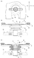
図1〜図5に示すように、本発明の接続部材1は、飲料が流れる流路が内部に形成された接続部材本体3と、接続部材本体3の上端に配設されて飲料容器5の密封蓋7を穿孔する先鋭端部9と、接続部材本体3の下端に連結されて飲料を二方向に分岐排出する排出管11とを備えている。ここで、図1(B)が正面図を示しており、後述する飲料ディスペンサDを正面から見た場合に(図2参照)、接続部材1が図1(B)に示すような向きで設置される。
[Connecting member]
As shown in FIGS. 1-5, the
接続部材本体3は、先鋭端部9を担持する挿入部3aと、内部の流路を分岐させる分岐部3cと、挿入部3aと分岐部3cとの間を連結する連結部3bとからなる。挿入部3aは、飲料容器5の飲料導出口5dに挿入できるような所定の直径で形成されている。また、連結部3bの外周面には弾性材料(例えば、ゴム)などから構成されるOリング3dが配置されている。このOリング3dは、飲料導出口5d内の管状部材5bを密封して飲料が外部に漏洩しないようにするためのものである。分岐部3cには、内部に分岐した流路が形成され、より詳しくは、先鋭端部9側から接続部材本体3の長手方向に向かって内部流路が形成されると共に、この内部流路に対して直交する方向に排出流路が形成されている。すなわち、T字状の流路が形成されることとなる。ただし、本発明は二方向に分岐する場合に限定されるものではなく、三方向あるいはそれ以上の流路に分岐するような構造にしてもよい。
The connection member
接続部材1の先鋭端部9は略円筒状に形成され、かつ端面(飲料容器5に対向する側)がガイド面となっている。具体的にこのガイド面は、先鋭端部9の端面に飲料導出口5dの周縁5eが接触した場合に、飲料導出部材5aを切欠部25内での移動可能方向に沿って移動させるためのものであり、実際には傾斜面となっている。本実施形態の先鋭端部9は、図1(B)に示すように、正面から見た場合に右肩上がりの傾斜面となっている。このため、右側面図である図1(C)で見ると、先鋭端部9の最長部(飲料導出部材5aに最も近接する部分)を中心として左右両側に向かって下るような傾斜面が形成されることとなる。また、先鋭端部9の最短部(左側面側)には所定のスリット9aが形成されている。このスリット9aは、飲料容器5の密封蓋7を穿孔した際に、密封蓋7の先鋭端部分が脱落しないように、一部に切り残しを形成するためのものである。
The sharp end 9 of the connecting
更に先鋭端部9には、右側面側に所定の貫通孔9bが形成されている。この貫通孔9bは先鋭端部9が飲料容器5内に挿入された場合に、飲料容器5内の飲料を導出させるためのものである。このため、先鋭端部9が飲料容器5内に侵入した場合に、貫通孔9bの全体が飲料容器5内に入り込むような位置に設けられている。尚、本実施形態では貫通孔9bは1つだけ形成されているが、本発明はこれに限定されるものではなく、2つ或いはそれ以上設けてもよい。また、貫通孔9bは単純な円形に限定されるものはなく、どのよう
な形状であってもよい。
Further, a predetermined through
接続部材本体3に接合された2本の排出管11は、分岐部3cの下端部に設けられて、相互に反対方向に向かって突出している。排出管11の表面には抜け防止部が形成され、排出管11に接続される配管系統2a,2bが抜けるのを防止するようになっている。
The two
以上説明した接続部材1はステンレス鋼から構成されている。具体的にはステンレス鋼の丸棒を削り出すことで接続部材本体3及び先鋭端部9が形成される。そして、接続部材本体3の内部に流路が形成される。その後、接続部材本体3の分岐部に排出管11が溶接によって接合される。ただし、本発明の接続部材1の材料はステンレス鋼に限定されるものではなく、飲料に対して安定で腐食などの特性変化を生じないものであれば、他の金属や非金属材料を用いてもよい。
The connecting
[操作部]
操作部29は、図6に示すように、接続部材1に係合されて飲料容器5の押込み方向Pに沿って配設されるレバー部材である。より詳しくは、操作部29は接続部材1を左右両側から支持すると共に軸30を中心として上下方向へ回動可能に設けられている。また、操作部29の手前端部には把持部29aが設けられ、使用者は当該把持部29aを操作するようになっている。このような構成により、飲料容器5の飲料導出部材5aと飲料ディスペンサDを接続する場合は、飲料容器5を容器載置台23上に載置して、飲料導出部材5aを切欠部25に差し込む。そして、指により操作部29の把持部29aを持って上方に移動させる。それにより接続部材1の尖鋭端部9が上方に移動して飲料導出口5d内に挿入される。一方、飲料容器5と飲料ディスペンサとの接続を解除する場合は、反対に、操作部29の把持部29aを持って下方に移動させる。
[Operation section]
As shown in FIG. 6, the
尚、上記実施形態は接続部材1を押し上げて飲料導出口5dに挿入する場合を説明したが、本発明はこれに限定されるものではない。すなわち、図11及び図12で示したような、容器載置台123を傾斜状態から水平状態に回動させることで、飲料導出口105cの中へ、固定されている接続部材101が挿入されるような構造にも適用可能である。具体的には、容器載置台123を回動させて押し下げることにより、飲料導出口105cの周縁105dと先鋭端部109が接触する。先鋭端部109が上記実施形態で説明したようなガイド面となっていることで、飲料導出部材105aを適切に移動させることになる。
The above embodiment has been described with respect to the case to be inserted into the
[飲料ディスペンサ]
次に、上記接続機構Sが用いられる飲料ディスペンサDについて説明する。図2に構成概要を示すように、飲料ディスペンサDは上部に冷却室21を備えており、この冷却室21に飲料容器5を収容できるようになっている。より具体的には、冷却室21の下方に上記した容器載置台23が水平方向に設けられ、この容器載置台23上に飲料容器5が載置されるようになっている。容器載置台23には正面からみて中央部に所定の切欠部25が形成されており(図3参照)、この切欠部25に、飲料容器5の飲料導出部材5aの外周面に形成されたくびれ部5cが押し込まれるようになっている。飲料導出部材5aのくびれ部5cが切欠部25に押込まれると、飲料容器5の押込み方向Pに対して直交する左右方向Q及び上下方向の移動は規制される。尚、冷却室21は本発明にとって必須は構成ではなく、常温の容器収納室であってもよい。また、接続機構Sの周辺、特に接続部材1と飲料導出部材5aの衛生状態が適切に保たれる限りにおいては、飲料に雑菌が混入することはないため、飲料容器5自体は外気に直接さらされるような状態に置かれてもよい。
[Beverage dispenser]
Next, the beverage dispenser D in which the connection mechanism S is used will be described. As shown in FIG. 2, the beverage dispenser D is provided with a cooling
この飲料ディスペンサDにおいて、飲料容器5はバッグインボックス型容器の密封容器であり、飲料容器5の内袋に連結されて設けられている飲料導出部材5aを、接続部材1
を介して飲料ディスペンサD側の各配管系統2a,2b(図2及び図3参照)と接続する。ここで、バッグインボックス型容器とは、段ボール紙などから形成された外箱Bと、この外箱Bの中に配置される可撓性バッグからなる容器である。飲料導出部材5aは可撓性のバッグに取付けられているため、外箱B自体は動かない状態でも、外力が加わると飲料導出部材5aは多少移動することができるようになっている。また、飲料導出口5dの奥部には上記した密封蓋7が設けられており、無菌状態で充填されている飲料の無菌化を保全している。
In this beverage dispenser D, the
And connected to each
飲料ディスペンサD中の飲料容器5は冷却室21によって約4〜10℃に冷却することができる。これは、飲料を飲用に好ましい低温にするためと、飲料容器5中の飲料の汚染の可能性を低減させるために雑菌の繁殖しにくい低温で飲料を保存するためである。また、飲料容器5と飲料ディスペンサDの接続部位である接続部材1も冷却室21内で外気とは遮断された状態で、かつ低温雰囲気下におかれるため、雑菌が侵入、繁殖しにくい。
The
飲料容器5の飲料導出口5dには、上記した接続部材1が挿入されている。より詳しくは、図3に示すように、飲料導出部材5aの内部には接続部材1のOリング3dに対応した内径の管状部材5bが設けられている。このため、接続部材1の先鋭端部9が飲料容器5の密封蓋7を穿孔した場合でも、Oリング3dが管状部材5bとの協働作用によって、飲料の漏洩を防止することができる。また、飲料容器5を交換する場合には、操作部29を押し下げて接続部材1を飲料導出口5dから抜き、飲料容器5を正面から手前に引き出すことで、空の飲料容器5を取り出すことかできる。そして、新しい飲料容器5を正面から奥に向けて(押込み方向P)水平に押し込むことで、上記したように飲料導出部材5aが切欠部25に押込まれる。その後、操作部29を押し上げることによって接続部材1を飲料導出口5dに挿入し、密封蓋7を穿孔して飲料を導出することができるようになる(図3参照)。
The
また、図2に示すように、飲料ディスペンサDの中段には、飲料を注ぐための注ぎ口27が設けられている。本実施形態の飲料ディスペンサDでは、2つの注ぎ口27が設けられている。この注ぎ口27には、上記した接続部材1を介して配管系統2a.2bが接続され、飲料容器5内の飲料が供給される。尚、本実施形態の注ぎ口27は、それぞれ冷水及び熱水を提供できるようになっているため、飲料ディスペンサDの内部には、飲料を一旦貯留する加熱タンク4aと冷却タンク4bが設けられている。加熱タンク4aへは配管系統2aから飲料が供給され、冷却タンク4bへは配管系統2bから飲料が供給されるようになっている。また、加熱タンク4aの表面には飲料を加熱するための加熱機器6aが設けられ、一方、冷却タンク4bの表面には飲料を冷却するための冷却機器6bが設けられている。
Moreover, as shown in FIG. 2, the
[作用]
次に、図4に基づいて、本実施形態に係る接続機構Sの作用について説明する。ここで、図4(A)は接続部材1と飲料導出部材5aとを上方から見た平面図であり、図4(B)はその側面図である。但し、説明の便宜を図るため、図4(A)では飲料導出部材5aを一点鎖線で示し、図4(B)は飲料導出部材5aのみを断面図としている。また、この図においては左方が正面側であり、飲料容器5が飲料ディスペンサDに押込まれる際には、飲料導出部材5aは左方から右方へ移動することとなる(押込み方向P)。
[Action]
Next, based on FIG. 4, the effect | action of the connection mechanism S which concerns on this embodiment is demonstrated. 4A is a plan view of the connecting
図4において、飲料導出部材5aは接続部材1に対して左方にずれている。これは、換言すると飲料容器5の飲料ディスペンサDに対する押込み量が不足している状態である。そして、この状態における飲料導出部材5aの移動可能方向は、切欠部25に沿った方向P或いはその逆の方向である。本来は、飲料導出口5dの中心と先鋭端部9の中心とがほぼ一致していなければならないが、この図では押込み量が不足しているために、飲料導出口5dの周縁が先鋭端部9の先端に接触してしまっている。このような状態は、冷却室21の容器載置台23に形成された切欠部25に飲料導出部材5aを挿入する際に、飲料導出部材5aが切欠部25にひっかかって停止してしまい、使用者が最奥部まで飲料容器5を押込んだと勘違いをした場合に生じる。
In FIG. 4, the
このような状態において、接続部材1を飲料導出口5dに挿入するために、使用者は操作部29を使って接続部材1を上方に持ち上げようとする。このとき、図4(B)に示すように、先鋭端部9が飲料導出口5dの周縁5eに接触するが、先鋭端部9への接触部は所定の傾斜αを有する右肩下がりのガイド面(傾斜面)になっているため、飲料導出部材5aに対して右方(飲料容器5の押込み方向P)への分力が発生し、飲料導出部材5aを適切に移動させることとなる。即ち、飲料導出部材5aと接続部材1との相対位置関係が適切となるように、飲料導出部材5aの位置が修正されるのである。このため、飲料容器5の押込み方向Pに向かって傾斜面を有しない従来の接続部材と比較して、飲料導出口5dの内面壁にキズをつけることがなくなる。
In such a state, in order to insert the
尚、上記説明は飲料導出口5dの周縁が先鋭端部9の最長部(最も飲料容器に近接した部分)よりも右方に位置する場合である。しかしながら、実際の使用態様においては、図5に示すように、飲料導出口5dの周縁5eが先鋭端部9の最長部よりも左方に位置する場合もある。このような状態では先鋭端部9の先端が飲料導出部材5aの下面に当接し、それ以上は接続部材1を上方に押し上げることができない。このため、使用者は飲料容器5の位置が不適切であると気付くか、あるいは何らかの不具合であると気付く。従って、飲料導出口5d内の管状部材5bの内面壁にキズを付けることはない。
In addition, the said description is a case where the periphery of 5d of drink outlets is located in the right side rather than the longest part (part closest to the beverage container) of the sharp end 9. However, in an actual usage mode, as shown in FIG. 5, the
以上説明したように、本発明は接続部材1における先鋭端部9の先端が飲料容器5の押込み方向P(切欠部25内での移動可能方向)に沿って僅かでも傾斜したガイド面であればよい。このガイド面によって、接続部材1の上昇に伴って飲料導出部材5aが適切な位置に導かれるか、或いは接続部材1自体を押し上げることができなくなるので、飲料導出口5dの内面壁にキズを付けてしまうという中間的な作用を排除することができることとなる。
As described above, the present invention is a guide surface in which the tip of the sharp end 9 in the connecting
[第2の実施形態]
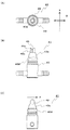
次に、図7に基づいて、本発明の第2の実施形態で用いられる接続部材31について説明する。当該実施形態に係る接続部材31は、先鋭端部39の構造を除いて第1の実施形態と同一である。このため、先鋭端部39のみ説明し、それ以外の部分については説明を省略する。本実施形態の先鋭端部39は、最長部が左側面側にきて、最短部が右側面側にくる点で第1の実施形態と異なっている。このため、最長部側にスリット39aが形成され、最短部側に貫通孔39bが形成されている。このため、接続部材31の右側面図を示す図7(C)においては、貫通孔39bが形成された最短部側が見えている。このような構成の接続部材31であっても、図7(C)に示すように、飲料容器の押込み方向Pに沿って先鋭端部39の先端が傾斜面を有することから、第1の実施形態と同様に作用する。
[Second Embodiment]
Next, the
[第1の参考例]
次に、図8に基づいて本発明の第1の参考例で使用される接続部材41について説明する。当該参考例に係る接続部材41は、先鋭端部49及び挿入部43aの構造を除いて第1の実施形態と同一である。このため、先鋭端部49及び挿入部43aのみ説明し、それ以外の部分については説明を省略する。本参考例の先鋭端部49は、最長部が左側面側及び右側面側の両側に形成され、最短部が正面側及び背面側にくる点で第1の実施形態と異なっている。すなわち、先鋭端部は、飲料容器5の押込み方向Pに対して直交する左右両方向側が最も近接しているこのため、正面から見た場合(図8(B)参照)、先鋭端部49の先端はV字状の傾斜面となっている。また、スリット49aは正面側に形成されると共に、貫通孔49bは左側面側に形成されている。そして、接続部材41の右側面図である図8(C)に示すように、飲料容器の押込み方向Pに沿って先鋭端部49の先端が傾斜面を有することから、第1の実施形態と同様に作用する。
[ First Reference Example ]
Next, the
加えて、本参考例の接続部材41は、挿入部43aがテーパを有する円錐台形状となっている。このように挿入部43aを円錐台形状にすることにより、接続部材41の位置に対して飲料容器の飲料導出部材の位置がずれていても、飲料導出口の周縁が円錐台のテーパ面に当接する。この結果、接続部材41の上昇に伴って飲料導出部材が適切な位置に導かれることとなる。そして、最終的には接続部材41に装着されたOリング43dが飲料導出口の管状部材内に入り込み、接続部材と飲料導出部材の位置決めが適切に行われる。
In addition, the
[第2の参考例]
次に、図9に基づいて本発明の第2の参考例で使用される接続部材51について説明する。当該参考例に係る接続部材51は、先鋭端部59の構造を除いて第1の実施形態と略同一である。また、先鋭端部59は、上記した第1の参考例に係る先鋭端部49と同一である。すなわち、当該参考例の接続部材51の先鋭端部59は正面から見た場合にV字状に形成され、接続部材本体53の挿入部53aは円筒状となっている。このため、先鋭端部59の先端が飲料導入口の周縁に接触した場合には、第1の参考例と同様に作用することとなる。
[ Second Reference Example ]
Next, the
[第3の参考例]
次に、図10に基づいて本発明の第3の参考例で使用される接続部材61について説明する。当該参考例に係る接続部材61は、挿入部63aの構造を除いて第1の参考例と略同一である。当該参考例に係る接続部材61において、挿入部63aは飲料導出部材側の端部に面取部からなるガイド部63eが形成され、これに続いて所定の傾斜の円錐台形状が形成され、下端部は円筒部となっている。このような構成により、先鋭端部69が飲料導入口の周縁に接触した場合には第1の参考例と同様に作用し、その後はガイド部63e及び円錐台形状部の作用により、飲料導出部材を適切な位置に導くことができる。
[ Third Reference Example ]
Next, the
本発明は、飲料容器の飲料導出口を飲料ディスペンサに接続するための接続機構及びこれを用いた飲料ディスペンサに利用することができる。 The present invention can be used for a connection mechanism for connecting a beverage outlet of a beverage container to a beverage dispenser and a beverage dispenser using the connection mechanism.
S 接続機構
1 接続部材
3 接続部材本体
3a 挿入部
5 飲料容器
5a 飲料導出部材
5b 管状部材
5c くびれ部
5d 飲料導出口
5e 飲料導出口の周縁
7 密封蓋
9 先鋭端部
9a スリット
9b 貫通孔
11 排出管
21 冷却室
23 容器載置台
25 切欠部
27 注ぎ口
B 外箱
D 飲料ディスペンサ
P 飲料容器押込み方向
DESCRIPTION OF SYMBOLS S
Claims (5)
前記切欠部は、前記飲料容器を飲料ディスペンサに設置する場合の前記飲料導出部材の移動可能方向に沿って形成されており、
前記飲料容器は、外箱とこの外箱内に収容される可撓性のバッグとから構成され、
前記先鋭端部の前記飲料導出口に対向する端面は、この端面に前記飲料導出口の周縁が接触した場合に前記飲料導出部材を前記切欠部内での移動可能方向へ移動させるガイド面となっており、前記ガイド面は飲料導出部材の前記移動可能方向に対して直交する方向に傾斜した単一の平面からなる端面によって形成されて、前記飲料導出部材に対して前記移動可能方向に沿った傾斜面となっていることを特徴とする接続機構。 The piping system and having a container table with a beverage delivering member can engage the notch portion provided in the beverage container, a circular cylindrical sharp tip portion to be inserted into the beverage delivering port of the beverage delivering member to the distal end In a connection mechanism between a beverage container and a beverage dispenser, comprising a connection member to be connected and an operation unit for inserting the connection member into the beverage outlet.
The notch is formed along the movable direction of the beverage outlet member when the beverage container is installed in a beverage dispenser,
The beverage container is composed of an outer box and a flexible bag accommodated in the outer box,
The end surface of the sharp end facing the beverage outlet is a guide surface that moves the beverage outlet member in a movable direction within the notch when the peripheral edge of the beverage outlet contacts the end surface. The guide surface is formed by an end surface made of a single plane inclined in a direction orthogonal to the movable direction of the beverage outlet member, and is inclined along the movable direction with respect to the beverage outlet member A connection mechanism characterized by a surface .
Priority Applications (11)
| Application Number | Priority Date | Filing Date | Title |
|---|---|---|---|
| JP2007033467A JP4575397B2 (en) | 2007-02-14 | 2007-02-14 | Connection mechanism between beverage container and beverage dispenser and beverage dispenser using the same |
| TW097104343A TW200848353A (en) | 2007-02-14 | 2008-02-04 | A connection mechanism between a beverage container and a beverage dispenser and a beverage dispenser using the same |
| AU2008215492A AU2008215492B2 (en) | 2007-02-14 | 2008-02-05 | A connection mechanism between a beverage container and a beverage dispenser and a beverage dispenser using the same |
| EP08704539A EP2125602A2 (en) | 2007-02-14 | 2008-02-05 | A connection mechanism between a beverage container and a beverage dispenser and a beverage dispenser using the same |
| MYPI20093345A MY162529A (en) | 2007-02-14 | 2008-02-05 | A connection mechanism between a beverage container and a beverage dispenser and a beverage dispenser using the same |
| CA2677477A CA2677477C (en) | 2007-02-14 | 2008-02-05 | A connection mechanism between a beverage container and a beverage dispenser and a beverage dispenser using the same |
| US12/527,056 US8196777B2 (en) | 2007-02-14 | 2008-02-05 | Connection mechanism between a beverage container and a beverage dispenser and a beverage dispenser using the same |
| RU2009134186/12A RU2401797C1 (en) | 2007-02-14 | 2008-02-05 | Jointing mechanism between container for drinks and drink distributing device with said mechanism, and drink distributing device with said mechanism |
| PCT/JP2008/052220 WO2008099796A2 (en) | 2007-02-14 | 2008-02-05 | A connection mechanism between a beverage container and a beverage dispenser and a beverage dispenser using the same |
| CN200810074235XA CN101244798B (en) | 2007-02-14 | 2008-02-13 | A connection mechanism between a beverage container and a beverage dispenser and a beverage dispenser |
| HK09101672.4A HK1121730B (en) | 2007-02-14 | 2009-02-20 | A connection mechanism between a beverage container and a beverage dispenser and a beverage dispenser using the same |
Applications Claiming Priority (1)
| Application Number | Priority Date | Filing Date | Title |
|---|---|---|---|
| JP2007033467A JP4575397B2 (en) | 2007-02-14 | 2007-02-14 | Connection mechanism between beverage container and beverage dispenser and beverage dispenser using the same |
Publications (2)
| Publication Number | Publication Date |
|---|---|
| JP2008195430A JP2008195430A (en) | 2008-08-28 |
| JP4575397B2 true JP4575397B2 (en) | 2010-11-04 |
Family
ID=39673176
Family Applications (1)
| Application Number | Title | Priority Date | Filing Date |
|---|---|---|---|
| JP2007033467A Expired - Fee Related JP4575397B2 (en) | 2007-02-14 | 2007-02-14 | Connection mechanism between beverage container and beverage dispenser and beverage dispenser using the same |
Country Status (10)
| Country | Link |
|---|---|
| US (1) | US8196777B2 (en) |
| EP (1) | EP2125602A2 (en) |
| JP (1) | JP4575397B2 (en) |
| CN (1) | CN101244798B (en) |
| AU (1) | AU2008215492B2 (en) |
| CA (1) | CA2677477C (en) |
| MY (1) | MY162529A (en) |
| RU (1) | RU2401797C1 (en) |
| TW (1) | TW200848353A (en) |
| WO (1) | WO2008099796A2 (en) |
Families Citing this family (5)
| Publication number | Priority date | Publication date | Assignee | Title |
|---|---|---|---|---|
| JP4566149B2 (en) * | 2006-03-27 | 2010-10-20 | スリーエム イノベイティブ プロパティズ カンパニー | Method for producing independent glass film |
| WO2012077727A1 (en) * | 2010-12-08 | 2012-06-14 | 旭硝子株式会社 | Adhesive-layer-equipped transparent surface material, display device, and methods for producing same |
| IL211021A (en) | 2011-02-02 | 2014-05-28 | Neviot Nature Galilee Ltd | Water dispenser with bag in a box unit |
| JP6045368B2 (en) * | 2013-01-24 | 2016-12-14 | サーパス工業株式会社 | Fluid equipment unit |
| CN204813445U (en) * | 2015-07-06 | 2015-12-02 | 深圳安吉尔饮水产业集团有限公司 | Water -stop guiding device in bags and water water dispenser in bags thereof |
Family Cites Families (19)
| Publication number | Priority date | Publication date | Assignee | Title |
|---|---|---|---|---|
| US3118288A (en) * | 1964-01-21 | Refrigerax s system | ||
| DE2736272C3 (en) * | 1977-08-11 | 1982-03-04 | Bier-Drive AG, Chur, Chur | Method for filling a foil bag in a pressure tank with a carbonated drink, in particular beer |
| AU519675B2 (en) * | 1978-05-30 | 1981-12-17 | Wrightcel Limited | Container |
| US4375864A (en) * | 1980-07-21 | 1983-03-08 | Scholle Corporation | Container for holding and dispensing fluid |
| US4469249A (en) | 1980-12-04 | 1984-09-04 | Diemoulders Proprietary Limited | Apparatus for dispensing liquids |
| DE3429559A1 (en) * | 1984-08-10 | 1986-02-20 | Gebrüder Mogler GmbH & Co., 7100 Heilbronn | DEVICE FOR PICKING CONTAINERS FILLED WITH LIQUID |
| FR2619612A1 (en) * | 1987-08-19 | 1989-02-24 | Dufrene Alain | Tap for drawing off liquids |
| US5732853A (en) * | 1992-11-03 | 1998-03-31 | Bentfield Europe B.V. | Dosing unit comprising a dispensing device and a container bag unit |
| JP3520946B2 (en) * | 1996-03-05 | 2004-04-19 | 株式会社ダイオーズサービシーズ | Drinking water dispenser |
| US6095433A (en) * | 1997-08-28 | 2000-08-01 | Langdon (London) Limited | Irrigation system and method of performing same |
| JP3746605B2 (en) * | 1997-12-26 | 2006-02-15 | 富士電機リテイルシステムズ株式会社 | Drinking water dispenser |
| AUPP243598A0 (en) * | 1998-03-18 | 1998-04-09 | Rapak Asia Pacific Limited | Improvements relating to tote bins |
| US6223940B1 (en) * | 1998-11-09 | 2001-05-01 | Radius International Limited Partnership | Fluid storage container and dispenser, and method of dispensing |
| US6398073B1 (en) * | 2000-07-24 | 2002-06-04 | Bag O Water Limited | Fluid dispensing system with collapsible container |
| US6726061B2 (en) * | 2001-03-01 | 2004-04-27 | Afp Advanced Food Products Llc | System for dispensing a viscous comestible product |
| AU2003241754B2 (en) * | 2002-05-23 | 2008-12-18 | Eiji Yoshida | Device, unit, and system for fluid extraction |
| UA81478C2 (en) * | 2003-05-06 | 2008-01-10 | Method for dispensing a beverage, dispensing assembly and container unit | |
| US7188749B2 (en) | 2003-10-23 | 2007-03-13 | Ammm Patent Holdings, Llc | Container adapted to hold and dispense bagged fluids |
| JP4349985B2 (en) | 2004-07-15 | 2009-10-21 | フジテクノ株式会社 | Beverage server and connection for beverage server |
-
2007
- 2007-02-14 JP JP2007033467A patent/JP4575397B2/en not_active Expired - Fee Related
-
2008
- 2008-02-04 TW TW097104343A patent/TW200848353A/en not_active IP Right Cessation
- 2008-02-05 AU AU2008215492A patent/AU2008215492B2/en not_active Ceased
- 2008-02-05 WO PCT/JP2008/052220 patent/WO2008099796A2/en not_active Ceased
- 2008-02-05 MY MYPI20093345A patent/MY162529A/en unknown
- 2008-02-05 RU RU2009134186/12A patent/RU2401797C1/en not_active IP Right Cessation
- 2008-02-05 US US12/527,056 patent/US8196777B2/en not_active Expired - Fee Related
- 2008-02-05 EP EP08704539A patent/EP2125602A2/en not_active Withdrawn
- 2008-02-05 CA CA2677477A patent/CA2677477C/en not_active Expired - Fee Related
- 2008-02-13 CN CN200810074235XA patent/CN101244798B/en not_active Expired - Fee Related
Also Published As
| Publication number | Publication date |
|---|---|
| CN101244798A (en) | 2008-08-20 |
| MY162529A (en) | 2017-06-15 |
| AU2008215492B2 (en) | 2010-09-09 |
| CA2677477C (en) | 2013-11-12 |
| US20100018993A1 (en) | 2010-01-28 |
| CA2677477A1 (en) | 2008-08-21 |
| WO2008099796A2 (en) | 2008-08-21 |
| CN101244798B (en) | 2012-06-20 |
| EP2125602A2 (en) | 2009-12-02 |
| RU2401797C1 (en) | 2010-10-20 |
| HK1121730A1 (en) | 2009-04-30 |
| AU2008215492A1 (en) | 2008-08-21 |
| US8196777B2 (en) | 2012-06-12 |
| JP2008195430A (en) | 2008-08-28 |
| TWI337980B (en) | 2011-03-01 |
| TW200848353A (en) | 2008-12-16 |
| WO2008099796A3 (en) | 2008-10-30 |
Similar Documents
| Publication | Publication Date | Title |
|---|---|---|
| JP4575397B2 (en) | Connection mechanism between beverage container and beverage dispenser and beverage dispenser using the same | |
| US10683112B2 (en) | Apparatus for closing a fluid container | |
| KR20030015270A (en) | Drink dispensing device and container for drink provided with positioning means | |
| SK16962002A3 (en) | Drink dispenser assembly and container for drink and drink dispensing line | |
| JP2017538632A (en) | Pressurized liquid dispenser with a three-way valve for venting containers | |
| US7628299B2 (en) | Threaded spout | |
| BR112013002967B1 (en) | system for dispensing an additive in a liquid stream, refrigerator door, and method for dispensing an additive in a liquid stream | |
| JPH0718614Y2 (en) | Fluid connector | |
| JP6600225B2 (en) | Beverage dispenser | |
| EP2231505B1 (en) | An adapter set for use in combination with a collapsible beverage container | |
| JP2013165805A (en) | Container opening mechanism and endoscope washing device | |
| KR101196276B1 (en) | A connection mechanism between a beverage container and a beverage dispenser and a beverage dispenser using the same | |
| KR20090096967A (en) | Beer Supply Assembly and Beer Supply | |
| HK1121730B (en) | A connection mechanism between a beverage container and a beverage dispenser and a beverage dispenser using the same | |
| JP2013165803A (en) | Liquid supply mechanism and endoscope washing device | |
| WO2012042503A1 (en) | Gas distributing bar for beverage dispensing devices from containers such as bottles and the like | |
| JP2017081618A (en) | Beverage moving and filling tool | |
| JP4333972B2 (en) | Bag-in-box filling port | |
| GB2257116A (en) | Dispensing cooled drink from bag-in-box. | |
| JP3639032B2 (en) | Cooled beverage supply device | |
| JP2025007165A (en) | Beverage Server | |
| KR200431483Y1 (en) | Sorting apparatus for beverage containers | |
| JP2017105524A (en) | Dispenser | |
| JP2007236685A (en) | Water feeder | |
| JP2008195406A (en) | Beverage dispenser |
Legal Events
| Date | Code | Title | Description |
|---|---|---|---|
| A711 | Notification of change in applicant |
Free format text: JAPANESE INTERMEDIATE CODE: A712 Effective date: 20090422 |
|
| A621 | Written request for application examination |
Free format text: JAPANESE INTERMEDIATE CODE: A621 Effective date: 20090917 |
|
| A871 | Explanation of circumstances concerning accelerated examination |
Free format text: JAPANESE INTERMEDIATE CODE: A871 Effective date: 20090917 |
|
| A975 | Report on accelerated examination |
Free format text: JAPANESE INTERMEDIATE CODE: A971005 Effective date: 20091020 |
|
| A131 | Notification of reasons for refusal |
Free format text: JAPANESE INTERMEDIATE CODE: A131 Effective date: 20091022 |
|
| A521 | Request for written amendment filed |
Free format text: JAPANESE INTERMEDIATE CODE: A523 Effective date: 20091218 |
|
| A02 | Decision of refusal |
Free format text: JAPANESE INTERMEDIATE CODE: A02 Effective date: 20100127 |
|
| A521 | Request for written amendment filed |
Free format text: JAPANESE INTERMEDIATE CODE: A523 Effective date: 20100423 |
|
| A911 | Transfer to examiner for re-examination before appeal (zenchi) |
Free format text: JAPANESE INTERMEDIATE CODE: A911 Effective date: 20100428 |
|
| A131 | Notification of reasons for refusal |
Free format text: JAPANESE INTERMEDIATE CODE: A131 Effective date: 20100621 |
|
| A521 | Request for written amendment filed |
Free format text: JAPANESE INTERMEDIATE CODE: A523 Effective date: 20100701 |
|
| TRDD | Decision of grant or rejection written | ||
| A01 | Written decision to grant a patent or to grant a registration (utility model) |
Free format text: JAPANESE INTERMEDIATE CODE: A01 Effective date: 20100721 |
|
| A01 | Written decision to grant a patent or to grant a registration (utility model) |
Free format text: JAPANESE INTERMEDIATE CODE: A01 |
|
| A61 | First payment of annual fees (during grant procedure) |
Free format text: JAPANESE INTERMEDIATE CODE: A61 Effective date: 20100819 |
|
| R150 | Certificate of patent or registration of utility model |
Free format text: JAPANESE INTERMEDIATE CODE: R150 Ref document number: 4575397 Country of ref document: JP Free format text: JAPANESE INTERMEDIATE CODE: R150 |
|
| FPAY | Renewal fee payment (event date is renewal date of database) |
Free format text: PAYMENT UNTIL: 20130827 Year of fee payment: 3 |
|
| FPAY | Renewal fee payment (event date is renewal date of database) |
Free format text: PAYMENT UNTIL: 20130827 Year of fee payment: 3 |
|
| S111 | Request for change of ownership or part of ownership |
Free format text: JAPANESE INTERMEDIATE CODE: R313113 |
|
| FPAY | Renewal fee payment (event date is renewal date of database) |
Free format text: PAYMENT UNTIL: 20130827 Year of fee payment: 3 |
|
| R350 | Written notification of registration of transfer |
Free format text: JAPANESE INTERMEDIATE CODE: R350 |
|
| R250 | Receipt of annual fees |
Free format text: JAPANESE INTERMEDIATE CODE: R250 |
|
| S531 | Written request for registration of change of domicile |
Free format text: JAPANESE INTERMEDIATE CODE: R313531 |
|
| R350 | Written notification of registration of transfer |
Free format text: JAPANESE INTERMEDIATE CODE: R350 |
|
| R250 | Receipt of annual fees |
Free format text: JAPANESE INTERMEDIATE CODE: R250 |
|
| S111 | Request for change of ownership or part of ownership |
Free format text: JAPANESE INTERMEDIATE CODE: R313114 |
|
| R350 | Written notification of registration of transfer |
Free format text: JAPANESE INTERMEDIATE CODE: R350 |
|
| R250 | Receipt of annual fees |
Free format text: JAPANESE INTERMEDIATE CODE: R250 |
|
| R250 | Receipt of annual fees |
Free format text: JAPANESE INTERMEDIATE CODE: R250 |
|
| R250 | Receipt of annual fees |
Free format text: JAPANESE INTERMEDIATE CODE: R250 |
|
| S111 | Request for change of ownership or part of ownership |
Free format text: JAPANESE INTERMEDIATE CODE: R313117 |
|
| R350 | Written notification of registration of transfer |
Free format text: JAPANESE INTERMEDIATE CODE: R350 |
|
| R250 | Receipt of annual fees |
Free format text: JAPANESE INTERMEDIATE CODE: R250 |
|
| R250 | Receipt of annual fees |
Free format text: JAPANESE INTERMEDIATE CODE: R250 |
|
| R250 | Receipt of annual fees |
Free format text: JAPANESE INTERMEDIATE CODE: R250 |
|
| R250 | Receipt of annual fees |
Free format text: JAPANESE INTERMEDIATE CODE: R250 |
|
| R250 | Receipt of annual fees |
Free format text: JAPANESE INTERMEDIATE CODE: R250 |
|
| R250 | Receipt of annual fees |
Free format text: JAPANESE INTERMEDIATE CODE: R250 |
|
| LAPS | Cancellation because of no payment of annual fees |