JP2009242602A - Self-adhesive sheet - Google Patents
Self-adhesive sheet Download PDFInfo
- Publication number
- JP2009242602A JP2009242602A JP2008091091A JP2008091091A JP2009242602A JP 2009242602 A JP2009242602 A JP 2009242602A JP 2008091091 A JP2008091091 A JP 2008091091A JP 2008091091 A JP2008091091 A JP 2008091091A JP 2009242602 A JP2009242602 A JP 2009242602A
- Authority
- JP
- Japan
- Prior art keywords
- adhesive sheet
- central
- pressure
- sensitive adhesive
- gap
- Prior art date
- Legal status (The legal status is an assumption and is not a legal conclusion. Google has not performed a legal analysis and makes no representation as to the accuracy of the status listed.)
- Pending
Links
Images


Abstract
Description
基材の一方の主面に粘着層を備えた粘着シートは、例えば破れた紙の修復等に広く利用されている。また、粘着シートの基材として、彩色を施した透明フィルムや金属を蒸着等した金属箔を備えることによって、例えば化粧版として電子機器等の筐体表面に適用されている。 An adhesive sheet having an adhesive layer on one main surface of a substrate is widely used for repairing, for example, torn paper. Moreover, as a base material of an adhesive sheet, it is applied to the surface of housing | casing, such as an electronic device, for example as a decorative plate by providing the metal foil which vapor-deposited the transparent film and metal which gave a color.
基材の一方の主面に粘着材を均一塗工した粘着シートを筐体表面に貼付すると、粘着シートの基材と筐体表面との間に空気が入り込み、入り込んだ空気はふくれとして粘着シート表面に現れ、化粧版としての美観を著しく損なう。 When a pressure-sensitive adhesive sheet with a uniform adhesive material applied to one main surface of the base material is attached to the surface of the housing, air enters between the base material of the pressure-sensitive adhesive sheet and the surface of the housing, and the air that has entered the pressure-sensitive adhesive sheet functions as a blister Appears on the surface and remarkably detracts from the beauty of the cosmetic plate.
この課題の解決策として、特許文献1では、表面シート上に均一塗工した粘着材で構成した基本平坦面の上に散点状に独立した小凸部の粘着材を形成した粘着シートが提案されている。この粘着シートを被粘着物に貼付すると、小凸部の先端部が優先的に貼り付くため、表面シートと被粘着物との間に外部に連通する空間を形成することができるため、入り込んだ空気がふくれとなることを抑制できるとしている。
しかしながら、特許文献1の構成の粘着シートを用いると、被粘着物に貼付する際に表面シートから押圧する力を極めて微妙に制御する必要があり、押圧力を少し強めただけで基本平坦面を形成する粘着材に被粘着物が貼り付く、及び/または表面シートを押圧する押圧手段からの熱等で小凸部が基本平坦面に埋没する等の原因で、小凸部本来の機能が発揮し得ず、貼付の際に結局空気が入り込み、空気ふくれを抑制することはできなかった。
However, when the pressure-sensitive adhesive sheet having the structure of
これは基本平坦面が小凸部と同じ材料の粘着材で構成されていることが主原因と考え、基材の一方の主面に小凸部に相当する突起状または列状の粘着材を印刷により粘設し、基材と被粘着物との間に空気道を備える改良した粘着シートを適用してみた。当該改良した粘着シートにより、粘着材と粘着材との間隙は粘着材を備えないため、空気道を確実に確保することができ、仮に貼付工程で基材と被粘着物との間に空気が入り込んだとしても、当該空気は空気道から押し出すことができ、空気ふくれは完全に解消することができた。 This is mainly due to the fact that the basic flat surface is made of the same material as that of the small protrusions, and the protrusions or rows of adhesives corresponding to the small protrusions are formed on one main surface of the substrate. I tried to apply an improved pressure-sensitive adhesive sheet that was stuck by printing and provided with an air passage between the substrate and the object to be adhered. With the improved pressure-sensitive adhesive sheet, the gap between the pressure-sensitive adhesive material and the pressure-sensitive adhesive material does not include the pressure-sensitive adhesive material, so that an air passage can be ensured reliably. Even if it entered, the air could be pushed out of the air passage, and the air blister could be completely eliminated.
しかしながら、上記改良した粘着シートを長期間使用すると、酸化性ガスまたは塩基性ガス等の反応性ガス成分や、汗、表面の汚れを落とす界面活性剤または飲み物等の液体成分などの異物が、ふくれを解消する空気道から粘着シートと被粘着物との間に入り込み、粘着材及び/または基材に施した色彩層や金属層の装飾物質等を劣化させ、粘着シートの剥離や当該異物が突起状または列状の粘着材周辺部に付着堆積し、それら付着堆積した汚れが基材を介して視認でき、粘着シート自体が持つ美観を損ない、例えば化粧板としての機能を損なう場合があった。 However, when the above-mentioned improved adhesive sheet is used for a long period of time, foreign substances such as reactive gas components such as oxidizing gas or basic gas, and liquid components such as surfactants or drinks that remove dirt on the surface of the sweat will swell. Enters the space between the pressure-sensitive adhesive sheet and the object to be adhered through the air passage, which degrades the decorative material of the color layer and metal layer applied to the pressure-sensitive adhesive and / or the base material, and the pressure-sensitive adhesive sheet is peeled off and the foreign matter is projected. In some cases, the adhering and accumulating dirt is visible on the periphery of the adhesive material in the form of a line or in a row, and the adhered and deposited dirt can be visually recognized through the base material, which impairs the aesthetic appearance of the adhesive sheet itself, for example, impairs the function as a decorative board.
そこで、本発明は係る従来の課題に鑑み、貼付時に入り込んだ空気がふくれを形成することがないと共に、経時変化も抑制できる粘着シートを提供することを目的とする。 Then, in view of the conventional subject which concerns on this invention, while the air which entered at the time of sticking does not form a blister, it aims at providing the adhesive sheet which can also suppress a time-dependent change.
上記課題を解決する本発明の粘着シートは、基材の一方の主面に粘着層を備えた粘着シートであって、前記基材上で間隙部を介して選択的に粘設した中央領域と、前記中央領域を取り囲む周辺領域とを備え、前記中央領域の前記間隙部は前記周辺領域に連通し、前記周辺領域における間隙部の密度を前記中央領域における前記間隙部の密度未満の構成を有する。 The pressure-sensitive adhesive sheet of the present invention that solves the above problems is a pressure-sensitive adhesive sheet having a pressure-sensitive adhesive layer on one main surface of a base material, and a central region that is selectively adhered via a gap on the base material. A peripheral region surrounding the central region, wherein the gap portion of the central region communicates with the peripheral region, and the density of the gap portion in the peripheral region is less than the density of the gap portion in the central region. .
周辺領域における間隙部の密度を、中央領域における間隙部の密度未満とすることによって、粘着シートの貼付工程で空気が入り込んだとしても、中央領域から周辺領域に入り込んだ空気が移動し、周辺領域に移動した空気は貼付領域の外に押し出されるため、たまりを抑制できると共に、貼付領域の外からの反応性ガスや液体成分が貼付領域内部に進入することを抑制できる。 By setting the density of the gap in the peripheral area to be less than the density of the gap in the central area, even if air enters in the adhesive sheet sticking process, the air that has entered the peripheral area moves from the central area, and the peripheral area Since the air that has moved to the outside is pushed out of the sticking area, it is possible to suppress accumulation, and it is possible to prevent the reactive gas and liquid components from outside the sticking area from entering the sticking area.
次に、図面を参照して本発明の最良の実施形態について説明する。なお、以下の実施形態では電子機器等の外装を担う筐体表面に貼付する化粧粘着シートを例に挙げる。 Next, the best embodiment of the present invention will be described with reference to the drawings. In the following embodiments, a decorative adhesive sheet that is attached to the surface of a housing that carries an exterior of an electronic device or the like will be described as an example.
本発明の粘着シートの基材としては、ポリ塩化ビニルフィルムやポリエチレンテレフタレートフィルム等の高分子シート、または紙等が挙げられるが、基材の耐久性や基材の色目等の点では高分子シートが好ましい。また、高分子フィルムのような透明素材を基材とする場合には、色素等で着色した彩色層またはアルミニウム、金等を鍍金、印刷または蒸着した金属層や、着色層や金属層では被粘着物の影響が出る場合には発泡処理や着色層または金属層の色合いを損ねない無彩色色素や顔料で処理した隠蔽層や、表面保護フィルム等が適宜積層して用いられる。また、本発明の粘着シートに供される粘着材としては、酢酸ビニル系、アクリル系またはスチレンアクリル系等材質は特に限定されなく適用できるが、上述の基材に対する印刷適正や基材及び粘着シートを貼り付ける被粘着物に対する粘着性等を考慮して適宜選択できる。 Examples of the base material of the pressure-sensitive adhesive sheet of the present invention include a polymer sheet such as a polyvinyl chloride film and a polyethylene terephthalate film, or paper. However, in terms of durability of the base material and color of the base material, the polymer sheet Is preferred. When a transparent material such as a polymer film is used as a base material, a colored layer colored with a pigment or the like, or a metal layer plated with aluminum, gold, etc. When the influence of an object appears, a concealing layer treated with an achromatic color pigment or pigment that does not impair the color of the foaming treatment or the colored layer or the metal layer, a surface protective film, etc. are appropriately laminated and used. In addition, as the adhesive material used in the adhesive sheet of the present invention, any material such as vinyl acetate, acrylic or styrene acrylic can be applied without particular limitation. Can be selected as appropriate in consideration of the adhesiveness to the object to be adhered.
(実施の形態1)
図1に本発明の粘着シートにおける一実施形態の断面構成図を示す。同図において、1は粘着シート、2は間隙3を介して基材4にアクリル系粘着材を印刷により粘設した粘着層、8は粘着シート1を貼付した筐体である。本実施形態における基材4は、粘着材2の反対面を発泡処理により白色化した厚み15μmの発泡ポリプロピレン隠蔽層5、発泡ポリプロピレン隠蔽層5の発泡面にアルミニウム粉体を印刷した厚み15μmの印刷層6、印刷層6の上に厚み100μmのポリエチレンテレフタレートの保護層7を積層している。
(Embodiment 1)
The cross-sectional block diagram of one Embodiment in the adhesive sheet of this invention is shown in FIG. In the figure, 1 is a pressure sensitive adhesive sheet, 2 is a pressure sensitive adhesive layer in which an acrylic pressure sensitive adhesive material is adhered to a
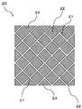
図1における粘着シート1を粘着層2側から見た平面図を図2に示す。同図に示すように、粘着層2は中央間隙部3aを介した中央粘着層2a(中央間隙部3aと中央粘着層2aとで中央領域を構成する)と、中央領域を取り囲み、外周間隙部3bを介した外周粘着層2b(外周間隙部3bと外周粘着層2bとで外周領域を構成する)とからなり、外周領域における外周間隙部3bの密度は中央領域における中央間隙部3aの密度より低く構成される。
The top view which looked at the
本実施形態では中央間隙部3aの幅と外周間隙部3bとの幅は同一にし、粘着シート1の貼着領域の外に繋がる外周間隙部3bの本数を少なく構成している。具体的には、中央粘着層2aは一辺25mmの四角形、中央間隙部3a及び外周間隙部3bの幅は0.3mm(線幅密度比で8.5対1)、外周粘着層2bの最小幅Lは2mmとした。
In the present embodiment, the width of the
また、間隙部21を介して中央粘着層22と中央粘着層22の最外周を埋める三角形状の外周粘着層23とを備えた粘着シート20を比較例として用いた。すなわち、間隙部21は本実施形態における中央間隙部3aと同じ幅で、中央粘着層22は本実施形態における中央粘着層2aと同じ面積、中央粘着層22を取り囲む外周粘着層23は中央粘着層22の半分の面積を備え、粘着シート20の外周における間隙部21の密度は中央粘着層22と同一の構成で、不図示の基材4も粘着シート1と同じ構成である。
Moreover, the
粘着シート1と粘着シート20とを筐体8に貼付し、初期特性として貼付時に入り込んだ空気に起因する空気ふくれ、経時特性としてpH12.5の塩基性界面活性剤及び中性界面活性剤をそれぞれ基材4の表面に塗布した状態で70℃、90%RH雰囲気中に100時間連続放置し、外観検査を行った。
The pressure-sensitive
初期特性として、貼付時に入り込んだ空気に起因する空気ふくれは、粘着シート1及び20共に見受けられなかった。これは、貼付時に入り込んだ空気は、粘着シート1では外周間隙部3b、粘着シート20では間隙部21を介して粘着シート1または20の貼着面積の外に追い出されるためであると想定できる。
As an initial characteristic, neither the pressure-sensitive
また、経時特性として、中性界面活性剤では粘着シート1及び20共に外観に変化はなかったが、塩基性界面活性剤では粘着シート20は間隙部21に相当する印刷層6のアルミニウム粉体が劣化し隠蔽性をなくしたのに対し、粘着シート1では印刷層6の劣化現象は見られなかった。中性界面活性剤では粘着シート1及び20共に外観変化は見られなかったが、塩基性界面活性剤による印刷層6の劣化が生じたことから、間隙部21の密度では界面活性剤が進入し隠蔽層6を浸透した塩基性成分が、印刷層6のアルミニウム粉体を劣化させたためだと想定される。
In addition, as a time-dependent characteristic, the appearance of both the pressure-sensitive
そこで、塩基性界面活性剤が間隙部21から粘着シート20の貼着面積内に進入し、隠蔽層5を浸透し印刷層6が劣化する可能性を確認するため、図4に示したように基材4と粘着層22及び23との界面に保護層7と同じポリエチレンテレフタレートフィルム保護層24(膜厚は16μm)を介在させた粘着シート30で、塩基性界面活性剤の影響を調べた。その結果、粘着シート20よりは印刷層6の劣化は少なく改善の兆しは見受けられたが、粘着シート1のレベルよりは劣っていた。
Therefore, in order to confirm the possibility that the basic surfactant enters the sticking area of the pressure-sensitive
以上の結果から、本実施形態に係る粘着シート1によれば、空気ふくれは中央間隙部3aと外周間隙部3bとを設けることで、貼付時に入り込んだ空気は粘着シート1の貼着面積の外に追い出され、しかも外周間隙部3bの密度を中央間隙部3aの密度よりも低くすることで、表面汚れを落とすクリーナーとして専ら適用されている塩基性界面活性剤に対する耐性も飛躍的に向上させることができた。
From the above results, according to the pressure-sensitive
また、反応性ガス成分としてオゾン雰囲気に10時間晒したが、粘着シート1では中央粘着層2a及び外周粘着層2bも酸化劣化が観測されなかったが、粘着シート20や30では粘着性に劣化の兆候があった。
Moreover, although it exposed to ozone atmosphere as a reactive gas component for 10 hours, neither the central
なお、中央間隙部3aと中央粘着層2aとの線幅密度比は1:2以上1:30以下が好ましい。線幅密度が1:30を越えると、中央領域の面積にもよるが、貼付の際に入り込んだ空気がふくれを発生する場合がある。また、1:2未満にすると、貼付の際に入り込んだ空気は貼付後にふくれとなることはないが、中央領域における貼着が弱く、材質のよっては基材に延びが生じる場合や粘着シート全体の貼付領域からずれが発生する場合がある。
The line width density ratio between the
また、中央間隙部3a及び外周間隙部3bの幅は、0.15mm以上1mm以下が好ましい。0.15mmよりも狭い場合には中央粘着層2a同士及び/または外周粘着層2b同士の間隙が狭いため、貼付時の基材に印加する力や温度等で間隙を塞ぐ場合があり、1mmを越えると異物が進入しやすくなる場合がある。
The widths of the
また、外周間隙部3bの外周領域における密度も、中央領域の面積にも依存するが、本実施形態のように中央領域と同様に平行な間隙部とした場合、粘着シート1の外縁における長さ比で1:350以下が好ましい。
Further, the density in the outer peripheral region of the outer
さらに、外周粘着層2bの最小幅は、本実施形態では2mmとしたが、0.5mm以上であれば反応性ガス成分や液体成分の進入は阻止することができる。
Furthermore, although the minimum width of the outer peripheral
(実施の形態2)
粘着シート1における外周間隙部3bは、中央間隙部3aと同様に隣接する外周粘着層2bが長さ方向で同じ距離(すなわち、外周間隙部3bが平行)の場合で、70℃、90%RHで100時間の条件では外見上変化は見受けられなかったが、外周間隙部3bに毛細管現象等で液体成分が蓄積することが想定されるため、図5に示した粘着シート5で外周間隙部3cを介して進入する汚染物質を想定したモデルでの経時変化も観察した。すなわち、同図に示したように、中央粘着層2a、中央間隙部3bは実施形態1と同じ構成で、外周間隙部3cの形状を中央間隙部3aと同じ幅から外周にかけて幅が狭くなる構成の粘着シート9とした。具体的には、外周間隙部3cにおける中央領域側の幅は実施形態1と同様に0.3mm、粘着シート9の外縁側における外周間隙部3cの幅を0.2mmとしたテーパー形状で、外周間隙部3cの形状に応じて外周粘着層2cの外周領域とした。なお、中央領域側における外周間隙部3cの線幅密度、外周粘着層2cの最小幅L及び基材4の構成は実施形態1と同じにした。
(Embodiment 2)
The outer
この粘着シート9を用いて、初期特性として貼付時に入り込んだ空気に起因する空気ふくれを外観で検査し、経時特性として実施形態1で用いた中性界面活性剤及び塩基性界面活性剤それぞれに墨汁を混ぜて、実施形態1と同じ条件で連続放置し、外周間隙部3c内の墨汁による汚染も確かめた。なお、本実施形態では外周間隙部3cの墨汁による汚染の有無を確かめるため、被粘着物質として筐体8とガラス基板とで行った。
Using this pressure-
本実施形態の粘着シート9でも初期特性の空気ふくれは見られなかった。また、経時特性としての印刷層6の劣化も粘着シート1と同様に見受けられなかった。なお、外周間隙部3cの墨汁による汚染度は、外周間隙部3cの外縁側先端にのみ付着の痕跡が見受けられたのに対し、粘着シート20及び30では間隙部8及び21全体で汚染が観察された。
Even in the pressure-
以上のように、本実施形態の粘着シート9では、外周間隙部3cの形状をテーパー形状としたことにより、実施形態1の効果に加え、毛細管現象で液状物質が外周間隙部3cに入り込むことを抑制する可能性が期待できる。
As described above, in the pressure-
なお、本実施形態では外縁側における外周間隙部3cの幅を0.2mmとしたが、要するに空気たまりの原因となる貼付時に入り込んだ空気を流出できれば機能を果たすことができるため、本実施の形態の幅に限定されることはない。
In this embodiment, the width of the outer
(実施の形態3)
上述の実施形態から得た知見により、外周領域に備える外周間隙部の必要性に関して検討した。すなわち、図6は本実施形態で検討した粘着シート10を粘着層側から見た平面図である。同図に示すように、中央領域における中央粘着層2a及び中央間隙部3aは実施形態1と同様の構成で、外周領域は外周粘着層2dのみの構成とした。具体的には、中央粘着層2aは一辺2.5mmの正方形、中央間隙部3aの幅は0.3mm、外周粘着層2dの最小幅Lは2mm、粘着シート10の大きさは一辺10cmの正方形とした。また、不図示の基材4の構成は実施形態1と同じである。
(Embodiment 3)
Based on the knowledge obtained from the above-described embodiment, the necessity of the outer peripheral gap provided in the outer peripheral region was examined. That is, FIG. 6 is a plan view of the pressure-
この粘着シート10を、実施形態1と同じ初期特性試験と経時特性試験とについて、視認による外観検査を行った。本実施形態では外周間隙部を省略しているため、初期特性の空気ふくれと経時特性における高温高湿環境下でのふくれが懸念されたが、ふくれ現象は全く見受けられなかった。これは、粘着シート10と筐体8との間に入り込んだ空気が中央間隙部3a全体に満遍なく広がったため、ふくれ現象が生じなかったと想定される。
The pressure-
なお、粘着シート10の大きさを一辺5cmの四分の一にしても、逆に一辺20cmの四倍としてもふくれは発生しなかった。この結果から、中央粘着層2aの大きさと中央間隙部3aの幅が一定であるため、粘着シート10の大きさに対する依存性はほぼ無視できるものと想定される。そこで、中央領域における中央間隙部3aの線幅密度を変化させた粘着シートでも検討したが、実施形態1と同様1:2以上1:30以下の範囲ではふくれは発生しなかった。
In addition, even if the size of the pressure-
また、本実施形態では外周間隙部をなくした構成であるため、反応性ガスや反応性成分を含む液体が中央間隙部3aに進入することはなく、隠蔽層5を浸透した結果印刷層6の色材が劣化するという現象は根本的に解消できた。
Further, in the present embodiment, since the outer peripheral gap portion is eliminated, the liquid containing reactive gas or reactive component does not enter the
なお、上述の実施形態ではいずれも、基材4の外縁から外周粘着層を備える構成であるため、外縁部に存在する粘着層が基材4からはみ出すことで使用者に不快感を与える場合を想定し、図7〜図9の構成でも初期特性及び経時特性の試験を行った。すなわち、図7の粘着シート11は実施形態1の粘着シート1と同じ中央領域と外周領域とを備え、外周領域のさらに外周を長さ0.5mmの基材4の面で庇を設けた構成、図8の粘着シート12は実施形態2の粘着シート9と同じ中央領域とが異種領域とを備え、外周領域のさらに外周を長さ0.5mmの基材4の面で庇を設けた構成、図9の粘着シート13は実施形態3の粘着シート10と同じ中央領域と外周領域とを備え、外周領域のさらに外周を長さ0.5mmの基材4の面で庇を設けた構成である。この粘着シート11〜13でも初期特性及び経時特性共に、それぞれ対応する実施形態と全く同じであった。なお、粘着シート11〜13では最外周に粘着層を備えない基材4の面を設けたことで、基材4に対し直交する横方向から手が触れても、粘着間は一切なく、良好な感触であった。なお、粘着シート11〜13では最外周の基材4の庇部分の幅を0.5mmとしたが、0.3mm程度でも同様の感触が得られた。なお、この庇部分の幅の上限は、外周粘着層2b、2c及び2dの最小幅、及び/または粘着シート11〜13の大きさを鑑みて決定することができる。
In any of the above-described embodiments, since the outer peripheral adhesive layer is provided from the outer edge of the
なお、上記実施形態における中央粘着層の形状は正方形としたが、正方形に限定される矩形、三角形、円形、楕円形等あらゆる形状を適用することができる。また、上記実施形態で説明した中央間隙部は全て外周領域に連設する構成として説明したが、複数の中央間隙部で閉空間を構成する形態でも適用することができることは、実施形態3からも明らかである。さらに、上記実施形態では中央粘着層の最外周が外周粘着層と繋がった例で説明したが、例えば中央粘着層の構成が図3に示した構成の更に外周に間隙を介して、外周粘着層を備えても適用することができる。また、上記実施形態では基材の一方の面のみに粘着層を備える構成で説明したが、基材の両面に備えるいわゆる両面接着シートに対しても、当然適用することができる。 In addition, although the shape of the center adhesive layer in the said embodiment was made into square, all shapes, such as a rectangle limited to a square, a triangle, a circle, and an ellipse, are applicable. In addition, the central gap portion described in the above embodiment has been described as a configuration in which all of the central gap portions are continuously provided in the outer peripheral region. However, the embodiment can also be applied to a configuration in which a closed space is constituted by a plurality of central gap portions. it is obvious. Furthermore, in the above-described embodiment, the example in which the outermost periphery of the central adhesive layer is connected to the outer peripheral adhesive layer has been described. For example, the configuration of the central adhesive layer is further increased to the outer periphery of the configuration shown in FIG. Even if it is provided, it can be applied. Moreover, although the said embodiment demonstrated by the structure provided with an adhesion layer only in one surface of a base material, naturally it can apply also to what is called a double-sided adhesive sheet provided in both surfaces of a base material.
本発明の粘着シートは、貼付時に基材と被粘着物との間に入り込む空気に起因する空気ふくれの抑制、反応性ガスや反応性物質を含有する液体に対する耐性、及び高温高湿環境下での耐性等粘着シートに要請される各種特性に優れた効果を発揮するため、例えばカーオーディオやカーナビゲーション等の車載電子機器、例えばディジタルビデオカメラ、ディジタルスチルカメラ、形態電話、ノートパソコン等使用者の手が長時間触れる電子機器等に適用することができる。 The pressure-sensitive adhesive sheet of the present invention suppresses air bulging caused by air entering between the base material and the adherend during sticking, resistance to liquids containing reactive gases and reactive substances, and in a high-temperature and high-humidity environment. In order to exert excellent effects on various properties required for adhesive sheets, such as car resistance, in-vehicle electronic devices such as car audio and car navigation, such as digital video cameras, digital still cameras, mobile phones, laptop computers, etc. The present invention can be applied to electronic devices that are touched for a long time.
1 粘着シート
2 粘着層
2a 中央粘着層
2b 外周粘着層
3 間隙部
3a 中央間隙部
3b 外周間隙部
4 基材
5 隠蔽層
6 印刷層
7 保護層
DESCRIPTION OF
Claims (3)
前記基材上で間隙部を介して選択的に粘設した中央領域と、前記中央領域を取り囲む周辺領域とを備え、
前記中央領域の前記間隙部は前記周辺領域に連通し、前記周辺領域における間隙部の密度を前記中央領域における前記間隙部の密度未満に構成した粘着シート。 An adhesive sheet provided with an adhesive layer on one main surface of the substrate,
A central region selectively adhered via a gap on the substrate, and a peripheral region surrounding the central region,
The pressure-sensitive adhesive sheet, wherein the gap in the central region communicates with the peripheral region, and the density of the gap in the peripheral region is less than the density of the gap in the central region.
Priority Applications (1)
| Application Number | Priority Date | Filing Date | Title |
|---|---|---|---|
| JP2008091091A JP2009242602A (en) | 2008-03-31 | 2008-03-31 | Self-adhesive sheet |
Applications Claiming Priority (1)
| Application Number | Priority Date | Filing Date | Title |
|---|---|---|---|
| JP2008091091A JP2009242602A (en) | 2008-03-31 | 2008-03-31 | Self-adhesive sheet |
Publications (2)
| Publication Number | Publication Date |
|---|---|
| JP2009242602A true JP2009242602A (en) | 2009-10-22 |
| JP2009242602A5 JP2009242602A5 (en) | 2010-09-16 |
Family
ID=41304888
Family Applications (1)
| Application Number | Title | Priority Date | Filing Date |
|---|---|---|---|
| JP2008091091A Pending JP2009242602A (en) | 2008-03-31 | 2008-03-31 | Self-adhesive sheet |
Country Status (1)
| Country | Link |
|---|---|
| JP (1) | JP2009242602A (en) |
Cited By (4)
| Publication number | Priority date | Publication date | Assignee | Title |
|---|---|---|---|---|
| WO2011048813A1 (en) | 2009-10-21 | 2011-04-28 | パナソニック株式会社 | Sound processing apparatus, sound processing method and hearing aid |
| WO2011148990A1 (en) * | 2010-05-26 | 2011-12-01 | 旭硝子株式会社 | Transparent surface material having adhesive layer, display device, and manufacturing method for same |
| WO2012077727A1 (en) * | 2010-12-08 | 2012-06-14 | 旭硝子株式会社 | Adhesive-layer-equipped transparent surface material, display device, and methods for producing same |
| WO2012077726A1 (en) * | 2010-12-08 | 2012-06-14 | 旭硝子株式会社 | Adhesive-layer-equipped transparent surface material, display device, and methods for producing same |
Citations (4)
| Publication number | Priority date | Publication date | Assignee | Title |
|---|---|---|---|---|
| JPS50108961U (en) * | 1974-02-19 | 1975-09-05 | ||
| JPS6451646U (en) * | 1987-09-25 | 1989-03-30 | ||
| JPH0655878A (en) * | 1992-08-10 | 1994-03-01 | Eiburii Toppan Kk | Tack paper for printer and manufacture thereof |
| JP2009119664A (en) * | 2007-11-13 | 2009-06-04 | Kokuyo Co Ltd | Adhesive sheet and its laminated body |
-
2008
- 2008-03-31 JP JP2008091091A patent/JP2009242602A/en active Pending
Patent Citations (4)
| Publication number | Priority date | Publication date | Assignee | Title |
|---|---|---|---|---|
| JPS50108961U (en) * | 1974-02-19 | 1975-09-05 | ||
| JPS6451646U (en) * | 1987-09-25 | 1989-03-30 | ||
| JPH0655878A (en) * | 1992-08-10 | 1994-03-01 | Eiburii Toppan Kk | Tack paper for printer and manufacture thereof |
| JP2009119664A (en) * | 2007-11-13 | 2009-06-04 | Kokuyo Co Ltd | Adhesive sheet and its laminated body |
Cited By (10)
| Publication number | Priority date | Publication date | Assignee | Title |
|---|---|---|---|---|
| WO2011048813A1 (en) | 2009-10-21 | 2011-04-28 | パナソニック株式会社 | Sound processing apparatus, sound processing method and hearing aid |
| WO2011148990A1 (en) * | 2010-05-26 | 2011-12-01 | 旭硝子株式会社 | Transparent surface material having adhesive layer, display device, and manufacturing method for same |
| JPWO2011148990A1 (en) * | 2010-05-26 | 2013-07-25 | 旭硝子株式会社 | Transparent surface material with adhesive layer, display device and manufacturing method thereof |
| JP5757288B2 (en) * | 2010-05-26 | 2015-07-29 | 旭硝子株式会社 | Transparent surface material with adhesive layer, display device and manufacturing method thereof |
| WO2012077727A1 (en) * | 2010-12-08 | 2012-06-14 | 旭硝子株式会社 | Adhesive-layer-equipped transparent surface material, display device, and methods for producing same |
| WO2012077726A1 (en) * | 2010-12-08 | 2012-06-14 | 旭硝子株式会社 | Adhesive-layer-equipped transparent surface material, display device, and methods for producing same |
| CN103249553A (en) * | 2010-12-08 | 2013-08-14 | 旭硝子株式会社 | Adhesive-layer-quipped transparent surface material, display device, and methods for producing same |
| JPWO2012077726A1 (en) * | 2010-12-08 | 2014-05-22 | 旭硝子株式会社 | Transparent surface material with adhesive layer, display device and manufacturing method thereof |
| JPWO2012077727A1 (en) * | 2010-12-08 | 2014-05-22 | 旭硝子株式会社 | Transparent surface material with adhesive layer, display device and manufacturing method thereof |
| US10557065B2 (en) | 2010-12-08 | 2020-02-11 | AGC Inc. | Adhesive layer-equipped transparent surface material, display device and processes for their production |
Similar Documents
| Publication | Publication Date | Title |
|---|---|---|
| TWI484878B (en) | A bonded structure, a touch display with a bonded structure and a method of fitting it | |
| JPWO2010074144A1 (en) | Protective panel with touch input function for electronic device display window and manufacturing method thereof | |
| ATE352832T1 (en) | LABEL SHEET | |
| WO2018014548A1 (en) | Light shielding tape, display device applying light shielding tape, and manufacturing method therefor | |
| CN114149756B (en) | Protective film structure and touch panel | |
| TWI522866B (en) | Display unit for touch screen and manufacturing method thereof | |
| KR20120086259A (en) | Waterproof double-sided adhesive tape | |
| JP2009242602A (en) | Self-adhesive sheet | |
| JP3181526U (en) | Display screen protection sheet | |
| TW201403418A (en) | Touch panel and method of manufacturing the same | |
| JP2009242602A5 (en) | ||
| JP2008027718A (en) | Key sheet | |
| JP2005200499A (en) | Adhesive sheet and method for producing the same | |
| JP2011042773A (en) | Perforated film sheet | |
| CN210796317U (en) | Back adhesive and electronic equipment applying same | |
| KR101460242B1 (en) | The adhesive film for fixing the module of mobile device, which has impact resistance and water resistance | |
| JP2009221380A (en) | Adhesive sheet and separate sheet-attached adhesive sheet using the same | |
| JP2010024307A (en) | Pressure-sensitive adhesive sheet | |
| JP2010090344A (en) | Method for manufacturing double-coated adhesive tape, display, and bonded substrate and method of manufacturing display | |
| JP4713196B2 (en) | Thermal adhesive label | |
| KR102108842B1 (en) | Touch Panel | |
| JP2003114620A (en) | Label sheet with protective film | |
| JP2015223785A (en) | Protective member | |
| TW201339913A (en) | Touch screen protection assembly and its manufacturing method | |
| CN215049866U (en) | Protective film for electronic product |
Legal Events
| Date | Code | Title | Description |
|---|---|---|---|
| A521 | Written amendment |
Free format text: JAPANESE INTERMEDIATE CODE: A523 Effective date: 20100804 |
|
| A621 | Written request for application examination |
Free format text: JAPANESE INTERMEDIATE CODE: A621 Effective date: 20100804 |
|
| RD01 | Notification of change of attorney |
Free format text: JAPANESE INTERMEDIATE CODE: A7421 Effective date: 20100914 |
|
| A977 | Report on retrieval |
Free format text: JAPANESE INTERMEDIATE CODE: A971007 Effective date: 20120719 |
|
| A131 | Notification of reasons for refusal |
Free format text: JAPANESE INTERMEDIATE CODE: A131 Effective date: 20120731 |
|
| A521 | Written amendment |
Free format text: JAPANESE INTERMEDIATE CODE: A523 Effective date: 20120928 |
|
| A02 | Decision of refusal |
Free format text: JAPANESE INTERMEDIATE CODE: A02 Effective date: 20121030 |