KR20130128954A - Block for an approach prevention of cars - Google Patents
Block for an approach prevention of cars Download PDFInfo
- Publication number
- KR20130128954A KR20130128954A KR1020120053189A KR20120053189A KR20130128954A KR 20130128954 A KR20130128954 A KR 20130128954A KR 1020120053189 A KR1020120053189 A KR 1020120053189A KR 20120053189 A KR20120053189 A KR 20120053189A KR 20130128954 A KR20130128954 A KR 20130128954A
- Authority
- KR
- South Korea
- Prior art keywords
- vehicle
- block
- base block
- curved
- entry
- Prior art date
Links
Images


Classifications
-
- E—FIXED CONSTRUCTIONS
- E01—CONSTRUCTION OF ROADS, RAILWAYS, OR BRIDGES
- E01F—ADDITIONAL WORK, SUCH AS EQUIPPING ROADS OR THE CONSTRUCTION OF PLATFORMS, HELICOPTER LANDING STAGES, SIGNS, SNOW FENCES, OR THE LIKE
- E01F15/00—Safety arrangements for slowing, redirecting or stopping errant vehicles, e.g. guard posts or bollards; Arrangements for reducing damage to roadside structures due to vehicular impact
- E01F15/02—Continuous barriers extending along roads or between traffic lanes
- E01F15/08—Continuous barriers extending along roads or between traffic lanes essentially made of walls or wall-like elements ; Cable-linked blocks
Abstract
The present invention relates to a vehicle entrance preventing block, wherein a lower end portion is formed to be curved outwardly in a lower portion of one surface of the base block and the base block to be installed in an installation target area, and has a greater curvature toward the rear end portion of the base block. It provides a vehicle entrance preventing block comprising a curved portion.
According to the present invention as described above, when the vehicle enters the pedestrian direction, the wheels of the entry vehicle is moved along the curved surface of the bent portion so that the direction of the entry vehicle is forward or inverted by damage or damage caused by the collision with the entry vehicle Not only can it be prevented in advance, but it is also effective in preventing safety accidents caused by entry vehicles.
Description
The present invention relates to a vehicle anti-entry block, and more particularly, when the vehicle enters the pedestrian direction, the direction of the entry vehicle is forward or inverted to prevent damage or damage due to collision with the entry vehicle. In addition, the present invention relates to an ingress prevention block for a vehicle that can prevent a safety accident caused by an ingress vehicle in advance.
In general, vehicle ingress prevention members are installed in areas where pedestrians should be protected from vehicles, such as crosswalks, road and sidewalk crossings, intersection triangle safety zones, park entrances, and bicycle lanes. When a vehicle enters a pedestrian direction due to a collision, it blocks a vehicle to enter and protects the pedestrian from the vehicle.
As the vehicle entrance preventing member, a cylindrical bollard is mainly used. An example of such a bollard is illustrated in FIG.
1 is a cross-sectional view showing a state in which a conventional bollard is installed in the installation target area.
As shown in FIG. 1, the
Such a
However, in the
In addition, the
The present invention has been made to solve the above problems, an object of the present invention is to prevent the damage or damage caused by the collision with the entry vehicle by allowing the direction of the entry vehicle to be forward or inverted when the vehicle enters the pedestrian direction. In addition, the present invention provides an in-vehicle prevention block for preventing a safety accident caused by the in-vehicle in advance.
According to an aspect of the present invention for achieving the above object, in the vehicle entrance preventing block is installed between the road and the sidewalk to prevent the vehicle from entering the side, the base block having a lower end is installed in the installation target area and It is formed to be curved outwardly in the lower portion of one side of the base block, and provides a vehicle entrance preventing block comprising a curved portion formed to have a large curvature toward the rear end of the base block.
The curved surface may further include an inclined portion formed on an upper surface of the base block on which the curved surface is formed and formed to be inclined inward from the rear of the base block to the front.
In addition, one side is attached to one side of the curved portion, the other side is coupled to the upper one side of the base block, the inner surface is installed to be spaced apart from the outer surface of the base block so that a buffer space is formed between the inner surface and the outer surface of the base block. It is preferable that the buffer plate further comprises.
In addition, it may further include an induction guide portion formed to be inclined outward from one side of the lower end of the curved portion.
Further, a front block which is installed adjacent to the base block at a location where the vehicle enters in an installation target area, the front surface into which the vehicle enters is curved in the left and right direction, and is further inclined downward from the upper end to the lower end. It is preferable.
According to the present invention as described above, when the vehicle enters the pedestrian direction, the wheels of the entry vehicle is moved along the curved surface of the bent portion so that the direction of the entry vehicle is forward or inverted by damage or damage caused by the collision with the entry vehicle Not only can it be prevented in advance, but it is also effective in preventing safety accidents caused by entry vehicles.
1 is a cross-sectional view showing a state in which a conventional bollard is installed in the installation target area;
2 is a perspective view of an entrance preventing block for a vehicle according to an embodiment of the present invention;
Figure 3 is a cross-sectional view of the vehicle entrance preventing block according to an embodiment of the present invention,
4 is a view showing a state in which the entrance vehicle is conducted by the vehicle entrance prevention block according to an embodiment of the present invention,
5 is a perspective view of an entrance preventing block for a vehicle according to another embodiment of the present invention;
6 is a view showing a state in which the entrance direction of the vehicle front side by the vehicle entrance preventing block according to another embodiment of the present invention.
Hereinafter, embodiments of the present invention will be described in detail with reference to the accompanying drawings.
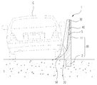
Figure 2 is a perspective view of a vehicle anti-entry block according to an embodiment of the present invention, Figure 3 is a cross-sectional view of the vehicle anti-entry block according to an embodiment of the present invention.
As shown in FIGS. 2 and 3, the vehicle entry preventing block 1 according to an exemplary embodiment of the present invention includes a
The
The
In addition, the
The
The
In addition, the
The
4 is a view showing a state in which the entrance vehicle is conducted by the vehicle entrance prevention block according to an embodiment of the present invention.
The operation of the vehicle entrance preventing block 1 according to the embodiment of the present invention having such a configuration will be described with reference to FIG. 4.
First, when a vehicle enters a pedestrian direction due to a driver's carelessness or a collision between driving vehicles, wheels of a vehicle entering in the pedestrian direction are supported on the upper surface of the
The entry vehicle enters along the
In this way, the vehicle is moved in a state supported by the
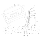
5 is a perspective view of a vehicle entrance preventing block 1 according to another embodiment of the present invention.
The basic configuration of the embodiment of FIG. 5 is the same as the embodiment of FIGS. 2 and 4, but is formed in a shape having a vertex such as an intersection triangle safety zone and is formed in a structure suitable for a pedestrian safety area in which the vehicle enters the vertex direction.
As shown in FIG. 5, the present embodiment further includes a
The
6 is a view showing a state in which the entrance direction of the vehicle to the front by the vehicle entrance preventing block according to another embodiment of the present invention.
As shown in FIG. 6, the vehicle entry preventing block 1 according to another embodiment of the present invention further includes a
Therefore, when the vehicle enters the vertex of the intersection triangular safety zone in the direction, one end of the vehicle is supported on one side of the
Accordingly, the vehicle moved in one of the left and right directions is moved in the direction of the
Although the present invention has been described in connection with the above-mentioned preferred embodiments, it is possible to make various modifications and variations without departing from the spirit and scope of the invention. Accordingly, the appended claims are intended to cover such modifications or changes as fall within the scope of the invention.
1: Vehicle entrance prevention block 10: Base block
11
20: curved portion 30: inclined portion
40: buffer plate S: buffer space
50: entry guide part 60: front block
Claims (5)
A base block having a lower end installed in an installation target area; And
And a curved portion formed to be curved outwardly under one surface of the base block, the curved portion being formed to have a large curvature toward the rear end of the base block.
And an inclined portion formed on an upper surface of the base block on which the curved surface is formed, and further comprising an inclined portion formed to be inclined outward from a front end portion of the base block toward a rear end portion.
One side is attached to one side of the curved portion, the other side is coupled to the upper one side of the base block, the inner surface is installed to be spaced apart from the outer surface of the base block buffer to form a buffer space between the inner surface and the outer surface of the base block Vehicle prevention block for the vehicle further comprises a plate.
Vehicle entry preventing block further comprises an induction induction portion formed to be inclined outward from one side of the lower end of the curved portion.
It is installed adjacent to the base block at the position where the vehicle enters in the installation target area, the front surface of the vehicle is further formed to be curved in the left and right direction, and further comprises a front block formed to be inclined downward from the upper end to the lower end direction. Ingress prevention block for vehicles.
Priority Applications (1)
| Application Number | Priority Date | Filing Date | Title |
|---|---|---|---|
| KR1020120053189A KR20130128954A (en) | 2012-05-18 | 2012-05-18 | Block for an approach prevention of cars |
Applications Claiming Priority (1)
| Application Number | Priority Date | Filing Date | Title |
|---|---|---|---|
| KR1020120053189A KR20130128954A (en) | 2012-05-18 | 2012-05-18 | Block for an approach prevention of cars |
Publications (1)
| Publication Number | Publication Date |
|---|---|
| KR20130128954A true KR20130128954A (en) | 2013-11-27 |
Family
ID=49855928
Family Applications (1)
| Application Number | Title | Priority Date | Filing Date |
|---|---|---|---|
| KR1020120053189A KR20130128954A (en) | 2012-05-18 | 2012-05-18 | Block for an approach prevention of cars |
Country Status (1)
| Country | Link |
|---|---|
| KR (1) | KR20130128954A (en) |
Cited By (3)
| Publication number | Priority date | Publication date | Assignee | Title |
|---|---|---|---|---|
| KR102172805B1 (en) | 2020-05-11 | 2020-11-02 | 안창선 | Bag or wallet storage and coin sterilizer |
| KR102330447B1 (en) | 2020-05-26 | 2021-11-24 | 주식회사 두리트레이더스 | Desk dividers |
| KR20220082186A (en) | 2020-12-10 | 2022-06-17 | 한세준 | The portable battery type UV-LED sterilizer |
-
2012
- 2012-05-18 KR KR1020120053189A patent/KR20130128954A/en not_active Application Discontinuation
Cited By (3)
| Publication number | Priority date | Publication date | Assignee | Title |
|---|---|---|---|---|
| KR102172805B1 (en) | 2020-05-11 | 2020-11-02 | 안창선 | Bag or wallet storage and coin sterilizer |
| KR102330447B1 (en) | 2020-05-26 | 2021-11-24 | 주식회사 두리트레이더스 | Desk dividers |
| KR20220082186A (en) | 2020-12-10 | 2022-06-17 | 한세준 | The portable battery type UV-LED sterilizer |
Similar Documents
| Publication | Publication Date | Title |
|---|---|---|
| US9902225B2 (en) | Cover for a chassis control arm | |
| CN210737371U (en) | Rail guard based on road and bridge design | |
| KR20130128954A (en) | Block for an approach prevention of cars | |
| CN204455915U (en) | A kind of highway barrier with traffic indication board | |
| KR200414622Y1 (en) | Indication bar for road boundary | |
| RU2685963C2 (en) | Facing unit for vehicle (options) and method for strengthening elastic facing element | |
| KR101507481B1 (en) | Median strip for shock absorber | |
| KR200387087Y1 (en) | Impact suction apparatus using guide rail | |
| KR20130132194A (en) | Road signal marker | |
| KR101703944B1 (en) | installation structure of glare shield for median strip | |
| KR20100042697A (en) | Safety guardrail for protecting driver and providing construction convenience | |
| KR100457890B1 (en) | Shock guard road guardrail | |
| KR200268035Y1 (en) | Enhanced Central Separator | |
| KR200298063Y1 (en) | A Median Strip for a Road | |
| KR101256872B1 (en) | Median strip for road | |
| KR101197137B1 (en) | Car stopper for parking | |
| KR200248423Y1 (en) | Shock-Reducing Guide Rails | |
| JPH0647933Y2 (en) | Wall protection material with induction sign | |
| KR100964549B1 (en) | Driver danger catch mat for driveway | |
| JP5142961B2 (en) | Protective fence | |
| KR20100086137A (en) | Eye inducement device attached to guard rail | |
| KR200283344Y1 (en) | Shock-absorbing guide rail | |
| KR101869058B1 (en) | Guard rail for multistage shock absorption by rail having vertically asymmetrical shape | |
| KR200201560Y1 (en) | Study-type guide box for central road line | |
| KR20150122989A (en) | Fences for Bicycle Parking Lot |
Legal Events
| Date | Code | Title | Description |
|---|---|---|---|
| A201 | Request for examination | ||
| E902 | Notification of reason for refusal | ||
| E601 | Decision to refuse application |