KR20130110655A - System for compensating error of work machine spindle - Google Patents
System for compensating error of work machine spindle Download PDFInfo
- Publication number
- KR20130110655A KR20130110655A KR1020120032784A KR20120032784A KR20130110655A KR 20130110655 A KR20130110655 A KR 20130110655A KR 1020120032784 A KR1020120032784 A KR 1020120032784A KR 20120032784 A KR20120032784 A KR 20120032784A KR 20130110655 A KR20130110655 A KR 20130110655A
- Authority
- KR
- South Korea
- Prior art keywords
- spindle
- error
- displacement
- actuator
- tool holder
- Prior art date
Links
Images


Classifications
-
- B—PERFORMING OPERATIONS; TRANSPORTING
- B23—MACHINE TOOLS; METAL-WORKING NOT OTHERWISE PROVIDED FOR
- B23Q—DETAILS, COMPONENTS, OR ACCESSORIES FOR MACHINE TOOLS, e.g. ARRANGEMENTS FOR COPYING OR CONTROLLING; MACHINE TOOLS IN GENERAL CHARACTERISED BY THE CONSTRUCTION OF PARTICULAR DETAILS OR COMPONENTS; COMBINATIONS OR ASSOCIATIONS OF METAL-WORKING MACHINES, NOT DIRECTED TO A PARTICULAR RESULT
- B23Q15/00—Automatic control or regulation of feed movement, cutting velocity or position of tool or work
- B23Q15/007—Automatic control or regulation of feed movement, cutting velocity or position of tool or work while the tool acts upon the workpiece
- B23Q15/14—Control or regulation of the orientation of the tool with respect to the work
-
- B—PERFORMING OPERATIONS; TRANSPORTING
- B23—MACHINE TOOLS; METAL-WORKING NOT OTHERWISE PROVIDED FOR
- B23Q—DETAILS, COMPONENTS, OR ACCESSORIES FOR MACHINE TOOLS, e.g. ARRANGEMENTS FOR COPYING OR CONTROLLING; MACHINE TOOLS IN GENERAL CHARACTERISED BY THE CONSTRUCTION OF PARTICULAR DETAILS OR COMPONENTS; COMBINATIONS OR ASSOCIATIONS OF METAL-WORKING MACHINES, NOT DIRECTED TO A PARTICULAR RESULT
- B23Q17/00—Arrangements for observing, indicating or measuring on machine tools
- B23Q17/22—Arrangements for observing, indicating or measuring on machine tools for indicating or measuring existing or desired position of tool or work
- B23Q17/2216—Arrangements for observing, indicating or measuring on machine tools for indicating or measuring existing or desired position of tool or work for adjusting the tool into its holder
- B23Q17/2225—Arrangements for observing, indicating or measuring on machine tools for indicating or measuring existing or desired position of tool or work for adjusting the tool into its holder with the toolholder as reference-element
-
- B—PERFORMING OPERATIONS; TRANSPORTING
- B23—MACHINE TOOLS; METAL-WORKING NOT OTHERWISE PROVIDED FOR
- B23Q—DETAILS, COMPONENTS, OR ACCESSORIES FOR MACHINE TOOLS, e.g. ARRANGEMENTS FOR COPYING OR CONTROLLING; MACHINE TOOLS IN GENERAL CHARACTERISED BY THE CONSTRUCTION OF PARTICULAR DETAILS OR COMPONENTS; COMBINATIONS OR ASSOCIATIONS OF METAL-WORKING MACHINES, NOT DIRECTED TO A PARTICULAR RESULT
- B23Q5/00—Driving or feeding mechanisms; Control arrangements therefor
- B23Q5/02—Driving main working members
- B23Q5/04—Driving main working members rotary shafts, e.g. working-spindles
- B23Q5/20—Adjusting or stopping working-spindles in a predetermined position
Abstract
Description
본 발명은 가공기의 스핀들 오차 보상 시스템에 관한 것으로, 보다 상세하게는 스핀들의 회전시 발생되는 오차를 실시간으로 측정하여 그 측정된 오차를 보상하도록 툴(tool)이 장착된 툴 홀더(tool holder)를 이동시킴으로써 스핀들의 운동운동오차를 실시간으로 보정할 수 있는 가공기의 스핀들 오차 보상 시스템에 관한 것이다.The present invention relates to a spindle error compensation system of a machine, and more particularly to a tool holder equipped with a tool (tool) to measure the error generated when the spindle rotates in real time to compensate for the measured error. The present invention relates to a spindle error compensation system of a machine that can correct the movement error of the spindle by moving.
일반적으로 가공물의 가공에는 절삭 툴(tool)을 이용하는 선반, 밀링머신과 같은 가공기가 많이 이용된다. 일반적으로 가공기는 가공물의 회전을 위한 회전계와, 툴(tool)의 이송을 위한 이송계가 구비되어 구성되는데, 도 6은 대표적인 가공기의 하나인 선반을 도시한 것이다. 도 6을 참조하면, 일반인 선반은 크게 베드(bed)(10), 주축대(headstock)(20), 왕복대(carriage)(30), 심압대(tailstock)(40) 및 기타 부속장치로 구성된다. 상기 주축대(20)에는 전동기의 동력을 받아 회전하는 주축(主軸; spindle)과, 주축의 나사부에 가공물을 고정하는 척(chuck)(22) 또는 면판(面板; face plate)이 설치되며, 툴홀더(31)가 구비된 왕복대(30)를 베드(10)를 따라 이동시키며 회전하는 가공물을 툴로 절삭가공, 나사가공, 테이퍼가공, 널링가공, 드릴링가공, 보오링가공 등을 하게 된다. 상기 선반에서는 주축(스핀들)을 포함한 주축대가 회전계에 해당되며, 툴의 이송을 위한 이송대가 이송계에 해당된다.In general, a machine such as a lathe and a milling machine using a cutting tool is widely used for processing a workpiece. In general, the machine is provided with a rotation system for the rotation of the workpiece, and a feed system for the transfer of the tool (tool), Figure 6 shows a lathe which is one of the representative processing machines. Referring to Figure 6, the general public shelf is composed of a bed (10), headstock (20), carriage (30), tailstock (40) and other accessories do. The
한편, 단결정 다이아몬드 바이트를 이용하는 초정밀 가공기에서는 스핀들, 이송계 등의 주요 부품의 운동 특성이 가공정밀도에 미치는 영향이 매우 크므로 보다 높은 가공정밀도를 실현하기 위해서는 각각의 요소부품의 운동 정밀도 향상과 더불어 운동 오차의 실시간 보상이 절대적으로 요구된다. 특히 최근 초정밀 가공기에서는 가공가능한 가공물의 직경이 커지면서 각 슬라이드의 행정거리가 수백mm로 상대적으로 길어짐에도 불구하고 높은 가공정밀도가 요청되는 추세에 따라 nm 수준의 높은 분해능과 전 운동구간에 걸쳐 높은 운동정밀도가 요구되고 있다.On the other hand, in the ultra-precision machine using single crystal diamond bite, the movement characteristics of major parts such as spindles and feed systems have a great influence on the machining precision. Therefore, in order to realize higher machining precision, the movement precision of each element part is improved and Real time compensation of the error is absolutely required. In particular, in recent ultra-precision machines, despite the relatively long stroke length of several slides as the diameter of the workable workpiece increases, a high processing precision is required, resulting in high resolution at the nm level and high motion precision over the entire range of motion. Is required.
그러나 이송계의 관성질량이 매우 크기 때문에 이송계 전체를 이동시켜 스핀들의 운동오차를 실시간으로 보상하기에는 응답속도가 늦어져 실시간 운동오차 보상이 매우 어렵게 된다. 이로 인하여 각 요소부품의 정밀도를 향상시킬 수밖에 없어 가공기의 제작비용이 크게 증가하게 되고, 수 m 에 달하는 스핀들의 축방향 운동오차, 이송계의 운동오차, 가공물의 변형 등에 의해 가공정밀도에 한계를 가질 수밖에 없다.However, since the inertial mass of the feed system is very large, the response speed is slow to compensate for the movement error of the spindle in real time by moving the whole feed system, making it very difficult to compensate the motion error in real time. As a result, the precision of each component is inevitably improved, and the manufacturing cost of the machine is greatly increased, and the machining precision may be limited due to the axial movement error of the spindle, the movement error of the feed system, and the deformation of the workpiece. There is no choice but to.
본 발명은 상기와 같은 문제점을 인식하여 안출된 것으로 본 발명의 목적은 스핀들의 회전시 발생되는 오차를 실시간으로 측정하여 그 측정된 오차를 보상하도록 툴(tool)이 장착된 툴 홀더(tool holder)를 이동시킴으로써 스핀들의 운동운동오차를 실시간으로 보정할 수 있는 가공기의 스핀들 오차 보상 시스템을 제공하기 위한 것이다.The present invention was conceived by recognizing the above problems, and an object of the present invention is to measure in real time an error generated during rotation of a spindle, and a tool holder equipped with a tool to compensate for the measured error. It is to provide a spindle error compensation system of a machine that can correct the movement error of the spindle in real time by moving.
상기와 같은 목적을 달성하기 위하여 본 발명에 따른 가공기의 스핀들 오차 보상 시스템은, 스핀들의 회전으로 가공물을 회전시키기 위한 회전계와, 툴홀더에 장착된 툴을 이송시키기 위한 이송계가 구비된 가공기의 스핀들의 오차를 측정하여 그 측정된 오차를 보상하도록 툴홀더를 이동시키기 위한 가공기의 스핀들 오차 보상 시스템에 있어서, 상기 회전계에는, 스핀들의 오차변위를 측정하기 위한 변위측정센서가 구비되고, 상기 이송계에는, 상기 툴홀더를 이동시키기 위한 액츄에이터가 구비되며, 상기 변위측정센서에 의해 측정된 오차변위값에 따라 상기 툴홀더의 보상변위값을 산출하고 그에 따라 상기 액츄에이터가 툴홀더를 이동시키도록 상기 액츄에이터의 작동을 제어하는 제어부가 더 구비된 것을 특징으로 한다.In order to achieve the above object, a spindle error compensation system of a machine according to the present invention includes a rotation system for rotating a workpiece by rotation of a spindle, and a spindle of a machine equipped with a feed system for transferring a tool mounted on a tool holder. In the spindle error compensation system of the machine for moving the tool holder to measure the error and compensate the measured error, the rotation system is provided with a displacement measuring sensor for measuring the error displacement of the spindle, An actuator is provided for moving the tool holder, and the compensation displacement value of the tool holder is calculated according to the error displacement value measured by the displacement measuring sensor, and the actuator is operated to move the tool holder accordingly. It is characterized in that the control unit for controlling the further provided.
또한, 본 발명에 따른 가공기의 스핀들 오차 보상 시스템은, 상기 변위측정센서는, 상기 스핀들의 축방향과 연직인 스핀들의 수평방향의 오차변위를 감지하기 위한 수평방향 변위측정센서와, 상기 스핀들의 축방향과 연직인 스핀들의 상하방향 오차변위를 감지하기 위한 상하방향 변위측정센서와, 상기 스핀들의 축방향 오차변위를 감지하기 위한 축방향 변위측정센서로 구성되고, 상기 툴홀더는, X-Y 방향 이동블럭과 Z 방향 이동블럭으로 분할되어 구성되되, 상기 Z 방향 이동블럭은 X-Y 방향 이동블럭의 X-Y 방향 이동시 X-Y 방향 이동블럭과 함께 X-Y 방향으로 이동되며, 상기 액츄에이터는, 상기 X-Y 방향 이동블럭을 X 방향으로 이동시키는 X 방향 이동 액츄에이터와, 상기 X-Y 방향 이동블럭을 Y 방향으로 이동시키는 Y 방향 이동 액츄에이터와, 상기 Z 방향 이동블럭을 상기 상기 X-Y 방향 이동블럭에 대하여 상대적으로 Z 방향으로 이동시키는 Z 방향 이동 액츄에이터로 구성된 것을 특징으로 한다.In addition, the spindle error compensation system of the machine according to the present invention, the displacement measuring sensor, a horizontal displacement measuring sensor for detecting the error displacement in the horizontal direction of the spindle perpendicular to the axial direction of the spindle, and the axis of the spindle It consists of an up-down displacement measuring sensor for detecting the vertical error displacement of the spindle perpendicular to the direction, and an axial displacement measuring sensor for detecting the axial error displacement of the spindle, the tool holder, XY direction movement block And the Z direction moving block, wherein the Z direction moving block moves in the XY direction together with the XY direction moving block when the XY direction moving block moves in the XY direction, and the actuator moves the XY direction moving block in the X direction. An X-direction moving actuator for moving, a Y-direction moving actuator for moving the XY-direction moving block in the Y direction, and the Z direction And a Z-direction movement actuator for moving the movement block in the Z direction relative to the X-Y direction movement block.
또한, 본 발명에 따른 가공기의 스핀들 오차 보상 시스템은, 상기 변위측정센서는, 비접촉식 갭센서로 구성된 것을 특징으로 한다.In addition, the spindle error compensation system of the processing machine according to the present invention, the displacement measuring sensor is characterized in that it is composed of a non-contact gap sensor.
또한, 본 발명에 따른 가공기의 스핀들 오차 보상 시스템은, 상기 액츄에이터는, 압전구동기로 구성된 것을 특징으로 한다.In addition, the spindle error compensation system of the machine according to the present invention, the actuator is characterized in that it is composed of a piezoelectric actuator.
상기와 같은 구성에 의하여 본 발명에 따른 가공기의 스핀들 오차 보상 시스템은, 스핀들의 회전시 발생되는 오차를 실시간으로 측정하여 그 측정된 오차를 보상하도록 툴(tool)이 장착된 툴 홀더(tool holder)를 이동시킴으로써 스핀들의 운동운동오차를 실시간으로 보정할 수 있는 장점을 갖는다.According to the above configuration, the spindle error compensation system of the machine according to the present invention includes a tool holder equipped with a tool to measure the error generated when the spindle rotates in real time and compensate for the measured error. By moving, the movement error of the spindle can be corrected in real time.
도 1은 본 발명의 일실시예에 따른 가공기의 스핀들 오차 보상 시스템을 개념적으로 도시한 구성도
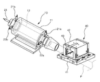
도 2는 본 발명의 일실시예에 따른 가공기의 스핀들 오차 보상 시스템의 개념적으로 사시도
도 3은 본 발명의 일실시예에 따른 가공기의 스핀들 오차 보상 시스템의 툴홀더를 도시한 사시도
도 4 및 도 5는 본 발명의 일실시예에 따른 가공기의 스핀들 오차 보상 시스템의 작동을 개념적으로 도시한 도면
도 6은 가공기의 일예로서 일반적인 선반의 구조를 도시한 사시도1 is a block diagram conceptually showing a spindle error compensation system of a machine according to an embodiment of the present invention
Figure 2 is a conceptual perspective view of the spindle error compensation system of the machine according to an embodiment of the present invention
Figure 3 is a perspective view showing a tool holder of the spindle error compensation system of the machine according to an embodiment of the present invention
4 and 5 conceptually show the operation of the spindle error compensation system of the machine according to an embodiment of the present invention.
6 is a perspective view showing the structure of a general lathe as an example of a processing machine;
이하에서는 도면에 도시된 실시예를 참조하여 본 발명에 따른 가공기의 스핀들 오차 보상 시스템을 보다 상세하게 설명하기로 한다.Hereinafter, with reference to the embodiment shown in the drawings will be described in more detail the spindle error compensation system of the machine according to the present invention.
도 1은 본 발명의 일실시예에 따른 가공기의 스핀들 오차 보상 시스템을 개념적으로 도시한 구성도이고, 도 2는 본 발명의 일실시예에 따른 가공기의 스핀들 오차 보상 시스템의 개념적으로 사시도이며, 도 3은 본 발명의 일실시예에 따른 가공기의 스핀들 오차 보상 시스템의 툴홀더를 도시한 사시도이고, 도 4 및 도 5는 본 발명의 일실시예에 따른 가공기의 스핀들 오차 보상 시스템의 작동을 개념적으로 도시한 도면이다.1 is a configuration diagram conceptually showing a spindle error compensation system of a machine according to an embodiment of the present invention, Figure 2 is a conceptual perspective view of a spindle error compensation system of a machine according to an embodiment of the present invention, 3 is a perspective view showing a tool holder of the spindle error compensation system of the machine according to an embodiment of the present invention, Figures 4 and 5 conceptually the operation of the spindle error compensation system of the machine according to an embodiment of the present invention. Figure is shown.
본 발명에 따른 가공기의 스핀들 오차 보상 시스템은 하우징(11)에 지지되어 회전되는 스핀들(12)의 회전으로 가공물(P)을 회전시키기 위한 회전계(10)와, 툴홀더(40)에 장착된 툴(43)을 이송시키기 위한 이송계가 구비된 가공기의 스핀들(12)의 오차를 측정하여 그 측정된 오차를 보상하도록 툴홀더(40)를 이동시킴으로써 스핀들(12)의 회전 오차를 보상할 수 있는 시스템이다.Spindle error compensation system of the machine according to the present invention is a
도면을 참조하면, 본 발명에 따른 가공기의 스핀들 오차 보상 시스템은 변위측정센서(21a,21b,22a,22b,23), 액츄에이터(32,33,34) 및 제어부(25)를 포함하여 구성된다.Referring to the drawings, the spindle error compensation system of the machine according to the present invention includes a displacement measuring sensor (21a, 21b, 22a, 22b, 23), actuators (32, 33, 34) and the
상기 변위측정센서(21a,21b,22a,22b,23)는 상기 스핀들(12)의 오차변위를 측정하기 위한 구성으로 상기 회전계(10)에 구비된다. 도면을 참조하면, 상기 변위측정센서(21a,21b,22a,22b,23)는 상기 스핀들(12)의 축방향과 연직인 스핀들(12)의 수평방향의 오차변위를 감지하기 위한 수평방향 변위측정센서(22a,22b)와, 상기 스핀(12)들의 축방향과 연직인 스핀들(12)의 상하방향 오차변위를 감지하기 위한 상하방향 변위측정센서(21a,21b)와, 상기 스핀들(12)의 축방향 오차변위를 감지하기 위한 축방향 변위측정센서(23)로 구성된다. 한편, 도면에는 상기 수평방향 변위측정센서(22a,22b)와 연직방향 변위측정센서(21a,21b)가 각각 한 쌍이 구비되어 스핀들(12)의 전단부와 후단부에 위치된 실시예가 도시되어 있는데 이는 스핀들(12)의 직선이동변위뿐만 아니라 회전이동변위를 측정할 수 있도록 하기 위한 것이다. 본 발명은 도면에 도시된 바와 같이 가공기의 회전체, 즉 스핀들(12)을 대상체(target)로 하여 가공기의 하우징(11) 부위에 5개의 변위측정센서(21a,21b,22a,22b,23)를 장착하고 5개의 변위측정센서(21a,21b,22a,22b,23)를 사용하여 스핀들(12)의 회전 운동정도를 측정하고 스핀들(12) 중심의 운동양상을 점군으로 측정하고 오차 데이터를 산출하여 스핀들(12)의 오차를 보상하도록 툴홀더(40)를 이동시킨다.The displacement measuring
한편, 변위를 측정할 수 있는 센서는 접촉식과 비접촉식으로 구분할 수가 있는데, 접촉식의 경우는 피측정체의 표면이 손상이 될 염려가 있거나 작은 접촉압력에 의해서도 변형이 일어날 염려가 있는 경우에는 사용이 제한되기 때문에 본 발명은 비접촉식 갭센서를 이용하는 것이 바람직하다. 스핀들(12)의 미소의 변위를 비접촉식으로 정확하게 측정할 수 있는 갭센서로는 와전류, 초음파, 광, 레이저, 적외선, 자기저항, 전기용량 등을 이용한 것이 있으며, 이 중에서 전기용량을 이용한 비접촉센서는 비교적 구조가 간단하고, 소형 경량으로 제작가능하기 때문에 적합하다.On the other hand, sensors capable of measuring displacement can be classified into contact and non-contact types. In case of contact type, the sensor may be damaged if the surface of the object is damaged or deformation may be caused by small contact pressure. Since the present invention is limited, it is preferable to use a non-contact gap sensor. As a gap sensor that can accurately measure the displacement of the
상기 액츄에이터(32,33,34)는 툴(43)을 X-Y 방향 및 Z- 방향이동시키기 위한 구성이다. The
본 발명은 이송대를 포함하여 관성질량이 큰 이송계 전체를 이동시키지 않고 비교적 관성질량이 작은 툴홀더(40)만을 이동시키도록 구성된다. 이를 위하여 상기 툴(43)이 장착되는 툴홀더(40)는 X-Y 방향 이동블럭(41)과 Z 방향 이동블럭(42)으로 분할되어 구성된다. 상기 X-Y 방향 이동블럭(41)은 상기 툴(43)을 X-Y 방향으로 이동시키기 위하여 X-Y방향으로 이동되게 이송계의 이송대와 같은 부분에 장착된다. 상기 Z방향 이동블럭(42)은 상기 상기 X-Y 방향 이동블럭(41)에 대하여 상대적으로 Z 방향으로 이동되는 구성이며, 상기 X-Y 방향 이동블럭(41)의 X-Y 방향 이동시에는 X-Y 방향 이동블럭(41)과 함께 X-Y 방향으로 이동되게 상기 X-Y 방향 이동블럭(41)의 상부에 장착된다.The present invention is configured to move only the
상술한 바와 같이 상기 액츄에이터(32,33,34)는 상기 툴홀더(40)의 X-Y 방향 이동블럭(41)과 Z 방향 이동블럭(42)을 각각 X-Y 방향과 Z 방향으로 이동시키기 위한 구성이다. 즉, 상기 액츄에이터(32,33,34)는 상기 X-Y 방향 이동블럭(41)을 X 방향으로 이동시키는 X 방향 이동 액츄에이터(32)와, 상기 X-Y 방향 이동블럭(41)을 Y 방향으로 이동시키는 Y 방향 이동 액츄에이터(33)와, 상기 Z 방향 이동블럭(42)을 상기 X-Y 방향 이동블럭(41)에 대하여 상대적으로 Z 방향으로 이동시키는 Z 방향 이동 액츄에이터(34)로 구성된다. 특히, 상기 액츄에이터로는 상대적으로 질량이 매우 적은 절삭공구와 툴홀더만을 미세하게 구동시킬 수 있도록 압전구동기(Piezo actuator)로 구성되는 것이 바람직하다.As described above, the
상기 제어부(25)는 상기 변위측정센서(21a,21b,22a,22b,23)에 의해 측정된 오차변위값(e1,e2,e3)에 따라 상기 툴홀더(40)의 보상변위값(c1,c2,c3)을 산출하고 그에 따라 상기 액츄에이터(32,33,34)가 툴홀더를 이동시키도록 상기 액츄에이터(32,33,34)의 작동을 제어하기 위한 구성이다. 상기 변위측정센서(21a,21b,22a,22b,23)에 의해 측정된 오차변위값(e1,e2,e3)은 변위감지부(24)에서 신호처리되어 상기 제어부(25)로 입력된다. 상기 제어부(25)는 입력된 오차변위값(e1,e2,e3)에 따라 상기 툴홀더(40)의 보상변위값(c1,c2,c3)을 산출하고 그에 따라 상기 액츄에이터(32,33,34)의 제어신호를 출력하게 되고 그 제어신호는 구동기증폭부(31)에 의해 증폭되어 상기 액츄에이터(32,33,34)의 구동을 제어하도록 전달된다.The
도 4 및 도 5는 본 발명의 일실시예에 따른 가공기의 스핀들 오차 보상 시스템의 작동을 개념적으로 도시한 도면이다. 도 4를 참조하면, 스핀들(11)의 회전으로 축방향 변위오차(e1)이 축방향 변위감지센서(23)에 의해 감지되면 상기 제어부(25)는 축방향 변위오차(e1)에 따라 X 방향 보상변위(c1)을 산출하여 그에 따라 X 방향 이동 액츄에이터(32)를 구동시켜 상기 X-Y 방향 이동블럭(41)을 Xc 방향으로 이동시킴으로써 결과적으로 툴(43)이 이동되어 스핀들(12)의 축방향 오차를 보상하게 된다. 또한, 도 4를 참조하면, 스핀들(11)의 회전으로 수평방향 변위오차(e2)이 수평방향 변위감지센서(22a,22b)에 의해 감지되면 상기 제어부(25)는 수평방향 변위오차(e2)에 따라 Y 방향 보상변위(c2)을 산출하여 그에 따라 Y 방향 이동 액츄에이터(33)를 구동시켜 상기 X-Y 방향 이동블럭(41)을 Yc 방향으로 이동시킴으로써 결과적으로 툴(43)이 이동되어 스핀들(12)의 수평방향 오차를 보상하게 된다. 마지막으로 도 5를 참조하면, 스핀들(11)의 회전으로 상하방향 변위오차(e3)이 상하방향 변위감지센서(21a,21b)에 의해 감지되면 상기 제어부(25)는 상하방향 변위오차(e3)에 따라 Z 방향 보상변위(c3)을 산출하여 그에 따라 Z 방향 이동 액츄에이터(34)를 구동시켜 상기 Z 방향 이동블럭(41)을 Zc 방향으로 이동시킴으로써 결과적으로 툴(43)이 이동되어 스핀들(12)의 수평방향 오차를 보상하게 된다.4 and 5 conceptually show the operation of the spindle error compensation system of the machine according to the embodiment of the present invention. Referring to FIG. 4, when the axial displacement error e1 is detected by the
앞에서 설명되고, 도면에 도시된 가공기의 스핀들 오차 보상 시스템은 본 발명을 실시하기 위한 하나의 실시예에 불과하며, 본 발명의 기술적 사상을 한정하는 것으로 해석되어서는 안된다. 본 발명의 보호범위는 이하의 특허청구범위에 기재된 사항에 의해서만 정하여지며, 본 발명의 요지를 벗어남이 없이 개량 및 변경된 실시예는 본 발명이 속하는 기술분야에서 통상의 지식을 가진 자에게 자명한 것인 한 본 발명의 보호범위에 속한다고 할 것이다. The spindle error compensation system of the machine described above and illustrated in the drawings is only one embodiment for carrying out the present invention, and should not be construed as limiting the technical idea of the present invention. The scope of protection of the present invention is defined only by the matters set forth in the claims below, and the embodiments which have been improved and changed without departing from the gist of the present invention will be apparent to those skilled in the art. It will be said to belong to the protection scope of the present invention.
12 스핀들
21a,21b,22a,22b,23 변위감지센서
25 제어부
32,33,34 액츄에이터
40 툴홀더
41 X-Y 방향 이동블럭
42 Z 방향 이동블럭12 spindle
21a, 21b, 22a, 22b, 23 displacement sensor
25 control unit
32,33,34 actuator
40 toolholder
41 XY direction moving block
42 Z direction movement block
Claims (4)
상기 회전계에는, 스핀들의 오차변위를 측정하기 위한 변위측정센서가 구비되고,
상기 이송계에는, 상기 툴홀더를 이동시키기 위한 액츄에이터가 구비되며,
상기 변위측정센서에 의해 측정된 오차변위값에 따라 상기 툴홀더의 보상변위값을 산출하고 그에 따라 상기 액츄에이터가 툴홀더를 이동시키도록 상기 액츄에이터의 작동을 제어하는 제어부가 더 구비된 것을 특징으로 하는 가공기의 스핀들 오차 보상 시스템.Spindle of the machine for moving the tool holder to measure the error of the spindle of the machine equipped with a rotation system for rotating the workpiece by the rotation of the spindle, and a feeder for transferring the tool mounted on the tool holder to compensate the measured error In the error compensation system,
The rotation system is provided with a displacement measuring sensor for measuring the error displacement of the spindle,
The transfer system is provided with an actuator for moving the tool holder,
And a control unit for calculating a compensation displacement value of the tool holder according to the error displacement value measured by the displacement measuring sensor and controlling the operation of the actuator so that the actuator moves the tool holder accordingly. Spindle error compensation system of the machine.
상기 변위측정센서는, 상기 스핀들의 축방향과 연직인 스핀들의 수평방향의 오차변위를 감지하기 위한 수평방향 변위측정센서와, 상기 스핀들의 축방향과 연직인 스핀들의 상하방향 오차변위를 감지하기 위한 상하방향 변위측정센서와, 상기 스핀들의 축방향 오차변위를 감지하기 위한 축방향 변위측정센서로 구성되고,
상기 툴홀더는, X-Y 방향 이동블럭과 Z 방향 이동블럭으로 분할되어 구성되되, 상기 Z 방향 이동블럭은 X-Y 방향 이동블럭의 X-Y 방향 이동시 X-Y 방향 이동블럭과 함께 X-Y 방향으로 이동되며,
상기 액츄에이터는, 상기 X-Y 방향 이동블럭을 X 방향으로 이동시키는 X 방향 이동 액츄에이터와, 상기 X-Y 방향 이동블럭을 Y 방향으로 이동시키는 Y 방향 이동 액츄에이터와, 상기 Z 방향 이동블럭을 상기 상기 X-Y 방향 이동블럭에 대하여 상대적으로 Z 방향으로 이동시키는 Z 방향 이동 액츄에이터로 구성된 것을 특징으로 하는 가공기의 스핀들 오차 보상 시스템.The method of claim 1,
The displacement measuring sensor may include a horizontal displacement measuring sensor for detecting an error displacement in a horizontal direction of the spindle perpendicular to the axial direction of the spindle, and an upward and downward error displacement of the spindle perpendicular to the axial direction of the spindle. A vertical displacement measuring sensor and an axial displacement measuring sensor for detecting an axial error displacement of the spindle,
The tool holder is divided into an XY direction moving block and a Z direction moving block, wherein the Z direction moving block moves in the XY direction together with the XY direction moving block when the XY direction moving block moves in the XY direction.
The actuator includes an X-direction moving actuator for moving the XY-direction moving block in the X direction, a Y-direction moving actuator for moving the XY-direction moving block in the Y direction, and the Z-direction moving block for the XY direction moving block. Spindle error compensation system of a machine, characterized in that consisting of a Z-direction movement actuator to move relative to the Z direction.
상기 변위측정센서는, 비접촉식 갭센서로 구성된 것을 특징으로 하는 가공기의 스핀들 오차 보상 시스템.3. The method according to claim 1 or 2,
The displacement measuring sensor is a spindle error compensation system of the machine, characterized in that consisting of a non-contact gap sensor.
상기 액츄에이터는, 압전구동기로 구성된 것을 특징으로 하는 가공기의 스핀들 오차 보상 시스템.3. The method according to claim 1 or 2,
The actuator is a spindle error compensation system of the machine, characterized in that consisting of a piezoelectric actuator.
Priority Applications (1)
| Application Number | Priority Date | Filing Date | Title |
|---|---|---|---|
| KR1020120032784A KR101358363B1 (en) | 2012-03-30 | 2012-03-30 | Apparatus for compensating error of work machine spindle |
Applications Claiming Priority (1)
| Application Number | Priority Date | Filing Date | Title |
|---|---|---|---|
| KR1020120032784A KR101358363B1 (en) | 2012-03-30 | 2012-03-30 | Apparatus for compensating error of work machine spindle |
Publications (2)
| Publication Number | Publication Date |
|---|---|
| KR20130110655A true KR20130110655A (en) | 2013-10-10 |
| KR101358363B1 KR101358363B1 (en) | 2014-02-07 |
Family
ID=49632440
Family Applications (1)
| Application Number | Title | Priority Date | Filing Date |
|---|---|---|---|
| KR1020120032784A KR101358363B1 (en) | 2012-03-30 | 2012-03-30 | Apparatus for compensating error of work machine spindle |
Country Status (1)
| Country | Link |
|---|---|
| KR (1) | KR101358363B1 (en) |
Cited By (3)
| Publication number | Priority date | Publication date | Assignee | Title |
|---|---|---|---|---|
| CN106002489A (en) * | 2016-07-07 | 2016-10-12 | 上海师范大学 | Automatic compensation device and method for eliminating cutting chatter of numerical control machine tool |
| CN107036553A (en) * | 2017-05-04 | 2017-08-11 | 哈尔滨工业大学 | A kind of standard for being used to measure Errors in Radial Rotation Error of Spindle |
| CN107101593A (en) * | 2017-05-04 | 2017-08-29 | 哈尔滨工业大学 | A kind of Errors in Radial Rotation Error of Spindle measuring method based on target track following |
Families Citing this family (1)
| Publication number | Priority date | Publication date | Assignee | Title |
|---|---|---|---|---|
| KR101714333B1 (en) | 2016-12-14 | 2017-03-09 | 최성윤 | A precision apparatus to measure shape and size of end-mill for chamfering workpiece corner |
Family Cites Families (4)
| Publication number | Priority date | Publication date | Assignee | Title |
|---|---|---|---|---|
| US5467675A (en) | 1993-11-15 | 1995-11-21 | North Carolina State University | Apparatus and method for forming a workpiece surface into a non-rotationally symmetric shape |
| JP2003004042A (en) * | 2001-06-19 | 2003-01-08 | Nsk Ltd | Spindle apparatus and correction method of its rotating shaft vibration |
| JP3792675B2 (en) | 2003-06-05 | 2006-07-05 | ファナック株式会社 | Fine positioning apparatus and tool correction method |
| JP2007179364A (en) | 2005-12-28 | 2007-07-12 | Okuma Corp | Apparatus for correcting amount of displacement of main shaft |
-
2012
- 2012-03-30 KR KR1020120032784A patent/KR101358363B1/en active IP Right Grant
Cited By (5)
| Publication number | Priority date | Publication date | Assignee | Title |
|---|---|---|---|---|
| CN106002489A (en) * | 2016-07-07 | 2016-10-12 | 上海师范大学 | Automatic compensation device and method for eliminating cutting chatter of numerical control machine tool |
| CN106002489B (en) * | 2016-07-07 | 2018-05-22 | 上海师范大学 | A kind of autocompensation installation and method for eliminating numerical control machine tool cutting flutter |
| CN107036553A (en) * | 2017-05-04 | 2017-08-11 | 哈尔滨工业大学 | A kind of standard for being used to measure Errors in Radial Rotation Error of Spindle |
| CN107101593A (en) * | 2017-05-04 | 2017-08-29 | 哈尔滨工业大学 | A kind of Errors in Radial Rotation Error of Spindle measuring method based on target track following |
| CN107036553B (en) * | 2017-05-04 | 2019-05-21 | 哈尔滨工业大学 | It is a kind of for measuring the standard of Errors in Radial Rotation Error of Spindle |
Also Published As
| Publication number | Publication date |
|---|---|
| KR101358363B1 (en) | 2014-02-07 |
Similar Documents
| Publication | Publication Date | Title |
|---|---|---|
| JP4840144B2 (en) | Positioning device and positioning method | |
| WO2002032620A1 (en) | Measuring method and device, machine tool having such device, and work processing method | |
| KR101358363B1 (en) | Apparatus for compensating error of work machine spindle | |
| US6615697B2 (en) | Machine tool | |
| WO2013073317A1 (en) | Machine tool | |
| JP2012213840A (en) | Machine tool | |
| CN103170878A (en) | Novel method for on-line positioning of superfine milling cutter and workpiece | |
| JP5444590B2 (en) | Workpiece reference point on-machine detection method and machining apparatus using the method | |
| JP5385330B2 (en) | High precision processing equipment | |
| JP2019188508A (en) | Working robot system and working robot | |
| JP2011093068A (en) | Machine tool and displacement measurer | |
| JP5381013B2 (en) | Thread groove detection device, thread groove detection method, and machine tool | |
| JP6168396B2 (en) | Machine Tools | |
| JP6803043B2 (en) | How to measure geometric error of machine tools | |
| JP2002273642A (en) | Ball screw feed drive correcting method, and ball screw feed drive device | |
| JP4986880B2 (en) | Tool length compensation method for micromachines and micromilling machines | |
| JP5072743B2 (en) | Micromachine and micromilling machine | |
| JP2008509495A (en) | Machine with electrical positioning drive | |
| US20230405752A1 (en) | Processing machine and production method for object subject to processing | |
| CN112839769A (en) | Machining center and workpiece machining method | |
| JP6165461B2 (en) | Processing equipment with on-machine measurement function | |
| JPH039966Y2 (en) | ||
| JP5531640B2 (en) | Feed control device for machine tools | |
| JPH05200649A (en) | Tool centering device | |
| KR101608994B1 (en) | Straddle tool of the vertical turning center |
Legal Events
| Date | Code | Title | Description |
|---|---|---|---|
| A201 | Request for examination | ||
| E902 | Notification of reason for refusal | ||
| E601 | Decision to refuse application | ||
| AMND | Amendment | ||
| X701 | Decision to grant (after re-examination) | ||
| GRNT | Written decision to grant | ||
| FPAY | Annual fee payment |
Payment date: 20161228 Year of fee payment: 4 |
|
| FPAY | Annual fee payment |
Payment date: 20171213 Year of fee payment: 5 |
|
| FPAY | Annual fee payment |
Payment date: 20190109 Year of fee payment: 6 |