JP2008509495A - Machine with electrical positioning drive - Google Patents
Machine with electrical positioning drive Download PDFInfo
- Publication number
- JP2008509495A JP2008509495A JP2007525288A JP2007525288A JP2008509495A JP 2008509495 A JP2008509495 A JP 2008509495A JP 2007525288 A JP2007525288 A JP 2007525288A JP 2007525288 A JP2007525288 A JP 2007525288A JP 2008509495 A JP2008509495 A JP 2008509495A
- Authority
- JP
- Japan
- Prior art keywords
- stator
- mover
- support
- drive unit
- positioning
- Prior art date
- Legal status (The legal status is an assumption and is not a legal conclusion. Google has not performed a legal analysis and makes no representation as to the accuracy of the status listed.)
- Pending
Links
Images


Classifications
-
- G—PHYSICS
- G05—CONTROLLING; REGULATING
- G05B—CONTROL OR REGULATING SYSTEMS IN GENERAL; FUNCTIONAL ELEMENTS OF SUCH SYSTEMS; MONITORING OR TESTING ARRANGEMENTS FOR SUCH SYSTEMS OR ELEMENTS
- G05B19/00—Programme-control systems
- G05B19/02—Programme-control systems electric
- G05B19/18—Numerical control [NC], i.e. automatically operating machines, in particular machine tools, e.g. in a manufacturing environment, so as to execute positioning, movement or co-ordinated operations by means of programme data in numerical form
- G05B19/19—Numerical control [NC], i.e. automatically operating machines, in particular machine tools, e.g. in a manufacturing environment, so as to execute positioning, movement or co-ordinated operations by means of programme data in numerical form characterised by positioning or contouring control systems, e.g. to control position from one programmed point to another or to control movement along a programmed continuous path
-
- G—PHYSICS
- G05—CONTROLLING; REGULATING
- G05B—CONTROL OR REGULATING SYSTEMS IN GENERAL; FUNCTIONAL ELEMENTS OF SUCH SYSTEMS; MONITORING OR TESTING ARRANGEMENTS FOR SUCH SYSTEMS OR ELEMENTS
- G05B2219/00—Program-control systems
- G05B2219/30—Nc systems
- G05B2219/37—Measurements
- G05B2219/37124—Magnetic sensor
-
- G—PHYSICS
- G05—CONTROLLING; REGULATING
- G05B—CONTROL OR REGULATING SYSTEMS IN GENERAL; FUNCTIONAL ELEMENTS OF SUCH SYSTEMS; MONITORING OR TESTING ARRANGEMENTS FOR SUCH SYSTEMS OR ELEMENTS
- G05B2219/00—Program-control systems
- G05B2219/30—Nc systems
- G05B2219/41—Servomotor, servo controller till figures
- G05B2219/41354—Magnetic, thermal, bimetal peltier effect displacement, positioning
Abstract
生産機械、工作機械、ロボット等は、電気的位置決め駆動部(4、10)を持つ。該駆動部は、固定子(11)と、少なくとも1つの走行方向に移動可能な可動子(12)を持ち、可動子は、固定子に対し走行方向と異なる少なくとも1つの支持方向において磁場で非接触支持される。位置決め駆動部にセンサ装置(14)が付属し、該装置で支持方向における可動子の固定子に対する変位量を非接触で検出する。位置決め駆動部に制御装置(17)も付属し、制御装置にセンサ装置で検出した可動子の固定子に対する変位量が供給される。制御装置で、支持方向における可動子の固定子に対する変位量と、支持方向での可動子の固定子に対する目標支持位置とに基づき、位置決め磁石システムに対する調整信号を求め、これを磁石システムに供給し、磁石システムにより少なくとも1つの支持方向での可動子の固定子に対する支持位置を非接触に追跡する。 Production machines, machine tools, robots, and the like have electrical positioning drive units (4, 10). The driving unit has a stator (11) and a movable element (12) movable in at least one traveling direction, and the movable element is nonmagnetic with respect to the stator in at least one support direction different from the traveling direction. Contact supported. A sensor device (14) is attached to the positioning drive unit, and the displacement amount of the mover relative to the stator in the supporting direction is detected by the device in a non-contact manner. A control device (17) is also attached to the positioning drive unit, and the displacement of the mover relative to the stator detected by the sensor device is supplied to the control device. Based on the displacement of the mover relative to the stator in the support direction and the target support position of the mover relative to the stator in the support direction, the control device obtains an adjustment signal for the positioning magnet system and supplies this to the magnet system. The support position of the mover relative to the stator in at least one support direction is tracked in a non-contact manner by the magnet system.
Description
本発明は、少なくとも1つの電気的位置決め駆動部を備えた機械、特に生産機械、工作機械および/又はロボットであって、前記位置決め駆動部が、固定子と、該固定子に対し少なくとも1つの走行方向に移動可能な可動子とを有し、可動子が、固定子に対し、前記少なくとも1つの走行方向とは異なる少なくとも1つの支持方向において磁場により非接触支持されている機械に関する。 The invention relates to a machine, in particular a production machine, a machine tool and / or a robot provided with at least one electrical positioning drive, wherein the positioning drive is a stator and at least one run relative to the stator. The present invention relates to a machine having a movable element movable in a direction, and the movable element is supported in a non-contact manner by a magnetic field in at least one support direction different from the at least one traveling direction with respect to the stator.
この種の機械は周知である。 This type of machine is well known.
多くの機械では、位置決めすべき要素を高精度で走行させねばならない。この種の機械とは、例えば工作機械、加工ステーション又は射出成形機等の生産機械である。ここで、位置決めすべきこの要素の走行は、通常電気的位置決め駆動部により行われる。この位置決め駆動部は固定子と可動子とを有し、可動子は固定子に対し少なくとも1つの走行方向に移動可能である。このような位置決め駆動部の場合、可動子は固定子に対し通常前記少なくとも1つの走行方向とは異なる少なくとも1つの支持方向においてころ軸受で支持されている。 In many machines, the element to be positioned has to travel with high precision. This type of machine is a production machine such as a machine tool, a processing station or an injection molding machine. Here, the travel of this element to be positioned is usually performed by an electrical positioning drive. The positioning drive unit has a stator and a mover, and the mover is movable in at least one traveling direction with respect to the stator. In the case of such a positioning drive unit, the mover is normally supported by the roller bearing with respect to the stator in at least one support direction different from the at least one traveling direction.
可動子が固定子に対し前記少なくとも1つの走行方向とは異なる少なくとも1つの支持方向において磁場により非接触に支持された駆動部も既に知られている。代表的には、この技術の、磁気浮上鉄道(トランスラピッド)での使用である。 A drive unit in which a mover is supported in a non-contact manner by a magnetic field in at least one support direction different from the at least one traveling direction with respect to the stator is already known. Typically, this technique is used in a magnetic levitation railway (trans rapid).
生産機械でも、同様の位置決め駆動部が既に使用されている。この駆動部の場合、支持方向における可動子の位置決めはガイドレールで行われ、即ち非接触では行われない。従来技術では、ガイドは位置決め駆動部の必要な位置決め精度と剛性とを保障するために必要となる。しかし、本来の利点である、固定子或いは該固定子と結合されている要素の非接触性や、可動子或いは該可動子と結合されている要素の非接触性は達成されない。 Similar positioning drive units are already used in production machines. In the case of this drive unit, the positioning of the mover in the support direction is performed by the guide rail, that is, not by non-contact. In the prior art, a guide is required to ensure the required positioning accuracy and rigidity of the positioning drive unit. However, the non-contact property of the stator or the element coupled to the stator and the non-contact property of the movable element or the element coupled to the movable element, which are inherent advantages, are not achieved.
本発明の課題は、位置決め駆動部が完全に非接触に構成されているにも係らず、位置決め駆動部の位置決め精度および剛性が少なくとも1つの支持方向においても維持されるように、冒頭で述べた種類の機械を構成することである。 The subject of the present invention is stated at the beginning so that the positioning accuracy and rigidity of the positioning drive can be maintained in at least one support direction, even though the positioning drive is completely non-contact. To construct a kind of machine.
この課題は、以下の要件を満たすことで達成される。即ち、
位置決め駆動部にセンサ装置を付設し、該センサ装置により前記少なくとも1つの支持方向における可動子の固定子に対する変位量を非接触で検出すること、
位置決め駆動部に制御装置を付設し、該制御装置に、センサ装置によって検出した、前記少なくとも1つの支持方向における可動子の固定子に対する変位量を供給すること、
制御装置により、前記少なくとも1つの支持方向における可動子の固定子に対する変位量と、前記少なくとも1つの支持方向における可動子の固定子に対する目標支持位置とに基づいて、位置決め磁石システムに対する調整信号を求めて、該位置決め磁石システムに出力すること、および
前記少なくとも1つの支持方向における可動子の固定子に対する支持位置を、位置決め磁石システムにより非接触に追跡すること。
This task is achieved by satisfying the following requirements. That is,
A sensor device is attached to the positioning drive unit, and the sensor device detects the displacement of the mover relative to the stator in the at least one support direction in a non-contact manner;
A control device is attached to the positioning drive unit, and the displacement amount of the mover relative to the stator in the at least one support direction detected by the sensor device is supplied to the control device;
The control device obtains an adjustment signal for the positioning magnet system based on a displacement amount of the mover relative to the stator in the at least one support direction and a target support position of the mover relative to the stator in the at least one support direction. Outputting to the positioning magnet system, and tracking the support position of the mover relative to the stator in the at least one support direction in a non-contact manner by the positioning magnet system.
可動子は直線可動子であってよい。この場合には、前記少なくとも1つの走行方向は直線方向である。 The mover may be a linear mover. In this case, the at least one traveling direction is a linear direction.
これとは別に、可動子は回転子であってもよい。この場合には、前記少なくとも1つの走行方向は回転方向である。 Alternatively, the mover may be a rotor. In this case, the at least one traveling direction is a rotational direction.
これに加えて、位置決め駆動部が回転・昇降複合駆動部として構成され、可動子が軸線の周りに回転可能であり且つ該軸線に沿って移動可能であってよい。この場合、位置決め駆動部は2つの走行方向を有し、1つは直線方向、他は回転方向である。 In addition, the positioning drive unit may be configured as a combined rotation / lifting drive unit, and the mover may be rotatable about the axis and movable along the axis. In this case, the positioning drive unit has two traveling directions, one is a linear direction and the other is a rotational direction.
走行方向の種類と無関係に、前記少なくとも1つの支持方向は直線方向又は回転方向であってよい。なおこれとは別に、可動子を直線可動子として構成する場合には、回転方向とは、狭い意味でも広い意味でも回転方向である。ここで狭い意味での回転方向とは走行方向によって特定される軸線の周りでの回転方向であり、広い意味での回転方向とは走行方向に対する可動子の姿勢の回転方向である。 Regardless of the type of travel direction, the at least one support direction may be a linear direction or a rotational direction. In addition to this, when the movable element is configured as a linear movable element, the rotation direction is the rotation direction in both a narrow sense and a broad sense. Here, the rotation direction in the narrow sense is the rotation direction around the axis specified by the traveling direction, and the rotation direction in the broad sense is the rotation direction of the attitude of the movable element with respect to the traveling direction.
しかも、位置決め駆動部は、通常少なくとも2つの支持方向を有しており、これら支持方向の少なくとも1つが直線方向であり、他が回転方向である。即ち殆どの場合、可動子の原理的に可能な6つの自由度(3つの並進自由度+3つの回転自由度)の各々が走行方向又は複数の走行方向の1つと対応し、又は1つの支持方向と対応している。 Moreover, the positioning drive unit usually has at least two support directions, at least one of the support directions being a linear direction, and the other being a rotation direction. That is, in most cases, each of the six degrees of freedom (three translational degrees of freedom + three rotational degrees of freedom) possible in principle of the mover corresponds to one of the traveling direction or a plurality of traveling directions, or one supporting direction. It corresponds to.
他の利点と詳細は、図面を用いた以下の1実施形態の説明から明らかである。なお、図面は原理的な図である。 Other advantages and details will be apparent from the following description of one embodiment with reference to the drawings. In addition, drawing is a principle figure.
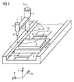
図1は生産機械の簡単な例、即ち純粋に模範的な中繰り盤の形態の工作機械を示す。 FIG. 1 shows a simple example of a production machine, ie a machine tool in the form of a purely exemplary lathe.
図1によれば、工作機械は本体1を有し、本体1は主軸2を担持し、主軸2は回動アーム3を支持している。回動アーム3は第1の電気的位置決め駆動部4を用いて回動軸線5の周りを回動可能である。従って第1の位置決め駆動部4は回転駆動部である。回動アーム3は、その半径方向外側に配置される端部に、回転駆動部7を備えた中繰り主軸6を担持している。従って、回動アーム3が回動可能であるため、中繰り主軸6は、半径rが中繰り主軸6と回動軸線5との間隔に相当する円Kに沿って走行可能である。
According to FIG. 1, the machine tool has a main body 1, which carries a main shaft 2, which supports a rotating arm 3. The rotation arm 3 can be rotated around the rotation axis 5 by using the first electrical
中繰り主軸6を用いて工作物8に中繰り穴を形成できる。この場合、中繰り穴の形成は中繰り主軸6を降下させることで行う。中繰り主軸6の降下は、第1の位置決め駆動部4又は簡単のため図1には示さない他の駆動部で行える。第1の位置決め駆動部4で中繰り主軸6の降下を行うなら、位置決め駆動部4は回転・昇降複合駆動部として構成する。
An intermediate hole can be formed in the workpiece 8 by using the intermediate spindle 6. In this case, the intermediate hole is formed by lowering the intermediate spindle 6. The lowering of the intermediate feed spindle 6 can be performed by the first
加工対象である工作物8は工作台9の上に固定されている。工作台9は第2の電気的位置決め駆動部10を用いて本体1に沿って走行可能である。
A workpiece 8 to be machined is fixed on a work table 9. The work table 9 can travel along the main body 1 using the second electrical
図2は第2の位置決め駆動部10の構成の詳細図である。
FIG. 2 is a detailed view of the configuration of the second
図2によれば、第2の位置決め駆動部10は固定子11と可動子12とを備える。可動子12は線形滑動体であり、固定子11に対し直線走行方向xに移動できる。固定子11は本体1と堅固に結合され、例えば本体1と一体に形成されている。可動子12は工作台9と堅固に結合されており、例えば工作台9と一体に形成されている。従って第2の位置決め駆動部10は線形駆動部であり、該線形駆動部により工作台9は本体1に対し直線走行方向xに沿って走行可能である。
According to FIG. 2, the second
可動子12は、第2の位置決め駆動部10の走行方向xに対し横方向、即ち支持方向yとzに、磁場により固定子11に対し非接触で支持されている。なお磁場は、可動子12の非接触支持と駆動とを行う強力な電磁石13により発生する。
The
可動子12が固定子11に対し非接触支持されているため、可動子12が固定子11に対し走行方向xばかりか、支持方向y、zにも変位することがあり得る。この際、支持方向yとzにおける純粋に直線的な変位だけでなく、これら方向x、y、zの内の1つ又は幾つかの方向の周りで、即ち回転方向α、β、γの周りで工作台9が回転可能である。
Since the
この種の変位を検知すべく、センサ装置14を設けている。センサ装置14は、例えば多数の個々のセンサ15と評価装置16とを備える。各センサ15は工作台9と本体1との間隔又は可動子12と固定子11との間隔を非接触で検出する。間隔の検出は、例えば超音波往復時間の測定や、誘導的測定法で行える。他の間隔検出方法も採用できる。
A sensor device 14 is provided to detect this type of displacement. The sensor device 14 includes, for example, a large number of
センサ15は、図2によれば、支持方向yにおいては両側に、そして支持方向zにおいては可動子12の下方に配置されている。センサ15により走行方向xでの可動子12の位置と、支持方向y、zでの可動子12の平均変位量とを検出可能とすべく、これらセンサ15は、走行方向xにおいて互いに間隔を置いて配置するばかりか、y軸線とz軸線の周りでの可動子12の傾動量β、γおよびx軸線の周りでの回動量αをも検出可能であるように、走行方向xにおいて互いに間隔を置いて配置するとよい。
According to FIG. 2, the
センサ15から提供された全ての信号を評価する際、評価装置16は、支持方向yとzにおける可動子12の直線的変位量ばかりか、走行方向xおよび支持方向y、zの周りでの可動子12の回転量をも検出する。精度に対する要求が少ないなら、支持方向yとzにおける直線的変位量のみ、又は回動量αと傾動量β、γのみを検出すれば足りる。
When evaluating all the signals provided from the
検知又は検出した可動子12の変位量は、図2の如く、制御装置17に送られる。制御装置17も同様に第2の位置決め駆動部10に付設されている。制御装置17は、該制御装置に送られた変位量を対応する可動子12の目標支持位置と比較する。なお目標支持位置は一定であってよいが、走行方向xにおける可動子12の位置、或いは工作機械の他の構成要素の位置に依存するか、外部から制御装置17に供給された位置の何れかであってもよい。また、走行方向xにおける可動子12の位置と工作機械の他の構成要素の位置との双方に依存する組み合わせ型の依存性も考えられる。
The detected or detected displacement of the
上記比較に基づき、制御装置17は位置決め磁石システム18のための調整信号を求める。位置決め磁石システム18も同様に第2の位置決め駆動部10に付設されたものである。位置決め磁石システム18は、好適には多数の電磁石19を有し、各電磁石19は個別に制御可能である。各センサ15に1つの電磁石19を付設するとよい。
Based on the comparison, the
制御装置17は、該制御装置で求めた調整信号を位置決め磁石システム18へ送る。位置決め磁石システム18は、この所定の調整信号に応じ、支持方向y、z、α、β、γにおける固定子11に対する可動子12の支持位置を非接触で追跡する。
The
図3は、第1の位置決め駆動部4の構成を更に詳細に示す。第1の位置決め駆動部4の構成は、基本的には第2の位置決め駆動部10の構成に対応している。唯一の主要な相違点は、可動子12が直線可動子ではなくて、回転子であることである。これに応じて、第1の位置決め駆動部4の走行方向も回転方向γ、即ち回動軸線5の周りでの回転方向であり、直線方向x、y、zの周りでの回転方向ではない。
FIG. 3 shows the configuration of the first
第1の位置決め駆動部4をこのように構成したので、支持方向yとzにおける可動子12の変位量を検出し、かつ回動軸線5の周りでの可動子12の傾動量α、βを検出するには、可動子12の軸線方向に互いに間隔を持って位置している該可動子12の両端部において、各々支持方向yとzにおける該可動子12の変位量を検出すれば足りる。この際、これら測定値の平均値は支持方向yとzにおける直線変位を生じさせ、対応するセンサ15の軸線方向の間隔と関連した差は、傾動αとβを生じさせる。
Since the first
図3の実施形態でも、個々のケースに応じ、可動子12の純粋に直線的な変位量のみ又は可動子12の純粋な傾動量のみを検出又は評価すれば足りる。しかし通常は、直線的支持方向y、zと回転方向α、βとの双方の検出と評価を優先させるべきである。
In the embodiment of FIG. 3 as well, it is sufficient to detect or evaluate only a pure linear displacement amount of the
図1に示す如く、第1の位置決め駆動部4は回転・昇降複合駆動部として構成し得る。この際、可動子12は回動軸線5の周りで回転可能であり、且つ回動軸線5に沿って、即ちz方向に移動可能である。これに対応し、この場合第1の位置決め駆動部4は2つの走行方向z、γを有し、これら両走行方向の内zは直線方向、γは回転方向である。
As shown in FIG. 1, the first
かかる駆動部でも、可動子12の変位量を検出し、可動子12の支持位置を追跡することで補正が行える。この場合、回動軸線5の方向z、或いはより一般的には回転・昇降複合駆動部4の軸線の方向に見て、多数のセンサ群と電磁石群を配置せねばならない。その際各センサ群は、図3との関連で前述したように構成できる。各電磁石群の電磁石19も図3に示すように配置する。なお、センサ群と電磁石群との軸線方向の間隔の大きさは、可動子12の位置又は変位量を、該可動子12の軸線方向位置と無関係に、即ちz方向の位置に関係なく、常に少なくとも2つのセンサ群で検知でき、且つ少なくとも2つの電磁石群により制御できるように選定するのが好ましい。何故なら、このようにすると、この場合にも、可動子12の直線変位量も傾動量も常に検知且つ補正可能だからである。
Even in such a drive unit, the displacement can be corrected by detecting the displacement amount of the
このように、本発明による電気機械を用いると、付属の位置決め駆動部4、10を非接触作動する磁場支持型駆動部4、10として構成したにも係らず、工作物8の高精度な位置決めが常に可能である。
As described above, when the electric machine according to the present invention is used, although the attached
4 電気的位置決め駆動部、5 回動軸線、10 電気的位置決め駆動部、11 固定子、12 可動子、14 センサ装置、17 制御装置、18 位置決め磁石システム、x、y、z 直線走行方向(支持方向)、α、β、γ 回転方向(支持方向) 4 electrical positioning drive unit, 5 rotation axis, 10 electrical positioning drive unit, 11 stator, 12 mover, 14 sensor device, 17 control device, 18 positioning magnet system, x, y, z linear travel direction (support Direction), α, β, γ Rotation direction (support direction)
Claims (7)
位置決め駆動部(4、10)にセンサ装置(14)が付設され、該センサ装置(14)により前記少なくとも1つの支持方向(y、z、α、β、γ、x、y、z、α、β)における可動子(12)の固定子(11)に対する変位量が非接触で検出され、
位置決め駆動部(4、10)に制御装置(17)が付設され、該制御装置(17)に、センサ装置(14)によって検出した、前記少なくとも1つの支持方向(y、z、α、β、γ、x、y、z、α、β)における可動子(12)の固定子(11)に対する変位量が供給され、
制御装置(17)により、前記少なくとも1つの支持方向(y、z、α、β、γ、x、y、z、α、β)における可動子(12)の固定子(11)に対する変位量と、前記少なくとも1つの支持方向(y、z、α、β、γ、x、y、z、α、β)における可動子(12)の固定子(11)に対する目標支持位置とに基づいて、位置決め磁石システム(18)に対する調整信号を求めて、該位置決め磁石システム(18)に出力され、更に
前記少なくとも1つの支持方向(y、z、α、β、γ、x、y、z、α、β)における可動子(12)の固定子(11)に対する支持位置が、位置決め磁石システム(18)により非接触に追跡される。 A machine comprising at least one electrical positioning drive (4, 10) and having the following characteristics: The positioning drive unit (4, 10) includes a stator (11) and a movable element (12) movable in at least one traveling direction (x, z, γ) with respect to the stator (11). The mover (12) is at least one support direction (y, z, α, β, γ, x, different from the at least one travel direction (x, z, γ) relative to the stator (11). y, z, α, β) are non-contact supported by a magnetic field,
A sensor device (14) is attached to the positioning drive unit (4, 10), and the at least one support direction (y, z, α, β, γ, x, y, z, α, The displacement of the mover (12) relative to the stator (11) in β) is detected in a non-contact manner,
A control device (17) is attached to the positioning drive unit (4, 10), and the control device (17) has the at least one support direction (y, z, α, β, detected by the sensor device (14)). The displacement of the mover (12) relative to the stator (11) in γ, x, y, z, α, β) is supplied,
The displacement of the mover (12) relative to the stator (11) in the at least one support direction (y, z, α, β, γ, x, y, z, α, β) by the control device (17); Positioning based on the target support position of the mover (12) relative to the stator (11) in the at least one support direction (y, z, α, β, γ, x, y, z, α, β) An adjustment signal for the magnet system (18) is determined and output to the positioning magnet system (18), and further the at least one support direction (y, z, α, β, γ, x, y, z, α, β). The support position of the mover (12) with respect to the stator (11) is tracked in a non-contact manner by the positioning magnet system (18).
Applications Claiming Priority (2)
| Application Number | Priority Date | Filing Date | Title |
|---|---|---|---|
| DE102004039190A DE102004039190A1 (en) | 2004-08-12 | 2004-08-12 | Machine, in particular production machine, machine tool and / or robot |
| PCT/EP2005/053839 WO2006018390A1 (en) | 2004-08-12 | 2005-08-04 | Machine, especially production machine, machine-tool and/or robot |
Publications (2)
| Publication Number | Publication Date |
|---|---|
| JP2008509495A true JP2008509495A (en) | 2008-03-27 |
| JP2008509495A5 JP2008509495A5 (en) | 2008-08-07 |
Family
ID=35483568
Family Applications (1)
| Application Number | Title | Priority Date | Filing Date |
|---|---|---|---|
| JP2007525288A Pending JP2008509495A (en) | 2004-08-12 | 2005-08-04 | Machine with electrical positioning drive |
Country Status (4)
| Country | Link |
|---|---|
| US (1) | US7622833B2 (en) |
| JP (1) | JP2008509495A (en) |
| DE (1) | DE102004039190A1 (en) |
| WO (1) | WO2006018390A1 (en) |
Cited By (1)
| Publication number | Priority date | Publication date | Assignee | Title |
|---|---|---|---|---|
| KR101299392B1 (en) * | 2011-08-29 | 2013-08-22 | 현대제철 주식회사 | Sample fixing unit steel sheet shear having the same |
Families Citing this family (4)
| Publication number | Priority date | Publication date | Assignee | Title |
|---|---|---|---|---|
| DE102006022193B4 (en) * | 2006-05-12 | 2009-08-27 | Rovema - Verpackungsmaschinen Gmbh | Vertical tubular bag machine with two linear motors |
| DE102006022192B4 (en) * | 2006-05-12 | 2009-08-27 | Rovema - Verpackungsmaschinen Gmbh | Device for welding a film web |
| EP3173887A1 (en) * | 2015-11-24 | 2017-05-31 | Siemens Aktiengesellschaft | Method for moving a linear actuator, linear actuator and production or packaging machine |
| EP3582043B1 (en) * | 2018-06-12 | 2022-07-20 | Siemens Aktiengesellschaft | Method, numerical control device and machine tool for machining a workpiece |
Citations (2)
| Publication number | Priority date | Publication date | Assignee | Title |
|---|---|---|---|---|
| JPH0917848A (en) * | 1995-06-30 | 1997-01-17 | Nikon Corp | Magnetic levitation type stage |
| JP2002292535A (en) * | 2001-03-29 | 2002-10-08 | Brother Ind Ltd | Spindle head of machine tool |
Family Cites Families (16)
| Publication number | Priority date | Publication date | Assignee | Title |
|---|---|---|---|---|
| DE3423403A1 (en) * | 1984-06-25 | 1986-01-02 | Redmer-Elektronik, 6200 Wiesbaden | Electric asynchronous motor |
| JPS6115560A (en) * | 1984-06-28 | 1986-01-23 | Toshiro Higuchi | Linear step motor |
| US4678971A (en) * | 1985-01-14 | 1987-07-07 | Hitachi, Ltd. | Linear motor and control method thereof |
| US4629262A (en) * | 1985-06-24 | 1986-12-16 | Sperry Corporation | Position sensor for magnetic suspension and pointing system |
| US4761876A (en) * | 1986-04-18 | 1988-08-09 | Dynamotion Corporation | High speed precision drilling system |
| EP0363165B1 (en) | 1988-10-04 | 1993-08-11 | Seiko Seiki Kabushiki Kaisha | Apparatus for use in a grinding or dressing machine |
| US6246204B1 (en) * | 1994-06-27 | 2001-06-12 | Nikon Corporation | Electromagnetic alignment and scanning apparatus |
| KR100387320B1 (en) * | 1994-07-14 | 2003-09-02 | 코닌클리케 필립스 일렉트로닉스 엔.브이. | An electric actuator having a cylindrical linear motion coil and an annular rotary motion coil, an actuator unit including the actuator and the measurement system, and a machine including the actuator or the actuator unit. |
| DE29505315U1 (en) * | 1995-03-29 | 1995-06-01 | Hydraulik Techniek Emmen Bv | Rotary lifting device |
| DE59914554D1 (en) * | 1998-12-21 | 2007-12-27 | Nti Ag | System with a linear motor and an electronics unit |
| DE10019951A1 (en) | 2000-04-20 | 2001-10-31 | Sig Positec Automation Gmbh | Device for winding a thread on a bobbin |
| DE10023973A1 (en) * | 2000-05-16 | 2001-11-29 | Daimler Chrysler Ag | Active spindle bearing |
| KR100462388B1 (en) * | 2002-01-12 | 2004-12-17 | 한국과학기술원 | A Stage Device Of X-Y Precision Drive Using VCM |
| US6693401B1 (en) * | 2002-08-19 | 2004-02-17 | Nutec Compnents, Inc. | Precision positioning tilt device |
| US20040089190A1 (en) * | 2002-11-08 | 2004-05-13 | Krishnan Ramu | Transportation system with linear switched reluctance actuator for propulsion and levitation |
| JP2005168154A (en) * | 2003-12-02 | 2005-06-23 | Chiba Seimitsu:Kk | Plane motor |
-
2004
- 2004-08-12 DE DE102004039190A patent/DE102004039190A1/en not_active Withdrawn
-
2005
- 2005-08-04 JP JP2007525288A patent/JP2008509495A/en active Pending
- 2005-08-04 US US11/573,603 patent/US7622833B2/en not_active Expired - Fee Related
- 2005-08-04 WO PCT/EP2005/053839 patent/WO2006018390A1/en active Application Filing
Patent Citations (2)
| Publication number | Priority date | Publication date | Assignee | Title |
|---|---|---|---|---|
| JPH0917848A (en) * | 1995-06-30 | 1997-01-17 | Nikon Corp | Magnetic levitation type stage |
| JP2002292535A (en) * | 2001-03-29 | 2002-10-08 | Brother Ind Ltd | Spindle head of machine tool |
Cited By (1)
| Publication number | Priority date | Publication date | Assignee | Title |
|---|---|---|---|---|
| KR101299392B1 (en) * | 2011-08-29 | 2013-08-22 | 현대제철 주식회사 | Sample fixing unit steel sheet shear having the same |
Also Published As
| Publication number | Publication date |
|---|---|
| WO2006018390A1 (en) | 2006-02-23 |
| DE102004039190A1 (en) | 2006-02-23 |
| US20070280809A1 (en) | 2007-12-06 |
| US7622833B2 (en) | 2009-11-24 |
Similar Documents
| Publication | Publication Date | Title |
|---|---|---|
| US7546787B2 (en) | Machine tool with improved concentricity | |
| US9024488B2 (en) | Robot drive with magnetic spindle bearings | |
| EP1114694B1 (en) | Machine tool | |
| KR101532060B1 (en) | Position feedback for self bearing motor | |
| EP2564152B1 (en) | Metrology apparatus | |
| US7343684B2 (en) | Robotic system with traction drive | |
| JP5471159B2 (en) | Machine tool controller | |
| WO2011077127A4 (en) | Machine tools and methods of operation thereof | |
| CN101357443A (en) | Machine tool having the function of correcting mounting error through contact detection | |
| US20080246358A1 (en) | Magnetic bearing spindle device for machine tool | |
| JP2008509495A (en) | Machine with electrical positioning drive | |
| JP2000079527A (en) | Driving device for moving platform in single plane | |
| JP2011255442A (en) | Reference position detecting device and reference position detecting method of machine tool | |
| JP6463926B2 (en) | Displacement compensation system for machine tools | |
| US6777834B2 (en) | Lift/swivel drive | |
| KR20130110655A (en) | System for compensating error of work machine spindle | |
| JP4838062B2 (en) | Machine Tools | |
| JPH04250307A (en) | Straightness measuring device | |
| JP5401858B2 (en) | Grinding machine and grinding method | |
| JPH0329535B2 (en) | ||
| JP2000176793A (en) | Machine tool | |
| CN110912373B (en) | Linear motor | |
| JP2015039012A (en) | Robot driving device having magnetic spindle bearing | |
| JP2023030668A (en) | Air spindle device | |
| JP2000167739A (en) | Machine tool |
Legal Events
| Date | Code | Title | Description |
|---|---|---|---|
| A521 | Written amendment |
Free format text: JAPANESE INTERMEDIATE CODE: A523 Effective date: 20080617 |
|
| A621 | Written request for application examination |
Free format text: JAPANESE INTERMEDIATE CODE: A621 Effective date: 20080617 |
|
| A131 | Notification of reasons for refusal |
Free format text: JAPANESE INTERMEDIATE CODE: A131 Effective date: 20101026 |
|
| A02 | Decision of refusal |
Free format text: JAPANESE INTERMEDIATE CODE: A02 Effective date: 20110405 |