EP3582043B1 - Method, numerical control device and machine tool for machining a workpiece - Google Patents
Method, numerical control device and machine tool for machining a workpiece Download PDFInfo
- Publication number
- EP3582043B1 EP3582043B1 EP18177170.0A EP18177170A EP3582043B1 EP 3582043 B1 EP3582043 B1 EP 3582043B1 EP 18177170 A EP18177170 A EP 18177170A EP 3582043 B1 EP3582043 B1 EP 3582043B1
- Authority
- EP
- European Patent Office
- Prior art keywords
- coordinate system
- axis
- rks
- tool
- rotation
- Prior art date
- Legal status (The legal status is an assumption and is not a legal conclusion. Google has not performed a legal analysis and makes no representation as to the accuracy of the status listed.)
- Active
Links
- 238000003754 machining Methods 0.000 title claims description 52
- 238000000034 method Methods 0.000 title claims description 38
- 230000000717 retained effect Effects 0.000 claims 1
- 230000009466 transformation Effects 0.000 description 15
- 230000008901 benefit Effects 0.000 description 6
- 238000006073 displacement reaction Methods 0.000 description 5
- 230000008859 change Effects 0.000 description 3
- 230000003068 static effect Effects 0.000 description 3
- 230000008878 coupling Effects 0.000 description 1
- 238000010168 coupling process Methods 0.000 description 1
- 238000005859 coupling reaction Methods 0.000 description 1
- 239000011159 matrix material Substances 0.000 description 1
- 230000008569 process Effects 0.000 description 1
- 230000001360 synchronised effect Effects 0.000 description 1
- 238000000844 transformation Methods 0.000 description 1
Images


Classifications
-
- G—PHYSICS
- G05—CONTROLLING; REGULATING
- G05B—CONTROL OR REGULATING SYSTEMS IN GENERAL; FUNCTIONAL ELEMENTS OF SUCH SYSTEMS; MONITORING OR TESTING ARRANGEMENTS FOR SUCH SYSTEMS OR ELEMENTS
- G05B19/00—Programme-control systems
- G05B19/02—Programme-control systems electric
- G05B19/18—Numerical control [NC], i.e. automatically operating machines, in particular machine tools, e.g. in a manufacturing environment, so as to execute positioning, movement or co-ordinated operations by means of programme data in numerical form
- G05B19/408—Numerical control [NC], i.e. automatically operating machines, in particular machine tools, e.g. in a manufacturing environment, so as to execute positioning, movement or co-ordinated operations by means of programme data in numerical form characterised by data handling or data format, e.g. reading, buffering or conversion of data
- G05B19/4086—Coordinate conversions; Other special calculations
-
- G—PHYSICS
- G05—CONTROLLING; REGULATING
- G05B—CONTROL OR REGULATING SYSTEMS IN GENERAL; FUNCTIONAL ELEMENTS OF SUCH SYSTEMS; MONITORING OR TESTING ARRANGEMENTS FOR SUCH SYSTEMS OR ELEMENTS
- G05B19/00—Programme-control systems
- G05B19/02—Programme-control systems electric
- G05B19/418—Total factory control, i.e. centrally controlling a plurality of machines, e.g. direct or distributed numerical control [DNC], flexible manufacturing systems [FMS], integrated manufacturing systems [IMS], computer integrated manufacturing [CIM]
- G05B19/41815—Total factory control, i.e. centrally controlling a plurality of machines, e.g. direct or distributed numerical control [DNC], flexible manufacturing systems [FMS], integrated manufacturing systems [IMS], computer integrated manufacturing [CIM] characterised by the cooperation between machine tools, manipulators and conveyor or other workpiece supply system, workcell
- G05B19/41825—Total factory control, i.e. centrally controlling a plurality of machines, e.g. direct or distributed numerical control [DNC], flexible manufacturing systems [FMS], integrated manufacturing systems [IMS], computer integrated manufacturing [CIM] characterised by the cooperation between machine tools, manipulators and conveyor or other workpiece supply system, workcell machine tools and manipulators only, machining centre
-
- B—PERFORMING OPERATIONS; TRANSPORTING
- B23—MACHINE TOOLS; METAL-WORKING NOT OTHERWISE PROVIDED FOR
- B23B—TURNING; BORING
- B23B1/00—Methods for turning or working essentially requiring the use of turning-machines; Use of auxiliary equipment in connection with such methods
-
- B—PERFORMING OPERATIONS; TRANSPORTING
- B23—MACHINE TOOLS; METAL-WORKING NOT OTHERWISE PROVIDED FOR
- B23B—TURNING; BORING
- B23B3/00—General-purpose turning-machines or devices, e.g. centre lathes with feed rod and lead screw; Sets of turning-machines
- B23B3/22—Turning-machines or devices with rotary tool heads
- B23B3/26—Turning-machines or devices with rotary tool heads the tools of which perform a radial movement; Rotary tool heads thereof
-
- B—PERFORMING OPERATIONS; TRANSPORTING
- B23—MACHINE TOOLS; METAL-WORKING NOT OTHERWISE PROVIDED FOR
- B23Q—DETAILS, COMPONENTS, OR ACCESSORIES FOR MACHINE TOOLS, e.g. ARRANGEMENTS FOR COPYING OR CONTROLLING; MACHINE TOOLS IN GENERAL CHARACTERISED BY THE CONSTRUCTION OF PARTICULAR DETAILS OR COMPONENTS; COMBINATIONS OR ASSOCIATIONS OF METAL-WORKING MACHINES, NOT DIRECTED TO A PARTICULAR RESULT
- B23Q15/00—Automatic control or regulation of feed movement, cutting velocity or position of tool or work
- B23Q15/007—Automatic control or regulation of feed movement, cutting velocity or position of tool or work while the tool acts upon the workpiece
- B23Q15/14—Control or regulation of the orientation of the tool with respect to the work
-
- G—PHYSICS
- G05—CONTROLLING; REGULATING
- G05B—CONTROL OR REGULATING SYSTEMS IN GENERAL; FUNCTIONAL ELEMENTS OF SUCH SYSTEMS; MONITORING OR TESTING ARRANGEMENTS FOR SUCH SYSTEMS OR ELEMENTS
- G05B19/00—Programme-control systems
- G05B19/02—Programme-control systems electric
- G05B19/18—Numerical control [NC], i.e. automatically operating machines, in particular machine tools, e.g. in a manufacturing environment, so as to execute positioning, movement or co-ordinated operations by means of programme data in numerical form
- G05B19/182—Numerical control [NC], i.e. automatically operating machines, in particular machine tools, e.g. in a manufacturing environment, so as to execute positioning, movement or co-ordinated operations by means of programme data in numerical form characterised by the machine tool function, e.g. thread cutting, cam making, tool direction control
-
- G—PHYSICS
- G05—CONTROLLING; REGULATING
- G05B—CONTROL OR REGULATING SYSTEMS IN GENERAL; FUNCTIONAL ELEMENTS OF SUCH SYSTEMS; MONITORING OR TESTING ARRANGEMENTS FOR SUCH SYSTEMS OR ELEMENTS
- G05B19/00—Programme-control systems
- G05B19/02—Programme-control systems electric
- G05B19/18—Numerical control [NC], i.e. automatically operating machines, in particular machine tools, e.g. in a manufacturing environment, so as to execute positioning, movement or co-ordinated operations by means of programme data in numerical form
- G05B19/4093—Numerical control [NC], i.e. automatically operating machines, in particular machine tools, e.g. in a manufacturing environment, so as to execute positioning, movement or co-ordinated operations by means of programme data in numerical form characterised by part programming, e.g. entry of geometrical information as taken from a technical drawing, combining this with machining and material information to obtain control information, named part programme, for the NC machine
-
- G—PHYSICS
- G05—CONTROLLING; REGULATING
- G05B—CONTROL OR REGULATING SYSTEMS IN GENERAL; FUNCTIONAL ELEMENTS OF SUCH SYSTEMS; MONITORING OR TESTING ARRANGEMENTS FOR SUCH SYSTEMS OR ELEMENTS
- G05B2219/00—Program-control systems
- G05B2219/30—Nc systems
- G05B2219/35—Nc in input of data, input till input file format
- G05B2219/35096—Kind of feature, rotational parts with machining features and relation
-
- G—PHYSICS
- G05—CONTROLLING; REGULATING
- G05B—CONTROL OR REGULATING SYSTEMS IN GENERAL; FUNCTIONAL ELEMENTS OF SUCH SYSTEMS; MONITORING OR TESTING ARRANGEMENTS FOR SUCH SYSTEMS OR ELEMENTS
- G05B2219/00—Program-control systems
- G05B2219/30—Nc systems
- G05B2219/49—Nc machine tool, till multiple
- G05B2219/49376—Select two machining types, milling or turning, complete machining with one tool
-
- Y—GENERAL TAGGING OF NEW TECHNOLOGICAL DEVELOPMENTS; GENERAL TAGGING OF CROSS-SECTIONAL TECHNOLOGIES SPANNING OVER SEVERAL SECTIONS OF THE IPC; TECHNICAL SUBJECTS COVERED BY FORMER USPC CROSS-REFERENCE ART COLLECTIONS [XRACs] AND DIGESTS
- Y02—TECHNOLOGIES OR APPLICATIONS FOR MITIGATION OR ADAPTATION AGAINST CLIMATE CHANGE
- Y02P—CLIMATE CHANGE MITIGATION TECHNOLOGIES IN THE PRODUCTION OR PROCESSING OF GOODS
- Y02P90/00—Enabling technologies with a potential contribution to greenhouse gas [GHG] emissions mitigation
- Y02P90/02—Total factory control, e.g. smart factories, flexible manufacturing systems [FMS] or integrated manufacturing systems [IMS]
Definitions
- the invention relates to a method and a numerical control device for controlling a relative movement between a tool and a workpiece for machining the workpiece using a machine tool. Furthermore, the invention relates to a machine tool for machining a workpiece using a tool, comprising at least three translational axes and at least one rotary axis and a tool spindle that can be rotated about a tool spindle axis for the relative movement of a tool connected to the tool spindle relative to a workpiece, which is mounted on a workpiece holder of the machine tool is attached.
- a method and a machine tool are known in which a tool spindle rotates around a tool spindle axis and synchronously therewith around an axis of rotation in such a way that a tool cutting edge performs a turning operation on a workpiece fixed firmly in the machine tool. While in classic turning the turning contour results from the movement of the tool relative to the workpiece rotating about a workpiece axis, in interpolation turning known from the cited patent application the tool moves with an oriented cutting edge about the axis of symmetry of the workpiece along the contour to be manufactured.
- Object of the present invention is therefore a method for controlling a machine tool, a numerical Specify control device and a machine tool with which the generation of tool paths for machining a workpiece is simplified.
- the object is solved by a numerical controller according to claim 14. Furthermore, the object is achieved by a machine tool according to claim 20.
- control is just common usage. In the strict control-technical sense, however, control processes are hidden behind it.
- a (stationary) machine coordinate system hereinafter referred to as MKS, is defined in relation to a machine base of the machine tool.
- a Cartesian coordinate system is advantageously selected for this purpose, which is aligned in such a way that the coordinate axes are aligned parallel to three or the three translatory axes (linear axes) of the machine tool. This reduces the computing effort involved in calculating the individual axis movements when traversing a specific tool path. In principle, however, any choice of the position of the coordinate origin and the orientation of the coordinate axes is possible.
- a rotational coordinate system hereinafter referred to as RKS
- RKS rotational coordinate system
- this can also be an arbitrary coordinate system.
- a Cartesian coordinate system is also advantageously selected for this.
- the coordinates of a point defined in the MKS can be specified in the RKS and vice versa by means of a corresponding coordinate transformation.
- path points or tool paths can be transferred or converted from one coordinate system to another.
- the use of coordinate transformations is known per se and customary in machine tools.
- the invention provides that the RKS is defined by specifying the coordinate origin with respect to the MKS and by specifying the orientation of at least one selected coordinate axis (for example the z′ axis) of the RKS in the MKS.
- the orientations of the other two coordinate axes can be defined as desired.
- three coordinate axes are preferably defined in such a way that they form a Cartesian coordinate system.
- an axis of rotation about which the RKS rotates in the MKS and an angular velocity at which the RKS rotates about the axis of rotation are specified.
- An axis that does not coincide with an axis of the MKS is preferably selected as the axis of rotation.
- the angular velocity is preferably defined in such a way that it correlates with a spindle speed of a tool spindle of the machine tool. In particular, the angular velocity corresponds to the spindle speed.
- both the MKS and the RKS are Cartesian coordinate systems.
- the procedure shown below could be used analogously for any coordinate system.
- Cartesian coordinate systems is common in connection with machine tools and makes it easier to calculate path points in different coordinate systems.
- At least the position and orientation of the axis of rotation, but in particular also the position and orientation of the RKS, are based on a workpiece machining axis.
- the workpiece machining axis is an axis of symmetry of an at least essentially rotationally symmetrical subarea of the workpiece (workpiece area) that is to be machined. Precisely this workpiece area is preferably to be machined by interpolation turning according to the invention.
- the workpiece machining axis results from the geometry data of the workpiece in connection with the clamping.
- the axis of rotation is aligned relative to the workpiece to lie on the workpiece machining axis of the workpiece.
- the RKS thus rotates around the workpiece machining axis.
- a further simplification can be achieved by orienting the selected coordinate axis (z') parallel to the axis of rotation.
- the origin of coordinates of the RKS is particularly advantageously defined in the MKS, for example by specifying a displacement vector, in particular for the "interpolation turning" application, in such a way that the origin of coordinates of the RKS lies on the workpiece machining axis.
- a displacement vector in particular for the "interpolation turning” application
- any point on the workpiece machining axis can serve as the coordinate origin of the RKS.
- the position and orientation of the selected coordinate axis are chosen so that they coincide with the workpiece machining axis. This means that turning cycles that have already been created for conventional lathes can be used for "interpolation turning" processing in the RKS, which define a contour in the x-z plane, for example.
- an orientation of another axis (x-axis) of the RKS can be changed depending on the type of rotation of the RKS (e.g. Euler or RPY).
- the tool spindle axis is advantageously aligned parallel to the selected axis (z'). This corresponds to the most common configuration on a conventional lathe.
- the tool spindle rotates around the tool spindle axis and the tool spindle axis rotates synchronously around the selected axis (z′) in relation to the MKS, so that when the tool spindle rotates around the tool spindle axis a rotation of the tool spindle axis around the selected axis (z') takes place.
- the cutting edge of the tool is always aligned towards the axis of symmetry of the part of the workpiece to be machined during a revolution around the part of the workpiece to be machined.
- the rotational speeds can also deviate from one another.
- the invention thus offers the advantage, among other things, that rotationally symmetrical partial areas of a workpiece that is not rotationally symmetrical per se can be machined in a relatively simple manner by interpolation turning.
- a desired contour of the workpiece no longer has to be broken down into a large number of tool paths using special cycles. Instead, simple turning cycles can be used for this purpose.
- skilful clamping of the workpiece in the machine tool can ensure that the workpiece machining axis lies in the x-y plane of the MCS. Then the RKS only needs to be pivoted about an axis of the WCS relative to it so that the selected axis (z′) coincides with the workpiece machining axis.
- the orientation of the selected axis By defining the orientation of the selected axis, the other two axes of the RKS are then also fixed in relation to the MKS.
- the definition of the coordinate origin and the orientation of the selected axis are sufficient to be able to derive the position and orientation of the RKS in the MKS and thus the coordinate transformation.
- the RKS can also have to be rotated in space about more than one axis relative to the MKS.
- the RKS then emerges from the MKS by specifying the displacement vector with respect to the coordinate origin and specifying the so-called Euler angle. With that can RKS coordinates are converted into MKS coordinates and vice versa.
- the orientation of the selected axis (z') depends on the workpiece machining axis. In principle, there are infinitely many possibilities for the orientation of the two other axes - even assuming a Cartesian RKS. In order to create a clear starting point for machining the workpiece, the orientation of a further axis of the RKS, for example the x′ axis, is specified. The orientation of the remaining axis, in the example the y′ axis, is thus also determined.
- the spindle position and orientation or the tool position and orientation are defined in the RKS, ie the initial position.
- the tool spindle axis is aligned parallel to the axis of rotation of the coordinate system.
- the tool in particular a tool cutting edge, is oriented towards the axis of rotation or in the opposite direction thereto.
- a contour—preferably rotationally symmetrical—of a workpiece or workpiece region that is to be created is specified in the RKS.
- Tool paths are then determined, in particular using turning algorithms that are used in the control or path generation of conventional lathes, which are used to generate the specified contour.
- the tool paths are defined with respect to the RKS and the relative movements between the tool and the workpiece are generated according to the tool paths defined in the RKS.
- the path points determined in the RKS are converted into path points or axis positions of the MKS by means of a corresponding coordinate transformation and approached accordingly.
- an advantage of introducing an RKS according to the invention is that the position and/or orientation of the tool spindle axis, the position and/or orientation of the tool, in particular a tool cutting edge, and the desired contour of the workpiece can now be defined in the RKS. This is done analogously to the definition of the corresponding sizes for a conventional lathe.
- the contour is preferably defined in the x′-z′ plane of the RKS. From this, the controller advantageously determines the ones to be produced tool paths required for the contour initially also in the RKS.
- the main difference to conventional interpolation turning is that the coordinate transformation for defining the RKS in relation to the MKS is not static, but dynamic. Synchronously with the rotation of the tool spindle, the RKS rotates with respect to the MKS about the selected axis (z'-axis) of the RKS. From the point of view of the RKS, the corresponding coupling of the machine axes means that the tool spindle and in particular the tool are stationary in relation to the partial area of the workpiece to be machined, whereas this partial area of the workpiece rotates around its axis of symmetry, the workpiece machining axis. From the programmer's point of view, this results in the same initial state as with turning using a conventional lathe. During the rotation of the tool spindle around the tool spindle axis and the rotation of the RKS in relation to the MKS, the machining paths of the tool (tool paths) defined in the RKS are traversed to produce the desired workpiece contour.
- the procedure according to the invention has the particular advantage that existing turning cycles programmed for conventional turning operations using conventional lathes can be used to determine tool paths.
- the creation of new, usually highly complex, special cycles for interpolation turning is therefore no longer necessary for many applications. This is a significant time and cost advantage.
- both the MKS and the RKS are preferably Cartesian coordinate systems.
- other coordinate systems can also be used as a basis in special cases for special applications.
- the kinematic chain Since orientations can only be changed by rotation, the kinematic chain must contain at least three rotary axes in order to be able to set any orientation in space.
- the total number of axes must be at least six, of which at least three are designed as rotary axes (rotary axes).
- the remaining three axes can (in any combination) be both rotary and linear axes.
- the number of constant offsets is arbitrary.
- the machine can also contain other (redundant) axes in the chain. The determination of the axis positions is then no longer unambiguous, or other criteria must be used for such constellations to determine the position of these axes.
- the tool When machining the perimeter of the part to be machined, the tool must be guided with constant orientation relative to the surface. This means that for one revolution around the circumference of the part, the tool must also rotate about an axis that is parallel to the machining axis of the workpiece at all times. Such a movement can be generated according to (3) by the rotations described with A 1 to A 3 being timed accordingly.
- the special case that is of particular interest is that the rotation described is carried out by only rotating a single rotary axis, while the other two rotary axes do not change their position during processing, i.e. they orient the third axis so that it is parallel to the processing axis is.
- This will typically be the third axis ( A 3 ), which must be designed as a (position-controlled) spindle and which carries the tool.
- FIG. 1 shows a preferred embodiment of the invention.
- a machine tool 1 shown in a schematic, greatly simplified representation comprises three translational axes L1, L2 and L3 (linear axes) by means of which a tool 2 can be moved in three linear spatial axes relative to a workpiece 3.
- the machine tool 1 includes a stationary machine base 4 to which a workpiece holder 5 is attached.
- a point on the stationary machine base 4 is chosen as the reference point (zero point) for a likewise stationary MKS with the coordinate axes x, y and z.
- the coordinate axes x, y and z of the MKS are advantageously selected such that the x-axis is aligned parallel to L1, the y-axis is parallel to L2 and the z-axis is parallel to L3.
- the machine tool 1 has a tool head that can be pivoted about a rotary axis B (rotary axis), by means of which the tool 2 can be pivoted about a B axis parallel to the y axis.
- the tool 2 is attached to a tool spindle 6 comprised by the tool head 10 and can be rotated about a tool spindle axis SA.
- the tool spindle 6 is also provided with a position-controlled drive, so that any angle can be set for the tool spindle 6 and a cutting edge 7 of the workpiece 2 can thereby be oriented with respect to the tool spindle axis SA.
- a numerical control 8 available for coordinated position control of the individual Axes of the machine tool 1 .
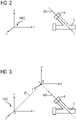
- Figure 2 again illustrates the MKS with the coordinate axes x, y and z as well as the non-rotationally symmetrical, stationary clamped workpiece 3 in the machine tool with a workpiece region 9 to be machined, which is rotationally symmetrical with respect to a workpiece machining axis WA.
- a Cartesian RKS with the coordinate axes x′, y′ and z′ is initially defined for the machining of the workpiece 3 to be carried out.
- a displacement vector is initially used for this purpose v determined for the origin of coordinates in such a way that the origin of coordinates 0' of the RKS lies on the workpiece machining axis WA of the workpiece 3.
- the workpiece machining axis WA is an axis of symmetry of a workpiece region 9 that is to be machined according to the invention.
- the z'-axis oriented so that it lies on the workpiece machining axis WA of the workpiece 3.
- the workpiece machining axis WA lies in the xz plane of the MKS due to a corresponding positioning and orientation of the workpiece 3 .
- the orientation of the z'-axis results from the MCS by a single pivoting movement of the z-axis about the y-axis. It is therefore sufficient to specify a single angle ⁇ by which the x′-axis and the z′-axis must be pivoted about the y′-axis in order to define the orientation of the RKS in the MKS. If the workpiece machining axis WA were not to lie in the xz plane of the MKS, at least one further pivoting movement would be required so that the z′ axis would come to lie on the workpiece machining axis WA.
- figure 5 1 shows the initial situation in which the position and orientation of the tool head 10 and in particular the tool cutting edge 7 are specified in the RKS.
- the spindle axis SA lies in the x'-z' plane and is oriented parallel to the z'-axis.
- the tool 2 is oriented in the opposite direction to the x' direction.
- a special feature of the coordinate transformation according to the invention is based on the fact that the RKS fixed as described now rotates continuously at a constant angular velocity ⁇ around the z′ axis.
- the angular velocity ⁇ ' with which the tool spindle 6 rotates about the tool spindle axis SA is therefore equal to the angular velocity ⁇ with which the RKS rotates about the z'-axis.
- the rotation of the tool spindle 6 is therefore synchronous with the rotation of the RKS.
- the cutting edge 7 thus always remains oriented parallel to the x′-axis, so that the cutting edge 7 always points to the z′-axis when the tool 2 rotates.
- This is in the Figures 6 and 7 illustrated, which shows the machining of the workpiece at two different points in time. An observer moving with the RKS thus sees a stationary tool with a constant orientation and a workpiece area 9 rotating about the z'-axis. However, this represents the typical initial situation for the machining type "turning" using a conventional lathe.
- the (rotationally symmetrical) contour of the workpiece region 9 to be machined is specified in the x′-z′ plane.
- the tool paths are then calculated in the controller 8--as in a conventional lathe.
- the controller 8 converts the tool paths calculated for the RKS, taking into account the coordinate transformation described above, into tool paths with respect to the MKS and the corresponding coordinated movements of the relevant machine axes L1 to L3 and B of the machine tool 1 .
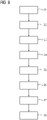
- figure 8 illustrates essential method steps in carrying out a method according to the invention.
- a first method step S1 an MKS that is stationary with respect to the machine tool used is defined.
- a workpiece machining axis for a workpiece region of the workpiece to be machined is defined for a workpiece to be machined that is clamped in the machine tool.
- the workpiece machining axis is an axis of symmetry of the workpiece area to be machined.
- the zero point of an RKS on the workpiece machining axis is defined in the MKS, for example by defining a displacement vector.
- the orientation of the RKS in relation to the MKS is defined in a method step S4. This generally requires three pivoting movements.
- a rotation around the y axis is sufficient so that the z' axis of the RKS coincides with the workpiece machining axis.
- the rotation of the tool spindle is started with the angular velocity ⁇ .
- a significant advantage achieved by the invention compared to conventional "interpolation turning” is based on the fact that existing turning cycles or existing tool paths can be used for turning and these only have to be specified in the RKS.
- the transformation then ensures that the machine itself performs relatively complex axis movements that lead to the desired machining, but that the specification of these axis movements in the RKS is relatively simple and largely corresponds to the specifications for conventional "turning".
- the basic principle explained by the exemplary embodiment can also be transferred analogously to more complex machining processes.
- the workpiece machining axis can be anywhere in the workspace of the machine tool.
- at least one further rotary axis of the machine tool may then be required, for example an A-axis for executing a pivoting movement of the tool about the x-axis or an axis parallel to the x-axis.
Description
Die Erfindung betrifft ein Verfahren sowie eine numerische Steuereinrichtung zur Steuerung einer Relativbewegung zwischen einem Werkzeug und einem Werkstück zur Bearbeitung des Werkstücks mittels einer Werkzeugmaschine. Ferner betrifft die Erfindung eine Werkzeugmaschine zur Bearbeitung eines Werkstücks mittels eines Werkzeugs, umfassend wenigstens drei translatorische Achsen und wenigstens eine rotatorische Achse sowie eine um eine Werkzeugspindelachse rotierbare Werkzeugspindel zur Relativbewegung eines mit der Werkzeugspindel verbundenen Werkzeuges relativ zu einem Werkstück, welches an einer Werkstückaufnahme der Werkzeugmaschine befestigt ist.The invention relates to a method and a numerical control device for controlling a relative movement between a tool and a workpiece for machining the workpiece using a machine tool. Furthermore, the invention relates to a machine tool for machining a workpiece using a tool, comprising at least three translational axes and at least one rotary axis and a tool spindle that can be rotated about a tool spindle axis for the relative movement of a tool connected to the tool spindle relative to a workpiece, which is mounted on a workpiece holder of the machine tool is attached.
Aus der
Nachteilig bei dem bekannten Verfahren zum Interpolationsdrehen ist, dass bei der Zerlegung einer Kontur in einer Bearbeitungsebene zur Festlegung der Werkzeugbahnen auf Spezialzyklen zurückgegriffen werden muss. Die Festlegung der Werkzeugbahnen ist daher komplex und mit hohem Aufwand verbunden.The disadvantage of the known method for interpolation turning is that special cycles have to be used to define the tool paths when dividing up a contour in a machining plane. Defining the tool paths is therefore complex and involves a great deal of effort.
Aufgabe der vorliegenden Erfindung ist es daher, ein Verfahren zur Steuerung einer Werkzeugmaschine, eine numerische Steuereinrichtung sowie eine Werkzeugmaschine anzugeben, mit denen die Erzeugung von Werkzeugbahnen zur Bearbeitung eines Werkstücks vereinfacht wird.Object of the present invention is therefore a method for controlling a machine tool, a numerical Specify control device and a machine tool with which the generation of tool paths for machining a workpiece is simplified.
Diese Aufgabe wird gelöst durch ein Verfahren nach Anspruch 1.This object is achieved by a method according to
Ferner wird die Aufgabe gelöst durch eine numerische Steuereinrichtung nach Anspruch 14. Weiterhin wird die Aufgabe gelöst durch eine Werkzeugmaschine nach Anspruch 20.Furthermore, the object is solved by a numerical controller according to claim 14. Furthermore, the object is achieved by a machine tool according to claim 20.
Selbstverständlich handelt es bei dem Begriff "Steuerung" lediglich um den üblichen Sprachgebrauch. Im streng regelungstechnischen Sinn verbergen sich dahinter jedoch Regelungsvorgänge.Of course, the term "control" is just common usage. In the strict control-technical sense, however, control processes are hidden behind it.
Wie üblich wird zunächst ein (ortsfestes) Maschinenkoordinatensystem, nachfolgend als MKS bezeichnet, in Bezug zu einer Maschinenbasis der Werkzeugmaschine festgelegt. Vorteilhaft wird hierfür ein kartesisches Koordinatensystem gewählt, welches so ausgerichtet wird, dass die Koordinatenachsen parallel zu drei bzw. den drei translatorischen Achsen (Linearachsen) der Werkzeugmaschine ausgerichtet sind. Dies reduziert den Rechenaufwand bei der Berechnung der einzelnen Achsbewegungen beim Abfahren einer bestimmten Werkzeugbahn. Prinzipiell sind jedoch eine beliebige Wahl der Lage des Koordinatenursprungs und der Orientierungen der Koordinatenachsen möglich.As usual, a (stationary) machine coordinate system, hereinafter referred to as MKS, is defined in relation to a machine base of the machine tool. A Cartesian coordinate system is advantageously selected for this purpose, which is aligned in such a way that the coordinate axes are aligned parallel to three or the three translatory axes (linear axes) of the machine tool. This reduces the computing effort involved in calculating the individual axis movements when traversing a specific tool path. In principle, however, any choice of the position of the coordinate origin and the orientation of the coordinate axes is possible.
Weiterhin wird bei der Erfindung ein Rotationskoordinatensystem, nachfolgend als RKS bezeichnet, in Relation zu dem Maschinenkoordinatensystem festgelegt. Auch hierbei kann es sich im Prinzip um ein beliebiges Koordinatensystem handeln. Vorteilhaft wird jedoch auch hierfür ein kartesisches Koordinatensystem gewählt. Durch eine entsprechende Koordinatentransformation können die Koordinaten eines in dem MKS festgelegten Punktes in dem RKS angegeben werden und umgekehrt. Entsprechend können Bahnpunkte bzw. Werkzeugbahnen von einem Koordinatensystem in ein anderes transferiert bzw. umgerechnet werden. Die Verwendung von Koordinatentransformationen ist bei Werkzeugmaschinen an sich bekannt und üblich.Furthermore, in the case of the invention, a rotational coordinate system, hereinafter referred to as RKS, is defined in relation to the machine coordinate system. In principle, this can also be an arbitrary coordinate system. However, a Cartesian coordinate system is also advantageously selected for this. The coordinates of a point defined in the MKS can be specified in the RKS and vice versa by means of a corresponding coordinate transformation. Correspondingly, path points or tool paths can be transferred or converted from one coordinate system to another. The use of coordinate transformations is known per se and customary in machine tools.
Allgemein sieht die Erfindung vor, dass das RKS durch Vorgabe des Koordinatenursprungs bezüglich des MKS sowie durch Vorgabe der Orientierung wenigstens einer ausgewählten Koordinatenachse (beispielsweise der z'-Achse) des RKS in dem MKS definiert wird. Die Orientierungen der beiden übrigen Koordinatenachsen sind beliebig festlegbar. Vorzugsweise werden bei dem RKS drei Koordinatenachsen so festgelegt, dass sie ein kartesisches Koordinatensystem bilden.In general, the invention provides that the RKS is defined by specifying the coordinate origin with respect to the MKS and by specifying the orientation of at least one selected coordinate axis (for example the z′ axis) of the RKS in the MKS. The orientations of the other two coordinate axes can be defined as desired. In the case of the RKS, three coordinate axes are preferably defined in such a way that they form a Cartesian coordinate system.
Weiterhin werden eine Rotationsachse, um die das RKS in dem MKS rotiert, sowie eine Winkelgeschwindigkeit, mit der das RKS um die Rotationsachse rotiert, festgelegt. Vorzugsweise wird als Rotationsachse eine Achse gewählt, die nicht mit einer Achse des MKS zusammenfällt. Vorzugsweise wird ferner die Winkelgeschwindigkeit so festgelegt, dass sie mit einer Spindeldrehzahl einer Werkzeugspindel der Werkzeugmaschine korreliert. Insbesondere entspricht die Winkelgeschwindigkeit der Spindeldrehzahl.Furthermore, an axis of rotation about which the RKS rotates in the MKS and an angular velocity at which the RKS rotates about the axis of rotation are specified. An axis that does not coincide with an axis of the MKS is preferably selected as the axis of rotation. Furthermore, the angular velocity is preferably defined in such a way that it correlates with a spindle speed of a tool spindle of the machine tool. In particular, the angular velocity corresponds to the spindle speed.
Durch diese Vorgehensweise ist es bei vielen Anwendungsfällen von Werkzeugmaschinen möglich, Werkstückkonturen oder Werkzeugbahnen, das heißt die Relativbewegungen zwischen dem Werkzeug und dem Werkstück, in verhältnismäßig einfacher Weise im RKS festzulegen bzw. zu beschreiben, woraus sich dann verhältnismäßig komplexe Bewegungen der Maschinenachsen bzw. verhältnismäßig komplexe Bewegungen des Werkzeuges relativ zu dem Werkstück im MKS ergeben.This procedure makes it possible in many applications of machine tools to define or describe workpiece contours or tool paths, i.e. the relative movements between the tool and the workpiece, in the RKS in a relatively simple manner, which then results in relatively complex movements of the machine axes or relatively complex movements of the tool relative to the workpiece in the MKS result.
Nachfolgend wird davon ausgegangen, dass es sich sowohl bei dem MKS als auch bei dem RKS um kartesische Koordinatensysteme handelt. Prinzipiell könnte die nachfolgend aufgezeigte Vorgehensweise jedoch analog für beliebige Koordinatensysteme angewandt werden. Die Verwendung kartesischer Koordinatensysteme ist im Zusammenhang mit Werkzeugmaschinen üblich und erleichtert die Berechnung von Bahnpunkten in unterschiedlichen Koordinatensystemen.In the following it is assumed that both the MKS and the RKS are Cartesian coordinate systems. In principle, however, the procedure shown below could be used analogously for any coordinate system. The use of Cartesian coordinate systems is common in connection with machine tools and makes it easier to calculate path points in different coordinate systems.
Bei der Erfindung richten sich zumindest die Lage und Orientierung der Rotationsachse, insbesondere aber auch die Lage und Orientierung des RKS, nach einer Werkstückbearbeitungsachse. Die Werkstückbearbeitungsachse ist eine Symmetrieachse eines wenigstens im Wesentlichen rotationssymmetrischen Teilbereichs des Werkstücks (Werkstückbereichs), der bearbeitet werden soll. Eben dieser Werkstückbereich soll vorzugsweise durch Interpolationsdrehen gemäß der Erfindung bearbeitet werden. Die Werkstückbearbeitungsachse ergibt sich aus den Geometriedaten des Werkstücks in Verbindung mit der Aufspannung.In the case of the invention, at least the position and orientation of the axis of rotation, but in particular also the position and orientation of the RKS, are based on a workpiece machining axis. The workpiece machining axis is an axis of symmetry of an at least essentially rotationally symmetrical subarea of the workpiece (workpiece area) that is to be machined. Precisely this workpiece area is preferably to be machined by interpolation turning according to the invention. The workpiece machining axis results from the geometry data of the workpiece in connection with the clamping.
Die Rotationsachse wird relativ zu dem Werkstück so ausgerichtet, dass sie auf der Werkstückbearbeitungsachse des Werkstücks liegt. Damit rotiert das RKS um die Werkstückbearbeitungsachse.The axis of rotation is aligned relative to the workpiece to lie on the workpiece machining axis of the workpiece. The RKS thus rotates around the workpiece machining axis.
Eine weitere Vereinfachung kann dadurch erreicht werden, dass die ausgewählte Koordinatenachse (z') parallel zu der Rotationsachse orientiert wird.A further simplification can be achieved by orienting the selected coordinate axis (z') parallel to the axis of rotation.
Besonders vorteilhaft, insbesondere für den Anwendungsfall "Interpolationsdrehen", wird der Koordinatenursprung des RKS in dem MKS so festgelegt, beispielsweise durch Angabe eines Verschiebungs-Vektors, dass der Koordinatenursprung des RKS auf der Werkstückbearbeitungsachse liegt. Im Prinzip kann jeder Punkt auf der Werkstückbearbeitungsachse als Koordinatenursprung des RKS dienen.The origin of coordinates of the RKS is particularly advantageously defined in the MKS, for example by specifying a displacement vector, in particular for the "interpolation turning" application, in such a way that the origin of coordinates of the RKS lies on the workpiece machining axis. In principle, any point on the workpiece machining axis can serve as the coordinate origin of the RKS.
Weiterhin werden Lage und Orientierung der ausgewählten Koordinatenachse (z'-Achse) so gewählt, dass sie mit der Werkstückbearbeitungsachse zusammenfällt. Dadurch kann für die Bearbeitung "Interpolationsdrehen" im RKS auf bereits für herkömmliche Drehmaschinen erstellte Drehzyklen zurückgegriffen werden, die beispielsweise eine Kontur in der x-z-Ebene festlegen.Furthermore, the position and orientation of the selected coordinate axis (z' axis) are chosen so that they coincide with the workpiece machining axis. This means that turning cycles that have already been created for conventional lathes can be used for "interpolation turning" processing in the RKS, which define a contour in the x-z plane, for example.
Nachdem eine ausgewählte Achse des RKS (z'-Achse) sowie der Nullpunkt des RKS festgelegt wurden kann eine Orientierung einer weiteren Achse (x-Achse) des RKS in Abhängigkeit der Art der Rotation des RKS (z. B. Euler oder RPY) um die ausgewählte Achse (z'-Achse) festgelegt werden. Vorteilhaft werden die Achsen des RKS in Bezug zu der Lage und Orientierung der Werkzeugspindelachse in ihrer Ausgangsposition derart festgelegt, dass die Werkzeugspindelachse in einer durch die ausgewählte Achse (z') und die weitere Achse (x') aufgespannten Ebene liegt. Wie beim Drehen üblich erfolgt dann die Zustellung des Werkzeugs in x'-Richtung bei y'=0.After a selected axis of the RKS (z'-axis) and the zero point of the RKS have been determined, an orientation of another axis (x-axis) of the RKS can be changed depending on the type of rotation of the RKS (e.g. Euler or RPY). the selected axis (z'-axis). The axes of the RKS are advantageously defined in relation to the location and orientation of the tool spindle axis in their starting position such that the tool spindle axis lies in a plane spanned by the selected axis (z') and the further axis (x'). As is usual with turning, the tool is then fed in the x' direction at y'=0.
Vorteilhaft wird die Werkzeugspindelachse parallel zur ausgewählten Achse (z') ausgerichtet. Dies entspricht der häufigsten Konstellation bei einer herkömmlichen Drehmaschine.The tool spindle axis is advantageously aligned parallel to the selected axis (z'). This corresponds to the most common configuration on a conventional lathe.
Vorteilhaft rotiert bei aktiver Transformation und eingeschalteter Werkzeugspindel die Werkzeugspindel um die Werkzeugspindelachse und synchron dazu die Werkzeugspindelachse um die ausgewählte Achse (z') in Bezug zu dem MKS, sodass bei einer Umdrehung der Werkzeugspindel um die Werkzeugspindelachse eine Umdrehung der Werkzeugspindelachse um die ausgewählte Achse (z') erfolgt. Dadurch ist die Werkzeugschneide während eines Umlaufs um den zu bearbeitenden Teil des Werkstücks stets hin zu der Symmetrieachse des zu bearbeitenden Teils des Werkstücks ausgerichtet. Insbesondere bei einem mehrschneidigen Werkzeug können die Rotationsgeschwindigkeiten jedoch auch voneinander abweichen.Advantageously, when the transformation is active and the tool spindle is switched on, the tool spindle rotates around the tool spindle axis and the tool spindle axis rotates synchronously around the selected axis (z′) in relation to the MKS, so that when the tool spindle rotates around the tool spindle axis a rotation of the tool spindle axis around the selected axis (z') takes place. As a result, the cutting edge of the tool is always aligned towards the axis of symmetry of the part of the workpiece to be machined during a revolution around the part of the workpiece to be machined. In the case of a multi-edged tool in particular, however, the rotational speeds can also deviate from one another.
Die Erfindung bietet somit unter anderem den Vorteil, dass damit rotationssymmetrische Teilbereiche eines an sich nicht rotationssymmetrischen Werkstücks in verhältnismäßig einfacher Weise durch Interpolationsdrehen bearbeitet werden können. Insbesondere muss eine gewünschte Kontur des Werkstücks nicht mehr durch spezielle Zyklen in eine Vielzahl von Werkzeugbahnen zerlegt werden. Vielmehr kann hierfür auf einfache Drehzyklen zurückgegriffen werden.The invention thus offers the advantage, among other things, that rotationally symmetrical partial areas of a workpiece that is not rotationally symmetrical per se can be machined in a relatively simple manner by interpolation turning. In particular, a desired contour of the workpiece no longer has to be broken down into a large number of tool paths using special cycles. Instead, simple turning cycles can be used for this purpose.
In vielen Anwendungsfällen kann durch eine geschickte Aufspannung des Werkstücks in der Werkzeugmaschine erreicht werden, dass die Werkstückbearbeitungsachse in der x-y-Ebene des MKS liegt. Dann muss das RKS lediglich um eine Achse des WKS gegenüber diesem geschwenkt werden, damit die ausgewählte Achse (z') auf mit der Werkstückbearbeitungsachse zusammenfällt. Durch die Festlegung der Orientierung der ausgewählten Achse liegen dann auch die beiden anderen Achsen des RKS bezüglich des MKS fest. Für diesen Spezialfall genügen also die Festlegung des Koordinatenursprungs sowie die Orientierung der ausgewählten Achse, um daraus die Lage und Orientierung des RKS in dem MKS und damit die Koordinatentransformation ableiten zu können.In many applications, skilful clamping of the workpiece in the machine tool can ensure that the workpiece machining axis lies in the x-y plane of the MCS. Then the RKS only needs to be pivoted about an axis of the WCS relative to it so that the selected axis (z′) coincides with the workpiece machining axis. By defining the orientation of the selected axis, the other two axes of the RKS are then also fixed in relation to the MKS. For this special case, the definition of the coordinate origin and the orientation of the selected axis are sufficient to be able to derive the position and orientation of the RKS in the MKS and thus the coordinate transformation.
Das RKS kann zum Erreichen einer gewünschten Lage und Orientierung der ausgewählten Achse (z') aber auch um mehr als eine Achse gegenüber dem MKS im Raum gedreht werden müssen. Beispielsweise geht dann das RKS durch Angabe des Verschiebungs-Vektors bezüglich des Koordinaten-Ursprungs sowie die Angabe der sog. Euler-Winkel aus dem MKS hervor. Damit können Koordinaten des RKS in Koordinaten des MKS umgerechnet werden und umgekehrt.However, to achieve a desired position and orientation of the selected axis (z′), the RKS can also have to be rotated in space about more than one axis relative to the MKS. For example, the RKS then emerges from the MKS by specifying the displacement vector with respect to the coordinate origin and specifying the so-called Euler angle. With that can RKS coordinates are converted into MKS coordinates and vice versa.
Die Orientierung der ausgewählten Achse (z') richtet sich nach der Werkstückbearbeitungsachse. Für die Orientierung der beiden übrigen Achsen gibt es - auch unter der Annahme eines kartesischen RKS - im Prinzip unendlich viele Möglichkeiten. Um eine klare Ausgangssituation für die Bearbeitung des Werkstücks zu schaffen, wird daher die Orientierung einer weiteren Achse des RKS, beispielsweise der x'-Achse, vorgegeben. Die Orientierung der verbleibenden Achse, im Beispiel der y'-Achse, ist damit auch bestimmt.The orientation of the selected axis (z') depends on the workpiece machining axis. In principle, there are infinitely many possibilities for the orientation of the two other axes - even assuming a Cartesian RKS. In order to create a clear starting point for machining the workpiece, the orientation of a further axis of the RKS, for example the x′ axis, is specified. The orientation of the remaining axis, in the example the y′ axis, is thus also determined.
Als Besonderheit wird im Zusammenhang mit der Erfindung jedoch keine statische, sondern eine dynamische Koordinatentransformation bestimmt. Es werden nämlich sowohl eine Rotationsachse, um die das RKS in dem MKS rotiert, vorzugsweise die z'-Achse, als auch eine Winkelgeschwindigkeit für die Rotation angegeben. Dies hat zur Folge, dass bei aktiver Transformation ein im RKS ortsfester Punkt aus Sicht des MKS mit eben dieser Winkelgeschwindigkeit um die Rotationsachse rotiert. Ebenso verhält es sich mit einer im RKS als ortsfest festgelegten Lage und Orientierung einer Werkzeugspindel bzw. eines damit verbundenen Werkzeuges. Auch diese rotieren bei eingeschalteter Transformation mit dieser Winkelgeschwindigkeit um die Rotationsachse.As a special feature, however, no static, but rather a dynamic coordinate transformation is determined in connection with the invention. Specifically, both an axis of rotation about which the RKS rotates in the MKS, preferably the z′ axis, and an angular velocity for the rotation are specified. As a result, when the transformation is active, a stationary point in the RKS rotates around the axis of rotation with precisely this angular velocity from the point of view of the MKS. The same applies to a position and orientation of a tool spindle or a tool connected to it that is defined as stationary in the RKS. When the transformation is switched on, these also rotate around the axis of rotation with this angular velocity.
Vorteilhaft wird vor dem Einschalten der Koordinatentransformation, also in dem noch statischen RKS, die Spindellage und -orientierung bzw. die Werkzeuglage und -orientierung im RKS festgelegt, also die Ausgangslage. Bei aktiver Transformation und bezüglich der Rotation des RKS synchroner Rotation der Werkzeugspindel wird so automatisch die richtige Interpolationsdrehbewegung der Werkzeugspindel erzeugt.Advantageously, before the coordinate transformation is switched on, ie in the still static RKS, the spindle position and orientation or the tool position and orientation are defined in the RKS, ie the initial position. When the transformation is active and the tool spindle rotates synchronously with respect to the rotation of the RKS, the correct interpolation rotary movement of the tool spindle is thus automatically generated.
In einer besonders vorteilhaften Ausführungsform ist die Werkzeugspindelachse parallel zur Rotationsachse des Koordinatensystems ausgerichtet.In a particularly advantageous embodiment, the tool spindle axis is aligned parallel to the axis of rotation of the coordinate system.
Bei einer weiterhin besonders vorteilhaften Ausführungsform ist das Werkzeug, insbesondere eine Werkzeugschneide, zu der Rotationsachse hin oder in dazu entgegengesetzter Richtung orientiert.In a further particularly advantageous embodiment, the tool, in particular a tool cutting edge, is oriented towards the axis of rotation or in the opposite direction thereto.
Unter den zuletzt gemachten Annahmen kann die Werkzeugbewegung im RKS wie bei einer einfach aufgebauten, 2-Achs Drehmaschine angegeben werden.Under the assumptions made last, the tool movement in the RKS can be specified as with a simply constructed, 2-axis lathe.
In der Regel wird im Zusammenhang mit der Erfindung eine zu erstellende - vorzugsweise rotationssymmetrische - Kontur eines Werkstücks bzw. Werkstückbereichs in dem RKS vorgegeben. Anschließend werden, insbesondere unter Verwendung von Drehalgorithmen, die bei der Steuerung bzw. Bahngenerierung herkömmlicher Drehmaschinen verwendet werden, Werkzeugbahnen ermittelt, die zur Erzeugung der vorgegebenen Kontur dienen.As a rule, in connection with the invention, a contour—preferably rotationally symmetrical—of a workpiece or workpiece region that is to be created is specified in the RKS. Tool paths are then determined, in particular using turning algorithms that are used in the control or path generation of conventional lathes, which are used to generate the specified contour.
Gemäß der Erfindung werden die Werkzeugbahnen bezüglich des RKS festgelegt und die Relativbewegungen zwischen dem Werkzeug und dem Werkstück gemäß der in dem RKS festgelegten Werkzeugbahnen erzeugt. Hierzu werden zur Bewegung der Maschinenachsen jeweils die in dem RKS bestimmten Bahnpunkte mittels einer entsprechenden Koordinatentransformation in Bahnpunkte bzw. Achspositionen des MKS gewandelt und entsprechend angefahren.According to the invention, the tool paths are defined with respect to the RKS and the relative movements between the tool and the workpiece are generated according to the tool paths defined in the RKS. For this purpose, in order to move the machine axes, the path points determined in the RKS are converted into path points or axis positions of the MKS by means of a corresponding coordinate transformation and approached accordingly.
Ein Vorteil der erfindungsgemäßen Einführung eines RKS besteht darin, dass nun die Lage und/oder Orientierung der Werkzeugspindelachse, die Lage und/oder Orientierung des Werkzeugs, insbesondere einer Werkzeugschneide, sowie die gewünschte Kontur des Werkstücks im RKS festgelegt werden können. Dies erfolgt analog zu der Festlegung der entsprechenden Größen bei einer herkömmlichen Drehmaschine. In Analogie zum Drehen mit einer herkömmlichen Drehmaschine erfolgt vorzugsweise die Festlegung der Kontur in der x'-z'-Ebene des RKS. Daraus ermittelt die Steuerung vorteilhaft die zum Herstellen der Kontur notwendigen Werkzeugbahnen zunächst ebenfalls im RKS.An advantage of introducing an RKS according to the invention is that the position and/or orientation of the tool spindle axis, the position and/or orientation of the tool, in particular a tool cutting edge, and the desired contour of the workpiece can now be defined in the RKS. This is done analogously to the definition of the corresponding sizes for a conventional lathe. In analogy to turning with a conventional lathe, the contour is preferably defined in the x′-z′ plane of the RKS. From this, the controller advantageously determines the ones to be produced tool paths required for the contour initially also in the RKS.
Der hauptsächliche Unterschied zum herkömmlichen Interpolationsdrehen liegt nun darin begründet, dass die Koordinatentransformation zur Festlegung des RKS in Bezug zu dem MKS nicht statisch, sondern dynamisch ist. Synchron zur Drehung der Werkzeugspindel rotiert das RKS in Bezug zu dem MKS um die ausgewählte Achse (z'-Achse) des RKS. Aus Sicht des RKS ergibt sich durch die entsprechende Kopplung der Maschinenachsen, dass die Werkzeugspindel und insbesondere das Werkzeug gegenüber dem zu bearbeitenden Teilbereich des Werkstücks ortsfest sind, wohingegen dieser Werkstückteilbereich um seine Symmetrieachse, die Werkstückbearbeitungsachse rotiert. Somit entsteht aus Sicht des Programmierers der gleiche Ausgangszustand wie bei der Drehbearbeitung mittels einer herkömmlichen Drehmaschine. Während der Rotation der Werkzeugspindel um die Werkzeugspindelachse und der Rotation des RKS in Bezug zu dem MKS werden nun zur Herstellung der gewünschten Werkstückkontur die in dem RKS festgelegten Bearbeitungsbahnen des Werkzeugs (Werkzeugbahnen) abgefahren.The main difference to conventional interpolation turning is that the coordinate transformation for defining the RKS in relation to the MKS is not static, but dynamic. Synchronously with the rotation of the tool spindle, the RKS rotates with respect to the MKS about the selected axis (z'-axis) of the RKS. From the point of view of the RKS, the corresponding coupling of the machine axes means that the tool spindle and in particular the tool are stationary in relation to the partial area of the workpiece to be machined, whereas this partial area of the workpiece rotates around its axis of symmetry, the workpiece machining axis. From the programmer's point of view, this results in the same initial state as with turning using a conventional lathe. During the rotation of the tool spindle around the tool spindle axis and the rotation of the RKS in relation to the MKS, the machining paths of the tool (tool paths) defined in the RKS are traversed to produce the desired workpiece contour.
Für den Benutzer ergibt sich bei der erfindungsgemäßen Vorgehensweise insbesondere der Vorteil, dass zur Bestimmung von Werkzeugbahnen bereits auf vorhandene, für herkömmliche Drehbearbeitungen mittels herkömmlicher Drehmaschinen programmierte Drehzyklen zurückgegriffen werden kann. Die Erstellung neuer, in der Regel hoch komplexen Spezialzyklen für das Interpolationsdrehen erübrigt sich dadurch für viele Anwendungsfälle. Dies ist ein wesentlicher Zeit- und Kostenvorteil.For the user, the procedure according to the invention has the particular advantage that existing turning cycles programmed for conventional turning operations using conventional lathes can be used to determine tool paths. The creation of new, usually highly complex, special cycles for interpolation turning is therefore no longer necessary for many applications. This is a significant time and cost advantage.
Wie bereits ausgeführt wurde, handelt es sich sowohl bei dem MKS als auch bei dem RKS vorzugsweise jeweils um ein kartesisches Koordinatensystem. Prinzipiell können in Sonderfällen für besondere Anwendungen auch andere Koordinatensysteme zugrunde gelegt werden. Die Festlegung des Koordinatenursprungs sowie die Ausrichtung der Achsen des Koordinatensystems in Relation zu dem bearbeitenden Teilbereich des Werkstücks erfolgen vorteilhaft analog zu der entsprechenden Auswahl bei der Drehbearbeitung mittels einer herkömmlichen Drehmaschine.As already stated, both the MKS and the RKS are preferably Cartesian coordinate systems. In principle, other coordinate systems can also be used as a basis in special cases for special applications. The determination of the origin of coordinates and the alignment of the axes of the coordinate system in In relation to the partial area of the workpiece to be machined, this is advantageously carried out analogously to the corresponding selection during turning by means of a conventional lathe.
Nachfolgend soll der mathematische Hintergrund zu der Erfindung näher erläutert werden. Es wird dazu davon ausgegangen, dass die Kinematik der Maschine durch eine Kette von Rundachsen, Linearachsen und konstanten Offsets beschrieben werden kann.The mathematical background to the invention will be explained in more detail below. It is assumed that the kinematics of the machine can be described by a chain of rotary axes, linear axes and constant offsets.
Im Zusammenhang mit der Erfindung ist es erforderlich, einen definierten Punkt am Werkstück mit einer definierten räumlichen Orientierung anzufahren. Um allgemein einen beliebigen Punkt mit einer beliebigen Orientierung anzufahren benötigt man wenigstens drei Freiheitsgrade der Orientierung und drei Freiheitsgrade der Translation.In connection with the invention, it is necessary to approach a defined point on the workpiece with a defined spatial orientation. In order to generally approach any point with any orientation, at least three degrees of freedom of orientation and three degrees of freedom of translation are required.
Da Orientierungen nur durch Drehungen veränderbar sind, muss die kinematische Kette mindestens drei rotatorische Achsen enthalten, um eine beliebige Orientierung im Raum einstellen zu können.Since orientations can only be changed by rotation, the kinematic chain must contain at least three rotary axes in order to be able to set any orientation in space.
Damit das Problem eindeutig lösbar ist, muss die Gesamtzahl der Achsen wenigstens sechs sein, von denen wenigstens drei als rotatorische Achsen (Rundachsen) ausgebildet sind. Die restlichen drei Achsen können (in beliebiger Kombination) sowohl Rund- als auch Linearachsen sein. Die Zahl der konstanten Offsets ist beliebig.So that the problem can be solved unequivocally, the total number of axes must be at least six, of which at least three are designed as rotary axes (rotary axes). The remaining three axes can (in any combination) be both rotary and linear axes. The number of constant offsets is arbitrary.
Hinweis: Die Maschine kann in der Kette auch weitere (redundante) Achsen enthalten. Die Bestimmung der Achspositionen ist dann nicht mehr eindeutig, bzw. es müssen für solche Konstellationen zur Positionsbestimmung dieser Achsen weitere Kriterien herangezogen werden.Note: The machine can also contain other (redundant) axes in the chain. The determination of the axis positions is then no longer unambiguous, or other criteria must be used for such constellations to determine the position of these axes.
Nachfolgend wird ein Beispiel für eine Kinematik mit drei Linear- und drei Rundachsen beschrieben:
Die Teile am Anfang und am Ende der kinematischen Kette und zwischen den rotatorischen Achsen werden als Abschnitte bezeichnet. D.h. es gibt genau vier Abschnitte. Jeder dieser Abschnitte kann Linearachsen enthalten (mit der Randbedingung, dass ihre Gesamtzahl drei ist).An example of kinematics with three linear and three rotary axes is described below:
The parts at the beginning and end of the kinematic chain and between the rotary axes are called sections. Ie there are exactly four sections. Each of these sections can contain linear axes (with the constraint that their total number is three).
Mit den Bezeichnungen
- rn
- Linearer Offset
- An
- Drehung (rotatorische Maschinenachse)
- u
- Werkzeugvektor
- F
- Drehung des Werkstückkoordinatensystems gegenüber dem MKS
- f
- Nullpunktverschiebung im gedrehten Werkstückkoordinatensystem
- S
- Drehung um die Bearbeitungsachse des Werkstücks
- p
- Position des Bearbeitungspunktes in Werkstückkoordinaten
- rn
- linear offset
- On
- Rotation (rotary machine axis)
- and
- tool vector
- f
- Rotation of the workpiece coordinate system in relation to the MCS
- f
- Work offset in the rotated workpiece coordinate system
- S
- Rotation around the machining axis of the workpiece
- p
- Position of the processing point in workpiece coordinates
Der lineare Offset ![]()
- Cn
- konstanter Offset
- kn
- Zahl der Linearachsen im Abschnitt n
- en1
- Einheitsvektor der i-ten Linearachsen im Abschnitt n
- xni
- Position der i-ten Linearachse im Abschnitt n
- cn
- constant offset
- kn
- Number of linear axes in section n
- en1
- Unit vector of the i-th linear axes in section n
- xni
- Position of the i-th linear axis in section n
Für die Bestimmung der Drehwinkel der Drehungen A n (d.h. der Orientierung) können in der obenstehenden Gleichung unter der Voraussetzung, dass ![]()
![]()
Bei bekannten Drehungen können die Positionen der drei Linearachsen dann als Lösung eines (linearen) Gleichungssystems bestimmt werden.With known rotations, the positions of the three linear axes can then be determined as the solution of a (linear) system of equations.
Bei der Bearbeitung am Umfang des zu fertigenden Teils muss das Werkzeug relativ zur Oberfläche mit konstanter Orientierung geführt werden. Das bedeutet, dass sich das Werkzeug bei einer Umdrehung am Umfang des Teils ebenfalls um eine Achse drehen muss, die zu jedem Zeitpunkt parallel zur Bearbeitungsachse des Werkstücks ist. Eine solche Bewegung kann nach (3) erzeugt werden, indem die mit A 1 bis A 3 beschriebenen Drehungen zeitlich entsprechend gesteuert werden.When machining the perimeter of the part to be machined, the tool must be guided with constant orientation relative to the surface. This means that for one revolution around the circumference of the part, the tool must also rotate about an axis that is parallel to the machining axis of the workpiece at all times. Such a movement can be generated according to (3) by the rotations described with A 1 to A 3 being timed accordingly.
Technologisch ist aber der Spezialfall von besonderem Interesse, dass die beschriebene Drehung ausgeführt wird, indem sich nur eine einzige Rundachse dreht, während die anderen beiden Rundachsen ihre Position während der Bearbeitung nicht verändern, d.h. sie orientieren die dritte Achse so, dass sie parallel zu Bearbeitungsachse ist. Typischerweise wird das die dritte Achse (A 3 ) sein, die als (lageregelte) Spindel ausgeführt sein muss und die das Werkzeug trägt.From a technological point of view, however, the special case that is of particular interest is that the rotation described is carried out by only rotating a single rotary axis, while the other two rotary axes do not change their position during processing, i.e. they orient the third axis so that it is parallel to the processing axis is. This will typically be the third axis ( A 3 ), which must be designed as a (position-controlled) spindle and which carries the tool.
Aus Gleichung (3) folgt dann für diesen Spezialfall: ![]()
![]()
Diese Vereinfachung ist nur möglich, wenn das Werkzeug relativ zum Werkstück durch geeignete Wahl von ϕ 0 korrekt orientiert werden kann, also wenn Bearbeitungsachse und Drehachse parallel sind.This simplification is only possible if the tool can be correctly oriented relative to the workpiece by a suitable choice of ϕ 0 , i.e. if the machining axis and the axis of rotation are parallel.
Die Erfindung wird nachfolgend anhand eines Ausführungsbeispiels näher erläutert. Es zeigen:
-
Figur 1 -
Figuren 2 bis 7 -
Figur 8
-
figure 1 a schematic representation of a machine tool suitable for carrying out the invention, -
Figures 2 to 7 Measures for carrying out the method according to the invention, -
figure 8 essential process steps in the implementation of a method according to the invention.
Nachfolgend wird anhand der
Gemäß der Erfindung wird für die auszuführende Bearbeitung des Werkstücks 3 zunächst ein kartesisches RKS mit den Koordinatenachsen x', y' und z' festgelegt. Wie aus
Weiterhin wird - wie aus
Unter der Maßgabe, dass auch die x'-Achse in der x-z-Ebene liegen soll, sind damit auch die Orientierungen der x'-Achse sowie der y'-Achse und damit das gesamte RKS in Bezug auf das MKS eindeutig bestimmt.With the proviso that the x′-axis should also lie in the x-z plane, the orientations of the x′-axis and the y′-axis and thus the entire RKS in relation to the MKS are also clearly determined.
Bei der erfindungsgemäßen Vorgehensweise werden die Werkzeugpfade zur Bearbeitung des Werkstücks 3 nicht in dem MKS sondern in dem RKS vorgegeben.
Eine Besonderheit der erfindungsgemäßen Koordinatentransformation liegt nun darin begründet, dass das wie beschrieben festgelegte RKS nun kontinuierlich mit konstanter Winkelgeschwindigkeit ω um die z'-Achse rotiert. Dies führt dazu, dass eine im RKS vorgegebene, konstante Position und Orientierung des Werkzeuges 2 aus Sicht des MKS zu einer Kreisbewegung des Werkzeuges 2 mit der Winkelgeschwindigkeit ω um die z'-Achse führt und sich die Orientierung der Schneide 7 bei dieser Bewegung ebenfalls mit der Winkelgeschwindigkeit ω ändert. Die Winkelgeschwindigkeit ω', mit der die Werkzeugspindel 6 um die Werkzeugspindelachse SA rotiert, ist somit gleich der Winkelgeschwindigkeit ω, mit der das RKS um die z'-Achse rotiert. Die Rotation der Werkzeugspindel 6 ist also synchron mit der Rotation des RKS. Im Ausführungsbeispiel bleibt die Schneide 7 damit stets parallel zu der x'-Achse orientiert, so dass die Schneide 7 bei der Rotation des Werkzeuges 2 stets zur z'-Achse weist. Dies ist in den
Ausgehend von dieser Ausgangssituation wird die (rotationssymmetrische) Kontur des zu bearbeitenden Werkstückbereiches 9 in der x'-z'-Ebene vorgegeben. Aus der vorgegebenen Kontur werden anschließend in der Steuerung 8 die Werkzeugbahnen - wie bei einer herkömmlichen Drehmaschine - berechnet. Die Steuerung 8 setzt die für das RKS berechneten Werkzeugbahnen unter Berücksichtigung der oben beschriebenen Koordinatentransformation in Werkzeugbahnen bezüglich des MKS und die entsprechenden koordinierten Bewegungen der betreffenden Maschinen-Achsen L1 bis L3 und B der Werkzeugmaschine 1 um.Based on this initial situation, the (rotationally symmetrical) contour of the workpiece region 9 to be machined is specified in the x′-z′ plane. From the given contour, the tool paths are then calculated in the
Ein durch die Erfindung erzielter, wesentlicher Vorteil gegenüber dem herkömmlichen "Interpolationsdrehen" liegt darin begründet, dass auf vorhandene Drehzyklen bzw. vorhandene Werkzeugbahnen zur Drehbearbeitung zurückgegriffen werden kann und diese lediglich in dem RKS vorgegeben werden müssen. Die Transformation sorgt dann dafür, dass die Maschine an sich relativ komplexe Achsbewegungen ausführt, die zu der gewünschten Bearbeitung führen, die Vorgabe dieser Achsbewegungen im RKS aber verhältnismäßig einfach ist und weitgehend den Vorgaben beim herkömmlichen "Drehen" entspricht.A significant advantage achieved by the invention compared to conventional "interpolation turning" is based on the fact that existing turning cycles or existing tool paths can be used for turning and these only have to be specified in the RKS. The transformation then ensures that the machine itself performs relatively complex axis movements that lead to the desired machining, but that the specification of these axis movements in the RKS is relatively simple and largely corresponds to the specifications for conventional "turning".
Das durch das Ausführungsbeispiel erläuterte Grundprinzip kann analog auch auf komplexere Bearbeitungsvorgänge übertragen werden. Insbesondere ist es nicht zwingend erforderlich, dass die Werkstückbearbeitungsachse in der x-z-Ebene des MKS liegt. Im Prinzip kann die Werkstückbearbeitungsachse beliebig im Arbeitsraum der Werkzeugmaschine liegen. Allerdings ist dann gegebenenfalls wenigstens eine weitere Rundachse der Werkzeugmaschine erforderlich, beispielsweise eine A-Achse zum Ausführen einer Schwenkbewegung des Werkzeuges um die x-Achse bzw. eine zur x-Achse parallele Achse.The basic principle explained by the exemplary embodiment can also be transferred analogously to more complex machining processes. In particular, it is not absolutely necessary for the workpiece machining axis to lie in the x-z plane of the MCS. In principle, the workpiece machining axis can be anywhere in the workspace of the machine tool. However, at least one further rotary axis of the machine tool may then be required, for example an A-axis for executing a pivoting movement of the tool about the x-axis or an axis parallel to the x-axis.
Bezüglich der Koordinatentransformation wäre allgemein eine Verschiebung und Orientierung des RKS gegenüber dem MKS im dreidimensionalen Raum erforderlich, was im Vergleich zu dem Ausführungsbeispiel zu mehr Rechenaufwand in der Steuerung und komplexeren Maschinenbewegungen führt. An den Vorteilen für den Benutzer einer entsprechend eingerichteten Werkzeugmaschine ändert dies jedoch nichts.With regard to the coordinate transformation, a displacement and orientation of the RKS relative to the MKS in three-dimensional space would generally be required, which in comparison to the exemplary embodiment leads to more computing effort in the control and more complex machine movements. However, this does not change the advantages for the user of a correspondingly set up machine tool.
Claims (20)
- Method for controlling a relative movement between a tool (2) and a workpiece (3) for machining the workpiece (3) using a machine tool (1),- wherein a machine coordinate system (MKS) is defined in relation to a machine base (4) of the machine tool (1),- wherein a rotation coordinate system (RKS) is defined in relation to the machine coordinate system (MKS) by:- defining the coordinate point of origin of the rotation coordinate system (RKS) in the machine coordinate system (MKS),- defining the orientation of at least one selected coordinate axis (z') of the rotation coordinate system (RKS) in the machine coordinate system (MKS),- defining an axis of rotation (z') around which the rotation coordinate system (RKS) rotates in the machine coordinate system (MKS),- defining an angular velocity (ω) with which the rotation coordinate system (RKS) rotates around the axis of rotation (z'),- wherein at least one tool path is defined in the rotation coordinate system (RKS),- wherein the relative movement is controlled according to the tool path defined in the rotation coordinate system (RKS),- wherein the axis of rotation (z') is aligned relative to the workpiece such that the axis of rotation lies on a workpiece machining axis (WA) of a workpiece section (9) of the workpiece (3) to be machined by the tool (2),- characterised in that
the workpiece machining axis (WA) is an axis of symmetry of a subsection of the workpiece (3) to be machined, which is at least essentially rotationally symmetrical. - Method according to claim 1, wherein the selected coordinate axis (z') is oriented parallel to the axis of rotation (z').
- Method according to claim 1 or 2, wherein the position and orientation of the rotation coordinate system (RKS) is defined in the machine coordinate system (MKS) such that the selected coordinate axis (z') lies on the axis of rotation (z').
- Method according to one of claims 1 to 3, wherein the machine coordinate system (MKS) and/or the rotation coordinate system (RKS) are realised as Cartesian coordinate systems.
- Method according to one of claims 1 to 4, wherein the tool (2) is moved relative to the workpiece (3) by means of at least three translational axes (L1, L2, L3) and at least one rotational axis (B).
- Method according to one of claims 1 to 5, wherein the tool (2) is fixed in a tool spindle (6) and can be rotated around a tool spindle axis (SA).
- Method according to claim 6, wherein a position and orientation of the tool spindle axis (SA) is defined in the rotation coordinate system (RKS).
- Method as claimed in claim 7, wherein the tool spindle (6) is aligned relative to the rotation coordinate system (RKS) such that the tool spindle axis (SA) lies in a plane defined by two coordinate axes (x', z') of the rotation coordinate system (RKS).
- Method according to claim 7 or 8, wherein the tool spindle (6) is aligned parallel to the selected coordinate axis (z') of the rotation coordinate system (RKS).
- Method according to one of claims 1 to 9, wherein an orientation of at least one cutting edge (7) of the tool (2) is defined in the rotation coordinate system (RKS) and wherein the tool path includes the orientation of the cutting edge (7) .
- Method according to claim 10, wherein the orientation of the cutting edge (7) in the rotation coordinate system (RKS) is retained during the machining of the workpiece (3).
- Method according to one of claims 1 to 11, wherein the tool path is calculated on the basis of a stipulated contour of the workpiece section (9).
- Method according to one of claims 1 to 12, wherein the tool path is defined by a turning cycle programmed for conventional turning.
- Numerical control device (8) configured for controlling a relative movement between a tool (2) and a workpiece (3) for machining the workpiece (3) using a machine tool (1),- wherein a machine coordinate system (MKS) can be defined in relation to a machine base (4) of the machine tool (1),- wherein a rotation coordinate system (RKS) can be defined in relation to the machine coordinate system (MKS) by:- defining the coordinate point of origin of the rotation coordinate system (RKS) in the machine coordinate system (MKS),- defining the orientation of at least one selected coordinate axis (z') of the rotation coordinate system (RKS) in the machine coordinate system (MKS),- defining an axis of rotation (z') around which the rotation coordinate system (RKS) rotates in the machine coordinate system (MKS),- defining an angular velocity (ω) with which the rotation coordinate system (RKS) rotates around the axis of rotation (z'),- wherein at least one tool path can be defined in the rotation coordinate system (RKS),- wherein the relative movement can be controlled according to the tool path defined in the rotation coordinate system (RKS),- wherein the axis of rotation (z') can be aligned relative to the workpiece (3) such that the axis of rotation lies on a workpiece machining axis (WA) of a workpiece section (9) of the workpiece to be machined by the tool (2),- characterised in that
the workpiece machining axis (WA) is an axis of symmetry of a subsection of the workpiece (3) to be machined, which is at least essentially rotationally symmetrical. - Numerical control device (8) according to claim 14, wherein a selected coordinate axis (z') of the rotation coordinate system (RKS) can be defined as the axis of rotation (z').
- Numerical control device (8) according to claim 14 or 15, wherein the WKS and/or the rotation coordinate system (RKS) can be realised as Cartesian coordinate systems.
- Numerical control device (8) according to one of claims 14 to 16, wherein an orientation of at least one cutting edge (7) of the tool (2) can be defined in the rotation coordinate system (RKS) and wherein the tool path includes the orientation of the cutting edge (2).
- Numerical control device (8) according to claim 17, wherein the orientation of the cutting edge (2) in the rotation coordinate system (RKS) is constant during the machining of the workpiece (3).
- Numerical control device (8) according to one of claims 14 to 18, wherein the tool spindle (6) can be aligned relative to the rotation coordinate system (RKS) such that the tool spindle axis (SA) lies in a plane defined by two coordinate axes (x', z') of the rotation coordinate system (RKS).
- Machine tool (1) for machining a workpiece (3) using a tool (2), comprising:- at least three translational axes (L1, L2, L3) and at least one rotational axis (B), as well as a tool spindle (6) that can be rotated around a tool spindle axis (SA) for the relative movement of a tool (2) connected to the tool spindle (6) relative to a workpiece (3) affixed to a workpiece holder (5) of the machine tool (1),- means of defining a machine coordinate system (MKS) in relation to a machine base (4) of the machine tool (1),- means of defining a rotation coordinate system (RKS) in relation to the machine coordinate system (MKS),- wherein the coordinate point of origin of the rotation coordinate system (RKS) can be defined in the machine coordinate system (MKS),- wherein the orientation of at least one selected coordinate axis (z') of the rotation coordinate system (RKS) can be defined in the machine coordinate system (MKS),- wherein an axis of rotation (z') around which the rotation coordinate system (RKS) rotates can be defined in the machine coordinate system (MKS),- wherein an angular velocity (ω) with which the rotation coordinate system (RKS) rotates around the axis of rotation (z') can be defined in the machine coordinate system,- means of defining at least one tool path in the rotation coordinate system (RKS),- a numerical control device (8) according to one of claims 14 to 19 for controlling the relative movement between the tool (2) and the workpiece (3) according to the tool path defined in the RKS.
Priority Applications (3)
| Application Number | Priority Date | Filing Date | Title |
|---|---|---|---|
| EP18177170.0A EP3582043B1 (en) | 2018-06-12 | 2018-06-12 | Method, numerical control device and machine tool for machining a workpiece |
| US16/437,868 US11036207B2 (en) | 2018-06-12 | 2019-06-11 | Method, numerical control device and machine tool for machining a workpiece |
| CN201910505274.9A CN110586960B (en) | 2018-06-12 | 2019-06-12 | Method for machining a workpiece, numerical control device and machine tool |
Applications Claiming Priority (1)
| Application Number | Priority Date | Filing Date | Title |
|---|---|---|---|
| EP18177170.0A EP3582043B1 (en) | 2018-06-12 | 2018-06-12 | Method, numerical control device and machine tool for machining a workpiece |
Publications (2)
| Publication Number | Publication Date |
|---|---|
| EP3582043A1 EP3582043A1 (en) | 2019-12-18 |
| EP3582043B1 true EP3582043B1 (en) | 2022-07-20 |
Family
ID=62630951
Family Applications (1)
| Application Number | Title | Priority Date | Filing Date |
|---|---|---|---|
| EP18177170.0A Active EP3582043B1 (en) | 2018-06-12 | 2018-06-12 | Method, numerical control device and machine tool for machining a workpiece |
Country Status (3)
| Country | Link |
|---|---|
| US (1) | US11036207B2 (en) |
| EP (1) | EP3582043B1 (en) |
| CN (1) | CN110586960B (en) |
Families Citing this family (2)
| Publication number | Priority date | Publication date | Assignee | Title |
|---|---|---|---|---|
| EP3958075A1 (en) | 2020-08-17 | 2022-02-23 | Siemens Aktiengesellschaft | Interpolation turning with variable angular velocity |
| CN112363453B (en) * | 2020-10-19 | 2022-10-18 | 上海航天设备制造总厂有限公司 | Method for machining large non-orthogonal-angle special-shaped deep cavity part by using 90-degree side milling head |
Family Cites Families (17)
| Publication number | Priority date | Publication date | Assignee | Title |
|---|---|---|---|---|
| AU664372B2 (en) * | 1991-06-04 | 1995-11-16 | Anca Pty Ltd | Improvements in or relating to computer numerically controlled machines |
| TW301619B (en) | 1994-10-07 | 1997-04-01 | Toshiba Machine Co Ltd | |
| DE19841716A1 (en) * | 1998-09-11 | 2000-03-16 | Siemens Ag | Movement guidance control for industrial processing machine |
| DE19848642A1 (en) | 1998-10-22 | 2000-04-27 | Heidenhain Gmbh Dr Johannes | Temperature-dependent variation compensation method for machine tool or robot geometry corrects user input commands before conversion from input coordinate system into machine coordinate system |
| US7283889B2 (en) * | 2003-02-19 | 2007-10-16 | Fanuc Ltd | Numerical control device, and numerical control method |
| US7241981B2 (en) * | 2004-03-05 | 2007-07-10 | Lap Laser Llc | Systems and methods for displaying images and processing work pieces |
| DE102004039190A1 (en) * | 2004-08-12 | 2006-02-23 | Siemens Ag | Machine, in particular production machine, machine tool and / or robot |
| GB0525306D0 (en) * | 2005-12-13 | 2006-01-18 | Renishaw Plc | Method of machine tool calibration |
| US8024068B2 (en) * | 2006-08-04 | 2011-09-20 | Hurco Companies, Inc. | Machine tool control system |
| JP2008126391A (en) * | 2006-11-24 | 2008-06-05 | Towa Corp | Method and device for machining structure |
| MX2010006508A (en) * | 2007-12-14 | 2010-08-18 | Micrus Endovascular Corp | Multistrand coil for interventional therapy. |
| JP2011011295A (en) | 2009-07-02 | 2011-01-20 | Nachi Fujikoshi Corp | Fine recessed part working method and fine recessed part working machine |
| JP5289601B1 (en) * | 2012-03-19 | 2013-09-11 | ファナック株式会社 | Cutting distance calculator for multi-axis machines |
| KR101632486B1 (en) * | 2014-07-09 | 2016-06-22 | 고려대학교 산학협력단 | Method for extracting curb of road using laser range finder and method for localizing of mobile robot using curb information of road |
| JP6250887B2 (en) * | 2014-07-22 | 2017-12-20 | ファナック株式会社 | Numerical control device for left-handed coordinate system |
| CN105159228B (en) * | 2015-08-24 | 2017-12-29 | 成都飞机工业(集团)有限责任公司 | 5-shaft linkage numerical control lathe realizes five axle scaling methods of RTCP functions |
| JP6636753B2 (en) * | 2015-09-03 | 2020-01-29 | ファナック株式会社 | Numerical control device capable of controlling machining conditions by posture |
-
2018
- 2018-06-12 EP EP18177170.0A patent/EP3582043B1/en active Active
-
2019
- 2019-06-11 US US16/437,868 patent/US11036207B2/en active Active
- 2019-06-12 CN CN201910505274.9A patent/CN110586960B/en active Active
Also Published As
| Publication number | Publication date |
|---|---|
| US20190377332A1 (en) | 2019-12-12 |
| US11036207B2 (en) | 2021-06-15 |
| EP3582043A1 (en) | 2019-12-18 |
| CN110586960A (en) | 2019-12-20 |
| CN110586960B (en) | 2021-03-05 |
Similar Documents
| Publication | Publication Date | Title |
|---|---|---|
| DE4291619C2 (en) | Method for operating a multi-axis computer numerically controlled machine tool | |
| DE3707579C2 (en) | ||
| DE112017000203B4 (en) | Numerical control and numerical control method | |
| DE102010036499A1 (en) | Tool vector display device for a machine tool with a rotation axis | |
| DE102007045593A1 (en) | Virtual machine tool for displaying actions of machining units of a real machine tool | |
| DE112009004603T5 (en) | Numerical control device and method for controlling the numerical control device | |
| DE112011105336T5 (en) | Numerical control device | |
| EP2188682B1 (en) | Machine tool | |
| DE102015111964A1 (en) | Servomotor control system that improves the machining precision of multiple axes | |
| DE102018108622A1 (en) | Device for chamfering a workpiece | |
| EP2919081B1 (en) | Processing machine taking into account position errors in collision checking | |
| DE10330828B4 (en) | Method and device for milling free-form surfaces | |
| EP3582043B1 (en) | Method, numerical control device and machine tool for machining a workpiece | |
| DE102018118031A1 (en) | Processing device and method for processing | |
| DE60130374T2 (en) | AUTOMATIC TURNBANK, METHOD OF CONTROL, AND DEVICE FOR CONTROLLING IT | |
| EP3945381A1 (en) | Production of surfaces determinable by means of cone segments using a machine tool | |
| WO2019197669A1 (en) | Bending device having workpiece guidance by a multi-joint arm robot | |
| EP3569367B1 (en) | Computer-aided determination of a movement of a device | |
| EP2851150A2 (en) | Tool, method and machine for generating a toothed profile on a workpiece by skiving | |
| DE3434175C2 (en) | ||
| DE102017000064B4 (en) | Numerical control with a cutting control function by turret rotation | |
| DE3700887C2 (en) | ||
| DE10144508C5 (en) | Method for controlling relative movements of a tool against a workpiece | |
| EP3958075A1 (en) | Interpolation turning with variable angular velocity | |
| DE2226547A1 (en) | Proportional interpolator for multi-axis machines |
Legal Events
| Date | Code | Title | Description |
|---|---|---|---|
| PUAI | Public reference made under article 153(3) epc to a published international application that has entered the european phase |
Free format text: ORIGINAL CODE: 0009012 |
|
| STAA | Information on the status of an ep patent application or granted ep patent |
Free format text: STATUS: THE APPLICATION HAS BEEN PUBLISHED |
|
| AK | Designated contracting states |
Kind code of ref document: A1 Designated state(s): AL AT BE BG CH CY CZ DE DK EE ES FI FR GB GR HR HU IE IS IT LI LT LU LV MC MK MT NL NO PL PT RO RS SE SI SK SM TR |
|
| AX | Request for extension of the european patent |
Extension state: BA ME |
|
| STAA | Information on the status of an ep patent application or granted ep patent |
Free format text: STATUS: REQUEST FOR EXAMINATION WAS MADE |
|
| 17P | Request for examination filed |
Effective date: 20200616 |
|
| RBV | Designated contracting states (corrected) |
Designated state(s): AL AT BE BG CH CY CZ DE DK EE ES FI FR GB GR HR HU IE IS IT LI LT LU LV MC MK MT NL NO PL PT RO RS SE SI SK SM TR |
|
| STAA | Information on the status of an ep patent application or granted ep patent |
Free format text: STATUS: EXAMINATION IS IN PROGRESS |
|
| 17Q | First examination report despatched |
Effective date: 20210422 |
|
| STAA | Information on the status of an ep patent application or granted ep patent |
Free format text: STATUS: EXAMINATION IS IN PROGRESS |
|
| GRAP | Despatch of communication of intention to grant a patent |
Free format text: ORIGINAL CODE: EPIDOSNIGR1 |
|
| STAA | Information on the status of an ep patent application or granted ep patent |
Free format text: STATUS: GRANT OF PATENT IS INTENDED |
|
| INTG | Intention to grant announced |
Effective date: 20220314 |
|
| GRAS | Grant fee paid |
Free format text: ORIGINAL CODE: EPIDOSNIGR3 |
|
| GRAA | (expected) grant |
Free format text: ORIGINAL CODE: 0009210 |
|
| STAA | Information on the status of an ep patent application or granted ep patent |
Free format text: STATUS: THE PATENT HAS BEEN GRANTED |
|
| AK | Designated contracting states |
Kind code of ref document: B1 Designated state(s): AL AT BE BG CH CY CZ DE DK EE ES FI FR GB GR HR HU IE IS IT LI LT LU LV MC MK MT NL NO PL PT RO RS SE SI SK SM TR |
|
| REG | Reference to a national code |
Ref country code: CH Ref legal event code: EP |
|
| REG | Reference to a national code |
Ref country code: DE Ref legal event code: R096 Ref document number: 502018010172 Country of ref document: DE |
|
| REG | Reference to a national code |
Ref country code: AT Ref legal event code: REF Ref document number: 1505924 Country of ref document: AT Kind code of ref document: T Effective date: 20220815 |
|
| REG | Reference to a national code |
Ref country code: IE Ref legal event code: FG4D Free format text: LANGUAGE OF EP DOCUMENT: GERMAN |
|
| REG | Reference to a national code |
Ref country code: LT Ref legal event code: MG9D |
|
| REG | Reference to a national code |
Ref country code: NL Ref legal event code: MP Effective date: 20220720 |
|
| PG25 | Lapsed in a contracting state [announced via postgrant information from national office to epo] |
Ref country code: SE Free format text: LAPSE BECAUSE OF FAILURE TO SUBMIT A TRANSLATION OF THE DESCRIPTION OR TO PAY THE FEE WITHIN THE PRESCRIBED TIME-LIMIT Effective date: 20220720 Ref country code: RS Free format text: LAPSE BECAUSE OF FAILURE TO SUBMIT A TRANSLATION OF THE DESCRIPTION OR TO PAY THE FEE WITHIN THE PRESCRIBED TIME-LIMIT Effective date: 20220720 Ref country code: PT Free format text: LAPSE BECAUSE OF FAILURE TO SUBMIT A TRANSLATION OF THE DESCRIPTION OR TO PAY THE FEE WITHIN THE PRESCRIBED TIME-LIMIT Effective date: 20221121 Ref country code: NO Free format text: LAPSE BECAUSE OF FAILURE TO SUBMIT A TRANSLATION OF THE DESCRIPTION OR TO PAY THE FEE WITHIN THE PRESCRIBED TIME-LIMIT Effective date: 20221020 Ref country code: NL Free format text: LAPSE BECAUSE OF FAILURE TO SUBMIT A TRANSLATION OF THE DESCRIPTION OR TO PAY THE FEE WITHIN THE PRESCRIBED TIME-LIMIT Effective date: 20220720 Ref country code: LV Free format text: LAPSE BECAUSE OF FAILURE TO SUBMIT A TRANSLATION OF THE DESCRIPTION OR TO PAY THE FEE WITHIN THE PRESCRIBED TIME-LIMIT Effective date: 20220720 Ref country code: LT Free format text: LAPSE BECAUSE OF FAILURE TO SUBMIT A TRANSLATION OF THE DESCRIPTION OR TO PAY THE FEE WITHIN THE PRESCRIBED TIME-LIMIT Effective date: 20220720 Ref country code: FI Free format text: LAPSE BECAUSE OF FAILURE TO SUBMIT A TRANSLATION OF THE DESCRIPTION OR TO PAY THE FEE WITHIN THE PRESCRIBED TIME-LIMIT Effective date: 20220720 Ref country code: ES Free format text: LAPSE BECAUSE OF FAILURE TO SUBMIT A TRANSLATION OF THE DESCRIPTION OR TO PAY THE FEE WITHIN THE PRESCRIBED TIME-LIMIT Effective date: 20220720 |
|
| PG25 | Lapsed in a contracting state [announced via postgrant information from national office to epo] |
Ref country code: PL Free format text: LAPSE BECAUSE OF FAILURE TO SUBMIT A TRANSLATION OF THE DESCRIPTION OR TO PAY THE FEE WITHIN THE PRESCRIBED TIME-LIMIT Effective date: 20220720 Ref country code: IS Free format text: LAPSE BECAUSE OF FAILURE TO SUBMIT A TRANSLATION OF THE DESCRIPTION OR TO PAY THE FEE WITHIN THE PRESCRIBED TIME-LIMIT Effective date: 20221120 Ref country code: HR Free format text: LAPSE BECAUSE OF FAILURE TO SUBMIT A TRANSLATION OF THE DESCRIPTION OR TO PAY THE FEE WITHIN THE PRESCRIBED TIME-LIMIT Effective date: 20220720 Ref country code: GR Free format text: LAPSE BECAUSE OF FAILURE TO SUBMIT A TRANSLATION OF THE DESCRIPTION OR TO PAY THE FEE WITHIN THE PRESCRIBED TIME-LIMIT Effective date: 20221021 |
|
| REG | Reference to a national code |
Ref country code: DE Ref legal event code: R097 Ref document number: 502018010172 Country of ref document: DE |
|
| PG25 | Lapsed in a contracting state [announced via postgrant information from national office to epo] |
Ref country code: SM Free format text: LAPSE BECAUSE OF FAILURE TO SUBMIT A TRANSLATION OF THE DESCRIPTION OR TO PAY THE FEE WITHIN THE PRESCRIBED TIME-LIMIT Effective date: 20220720 Ref country code: RO Free format text: LAPSE BECAUSE OF FAILURE TO SUBMIT A TRANSLATION OF THE DESCRIPTION OR TO PAY THE FEE WITHIN THE PRESCRIBED TIME-LIMIT Effective date: 20220720 Ref country code: DK Free format text: LAPSE BECAUSE OF FAILURE TO SUBMIT A TRANSLATION OF THE DESCRIPTION OR TO PAY THE FEE WITHIN THE PRESCRIBED TIME-LIMIT Effective date: 20220720 Ref country code: CZ Free format text: LAPSE BECAUSE OF FAILURE TO SUBMIT A TRANSLATION OF THE DESCRIPTION OR TO PAY THE FEE WITHIN THE PRESCRIBED TIME-LIMIT Effective date: 20220720 |
|
| PLBE | No opposition filed within time limit |
Free format text: ORIGINAL CODE: 0009261 |
|
| STAA | Information on the status of an ep patent application or granted ep patent |
Free format text: STATUS: NO OPPOSITION FILED WITHIN TIME LIMIT |
|
| PG25 | Lapsed in a contracting state [announced via postgrant information from national office to epo] |
Ref country code: SK Free format text: LAPSE BECAUSE OF FAILURE TO SUBMIT A TRANSLATION OF THE DESCRIPTION OR TO PAY THE FEE WITHIN THE PRESCRIBED TIME-LIMIT Effective date: 20220720 Ref country code: EE Free format text: LAPSE BECAUSE OF FAILURE TO SUBMIT A TRANSLATION OF THE DESCRIPTION OR TO PAY THE FEE WITHIN THE PRESCRIBED TIME-LIMIT Effective date: 20220720 |
|
| 26N | No opposition filed |
Effective date: 20230421 |
|
| PG25 | Lapsed in a contracting state [announced via postgrant information from national office to epo] |
Ref country code: AL Free format text: LAPSE BECAUSE OF FAILURE TO SUBMIT A TRANSLATION OF THE DESCRIPTION OR TO PAY THE FEE WITHIN THE PRESCRIBED TIME-LIMIT Effective date: 20220720 |
|
| PG25 | Lapsed in a contracting state [announced via postgrant information from national office to epo] |
Ref country code: SI Free format text: LAPSE BECAUSE OF FAILURE TO SUBMIT A TRANSLATION OF THE DESCRIPTION OR TO PAY THE FEE WITHIN THE PRESCRIBED TIME-LIMIT Effective date: 20220720 |
|
| PGFP | Annual fee paid to national office [announced via postgrant information from national office to epo] |
Ref country code: IT Payment date: 20230627 Year of fee payment: 6 |
|
| PGFP | Annual fee paid to national office [announced via postgrant information from national office to epo] |
Ref country code: DE Payment date: 20230818 Year of fee payment: 6 |
|
| PG25 | Lapsed in a contracting state [announced via postgrant information from national office to epo] |
Ref country code: MC Free format text: LAPSE BECAUSE OF FAILURE TO SUBMIT A TRANSLATION OF THE DESCRIPTION OR TO PAY THE FEE WITHIN THE PRESCRIBED TIME-LIMIT Effective date: 20220720 |
|
| PG25 | Lapsed in a contracting state [announced via postgrant information from national office to epo] |
Ref country code: MC Free format text: LAPSE BECAUSE OF FAILURE TO SUBMIT A TRANSLATION OF THE DESCRIPTION OR TO PAY THE FEE WITHIN THE PRESCRIBED TIME-LIMIT Effective date: 20220720 |
|
| REG | Reference to a national code |
Ref country code: CH Ref legal event code: PL |
|
| REG | Reference to a national code |
Ref country code: BE Ref legal event code: MM Effective date: 20230630 |
|
| GBPC | Gb: european patent ceased through non-payment of renewal fee |
Effective date: 20230612 |
|
| PG25 | Lapsed in a contracting state [announced via postgrant information from national office to epo] |
Ref country code: LU Free format text: LAPSE BECAUSE OF NON-PAYMENT OF DUE FEES Effective date: 20230612 |
|
| REG | Reference to a national code |
Ref country code: IE Ref legal event code: MM4A |
|
| PG25 | Lapsed in a contracting state [announced via postgrant information from national office to epo] |
Ref country code: LU Free format text: LAPSE BECAUSE OF NON-PAYMENT OF DUE FEES Effective date: 20230612 |
|
| PG25 | Lapsed in a contracting state [announced via postgrant information from national office to epo] |
Ref country code: IE Free format text: LAPSE BECAUSE OF NON-PAYMENT OF DUE FEES Effective date: 20230612 |