JP5381013B2 - Thread groove detection device, thread groove detection method, and machine tool - Google Patents
Thread groove detection device, thread groove detection method, and machine tool Download PDFInfo
- Publication number
- JP5381013B2 JP5381013B2 JP2008272148A JP2008272148A JP5381013B2 JP 5381013 B2 JP5381013 B2 JP 5381013B2 JP 2008272148 A JP2008272148 A JP 2008272148A JP 2008272148 A JP2008272148 A JP 2008272148A JP 5381013 B2 JP5381013 B2 JP 5381013B2
- Authority
- JP
- Japan
- Prior art keywords
- lead
- contact
- thread groove
- screw groove
- detecting
- Prior art date
- Legal status (The legal status is an assumption and is not a legal conclusion. Google has not performed a legal analysis and makes no representation as to the accuracy of the status listed.)
- Expired - Fee Related
Links
Images


Landscapes
- Constituent Portions Of Griding Lathes, Driving, Sensing And Control (AREA)
Description
本発明は、ワークの少なくとも一部の円筒面に形成されているネジ溝の位置をより正確に検出することができる、ネジ溝検出装置、ネジ溝検出方法、及び当該ネジ溝検出装置を備えた工作機械に関する。 The present invention includes a thread groove detection device, a thread groove detection method, and the thread groove detection device capable of more accurately detecting the position of the thread groove formed on at least a part of the cylindrical surface of the workpiece. It relates to machine tools.
従来より、円筒状のワークの少なくとも一部の円筒面にネジ溝を形成する場合、まず、ワーリング等の粗加工を行ってネジ溝の概略形状を形成した後、粗加工したネジ溝を仕上げ研削している。従って、仕上げ研削を行う場合、砥石(加工工具)の位置を、ネジ溝位置の正面に割り出す必要があり、ネジ溝の位置を正確に測定する必要がある。
そこで、特許文献1に記載された従来技術では、ボールネジ軸のネジ溝位置を検出するために非接触型センサを用い、図10(A)及び(B)に示すように、非接触型センサ120をワークWの外形面WSに近接させている。そして、ワークWを回転させて、ネジ溝WNの中心を挟んだ両肩部を検出し、ワークWのY軸方向におけるネジ溝中心、及びワークWのZ軸方向におけるネジ溝中心を割り出す、ボールネジ軸の溝位置合わせ装置が提案されている。
Therefore, in the conventional technique described in
特許文献1に記載された従来技術では、ネジ溝の検出装置に大がかりな昇降装置が必要であり、工作機械に搭載することが困難である。
また、非接触型センサ120を用いているが、非接触型センサは近接したことを精度よく検出できるが、ネジ溝はセンサに近接するのでなく離間する方向である(近接するのはネジ山である)ので、ネジ溝の位置を直接検出することができない。そこで、センサに近接するネジ溝の両肩部(ネジ山)を検出し、検出した両肩部の中心を、ネジ溝の中心とみなしている。このため、測定値のばらつきや、比較的大きな誤差が発生する場合がある。
また、リード幅が狭い場合、肩部の測定が困難であり、肩部が山形状となるネジの場合、測定できない可能性がある。
ネジ溝位置を正確に検出できずに、当該ネジ溝位置に砥石を当てて研削した場合、ネジ溝の左右の取代が異なることで過大な研削熱が発生して硬度低下を招いたり、更には研削割れが発生したりする場合もある。
また、ネジ溝の両肩部を検出する際、非常に低速でワーク(またはセンサ)を移動させるため、肩部から離れた位置から検出を開始すると、検出完了までに長い時間を要す。また、精度を出すためには何回もセンサを往復させて測定する必要があるため、非常に時間がかかる。
本発明は、このような点に鑑みて創案されたものであり、小型で工作機械への搭載が容易であり、ネジ溝の中心位置を直接的に検出することで、より高精度に、且つより短時間にネジ溝の中心位置を測定することができるネジ溝検出装置、ネジ溝検出方法、及び当該ネジ溝検出装置を備えた工作機械を提供することを課題とする。
In the prior art described in
Although the
Further, when the lead width is narrow, it is difficult to measure the shoulder portion, and in the case of a screw having a mountain-shaped shoulder portion, measurement may not be possible.
If the screw groove position cannot be accurately detected and grinding is performed with a grindstone applied to the screw groove position, excessive grinding heat is generated due to the difference in the left and right machining allowances of the screw groove, leading to a decrease in hardness. Grinding cracks may occur.
Further, when detecting both shoulder portions of the thread groove, since the workpiece (or sensor) is moved at a very low speed, if detection is started from a position away from the shoulder portion, it takes a long time to complete the detection. Moreover, since it is necessary to perform measurement by reciprocating the sensor many times in order to obtain accuracy, it takes a very long time.
The present invention was devised in view of the above points, and is small and easy to mount on a machine tool. By directly detecting the center position of the screw groove, the present invention can be more accurately and It is an object of the present invention to provide a thread groove detection device, a thread groove detection method, and a machine tool including the thread groove detection device that can measure the center position of the thread groove in a shorter time.
上記課題を解決するための手段として、本発明の第1発明は、請求項1に記載されたとおりのネジ溝検出装置である。
請求項1に記載のネジ溝検出装置は、所定の回転軸回りに回転可能に保持したワークの少なくとも一部の円筒面に形成されたネジ溝の位置を検出するネジ溝検出装置であって、前記ネジ溝に接触させる接触子と、前記ネジ溝検出装置に対して前記回転軸に平行なリード方向に往復移動可能となるように前記接触子を保持するフローティング手段と、前記ネジ溝検出装置に対して前記回転軸に交差する方向に移動可能に保持された前記接触子を前記回転軸に交差する方向に付勢する付勢手段と、前記接触子と自身との前記リード方向の距離を検出して前記ネジ溝検出装置に設定した基準点に対する前記接触子の前記リード方向の位置を検出可能なリード側位置検出手段と、前記接触子と自身との前記回転軸に直交する径方向の距離を検出して前記ネジ溝検出装置に設定した前記基準点に対する前記接触子の前記径方向の位置を検出可能な径側位置検出手段と、を備えている。
そして、前記接触子を前記回転軸に交差するように前記ワークに押し付け、前記径側位置検出手段を用いて前記接触子が前記ネジ溝に入ったことを検出し、前記リード側位置検出手段を用いて前記ネジ溝検出装置に対する前記接触子の前記リード方向の位置を検出して、前記ネジ溝検出装置に対する前記ネジ溝の前記リード方向の位置を検出する。
As means for solving the above-mentioned problems, a first invention of the present invention is a thread groove detecting device as described in
The screw groove detecting device according to
Then, the contactor is pressed against the workpiece so as to intersect the rotation axis, the radial side position detecting means is used to detect that the contactor has entered the screw groove, and the lead side position detecting means is The position of the contact in the lead direction of the contact with respect to the screw groove detecting device is detected, and the position of the screw groove in the lead direction with respect to the screw groove detecting device is detected.
また、本発明の第2発明は、請求項2に記載されたとおりのネジ溝検出装置である。
請求項2に記載のネジ溝検出装置は、請求項1に記載のネジ溝検出装置であって、前記接触子と前記フローティング手段と前記付勢手段とを備えて前記接触子を前記ワークの方向に向けて保持するとともに、前記リード側位置検出手段と前記径側位置検出手段とを備えた保持手段と、前記保持手段を前記回転軸に交差する方向に移動可能な検出体移動手段と、制御手段と、を備えている。
そして、前記制御手段は、前記検出体移動手段を用いて前記保持手段を前記ワークに向かって前進させ、前記径側位置検出手段からの検出信号に基づいて、前記接触子が前記ネジ溝に入ったことを検出し、前記リード側位置検出手段からの検出信号に基づいて、前記ネジ溝検出装置に対する前記接触子の前記リード方向の位置を検出して、前記ネジ溝検出装置に対する前記ネジ溝の前記リード方向の位置を検出する。
The second invention of the present invention is a thread groove detecting device as set forth in
The screw groove detecting device according to
The control means uses the detection body moving means to advance the holding means toward the workpiece, and the contactor enters the screw groove based on a detection signal from the radial position detection means. And detecting the position of the contact in the lead direction of the contact with respect to the screw groove detecting device based on a detection signal from the lead side position detecting means, and detecting the position of the screw groove with respect to the screw groove detecting device. The position in the lead direction is detected.
また、本発明の第3発明は、請求項3に記載されたとおりのネジ溝検出装置である。
請求項3に記載のネジ溝検出装置は、請求項2に記載のネジ溝検出装置であって、更に、前記接触子を前記ワークに接触させた際の前記保持手段の前記リード方向へのずれ量を検出可能な検出体ずれ量検出手段を前記ネジ溝検出装置の任意の固定部に備え、前記検出体ずれ量検出手段からの検出信号に基づいて、検出したネジ溝の前記ネジ溝検出装置に対する前記リード方向の位置を補正する。
A third aspect of the present invention is a thread groove detecting device as set forth in the third aspect.
The screw groove detecting device according to claim 3, a thread groove detecting device according to
また、本発明の第4発明は、請求項4に記載されたとおりのネジ溝検出装置である。
請求項4に記載のネジ溝検出装置は、請求項2に記載のネジ溝検出装置であって、前記リード側位置検出手段を、前記保持手段に備える代わりに、前記ネジ溝検出装置の任意の固定部に備えている。
According to a fourth aspect of the present invention, there is provided a thread groove detecting device as set forth in the fourth aspect.
The thread groove detection device according to claim 4 is the thread groove detection device according to
また、本発明の第5発明は、請求項5に記載されたとおりのネジ溝検出装置である。
請求項5に記載のネジ溝検出装置は、請求項1〜4のいずれか一項に記載のネジ溝検出装置であって、前記接触子を前記ワークに接触させた後、前記径側位置検出手段からの検出信号に基づいて前記接触子がネジ溝に入っていないと検出された場合、少なくとも前記接触子が前記ネジ溝に入ったと検出されるまで、前記ワークを前記回転軸回りに回転させる。
A fifth aspect of the present invention is a thread groove detection device as set forth in the fifth aspect.
The screw groove detection device according to claim 5 is the screw groove detection device according to any one of
また、本発明の第6発明は、請求項6に記載されたとおりのネジ溝検出装置である。
請求項6に記載のネジ溝検出装置は、請求項1〜5のいずれか一項に記載のネジ溝検出装置であって、前記接触子が前記ネジ溝に入ったことを検出した後、前記ネジ溝検出装置に対する前記接触子の前記リード方向の仮の位置を求め、求めた仮の位置に基づいて、前記ネジ溝検出装置に対する前記接触子の前記リード方向の位置が、予め設定した所定位置とほぼ一致するように、前記ワークを前記回転軸回りに回転させ、再度、前記ネジ溝検出装置に対する前記接触子の前記リード方向の位置を、前記リード側位置検出手段からの検出信号に基づいて検出し、前記ネジ溝検出装置に対する前記ネジ溝の前記リード方向の位置を検出する。
A sixth aspect of the present invention is a thread groove detecting device as set forth in the sixth aspect.
The screw groove detecting device according to claim 6 is the screw groove detecting device according to any one of
また、本発明の第7発明は、請求項7に記載されたとおりのネジ溝検出装置である。
請求項7に記載のネジ溝検出装置は、請求項1〜6のいずれか一項に記載のネジ溝検出装置であって、前記ネジ溝検出装置に対する前記接触子の前記リード方向の位置を前記リード側位置検出手段からの検出信号に基づいて検出する前に、前記ワークを予め設定した所定方向に所定角度だけ前記回転軸回りに回転させる。
A seventh aspect of the present invention is a thread groove detecting device as set forth in the seventh aspect.
The screw groove detecting device according to
また、本発明の第8発明は、請求項8に記載されたとおりのネジ溝検出装置である。
請求項8に記載のネジ溝検出装置は、請求項1〜6のいずれか一項に記載のネジ溝検出装置であって、前記ネジ溝検出装置に対する前記接触子の前記リード方向の位置を前記リード側位置検出手段からの検出信号に基づいて検出する前に、前記ワークを前記回転軸回りに往復回転させ、更に前記ワークを予め設定した所定方向に所定角度だけ前記回転軸回りに回転させる。
また、本発明の第9発明は、請求項9に記載されたとおりのネジ溝検出装置である。
請求項9に記載のネジ溝検出装置は、請求項1〜5のいずれか一項に記載のネジ溝検出装置であって、前記フローティング手段は、前記接触子が前記ワークまたは前記ネジ溝に接触していない場合における前記ネジ溝検出装置に対する前記接触子の前記リード方向の位置である中立位置からのずれ量に応じて前記中立位置へと戻すための復元力を与える弾性手段であり、前記制御手段には、前記中立位置から前記リード方向の一方に第1所定距離だけ離れた理想第1中継位置が記憶されている。
前記制御手段は、前記接触子が前記ネジ溝に入ったと検出した後、前記リード側位置検出手段を用いて前記ネジ溝検出装置に対する前記接触子の前記リード方向の現在の位置である落とし込み位置を求め、前記落とし込み位置から前記理想第1中継位置までの前記リード方向の距離である第1移動距離及び移動方向を求め、求めた落とし込み位置と第1移動距離及び移動方向と前記ネジ溝のピッチとに基づいて前記接触子を前記理想第1中継位置に移動させるための前記ワークの回転方向及び前記ワークの回転角度を求め、求めた回転方向に求めた回転角度だけ前記ワークを回転させて、前記接触子を前記理想第1中継位置の近傍まで移動させる。
そして制御手段は、前記リード側位置検出手段を用いて前記理想第1中継位置の近傍まで移動させた前記接触子の前記ネジ溝検出装置に対する前記リード方向の位置である実第1中継位置を求め、前記実第1中継位置から前記中立位置までの前記リード方向の距離である第2移動距離及び移動方向を求め、求めた実第1中継位置と第2移動距離及び移動方向と前記ネジ溝のピッチとに基づいて前記接触子を前記中立位置に移動させるための前記ワークの回転方向及び前記ワークの回転角度を求め、求めた回転方向に求めた回転角度だけ前記ワークを回転させて、前記接触子を前記中立位置の近傍まで移動させ、前記リード側位置検出手段を用いて前記ネジ溝検出装置に対する前記接触子の前記リード方向の位置を検出する。
また、本発明の第10発明は、請求項10に記載されたとおりのネジ溝検出装置である。
請求項10に記載のネジ溝検出装置は、請求項9に記載のネジ溝検出装置であって、前記制御手段には、更に、前記リード方向において前記理想第1中継位置と前記中立位置との間に1個以上の理想中継位置が記憶されている。
前記制御手段は、前記リード側位置検出手段を用いて前記理想第1中継位置の近傍まで移動させた前記接触子の前記ネジ溝検出装置に対する前記リード方向の位置である実第1中継位置を求めた後、前記実第1中継位置から前記中立位置に向かって隣の理想中継位置までの前記リード方向の距離である第3移動距離及び移動方向を求め、求めた実第1中継位置と第3移動距離及び移動方向と前記ネジ溝のピッチとに基づいて前記接触子を前記隣の理想中継位置に移動させるための前記ワークの回転方向及び前記ワークの回転角度を求め、求めた回転方向に求めた回転角度だけ前記ワークを回転させて、前記接触子を前記隣の理想中継位置の近傍まで移動させる。
そして制御手段は、前記リード側位置検出手段を用いて、移動させた前記接触子の前記ネジ溝検出装置に対する前記リード方向の位置である実中継位置を求めた後、前記実中継位置から更に前記中立位置に向かって隣の理想中継位置または隣の前記中立位置までの前記リード方向の距離である移動距離及び移動方向を求め、求めた前記実中継位置と前記移動距離及び移動方向と前記ネジ溝のピッチとに基づいて前記接触子を前記隣の理想中継位置または隣の前記中立位置まで移動させるための前記ワークの回転方向及び前記ワークの回転角度を求め、求めた回転方向に求めた回転角度だけ前記ワークを回転させて、前記接触子を前記隣の理想中継位置または隣の前記中立位置の近傍まで移動させる処理を、前記中立位置の近傍に移動させるまで繰り返した後、前記リード側位置検出手段を用いて前記ネジ溝検出装置に対する前記接触子の前記リード方向の位置を検出する。
また、本発明の第11発明は、請求項11に記載されたとおりのネジ溝検出装置である。
請求項11に記載のネジ溝検出装置は、請求項1〜10のいずれか一項に記載のネジ溝検出装置であって、前記フローティング手段は、前記接触子が前記ワークまたは前記ネジ溝に接触していない場合における前記ネジ溝検出装置に対する前記接触子の前記リード方向の位置である中立位置からのずれ量に応じて前記中立位置へと戻すための復元力を与える弾性手段であり、更に、前記接触子を振動させることが可能な振動手段を備える。
そして前記制御手段は、前記ネジ溝の位置を検出する前に前記振動手段を用いて前記接触子を振動させ、前記振動を停止させた後に前記ネジ溝検出装置に対する前記ネジ溝の前記リード方向の位置を検出する。
また、本発明の第12発明は、請求項12に記載されたとおりのネジ溝検出装置である。
請求項12に記載のネジ溝検出装置は、請求項11に記載のネジ溝検出装置であって、前記振動手段は、伸縮を繰り返して前記接触子を振動させることが可能な圧電素子であり、前記リード方向に伸縮するように配置されている。
An eighth aspect of the present invention is a thread groove detecting device as set forth in the eighth aspect.
The screw groove detecting device according to claim 8 is the screw groove detecting device according to any one of
A ninth aspect of the present invention is a thread groove detecting device as set forth in the ninth aspect.
The screw groove detection device according to claim 9 is the screw groove detection device according to any one of
After detecting that the contact has entered the screw groove, the control means uses the lead side position detection means to determine a drop position that is the current position of the contact in the lead direction with respect to the screw groove detection device. A first moving distance and a moving direction, which are distances in the lead direction from the dropping position to the ideal first relay position, are obtained, and the obtained dropping position, the first moving distance and the moving direction, and the pitch of the screw groove are obtained. The rotation direction of the workpiece and the rotation angle of the workpiece for moving the contact to the ideal first relay position based on the rotation, the rotation of the workpiece by the rotation angle determined in the determined rotation direction, The contact is moved to the vicinity of the ideal first relay position.
The control means obtains an actual first relay position which is a position in the lead direction with respect to the thread groove detecting device of the contact moved to the vicinity of the ideal first relay position using the lead side position detecting means. The second moving distance and the moving direction, which are distances in the lead direction from the actual first relay position to the neutral position, are obtained, and the obtained actual first relay position, the second moving distance and the moving direction, and the screw groove Based on the pitch, the rotation direction of the workpiece and the rotation angle of the workpiece for moving the contact to the neutral position are obtained, the workpiece is rotated by the calculated rotation angle in the obtained rotation direction, and the contact is performed. A child is moved to the vicinity of the neutral position, and the lead-side position detecting means is used to detect the position of the contact in the lead direction with respect to the screw groove detecting device .
A tenth aspect of the present invention is a thread groove detecting device as set forth in the tenth aspect.
The thread groove detection device according to
The control means obtains an actual first relay position which is a position in the lead direction with respect to the thread groove detecting device of the contact moved to the vicinity of the ideal first relay position by using the lead side position detecting means. After that, a third moving distance and a moving direction, which are distances in the lead direction from the actual first relay position toward the neutral position and to the next ideal relay position, are obtained, and the obtained actual first relay position and third The rotation direction of the workpiece and the rotation angle of the workpiece for moving the contact to the adjacent ideal relay position are obtained based on the movement distance and the movement direction and the pitch of the screw groove, and the obtained rotation direction is obtained. The workpiece is rotated by the rotation angle, and the contact is moved to the vicinity of the next ideal relay position.
Then, the control means obtains an actual relay position that is a position in the lead direction with respect to the screw groove detection device of the moved contact using the lead side position detection means , and then further determines the actual relay position from the actual relay position. The moving distance and moving direction which are distances in the lead direction to the next ideal relay position or the next neutral position toward the neutral position are obtained, and the obtained actual relay position, the moving distance and moving direction, and the screw groove are obtained. The rotation direction of the workpiece and the rotation angle of the workpiece for moving the contact to the next ideal relay position or the next neutral position based on the pitch of The process of rotating the workpiece only to move the contact to the adjacent ideal relay position or the vicinity of the adjacent neutral position is performed until the contact is moved to the vicinity of the neutral position. After repeated, to detect the lead direction position of the contactor relative to the screw groove detecting device using the lead-side position detection means.
An eleventh aspect of the present invention is a thread groove detection device as set forth in the eleventh aspect.
The screw groove detecting device according to claim 11 is the screw groove detecting device according to any one of
Then, the control means vibrates the contact using the vibration means before detecting the position of the screw groove, and after stopping the vibration, the control means in the lead direction of the screw groove with respect to the screw groove detecting device. Detect position.
A twelfth aspect of the present invention is a thread groove detecting device as set forth in the twelfth aspect.
The thread groove detection device according to claim 12 is the thread groove detection device according to claim 11, wherein the vibration unit is a piezoelectric element that can vibrate the contactor by repeatedly extending and contracting. It arrange | positions so that it may expand-contract in the said lead direction.
また、本発明の第13発明は、請求項13に記載されたとおりのネジ溝検出装置である。
請求項13に記載のネジ溝検出装置は、請求項1〜12のいずれか一項に記載のネジ溝検出装置であって、前記リード側位置検出手段は、第1リード側位置検出手段と第2リード側位置検出手段の2つで構成されており、前記第1リード側位置検出手段は、前記接触子に対して前記リード方向における一方の側に設けられ、前記第2リード側位置検出手段は、前記接触子に対して前記リード方向における他方の側に設けられ、前記第1リード側位置検出手段と前記第2リード側位置検出手段との間に前記接触子が配置されている。
そして、前記第1リード側位置検出手段からの検出信号と、前記第2リード側位置検出手段からの検出信号との比に基づいて、前記ネジ溝検出装置に対する前記接触子の前記リード方向の位置を検出して、前記ネジ溝検出装置に対する前記ネジ溝の前記リード方向の位置を検出する。
また、本発明の第14発明は、請求項14に記載されたとおりのネジ溝検出装置である。
請求項14に記載のネジ溝検出装置は、請求項13に記載のネジ溝検出装置であって、前記フローティング手段は、前記リード方向に沿う押付け力または引張り力を発生させる弾性手段によって、前記ワークまたは前記ネジ溝に接触していない状態の前記接触子の前記ネジ溝検出装置に対する前記リード方向の位置を中立位置に保持しており、前記中立位置からの前記接触子の前記リード方向の距離に応じて、前記接触子を前記中立位置に戻すための押付け力または引張り力を発生させる。
そして、前記中立位置の前記接触子の前記ネジ溝検出装置に対する前記リード方向の位置が、前記第1リード側位置検出手段と前記第2リード側位置検出手段の中央の位置よりも第2所定距離だけずれた位置となるように、前記第1リード側位置検出手段と前記第2リード側位置検出手段とが配置されている。
A thirteenth aspect of the present invention is a thread groove detecting device as set forth in the thirteenth aspect.
The thread groove detection device according to claim 13 is the thread groove detection device according to any one of
Then, based on the ratio of the detection signal from the first lead side position detection means and the detection signal from the second lead side position detection means, the position of the contact in the lead direction with respect to the thread groove detection device Is detected , and the position of the screw groove in the lead direction with respect to the screw groove detecting device is detected.
A fourteenth aspect of the present invention is a thread groove detection device as set forth in the fourteenth aspect.
The thread groove detection device according to
Then, the position of the contact in the lead position with respect to the screw groove detecting device of the contact at the neutral position is a second predetermined distance from the center position of the first lead side position detecting means and the second lead side position detecting means. The first lead-side position detecting means and the second lead-side position detecting means are arranged so as to be shifted by a certain amount.
また、本発明の第15発明は、請求項15に記載されたとおりのネジ溝検出装置である。
請求項15に記載のネジ溝検出装置は、請求項1〜14のいずれか一項に記載のネジ溝検出装置であって、前記接触子の先端には、前記ネジ溝の幅に収まる径の球状部材が固定されている。
The fifteenth aspect of the present invention is a thread groove detecting device as set forth in the fifteenth aspect.
The thread groove detection device according to claim 15 is the thread groove detection device according to any one of
また、本発明の第16発明は、請求項16に記載されたとおりの工作機械である。
請求項16に記載の工作機械は、請求項1〜15のいずれか一項に記載のネジ溝検出装置と、加工工具と、前記ワークを前記回転軸回りに回転可能なワーク回転手段と、前記ワークに対して前記加工工具を前記回転軸に交差する方向に相対的に移動可能な径側移動手段と、前記ワークに対して前記加工工具を前記回転軸に平行な方向に相対的に移動可能なリード側移動手段と、を備えた工作機械である。
そして、前記ネジ溝検出装置を用いて、前記ワークにおける前記ネジ溝の位置を検出し、前記ワークを前記回転軸回りに回転させて回転角度に対する前記接触子の前記リード方向への移動量から前記ネジ溝のピッチを検出し、前記径側移動手段と前記リード側移動手段を用いて、検出したネジ溝の位置に前記加工工具を位置決めし、前記ワーク回転手段を用いて前記ワークを前記回転軸回りに回転させるとともに、検出した前記ピッチに基づいて前記リード側移動手段を用いて前記加工工具を前記回転軸に平行な方向に相対移動させて前記ネジ溝を研削する。
また、本発明の第17発明は、請求項17に記載されたとおりのネジ溝検出方法である。
請求項17に記載のネジ溝検出方法は、請求項14に記載のネジ溝検出装置を用いたネジ溝検出方法である。
前記接触子をネジ溝に入れて前記ネジ溝の前記リード方向の位置を検出する際、前記ネジ溝検出装置に対する前記接触子の前記リード方向の位置が前記第1リード側位置検出手段と前記第2リード側位置検出手段との中央近傍となるように、前記ワークを回転させ、あるいは前記ネジ溝検出装置を前記ワークに対して相対的に前記リード方向に移動させて、前記ネジ溝検出装置に対する前記ネジ溝の前記リード方向の位置を検出する、ネジ溝検出方法である。
A sixteenth aspect of the present invention is a machine tool as set forth in the sixteenth aspect.
A machine tool according to claim 16, wherein the thread groove detection device according to any one of
Then, using the thread groove detection device, the position of the thread groove in the work is detected, the work is rotated around the rotation axis, and the contact amount with respect to the rotation angle in the lead direction is The pitch of the thread groove is detected, the working tool is positioned at the detected position of the thread groove using the diameter side moving means and the lead side moving means, and the work is rotated by using the work rotating means. While rotating around, based on the detected pitch, the lead-side moving means is used to relatively move the machining tool in a direction parallel to the rotation axis to grind the screw groove.
The seventeenth aspect of the present invention is a thread groove detection method as set forth in the seventeenth aspect.
A thread groove detecting method according to claim 17 is a thread groove detecting method using the thread groove detecting device according to
When the contact is inserted into a screw groove and the position of the screw groove in the lead direction is detected, the position of the contact in the lead direction with respect to the screw groove detection device is the first lead side position detecting means and the first position detection means. The workpiece is rotated so that it is in the vicinity of the center of the two-lead side position detecting means, or the screw groove detecting device is moved in the lead direction relative to the work, and the screw groove detecting device is It is a thread groove detection method for detecting the position of the thread groove in the lead direction.
請求項1に記載のネジ溝検出装置を用いれば、ネジ溝の検出用として、ネジ溝に直接接触させる接触子を用いることで、より高精度にネジ溝の中心位置を求めることができる。
また、実際のネジ溝に対するリード方向の位置は、リード方向に往復移動可能なフローティング手段、及びリード側位置検出手段を用いることで適切に検出することができる。また、接触子がネジ溝に入ったか否かは、径側位置検出手段を用いることで適切に検出することができる。
By using the thread groove detection device according to the first aspect, the center position of the thread groove can be obtained with higher accuracy by using a contactor that directly contacts the thread groove for detecting the thread groove.
Further, the position in the lead direction with respect to the actual screw groove can be appropriately detected by using a floating means capable of reciprocating in the lead direction and a lead side position detecting means. Further, whether or not the contactor has entered the thread groove can be appropriately detected by using the radial side position detecting means.
また、請求項2に記載のネジ溝検出装置によれば、更に、保持手段と、検出体移動手段と、制御手段と、を備えることで、ネジ溝検出装置を適切に構成できる。また、ネジ溝に直接接触させる接触子を用いることで、より高精度にネジ溝の中心位置を求めることができる。また、特に大がかりな装置を必要とせず、ネジ溝検出装置をコンパクトに構成することができる。 Moreover, according to the thread groove detection device of the second aspect, the thread groove detection device can be appropriately configured by further including the holding means, the detection body moving means, and the control means. Moreover, the center position of a screw groove can be calculated | required more highly accurately by using the contactor made to contact a screw groove directly. In addition, the thread groove detection device can be configured compactly without requiring a particularly large device.
また、請求項3に記載のネジ溝検出装置によれば、保持手段がリード方向へずれても、検出体ずれ量検出手段によって、ずれ量を検出してネジ溝の位置を補正するので、より高精度にネジ溝の中心位置を求めることができる。 Further, according to the screw groove detecting device of the third aspect, even if the holding means is displaced in the lead direction, the detected body deviation amount detecting means detects the deviation amount and corrects the position of the screw groove. The center position of the screw groove can be obtained with high accuracy.
また、請求項4に記載のネジ溝検出装置によれば、保持手段がリード方向へずれても、ずれ量も含めてリード側位置検出手段で検出できる。このため、検出体ずれ量検出手段を追加することなく、より高精度にネジ溝の中心位置を求めることができる。 According to the thread groove detecting device of the fourth aspect, even if the holding means is displaced in the lead direction, the lead side position detecting means including the deviation amount can be detected. For this reason, the center position of the thread groove can be obtained with higher accuracy without adding a detection body deviation amount detection means.
また、請求項5に記載のネジ溝検出装置によれば、たとえ最初にワークに接触させた位置がネジ溝でなくても、当該位置に接触子を維持した状態でワークを回転させれば、1回転以内でネジ溝に接触子を入れることができ、短時間にネジ溝位置を検出することができる。 Further, according to the screw groove detecting device according to claim 5, even if the position first brought into contact with the work is not the screw groove, if the work is rotated while maintaining the contact at the position, The contact can be inserted into the thread groove within one rotation, and the position of the thread groove can be detected in a short time.
また、請求項6に記載のネジ溝検出装置によれば、リード側位置検出手段にて最も精度良く検出できる位置を所定位置に設定することで、比較的簡単、且つ短時間でできる操作で、検出誤差をより小さくすることができるので便利である。 Further, according to the thread groove detecting device of the sixth aspect, by setting the position that can be detected with the highest accuracy by the lead side position detecting means to the predetermined position, it is possible to perform relatively easily and in a short time, This is convenient because the detection error can be further reduced.
また、請求項7に記載のネジ溝検出装置によれば、リード側位置検出手段にてリード側の位置を検出する前に、ワークを所定方向に所定角度だけ回転させることで、接触子におけるバックラッシュの影響を小さくして、ネジ溝位置の検出誤差をより小さくすることができる。
例えば、実際には同じネジ溝の位置であっても、接触子が右方向のリード方向に移動した結果で到達した場合と、接触子が左方向のリード方向に移動した結果で到達した場合とでは、いわゆるバックラッシュの影響により、測定結果が異なる場合があるが、このバックラッシュの影響を小さくすることができる。
Further, according to the thread groove detecting device of the seventh aspect, before the lead side position detecting means detects the lead side position, the work is rotated by a predetermined angle in a predetermined direction, thereby the back of the contactor is detected. It is possible to reduce the detection error of the screw groove position by reducing the influence of rush.
For example, even when the position of the same screw groove is actually reached, the contact arrives as a result of moving in the right lead direction, and the contact arrives as a result of moving in the left lead direction Then, although the measurement result may differ due to the effect of so-called backlash, the effect of this backlash can be reduced.
また、請求項8に記載のネジ溝検出装置によれば、リード側位置検出手段にてリード側の位置を検出する前に、まずワークを往復回転させて接触子をネジ溝になじませ、更にワークを所定方向に所定角度だけ回転させてバックラッシュの影響を小さくする。これにより、比較的簡単、且つ短時間でできる操作にて、ネジ溝位置の検出誤差を更に小さくすることができる。
また、請求項9に記載のネジ溝検出装置では、ワークを回転させて接触子をネジ溝に入れた後、接触子の中立位置からのずれ量は種々変化する。そして中立位置からのずれ量に応じて、フローティング手段からの復元力(接触子を中立位置に戻そうとする力)が変化するので、接触子がネジ溝の中心に収まっていない場合も考えられる(図13(B)参照)。
しかし、接触子をネジ溝に入れた後、接触子の位置が中立位置からどれだけ離れた位置にあっても、理想第1中継位置を経由させて中立位置(フローティング手段の復元力がほぼゼロとなる位置)の近傍まで移動させることで、接触子を適切にネジ溝の中心位置に収めることができるので、ネジ溝位置の検出誤差を更に小さくすることができる。
また、請求項10に記載のネジ溝検出装置では、中立位置の近傍まで移動させる際の中継位置を増やして、中立位置により近い位置に理想中継位置を設定することができるので、更にネジ溝位置の検出誤差を小さくすることができる。
また、請求項11に記載のネジ溝検出装置では、ネジ溝の位置を検出する前に接触子を振動させることで、接触子を適切にネジ溝の中心位置に収めることができるので、ネジ溝位置の検出誤差を更に小さくすることができる。
また、請求項12に記載のネジ溝検出装置では、図13(B)に示すようにネジ溝壁面NMの途中で止まっている接触子を適切な方向に振動させることができるので、より適切に接触子をネジ溝の中心位置に収めることができる。
According to the thread groove detecting device of claim 8, before the lead side position detecting means detects the lead side position, the work is first reciprocally rotated so that the contact is adapted to the thread groove. The work is rotated by a predetermined angle in a predetermined direction to reduce the influence of backlash. Thereby, the detection error of the screw groove position can be further reduced by an operation that is relatively simple and can be performed in a short time.
In the screw groove detecting device according to the ninth aspect, after the work is rotated and the contact is placed in the screw groove, the amount of deviation from the neutral position of the contact varies variously. Since the restoring force from the floating means (the force for returning the contact to the neutral position) changes according to the amount of deviation from the neutral position, it may be considered that the contact does not fit in the center of the screw groove. (See FIG. 13B).
However, after the contactor is placed in the screw groove, no matter how far the contactor is located from the neutral position, the neutral position is passed through the ideal first relay position (the restoring force of the floating means is almost zero). Since the contact can be properly stored at the center position of the screw groove, the detection error of the screw groove position can be further reduced.
In the screw groove detecting device according to
In the screw groove detecting device according to claim 11, since the contact can be appropriately stored at the center position of the screw groove by vibrating the contact before detecting the position of the screw groove. The position detection error can be further reduced.
Further, in the screw groove detecting device according to claim 12, since the contact that stops in the middle of the screw groove wall surface NM can be vibrated in an appropriate direction as shown in FIG. The contact can be stored in the center position of the screw groove.
また、請求項13に記載のネジ溝検出装置では、1個のリード側位置検出手段による検出値を絶対値としてリード側の位置を求めた場合では温度ドリフト等、検出手段の誤差の影響が大きいところを、2個のリード側位置検出手段を用いて、各検出信号の比でリード側の位置を求める。この場合、2個の検出手段の誤差を相殺(キャンセル)することができるので、ネジ溝位置の誤差を非常に小さくすることができる。
また、請求項14に記載のネジ溝検出装置によれば、ネジ溝のリード方向の位置を、更に小さな誤差で検出できるネジ溝検出装置を実現することができる。
Further, in the thread groove detection device according to claim 13, when the position on the lead side is obtained by using the detection value by one lead side position detecting means as an absolute value, the influence of errors of the detecting means such as temperature drift is large. However, the lead-side position is determined by the ratio of the detection signals using two lead-side position detection means. In this case, the error of the two detection means can be canceled (cancelled), so that the error of the screw groove position can be made very small.
According to the thread groove detecting device of the fourteenth aspect, it is possible to realize a thread groove detecting device that can detect the position of the thread groove in the lead direction with a smaller error.
また、請求項15に記載のネジ溝検出装置によれば、接触子の先端が球状形状であることで、ネジ溝に押し付けた場合に、ネジ溝の中心へと案内されるので、より適切にネジ溝位置を検出することができる。 In addition, according to the screw groove detecting device of the fifteenth aspect, since the tip of the contact has a spherical shape, it is guided to the center of the screw groove when pressed against the screw groove. The screw groove position can be detected.
また、請求項16に記載の工作機械によれば、接触子をネジ溝に入れてネジ溝の中心位置を直接的に検出することで、より高精度に、且つより短時間にネジ溝の中心位置を測定することができるネジ溝検出装置を備え、より高精度に、且つより短時間にネジ溝を研削することができる工作機械を実現することができる。
また、請求項17に記載のネジ溝検出方法によれば、請求項14に記載のネジ溝検出装置を用いて、ネジ溝のリード方向の位置を、更に小さな誤差で検出することができる。
According to the machine tool of claim 16, the center of the screw groove can be obtained with higher accuracy and in a shorter time by directly detecting the center position of the screw groove by putting the contact into the screw groove. It is possible to realize a machine tool including a thread groove detection device capable of measuring the position and capable of grinding the thread groove with higher accuracy and in a shorter time.
Further, according to the thread groove detecting method of the seventeenth aspect, the position of the thread groove in the lead direction can be detected with a smaller error by using the thread groove detecting device according to the fourteenth aspect.
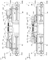
以下に本発明を実施するための最良の形態を図面を用いて説明する。図1(A)は、本発明のネジ溝検出装置80を備えた工作機械1の一実施の形態の概略外観図(平面図)を示しており、図1(B)は当該工作機械1(この場合、ネジ研削盤)の概略外観図(側面図)の例を示している。なお、図1(B)では、ワークWと接触子83と砥石22の位置関係を説明するために、主軸装置30R、30L等を省略している。
また、図2(A)及び(B)は、主軸装置30L、30Rを用いてワークWを支持する様子を示している。
なお、全ての図面において、X軸、Y軸、Z軸は直交しており、Y軸は鉛直上方を示しており、Z軸はワークWの回転軸CWと平行な水平方向を示しており、X軸はZ軸に直交する水平方向を示している。
The best mode for carrying out the present invention will be described below with reference to the drawings. FIG. 1A shows a schematic external view (plan view) of an embodiment of a
2A and 2B show how the workpiece W is supported using the
In all the drawings, the X axis, the Y axis, and the Z axis are orthogonal to each other, the Y axis indicates a vertically upward direction, the Z axis indicates a horizontal direction parallel to the rotation axis CW of the workpiece W, The X axis indicates the horizontal direction orthogonal to the Z axis.
●[工作機械1の構成(図1、図2)]
図1(A)、及び図2(A)、(B)に示すように、工作機械1には、主軸装置30L、30R(一対の工作物支持手段)が対向配置されており、主軸装置30LはリニアガイドGLに沿ってZ軸方向(工作物回転軸に平行な方向)に移動可能であり、主軸装置30RはリニアガイドGRに沿ってZ軸方向に移動可能である。
制御手段50(制御装置)は、主軸装置30L、30R用のZ軸方向駆動モータ30LM、30RMに駆動信号を出力し、検出手段30LE、30RE(エンコーダ等)からの検出信号を取り込み、主軸装置30L、30RのZ軸方向における位置及び移動速度等を制御可能である。例えば図2(A)及び(B)に示すように、Z軸方向駆動モータ30LM(30RM)は、ボールネジBL(BR)を回転させ、当該ボールネジBL(BR)にナット等で嵌合されたアームCL(CR)を移動させ、アームCL(CR)に接続された主軸装置30L(30R)を移動させる。
● [Configuration of machine tool 1 (FIGS. 1 and 2)]
As shown in FIGS. 1 (A), 2 (A), and 2 (B), the
The control means 50 (control device) outputs drive signals to the Z-axis direction drive motors 30LM, 30RM for the
また、工作機械1には、リニアガイドGZに沿ってZ軸方向に移動可能な砥石台10が載置されている。そして、砥石台10の上には、リニアガイドGXに沿って砥石台10に対してX軸方向に移動可能な砥石テーブル20が載置されている。また、砥石テーブル20には、砥石駆動モータ21及び砥石22(加工工具に相当)が設けられている。
制御手段50は、砥石台10用のZ軸方向駆動モータ10Mに駆動信号を出力し、検出手段10E(エンコーダ等)からの検出信号を取り込み、砥石台10のZ軸方向における位置及び移動速度等を制御可能である。また同様に、制御手段50は、砥石テーブル20用のX軸方向駆動モータ20Mに駆動信号を出力し、検出手段20Eからの検出信号を取り込み、砥石テーブル20のX軸方向における位置及び移動速度等を制御可能であり、砥石駆動モータ21に駆動信号を出力し、砥石22の回転を制御可能である。なお、砥石駆動モータ21に検出手段を設ければ、砥石22の回転速度を制御可能である。
また、図1(A)に示す工作機械1には、主軸装置30Lに砥石22を成形するツルーイング装置60が設けられている。
The
The control means 50 outputs a drive signal to the Z-axis direction drive
Further, the
また、工作機械1には、ワークWの少なくとも一部の円筒面に形成されたネジ部Kのネジ溝に当接させる接触子83と、接触子83を保持する保持手段81と、保持手段81をワーク回転軸CWに直交する方向に移動可能な検出体移動手段82とで構成されたネジ溝検出装置80が、支持体84上に設けられている(図1(B)参照)。
なお、図1(B)に示す例では、ワーク回転軸CWと砥石回転軸CTと接触子83は同一水平面(XZ平面)上に設定されており、接触子83は、砥石22が接触するワークWの反対側(180度回転した側)の位置のネジ溝を検出する。
このため、接触子83にて検出したネジ溝位置(Z軸方向の位置)を、角度θに基づいて補正したZ軸方向の位置(例えば、角度θが180度の場合、ネジ溝のピッチ(間隔)の1/2(180/360)を加えた位置)が、砥石22と対向するネジ溝の位置となる(あるいは、ネジ溝位置を検出後、ワークWを角度θだけ回転させて検出した面を砥石22に対向させる)。
なお、「ネジ溝の位置」とは、「ネジ溝の中心の位置」を指す。
Further, the
In the example shown in FIG. 1B, the workpiece rotation axis CW, the grindstone rotation axis CT, and the
Therefore, the position of the screw groove detected by the contactor 83 (position in the Z-axis direction) is corrected based on the angle θ (for example, when the angle θ is 180 degrees, the pitch of the screw groove ( The position obtained by adding 1/2 (180/360) of the interval) is the position of the thread groove facing the grindstone 22 (or after detecting the position of the thread groove, the workpiece W is detected by rotating it by an angle θ). The surface faces the grindstone 22).
The “position of the screw groove” refers to the “position of the center of the screw groove”.
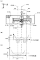
また、図1(C)にワークWの外観の例を示す。本実施の形態にて説明する工作機械1が対象とするワークWは、ワークWの少なくとも一部の円筒面にネジ溝が形成されたワークWを対象とする。図1(C)は、上記の対象内容に合致するEPS(Electric Power Steering)のステアリングロッドの外観を示しており、当該ステアリングロッドは、ネジ溝が形成されたネジ部Kの他にも、ラック&ピニオンの構造におけるラック部KR(円筒面の一部を平面状にして、ピニオンギアが嵌合する溝が形成された形状)が形成されている。
FIG. 1C shows an example of the appearance of the workpiece W. The workpiece W targeted by the
主軸装置30L(ワーク回転手段に相等)は、主軸台31Lと、ワーク回転軸回りに回転するスピンドル部32Lと、スピンドル部32Lと一体となって回転するとともに挿入されたワークWの円筒面を支持可能なチャック爪34Lを備えたチャック部33Lとで構成されている。また、スピンドル部32Lとチャック部33Lは、同軸上に(ワーク回転軸上に)設けられており、ワークWをZ軸方向に挿入可能な径を有する穴部が形成されている。制御手段50は、チャック爪34Lの開閉を制御可能であり、スピンドル部32Lの回転を制御可能である。また、主軸装置30R、主軸台31R、スピンドル部32R、チャック部33R、チャック爪34Rについては、上記に説明した主軸装置30Lと同様であるので説明を省略する。
The
ここで、図1(C)に示すワークWの場合、ネジ部Kの両端の近傍を支持しようとすると、ラック部KRの部位の支持が必要となる。しかし、ラック部KRの面をチャック爪34Lまたは34Rで支持(把持)するのは適切でない。チャック爪34Lまたは34Rで支持(把持)する場合、ラック部KRの面を回避してワークWの円筒面を支持することが好ましい。
そこで、図1(C)に示すように、ワークWの端面には、ワークWの回転角度を特定可能な位置決め溝WMが形成されている(例えば、ラック部KRの面と平行な方向に位置決め溝WMが形成されている)。なお、位置決め溝WMは、少なくとも一方の端面に形成されていればよい。
なお、本実施の形態では、図2(A)及び(B)に示すように、仮受け台73、74上に載置したワークWにおけるラック部KRの側の端面を主軸装置30R側に挿入し、ラック部KRと反対側の端面を主軸装置30Lに挿入している。従って、チャック部33Lで支持するワークWの部位は、円周上のどの位置を支持しても円筒面であるので、チャック爪34Lが3つ爪のチャック部33Lを用いることが好ましい(図示省略)。また、チャック爪33Rで支持するワークWの部位は、円周上にラック部KRが有るため、これを回避して円筒部を支持できるように、チャック爪34Rが2つ爪のチャック部33Rを用いることが好ましい(図示省略)。
なお、仮受け台73、74に載置されたワークWをチャック部33L、33Rにて保持すると、ワークWは仮受け台73、74から僅かに浮き上がる。
Here, in the case of the workpiece W shown in FIG. 1C, if it is intended to support the vicinity of both ends of the screw portion K, it is necessary to support the portion of the rack portion KR. However, it is not appropriate to support (grip) the surface of the rack portion KR with the
Therefore, as shown in FIG. 1C, a positioning groove WM capable of specifying the rotation angle of the workpiece W is formed on the end surface of the workpiece W (for example, positioning in a direction parallel to the surface of the rack portion KR). A groove WM is formed). The positioning groove WM only needs to be formed on at least one end face.
In the present embodiment, as shown in FIGS. 2A and 2B, the end surface on the rack portion KR side of the workpiece W placed on the
When the workpiece W placed on the
また、位置決め溝WMが形成された端面が挿入されるスピンドル部32Rの穴部には、位置決め溝WMに嵌合してZ軸方向に移動可能であるとともにスピンドル部32Rと一体となって回転する嵌合部材35Rが設けられている。嵌合部材35Rは、弾性部材(図示省略)にてワークWの側(位置決め溝WMに嵌合する方向)に付勢されており当該弾性部材は、制御手段50からの制御信号によってスピンドル部32R内においてZ軸方向に移動可能な調整部材(図示省略)に設けられている。
また、位置決め溝WMが形成されていない端面が挿入されるスピンドル部32Lの穴部には、ワークWの端面が当接する当接部材35Lと、Z軸方向に移動可能で当接部材35LのZ軸方向の位置を制御する調整部材(図示省略)が設けられている。
上記の説明では、ワークWの位置決め溝WMをラック部KRの側の端面のみに形成した例を説明したが、位置決め溝WMをワークWの両端面に形成してもよい。その場合、スピンドル部32L内の当接部材35Lを嵌合部材35Rと同様の部材とすればよい。
Further, the hole portion of the
Further, in the hole portion of the
In the above description, the example in which the positioning groove WM of the workpiece W is formed only on the end surface on the rack portion KR side, but the positioning groove WM may be formed on both end surfaces of the workpiece W. In that case, the
●[ネジ溝検出装置80の構成(図3)]
次に図3を用いて、ネジ溝検出装置80の構成について説明する。なお、図3は構成を説明するための模式図(平面図)であり、実際のネジ溝検出装置80の外観を示すものではない。図3のネジ溝検出装置80の実際の概略側面図は、図4(B)の例に示す外観から支持補助部材81C、82Gを省略した外観であり、検出体移動手段82は実際には保持ベース81Bの下に配置されている。また、図3のネジ溝検出装置80の実際の概略斜視図は、図5(B)の例に示す外観から検出体ずれ量検出手段84Sを省略した外観である。
ネジ溝検出装置80は、少なくとも測定対象のネジ溝WNに接触させる接触子83と、接触子83がワーク回転軸CWに平行なリード方向(Z軸方向)において基準線STZから往復移動可能となるように保持されるフローティング手段と、ワーク回転軸CWに直交する径方向に接触子83を付勢する付勢手段とを備えている。なお、基準線STZについては後述する。
● [Configuration of thread groove detection device 80 (FIG. 3)]
Next, the configuration of the thread
The thread
ここで、フローティング手段は、接触子83を保持した保持体81Aのリード方向の移動を案内する2本のガイド81Gと、ガイド81Gのほぼ中央に保持体81Aを維持する弾性部材81BR、81BLにて構成されている。これにより、保持体81A(接触子83)は、接触子83が何も接触していない場合における位置から、ガイド81Gに沿って、保持ベース81Bに対してリード方向に往復移動することが可能である。
また、付勢手段は、保持体81Aに対して径方向(ワーク回転軸CWに直交する方向であり、この場合はX軸方向)に移動可能となるように保持された接触子83を径方向に付勢する弾性部材81BBにて構成されている。
また、接触子83の先端には、ネジ溝WNの幅に収まる径の球状部材が固定されており、ネジ溝WNに入った場合、ネジ溝WNの中心に案内される構成を有している。
Here, the floating means is composed of two
Further, the urging means moves the
In addition, a spherical member having a diameter that fits within the width of the screw groove WN is fixed to the tip of the
また、保持手段81は、上記のフローティング手段と、付勢手段と、更に、リード側センサ81SR、81SL(リード側位置検出手段に相当)と、径側センサ81SB(径側位置検出手段に相当)とを備えている。
リード側センサは第1リード側センサ81SR(第1リード側位置検出手段に相当)と第2リード側センサ81SL(第2リード側位置検出手段に相当)との2個で構成されている。第1リード側センサ81SRは接触子83に対してリード方向の一方の側(この場合、右側)の保持ベース81Bに固定されており、第2リード側センサ81SLは接触子83に対してリード方向の他方の側(この場合、左側)の保持ベース81Bに固定されている。
第1リード側センサ81SRは、例えば非接触式センサであり、保持体81Aまでの距離(この場合、左方向への距離)を検出可能である。
第2リード側センサ81SLは、例えば非接触式センサであり、保持体81Aまでの距離(この場合、右方向への距離)を検出可能である。
The holding means 81 includes the floating means, the biasing means, the lead side sensors 81SR and 81SL (corresponding to the lead side position detecting means), and the diameter side sensor 81SB (corresponding to the diameter side position detecting means). And.
The lead side sensor is composed of two parts, a first lead side sensor 81SR (corresponding to first lead side position detecting means) and a second lead side sensor 81SL (corresponding to second lead side position detecting means). The first lead side sensor 81SR is fixed to the holding
The first lead side sensor 81SR is, for example, a non-contact sensor, and can detect the distance to the holding
The second lead side sensor 81SL is a non-contact sensor, for example, and can detect the distance to the holding
本実施の形態では、対向配置した2個のリード側センサ81SR、81SLの間に接触子83(保持体81A)を配置し、第1リード側センサ81SRからの検出信号と、第2リード側センサ81SLからの検出信号との比を用いて、第1リード側センサ81SRと第2リード側センサ81SLの間における、どの位置に接触子83が位置しているかを求める。
例えば、距離が大きくなるにつれて検出信号の出力が大きくなる特性の場合において、第1リード側センサ81SRから測定対象までの距離がL1、検出信号の出力がm1、第2リード側センサ81SLから測定対象までの距離がL2、検出信号の出力がm2であったとする。この場合、m1:m2=L1:L2の式が成立し、またL1+L2は所定距離であるので、これらの式を用いて、距離L1、L2を求めることができる。この場合、比を用いることで、温度ドリフト等によりm1及びm2が大きくなる方向に、または小さくなる方向にずれても誤差を相殺できるので、1個のリード側センサを用いた場合よりも、小さな誤差で接触子83のリード側の位置を検出することができる。
なお、本実施の形態では、第1リード側センサ81SRと第2リード側センサ81SLのリード方向の中間位置に基準点を設け、当該基準点を通るX軸に平行な基準線STZを設定している。制御手段50は、この基準点の位置(X座標、Y座標、Z座標)を認識しており、当該基準点を通る基準線STZから接触子83までのZ軸方向の距離を求めて、ネジ溝の位置を求める。
In the present embodiment, a contactor 83 (holding
For example, in the case where the detection signal output increases as the distance increases, the distance from the first lead side sensor 81SR to the measurement target is L1, the detection signal output is m1, and the second lead side sensor 81SL is the measurement target. And the output of the detection signal is m2. In this case, the equation m1: m2 = L1: L2 is established, and L1 + L2 is a predetermined distance. Therefore, using these equations, the distances L1 and L2 can be obtained. In this case, by using the ratio, the error can be canceled even if it deviates in the direction in which m1 and m2 increase or decrease due to temperature drift or the like, so it is smaller than in the case of using one lead side sensor. The position on the lead side of the
In this embodiment, a reference point is provided at an intermediate position in the lead direction of the first lead side sensor 81SR and the second lead side sensor 81SL, and a reference line STZ parallel to the X axis passing through the reference point is set. Yes. The control means 50 recognizes the position of the reference point (X coordinate, Y coordinate, Z coordinate), obtains the distance in the Z-axis direction from the reference line STZ passing through the reference point to the
また、径側センサ81SBは、例えば非接触式のセンサであり、保持体81Aの後方に固定され、接触子83の端面までの距離(図3(B)の例では、X軸方向の距離Lx)を検出可能である。
そして図3の例に示すネジ溝検出装置80は、更に、保持手段81をワーク回転軸CWに直交する方向に移動可能な検出体移動手段82と、制御手段(この場合、制御手段50(図1(A)参照))とを備えている。
図3に示す例では、検出体移動手段82はシリンダとピストン82Aとで構成されており、保持手段81をワーク回転軸CWから最も遠ざかる位置(図3(A)に示す位置)、または保持手段81をワーク回転軸CWに最も近接する位置(図3(B)に示す位置)のいずれかの位置に移動可能である。
制御手段50は、図3(A)に示す位置と図3(B)に示す位置における前記基準点の位置を認識しており、更に、接触子83のX軸方向の長さも認識している。従って、径側センサ81SBから接触子83の端面までの距離Lxを求めることで、接触子83の先端部におけるX軸方向の位置を認識可能であり、接触子83の先端のX軸方向の位置に基づいて、接触子83がネジ溝WNに入ったか否かを判定することが可能である。
以上の構成により、ネジ溝検出装置80をコンパクトに収めることができ、図1(A)及び(B)に示すように、工作機械1への搭載も容易である。
Further, the diameter side sensor 81SB is, for example, a non-contact type sensor, and is fixed to the rear of the holding
3 further includes a detection body moving means 82 that can move the holding means 81 in a direction orthogonal to the workpiece rotation axis CW, and a control means (in this case, the control means 50 (FIG. 1 (A))).
In the example shown in FIG. 3, the detection body moving means 82 is composed of a cylinder and a
The control means 50 recognizes the position of the reference point at the position shown in FIG. 3A and the position shown in FIG. 3B, and also recognizes the length of the
With the above configuration, the thread
●[ネジ溝検出装置80のその他の構成(図4〜図6)]
図3の模式図に示すネジ溝検出装置80に対して、ネジ溝WNのZ軸方向の位置を更に高精度に検出可能なネジ溝検出装置80の模式図の例を図4〜図6に示す。図3に示すネジ溝検出装置80は、保持手段81をワーク回転軸CWに最も近接する位置に移動させて接触子83をワークWに接触させた場合、ピストン82A上のいずれかの位置を支点として保持手段81がXZ平面内で回転等する可能性があり、この場合、回転角度に応じて、検出したネジ溝WNのZ軸方向の位置に誤差が発生する可能性がある。
● [Other configuration of thread groove detection device 80 (FIGS. 4 to 6)]
4 to 6 show examples of schematic views of the screw
そこで、図4に示すように、嵌合して回転を抑制する支持補助部材82G、81Cを追加する。支持補助部材82Gは検出体移動手段82等の任意の固定部材に固定されており、支持補助部材81Cは可動する保持手段81に固定されている。そして、保持手段81をワーク回転軸CWに最も近接する位置に移動させた場合に、支持補助部材82G、81Cが嵌合され、支持補助部材81Cが支持補助部材82Gに案内される構造を有している。なお、図4(A)に示す例では、支持補助部材82Gにおける可動部材82Fが支持補助部材81Cを挟むように可動し、より強固に固定できる構造を示している。
Accordingly, as shown in FIG. 4,
また、図5に示す例では、支持補助部材82G、81Cに加えて、更に、保持手段81のZ軸方向へのずれ量を検出する検出体ずれ量検出手段84Sが追加されている。なお、図5(B)に示す斜視図では、ピストン82Aを省略している。
検出体ずれ量検出手段84Sは任意の固定体に固定されており、図5の例では、検出体移動手段82に固定した支持体84に固定されている。検出体ずれ量検出手段84Sは、例えば非接触センサであり、制御手段50は、検出体ずれ量検出手段84Sからの検出信号に基づいて、検出体ずれ量検出手段84Sから保持手段81までのZ軸方向の距離を検出し、保持手段81のZ軸方向のずれ量を検出することが可能である。そして、制御手段50は、接触子83のZ軸方向の位置を求めた後、検出体ずれ量検出手段84Sから求めたリード方向のずれ量を用いて、ネジ溝WNのZ軸方向の位置を補正する。
この場合、まず接触子83をネジ溝に接触させる前に検出体ずれ量検出手段84Sからの検出信号に基づいて、検出体ずれ量検出手段84Sから保持ベース81Bまでの距離(距離B)を求めておく。そして、接触子83をネジ溝に接触させてリード方向における接触子83の位置(位置A)を求めた後、検出体ずれ量検出手段84Sからの検出信号に基づいて、検出体ずれ量検出手段84Sから保持ベース81Bまでの距離(距離B´)を求める。そして、距離Bと距離B´の差分(ずれ量)に基づいて、求めた位置Aを補正する。
これにより、ネジ溝のZ軸方向の位置の検出精度を、より向上させることができる。また、支持補助部材81C、82Gを高精度化する必要がなくなるので、ネジ溝検出装置80のコストを抑えることができる。
Further, in the example shown in FIG. 5, in addition to the support
The detection body deviation amount detection means 84S is fixed to an arbitrary fixed body, and is fixed to a
In this case, first, before the
Thereby, the detection accuracy of the position of the screw groove in the Z-axis direction can be further improved. In addition, since it is not necessary to increase the accuracy of the supporting
また、図6に示す例では、図5の保持手段81から検出体ずれ量検出手段84Sを省略し、更に、リード側センサ81SR、81SLを、保持ベース81Bに固定する代わりに任意の固定体に固定しており、リード側センサ81SR、81SLを、検出体移動手段82に固定した支持体84に固定している。なお、図6(B)に示す斜視図では、ピストン82Aを省略している。
図6に示す例では、保持手段81がZ軸方向にずれても、ずれ量を含めて接触子83のZ軸方向の位置を検出できる。
これにより、ネジ溝のZ軸方向の位置の検出精度を、より向上させることができる。また、支持補助部材81C、82Gを高精度化する必要がなくなるので、ネジ溝検出装置80のコストを抑えることができる。
Further, in the example shown in FIG. 6, the detection body deviation amount detection means 84S is omitted from the holding means 81 of FIG. 5, and the lead side sensors 81SR and 81SL are fixed to any fixed body instead of being fixed to the holding
In the example shown in FIG. 6, even if the holding means 81 is displaced in the Z-axis direction, the position of the
Thereby, the detection accuracy of the position of the screw groove in the Z-axis direction can be further improved. In addition, since it is not necessary to increase the accuracy of the supporting
以上に説明したネジ溝検出装置80を用いたネジ溝の位置の検出方法における第1の実施の形態〜第4の実施の形態を、以降で説明する。なお、以降の説明では、図3に示すネジ溝検出装置80を用いた場合で説明を行うが、図4及び図6に示すネジ溝検出装置80を用いた場合も同様であるので、それらの説明は省略する。また、図5に示すネジ溝検出装置80を用いた場合は、上記に記載したように求めた接触子83の位置を補正すればよいので説明を省略する。
また、第1の実施の形態〜第4の実施の形態に示す処理手順の例は、制御手段50の動作を指示するプログラムに記載されている。
The first to fourth embodiments of the method for detecting the position of the thread groove using the thread
In addition, examples of processing procedures shown in the first to fourth embodiments are described in a program that instructs the operation of the control means 50.
●[第1の実施の形態におけるネジ溝の位置の検出方法]
次に、ネジ溝WNのZ軸方向の位置を検出する第1の実施の形態の手順を説明する。
制御手段50は、図3(A)に示すように保持手段81をワーク回転軸CWから最も遠ざかる位置から検出体移動手段82に駆動信号を出力し、保持手段81をワーク回転軸CWに向けて(ワークWのネジ溝に向けて)前進させる。
そして、制御手段50は、保持手段81をワーク回転軸CWに最も近接する位置に移動させて接触子83をワークWに接触させる。ここで、制御手段50は、接触子83がネジ溝WNに入った場合において、径側センサ81SBによって検出されるべき接触子83の端面までの距離Lxを認識している。そして、制御手段50は、径側センサ81SBからの検出信号に基づいて求めた距離が距離Lx近傍の値である場合(例えば判定閾値をΔxとした場合、求めた距離が、距離Lx±Δx以内の場合)は、接触子83がネジ溝WNに入ったと判定し、距離Lx近傍の値でなく、距離Lxよりも小さい値(例えば距離Lx−Δxより小さい値)である場合、接触子83がネジ溝WNに入っていないと判定する。
[Method of detecting the position of the thread groove in the first embodiment]
Next, the procedure of the first embodiment for detecting the position of the screw groove WN in the Z-axis direction will be described.
As shown in FIG. 3A, the control means 50 outputs a drive signal to the detection body moving means 82 from a position where the holding means 81 is farthest from the work rotation axis CW, and directs the holding means 81 toward the work rotation axis CW. Advance (toward the thread groove of the workpiece W).
Then, the
保持手段81をワーク回転軸CWに近接させて接触子83をネジ溝WNに接触させた際、接触子83の先端の移動先にちょうどネジ溝WNがある場合、接触子83はリード方向に移動しない。しかし、移動先にちょうどネジ溝WNがある場合よりも、ずれている場合の方が多い。図3(B)の例は、ネジ溝WNのリード方向の位置が、基準線STZに対して−Δzずれている場合を示している。制御手段50は、リード側センサ81SR、81SLからの検出信号に基づいて、接触子83における基準線STZからの距離(−Δz)を求めることができる。
制御手段50は、工作機械1上における保持手段81の基準点の位置(ワーク回転軸CWに最も近接した図3(B)の状態における基準点の位置(X座標、Y座標、Z座標))を認識している。そして制御手段50は、保持手段81の工作機械1上のZ軸方向の位置、保持手段81に対する基準線STZ(基準点)からのZ軸方向の距離(−Δz)等から、接触子83の先端が接触しているネジ溝WNの工作機械1上におけるZ軸方向の位置を求めることができる。
When the holding means 81 is brought close to the workpiece rotation axis CW and the
The control means 50 is the position of the reference point of the holding means 81 on the machine tool 1 (the position of the reference point (X coordinate, Y coordinate, Z coordinate) in the state of FIG. 3B closest to the workpiece rotation axis CW). Recognize. Then, the control means 50 determines the position of the
●[第2の実施の形態におけるネジ溝の位置の検出方法(図7)]
以上に説明した第1の実施の形態では、接触子83がネジ溝WNに接触するように保持手段81を近接させた際、接触子83がネジ溝WNに入ることを想定しているが、接触子83がネジ溝WNに入らない場合も考えられる。例えば、図10(B)に示すようなボールネジのネジ溝では、ネジ溝の幅に対してネジ溝の両肩部の幅のほうが数倍も長く、ネジ溝に入る確率よりも、ネジ溝に入らない確率のほうが高いと考えられる。
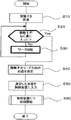
そこで、第2の実施の形態では、接触子83をネジ部Kに当接させたがネジ溝WNに入っていないと検出した場合、積極的に接触子83をネジ溝WNに入れる処理を追加している。以下、図7に示すフローチャートを用いて説明する。
● [Method of detecting the position of the thread groove in the second embodiment (FIG. 7)]
In the first embodiment described above, it is assumed that the
Therefore, in the second embodiment, when it is detected that the
制御手段50は、ステップS10にて、検出体移動手段82に駆動信号を出力し、ワーク回転軸CWに直交する方向に保持手段81を前進させて、ワークWのネジ部Kに接触子83を接触させ、ステップS20に進む。
ステップS20にて、制御手段50は、径側センサ81SBからの検出信号に基づいて、接触子83がネジ溝WNに入ったか否かを判定する。接触子83がネジ溝WNに入った(Yes)と判定した場合はステップS40に進み、ネジ溝WNに入っていない(No)と判定した場合はステップS30に進む。
In step S <b> 10, the
In step S20, the control means 50 determines whether or not the
ステップS30に進んだ場合、制御手段50は、主軸装置30L、30Rに制御信号を出力し、ワークWをワーク回転軸CW回りに回転させて、接触子83をネジ溝WNに入れに行く。接触子83がネジ溝WNに入っていない場合、少なくともワークWを1回転させれば、必ずネジ溝WNが接触子83の先端に到達し、接触子83がネジ溝WNに入る。従って、ステップS30にてワークWを1回転させて、ステップS20にてネジ溝WNに入ったことを確認してステップS40に進む。なお、ワークWを1回転させずに、ステップS20の判定を行いながらステップS30のワークWの回転を行い、接触子83がネジ溝WNに入ったことを検出した場合に、ワークWの回転を停止してステップS40に進んでもよい。
第2の実施の形態では、このステップS20とステップS30によって、接触子83をネジ部Kに接触させたときにネジ溝WNに入らない場合であっても、接触子83を適切にネジ溝WNに入れることができる。
When the process proceeds to step S30, the control means 50 outputs a control signal to the
In the second embodiment, even if the
そして、ステップS40にて、制御手段50は、リード側センサ81SR、81SLからの検出信号に基づいて、接触子83における基準線STZからのZ軸方向の距離(−Δz)を求め、ステップS50に進む。
ステップS50では、求めた距離、または距離から求めたネジ溝WNのZ軸方向の位置を、ネジ溝WNを加工工具で研削する際のパラメータとして入力する。
なお、保持手段81と検出体移動手段82とを備えたネジ溝検出装置80が、図1に示す位置(ワーク回転軸CWを挟んで加工工具と対向する位置)にある場合、ワークWを180度回転させて、求めたネジ溝WNの位置が加工工具の側に向くようにする。
あるいは、ステップS50にてワークWを更に1回転させて(あるいは所定角度回転させて)、再度、接触子83における基準線STZからのZ軸方向の距離を求め、ステップS40で求めた距離との差分から、ネジ溝WNのピッチを求め、当該ピッチに基づいて、加工工具の側のネジ溝WNのZ軸方向の位置を補正するようにしてもよい。
そして、ステップS60では、求めたネジ溝WNのZ軸方向の位置を用いて、加工工具をネジ溝WNの位置に位置決めし、ネジ溝WNを研削加工する。
In step S40, the control means 50 obtains the distance (−Δz) in the Z-axis direction from the reference line STZ in the
In step S50, the obtained distance or the position in the Z-axis direction of the screw groove WN obtained from the distance is input as a parameter for grinding the screw groove WN with a processing tool.
When the thread
Alternatively, the workpiece W is further rotated once (or rotated by a predetermined angle) in step S50, and the distance in the Z-axis direction from the reference line STZ in the
In step S60, using the obtained position of the screw groove WN in the Z-axis direction, the machining tool is positioned at the position of the screw groove WN, and the screw groove WN is ground.
●[第3の実施の形態におけるネジ溝の位置の検出方法(図8)]
以下に説明する第3の実施の形態では、接触子がネジ溝WNに入った後、接触子83のバックラッシュ等の影響による誤差を抑制する処理が追加されている。例えば、同じ位置のネジ溝に対して、右から近づいた場合と左から近づいた場合とでは、同じ位置であるはずだが、僅かに異なる場合等がある。
第3の実施の形態では、このバックラッシュ等の誤差を低減するために、リード方向の位置の測定の前に、接触子83を、所定の方向(リード方向における一方の方向)に、所定の距離だけ移動させる。以下、図8に示すフローチャートを用いて説明する。
● [Method of detecting the position of the thread groove in the third embodiment (FIG. 8)]
In the third embodiment described below, processing for suppressing errors due to the influence of backlash or the like of the
In the third embodiment, in order to reduce errors such as backlash, the
ステップS10〜ステップS30は、図7に示す第2の実施の形態と同様であるので説明を省略する。
接触子83がネジ溝WNに入ったと判定した後、ステップS36では、制御手段50は、接触子83をネジ溝WNになじませるため、ワークWを微小回転角度で往復回転する。なお、往復回転の回転角度と往復回数は任意である。
そして、ステップS37では、制御手段50は、バックラッシュ等の誤差の発生を抑制するために、ワークWを所定方向に所定角度だけ回転させる。例えば、図3(B)において接触子83が右方向に移動する方向に、ワークWを180度回転させる。
以下、ステップS40〜ステップS60の処理は、第2の実施の形態の説明と同様であるので説明を省略する。
なお、ステップS36の往復回転は省略してもよい。
Steps S10 to S30 are the same as those in the second embodiment shown in FIG.
After determining that the
In step S37, the control means 50 rotates the workpiece W by a predetermined angle in a predetermined direction in order to suppress the occurrence of errors such as backlash. For example, the workpiece W is rotated 180 degrees in the direction in which the
Hereinafter, the processing of step S40 to step S60 is the same as that described in the second embodiment, and thus the description thereof is omitted.
The reciprocating rotation in step S36 may be omitted.
●[第4の実施の形態におけるネジ溝の位置の検出方法(図9)]
以下に説明する第4の実施の形態では、接触子83のリード方向の位置を最も小さな誤差で検出できる位置となるように、接触子83がネジ溝WNに入った後、ワークWを回転させて、リード方向の位置の誤差が最も小さな誤差となる位置に接触子83を移動させる。なお、接触子83のリード方向の位置を最も小さな誤差で検出できる位置は、リード側センサの特性に基づいて、適切な位置(所定位置)を設定すればよく、本実施の形態の説明では、基準線STZの位置を「最も小さな誤差となる位置」として説明する。
図3(A)及び(B)に示すように、本実施の形態では、接触子83をリード方向(Z軸方向)に往復移動可能となるようなフローティング機構を備え、第1リード側センサ81SRと第2リード側センサ81SLの検出信号の比でZ軸方向の位置を求めており、例えば、第1リード側センサ81SRと第2リード側センサ81SLの中間点である基準点の位置が、最も小さな誤差となる位置であるものとして所定位置に設定し、以下、図9に示すフローチャートを用いて説明する。なお、この所定位置をリード側センサ81SR、81SLの校正点としてもよい。
● [Method of detecting the position of the thread groove in the fourth embodiment (FIG. 9)]
In the fourth embodiment described below, after the
As shown in FIGS. 3A and 3B, in this embodiment, the first lead-side sensor 81SR is provided with a floating mechanism that enables the
ステップS10〜ステップS30は、図7に示す第2の実施の形態と同様であるので説明を省略する。
接触子83がネジ溝WNに入ったと判定した後、ステップS32では、制御手段50は、リード側センサ81SR、81SLからの検出信号に基づいて、その時点での接触子83における基準線STZからの仮の距離を求め、ステップS33に進む。
ステップS33では、制御手段50は、接触子83における基準線STZからの距離が、ほぼゼロとなるようにワークWを回転させて、接触子83のZ軸方向の位置を、ほぼ基準線STZの位置に戻し、ステップS36に進む。
ステップS36〜ステップS60の処理は、第3の実施の形態の説明と同様であるので説明を省略する。
なお、ステップS37では、接触子83をリード方向におけるいずれかの方向に少し移動させるため、このステップS37による移動量を考慮に入れて、ステップS33における接触子83の移動先を補正すると、より好ましい。(ステップS37で接触子83を少し移動させるが、この移動の結果、ほぼ基準線STZの位置となるようにすることが、より好ましい。)また、ステップS37にて、所定方向と逆方向に所定角度回転させた後、所定方向に所定角度回転させてもよい。
なお、特に高い精度が要求されない場合は、ステップS36とステップS37の処理を省略してもよい。
Steps S10 to S30 are the same as those in the second embodiment shown in FIG.
After determining that the
In step S33, the control means 50 rotates the workpiece W so that the distance from the reference line STZ in the
Since the processing of step S36 to step S60 is the same as that of the third embodiment, the description thereof is omitted.
In step S37, since the
Note that the processing in steps S36 and S37 may be omitted if particularly high accuracy is not required.
以上、本実施の形態にて説明したネジ溝検出装置80は、ネジ溝WNの中心の位置を接触子83を接触させることで直接的に検出するので、ネジ溝WNのリード方向の位置の測定精度が高い。また、ネジ溝と肩部の境界を何往復もしていた従来の検出方法と比較して、非常に短時間にネジ溝の中心の位置を測定可能である。更に、ネジ溝検出装置80はコンパクトに構成することができるので、工作機械1に搭載することが容易である。
なお、本実施の形態の説明では、検出体移動手段82を用いて、接触子83をワークWに接触あるいは離間させたが、検出体移動手段82を省略して、接触子83をワークWに接触させた状態を保持するようにしてもよいし、作業者の操作で接触子83を接触または離間するように構成してもよい。
As described above, the thread
In the description of the present embodiment, the
以上に説明したネジ溝検出装置80を用いて、ネジ溝WNのリード方向の位置を測定し、更に、主軸装置30R、30L(ワーク回転手段に相当)にてワークWを所定角度だけ回転させて、ネジ溝検出装置80にて当該所定角度の回転における接触子83のリード方向の移動距離を測定してネジ溝WNのピッチを求める。
更に、測定したネジ溝WNのZ軸方向の位置に、砥石22(加工工具)を位置決めするようにZ軸方向駆動モータ10M(リード側移動手段に相当)を制御し、砥石22がネジ溝WNに入るようにX軸方向駆動モータ20M(径側移動手段に相当)を制御する。
そして、主軸装置30R、30Lを用いてワークWを回転させるとともに、測定したピッチに基づいて、Z軸方向駆動モータ10Mを用いて砥石22をリード方向に移動させて、ネジ溝WNを仕上げ研削する。
また、ネジ溝検出装置80は、ネジ溝WNの位置の測定後、砥石22を用いてネジ溝を研削する際は、元の位置(ワーク回転軸CWから(最も)遠ざかる位置)に戻し、ワークWから離間させておく。
なお、本実施の形態の説明では、ワークWに対して砥石22をX軸方向に移動させたが、砥石22に対してワークWをX軸方向に移動させる構成にすることもできる。従って、砥石22はワークWに対して相対的にX軸方向に移動するものである。
同様に、Z軸方向については、ワークWに対して砥石22をZ軸方向に移動させたが、砥石22に対してワークWをZ軸方向に移動させる構成にすることもできる。従って、砥石22はワークWに対して相対的にZ軸方向に移動するものである。
Using the screw
Further, the Z-axis direction drive
And while rotating the workpiece | work W using the
In addition, after measuring the position of the thread groove WN, the thread
In the description of the present embodiment, the
Similarly, with respect to the Z-axis direction, the
●[第5の実施の形態におけるネジ溝検出装置の構成とネジ溝検出方法(図12)]
以下に説明する第5の実施の形態では、図3(A)及び(B)〜図6(A)及び(B)に示すネジ溝検出装置80において、第1リード側センサ81SRと第2リード側センサ81SLの位置をリード方向にオフセットさせている(図12(A)の例では、左側に距離Zofだけずらしている)。なお、図12(A)は、図3(A)に示すネジ溝検出装置80からの変更個所の説明に必要な部分を抜き出したものであり、検出体移動手段82等の記載を省略している。
● [Configuration of Thread Detection Device and Thread Detection Method in Fifth Embodiment (FIG. 12)]
In the fifth embodiment described below, in the thread
フローティング手段は、リード方向(この場合、Z軸方向)に沿う押付け力または引張り力を発生させる弾性手段(この場合、弾性部材81BR、81BL)によって、ワークWまたはネジ溝WNに接触していない状態の接触子83のリード方向の位置を中立位置(この場合、基準線STZの位置)に保持している。また、フローティング手段は、接触子83の中立位置からのリード方向の距離に応じて、接触子83を中立位置に戻すための押付け力または引張り力を発生させる。
図12(B)は、接触子83におけるリード方向の可動範囲において、ネジ溝WNのリード方向の位置を任意の位置に固定し、接触子83を用いて当該ネジ溝WNのリード方向の位置を複数回検出した場合の誤差ErK(繰り返し誤差)の大きさを実測して求めた繰り返し誤差特性を示している。この繰り返し誤差特性(いわゆるバラツキ)の結果より、可動範囲の両端近傍では弾性手段による接触子83に加えられる力が大きいために誤差が大きくなり、中立位置の近傍では弾性手段による接触子83に加えられる力が小さいために不安定となり、誤差が大きくなっていると推定される。両端近傍及び中立位置近傍を除いた範囲(図12(B)における範囲Zα1、Zα2)では、接触子83に適度な力が加えられて安定した検出結果を得られており、誤差閾値ΔErK以下に抑えることができることを確認できた。
The floating means is not in contact with the workpiece W or the screw groove WN by the elastic means (in this case, the elastic members 81BR and 81BL) that generates a pressing force or a tensile force along the lead direction (in this case, the Z-axis direction). The position of the
FIG. 12B shows that the position of the screw groove WN in the lead direction of the
また、図12(C)は、接触子83におけるリード方向の可動範囲において、第1リード側センサ81SRと第2リード側センサ81SLによる、接触子83のリード方向の位置に対するセンサ誤差特性を示している。本実施の形態では、第1リード側センサ81SRと第2リード側センサ81SLには渦電流センサを用いており、リード方向における各センサ間の中心であるセンサ中心位置STLRに接触子83が有る場合に最も誤差が小さくなり、接触子83がセンサ中心位置STLRから遠ざかるに従って誤差が大きくなる。センサ中心位置STLRの近傍の範囲(図12(C)における範囲Zβ)では、誤差閾値ΔErS以下に抑えることができることを確認した。
FIG. 12C shows sensor error characteristics with respect to the position of the
従って、繰り返し誤差特性が誤差閾値ΔErK以下である範囲、且つセンサ誤差特性が誤差閾値ΔErS以下である範囲、となるリード方向の位置であれば、高精度にリード方向の位置を検出できることになる。そこで、第1リード側センサ81SRと第2リード側センサ81SLの配置位置を、リード方向に所定距離だけずらして配置する。図12の例では、図12(B)の繰り返し誤差特性の範囲Zα1のほぼ中央にセンサ中心位置STLRが位置するように、距離Zofだけずらしている。 Therefore, the position in the lead direction can be detected with high accuracy as long as the position in the lead direction is within a range where the repeat error characteristic is equal to or less than the error threshold ΔErK and the sensor error characteristic is equal to or less than the error threshold ΔErS. Therefore, the arrangement positions of the first lead-side sensor 81SR and the second lead-side sensor 81SL are arranged so as to be shifted by a predetermined distance in the lead direction. In the example of FIG. 12, the distance Zof is shifted so that the sensor center position STLR is positioned approximately at the center of the range Zα1 of the repeat error characteristic of FIG.
そして、接触子83をネジ溝WNに入れて、ネジ溝WNのリード方向の位置を検出する際、接触子83のリード方向の位置が、第1リード側センサ81SRと第2リード側センサ81SLの中央近傍(つまり、センサ中心位置STLRの近傍)となるように、ワークWを回転させて(あるいはネジ溝検出装置80をワークWに対して相対的にリード方向に移動させて)、ネジ溝WNのリード方向の位置を検出する。つまり、接触子83のリード方向の位置が第1リード側センサ81SRと第2リード側センサ81SLの中央近傍の位置であり、且つ接触子83に対してフローティング手段から接触子83を中立位置(基準線STZの位置)に戻す押付け力または引張り力による荷重がかかっている状態にして、ネジ溝WNのリード方向の位置を検出する。
この状態では、接触子83のリード方向の位置は、第1リード側センサ81SRと第2リード側センサ81SLの中央近傍であるので、センサ誤差特性(図12(C)参照)の誤差は充分小さい。また、繰り返し誤差特性(図12(B)参照)の誤差も充分小さいので、非常に高精度にネジ溝WNのリード方向の位置を検出することができる。
When the
In this state, since the position of the
●[第6の実施の形態におけるネジ溝の位置の検出方法(図13〜図15)]
以下に説明する第6の実施の形態では、図9を用いて説明した第4の実施の形態に対して、接触子83をネジ溝WNに入れた後の検出方法が異なる。図9に示す第4の実施の形体のフローチャートのステップS32〜ステップS37の処理が、図14に示す第6の実施の形体では、ステップS38A〜ステップS38Fに変更されている。この変更点を説明する前に、まず図13(A)及び(B)を用いて、接触子83のリード方向の位置が中立位置(基準線STZの位置)から離れるにつれてネジ溝WNの中心に収まらずに誤差が発生する様子を説明する。なお図13(A)及び(B)は、説明を容易にするために、接触子83と、接触子83に押し付け力や復元力を与える弾性部材(81BR、81BL、81BB)と、ネジ溝WN等を記載しており、他の部材の記載を省略している。
[Method of detecting the position of the thread groove in the sixth embodiment (FIGS. 13 to 15)]
The sixth embodiment described below differs from the fourth embodiment described with reference to FIG. 9 in the detection method after the
図13(A)は、中立位置(接触子83がワークWにもネジ溝WNにも接触していない場合のリード方向の位置であり、この場合、基準線STZの位置)にいる接触子83の正面にネジ溝WNの中心が位置していた場合に、接触子83をネジ溝WNに押し付けた状態を示している。
この場合は中立位置であることより、弾性部材81BL、81BRから接触子83に与えるリード方向の復元力がほぼゼロであるので、弾性部材81BBの押し付け力によって接触子83はネジ溝WNの中心に収まる。
中立位置にある接触子83をワークWに押し付けてワークWを回転させると、ネジ溝WNのネジ面NMに接触子83が接し始めると接触子83はネジ溝WNに入る。しかし、そのままワークWの回転を継続すると、ネジ溝WNに入った接触子83は、ネジ溝WNに案内されてリード方向に移動していく。
例えば図13(B)(細線、点線、一点鎖線、太線)の中の細線の状態では、ネジ溝WNの中心が中立位置(基準線STZの位置)からリード方向(この場合、左方向)に距離ΔLだけずれた位置の状態を示している。
FIG. 13A shows the
In this case, since the restoring force in the lead direction applied from the elastic members 81BL and 81BR to the
When the
For example, in the state of the thin line in FIG. 13B (thin line, dotted line, alternate long and short dash line, thick line), the center of the thread groove WN extends from the neutral position (position of the reference line STZ) to the lead direction (in this case, leftward). A state at a position shifted by a distance ΔL is shown.
接触子83がリード方向において中立位置から離れていくと、フローティング手段である弾性部材81BL、81BRにて、接触子83を中立位置に戻そうとする復元力Fbが働く。更に、この復元力Fbは、中立位置から接触子83までの距離が大きくなるにつれて大きくなる。
また、接触子83は、弾性部材81BBからの押し付け力Faにてワーク回転軸CWの方向に押し付けられている。
When the
The
ここで、図13(B)の点線円の中に、接触子83とネジ面NM、及び接触子83とネジ面NMとが当接する接点TPにおける復元力Fb、押し付け力Fa、及び接点TPに働く摩擦力Fmの状態を示す。
押し付け力Faを、ネジ面NMに平行な成分の力Fa1とネジ面NMに直交する成分の力Fa2に分解し、復元力Fbを、ネジ面NMに平行な成分の力Fb1とネジ面NMに直交する成分の力Fb2に分解する。また、接触子83は、ネジ面NMから力Fa2+力Fb2と同じ大きさで反対方向の抗力Fkを受ける。また接点TPにはネジ面NMに平行な摩擦力Fmが働いている。
これらより、接点TPでは、ネジ面NMに平行な力Fa1と力Fb1と摩擦力Fm、及びネジ面NMに直交する力Fa2と力Fb2と抗力Fkが釣り合い、当該位置で停止している。
この釣り合っている状態から、例えば接触子83が中立位置に近づくと復元力Fbが小さくなって力Fb1が小さくなり、力Fa1によって接触子83はワーク回転軸CWの方向に移動し、当該移動によって押し付け力Faが小さくなり、移動先で各力が釣り合って停止する。
Here, the restoring force Fb, the pressing force Fa, and the contact point TP at the contact point TP where the
The pressing force Fa is decomposed into a component force Fa1 parallel to the screw surface NM and a component force Fa2 orthogonal to the screw surface NM, and the restoring force Fb is converted into a component force Fb1 parallel to the screw surface NM and the screw surface NM. It decomposes into force Fb2 of the orthogonal component. Further, the
Accordingly, at the contact point TP, the forces Fa1, force Fb1, and friction force Fm parallel to the screw surface NM and the forces Fa2, force Fb2, and drag force Fk orthogonal to the screw surface NM are balanced and stopped at the position.
From this balanced state, for example, when the contactor 83 approaches the neutral position, the restoring force Fb decreases and the force Fb1 decreases, and the
接触子83がネジ溝WNの奥まで入らずに途中で停止してしまう状態を回避するために、以下の2通りの方法を考える。なお、ネジ溝WNの位置を測定する際は、より高精度に測定するために、複数回測定する。
第1の方法は、接触子83をネジ溝WNに入れた状態を維持して、接触子83が中立位置に近づくように移動させる方法である。第1の方法では、接触子83をネジ溝WNに入れた状態を維持しており、後述する第2の方法と比較して、複数回の測定において最も時間がかかる接触子83の前進回数が少ないので、測定のサイクルタイムを短くできる点と、押し付け力Faが小さいので、接触子83の耐久性が向上する点が有利である。しかし、後述する第2の方法に対して、接触子83を引きずるようにネジ溝WNで案内して移動させるので、上記のようにネジ溝WNの奥まで接触子83が到達しない場合があり、測定値が不安定になる点が不利である。
これに対して第2の方法は、押し付け力Faを大きくして、ネジ溝WNの途中で接触子83が停止しないように、より強い押し付け力でネジ溝WNの奥まで接触子83を到達させる方法である。第2の方法では、第1の方法と比較して、接触子83を安定してネジ溝83の奥に到達させることができるので測定値が安定する点で有利である。しかし、複数回の測定において接触子83の前進・後退の回数が多く、サイクルタイムが長くなる点と、強化した押し付け力にて接触子83にかかる衝撃が大きくなり、耐久性が低下する点で不利である。
以下に説明する本実施の形態では、上記の第1の方法を採用するとともに、押し付け力Faを強化することなく接触子83をネジ溝WNの奥まで到達させるようにして安定した測定値を得られるようにするものである。
In order to avoid a state where the
The first method is a method of moving the
On the other hand, in the second method, the pressing force Fa is increased so that the
In the present embodiment described below, the above-described first method is adopted, and a stable measurement value is obtained by allowing the
次に、図14に示すフローチャートと図13(B)を用いて本実施の形態の処理手順と、接触子83の状態の変化について説明する。なお、図9のフローチャートとの相違点であるステップS38A〜ステップS38Fについて説明する。
制御手段50は、ステップS20にて接触子83がネジ溝WNに入ったと判定した場合(Yes)はステップS38Aに進む。このときの接触子の状態を図13(B)の細線の接触子83(0)で示す。この場合、ネジ溝WNの中心の位置が中立位置(STZ)から距離ΔLだけ離れており、接触子83(0)がネジ溝WNの奥まで到達せずにネジ面NMの途中で停止している。
Next, the processing procedure of the present embodiment and the change in the state of the
If the control means 50 determines in step S20 that the
ステップS38Aでは、制御手段50は、リード側センサ81SR、81SLからの検出信号に基づいて、接触子83のリード方向の位置を測定し、ステップS38Bに進む。以下では、測定したこの位置を「落とし込み位置」と記載する。
ステップS38Bでは、落とし込み位置から、予め記憶している理想第1中継位置までのリード方向の距離(第1移動距離に相当)及び移動方向を求め、落とし込み位置にいる接触子83(0)を理想第1中継位置まで移動させる。ここで理想第1中継位置とは、中立位置(STZ)からリード方向の一方(この場合、左側に向かうリード方向)に第1所定距離(例えば300[μm]程度)だけ離れた位置であり、予め設定された位置である。なお、通常、リード側センサ81SR、81SLの検出信号には誤差が含まれているので、理想第1中継位置まで移動する制御を行っても、実際には理想第1中継位置と一致することは稀であり、理想第1中継位置の近傍に移動する。制御手段50は、落とし込み位置と、第1移動距離及び移動方向と、ネジ溝WNのピッチとに基づいて、接触子83(0)を理想第1中継位置まで移動させるためのワークWの回転方向及び回転角度を求めて、求めた回転方向に、求めた回転角度だけワークWを回転させる。これにより、図13(B)の細線で示すネジ面NM(0)が、点線で示すネジ面NM(1)に移動し、接触子83(0)が接触子83(1)に移動する。なお、接触子83(0)よりも接触子83(1)のほうがフローティング手段による復元力が小さいので、接触子83(1)のほうがネジ溝WNの奥のほうへ移動する。
そしてステップS38Cでは、制御手段50は、リード側センサ81SR、81SLからの検出信号に基づいて、接触子83(1)のリード方向の位置(実第1中継位置に相当)を測定し、ステップS38Dに進む。
In step S38A, the control means 50 measures the position of the
In step S38B, the distance in the lead direction (corresponding to the first movement distance) and the movement direction from the drop position to the ideal first relay position stored in advance are obtained, and the contactor 83 (0) at the drop position is ideal. Move to the first relay position. Here, the ideal first relay position is a position away from the neutral position (STZ) by a first predetermined distance (for example, about 300 [μm]) in one of the lead directions (in this case, the lead direction toward the left side), This is a preset position. Normally, the detection signals of the lead-side sensors 81SR and 81SL include an error, so even if control is performed to move to the ideal first relay position, it does not actually match the ideal first relay position. It is rare and moves to the vicinity of the ideal first relay position. The control means 50 rotates the workpiece W for moving the contactor 83 (0) to the ideal first relay position based on the drop position, the first movement distance and movement direction, and the pitch of the thread groove WN. Then, the rotation angle is obtained, and the work W is rotated by the obtained rotation angle in the obtained rotation direction. Thereby, the screw surface NM (0) indicated by the thin line in FIG. 13B moves to the screw surface NM (1) indicated by the dotted line, and the contactor 83 (0) moves to the contactor 83 (1). In addition, since the restoring force by the floating means is smaller in the contactor 83 (1) than in the contactor 83 (0), the contactor 83 (1) moves toward the back of the screw groove WN.
In step S38C, the control means 50 measures the position of the contact 83 (1) in the lead direction (corresponding to the actual first relay position) based on the detection signals from the read side sensors 81SR and 81SL, and step S38D. Proceed to
ステップS38Dでは、理想第1中継位置の近傍まで移動させた接触子83(1)から、予め記憶している理想第2中継位置までのリード方向の移動距離及び移動方向を求め、理想第1中継位置の近傍にいる接触子83(1)を理想第2中継位置まで(理想第2中継位置の近傍まで)移動させる。ここで理想第2中継位置とは、リード方向において理想第1中継位置と中立位置(STZ)との間の任意の位置であり、予め設定された位置である。制御手段50は、実第1中継位置と、移動距離及び移動方向と、ネジ溝WNのピッチとに基づいて、接触子83(1)を理想第2中継位置まで移動させるためのワークWの回転方向及び回転角度を求めて、求めた回転方向に、求めた回転角度だけワークWを回転させる。これにより、図13(B)の点線で示すネジ面NM(1)が、一点鎖線で示すネジ面NM(2)に移動し、接触子83(1)が接触子83(2)に移動する。なお、接触子83(1)よりも接触子83(2)のほうがフローティング手段による復元力が小さいので、接触子83(2)のほうがネジ溝WNの奥のほうへ移動する。
そしてステップS38Eでは、制御手段50は、リード側センサ81SR、81SLからの検出信号に基づいて、接触子83(2)のリード方向の位置(実第2中継位置に相当)を測定し、ステップS38Fに進む。
In step S38D, the moving distance and moving direction in the lead direction to the ideal second relay position stored in advance from the contactor 83 (1) moved to the vicinity of the ideal first relay position are obtained, and the ideal first relay is obtained. The contactor 83 (1) in the vicinity of the position is moved to the ideal second relay position (to the vicinity of the ideal second relay position). Here, the ideal second relay position is an arbitrary position between the ideal first relay position and the neutral position (STZ) in the lead direction, and is a preset position. The control means 50 rotates the workpiece W for moving the contact 83 (1) to the ideal second relay position based on the actual first relay position, the movement distance and direction, and the pitch of the thread groove WN. The direction and the rotation angle are obtained, and the workpiece W is rotated by the obtained rotation angle in the obtained rotation direction. As a result, the screw surface NM (1) indicated by the dotted line in FIG. 13B moves to the screw surface NM (2) indicated by the alternate long and short dash line, and the contact 83 (1) moves to the contact 83 (2). . In addition, since the restoring force by the floating means is smaller in the contactor 83 (2) than in the contactor 83 (1), the contactor 83 (2) moves toward the back of the screw groove WN.
In step S38E, the control means 50 measures the position of the contact 83 (2) in the lead direction (corresponding to the actual second relay position) based on the detection signals from the read side sensors 81SR and 81SL, and step S38F. Proceed to
ステップS38Fでは、理想第2中継位置の近傍まで移動させた接触子83(2)から、中立位置(最終目標位置)までのリード方向の移動距離及び移動方向を求め、理想第2中継位置の近傍にいる接触子83(2)を中立位置(STZ)まで(中立位置の近傍まで)移動させる。制御手段50は、実第2中継位置と、移動距離及び移動方向と、ネジ溝WNのピッチとに基づいて、接触子83(2)を中立位置(STZ)まで移動させるためのワークWの回転方向及び回転角度を求めて、求めた回転方向に、求めた回転角度だけワークWを回転させる。これにより、図13(B)の一点鎖線で示すネジ面NM(2)が、太線で示すネジ面NM(T)に移動し、接触子83(2)が接触子83(T)に移動する。なお、接触子83(2)よりも接触子83(T)のほうがフローティング手段による復元力が小さいので、接触子83(T)のほうがネジ溝WNの更に奥のほうへ移動する。
そしてステップS40では、制御手段50は、リード側センサ81SR、81SLからの検出信号に基づいて、接触子83(T)のリード方向の位置を測定し、ステップS50に進む。
In step S38F, the moving distance and moving direction in the lead direction from the contactor 83 (2) moved to the vicinity of the ideal second relay position to the neutral position (final target position) are obtained, and the vicinity of the ideal second relay position. The contactor 83 (2) in the position is moved to the neutral position (STZ) (to the vicinity of the neutral position). The control means 50 rotates the work W for moving the contactor 83 (2) to the neutral position (STZ) based on the actual second relay position, the moving distance and moving direction, and the pitch of the thread groove WN. The direction and the rotation angle are obtained, and the workpiece W is rotated by the obtained rotation angle in the obtained rotation direction. As a result, the screw surface NM (2) indicated by the one-dot chain line in FIG. 13B moves to the screw surface NM (T) indicated by the thick line, and the contactor 83 (2) moves to the contactor 83 (T). . In addition, since the restoring force by the floating means is smaller in the contactor 83 (T) than in the contactor 83 (2), the contactor 83 (T) moves further to the back of the screw groove WN.
In step S40, the control means 50 measures the position of the contact 83 (T) in the lead direction based on the detection signals from the lead side sensors 81SR and 81SL, and proceeds to step S50.
以上に説明した本実施の形態では、図15のイメージ図に示すように、接触子83の落とし込み位置がリード方向において中立位置に対してどのような位置にあっても、一旦、理想第1中継位置まで(理想第1中継位置の近傍まで)移動させ、更に理想第2中継位置まで(理想第2中継位置の近傍まで)移動させ、その後、中立位置まで(中立位置の近傍まで)移動させる。
このように、落とし込み位置が中立位置に対してどのような位置であっても、必ず理想第1中継位置、理想第2中継位置を経由させて、各経由点で実際の位置を確認して次の移動先まで移動することで、リード方向の誤差を徐々に縮小させながら接触子83を中立位置の近傍まで移動させる。そして中立位置の近傍まで移動させた接触子83の状態を、安定してネジ溝WNの奥まで到達させることが可能であり、測定値を安定させて測定精度を向上させることができる。
なお、リード側センサ81SR、81SLの検出信号を常時モニタしながら接触子83を徐々に中立位置まで近づける方法も考えられるが、接触子83のリード方向の位置を常時求めながら接触子83を移動させるプログラムは非常に複雑となり、実現が困難である。これに対して本実施の形態では、予め設定した理想第n中継位置に向かって徐々に接触子83を中立位置に近づけていく方法を採用しており、シンプルなプログラムで実現が容易である。
In the present embodiment described above, as shown in the image diagram of FIG. 15, the ideal first relay position once, regardless of the position where the
In this way, no matter what the drop position is relative to the neutral position, the actual position is confirmed at each waypoint by always passing through the ideal first relay position and the ideal second relay position. Thus, the
A method of gradually approaching the
また、第5の実施の形態の説明では、図12に示すように中立位置の近傍では繰り返し誤差(バラツキ)がやや大きくなり、接触子83を中立位置にしてネジ溝WNのリード方向の位置を測定するのは好ましくない、と説明したが、第6の実施の形態では接触子83を最終的に中立位置の近傍まで移動させているので、矛盾しているように見える。しかし、図12において繰り返し誤差が大きくなる中立位置の近傍の実際の範囲は狭いものであり、中立位置から100[μm]程度離れると、誤差は充分許容レベルまで低下している。そして第6の実施の形態にて接触子83を最終的に中立位置の近傍まで移動させた結果は、中立位置から100[μm]程度、離れた位置となることを発明者は確認している。
また、最終的な移動先をあえて中立位置とせずに、実験によって確認した繰り返し性の良い位置(例えば、中立位置から理想第1中継位置の方向に100[μm]ずれた位置等)に設定してもよい。
Further, in the description of the fifth embodiment, as shown in FIG. 12, the repetitive error (variation) is slightly increased in the vicinity of the neutral position, and the position of the screw groove WN in the lead direction is set with the
In addition, the final movement destination is not set to the neutral position, but is set to a position with good repeatability confirmed by experiments (for example, a position shifted by 100 [μm] from the neutral position toward the ideal first relay position). May be.
以上に説明した第6の実施の形態では、中立位置の左側に理想第1中継位置、理想第2中継位置を設定したが、リード方向においてどちらの側に理想第1中継位置、理想第2中継位置を設定してもよい。また、第6の実施の形態の説明では、2個の中継位置(理想第1中継位置、理想第2中継位置)を設定した例で説明したが、中継位置は、1個であってもよいし、3個以上であってもよく、落とし込み位置から最も中立位置から遠い中継位置に移動させた後は、次々と中立位置に向かって隣に位置している中継位置に移動させて、最終的に中立位置の近傍まで移動させればよい。
以上の方法により、発明者はネジ溝WNの位置を±10[μm]の精度で割り出せることを確認した。
In the sixth embodiment described above, the ideal first relay position and the ideal second relay position are set on the left side of the neutral position, but the ideal first relay position and the ideal second relay are on either side in the lead direction. The position may be set. In the description of the sixth embodiment, an example in which two relay positions (ideal first relay position and ideal second relay position) are set has been described. However, the number of relay positions may be one. 3 or more, and after moving from the drop position to the relay position farthest from the neutral position, move one after another to the next relay position toward the neutral position, and finally To the vicinity of the neutral position.
By the above method, the inventor confirmed that the position of the thread groove WN can be determined with an accuracy of ± 10 [μm].
●[第7の実施の形態におけるネジ溝の位置の検出方法(図16)]
以下に説明する第7の実施の形態では、図13(B)に示すように接触子83がネジ溝WNの途中で停止してしまってネジ溝WNの中心に到達していない場合に、接触子83を強制的に微小振動させ、接触子83をネジ溝WNの奥まで到達させてネジ溝WNの中心へと移動させる方法である。
従って、上記に説明した第1〜第6の実施の形態のいずれにも組み合わせることができる。
[Method of detecting the position of the thread groove in the seventh embodiment (FIG. 16)]
In the seventh embodiment described below, when the
Therefore, it can be combined with any of the first to sixth embodiments described above.
図16(A)及び(B)に、接触子83を振動させる振動手段(この場合、圧電素子AS)を備えた構成の模式図を示す。なお、図16(A)及び(B)は、接触子83の周囲の部材を記載しているが、いくつかの部材の記載は省略している。なお、図16(B)に示すように、接触子83は、球状のコンタクト部83aと棒状のフィンガー部83bとからなる。
図16(A)の模式図に示すように、本実施の形態では、圧電素子ASが、接触子83における棒状のフィンガー部83bに取り付けられている。また、圧電素子ASにおけるフィンガー部83bの反対の側には錘WAが取り付けられている。
そして、圧電素子ASは、ドライブアンプ等の駆動手段KAから例えば正弦波状の電力が供給されると、伸縮を繰り返して振動する。
FIGS. 16A and 16B are schematic views of a configuration provided with a vibrating means (in this case, the piezoelectric element AS) that vibrates the
As shown in the schematic diagram of FIG. 16A, in the present embodiment, the piezoelectric element AS is attached to a bar-
The piezoelectric element AS vibrates by repeating expansion and contraction when, for example, sinusoidal power is supplied from the driving means KA such as a drive amplifier.
なお、錘WAは省略してもよいが、圧電素子ASの一方の端面に錘WAを取り付けることで、圧電素子ASの他方の端面の側(すなわち、接触子83に対向する側)の伸縮長さ(振幅)をより大きくできる。
また、図13(B)に示すようにネジ溝WNの途中で停止してしまった接触子83をネジ溝の底に移動させるには、接触子83をリード方向に振動させることが、より効果的であるため、圧電素子ASはリード方向に伸縮するように配置することが、より好ましい。
以上に説明した構成の圧電素子AS(振動手段)を用いて、リード側センサ81SR、81SLの検出信号を用いて接触子83のリード方向の位置を測定する直前に、圧電素子ASを用いて接触子83を一旦振動させ、振動を停止した後、リード側センサ81SR、81SLの検出信号を用いてネジ溝WNのリード方向の位置を測定することで、より誤差の少ない測定値を得ることができる。
The weight WA may be omitted, but by attaching the weight WA to one end face of the piezoelectric element AS, the extension length of the other end face side of the piezoelectric element AS (that is, the side facing the contactor 83). The thickness (amplitude) can be increased.
Further, as shown in FIG. 13B, in order to move the
Using the piezoelectric element AS (vibration means) having the above-described configuration, the contact using the piezoelectric element AS is performed immediately before the position of the
以上、第7の実施の形態では、接触子83をより確実にネジ溝WNの奥に入れることができるので、接触子83のリード方向における中立位置からの距離であるフローティング量とネジ溝WNの位相の線形性が向上する。これにより、割り出しに必要な測定回数を低減することができるので、サイクルタイムをより短縮化することができる。
また、より確実に接触子83をネジ溝WNの底へと移動させることができるので、測定値の安定性、繰り返し性(バラツキ)をより向上させることができる。
なお、振動手段は圧電素子に限定されるものではなく、小型で振動を発生するものであればよい。
As described above, in the seventh embodiment, since the
Moreover, since the
The vibration means is not limited to the piezoelectric element, and may be any device that is small and generates vibration.
本発明のネジ溝検出装置80、及び当該ネジ溝検出装置80を備えた工作機械1は、本実施の形態で説明した外観、構成、構造、処理等に限定されず、本発明の要旨を変更しない範囲で種々の変更、追加、削除が可能である。例えば、ワークWの両端部をチャックで保持する構造でなく、一方または両方の端部を心押し台のセンタで支持する構造であってもよいし、加工工具として、砥石22の代わりにバイト等を用いてもよい。
本実施の形態の説明では、接触子83がワーク回転軸CWに直交する径方向に摺動する例で説明したが、所定の角度でワーク回転軸CWに交差する方向に摺動するように構成してもよい(接触子を付勢する方向も、ワーク回転軸CWに交差する方向に付勢してもよい)。また、保持手段81がワーク回転軸CWに直交する方向に往復移動する例を説明したが、所定の角度でワーク回転軸CWに交差する方向に往復移動するように構成してもよい。
また、本実施の形態の説明では、接触子83が水平面(XZ平面)の方向に移動するように構成した例を示したが、ワーク回転軸CWを含む面内で移動するように構成すれば、水平でなくてもよい。また、接触子83が水平でない場合、接触子83とワークWとの接点、ワーク回転軸CW上の点、砥石22とワークWとの接点、とを結んだ線のなす角度をθ(度)とすると、接触子83にて求めたネジ溝のZ軸方向の位置に、求めたネジ溝のピッチ*θ/360を加えた位置(あるいはピッチ*θ/360を減算した位置)に補正することで、砥石22と対向するネジ溝のZ軸方向の位置を求めることができる(図11参照)。
また、本実施の形態の説明に用いた数値は一例であり、この数値に限定されるものではない。
The thread
In the description of the present embodiment, the example in which the
In the description of the present embodiment, an example in which the
The numerical values used in the description of the present embodiment are examples, and are not limited to these numerical values.
1 工作機械
2 基台
10 砥石台
10M Z軸方向駆動モータ(リード側移動手段)
30LM、30RM Z軸方向駆動モータ
10E、30LE、30RE 検出手段
20 砥石テーブル
20M X軸方向駆動モータ(径側移動手段)
20E 検出手段
21 砥石駆動モータ
22 砥石(加工工具)
30L、30R 主軸装置(ワーク回転手段)
60 ツルーイング装置
80 ネジ溝検出装置
81 保持手段
81A 保持体(フローティング手段)
81BR、81BL 弾性部材(フローティング手段)
81G ガイド(フローティング手段)
81SR 第1リード側センサ(第1リード側位置検出手段)
81SL 第2リード側センサ(第2リード側位置検出手段)
81SB 径側センサ(径側位置検出手段)
81B 保持ベース
81BB 弾性部材(付勢手段)
82 検出体移動手段
83 接触子
84S 検出体ずれ量検出手段
STZ 基準線
CW ワーク回転軸
W ワーク(工作物)
WN ネジ溝
K ネジ部
DESCRIPTION OF
30LM, 30RM Z-axis direction drive
20E Detection means 21 Grinding
30L, 30R Spindle device (work rotating means)
60
81BR, 81BL Elastic member (floating means)
81G guide (floating means)
81SR First lead side sensor (first lead side position detecting means)
81SL Second lead side sensor (second lead side position detecting means)
81SB Diameter side sensor (Diameter side position detection means)
81B holding base 81BB elastic member (biasing means)
82 Detection body moving means 83
WN thread groove K thread
Claims (17)
前記ネジ溝に接触させる接触子と、
前記ネジ溝検出装置に対して前記回転軸に平行なリード方向に往復移動可能となるように前記接触子を保持するフローティング手段と、
前記ネジ溝検出装置に対して前記回転軸に交差する方向に移動可能に保持された前記接触子を前記回転軸に交差する方向に付勢する付勢手段と、
前記接触子と自身との前記リード方向の距離を検出して前記ネジ溝検出装置に設定した基準点に対する前記接触子の前記リード方向の位置を検出可能なリード側位置検出手段と、
前記接触子と自身との前記回転軸に直交する径方向の距離を検出して前記ネジ溝検出装置に設定した前記基準点に対する前記接触子の前記径方向の位置を検出可能な径側位置検出手段と、を備え、
前記接触子を前記回転軸に交差するように前記ワークに押し付け、
前記径側位置検出手段を用いて前記接触子が前記ネジ溝に入ったことを検出し、
前記リード側位置検出手段を用いて前記ネジ溝検出装置に対する前記接触子の前記リード方向の位置を検出して、前記ネジ溝検出装置に対する前記ネジ溝の前記リード方向の位置を検出する、
ネジ溝検出装置。 A thread groove detection device for detecting a position of a thread groove formed on at least a part of a cylindrical surface of a work held rotatably around a predetermined rotation axis,
A contact to be brought into contact with the thread groove;
Floating means for holding the contact so that the screw groove detection device can reciprocate in a lead direction parallel to the rotation axis;
An urging means for urging the contactor movably held in a direction intersecting the rotation axis with respect to the screw groove detection device in a direction intersecting the rotation axis ;
A lead-side position detecting means capable of detecting a distance in the lead direction of the contact with respect to a reference point set in the screw groove detecting device by detecting a distance in the lead direction between the contact and itself ;
Radial position detection capable of detecting the radial position of the contact with respect to the reference point set in the thread groove detection device by detecting a radial distance between the contact and itself perpendicular to the rotation axis Means, and
Press the contact against the workpiece so as to intersect the rotation axis,
Detecting that the contact has entered the screw groove using the radial position detection means,
Detecting the position of the contact in the lead direction of the contact with respect to the screw groove detecting device using the lead side position detecting means, and detecting the position of the screw groove in the lead direction with respect to the screw groove detecting device ;
Thread groove detection device.
前記接触子と前記フローティング手段と前記付勢手段とを備えて前記接触子を前記ワークの方向に向けて保持するとともに、前記リード側位置検出手段と前記径側位置検出手段とを備えた保持手段と、
前記保持手段を前記回転軸に交差する方向に移動可能な検出体移動手段と、
制御手段と、を備え、
前記制御手段は、
前記検出体移動手段を用いて前記保持手段を前記ワークに向かって前進させ、
前記径側位置検出手段からの検出信号に基づいて、前記接触子が前記ネジ溝に入ったことを検出し、
前記リード側位置検出手段からの検出信号に基づいて、前記ネジ溝検出装置に対する前記接触子の前記リード方向の位置を検出して、前記ネジ溝検出装置に対する前記ネジ溝の前記リード方向の位置を検出する、
ネジ溝検出装置。 The thread groove detection device according to claim 1,
Holding means comprising the contact, the floating means, and the biasing means to hold the contact toward the workpiece, and the lead side position detecting means and the radial side position detecting means. When,
Detecting body moving means capable of moving the holding means in a direction intersecting the rotation axis;
Control means,
The control means includes
Advance the holding means toward the workpiece using the detection body moving means,
Based on the detection signal from the radial position detection means, detects that the contact has entered the screw groove,
Based on a detection signal from the lead side position detecting means, a position of the contact in the lead direction of the contact with respect to the screw groove detecting device is detected, and a position of the screw groove in the lead direction with respect to the screw groove detecting device is determined. To detect,
Thread groove detection device.
更に、前記接触子を前記ワークに接触させた際の前記保持手段の前記リード方向へのずれ量を検出可能な検出体ずれ量検出手段を前記ネジ溝検出装置の任意の固定部に備え、
前記検出体ずれ量検出手段からの検出信号に基づいて、検出したネジ溝の前記ネジ溝検出装置に対する前記リード方向の位置を補正する、
ネジ溝検出装置。 The thread groove detection device according to claim 2,
Further comprising the detectable detector shift amount detection means a shift amount to the lead direction of said holding means when contacted with the contactor in the workpiece to any fixed part of the thread groove detector,
Based on the detection signal from the detection body deviation amount detection means, the position of the detected screw groove in the lead direction with respect to the screw groove detection device is corrected,
Thread groove detection device.
前記リード側位置検出手段を、前記保持手段に備える代わりに、前記ネジ溝検出装置の任意の固定部に備えている、
ネジ溝検出装置。 The thread groove detection device according to claim 2,
The lead side position detection means is provided in an arbitrary fixing portion of the thread groove detection device instead of being provided in the holding means.
Thread groove detection device.
前記接触子を前記ワークに押し付けた後、前記径側位置検出手段からの検出信号に基づいて前記接触子がネジ溝に入っていないと検出された場合、少なくとも前記接触子が前記ネジ溝に入ったと検出されるまで、前記ワークを前記回転軸回りに回転させる、
ネジ溝検出装置。 The thread groove detection device according to any one of claims 1 to 4,
After the contactor is pressed against the workpiece, when it is detected that the contactor is not in the thread groove based on the detection signal from the radial position detection means, at least the contactor enters the thread groove. Rotating the workpiece around the rotation axis until it is detected that
Thread groove detection device.
前記接触子が前記ネジ溝に入ったことを検出した後、前記ネジ溝検出装置に対する前記接触子の前記リード方向の仮の位置を求め、
求めた仮の位置に基づいて、前記ネジ溝検出装置に対する前記接触子の前記リード方向の位置が、予め設定した所定位置とほぼ一致するように、前記ワークを前記回転軸回りに回転させ、再度、前記ネジ溝検出装置に対する前記接触子の前記リード方向の位置を、前記リード側位置検出手段からの検出信号に基づいて検出し、前記ネジ溝検出装置に対する前記ネジ溝の前記リード方向の位置を検出する、
ネジ溝検出装置。 The thread groove detection device according to any one of claims 1 to 5,
After detecting that the contact has entered the screw groove , obtain a temporary position in the lead direction of the contact with respect to the screw groove detection device ,
Based on the obtained temporary position, the workpiece is rotated around the rotation axis so that the position of the contact direction of the contact with respect to the screw groove detecting device substantially coincides with a predetermined position set in advance. Detecting the position of the contact in the lead direction with respect to the screw groove detecting device based on a detection signal from the lead side position detecting means, and determining the position of the screw groove in the lead direction with respect to the screw groove detecting device. To detect,
Thread groove detection device.
前記ネジ溝検出装置に対する前記接触子の前記リード方向の位置を前記リード側位置検出手段からの検出信号に基づいて検出する前に、前記ワークを予め設定した所定方向に所定角度だけ前記回転軸回りに回転させる、
ネジ溝検出装置。 The thread groove detection device according to any one of claims 1 to 6,
Before detecting the position of the contact in the lead direction with respect to the screw groove detecting device based on a detection signal from the lead-side position detecting means, the workpiece is rotated around the rotation axis by a predetermined angle in a predetermined direction set in advance. Rotate to
Thread groove detection device.
前記ネジ溝検出装置に対する前記接触子の前記リード方向の位置を前記リード側位置検出手段からの検出信号に基づいて検出する前に、前記ワークを前記回転軸回りに往復回転させ、更に前記ワークを予め設定した所定方向に所定角度だけ前記回転軸回りに回転させる、
ネジ溝検出装置。 The thread groove detection device according to any one of claims 1 to 6,
Before detecting the position of the contact in the lead direction with respect to the screw groove detecting device based on a detection signal from the lead side position detecting means, the workpiece is reciprocally rotated around the rotation axis, and the workpiece is further moved. Rotate around the rotation axis by a predetermined angle in a predetermined direction set in advance,
Thread groove detection device.
前記フローティング手段は、前記接触子が前記ワークまたは前記ネジ溝に接触していない場合における前記ネジ溝検出装置に対する前記接触子の前記リード方向の位置である中立位置からのずれ量に応じて前記中立位置へと戻すための復元力を与える弾性手段であり、
前記制御手段には、前記中立位置から前記リード方向の一方に第1所定距離だけ離れた理想第1中継位置が記憶されており、
前記制御手段は、
前記接触子が前記ネジ溝に入ったと検出した後、前記リード側位置検出手段を用いて前記ネジ溝検出装置に対する前記接触子の前記リード方向の現在の位置である落とし込み位置を求め、
前記落とし込み位置から前記理想第1中継位置までの前記リード方向の距離である第1移動距離及び移動方向を求め、求めた落とし込み位置と第1移動距離及び移動方向と前記ネジ溝のピッチとに基づいて前記接触子を前記理想第1中継位置に移動させるための前記ワークの回転方向及び前記ワークの回転角度を求め、求めた回転方向に求めた回転角度だけ前記ワークを回転させて、前記接触子を前記理想第1中継位置の近傍まで移動させ、
前記リード側位置検出手段を用いて前記理想第1中継位置の近傍まで移動させた前記接触子の前記ネジ溝検出装置に対する前記リード方向の位置である実第1中継位置を求め、
前記実第1中継位置から前記中立位置までの前記リード方向の距離である第2移動距離及び移動方向を求め、求めた実第1中継位置と第2移動距離及び移動方向と前記ネジ溝のピッチとに基づいて前記接触子を前記中立位置に移動させるための前記ワークの回転方向及び前記ワークの回転角度を求め、求めた回転方向に求めた回転角度だけ前記ワークを回転させて、前記接触子を前記中立位置の近傍まで移動させ、前記リード側位置検出手段を用いて前記ネジ溝検出装置に対する前記接触子の前記リード方向の位置を検出する、
ネジ溝検出装置。 The thread groove detection device according to any one of claims 1 to 5,
The floating means is arranged in accordance with an amount of deviation from a neutral position which is a position in the lead direction of the contact with respect to the screw groove detecting device when the contact is not in contact with the workpiece or the screw groove. Elastic means to give a restoring force to return to position,
The control means stores an ideal first relay position that is separated from the neutral position by a first predetermined distance in one of the lead directions,
The control means includes
After detecting that the contact has entered the screw groove, using the lead side position detection means to determine the drop position that is the current position of the contact in the lead direction with respect to the screw groove detection device ,
A first movement distance and a movement direction, which are distances in the lead direction from the drop position to the ideal first relay position, are obtained, and based on the obtained drop position, the first movement distance and movement direction, and the pitch of the screw groove. Then, a rotation direction of the workpiece and a rotation angle of the workpiece for moving the contact to the ideal first relay position are obtained, the workpiece is rotated by the calculated rotation angle in the obtained rotation direction, and the contact is obtained. To the vicinity of the ideal first relay position,
The actual first relay position, which is the position in the lead direction with respect to the screw groove detecting device, of the contact moved to the vicinity of the ideal first relay position using the lead side position detecting means,
A second moving distance and a moving direction, which are distances in the lead direction from the actual first relay position to the neutral position, are obtained, and the obtained actual first relay position, the second moving distance and the moving direction, and the pitch of the screw groove. The rotation direction of the workpiece and the rotation angle of the workpiece for moving the contactor to the neutral position based on the above are obtained, the workpiece is rotated by the calculated rotation angle in the calculated rotation direction, and the contactor , To the vicinity of the neutral position, and using the lead side position detection means to detect the position of the contact in the lead direction with respect to the screw groove detection device ,
Thread groove detection device.
前記制御手段には、更に、前記リード方向において前記理想第1中継位置と前記中立位置との間に1個以上の理想中継位置が記憶されており、
前記制御手段は、
前記リード側位置検出手段を用いて前記理想第1中継位置の近傍まで移動させた前記接触子の前記ネジ溝検出装置に対する前記リード方向の位置である実第1中継位置を求めた後、
前記実第1中継位置から前記中立位置に向かって隣の理想中継位置までの前記リード方向の距離である第3移動距離及び移動方向を求め、求めた実第1中継位置と第3移動距離及び移動方向と前記ネジ溝のピッチとに基づいて前記接触子を前記隣の理想中継位置に移動させるための前記ワークの回転方向及び前記ワークの回転角度を求め、求めた回転方向に求めた回転角度だけ前記ワークを回転させて、前記接触子を前記隣の理想中継位置の近傍まで移動させ、
前記リード側位置検出手段を用いて、移動させた前記接触子の前記ネジ溝検出装置に対する前記リード方向の位置である実中継位置を求めた後、前記実中継位置から更に前記中立位置に向かって隣の理想中継位置または隣の前記中立位置までの前記リード方向の距離である移動距離及び移動方向を求め、求めた前記実中継位置と前記移動距離及び移動方向と前記ネジ溝のピッチとに基づいて前記接触子を前記隣の理想中継位置または隣の前記中立位置まで移動させるための前記ワークの回転方向及び前記ワークの回転角度を求め、求めた回転方向に求めた回転角度だけ前記ワークを回転させて、前記接触子を前記隣の理想中継位置または隣の前記中立位置の近傍まで移動させる処理を、前記中立位置の近傍に移動させるまで繰り返した後、前記リード側位置検出手段を用いて前記ネジ溝検出装置に対する前記接触子の前記リード方向の位置を検出する、
ネジ溝検出装置。 The thread groove detection device according to claim 9,
The control means further stores one or more ideal relay positions between the ideal first relay position and the neutral position in the lead direction,
The control means includes
After obtaining the actual first relay position, which is the position in the lead direction with respect to the screw groove detecting device of the contact moved to the vicinity of the ideal first relay position using the lead side position detecting means,
A third movement distance and a movement direction that are distances in the lead direction from the actual first relay position to the next ideal relay position toward the neutral position are obtained, and the obtained actual first relay position and the third movement distance are obtained. Based on the movement direction and the pitch of the thread groove, the rotation direction of the workpiece and the rotation angle of the workpiece for moving the contact to the next ideal relay position are obtained, and the rotation angle obtained in the obtained rotation direction Only the workpiece is rotated, and the contact is moved to the vicinity of the next ideal relay position,
After obtaining the actual relay position, which is the position in the lead direction of the moved contactor with respect to the screw groove detecting device , using the lead side position detecting means , the position further moves from the actual relay position toward the neutral position. A movement distance and a movement direction, which are distances in the lead direction to the next ideal relay position or the next neutral position, are obtained, and based on the obtained actual relay position, the movement distance and movement direction, and the pitch of the screw groove. The rotation direction of the workpiece and the rotation angle of the workpiece for moving the contact to the next ideal relay position or the next neutral position are calculated, and the workpiece is rotated by the calculated rotation angle in the calculated rotation direction. And repeating the process of moving the contact to the adjacent ideal relay position or the vicinity of the adjacent neutral position until the contact is moved to the vicinity of the neutral position. Detecting the lead direction position of the contactor relative to the screw groove detecting device using the lead-side position detection means,
Thread groove detection device.
前記フローティング手段は、前記接触子が前記ワークまたは前記ネジ溝に接触していない場合における前記ネジ溝検出装置に対する前記接触子の前記リード方向の位置である中立位置からのずれ量に応じて前記中立位置へと戻すための復元力を与える弾性手段であり、
更に、前記接触子を振動させることが可能な振動手段を備え、
前記制御手段は、
前記ネジ溝の位置を検出する前に前記振動手段を用いて前記接触子を振動させ、前記振動を停止させた後に前記ネジ溝検出装置に対する前記ネジ溝の前記リード方向の位置を検出する、
ネジ溝検出装置。 The thread groove detection device according to any one of claims 1 to 10,
The floating means is arranged in accordance with an amount of deviation from a neutral position which is a position in the lead direction of the contact with respect to the screw groove detecting device when the contact is not in contact with the workpiece or the screw groove. Elastic means to give a restoring force to return to position,
Furthermore, it comprises a vibration means capable of vibrating the contact,
The control means includes
Before detecting the position of the screw groove, the contactor is vibrated using the vibration means, and after stopping the vibration, the position of the screw groove in the lead direction with respect to the screw groove detection device is detected.
Thread groove detection device.
前記振動手段は、伸縮を繰り返して前記接触子を振動させることが可能な圧電素子であり、前記リード方向に伸縮するように配置されており、前記接触子を前記リード方向に振動させることが可能である、
ネジ溝検出装置。 The thread groove detection device according to claim 11,
The vibration means is a piezoelectric element that can repeatedly expand and contract to vibrate the contact, and is arranged to expand and contract in the lead direction, and can vibrate the contact in the lead direction. Is,
Thread groove detection device.
前記リード側位置検出手段は、第1リード側位置検出手段と第2リード側位置検出手段の2つで構成されており、
前記第1リード側位置検出手段は、前記接触子に対して前記リード方向における一方の側に設けられ、前記第2リード側位置検出手段は、前記接触子に対して前記リード方向における他方の側に設けられ、前記第1リード側位置検出手段と前記第2リード側位置検出手段との間に前記接触子が配置されており、
前記第1リード側位置検出手段からの検出信号と、前記第2リード側位置検出手段からの検出信号との比に基づいて、前記ネジ溝検出装置に対する前記接触子の前記リード方向の位置を検出して、前記ネジ溝検出装置に対する前記ネジ溝の前記リード方向の位置を検出する、
ネジ溝検出装置。 The thread groove detection device according to any one of claims 1 to 12,
The lead side position detection means is composed of two parts, a first lead side position detection means and a second lead side position detection means,
The first lead side position detecting means is provided on one side in the lead direction with respect to the contact, and the second lead side position detecting means is on the other side in the lead direction with respect to the contact. The contact is disposed between the first lead side position detecting means and the second lead side position detecting means,
Based on the ratio of the detection signal from the first lead side position detection means to the detection signal from the second lead side position detection means, the position of the contact in the lead direction with respect to the screw groove detection device is detected. Then, the position of the lead direction of the screw groove with respect to the screw groove detection device is detected.
Thread groove detection device.
前記フローティング手段は、前記リード方向に沿う押付け力または引張り力を発生させる弾性手段によって、前記ワークまたは前記ネジ溝に接触していない状態の前記接触子の前記ネジ溝検出装置に対する前記リード方向の位置を中立位置に保持しており、前記中立位置からの前記接触子の前記リード方向の距離に応じて、前記接触子を前記中立位置に戻すための押付け力または引張り力を発生させ、
前記中立位置の前記接触子の前記ネジ溝検出装置に対する前記リード方向の位置が、前記第1リード側位置検出手段と前記第2リード側位置検出手段の中央の位置よりも第2所定距離だけずれた位置となるように、前記第1リード側位置検出手段と前記第2リード側位置検出手段とが配置されている、
ネジ溝検出装置。 The thread groove detection device according to claim 13,
The floating means is a position in the lead direction with respect to the thread groove detecting device of the contactor not in contact with the workpiece or the thread groove by an elastic means for generating a pressing force or a pulling force along the lead direction. the holds in a neutral position, in response to the read direction of the distance of said contacts from said neutral position, to generate a pressing force or tensile force for returning the contacts to the neutral position,
The position in the lead direction of the contact of the neutral position with respect to the screw groove detecting device is shifted by a second predetermined distance from the center position of the first lead side position detecting means and the second lead side position detecting means. The first lead-side position detecting means and the second lead-side position detecting means are arranged so as to be in the same position,
Thread groove detection device.
前記接触子の先端には、前記ネジ溝の幅に収まる径の球状部材が固定されている、
ネジ溝検出装置。 The thread groove detection device according to any one of claims 1 to 14,
A spherical member having a diameter that fits in the width of the thread groove is fixed to the tip of the contact.
Thread groove detection device.
加工工具と、
前記ワークを前記回転軸回りに回転可能なワーク回転手段と、
前記ワークに対して前記加工工具を前記回転軸に交差する方向に相対的に移動可能な径側移動手段と、
前記ワークに対して前記加工工具を前記回転軸に平行な方向に相対的に移動可能なリード側移動手段と、を備えた工作機械であって、
前記ネジ溝検出装置を用いて、前記ワークにおける前記ネジ溝の位置を検出し、前記ワークを前記回転軸回りに回転させて回転角度に対する前記接触子の前記リード方向への移動量から前記ネジ溝のピッチを検出し、
前記径側移動手段と前記リード側移動手段を用いて、検出したネジ溝の位置に前記加工工具を位置決めし、
前記ワーク回転手段を用いて前記ワークを前記回転軸回りに回転させるとともに、検出した前記ピッチに基づいて前記リード側移動手段を用いて前記加工工具を前記回転軸に平行な方向に相対移動させて前記ネジ溝を研削する、
工作機械。 The thread groove detection device according to any one of claims 1 to 15,
Processing tools,
A workpiece rotating means capable of rotating the workpiece around the rotation axis;
A radial side moving means capable of moving the processing tool relative to the workpiece in a direction intersecting the rotation axis;
A lead-side moving means capable of moving the machining tool relative to the workpiece in a direction parallel to the rotation axis,
The screw groove detecting device is used to detect the position of the screw groove in the work, and the work is rotated around the rotation axis, and the screw groove is determined from the amount of movement of the contact in the lead direction with respect to the rotation angle. Detects the pitch of
Using the diameter side moving means and the lead side moving means, the working tool is positioned at the detected position of the thread groove,
The work rotating means is used to rotate the work around the rotation axis, and based on the detected pitch, the lead side moving means is used to relatively move the processing tool in a direction parallel to the rotation axis. Grinding the thread groove,
Machine Tools.
前記接触子をネジ溝に入れて前記ネジ溝の前記リード方向の位置を検出する際、前記ネジ溝検出装置に対する前記接触子の前記リード方向の位置が前記第1リード側位置検出手段と前記第2リード側位置検出手段との中央近傍となるように、前記ワークを回転させ、あるいは前記ネジ溝検出装置を前記ワークに対して相対的に前記リード方向に移動させて、前記ネジ溝検出装置に対する前記ネジ溝の前記リード方向の位置を検出する、
ネジ溝検出方法。 A thread groove detection method using the thread groove detection device according to claim 14,
When the contact is inserted into a screw groove and the position of the screw groove in the lead direction is detected, the position of the contact in the lead direction with respect to the screw groove detection device is the first lead side position detecting means and the first position detection means. The workpiece is rotated so that it is in the vicinity of the center of the two-lead side position detecting means, or the screw groove detecting device is moved in the lead direction relative to the work, and the screw groove detecting device is Detecting the position of the screw groove in the lead direction;
Thread groove detection method.
Priority Applications (1)
| Application Number | Priority Date | Filing Date | Title |
|---|---|---|---|
| JP2008272148A JP5381013B2 (en) | 2008-03-31 | 2008-10-22 | Thread groove detection device, thread groove detection method, and machine tool |
Applications Claiming Priority (5)
| Application Number | Priority Date | Filing Date | Title |
|---|---|---|---|
| JP2008091669 | 2008-03-31 | ||
| JP2008091669 | 2008-03-31 | ||
| JP2008180261 | 2008-07-10 | ||
| JP2008180261 | 2008-07-10 | ||
| JP2008272148A JP5381013B2 (en) | 2008-03-31 | 2008-10-22 | Thread groove detection device, thread groove detection method, and machine tool |
Publications (2)
| Publication Number | Publication Date |
|---|---|
| JP2010036332A JP2010036332A (en) | 2010-02-18 |
| JP5381013B2 true JP5381013B2 (en) | 2014-01-08 |
Family
ID=42009402
Family Applications (1)
| Application Number | Title | Priority Date | Filing Date |
|---|---|---|---|
| JP2008272148A Expired - Fee Related JP5381013B2 (en) | 2008-03-31 | 2008-10-22 | Thread groove detection device, thread groove detection method, and machine tool |
Country Status (1)
| Country | Link |
|---|---|
| JP (1) | JP5381013B2 (en) |
Cited By (2)
| Publication number | Priority date | Publication date | Assignee | Title |
|---|---|---|---|---|
| CN108856914A (en) * | 2018-07-08 | 2018-11-23 | 安徽腾飞特种电缆科技有限公司 | A kind of MPP power cable protecting pipe thread machining device |
| CN109352095A (en) * | 2018-12-11 | 2019-02-19 | 重庆世潮机械有限公司 | A kind of cutting apparatus for cylindrical die roll reparation |
Families Citing this family (4)
| Publication number | Priority date | Publication date | Assignee | Title |
|---|---|---|---|---|
| JP5674149B2 (en) | 2011-05-30 | 2015-02-25 | 新東工業株式会社 | Cumulative lead error measuring device and measuring method for ball screw shaft |
| JP6493673B2 (en) * | 2015-04-27 | 2019-04-03 | 三菱自動車工業株式会社 | Processing method |
| KR101805730B1 (en) | 2016-09-02 | 2017-12-07 | 이연희 | Pitch circle measuring apparatus of workpiece |
| CN117001079B (en) * | 2023-09-15 | 2023-12-29 | 泉州市泉志轻工机械有限公司 | Automatic attack tooth and detect categorised tooth machine of attacking |
Family Cites Families (6)
| Publication number | Priority date | Publication date | Assignee | Title |
|---|---|---|---|---|
| JPS5924917A (en) * | 1982-07-30 | 1984-02-08 | Mitsui Seiki Kogyo Kk | Method and apparatus for continued cutting for long screw |
| JPS62106716U (en) * | 1985-12-25 | 1987-07-08 | ||
| JP2590531B2 (en) * | 1988-05-20 | 1997-03-12 | 日本精工株式会社 | Method and apparatus for measuring in-process effective diameter of screw shaft |
| JPH0447920U (en) * | 1990-08-27 | 1992-04-23 | ||
| JPH05138437A (en) * | 1991-11-15 | 1993-06-01 | Mitsui Seiki Kogyo Co Ltd | Aligning method for thread groove in thread grinding machine |
| JPH0655341A (en) * | 1992-08-13 | 1994-03-01 | Kashifuji:Kk | Gear and tool measuring method in nc gear cutting machine |
-
2008
- 2008-10-22 JP JP2008272148A patent/JP5381013B2/en not_active Expired - Fee Related
Cited By (2)
| Publication number | Priority date | Publication date | Assignee | Title |
|---|---|---|---|---|
| CN108856914A (en) * | 2018-07-08 | 2018-11-23 | 安徽腾飞特种电缆科技有限公司 | A kind of MPP power cable protecting pipe thread machining device |
| CN109352095A (en) * | 2018-12-11 | 2019-02-19 | 重庆世潮机械有限公司 | A kind of cutting apparatus for cylindrical die roll reparation |
Also Published As
| Publication number | Publication date |
|---|---|
| JP2010036332A (en) | 2010-02-18 |
Similar Documents
| Publication | Publication Date | Title |
|---|---|---|
| JP5381013B2 (en) | Thread groove detection device, thread groove detection method, and machine tool | |
| JP4276252B2 (en) | Machine tool having contact detection mechanism between tool and workpiece | |
| US20160195382A1 (en) | A measurement method | |
| WO2006077629A1 (en) | Positioning device and positioning method | |
| JP2016083729A (en) | Geometric error identification system, and geometric error identification method | |
| US7571669B2 (en) | Machining apparatus for noncircular shapes | |
| WO2002032620A1 (en) | Measuring method and device, machine tool having such device, and work processing method | |
| JP5897891B2 (en) | Machine Tools | |
| JP2014533207A (en) | Machine tool and workpiece measurement method | |
| JP5851436B2 (en) | Processing apparatus and processing method | |
| JP2009244128A (en) | Screw measuring device, screw measuring method, and machine tool provided with screw measuring device | |
| JP5385330B2 (en) | High precision processing equipment | |
| WO2011052441A1 (en) | Machine tool and displacement measuring instrument | |
| JP4799472B2 (en) | Measuring method and apparatus for tool edge position, workpiece processing method and machine tool | |
| JP5734213B2 (en) | High precision machining method and high precision machining apparatus | |
| JP7113814B2 (en) | Method and apparatus for measuring objects | |
| JP5446889B2 (en) | Grinding machine and grinding method | |
| JP4998078B2 (en) | Grinding machine and grinding method for non-circular or eccentric workpiece | |
| JP5186976B2 (en) | Measuring tool adjustment method, measuring device angle detection method, detection result correction method by measuring device, and machine tool equipped with a thread groove detection device | |
| WO2019146335A1 (en) | Machining tool and workpiece measurement method | |
| JP4940904B2 (en) | Bulk quantity measuring device | |
| JP2006329795A (en) | Shape measuring device | |
| JP5251429B2 (en) | Grinder | |
| JP6165461B2 (en) | Processing equipment with on-machine measurement function | |
| JP2004322255A (en) | Machine tool with straight line position measuring instrument |
Legal Events
| Date | Code | Title | Description |
|---|---|---|---|
| A621 | Written request for application examination |
Free format text: JAPANESE INTERMEDIATE CODE: A621 Effective date: 20110921 |
|
| A521 | Written amendment |
Free format text: JAPANESE INTERMEDIATE CODE: A523 Effective date: 20120605 |
|
| A977 | Report on retrieval |
Free format text: JAPANESE INTERMEDIATE CODE: A971007 Effective date: 20130321 |
|
| A131 | Notification of reasons for refusal |
Free format text: JAPANESE INTERMEDIATE CODE: A131 Effective date: 20130326 |
|
| A521 | Written amendment |
Free format text: JAPANESE INTERMEDIATE CODE: A523 Effective date: 20130510 |
|
| TRDD | Decision of grant or rejection written | ||
| A01 | Written decision to grant a patent or to grant a registration (utility model) |
Free format text: JAPANESE INTERMEDIATE CODE: A01 Effective date: 20130903 |
|
| A61 | First payment of annual fees (during grant procedure) |
Free format text: JAPANESE INTERMEDIATE CODE: A61 Effective date: 20130916 |
|
| R150 | Certificate of patent or registration of utility model |
Ref document number: 5381013 Country of ref document: JP Free format text: JAPANESE INTERMEDIATE CODE: R150 Free format text: JAPANESE INTERMEDIATE CODE: R150 |
|
| LAPS | Cancellation because of no payment of annual fees |