KR20130092980A - Air mass flowmeter - Google Patents
Air mass flowmeter Download PDFInfo
- Publication number
- KR20130092980A KR20130092980A KR1020127029909A KR20127029909A KR20130092980A KR 20130092980 A KR20130092980 A KR 20130092980A KR 1020127029909 A KR1020127029909 A KR 1020127029909A KR 20127029909 A KR20127029909 A KR 20127029909A KR 20130092980 A KR20130092980 A KR 20130092980A
- Authority
- KR
- South Korea
- Prior art keywords
- flow
- tube
- sensor module
- air mass
- amount
- Prior art date
Links
Images


Classifications
-
- G—PHYSICS
- G01—MEASURING; TESTING
- G01F—MEASURING VOLUME, VOLUME FLOW, MASS FLOW OR LIQUID LEVEL; METERING BY VOLUME
- G01F1/00—Measuring the volume flow or mass flow of fluid or fluent solid material wherein the fluid passes through a meter in a continuous flow
- G01F1/68—Measuring the volume flow or mass flow of fluid or fluent solid material wherein the fluid passes through a meter in a continuous flow by using thermal effects
- G01F1/684—Structural arrangements; Mounting of elements, e.g. in relation to fluid flow
- G01F1/6842—Structural arrangements; Mounting of elements, e.g. in relation to fluid flow with means for influencing the fluid flow
-
- G—PHYSICS
- G01—MEASURING; TESTING
- G01F—MEASURING VOLUME, VOLUME FLOW, MASS FLOW OR LIQUID LEVEL; METERING BY VOLUME
- G01F15/00—Details of, or accessories for, apparatus of groups G01F1/00 - G01F13/00 insofar as such details or appliances are not adapted to particular types of such apparatus
Abstract
본 발명은, 소정 유속으로 관 내에서 주 유동 방향으로 유동하는 가스량을 측정하기 위한, 관 및 관 내에 설치되는 센서 모듈로 구성되는 공기 질량 유량계로서, 센서 모듈은 관 내에서 주 유동 방향으로 연장되며, 센서 모듈의 개시부가 주 유동 방향에 수직한 제1 평면을 규정하고, 센서 모듈의 종단부가 주 유동 방향에 수직한 제2 평면을 규정하며, 센서 모듈은 관 내에서 유동하는 가스량의 일부를 수용하는 그리고 상기 가스량을 측정 요소를 통해 지향시키는 유동 채널을 구비하는, 공기 질량 유량계에 관한 것이다. 비용 효과적인 방식으로 제조될 수 있고 공기 질량 유량을 정확하게 측정할 수 있게 하는 공기 질량 유량계를 특정하기 위해서, 긴 유동 지향 요소가 관 내에 배치되고 주 유동 방향에 평행하게 배향되어, 가스량이 유동 지향 요소의 단부 면 상으로 유동하고 유동 요소의 벽 영역을 지나 유동하며, 유동 지향 요소의 벽 영역은 적어도 부분적으로 제1 및 제2 평면 사이에서 연장되어, 관 내의 유속이 낮은 경우, 유동 지향 요소는 관 내의 유속에 대해 센서 모듈의 영역에서 가스량의 유속을 증가시키고, 관 내의 가스량의 유속이 높은 경우, 유속에 대해 센서 모듈의 영역에서 가스량의 유속을 보다 적게 증가시킨다.The present invention is an air mass flow meter composed of a tube and a sensor module installed in the tube for measuring the amount of gas flowing in the main flow direction in the tube at a predetermined flow rate, wherein the sensor module extends in the main flow direction in the tube. , The start of the sensor module defines a first plane perpendicular to the main flow direction, the end of the sensor module defines a second plane perpendicular to the main flow direction, and the sensor module receives a portion of the amount of gas flowing in the tube. And a flow channel directing the amount of gas through the measuring element. In order to specify an air mass flow meter that can be manufactured in a cost effective manner and that enables accurate measurement of the air mass flow rate, a long flow directing element is placed in the tube and oriented parallel to the main flow direction, so that the amount of gas Flowing over the end face and past the wall region of the flow element, the wall region of the flow directing element extends at least partially between the first and second planes so that when the flow velocity in the tube is low, the flow directing element is The flow rate of the gas amount in the area of the sensor module is increased with respect to the flow rate, and when the flow rate of the gas amount in the tube is high, the flow rate of the gas amount is less increased in the area of the sensor module with respect to the flow rate.
Description
본 발명은, 소정 유속으로 관 내에서 주 유동 방향으로 유동하는 가스량을 측정하기 위한, 관 및 관 내에 설치되는 센서 모듈로 구성되는 공기 질량 유량계로서, 센서 모듈은 관 내에서 주 유동 방향으로 연장되며, 센서 모듈의 개시부가 주 유동 방향에 수직한 제1 평면을 규정하고, 센서 모듈의 종단부가 주 유동 방향에 수직한 제2 평면을 규정하며, 센서 모듈은 관 내에서 유동하는 가스량의 일부를 수용하는 그리고 상기 가스량을 측정 요소를 통해 지향시키는 유동 채널을 구비하는, 공기 질량 유량계에 관한 것이다.The present invention is an air mass flow meter composed of a tube and a sensor module installed in the tube for measuring the amount of gas flowing in the main flow direction in the tube at a predetermined flow rate, wherein the sensor module extends in the main flow direction in the tube. , The start of the sensor module defines a first plane perpendicular to the main flow direction, the end of the sensor module defines a second plane perpendicular to the main flow direction, and the sensor module receives a portion of the amount of gas flowing in the tube. And a flow channel directing the amount of gas through the measuring element.
본 출원의 맥락에서, 용어 "공기"는 질량 유량을 결정할 가스 또는 가스 혼합물에 대한 일례로서 사용된다. 원칙적으로, 본 발명에 따른 공기 질량 유량계는 임의의 가스 또는 가스 혼합물의 질량 유량을 결정하기 위해 사용될 수 있다.In the context of the present application, the term “air” is used as an example for a gas or gas mixture for which the mass flow rate will be determined. In principle, an air mass flow meter according to the invention can be used to determine the mass flow rate of any gas or gas mixture.
이러한 유형의 공기 질량 유량계가 알려져 있으며, 예를 들어 내연 기관으로 유동하는 공기 질량을 검출하기 위해 자동차 구성에서 다수 사용되고 있다. 공기 질량 유량계에 의해 검출된 공기 질량 유량에 따라, 예컨대 내연 기관의 작동의 진단을 수행하는 것과 내연 기관의 제어를 수행하는 것 둘 모두가 가능하다. 이들 목적을 위해서, 상이한 작동 조건 하에서도, 신뢰성 있고 최대한 정확한 방식으로 실제 공기 질량 유량의 검출이 중요하다.Air mass flow meters of this type are known and are used in a number of automotive configurations, for example, to detect the mass of air flowing into an internal combustion engine. Depending on the air mass flow rate detected by the air mass flow meter, both, for example, performing a diagnosis of the operation of the internal combustion engine and performing control of the internal combustion engine are possible. For these purposes, even under different operating conditions, the detection of the actual air mass flow rate in a reliable and maximally accurate manner is important.
EP 0 458 998 A1은 유동 채널이 내부에 형성되는 그리고 정류기(flow straightener)가 내부에서 센서 요소 상류에 삽입되는 하우징을 갖춘 공기 질량 유량계를 개시한다. 정류기는 허니콤 본체 및 유동 방향으로 콤(comb)을 넘어 돌출되는 그리고 그릴이 내부에 콤으로부터 거리를 두고 매립되어 미소와류(microvortex)를 형성하는 링을 포함한다. 그릴은 또한 흔히 자동차 엔지니어링 분야에서 일어나는 유형인, 공기 질량 유량계가 큰 진동 하중 하에서 장시간 작동하는 경우, 그것이 피로할 수 있고 기계적으로 고장날 수 있는 단점을 갖는다. 또한, 그릴을 허니콤 본체의 링 내로 삽입하는 것은 복잡하고 따라서 많은 비용을 소요한다.EP 0 458 998 A1 discloses an air mass flow meter with a housing in which a flow channel is formed and in which a rectifier is inserted upstream of the sensor element. The rectifier includes a honeycomb body and a ring that protrudes beyond the comb in the flow direction and in which the grill is embedded at a distance from the comb to form a microvortex. Grills also have the disadvantage that they can be fatigued and mechanically broken if an air mass flow meter, which is a type often encountered in the field of automotive engineering, is operated for a long time under large vibration loads. Also, inserting the grill into the ring of the honeycomb body is complicated and therefore expensive.
본 발명의 목적은 저비용으로 제조될 수 있는 그리고 공기 질량 유량의 정확한 측정을 허용하는 공기 질량 유량계를 특정하는 것이다.It is an object of the present invention to specify an air mass flow meter that can be manufactured at low cost and that allows accurate measurement of the air mass flow rate.
이 목적은 특허청구범위 독립항의 특징에 의해 달성된다.This object is achieved by the features of the independent claims.
긴 유동 지향 요소가 관 내에 배치되고 주 유동 방향에 평행하게 배향되어, 가스량이 유동 지향 요소의 단부 면을 향해 유동하고 유동 요소의 벽 영역을 지나 유동하며, 유동 지향 요소의 벽 영역은 적어도 부분적으로 제1 및 제2 평면 사이에서 연장되어, 관 내의 유속이 낮은 경우, 유동 지향 요소는 관 내의 유속에 대해 센서 모듈의 영역에서 가스량의 유속을 증가시키고, 관 내의 가스량의 유속이 높은 경우, 유속에 대해 센서 모듈의 영역에서 가스량의 유속을 보다 적게 증가시킨다는 사실에 의해, 관 내에서의 공기 질량 유량의 매우 정확한 측정이 달성된다.A long flow directing element is disposed in the tube and oriented parallel to the main flow direction such that the gas flows toward the end face of the flow directing element and flows past the wall area of the flow element, the wall area of the flow directing element being at least partially Extending between the first and second planes, when the flow velocity in the tube is low, the flow directing element increases the flow rate of the gas amount in the region of the sensor module relative to the flow rate in the tube, and when the flow rate of the gas amount in the tube is high, By the fact that the flow rate of the gas amount in the area of the sensor module increases less, a very accurate measurement of the air mass flow rate in the tube is achieved.
일 개선에서, 유동 지향 요소는 공기역학적인 설계를 가져, 난류에 의한 공기 유동의 교란을 억제하여 정확한 측정을 보장한다.In one refinement, the flow directing element has an aerodynamic design to suppress disturbance of air flow by turbulence to ensure accurate measurements.
유동 지향 요소를 액적 또는 날개 형상으로 설계하는 것도 또한 이들 이점을 가져온다.Designing the flow directing element in the form of droplets or vanes also brings these advantages.
본 발명의 다른 개선에서, 유동 지향 요소는 관 단면을 10 - 50%만큼 감소시킨다. 이는 센서 모듈에서의 압력 증가로 이어져, 공기 질량 유량의 측정이 매우 안정되고 정확한 방식으로 수행될 수 있게 한다.In another refinement of the invention, the flow directing element reduces the pipe cross section by 10-50%. This leads to an increase in pressure in the sensor module, allowing the measurement of air mass flow rate to be carried out in a very stable and accurate manner.
일 실시 형태에서, 관과 유동 지향 요소는 일체형 구성요소로서 설계된다. 이는 긴 수명을 갖는 매우 저비용의 견고한 공기 질량 유량계를 형성한다.In one embodiment, the tube and flow directing element are designed as an integral component. This results in a very low cost, robust air mass flow meter with a long lifetime.
본 발명에 의하면, 저비용으로 제조될 수 있는 그리고 공기 질량 유량의 정확한 측정을 허용하는 공기 질량 유량계가 제공된다.According to the present invention, there is provided an air mass flow meter that can be manufactured at low cost and that allows accurate measurement of the air mass flow rate.
본 발명은 아래에서 도 1 내지 도 9를 참조하여 더욱 상세히 설명된다.
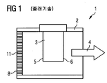
도 1은 종래 기술에 따른 공기 질량 유량계를 도시한다.
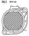
도 2는 그릴을 도시한다.
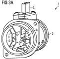
도 3a는 본 발명에 따른 공기 질량 유량계의 공기 입구측을 도시한다.
도 3b는 도 3a에 따른 공기 질량 유량계의 공기 출구측을 도시한다.
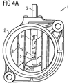
도 4a는 공기 입구측을 향해 본, 본 발명에 따른 공기 질량 유량계의 다른 실시 형태를 도시한다.
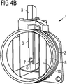
도 4b는 도 4a에 따른 공기 질량 유량계의 공기 출구측을 도시한다.
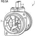
도 5a는 공기 입구측을 향해 본, 본 발명에 따른 공기 질량 유량계의 제3 실시 형태를 도시한다.
도 5b는 도 5a에 따른 공기 질량 유량계의 공기 출구측을 도시한다.
도 6a는 공기 입구측을 향해 본, 본 발명에 따른 공기 질량 유량계의 제4 실시 형태를 도시한다.
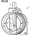
도 6b는 도 6a에 따른 공기 질량 유량계의 공기 출구측을 도시한다.The invention is explained in more detail below with reference to FIGS.
1 shows an air mass flow meter according to the prior art.
2 shows a grill.
3a shows the air inlet side of an air mass flow meter according to the invention.
3b shows the air outlet side of the air mass flow meter according to FIG. 3a.
4A shows another embodiment of an air mass flow meter in accordance with the present invention as viewed toward the air inlet side.
4b shows the air outlet side of the air mass flow meter according to FIG. 4a.
FIG. 5A shows a third embodiment of the air mass flow meter according to the present invention as viewed toward the air inlet side. FIG.
5b shows the air outlet side of the air mass flow meter according to FIG. 5a.
Fig. 6A shows a fourth embodiment of the air mass flow meter according to the present invention as viewed toward the air inlet side.
6b shows the air outlet side of the air mass flow meter according to FIG. 6a.
도 1은 종래 기술에 따른 공기 질량 유량계(1)를 도시한다. 공기 질량 유량계(1)는 관(2) 및 센서 모듈(3)을 포함한다. 센서 모듈(3)은 관(2) 내에서의 공기 질량체의 주 유동 방향에 대해 개시부(5) 및 종단부(6)를 구비한다. 관(2) 내에서의 공기 질량체의 모든 유속에서 오류 없이 측정을 수행할 수 있게 하기 위해서, 유동 지향 요소(8)가 센서 모듈(3)의 개시부(5)로부터 소정 거리를 두고 센서 모듈(3) 앞에 형성된다. 이 종래 기술 유동 지향 요소(8)는 그릴(11)로 구성된다.1 shows an air
도 2에, 이 그릴(11)이 정면도로 도시된다.In figure 2 this
도 3 내지 도 6에 예시된, 본 발명에 따른 공기 질량 센서는 그릴(11)로서 설계된 유동 지향 요소(8)를 완전히 배제한다.The air mass sensor according to the invention, illustrated in FIGS. 3 to 6, completely excludes the
도 3a는 본 발명에 따른 공기 질량 유량계(1)의 공기 입구측을 도시한다. 그것은 센서 모듈(3)이 내부에 위치되는 관(2)을 도시한다. 센서 모듈(3)은 소정 유속으로 관(2) 내에서 주 유동 방향(4)으로 유동하는 가스량을 측정하도록 설계된다.3a shows the air inlet side of an air
센서 모듈(3)은 관 내에서 주 유동 방향(4)으로 연장된다. 센서 모듈(3) 상에서 개시부(5)를 볼 수 있으며, 상기 개시부는 주 유동 방향(4)에 수직한 제1 평면을 규정한다.The
주 유동 방향(4)에 수직한 제2 평면이 도 3b에서 공기 질량 유량계(1)의 공기 출구측에 도시된다. 센서 모듈(3)은 관(2) 내에서 유동하는 가스량의 일부를 수용하는 그리고 상기 가스량을 측정 요소를 통해 지향시키는 유동 채널(7)을 구비한다. 긴 유동 지향 요소(8)가 공기 질량 유량계(1)의 관(2) 내에 배치되고, 주 유동 방향(4)에 평행하게 배향된다. 가스량은 유동 지향 요소(8)의 단부 면(9)을 향해 유동하고, 이어서 가스량은 유동 지향 요소의 벽 영역을 지나 유동한다. 유동 지향 요소(8)의 단부 면(9)은 관(2)의 단면을 감소시킨다. 그 결과, 센서 모듈(3)의 영역에서의 압력이 증가하고, 가스량의 유속이 상승된다. 가스량이 그것을 지나 유동하는 유동 지향 요소(8)의 벽 영역(10)은 가스량에 대향되게 놓인다. 지배적인 유속에 따라, 가스량의 층류 또는 난류가 상기 벽 영역(10)에 형성될 것이다. 유동 지향 요소(8)의 벽 영역(10)은 적어도 부분적으로 제1 및 제2 평면 사이에서 연장되며, 그 결과 관 내의 유속이 낮은 경우, 유동 지향 요소는 관 내의 유속에 대해, 센서 모듈의 영역에서 가스량의 유속을 증가시킨다. 그러나, 관 내의 가스량의 유속이 높은 경우, 유속은 센서 모듈(3)의 영역에서 보다 적게 증가되며, 이는 높은 유속에서 유동 지향 요소(8)의 벽 영역(10)에서의 난류의 개시에 기인한다. 유속이 낮은 경우, 유동 지향 요소(8)의 벽 영역(10)에 가스량의 층류가 존재하며, 그 결과 관(2) 내의 유속이 낮은 경우, 가스량의 유속은 관 내의 유속에 대해 센서 모듈(3)의 영역에서 증가된다.A second plane perpendicular to the
도 3b는 도 3a에 도시된 공기 질량 유량계(1)의 공기 출구측을 도시한다. 다시 한번, 센서 모듈(3)을 갖춘 관(2)을 볼 수 있다. 센서 모듈(3)은 이제 주 유동 방향(4)에 대해 그 종단부(6)를 도시한다. 센서 모듈(3)의 종단부(6)는 주 유동 방향(4)에 수직한 제2 평면을 형성한다. 또한, 벽 영역(10)을 갖춘 유동 지향 요소(8)를 볼 수 있다.FIG. 3B shows the air outlet side of the air
도 3a 및 도 3b에서, 유동 지향 요소(8)는 받침대(pedestal)-같은 물체로서 설계된다. 유동 지향 요소(8)는 관(2)과 일체로 형성될 수 있고, 사출 성형에 의해 제조될 수 있다.In FIGS. 3 a and 3b the
도 4a는 본 발명에 따른 공기 질량 유량계(1)의 공기 입구측을 도시한다. 센서 모듈(3)을 다시 한번 관(2) 내에서 볼 수 있다. 센서 모듈(3)은 주 유동 방향(4)에 대해 그 개시부(5)를 보여준다. 유동 채널(7)의 개시부를 또한 센서 모듈(3) 상에서 볼 수 있다. 유동 지향 요소(8)는 관(2) 내에 평행한 웨브로서 설계된다. 유동 지향 요소(8)의 단부 면(9)을 볼 수 있고, 유동 지향 요소(8)의 벽 영역(10)이 예시된다.4a shows the air inlet side of an air
도 4b는 도 4a에 예시된 공기 질량 유량계(1)의 공기 출구측을 도시한다. 센서 모듈(3)은 이제 주 유동 방향(4)에 대해 그 종단부(6)를 보여준다. 유동 지향 요소(8)의 형상을 다시 한번 볼 수 있다.FIG. 4B shows the air outlet side of the air
본 발명에 따른 공기 질량 유량계(1)가 또한 도 5a에 예시된다. 센서 모듈(3)을 다시 한번 관(2) 내에서 볼 수 있으며, 주 유동 방향(4)에 대해 그 개시부(5)를 보여준다. 유동 채널(7)이 센서 모듈(3) 상에 형성된다. 유동 지향 채널(8)은 이제 관(2) 내에 동심의, 부분적으로 중절된 원으로서 설계되고, 센서 모듈(3)에 평행하게 받침대-같은 방식으로 형성되는 유동 지향 요소(8)와 조합된다.An air
도 5b는 도 5a에 예시된 공기 질량 유량계(1)의 공기 출구측을 도시한다. 여기에서도, 유동 지향 요소(8)의 형상을 볼 수 있다. 관(2)에 대해 동심인 중절된 원이 유동 지향 요소(8)의 일부를 형성한다. 이와 조합되어, 도면은 센서 모듈(3)에 평행하게 배치되는 2개의 받침대-같은 유동 지향 요소를 보여준다.FIG. 5B shows the air outlet side of the air
본 발명에 따른 공기 질량 유량계(1)의 다른 실시 형태가 도 6a에 예시된다. 센서 모듈(3)은 다시 한번 관(2) 내에 배치된다. 유동 지향 요소(8)를 형성하는 두 웨브가 센서 모듈(3)에 평행하게 위치된다. 이들 웨브는 다른 유동 지향 요소(8)를 형성하는, 관과 동심인 원에 의해 보충된다.Another embodiment of an air
도 6b는 도 6a에 도시된 공기 질량 유량계의 공기 출구측을 도시한다. 여기에서도, 유동 지향 요소(8)의 형상이 예시된다. 본 발명에 따른 공기 질량 유량계(1)의 각각의 실시 형태에서, 유동 지향 요소(8)는 예컨대 사출 성형에 의해 관(2)과 일체형 구성요소로서 제조될 수 있다.FIG. 6B shows the air outlet side of the air mass flow meter shown in FIG. 6A. Here too, the shape of the
1: 공기 질량 유량계 2: 관
3: 센서 모듈 4: 주 유동 방향
5: 개시부 6: 종단부
7: 유동 채널 8: 유동 지향 요소
9: 단부 면 10: 벽 영역1: air mass flow meter 2: tube
3: sensor module 4: main flow direction
5: Initiation 6: Termination
7: flow channel 8: flow-oriented element
9: end face 10: wall area
Claims (6)
긴 유동 지향 요소(8)가 관(2) 내에 배치되고 주 유동 방향(4)에 평행하게 배향되어, 가스량이 유동 지향 요소(8)의 단부 면(9)을 향해 유동하고 유동 요소(8)의 벽 영역(10)을 지나 유동하며, 유동 지향 요소(8)의 벽 영역(10)은 적어도 부분적으로 제1 및 제2 평면 사이에서 연장되어, 관(2) 내의 유속이 낮은 경우, 유동 지향 요소(8)는 관(2) 내의 유속에 대해 센서 모듈(3)의 영역에서 가스량의 유속을 증가시키고, 관(2) 내의 가스량의 유속이 높은 경우, 유속에 대해 센서 모듈(3)의 영역에서 가스량의 유속을 보다 적게 증가시키는 것을 특징으로 하는 공기 질량 유량계(1).Air mass flow meter (1) consisting of a tube (2) and a sensor module (3) installed in the tube (2) for measuring the amount of gas flowing in the main flow direction (4) in the tube (2) at a predetermined flow rate As an example, the sensor module 3 extends in the tube 2 in the main flow direction 4, and defines a first plane in which the beginning 5 of the sensor module 3 is perpendicular to the main flow direction 4. The end 6 of the sensor module 3 defines a second plane perpendicular to the main flow direction 4, the sensor module 3 receiving a portion of the amount of gas flowing in the tube 2. And a flow channel (7) for directing the amount of gas through the measuring element,
An elongate flow directing element 8 is arranged in the tube 2 and is oriented parallel to the main flow direction 4 so that the amount of gas flows toward the end face 9 of the flow directing element 8 and the flow element 8. Flows past the wall region 10 of the flow directing element, the wall region 10 of the flow directing element 8 extends at least partially between the first and second planes, so that when the flow velocity in the tube 2 is low, flow directing The element 8 increases the flow rate of the gas amount in the region of the sensor module 3 with respect to the flow rate in the tube 2, and if the flow rate of the gas amount in the tube 2 is high, the region of the sensor module 3 relative to the flow rate. Air mass flow meter (1), characterized in that to increase the flow rate of the amount of gas at less.
유동 지향 요소(8)는 공기역학적인 설계를 갖는 것을 특징으로 하는 공기 질량 유량계(1).The method of claim 1,
Air mass flow meter (1), characterized in that the flow directing element (8) has an aerodynamic design.
유동 지향 요소(8)는 액적형 설계를 갖는 것을 특징으로 하는 공기 질량 유량계(1).The method of claim 2,
Air mass flow meter (1), characterized in that the flow directing element (8) has a droplet design.
유동 지향 요소(8)는 날개형 설계를 갖는 것을 특징으로 하는 공기 질량 유량계(1).The method of claim 2,
Air mass flow meter (1), characterized in that the flow directing element (8) has a vane design.
유동 지향 요소(8)는 관 단면을 10 - 50%만큼 감소시키는 것을 특징으로 하는 공기 질량 유량계(1).The method of claim 1,
Air mass flow meter (1), characterized in that the flow directing element (8) reduces the pipe cross section by 10-50%.
관(2)과 유동 지향 요소(8)는 일체형 구성요소로서 설계되는 것을 특징으로 하는 공기 질량 유량계(1).11. A method according to any one of the preceding claims,
Air mass flow meter (1), characterized in that the tube (2) and the flow directing element (8) are designed as an integral component.
Applications Claiming Priority (3)
| Application Number | Priority Date | Filing Date | Title |
|---|---|---|---|
| DE102010015523.3 | 2010-04-16 | ||
| DE102010015523A DE102010015523A1 (en) | 2010-04-16 | 2010-04-16 | Air flow sensor |
| PCT/EP2011/055656 WO2011128310A1 (en) | 2010-04-16 | 2011-04-12 | Air mass flowmeter |
Publications (1)
| Publication Number | Publication Date |
|---|---|
| KR20130092980A true KR20130092980A (en) | 2013-08-21 |
Family
ID=44170442
Family Applications (1)
| Application Number | Title | Priority Date | Filing Date |
|---|---|---|---|
| KR1020127029909A KR20130092980A (en) | 2010-04-16 | 2011-04-12 | Air mass flowmeter |
Country Status (7)
| Country | Link |
|---|---|
| US (1) | US8950272B2 (en) |
| EP (1) | EP2558825A1 (en) |
| JP (1) | JP2013525755A (en) |
| KR (1) | KR20130092980A (en) |
| CN (1) | CN102844645B (en) |
| DE (1) | DE102010015523A1 (en) |
| WO (1) | WO2011128310A1 (en) |
Families Citing this family (16)
| Publication number | Priority date | Publication date | Assignee | Title |
|---|---|---|---|---|
| DE102011056127B3 (en) * | 2011-12-07 | 2013-04-18 | Pierburg Gmbh | Device for determining gas mass flow in exhaust gas channel of internal combustion engine, has mass flow sensor whose sensing elements are arranged in honeycomb-shaped lattice portion |
| GB2539122B (en) | 2012-03-15 | 2017-03-15 | Fisher & Paykel Healthcare Ltd | Respiratory gas humidification system |
| GB2575894A (en) | 2012-04-27 | 2020-01-29 | Fisher & Paykel Healthcare Ltd | Usability features for respiratory humidification system |
| JP6140985B2 (en) * | 2012-11-19 | 2017-06-07 | トヨタ紡織株式会社 | Intake pipe structure of internal combustion engine |
| DE102013200344A1 (en) * | 2013-01-11 | 2014-07-17 | Robert Bosch Gmbh | Sensor arrangement for determining flow characteristic of fluid medium, particularly intake air mass of internal combustion engine, has wing grid which is arranged in main flow direction upstream of plug-in sensor |
| BR122017019835B1 (en) | 2013-09-13 | 2023-01-24 | Fisher & Paykel Healthcare Limited | HUMIDIFICATION SYSTEM AND ASSEMBLY METHOD OF A HUMIDIFICATION SYSTEM |
| CN103644948A (en) * | 2013-11-16 | 2014-03-19 | 中山欧麦克仪器设备有限公司 | Air mass flow meter |
| US10449319B2 (en) | 2014-02-07 | 2019-10-22 | Fisher & Paykel Healthcare Limited | Respiratory humidification system |
| EP3607988A1 (en) | 2014-06-03 | 2020-02-12 | Fisher & Paykel Healthcare Limited | Flow mixers for respiratory therapy systems |
| US10274195B2 (en) | 2016-08-31 | 2019-04-30 | Honeywell International Inc. | Air/gas admittance device for a combustion appliance |
| EP3551978B1 (en) | 2016-12-07 | 2022-01-26 | Fisher&Paykel Healthcare Limited | Sensing arrangements for medical devices |
| DE102018217779A1 (en) | 2018-10-17 | 2020-04-23 | Continental Automotive Gmbh | Air mass measuring device with flow guiding element |
| CN111220224B (en) * | 2018-11-26 | 2021-07-13 | 苏州原位芯片科技有限责任公司 | MEMS flow sensor chip |
| USD902255S1 (en) * | 2019-07-31 | 2020-11-17 | PRL Motorsports LLC | Intake system |
| CN112857499A (en) * | 2021-04-06 | 2021-05-28 | 浙江双良汽车零部件有限公司 | Air flow meter |
| CN114136647B (en) * | 2021-10-20 | 2023-10-03 | 中国航发四川燃气涡轮研究院 | Supersonic high-temperature three-dimensional flow field measuring device |
Family Cites Families (11)
| Publication number | Priority date | Publication date | Assignee | Title |
|---|---|---|---|---|
| EP0458998B1 (en) | 1990-05-30 | 1996-01-03 | Siemens Aktiengesellschaft | Current convertor |
| DE4340882A1 (en) | 1993-12-01 | 1995-06-08 | Bosch Gmbh Robert | Mass flowrate measuring device for i.c. engine air intake |
| JP3292817B2 (en) * | 1997-04-24 | 2002-06-17 | 三菱電機株式会社 | Thermal flow sensor |
| JP3285513B2 (en) | 1997-05-28 | 2002-05-27 | 三菱電機株式会社 | Thermal flow sensor and intake device for internal combustion engine |
| US6701781B1 (en) * | 2000-11-22 | 2004-03-09 | Visteon Global Technologies, Inc. | Mass air flow sensor bypass housing |
| DE10145195B4 (en) * | 2001-09-13 | 2005-10-06 | Siemens Ag | Device for measuring the air mass in an intake passage of an internal combustion engine |
| JP4177183B2 (en) | 2003-06-18 | 2008-11-05 | 株式会社日立製作所 | Thermal air flow meter |
| DE10337824B4 (en) * | 2003-08-18 | 2006-04-27 | Siemens Ag | Mass flow meter |
| DE102004028214A1 (en) * | 2004-06-09 | 2005-12-29 | Robert Bosch Gmbh | Flow measurement device, for measuring pressure, temperature or flow velocity in gas flow, has one or more sensors with upstream flow guidance plates that incorporate turbulence generators on their leading edges |
| JP4752472B2 (en) * | 2005-12-02 | 2011-08-17 | 株式会社デンソー | Air flow measurement device |
| DE102007026673A1 (en) * | 2007-06-08 | 2008-12-18 | Robert Bosch Gmbh | Device for regulating parameter of flowing medium in line in mainstream direction, particularly determination of air mass stream in sucking in tract of internal-combustion engine, has line part visual art of line passage |
-
2010
- 2010-04-16 DE DE102010015523A patent/DE102010015523A1/en not_active Ceased
-
2011
- 2011-04-12 JP JP2013504232A patent/JP2013525755A/en not_active Ceased
- 2011-04-12 KR KR1020127029909A patent/KR20130092980A/en not_active Application Discontinuation
- 2011-04-12 US US13/641,439 patent/US8950272B2/en not_active Expired - Fee Related
- 2011-04-12 CN CN201180018879.7A patent/CN102844645B/en not_active Expired - Fee Related
- 2011-04-12 WO PCT/EP2011/055656 patent/WO2011128310A1/en active Application Filing
- 2011-04-12 EP EP11713796A patent/EP2558825A1/en not_active Withdrawn
Also Published As
| Publication number | Publication date |
|---|---|
| US20130025353A1 (en) | 2013-01-31 |
| WO2011128310A1 (en) | 2011-10-20 |
| CN102844645B (en) | 2016-05-25 |
| CN102844645A (en) | 2012-12-26 |
| US8950272B2 (en) | 2015-02-10 |
| JP2013525755A (en) | 2013-06-20 |
| EP2558825A1 (en) | 2013-02-20 |
| DE102010015523A1 (en) | 2011-10-20 |
Similar Documents
| Publication | Publication Date | Title |
|---|---|---|
| KR20130092980A (en) | Air mass flowmeter | |
| US8752420B2 (en) | Sensor system for determining a parameter of a fluid medium | |
| JP5425902B2 (en) | Compound gas flow measuring method and apparatus | |
| US9217655B2 (en) | Sensor system for determining at least one flow property of a fluid medium flowing in a main flow direction | |
| JP5338864B2 (en) | Air flow measurement device | |
| US9453751B2 (en) | Fuel consumption measuring instrument | |
| EP0940657B1 (en) | Air flow meter | |
| JP2013525755A5 (en) | ||
| KR20010021842A (en) | Flowmeter | |
| JP2022084957A (en) | Physical quantity measuring device | |
| JP2018115997A (en) | Exhaust gas flow rate measurement unit and exhaust gas analysis device | |
| JP3848934B2 (en) | Air flow measurement device | |
| JP2003529757A (en) | Apparatus for measuring at least one parameter of a flowing medium | |
| CN104729604B (en) | Sensor assembly for determining at least one parameter of a fluid medium flowing through a channel | |
| JP2006522921A (en) | Apparatus for measuring at least one parameter of a medium flowing in a pipeline | |
| JP6134899B2 (en) | Flow measurement unit | |
| JP5816831B2 (en) | Ultrasonic flow meter | |
| WO2017073417A1 (en) | Thermal flowmeter | |
| JP4755712B2 (en) | Mass flow sensor device | |
| JP2007121036A (en) | Flowmeter | |
| US20160091356A1 (en) | Air flow meter | |
| JP2006118864A (en) | Gas meter | |
| US11215486B2 (en) | Pressure based flow sensor element having a pressure sensor and ribs positioned in the flow passage | |
| JP5015622B2 (en) | Flow rate measurement method | |
| CN108692774B (en) | Sensor element for sensing at least one property of a fluid medium |
Legal Events
| Date | Code | Title | Description |
|---|---|---|---|
| A201 | Request for examination | ||
| E601 | Decision to refuse application |