KR20130091623A - Disk-based storage device with head position control responsive to detected inter-track interference - Google Patents
Disk-based storage device with head position control responsive to detected inter-track interference Download PDFInfo
- Publication number
- KR20130091623A KR20130091623A KR1020120125139A KR20120125139A KR20130091623A KR 20130091623 A KR20130091623 A KR 20130091623A KR 1020120125139 A KR1020120125139 A KR 1020120125139A KR 20120125139 A KR20120125139 A KR 20120125139A KR 20130091623 A KR20130091623 A KR 20130091623A
- Authority
- KR
- South Korea
- Prior art keywords
- read
- write head
- servo
- storage disk
- head
- Prior art date
Links
Images


Classifications
-
- G—PHYSICS
- G11—INFORMATION STORAGE
- G11B—INFORMATION STORAGE BASED ON RELATIVE MOVEMENT BETWEEN RECORD CARRIER AND TRANSDUCER
- G11B5/00—Recording by magnetisation or demagnetisation of a record carrier; Reproducing by magnetic means; Record carriers therefor
- G11B5/48—Disposition or mounting of heads or head supports relative to record carriers ; arrangements of heads, e.g. for scanning the record carrier to increase the relative speed
- G11B5/56—Disposition or mounting of heads or head supports relative to record carriers ; arrangements of heads, e.g. for scanning the record carrier to increase the relative speed with provision for moving the head support for the purpose of adjusting the position of the head relative to the record carrier, e.g. manual adjustment for azimuth correction or track centering
-
- G—PHYSICS
- G11—INFORMATION STORAGE
- G11B—INFORMATION STORAGE BASED ON RELATIVE MOVEMENT BETWEEN RECORD CARRIER AND TRANSDUCER
- G11B5/00—Recording by magnetisation or demagnetisation of a record carrier; Reproducing by magnetic means; Record carriers therefor
- G11B5/48—Disposition or mounting of heads or head supports relative to record carriers ; arrangements of heads, e.g. for scanning the record carrier to increase the relative speed
- G11B5/58—Disposition or mounting of heads or head supports relative to record carriers ; arrangements of heads, e.g. for scanning the record carrier to increase the relative speed with provision for moving the head for the purpose of maintaining alignment of the head relative to the record carrier during transducing operation, e.g. to compensate for surface irregularities of the latter or for track following
- G11B5/596—Disposition or mounting of heads or head supports relative to record carriers ; arrangements of heads, e.g. for scanning the record carrier to increase the relative speed with provision for moving the head for the purpose of maintaining alignment of the head relative to the record carrier during transducing operation, e.g. to compensate for surface irregularities of the latter or for track following for track following on disks
- G11B5/59627—Aligning for runout, eccentricity or offset compensation
-
- G—PHYSICS
- G11—INFORMATION STORAGE
- G11B—INFORMATION STORAGE BASED ON RELATIVE MOVEMENT BETWEEN RECORD CARRIER AND TRANSDUCER
- G11B19/00—Driving, starting, stopping record carriers not specifically of filamentary or web form, or of supports therefor; Control thereof; Control of operating function ; Driving both disc and head
- G11B19/02—Control of operating function, e.g. switching from recording to reproducing
- G11B19/04—Arrangements for preventing, inhibiting, or warning against double recording on the same blank or against other recording or reproducing malfunctions
- G11B19/041—Detection or prevention of read or write errors
- G11B19/045—Detection or prevention of read or write errors by detecting mistracking
-
- G—PHYSICS
- G11—INFORMATION STORAGE
- G11B—INFORMATION STORAGE BASED ON RELATIVE MOVEMENT BETWEEN RECORD CARRIER AND TRANSDUCER
- G11B21/00—Head arrangements not specific to the method of recording or reproducing
- G11B21/02—Driving or moving of heads
Abstract
Description
HDD(hard disk drive)와 같은 디스크 기반 저장 디바이스는 매우 다양한 상이한 유형의 데이터 처리 시스템들에서 비휘발성 데이터 저장소를 제공하는데 이용된다. 전형적인 HDD는 플래터(platter) 라고도 지칭되는 하나 이상의 편평한 원형 저장 디스크들을 보유하는 스핀들(spindle)을 포함한다. 각각의 저장 디스크는 하나 이상의 자기 재료 박층들로 코팅되는 알루미늄 또는 유리와 같은 비자성 재료로 제조되는 기판을 포함한다. 동작시에, 디스크가 고속으로 회전함에 따라 포지셔닝 암(positioning arm)에 의해 디스크 표면을 가로질러 정밀하게 이동되는 판독/기록 헤드를 통해, 데이터가 저장 디스크의 트랙들로부터 판독 및 트랙들에 기록된다.Disk-based storage devices such as hard disk drives (HDDs) are used to provide nonvolatile data storage in a wide variety of different types of data processing systems. A typical HDD includes a spindle that holds one or more flat circular storage disks, also called platters. Each storage disk includes a substrate made of a nonmagnetic material such as aluminum or glass that is coated with one or more layers of magnetic material. In operation, data is written to and read from the tracks of the storage disc via a read / write head that is precisely moved across the disc surface by a positioning arm as the disc rotates at high speed. .
전형적으로, 종래의 HDD들은, 일반적으로 "서보(servo)" 마크들 이라고 지칭되는 위치 에러 검출 필드들이 저장 디스크 상의 고정된 간격들로 기록되는 판독/기록 헤드 위치 제어 시스템을 이용한다. 이러한 서보 마크들은, 서보 기록기를 이용하여, 드라이브 제조시에 단지 1회 기록된다. 예로써, 웨지 서보 배열(wedge servo arrangement)에서, 디스크 주위에 분포된 지정된 방사상 웨지들에 서보 마크들이 형성된다. 서보 웨지들 사이의 데이터 웨지들은 다수의 데이터 섹터들을 포함하고, 트랙 용량(capacity)의 대부분을 소비한다. 서보 알고리즘은 서보 웨지들로부터의 서보 마크들을 이용하여 헤드 위치를 검출한다. 데이터 웨지 동안 어떠한 위치 피드백도 이용가능하지 않으므로, 전형적으로 서보 알고리즘은 검출된 서보 마크들 사이의 헤드 위치를 보간(interpolate)해야 한다. 서보 마크들의 다른 배열도 또한 가능하다. 예를 들어, 서보 마크들은 서보 웨지들 내로 구성되기보다는, 디스크 전체를 통해 고르게 분포될 수 있다.Typically, conventional HDDs use a read / write head position control system in which position error detection fields, generally referred to as "servo" marks, are recorded at fixed intervals on the storage disk. These servo marks are written only once at drive manufacture, using a servo recorder. By way of example, in a wedge servo arrangement, servo marks are formed in designated radial wedges distributed around the disk. Data wedges between servo wedges contain multiple data sectors and consume most of the track capacity. The servo algorithm detects head position using servo marks from servo wedges. Since no position feedback is available during the data wedge, typically the servo algorithm must interpolate the head position between the detected servo marks. Other arrangements of servo marks are also possible. For example, the servo marks may be evenly distributed throughout the disc, rather than being organized into servo wedges.
HDD 동작 동안, 드라이브 하드웨어는 서보 마크들을 판독하여 판독/기록 헤드 위치 에러의 추정을 계산하며, 그것은 판독/기록 헤드의 방사상 위치를 유지하기 위해 펌웨어 제어 루프에서 이용된다. 서보 마크들에 대해 전용된 디스크 공간은 사용자 데이터를 저장하는데 이용될 수 없기 때문에, 디스크 상에 기록된 서보 마크들의 수는 판독/기록 헤드 위치 제어 루프의 대역폭과 드라이브의 용량 사이의 트레이드오프(tradeoff)를 정의한다.During HDD operation, the drive hardware reads the servo marks to calculate an estimate of the read / write head position error, which is used in the firmware control loop to maintain the radial position of the read / write head. Since the disk space dedicated for the servo marks cannot be used to store user data, the number of servo marks recorded on the disk is a tradeoff between the bandwidth of the read / write head position control loop and the capacity of the drive. ).
HDD들의 저장 용량은 계속해서 증가하며, 수 테라바이트(terabytes; TB)의 데이터를 저장할 수있는 HDD들이 현재 이용가능하다. 그러나, 때때로 저장 용량의 증가는 보다 많은 트랙들을 각각의 저장 디스크 상에 맞추기 위한 트랙 치수 감소를 수반하여, 트랙간 간섭(inter-track interference; ITI) 및 판독/기록 헤드 위치가 중요한 성능 제한 문제로 되고 있다. 또한, 판독/기록 헤드 스케일링이 제한되어, 하나의 트랙을 기록하는데 이용된 자기장이 결국은 인접한 트랙들에 영향을 미치고, 그로 인해 트랙 밀도를 제한할 것이다.The storage capacity of HDDs continues to increase, and HDDs capable of storing several terabytes (TB) of data are now available. However, sometimes the increase in storage capacity is accompanied by a reduction in track dimensions to fit more tracks on each storage disk, so inter-track interference (ITI) and read / write head position are important performance limitation issues. It is becoming. In addition, read / write head scaling is limited so that the magnetic field used to record one track will eventually affect adjacent tracks, thereby limiting the track density.
HDD 저장 용량을 더 증가시키기 위한 노력으로, 다수의 레코딩 기술들이 개발되어 왔다. 예를 들어, SMR(shingled magnetic recording)로서 알려진 레코딩 기술은 저장 디스크 상의 이전에 기록된 인접 트랙을 통해 주어진 트랙을 "싱글링(shingling)"함으로써 HDD의 저장 용량을 증가시키고자 시도한다. BPM(bit-patterned madia)으로서 지칭되는 다른 레코딩 기술에서, 자기 아일랜드(magnetic island)들의 고밀도 트랙들이 저장 디스크의 표면 상에서 수행되고, 데이터의 비트들이 이러한 아일랜드들 각각에 기록된다. 그럼에도 불구하고, ITI 및 판독/기록 헤드 위치는, 이들 및 다른 HDD 레코딩 기술들을 이용하여 중요한 성능 제한 문제들로 남아 있다.In an effort to further increase HDD storage capacity, a number of recording technologies have been developed. For example, a recording technique known as shredled magnetic recording (SMR) attempts to increase the storage capacity of the HDD by "shingling" a given track through previously recorded adjacent tracks on the storage disk. In another recording technique called bit-patterned madia (BPM), high density tracks of magnetic islands are performed on the surface of the storage disk, and bits of data are recorded on each of these islands. Nevertheless, ITI and read / write head positions remain significant performance limitation issues using these and other HDD recording techniques.
HDD 성능에 대한 ITI의 악영향은, 일부 경우에 있어서, 판독시에 ITI 소거 기술들의 적용을 통해 해결될 수 있다. 그러한 소거 기술들은, 예를 들면, 저장 디스크로부터 판독된 데이터에 대해 ITI 감소 후처리를 수행하는 것을 포함할 수 있다. 이러한 유형의 기술에서, 인접 트랙 상에 저장된 간섭하는 데이터 패턴에 관한 정보를 이용하여, ITI 유도 판독 신호 잡음을 검출하고, 통상적인 데이터 복원 처리가 적용되기 전에 판독 신호로부터의 그러한 잡음을 소거한다. 그러나, 전형적으로 감소 후처리는, 간섭하는 데이터가 저장 디스크로부터 판독되어 메모리에 저장될 것을 요구하며, 그것은 HDD 비용 및 복잡도를 증가시키고, 또한 액세스 시간과 같은 다른 성능 척도들에 악영향을 미치게 된다.The adverse effect of ITI on HDD performance can be addressed in some cases through the application of ITI erase techniques at read time. Such erasure techniques may include, for example, performing ITI reduction post-processing on data read from the storage disk. In this type of technique, information about interfering data patterns stored on adjacent tracks is used to detect ITI induced read signal noise and cancel such noise from the read signal before conventional data recovery processing is applied. Typically, however, reduced post-processing requires interfering data to be read from the storage disk and stored in memory, which increases HDD cost and complexity, and also adversely affects other performance measures such as access time.
또한, 인접한 비트 극성들을 고려하는 방식으로 기록 신호의 보상 전처리에 의해 ITI를 감소시킬 수 있다. 이러한 유형의 기록 보상 기술들은 본 출원과 공동으로 양도되고 본 명세서에서 참조로 인용되는, 2011년 9월 30일에 "Disk-Based Storage Device having Write Signal Compensation for Magnetization Polarity of Adjacent Bits" 라는 제목으로 출원된 미국 특허 출원 제 13/250,419 호에 개시되어 있다.
It is also possible to reduce the ITI by compensation preprocessing of the write signal in a manner that takes into account adjacent bit polarities. This type of write compensation technology is filed on September 30, 2011, titled “Disk-Based Storage Device having Write Signal Compensation for Magnetization Polarity of Adjacent Bits”, which is jointly assigned with the present application and incorporated herein by reference. No. 13 / 250,419, which is incorporated herein by reference.
본 발명의 예시적인 실시예들은, 검출된 ITI에 적어도 부분적으로 기초하여 헤드 위치를 제어함으로써 강화된 동작 성능을 나타내는 HDD들 또는 다른 유형의 디스크 기반 저장 디바이스들을 제공한다. 예를 들어, 그러한 실시예에 따른 HDD는 ITI 소거 프로세스 또는 다른 것의 일부로서 ITI를 검출하고, 검출된 ITI에 관한 정보를, 검출된 ITI에 응답하여 헤드 위치를 조정하는 헤드 위치 제어기에 제공할 수 있다.Exemplary embodiments of the present invention provide HDDs or other types of disk based storage devices that exhibit enhanced operational performance by controlling head position based at least in part on the detected ITI. For example, an HDD according to such an embodiment may detect an ITI as part of an ITI erase process or others, and provide information about the detected ITI to a head position controller that adjusts the head position in response to the detected ITI. have.
하나 이상의 실시예에서의 ITI 기반 헤드 위치 제어는 종래의 서보 기반 헤드 위치 제어와 함께 또는 그것을 대신하여 이용될 수 있다. 헤드 위치 제어를 위해 ITI를 이용하는 것은, ITI 피드백이 거의 항상 이용가능하는 점에서 특히 이로운 것이며, 반면에 서보 피드백은 서보 마크들이 저장 디스크 상에서 정규 간격으로 처리될 때에만 일반적으로 이용가능하다.ITI based head position control in one or more embodiments may be used in conjunction with or instead of conventional servo based head position control. Using ITI for head position control is particularly advantageous in that ITI feedback is almost always available, while servo feedback is generally only available when servo marks are processed at regular intervals on the storage disk.
일 실시예에서, HDD 또는 다른 디스크 기반 저장 디바이스는 저장 디스크, 저장 디스크로부터 데이터를 판독 및 저장 디스크로 데이터를 기록하도록 구성된 판독/기록 헤드, 및 판독/기록 헤드에 연결되어 판독/기록 헤드로부터 수신 및 판독/기록 헤드에 공급된 데이터를 처리하도록 구성되며, 저장 디스크에 대한 판독/기록 헤드의 포지셔닝을 제어하는 제어 회로를 포함한다. 이러한 실시예에서, 제어 회로는 판독/기록 헤드를 통해 저장 디스크의 적어도 주어진 트랙으로부터 판독된 신호를 처리하여, 저장 디스크의 적어도 하나의 다른 트랙으로부터의 해당 신호에서의 ITI를 검출하도록 구성된 ITI 검출기를 포함한다. 제어 회로는 검출된 ITI에 응답하여 판독/기록 헤드의 포지셔닝을 조정하도록 구성된 ITI 기반 헤드 위치 제어기를 더 포함한다.In one embodiment, an HDD or other disk based storage device reads from a storage disk, a read / write head configured to read data from and write data to the storage disk, and is connected to the read / write head to receive from the read / write head. And a control circuit configured to process data supplied to the read / write head, the control circuit controlling the positioning of the read / write head relative to the storage disk. In such an embodiment, the control circuit is configured to process a signal read from at least a given track of the storage disk via a read / write head to detect an ITI detector at that signal from at least one other track of the storage disk. Include. The control circuit further includes an ITI based head position controller configured to adjust the positioning of the read / write head in response to the detected ITI.
ITI 기반 헤드 위치 제어기는, 저장 디스크의 표면 상의 서보 마크들의 타이밍 패턴을 검출함으로써 서보 타이밍 정보를 생성하는 서보 제어기의 일부이거나, 또는 서보 제어기와 함께 동작하도록 구성될 수 있다. 예를 들어, 서보 제어기는 헤드 위치 제어기를 포함할 수 있으며, 서보 타이밍 정보 및 검출된 ITI를 특성화하는 정보 둘다를 이용하여 판독/기록 헤드의 포지셔닝을 제어하도록 구성될 수 있다. 그러나, 전술한 바와 같이, ITI 기반 헤드 위치 제어는 서보 제어의 이용을 요구하지 않는다.The ITI based head position controller may be part of a servo controller that generates servo timing information by detecting timing patterns of servo marks on the surface of the storage disk, or may be configured to operate with the servo controller. For example, the servo controller may include a head position controller and may be configured to control the positioning of the read / write head using both servo timing information and information characterizing the detected ITI. However, as mentioned above, ITI based head position control does not require the use of servo control.
본 발명의 하나 이상의 실시예는 디스크 기반 저장 디바이스들에서의 큰 향상을 제공한다. 예를 들어, 검출된 ITI에 적어도 부분적으로 기초하여 헤드 위치를 조정함으로써, 헤드 위치는 ITI의 존재시에 데이터 복원을 위해 최적화될 수 있다. 이것은 종래의 서보 제어를 이용하거나 또는 이용하지 않고서, 헤드 위치 정확성이 향상되도록 함으로써, 낮은 비용으로 보다 우수한 성능을 제공한다. 더욱이, 그러한 구성은 트랙 피치(track pitch)가 감소되도록 함으로써, 주어진 저장 디스크에 대해 증가된 저장 용량을 제공한다.
One or more embodiments of the present invention provide a significant improvement in disk based storage devices. For example, by adjusting the head position based at least in part on the detected ITI, the head position can be optimized for data recovery in the presence of the ITI. This allows better head position accuracy, with or without conventional servo control, thereby providing better performance at lower cost. Moreover, such a configuration allows the track pitch to be reduced, thereby providing increased storage capacity for a given storage disk.
도 1은 본 발명의 예시적인 실시예에 따른 디스크 기반 저장 디바이스의 투시도를 도시한다.
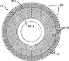
도 2는 도 1의 저장 디바이스에서의 저장 디스크의 평면도를 도시한다.
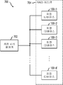
도 3은 디스크 제어기 및 판독 채널 회로를 포함하는 예시적인 시스템-온-칩을 포함하는 도 1의 저장 디바이스의 일부의 블록도이다.
도 4는 도 1의 저장 디바이스의 일부의 다른 도면을 도시한다.
도 5a 및 도 5b는 본 발명의 실시예들에서의 판독/기록 헤드 오프셋의 함수로서 ITI에서의 변동들을 도시한다.
도 6은 데이터 처리 시스템에서의 호스트 처리 디바이스와 도 1의 저장 디바이스의 상호접속을 도시한다.
도 7은 도 1에 도시된 유형의 복수의 디스크 기반 저장 디바이스들을 포함하는 가상 저장 시스템을 도시한다.1 illustrates a perspective view of a disk based storage device in accordance with an exemplary embodiment of the present invention.
FIG. 2 shows a top view of a storage disk in the storage device of FIG. 1.
3 is a block diagram of a portion of the storage device of FIG. 1 including an exemplary system-on-chip including a disk controller and read channel circuitry.
4 shows another view of a portion of the storage device of FIG. 1.
5A and 5B show variations in ITI as a function of read / write head offset in embodiments of the present invention.
6 illustrates an interconnection of a host processing device and a storage device of FIG. 1 in a data processing system.
FIG. 7 illustrates a virtual storage system including a plurality of disk based storage devices of the type shown in FIG. 1.
본 명세서에서, 본 발명의 실시예들은 예시적인 디스크 기반 저장 디바이스들, 제어 회로 및 관련된 ITI 기반 헤드 위치 제어 기술들과 함께 기술될 것이다. 그러나, 본 발명의 이들 및 다른 실시예들이, 정확하고 효율적인 헤드 위치 제어의 관점에서 향상된 성능이 요망되는 임의의 디스크 기반 저장 디바이스에 보다 일반적으로 적용가능함을 이해해야 한다. 예시된 실시예들과 함께 구체적으로 도시 및 기술된 것들 이외의 구성요소들을 이용하여 추가적인 실시예들이 구현될 수 있다.In the present specification, embodiments of the present invention will be described in conjunction with exemplary disk based storage devices, control circuitry and related ITI based head position control techniques. However, it should be understood that these and other embodiments of the present invention are more generally applicable to any disk based storage device where improved performance is desired in view of accurate and efficient head position control. Additional embodiments may be implemented using components other than those specifically shown and described with the illustrated embodiments.
도 1은 본 발명의 예시적인 실시예에 따른 디스크 기반 저장 디바이스(100)를 도시한다. 이러한 실시예에서의 저장 디바이스(100)는, 보다 구체적으로, 저장 디스크(110)를 포함하는 HDD를 포함한다. 저장 디스크(110)는 자화 상태(magnetization state)들의 형태로 데이터를 저장할 수 있는 하나 이상의 자기 재료들로 코팅된 저장 표면을 갖는다. 저장 디스크(110)는 스핀들(spindle)(120)에 접속된다. 도면에서 명시적으로 도시되지는 않았지만, 스핀들(120)은 스핀들 모터에 의해 구동되어, 저장 디스크(110)를 고속으로 회전시킨다.1 illustrates a disk based
포지셔닝 암(140) 상에 탑재되는 판독/기록 헤드(130)를 통해 데이터가 저장 디스크(110)로부터 판독 및 저장 디스크(110)에 기록된다. 저장 디스크(110)의 자기 표면에 걸친 판독/기록 헤드의 위치는 전자기 액츄에이터(electromagnetic actuator)(150)에 의해 제어된다. 본 실시예에서의 전자기 액츄에이터(150) 및 그것의 관련된 드라이버 회로는, 본 명세서에서 저장 디바이스(100)의 "제어 회로"로서 보다 일반적으로 지칭되는 것의 일부를 포함하는 것으로 보여질 수 있다. 이러한 실시예에서의 그러한 제어 회로는 어셈블리의 반대면 상에 배열되고, 그에 따라 도 1의 투시도에서 보이지 않는 추가적인 전자 구성요소들을 더 포함하는 것으로 가정된다. 따라서, 본 명세서에서 이용된 "제어 회로" 라는 용어는, 예시적인 것일 뿐 제한적인 것이 아닌, 드라이브 전자장치, 신호 처리 전자장치 및 관련된 처리 및 메모리 회로를 포함하는 것으로 넓리 이해되도록 의도되며, 저장 디바이스에서의 저장 디스크의 저장 표면에 대한 판독/기록 헤드의 포지셔닝을 제어하는데 이용되는 다른 요소들을 더 포함할 수 있다. 접속기(160)를 이용하여 저장 디바이스(100)를 호스트 컴퓨터 또는 다른 관련 처리 디바이스에 접속한다.Data is written from the
도 1은 단일의 저장 디스크(110), 판독/기록 헤드(130) 및 포지셔닝 암(140) 각각의 단지 하나의 경우만을 갖는 본 발명의 실시예를 도시하지만, 이것은 단지 예시적인 예일 뿐이며, 본 발명의 대안적인 실시예들은 이들 및 다른 드라이브 구성요소들의 하나 이상의 다수의 경우들을 포함할 수 있음을 이해할 것이다. 예를 들어, 하나의 그러한 예시적인 실시예는 동일한 스핀들에 부착된 다수의 저장 디스크들을 포함하여, 그러한 디스크들 모두가 동일한 속도로 회전하고, 다수의 판독/기록 헤드들 및 관련된 포지셔닝 암들은 하나 이상의 액츄에이터들에 연결될 수 있다. 본 명세서에서 널리 이용되는 용어로서의 주어진 판독/기록 헤드는 분리된 판독 및 기록 헤드들의 조합의 형태로 구현될 수 있다. 특히, 본 명세서에서 이용된 "판독/기록" 이라는 용어는, 판독/기록 헤드가 판독 헤드 전용, 기록 헤드 전용, 판독 및 기록 둘다를 위해 이용된 하나의 헤드, 또는 분리된 판독 및 기록 헤드들의 조합을 포함할 수 있도록, 판독 및/또는 기록으로서 넓게 이해되는 것을 의도한다.1 illustrates an embodiment of the present invention having only one case of each of a
또한, 도 1에 도시된 바와 같은 저장 디바이스(100)는, 그러한 저장 디바이스의 종래의 구현에서 일반적으로 발견되는 유형의 하나 이상의 요소들을 포함하여, 구체적으로 도시된 것들에 추가하여 또는 그것들 대신에 다른 요소들을 포함할 수 있다. 본 기술 분야의 당업자에 의해 잘 이해되는 이들 및 다른 종래의 요소들은 본 명세서에서 상세하게 기술되지 않는다. 또한, 도 1에 도시된 요소들의 특정한 배열은 단지 예시적인 예로써 제공됨을 이해해야 한다. 개시된 기술들은 저장 디바이스 내에 향상된 헤드 위치 제어를 제공하는 것이 바람직한 임의의 저장 디바이스 응용에 대해 제한없이 보다 일반적으로 적용가능하다. 따라서, 본 기술 분야의 당업자라면, 본 발명의 실시예들을 구현시에 매우 다양한 다른 저장 디바이스 구성들이 이용될 수 있음을 인식할 것이다.In addition, the
도 2는 저장 디스크(110)의 저장 표면을 보다 상세히 도시한다. 도시된 바와 같이, 저장 디스크(110)의 저장 표면은 복수의 동심 트랙들(concentric tracks)(210)을 포함한다. 각각의 트랙은 차후의 검색을 위한 데이터의 블록을 저장할 수 있는 복수의 섹터들(220)로 세분된다. 저장 디스크의 바깥쪽 에지 쪽으로 위치된 트랙들은, 저장 디스크의 중심 쪽으로 위치된 트랙들과 비교했을 때, 보다 큰 둘레를 갖는다. 트랙들은 수 개의 환형 구역들(annular zones)(230)로 그룹화되고, 구역들 중 주어진 하나의 구역 내의 트랙들은 동일한 수의 섹터를 갖는다. 바깥쪽 구역들에 있는 트랙들은 안쪽 구역들에 위치된 트랙들보다 많은 섹터들을 갖는다. 이러한 예에서, 저장 디스크(110)는 가장 바깥쪽 구역(230-0) 및 가장 안쪽 구역(230-M)을 포함하는 M+1 구역들을 포함하는 것으로 가정한다.2 shows the storage surface of the
저장 디스크(110)의 바깥쪽 구역들은 안쪽 구역들보다 높은 데이터 전송 레이트를 제공한다. 이것은, 본 실시예에서의 저장 디스크는, 일단 동작 속도로 회전되도록 가속되면, 판독/기록 헤드의 포지셔닝에 관계없이 일정한 각속도(angular speed) 또는 시선 속도(radial speed)로 회전하지만, 안쪽 구역들의 트랙들은 바깥쪽 구역들의 트랙들보다 작은 둘레를 갖는다는 사실에 부분적으로 기인한다. 따라서, 판독/기록 헤드가 바깥쪽 구역의 트랙들 중 하나에 걸쳐 포지셔닝될 때, 그것은 안쪽 구역의 트랙들 중 하나에 걸쳐 포지셔닝될 때보다 저장 디스크의 주어진 360° 턴에 대해 디스크 표면을 따라 보다 큰 선형 거리를 커버한다. 그러한 배열은 저장 디스크의 각각의 360° 턴이 동일한 양의 시간을 취하기 때문에, 일정한 각속도(constant angular velocity; CAV)를 갖는 것으로 지칭되지만, CAV 동작은 본 발명의 실시예들의 요건은 아님을 이해해야 한다.The outer sections of the
일반적으로, 데이터 비트 밀도는 저장 디스크(110)의 전체 저장 표면을 통해 일정하며, 그것은 바깥쪽 구역들에서 보다 높은 데이터 전송 레이트들을 초래한다. 각각의 바깥쪽 구역은 안쪽 구역들보다 많은 데이터를 저장하기 때문에, 판독/기록 헤드는 바깥쪽 구역들에서의 데이터에 액세스할 때에 주어진 데이터의 양을 판독하기 위해 빈번하게 이동할 필요가 없다. 따라서, 데이터는 안쪽 구역들에서의 트랙들로 또는 트랙들로부터의 레이트보다 바깥쪽 구역들에서의 트랙들로 또는 트랙들로부터 보다 높은 레이트에서 전송될 수 있다.In general, the data bit density is constant throughout the entire storage surface of the
따라서, 저장 디스크의 가장 바깥쪽 환상 구역(230-0)은 저장 디스크의 가장 안쪽 환상 구역(230-M)보다 높은 평균 데이터 전송 레이트를 갖는다. 평균 데이터 전송 레이트들은 주어진 실시예에서 가장 안쪽 환상 구역과 가장 바깥쪽 환상 구역 사이에서, 2배(a factor of two)보다 많은 만큼 상이할 수 있다.Thus, the outermost annular region 230-0 of the storage disk has a higher average data transfer rate than the innermost annular region 230-M of the storage disk. Average data transfer rates may differ by more than a factor of two between the innermost annular zone and the outermost annular zone in a given embodiment.
단지 예시를 위해 제공된 하나의 예시적인 실시예로서, 가장 바깥쪽 환상 구역은 약 2.3 Gb/s(Gigabits per second)의 데이터 전송 레이트를 가질 수 있으며, 가장 안쪽 환상 구역은 약 1.0 Gb/s의 데이터 전송 레이트를 갖는다. 그러한 구현에서, HDD는 특히, 500 GB의 총 저장 용량 및 7200 RPM의 스핀들 속도를 가질 수 있으며, 전술한 바와 같이, 데이터 전송 레이트들은 가장 바깥쪽 구역에 대한 약 2.3 Gb/s로부터 가장 안쪽 구역에 대한 약 1.0 Gb/s 까지의 범위를 갖는다.As one exemplary embodiment provided for illustrative purposes only, the outermost annular zone may have a data transfer rate of about 2.3 Gb / s (seconds), and the innermost annular zone is about 1.0 Gb / s of data. Has a transmission rate. In such implementations, the HDD may in particular have a total storage capacity of 500 GB and a spindle speed of 7200 RPM, and as described above, the data transfer rates may range from about 2.3 Gb / s to the innermost zone for the outermost zone. For up to about 1.0 Gb / s.
또한, 저장 디스크(110)는 그것의 저장 표면 상에 형성된 타이밍 패턴을 포함하는 것으로 가정된다. 그러한 타이밍 패턴은 서보 어드레스 마크(servo address mark; SAM)들의 하나 이상의 세트들, 또는 종래의 방식으로 특정 섹터들에 형성된 다른 유형의 서보 마크들을 포함할 수 있다. 따라서, SAM은 본 명세서에서 서보 마크들로서 보다 구체적으로 지칭되는 것의 일례로서 보여질 수 있다. 따라서, 본 명세서에서 이용된 "타이밍 패턴" 이라는 용어는 다수의 서보 마크들의 배열을 포함하도록 의도된다.In addition, it is assumed that
저장 디바이스(100)는, 저장 디스크(110)의 표면 상의 서보 타이밍 패턴과 내부 판독 채널 클록 사이의 주파수 및 위상 차이를 감소시키기 위해 DLC(disk locked clock) 기법을 구현할 수 있다. 이것은 데이터 섹터들이 보다 작은 주파수 변동으로 기록될 수 있도록 허용함으로써, 데이터 섹터들이 판독될 때, 판독 채널에서의 클록 복원 루프(clock recovery loop)가 많은 주파수 변동을 처리하지 않아도 되도록 한다. 전형적인 DLC 기법은, 예를 들면, 저장 디스크의 표면 상의 타이밍 패턴을 제공하는 서보 마크들의 위치 및 위상을 측정하는 것을 포함할 수 있다. HDD 또는 다른 디스크 기반 저장 디바이스에서의 서보 마크들의 측정에 관한 추가적인 세부사항들은, 본 출원과 공동으로 양도되고 본 명세서에서 참조로 인용되는, “Methods and Apparatus for Measuring Servo Address Mark Distance in a Read Channel Using Selective Fine Phase Estimate” 라는 제목의 미국 특허 제 8,049,982 호에서 찾을 수 있다.The
전술한 실시예에서 언급된 특정한 데이터 전송 레이트들 및 다른 특징들은 단지 예시를 위한 것이며, 어떠한 방식으로든 제한하는 것으로서 이해되어서는 않된다. 매우 다양한 다른 데이터 전송 레이트들 및 저장 디스크 구성들이 다른 실시예들에서 이용될 수 있다.The specific data transfer rates and other features mentioned in the above embodiments are for illustration only and should not be understood as limiting in any way. A wide variety of other data transfer rates and storage disk configurations may be used in other embodiments.
본 발명의 실시예들이 도 3 내지 도 5와 함께 후술될 것이며, 여기서 도 1의 저장 디바이스(100)는 ITI 기반 헤드 위치 제어를 위한 프로세스를 구현하도록 구성된다. 이러한 실시예들에 있어서는, ITI 기반 헤드 위치 제어가 종래의 서보 기반 헤드 위치 제어와 함께 이용되지만, 다른 실시예들은 서보 기반 헤드 위치 제어를 이용하지 않고서 ITI 기반 헤드 위치 제어를 구현할 수 있다.Embodiments of the present invention will be described below in conjunction with FIGS. 3-5, wherein the
도 3은 도 1의 저장 디바이스(100)의 일부분을 보다 상세히 도시한다. 이러한 도면에서, 저장 디바이스(100)는 버스(306)를 통해 통신하는 프로세서(300), 메모리(302) 및 SOC(system-on-a-chip)(304)를 포함한다. 저장 디바이스는 SOC(304)와 판독/기록 헤드(130) 사이에 인터페이스를 제공하는 드라이버 회로(305)를 더 포함한다. 드라이버 회로(305)는, 예를 들면, 전치증폭기 및 다른 관련된 인터페이스 회로를 포함할 수 있다. 메모리(302)는 저장 디바이스(100)의 SOC(304) 및 다른 구성요소들에 대한 외부의 메모리이지만, 그럼에도 불구하고, 저장 디바이스에 대해 내부에 존재한다. 판독/기록 헤드(130) 및 저장 디스크(110)는, 도 3에서 헤드 디스크 어셈블리(head disk assembly; HDA)(308)를 포함하는 것으로서 집합적으로 표시된다.3 illustrates a portion of the
본 실시예에서의 SOC(304)는 판독 채널 회로(310) 및 디스크 제어기(312)를 포함하며, 저장 디스크(110)로부터의 데이터 판독시에 및 저장 디스크(110)로의 데이터 기록시에, 판독/기록 헤드(130)의 동작을 지시한다. 판독 채널 회로(310) 및 디스크 제어기(312)는 버스(306)의 일부분을 나타내는 것으로서 보여질 수 있는 하나 이상의 인터페이스 접속들(314)을 통해 서로 통신한다.The
버스(306)는, 예를 들면, 하나 이상의 상호접속 패브릭(interconnect fabric)들을 포함할 수 있다. 그러한 패브릭은 본 실시예에서 AXI(Advanced eXtensible Interface) 패브릭으로서 구현될 수 있으며, AXI 패브릭은 예를 들면, 본 명세서에서 참조로 인용되는 AMBA(Advanced Microcontroller Bus Architecture) AXI v2.0 사양에 보다 상세히 기술되어 있다. 또한, 버스는 SOC(304)와 드라이버 회로(305) 사이와 같은, 다른 시스템 구성요소들 사이의 통신들을 지원하는데 이용될 수 있다. AXI 상호접속들이 요구되는 것은 아니며, 매우 다양한 다른 유형의 버스 구성들이 본 발명의 실시예들에서 이용될 수 있음을 이해해야 한다.The
디스크 제어기(312)는 판독 채널 회로(310)에서 구현된 ITI 검출기(320)로부터의 검출된 ITI에 응답하는 헤드 위치 제어기(315)를 포함한다. 헤드 위치 제어기(315)는 또한, 서보 회로(322)에 의해 제공된 서보 타이밍 정보에도 응답한다. 일반적으로, ITI 검출기(320)는 판독/기록 헤드(130)를 통해 저장 디스크(110)의 적어도 주어진 트랙으로부터 판독된 신호를 처리하여, 저장 디스크의 적어도 하나의 트랙으로부터의 해당 신호에서의 간섭을 검출하도록 구성된다. 본 실시예에서, ITI 검출기(320)에 의해 처리된 신호가 데이터 복원 모듈(324)에 의해 제공되지만, 다른 실시예들에서는, 다른 유형의 신호들이 그러한 신호들에서의 ITI를 검출하도록 ITI 검출기에 의해 이용될 수 있다.
이와 관련하여, "트랙간 간섭(inter-track interference)" 이라는 용어는 넓게 이해되는 것으로 의도되며, 하나 아싱의 다른 트랙들에 의해 주어진 트랙으로부터 판독된 신호에서 발생된 간섭을 포함할 수 있음을 주지해야 한다. 주어진 트랙으로부터 판독된 신호에서 간섭을 발생시키는 하나 이상의 다른 트랙들은 하나 이상의 인접 트랙들 뿐만 아니라, 또는 대안적으로, 하나 이상의 비인접 트랙들을 포함할 수 있다. 따라서, 본 명세서에서 이용된 "트랙간 간섭" 이라는 용어는 인접 트랙 간섭 뿐만 아니라, 하나 이상의 비인접 트랙들로부터의 간섭도 포함하는 것으로 의도된다.In this regard, the term “inter-track interference” is intended to be broadly understood, noting that it may include interference generated in a signal read from a track given by other tracks in one ashing. Should be. One or more other tracks that cause interference in a signal read from a given track may include one or more adjacent tracks as well as, or alternatively, one or more non-adjacent tracks. Thus, the term "intertrack interference" as used herein is intended to include not only adjacent track interference, but also interference from one or more non-adjacent tracks.
본 실시예에서의 헤드 위치 제어기(315)는 ITI 검출기(320)에 의해 검출된 간섭에 응답하여 판독/기록 헤드(130)의 방사상 위치를 조정하도록 구성된다. 예를 들어, 헤드 위치 제어기(315)는 ITI 검출기(320)에 의해 생성된 하나 이상의 ITI 메트릭(metric)을 포함하는 정보와 같은, 검출된 간섭을 특성화하는 정보에 적어도 부분적으로 기초하여 판독/기록 헤드의 포지셔닝을 조정하도록 구성될 수 있다. 이러한 실시예에서, 헤드 위치 제어기(315)는 저장 디스크의 표면 상의 타이밍 패턴을 검출하는 서보 회로(322)에 의해 생성된 서보 타이밍 정보에 기초하여 판독/기록 헤드(130)의 방사상 위치를 또한 조정하며, 여기서, 타이밍 패턴은 그러한 표면 상에 형성된 복수의 서보 마크들을 포함한다. 따라서, 헤드 위치 제어기(315)는 서보 타이밍 정보 및 검출된 ITI를 특성화하는 정보 둘다를 이용하여 판독/기록 헤드(130)의 포지셔닝을 제어하도록 구성되는 종래의 서보 제어기를 포함하는 것으로서 보여질 수 있다.The
다른 실시예들은 ITI 기반 헤드 위치 제어만을 구현할 수도 있다. 따라서, "ITI 기반 헤드 위치 제어기" 라는 용어는, 관련된 서보 기반 헤드 위치 제어를 갖거나 또는 갖지 않는 배열들을 포함하는, 검출된 ITI를 이용하여 저장 디바이스에서의 판독/기록 헤드의 위치를 제어하는 임의의 배열을 포함하도록 의도된다.Other embodiments may implement only ITI based head position control. Thus, the term “ITI based head position controller” refers to any method of controlling the position of the read / write head in the storage device using the detected ITI, including arrangements with or without associated servo based head position control. It is intended to contain an array of.
예로써, 서보 기반 헤드 위치 제어는, 서보 기반 헤드 위치 측정치들을 검출된 ITI 메트릭들과 상관시킴으로써, 주어진 실시예에서 ITI 기반 헤드 위치 제어와 상호작용할 수 있다. 상관 파라미터들은 전제 저장 디스크에 대해 일관된 것이거나, 또는 저장 디스크의 상이한 구역들에 대해 변할 수 있다.By way of example, servo based head position control may interact with ITI based head position control in a given embodiment by correlating servo based head position measurements with detected ITI metrics. The correlation parameters may be consistent for the entire storage disk or may vary for different regions of the storage disk.
헤드 위치 제어기(315) 및 ITI 검출기(320)는, 도 3에서 디스크 제어기(312) 및 판독 채널 회로(310) 내에 각각 구현되는 것으로서 도시되었지만, 다른 실시예들에서, 요소들(315, 320)은 다른 방식으로 배열될 수 있다. 예를 들어, ITI 검출기(320)가 디스크 제어기(312) 내에서 적어도 부분적으로 구현되거나, 또는 헤드 위치 제어기(315)가 판독 채널 회로(310) 내에서 적어도 부분적으로 구현될 수 있다.
프로세서(300), 메모리(302), SOC(304) 및 드라이버 회로(305)는, 집합적으로 본 명세서 이용된 용어 "제어 회로"의 한 가지 가능한 예를 포함하는 것으로 보여질 수 있다. 제어 회로의 다양한 대안적인 배열들이 다른 실시예들에서 이용될 수 있으며, 그러한 배열들은 구성요소들(300, 302, 304, 305)의 서브세트만을 포함하거나, 또는 하나 이상의 이들 구성요소들의 부분들을 포함할 수 있다. 예를 들어, SOC(304)는 그 자체가 "제어 회로"의 일례로서 보여질 수 있다. 전술한 바와 같이, 도 3에 도시된 바와 같은 실시예에서의 저장 디바이스(100)의 제어 회로는, 일반적으로, 판독/기록 헤드(130)으로부터 수신 및 판독/기록 헤드(130)에 공급된 데이터를 처리하고, 저장 디스크(110)에 대한 판독/기록 헤드(130)의 포지셔닝을 제어하도록 구성된다.The
도 3의 저장 디바이스(100)에서의 SOC(304)의 소정의 동작들은 프로세서(300)에 의해 지시될 수 있으며, 프로세서(300)는 외부 메모리(302)에 저장된 코드를 실행한다. 예를 들어, 프로세서(300)는 SOC(304)에 의해 실행된 ITI 기반 헤드 위치 제어 프로세스의 적어도 일부분을 수행하기 위해 메모리(302)에 저장된 코드를 실행하도록 구성될 수 있다. 따라서, 저장 디바이스(100)의 ITI 검출 및 헤드 위치 제어 기능의 적어도 일부분은 소프트웨어 코드 형태로 적어도 부분적으로 구현될 수 있다.Certain operations of
외부 메모리(302)는 RAM(random access memory) 또는 ROM(read-only memory)과 같은 전자 메모리를, 임의의 조합으로 포함할 수 있다. 본 실시예에서, 제한적인 것은 아니지만, 외부 메모리(302)는 DDR(double data rate) SDRAM(synchronous dynamic RAM)으로서 적어도 부분적으로 구현되는 것으로 가정한다. 메모리(302)는 본 명세서에서 "컴퓨터 판독가능 저장 매체"로서 보다 일반적으로 지칭되는 것의 일례이다. 그러한 매체는 또한 기록가능할 수 있다.The
본 실시예에서의 SOC(304)는 단일 집적 회로 상에 구현되는 것으로 가정되지만, 그러한 집적 회로는 프로세서(300), 메모리(302), 드라이버 회로(305) 및 버스(306)의 부분들을 더 포함할 수 있다. 대안적으로, 프로세서(300), 메모리(302), 드라이버 회로(305) 및 버스(306)의 부분들은, HDD에서의 이용을 위해 설계되고, 본 명세서에서 개시된 바와 같은 ITI 기반 헤드 위치 제어 기능을 제공하도록 적절하게 변형된 종래의 집적 회로들과 같은 하나 이상의 추가적인 집적 회로들의 형태로 적어도 부분적으로 구현될 수 있다.Although the
본 발명의 실시예를 통합하도록 변형될 수 있는 SOC 집적 회로의 일례가, 본 출원과 공동으로 양도되고 본 명세서에서 참조로 인용되는, "Data Storage Drive with Reduced Power Consumption" 라는 제목의 미국 특허 제 7,872,825 호에 개시되어 있다.One example of an SOC integrated circuit that can be modified to incorporate embodiments of the present invention is described in US Pat. No. 7,872,825, entitled “Data Storage Drive with Reduced Power Consumption,” which is assigned in common with this application and incorporated herein by reference. It is disclosed in the call.
주어진 실시예의 프로세서, 메모리 또는 다른 저장 디바이스 구성요소들을 구현하는데 이용될 수 있는 다른 유형의 집적 회로들은, 예를 들면, 마이크로프로세서, DSP(digital signal processor), ASIC(application-specific integrated circuit), FPGA(field-programmable gate array) 또는 다른 집적 회로 디바이스를 포함할 수 있다.Other types of integrated circuits that may be used to implement the processor, memory or other storage device components of a given embodiment are, for example, microprocessors, digital signal processors (DSPs), application-specific integrated circuits (ASICs), FPGAs. (field-programmable gate array) or other integrated circuit device.
집적 회로 구현을 포함하는 실시예에서, 다수의 집적 회로 다이들이 웨이퍼의 표면 상에 반복 패턴으로 형성될 수 있다. 각각의 그러한 다이는 본 명세서에서 기술된 바와 같은 디바이스를 포함할 수 있으며, 다른 구조들 또는 회로들을 포함할 수 있다. 다이들은 웨이퍼로부터 컷팅 또는 다이싱된 후, 집적 회로들로서 패키징된다. 본 기술분야의 당업자라면, 어떻게 웨이퍼들을 다이싱하고 다이들을 패키징하여 패키징된 집적 회로들을 생성할 수 있는지 알 것이다. 그렇게 제조된 집적 회로들은 본 발명의 실시예로서 고려된다.In embodiments involving an integrated circuit implementation, multiple integrated circuit dies may be formed in a repeating pattern on the surface of the wafer. Each such die may include a device as described herein, and may include other structures or circuits. The dies are cut or diced from the wafer and then packaged as integrated circuits. Those skilled in the art will know how to dice wafers and package dies to produce packaged integrated circuits. Integrated circuits so manufactured are contemplated as embodiments of the present invention.
본 실시예에서 저장 디바이스(100)의 일부로서 도시되었지만, 프로세서(300) 및 메모리(302) 중 하나 또는 둘다는, 저장 디바이스가 설치되는 호스트 컴퓨터 또는 서버와 같은 관련 처리 디바이스 내에 적어도 부분적으로 구현될 수 있다. 따라서, 도 3의 실시예에서의 요소들(300, 302)은 저장 디바이스(100)로부터 분리되는 것으로서 보여지거나, 또는 저장 디바이스 및 그것의 관련 처리 디바이스 둘다로부터의 분리된 처리 또는 메모리 회로 구성요소들을 각각 포함하는 복합 요소들을 나타내는 것으로서 보여질 수 있다. 전술한 바와 같이, 프로세서(300) 및 메모리(302)의 적어도 부분들은, 본 명세서에서 넓게 정의되는 용어 "제어 회로"를 포함하는 것으로서 보여질 수 있다.Although shown as part of the
도 4는 저장 디바이스(100) 내의 ITI 검출기(320) 및 관련 헤드 위치 제어기(315)의 한 가지 가능한 구현의 보다 상세한 도면을 도시한다. 이러한 실시예에서, 서보 제어기(400)는 ITI 기반 헤드 위치 제어기(402)를 이용하여 ITI 기반 헤드 위치 제어를 구현한다. ITI 기반 헤드 위치 제어기는 판독 채널 회로(310) 내의 ITI 검출기(320)로부터 ITI 메트릭(404)을 수신한다. 또한, 서보 제어기(400)는 서보 프로세서(410)를 이용하여 서보 기반 헤드 위치 제어를 구현한다. 본 실시예에서의 서보 제어기(400)는 헤드 위치 제어기(315)와 서보 회로(322)의 조합으로서 보여질 수 있다.4 shows a more detailed view of one possible implementation of the
또한, 서보 제어기(400)는 타이밍 제어 모듈(412), 룩업 테이블(lookup table)(414), 조정 모터 제어 모듈(415), 인터페이스 버스(417) 및 스위치(418)를 포함한다. 타이밍 제어 모듈(412) 및 스위치(418)는, 본 명세서에서 각각 타이밍 제어 회로 및 스위칭 회로로서 보다 일반적으로 지칭되는 것의 예들이다. 도 4에서 명시적으로 도시되지는 않았지만, 헤드 디스크 어셈블리(308)는 조정 모터 제어 모듈(415)의 출력에 응답하여 저장 디스크(110)의 표면에 대한 판독/기록 헤드(130)의 방사상 위치를 변경하는 조정 모터를 포함하는 것으로 가정된다. 본 실시예에서, 조정 모터 제어 모듈(415)은 신호 결합기를 포함하는 VCM(voice coil motor) 제어 모듈의 형태로 특히 구현되지만, 다른 실시예들에서는, 매우 다양한 다른 회로 배열들을 이용하여 서보 제어기(400)의 이러한 구성요소를 구현할 수 있다.The
인터페이스 버스(417)는 AHB(AMBA High-performance Bus)를 포함하는 것으로서 예시적으로 도시되지만, 버스(306)의 일부분일 수 있다. 다시, 다른 실시예들에서 다른 유형의 버스 구성들이 이용될 수 있다.The
조정 모터 제어 모듈(415)은 서보 프로세서(410) 및 ITI 기반 헤드 위치 제어기(402)로부터 각각의 제어 신호들을 수신한다. ITI 기반 헤드 위치 제어기(402)로부터의 제어 신호는 하나 이상의 판독 채널 ITI 메트릭(404)과 같은 검출된 간섭을 특성화하는 정보를 이용하여 룩업 테이블(414)을 어드레싱함으로써 적어도 부분적으로 생성된다. 이러한 제어 신호는 특히, 조정 모터 제어 모듈(415)을 통해 판독/기록 헤드(130)에 적용될 원하는 오프셋 조정을 나타내는 오프셋 신호를 포함한다. 스위치(418)는 타이밍 제어 모듈(412)의 출력에 응답하여 ITI 기반 헤드 위치 제어기(402)로부터의 제어 신호를 오프셋 신호 라인(420)을 통해 조정 모터 제어 모듈(415)의 입력에 선택적으로 인가한다. 타이밍 제어 모듈(412) 및 ITI 기반 헤드 위치 제어기(402)의 동작은 인터페이스 버스(417)를 통해 송신된 하나 이상의 신호들을 이용하여 서보 프로세서(410)에 의해 지시된다. 그러한 지시를 제어기(402) 및 타이밍 제어 모듈(412)로 제공시에, 서보 프로세서(410)는 피드백 경로(422)를 통해 헤드 디스크 어셈블리(308)로부터 프로세서(410)에서 수신된 위치 에러 신호(position error signal; PES) 피드백을 이용한다.The coordinating
서보 프로세서(410)는 저장 디스크의 표면 상의 서보 마크들을 검출함으로써 생성된 서보 타이밍 정보에 기초하여 판독/기록 헤드(130)의 위치를 제어하는 서보 알고리즘을 구현한다. 모듈(415)의 출력에서의 VCM 제어 신호는 각각의 서보 마크가 처리된 후에 갱신될 수 있으며, 또한 ITI 기반 헤드 위치 제어기(402)에 의해 결정된 것으로서의 현재 오프셋을 반영하기 위해 갱신된다. 본 실시예에서 이러한 오프셋은 검출된 서보 마크들 사이에서 실질적으로 연속으로(substantially continuous basis)으로 판독/기록 헤드의 방사상 위치를 미세 조정하는데 이용된다. 따라서, 이러한 실시예에서의 ITI 기반 헤드 위치 제어는 서보 기반 헤드 위치 제어를 보충한다. ITI 피드백은 데이터가 저장 디스크로부터 판독됨에 따라 거의 항상 이용가능하다는 점에서 특히 유용하다. 이것은 서보 마크들이 저장 디스크 상에서 정규적인 간격으로 처리될 때에만 일반적으로 이용가능한 서보 피드백과는 대조되는 것이다.The
도 4의 실시예에서, 검출기(320)는 데이터 신호로부터 ITI를 실질적으로 연속으로 추출하도록 구성될 수 있다. 이러한 실시예에서 ITI 소거가 요구되는 것은 아니지만, ITI 검출은 종래의 ITI 소거 프로세스와 함께 수행될 수 있다. ITI는 플라이 하이트(fly height)(즉, 데이터가 디스크로부터 판독되거나 또는 디스크에 기록됨에 따라 저장 디스크와 헤드의 자기 표면들 사이에 유지되는 거리) 및 환경 요인들과 같은 헤드 위치 변화를 나타내지 않는 요인들을 제어하기 위해 검출기(320)에서의 신호 레벨로 정규화될 수 있다. ITI 메트릭(404)은 정규화된 ITI, 또는 ITI의 복합 에너지와 같은 다른 관련 측정치들을 포함할 수 있다. 이러한 메트릭들은, 도면에서 나타낸 바와 같이, 서보 제어기(400)로 제공된다. ITI 메트릭의 이러한 전송은, ITI가 저장 디스크로부터 판독된 데이터 신호에서 검출됨에 따라 실질적으로 연속으로 발생되거나, 또는, 제어 루프의 특정 구현에 따라, 예를 들면, 지정된 ITI 임계값이 크로싱되거나, 또는 서보 제어기(400)에 의해 요청된 것으로서 주기적으로 발생될 수 있다. 일반적으로, 서보 제어기는 헤드 위치를 조정하여 헤드를 데이터 복원을 위한 최적의 위치에 유지하도록 구성된다.In the embodiment of FIG. 4, the
데이터 복원을 위한 최적의 위치는 판독되는 트랙의 중심일 필요는 없음을 이해해야 하며, 이제 도 5a 및 5b와 함께 예시될 것이다. 이러한 도면들은 ITI에서의 변동들을, 본 발명의 실시예들에서의 트랙 중심에 대한 판독/기록 헤드 오프셋의 함수로서 예시한다. 이러한 예에서의 ITI는 특정 유형의 메트릭, 즉, 복합 에너지(E)의 관점에서 표현되며, 오프셋은 트랙 피치의 백분율로서 표현된다. 도면들 각각은 공칭의 원래의 트랙 피치에 대한 상이한 양의 VTP(variation in track pitch)에 대응한다.It should be understood that the optimal position for data recovery does not need to be the center of the track being read, which will now be illustrated with FIGS. 5A and 5B. These figures illustrate the variations in ITI as a function of read / write head offset relative to the track center in embodiments of the present invention. The ITI in this example is expressed in terms of a particular type of metric, i.e. complex energy E, and the offset is expressed as a percentage of track pitch. Each of the figures corresponds to a different amount of variation in track pitch (VTP) relative to the nominal original track pitch.
도 5a에서, 트랙 피치는 원래의 트랙 피치에 대하여 10% 만큼 감소되어, 감소된 트랙 피치는 원래의 트랙 피치의 90%이다. 이러한 도면으로부터, 이 경우에 헤드 위치는 ITI가 커지기 전에 약 +15% 또는 -20% 만큼 중심으로부터 벗어날 수 있음을 볼 수 있다. 또한 현재의 트랙 N의 중심에 대한 네가티브(negative) 오프셋의 증가는 인접한 트랙 N-1로부터의 ITI의 양이 증가되도록 하며, 트랙 N의 중심에 대한 포지티브(positive) 오프셋의 증가는 인접 트랙 N+1로부터의 ITI의 양이 증가되도록 한다는 것이 명백하다. 이러한 예에서의 최적의 헤드 위치는 트랙 중심에 대하여 작은 네가티브 오프셋인 것으로 나타난다. 그러한 오프셋은 전술한 바와 같은 서보 프로세서(410) 및 그것의 관련된 타이밍 제어 모듈(412)의 제어하에, ITI 기반 헤드 위치 제어기(402) 및 오프셋 라인(420)을 통해 서보 제어기(400)에 의해 도입될 수 있다. 이러한 예에서의 서보 제어기는 일반적으로, 디스크로부터 판독된 데이터 신호에서의 ITI의 복합 에너지를 최소화하는 네가티브 오프셋 위치에 헤드를 유지하고자 시도할 것이다.In FIG. 5A, the track pitch is reduced by 10% relative to the original track pitch so that the reduced track pitch is 90% of the original track pitch. From this figure, it can be seen that in this case the head position may deviate from the center by about + 15% or -20% before the ITI grows. In addition, an increase in the negative offset relative to the center of the current track N causes the amount of ITI from the adjacent track N-1 to increase, and an increase in the positive offset relative to the center of the track N increases the adjacent track N +. It is clear that the amount of ITI from 1 is to be increased. The optimal head position in this example appears to be a small negative offset relative to the track center. Such an offset is introduced by the
그러한 오프셋에 대한 필요성은 도 5b의 예에서 더욱 명백하며, 여기서, 트랙 피치는 원래의 트랙 피치에 대하여 30% 만큼 감소되어, 감소된 트랙 피치는 원래의 트랙 피치의 70%이다. 이 경우, 그 최적의 위치로부터의 헤드의 비교적 작은 편차들을 갖는 상당한 양의 ITI가 발생된다. 도 5a의 예에서와 같이, 최적의 위치는 트랙 중심에 대응하지 않는다. 다시, 이 경우에 있어서의 서보 제어기(400)는 디스크로부터 판독된 데이터 신호에서의 ITI의 복합 에너지를 최소화시키는 네가티브 오프셋 위치에 헤드를 유지하고자 시도할 것이다.The need for such an offset is more apparent in the example of FIG. 5B, where the track pitch is reduced by 30% relative to the original track pitch such that the reduced track pitch is 70% of the original track pitch. In this case, a significant amount of ITI is generated with relatively small deviations of the head from its optimal position. As in the example of FIG. 5A, the optimum position does not correspond to the track center. Again, the
헤드 위치를 추정하기 위해 ITI 복합 에너지를 이용하는 것은, 기록 프로세스들이 커다란 ITI를 도입하는 경우에 특히 효과적인데, 그 이유는, 그와 같은 경우에 ITI는 제어 루프 성능을 저하시키기보다는 추가적인 위치 추정 정보를 실제로 생성하기 때문이다. 더욱이, 도 4의 실시예에서와 같은 ITI 기반 헤드 위치 제어를 이용하는 것은, 서보 기반 헤드 위치 제어의 경우의 서보 마크들에서만이 아니라, 데이터가 디스크로부터 판독됨에 따라 실질적으로 연속으로 헤드 위치 추정치들이 제공되도록 한다. 그 결과, ITI 기반 헤드 위치 제어는 디스크 용량을 희생하지 않고서도 훨씬 높은 대역폭 제어 루프를 제공한다.Using ITI complex energy to estimate head position is particularly effective when recording processes introduce large ITIs, in which case the ITIs can add additional position estimation information rather than degrade control loop performance. Because it actually generates. Moreover, using ITI based head position control as in the embodiment of FIG. 4 provides head position estimates substantially continuously as the data is read from the disc, not just the servo marks in the case of servo based head position control. Be sure to As a result, ITI-based head position control provides a much higher bandwidth control loop without sacrificing disk capacity.
전술한 바와 같이, ITI 메트릭(404)은 종래의 ITI 소거 프로세스로부터 얻어질 수 있다. 그러한 프로세스들은 단면(single-sided) 또는 양면(double-sided) ITI 소거를 포함할 수 있다. 단면 ITI 소거는 단일의 인접한 트랙으로부터 ITI를 검출하여 소거한다. 이 경우, 서보 제어기(400)는 헤드를 관련된 인접한 트랙 근처에 위치되도록 유지시킴으로써, ITI가 추출되지 않는 반대측 인접 트랙 쪽으로 헤드가 드리프트(drift)하지 않게 보장하도록 구성될 수 있다. 양면 ITI 소거는 2개의 인접한 트랙들로부터 ITI를 검출하여 소거한다. 이 경우, 서보 제어기(400)는 헤드를 2개의 인접한 트랙들 사이에 위치시킴으로써, 2개의 인접한 트랙들에 의해 초래된 전체 ITI가 최소화되도록 구성될 수 있다.As noted above, the ITI metric 404 can be obtained from a conventional ITI erase process. Such processes may include single-sided or double-sided ITI cancellation. Sectional ITI cancellation detects and erases ITI from a single adjacent track. In this case, the
특히 단면 ITI 소거의 경우, 서보 기반 헤드 위치 제어는 익스커션 리미터(excursion limiter)로서 이용되어, ITI 기반 헤드 위치 제어가 헤드를 하나의 인접한 트랙으로부터 너무 멀리 이동시키는 것을 방지하고, 그에 따라 반대측 인접 트랙을 침해하는 것을 방지할 수 있음을 주지해야 한다.Especially in the case of single-sided ITI erasure, servo-based head position control is used as an excursion limiter, preventing ITI-based head position control from moving the head too far from one adjacent track, thus reducing the opposite adjacent track. It should be noted that infringement can be prevented.
주어진 실시예에서, ITI 복합 에너지와 같은 ITI 메트릭이, 각각의 데이터 섹터 내의 각각의 데이터 블록에 대해, 그것이 디스크로부터 판독된 직후에, 얻어질 수 있다. 블록 길이는 ITI 추정 정확성과 제어 루프 대역폭 사이의 트레이드오프(tradeoff)를 결정한다. 서보 제어기(400)는 현재의 데이터 블록에 대한 이러한 ITI 복합 에너지를 사전결정된 범위에 대해 비교하여, 사전결정된 양 만큼 헤드 위치 오프셋을 조정하도록 구성될 수 있다. 이러한 동작들은 룩업 테이블(414)을 이용하여 적어도 부분적으로 구현될 수 있다. 또한, ITI 메트릭은 검출된 서보 마크들에 대해 동작하는 서보 알고리즘에 의해 이용될 수 있음을 주지해야 한다.In a given embodiment, an ITI metric, such as an ITI complex energy, can be obtained for each data block within each data sector, just after it is read from the disk. The block length determines the tradeoff between ITI estimation accuracy and control loop bandwidth. The
전술한 바와 같이, ITI 메트릭을, 모든 데이터 블록에 대해서와 같이, 실질적으로 연속으로 획득할 필요는 없으며, 다른 실시예들에서, 그러한 메트릭은 주기적으로, 예를 들면, ITI 복합 에너지가 정의된 범위의 바깥에 속할 때에만, 서보 제어기(400)에 의해 획득되어 처리될 수 있다.As mentioned above, the ITI metric does not need to be obtained substantially continuously, as for all data blocks, and in other embodiments, such a metric may be periodically, for example, within a range in which the ITI complex energy is defined. Only when belonging to the outside of the, can be obtained and processed by the
도 3 및 4에 도시된 특정한 회로 배열들은 단지 예로써 제공된 것이며, 본 발명의 다른 실시예들은 다른 유형 및 배열의 추가적이거나 또는 대안적인 구성요소들을 이용할 수 있음을 이해할 것이다. 이러한 다른 실시예들에 있어서의 저장 디바이스의 제어 회로는 전용의 하드웨어 뿐만 아니라, 소프트웨어를 실행하는데 이용되는 프로세서 또는 메모리 자원들을 포함할 수 있다.It will be appreciated that the particular circuit arrangements shown in FIGS. 3 and 4 are provided by way of example only, and that other embodiments of the present invention may utilize additional or alternative components of other types and arrangements. The control circuitry of the storage device in these other embodiments may include dedicated hardware as well as processor or memory resources used to execute software.
전술한 바와 같이, 저장 디바이스(100)의 구성은 본 발명의 다른 실시예들에서 변할 수 있다. 예를 들어, 본 발명이 다른 실시예에서의 저장 디바이스는, 하나 이상의 저장 디스크들 이외에도 플래시 메모리를 포함하는 하이브리드 HDD를 포함할 수 있다.As discussed above, the configuration of
또한, 특정한 저장 디스크 구성 및 레코딩 메카니즘은 본 발명의 다른 실시예들에서 변할 수 있음을 이해해야 한다. 예를 들어, SMR 및 BPM과 같은 레코딩 기법들이 본 발명의 하나 이상의 실시예들에서 이용될 수 있다.In addition, it should be understood that the specific storage disc configuration and recording mechanism may vary in other embodiments of the present invention. For example, recording techniques such as SMR and BPM may be used in one or more embodiments of the present invention.
도 6은 컴퓨터, 서버, 통신 디바이스 등일 수 있는 호스트 처리 디바이스(602)에 연결된 디스크 기반 저장 디바이스(100)를 포함하는 처리 시스템(600)을 도시한다. 이 도면에서는 분리된 요소로서 도시되지만, 저장 디바이스(100)는 호스트 처리 디바이스 내로 통합될 수 있다. 저장 디바이스(100)를 향한 판독 코맨드 및 기록 코맨드와 같은 인스트럭션들은 처리 디바이스(602)로부터 발생될 수 있으며, 처리 디바이스(602)는 도 3과 함께 전술한 것들과 유사한 프로세서 및 메모리 요소들을 포함할 수 있다.6 illustrates a
다수의 기스크 기반 저장 디바이스들(100)이, 도 7에 도시된 바와 같은 가상 저장 시스템(700) 내에 통합될 수 있다. 저장 가상화 시스템으로도 지칭되는 가상 저장 시스템(700)은, 예시적으로, RAID 시스템(704)에 연결된 가상 저장 제어기(702)를 포함하며, RAID는 독립 디스크들의 중복 어레이(Redundant Array of Independent Disks)를 나타낸다. 특히, RAID 시스템은 100-1, 100-2, ... 100-K로 표시된 K개의 개별적인 저장 디바이스들을 포함하며, 그러한 저장 디바이스들 중 하나 이상은 본 명세서에서 기술된 바와 같은 ITI 기반 헤드 위치 제어 기능을 포함하도록 구성되는 것으로 가정한다. 본 명세서에 개시된 유형의 HDD 또는 다른 디스크 기반 저장 디바이스들을 포함하는 이들 및 다른 가상 저장 시스템들은 본 발명의 고려된 실시예들이다. 도 6에서의 호스트 처리 디바이스(602)는 가상 저장 시스템의 요소일 수도 있으며, 가상 저장 제어기(702)를 포함할 수 있다.Multiple Gisk-based
다시, 전술한 본 발명의 실시예들은 단지 예시적인 것으로 의도됨을 강조한다. 예를 들어, 다른 실시예들은 기술된 기능을 구현하기 위한 상이한 유형 및 배열의 저장 디스크, 판독/기록 헤드, 제어 회로 및 다른 저장 디바이스 요소를 이용할 수 있다. 또한, 헤드 위치 제어가 검출된 ITI에 기초하여 제공되는 특정한 방식은 다른 실시예들에서 변할 수 있다. 이하의 특허청구범위의 영역 내의 이들 및 다수의 다른 대안적인 실시예들이 본 기술분야의 당업자에게 명백할 것이다.Again, it is emphasized that the above-described embodiments of the present invention are intended to be exemplary only. For example, other embodiments may use different types and arrangements of storage disks, read / write heads, control circuits, and other storage device elements to implement the described functionality. In addition, the particular manner in which head position control is provided based on the detected ITI may vary in other embodiments. These and many other alternative embodiments within the scope of the following claims will be apparent to those skilled in the art.
Claims (10)
상기 제어 회로는,
상기 판독/기록 헤드를 통해 상기 저장 디스크의 적어도 하나의 주어진 트랙으로부터 판독된 신호를 처리하여, 상기 저장 디스크의 적어도 하나의 다른 트랙으로부터의 신호에서의 간섭을 검출하도록 구성된 트랙간 간섭 검출기와,
상기 검출된 간섭에 응답하여 상기 판독/기록 헤드의 상기 포지셔닝을 조정하도록 구성된 트랙간 간섭 기반 헤드 위치 제어기를 포함하는
장치.
A control circuit configured to read data from the storage disk and to connect to a read / write head configured to write data to the storage disk, the control circuit configured to read data received from the read / write head and data supplied to the read / write head. And to control the positioning of the read / write head relative to the storage disk.
The control circuit comprising:
An intertrack interference detector configured to process signals read from at least one given track of the storage disk via the read / write head to detect interference in signals from at least one other track of the storage disk;
An inter-track interference based head position controller configured to adjust the positioning of the read / write head in response to the detected interference.
Device.
상기 트랙간 간섭 기반 헤드 위치 제어기는 상기 검출된 간섭을 특성화하는 정보에 적어도 부분적으로 기초하여 상기 판독/기록 헤드의 상기 포지셔닝을 조정하도록 구성되며, 상기 정보는 하나 이상의 트랙간 간섭 메트릭을 포함하는
장치.
The method of claim 1,
The intertrack interference based head position controller is configured to adjust the positioning of the read / write head based at least in part on information characterizing the detected interference, the information comprising one or more intertrack interference metrics.
Device.
상기 제어 회로는 상기 저장 디스크의 표면 상의 타이밍 패턴을 검출함으로서 생성된 서보 타이밍 정보에 적어도 부분적으로 기초하여 상기 판독/기록 헤드의 포지셔닝을 제어하도록 구성된 서보 제어기를 포함하고, 상기 타이밍 패턴은 해당 표면 상에 형성된 복수의 서보 마크들을 포함하는
장치.
The method of claim 1,
The control circuit includes a servo controller configured to control the positioning of the read / write head based at least in part on servo timing information generated by detecting a timing pattern on the surface of the storage disk, the timing pattern being on the surface thereof. A plurality of servo marks formed in the
Device.
상기 서보 제어기는 상기 서보 타이밍 정보와 상기 검출된 간섭을 특성화하는 정보 양자를 이용하여 상기 판독/기록 헤드의 포지셔닝을 제어하도록 구성되는
장치.
The method of claim 3,
The servo controller is configured to control the positioning of the read / write head using both the servo timing information and information characterizing the detected interference.
Device.
상기 서보 제어기는,
서보 프로세서와,
상기 판독/기록 헤드 및 상기 저장 디스크를 포함하는 헤드 디스크 어셈블리에 연결하도록 구성된 조정 모터 제어 모듈을 더 포함하고,
상기 조정 모터 제어 모듈은 상기 서보 프로세서 및 상기 헤드 위치 제어기로부터의 각각의 제어 신호들을 수신하는
장치.
The method of claim 3,
The servo controller,
With servo processor,
A regulating motor control module configured to connect to a head disk assembly comprising the read / write head and the storage disk,
The regulating motor control module receives respective control signals from the servo processor and the head position controller.
Device.
상기 헤드 위치 제어기로부터의 상기 제어 신호는 상기 검출된 간섭을 특성화하는 정보를 이용하여 룩업 테이블을 어드레싱함으로써 적어도 부분적으로 생성되는
장치.
The method of claim 5,
The control signal from the head position controller is generated at least in part by addressing a lookup table with information characterizing the detected interference.
Device.
상기 헤드 위치 제어기로부터의 상기 제어 신호는 상기 조정 모터 제어 모듈을 통해 상기 판독/기록 헤드에 적용될 원하는 오프셋 조정을 나타내는 오프셋 신호를 포함하는
장치.
The method of claim 5,
The control signal from the head position controller includes an offset signal indicating a desired offset adjustment to be applied to the read / write head via the adjustment motor control module.
Device.
상기 서보 제어기는,
상기 서보 프로세서에 연결된 타이밍 제어 회로와,
상기 타이밍 제어 회로의 출력에 응답하여 상기 헤드 위치 제어기로부터의 상기 제어 신호를 상기 조정 모터 제어 모듈의 입력에 선택적으로 인가하도록 구성된 스위칭 회로를 더 포함하는
장치.
The method of claim 5,
The servo controller,
A timing control circuit connected to the servo processor,
And a switching circuit configured to selectively apply the control signal from the head position controller to an input of the regulating motor control module in response to the output of the timing control circuit.
Device.
상기 검출된 간섭에 응답하여 상기 판독/기록 헤드의 위치를 조정하는 단계를 포함하는
방법.
Processing a signal read from at least one given track of the storage disk via a read / write head to detect intertrack interference in a signal from at least one other track of the storage disk;
Adjusting the position of the read / write head in response to the detected interference;
Way.
상기 저장 디스크로부터 데이터를 판독하고 상기 저장 디스크로 데이터를 기록하도록 구성된 판독/기록 헤드와,
상기 판독/기록 헤드에 연결되며, 상기 판독/기록 헤드로부터 수신된 데이터와 상기 판독/기록 헤드에 공급된 데이터를 처리하여, 상기 저장 디스크에 대한 상기 판독/기록 헤드의 포지셔닝을 제어하도록 구성된 제어 회로를 포함하며,
상기 제어 회로는,
상기 판독/기록 헤드를 통해 상기 저장 디스크의 적어도 하나의 주어진 트랙으로부터 판독된 신호를 처리하여, 상기 저장 디스크의 적어도 하나의 다른 트랙으로부터의 신호에서의 간섭을 검출하도록 구성된 트랙간 간섭 검출기와,
상기 검출된 간섭에 응답하여 상기 판독/기록 헤드의 상기 포지셔닝을 조정하도록 구성된 트랙간 간섭 기반 헤드 위치 제어기를 포함하는
저장 디바이스.At least one storage disk,
A read / write head configured to read data from and write data to the storage disk;
A control circuit coupled to the read / write head and configured to process data received from the read / write head and data supplied to the read / write head to control the positioning of the read / write head relative to the storage disk. Including;
The control circuit comprising:
An intertrack interference detector configured to process signals read from at least one given track of the storage disk via the read / write head to detect interference in signals from at least one other track of the storage disk;
An inter-track interference based head position controller configured to adjust the positioning of the read / write head in response to the detected interference.
Storage device.
Applications Claiming Priority (2)
| Application Number | Priority Date | Filing Date | Title |
|---|---|---|---|
| US13/368,508 | 2012-02-08 | ||
| US13/368,508 US8773806B2 (en) | 2012-02-08 | 2012-02-08 | Disk-based storage device with head position control responsive to detected inter-track interference |
Publications (1)
| Publication Number | Publication Date |
|---|---|
| KR20130091623A true KR20130091623A (en) | 2013-08-19 |
Family
ID=47832890
Family Applications (1)
| Application Number | Title | Priority Date | Filing Date |
|---|---|---|---|
| KR1020120125139A KR20130091623A (en) | 2012-02-08 | 2012-11-07 | Disk-based storage device with head position control responsive to detected inter-track interference |
Country Status (6)
| Country | Link |
|---|---|
| US (1) | US8773806B2 (en) |
| EP (1) | EP2626858A1 (en) |
| JP (1) | JP2013161515A (en) |
| KR (1) | KR20130091623A (en) |
| CN (1) | CN103247313B (en) |
| TW (1) | TW201333937A (en) |
Families Citing this family (8)
| Publication number | Priority date | Publication date | Assignee | Title |
|---|---|---|---|---|
| US8773806B2 (en) | 2012-02-08 | 2014-07-08 | Lsi Corporation | Disk-based storage device with head position control responsive to detected inter-track interference |
| JP5793474B2 (en) * | 2012-07-26 | 2015-10-14 | 株式会社東芝 | Recording / reproducing apparatus and recording / reproducing method |
| US8902534B2 (en) * | 2012-08-03 | 2014-12-02 | HGST Netherlands B.V. | Implementing track following using data characteristics for positional information |
| US8773789B1 (en) * | 2013-02-14 | 2014-07-08 | Lsi Corporation | In-channel channel optimization for hard-disc drive read/write chips |
| US9001442B2 (en) * | 2013-03-15 | 2015-04-07 | Seagate Technology Llc | Detection of adjacent track interference using size-adjustable sliding window |
| WO2015048677A1 (en) * | 2013-09-30 | 2015-04-02 | Marvell World Trade Ltd. | Generating position error signal based on data tracks for magnetic data storage |
| JP2015204123A (en) | 2014-04-15 | 2015-11-16 | 株式会社東芝 | Magnetic disc unit and data recording method |
| US10008229B2 (en) * | 2016-01-05 | 2018-06-26 | Western Digital Technologies, Inc | Implementing enhanced track following during read back using head asymmetry metrics in hard disk drives |
Family Cites Families (24)
| Publication number | Priority date | Publication date | Assignee | Title |
|---|---|---|---|---|
| JPS60201556A (en) * | 1984-03-22 | 1985-10-12 | Toshiba Corp | Tracking device |
| JPS63217556A (en) * | 1987-03-06 | 1988-09-09 | Pioneer Electronic Corp | Rotary head type digital audio reproducing device |
| US5041926A (en) | 1989-11-13 | 1991-08-20 | Hewlett-Packard Company | Track position syncopation cancellation in a disk drive |
| US5398140A (en) | 1991-08-06 | 1995-03-14 | R-Byte, Inc. | Digital data tape storage automatic track follower system |
| JPH05174456A (en) * | 1991-12-20 | 1993-07-13 | Sony Corp | Recording and reproducing device |
| US6411452B1 (en) | 1997-03-11 | 2002-06-25 | Western Digital Technologies, Inc. | Disk drive employing read error tolerant sync mark detection |
| US6115198A (en) * | 1997-10-29 | 2000-09-05 | Cirrus Logic, Inc. | PR4 sampled amplitude read channel for detecting user data and embedded servo data |
| US6826140B2 (en) * | 2002-08-26 | 2004-11-30 | Bae Systems Information And Electronic Systems Integration Inc | Multichannel digital recording system with multi-user detection |
| US7126890B2 (en) * | 2002-08-26 | 2006-10-24 | Bae Systems Information And Electronic Systems Integration Inc | Multitrack readback and multiuser detection for disk drives |
| US7116514B2 (en) | 2003-10-20 | 2006-10-03 | Quantum Corporation | Methods and systems for magnetic recording |
| US7068459B1 (en) * | 2004-09-20 | 2006-06-27 | Western Digital Technologies, Inc. | Adjusting track density by changing PES algorithm when servo writing a disk drive from spiral tracks |
| JP2007048335A (en) | 2005-08-05 | 2007-02-22 | Hitachi Global Storage Technologies Netherlands Bv | Disk drive |
| JP2008027499A (en) | 2006-07-19 | 2008-02-07 | Lenovo Singapore Pte Ltd | Magnetic recording system, magnetic recording method, and magnetic recording program |
| JP4745172B2 (en) | 2006-08-29 | 2011-08-10 | 東芝ストレージデバイス株式会社 | Control device and storage device |
| US7567397B2 (en) | 2006-09-11 | 2009-07-28 | Hitachi Global Storage Technologies Netherlands B.V. | Adjacent Track Interference (ATI) identification methodology |
| JP4331202B2 (en) * | 2006-12-25 | 2009-09-16 | 株式会社東芝 | Playback apparatus and playback method |
| US7760455B2 (en) | 2007-04-19 | 2010-07-20 | Samsung Electronics Co., Ltd. | Method and apparatus improving prevention of off-track writing in a hard disk drive |
| KR20100029256A (en) * | 2007-06-29 | 2010-03-16 | 파나소닉 주식회사 | Optical disk recording/reproducing apparatus |
| DE602007013819D1 (en) | 2007-08-20 | 2011-05-19 | Agere Systems Inc | ENERGY SAVING DATA STORAGE DRIVE |
| CN101436410A (en) | 2007-11-12 | 2009-05-20 | 深圳易拓科技有限公司 | Method for eliminating interference formed by HDD irregular track |
| US7948708B2 (en) * | 2009-03-23 | 2011-05-24 | Carnegie Mellon University | Simultaneous bit pattern determination and head positional information detection on patterned media |
| US8049982B1 (en) | 2010-07-30 | 2011-11-01 | Lsi Corporation | Methods and apparatus for measuring servo address mark distance in a read channel using selective fine phase estimate |
| US8773794B2 (en) * | 2010-09-13 | 2014-07-08 | Lsi Corporation | Systems and methods for block-wise inter-track interference compensation |
| US8773806B2 (en) | 2012-02-08 | 2014-07-08 | Lsi Corporation | Disk-based storage device with head position control responsive to detected inter-track interference |
-
2012
- 2012-02-08 US US13/368,508 patent/US8773806B2/en active Active
- 2012-10-02 TW TW101136382A patent/TW201333937A/en unknown
- 2012-10-30 CN CN201210422992.8A patent/CN103247313B/en active Active
- 2012-11-07 KR KR1020120125139A patent/KR20130091623A/en not_active Application Discontinuation
- 2012-11-15 JP JP2012250784A patent/JP2013161515A/en not_active Withdrawn
-
2013
- 2013-02-07 EP EP13154452.0A patent/EP2626858A1/en not_active Ceased
Also Published As
| Publication number | Publication date |
|---|---|
| JP2013161515A (en) | 2013-08-19 |
| US8773806B2 (en) | 2014-07-08 |
| CN103247313B (en) | 2016-08-03 |
| US20130201579A1 (en) | 2013-08-08 |
| CN103247313A (en) | 2013-08-14 |
| EP2626858A1 (en) | 2013-08-14 |
| TW201333937A (en) | 2013-08-16 |
Similar Documents
| Publication | Publication Date | Title |
|---|---|---|
| KR20130091623A (en) | Disk-based storage device with head position control responsive to detected inter-track interference | |
| US7684138B2 (en) | Magnetic disk drive, method for registering defective sector, and method for controlling flying height | |
| US9524743B2 (en) | Heat assisted magnetic recording for bit-patterned media | |
| US8654471B2 (en) | Disk-based storage device having write signal compensation for magnetization polarity of adjacent bits | |
| JP4644356B2 (en) | Servo write system for magnetic disk device and magnetic recording / reproducing device | |
| JP2009230846A (en) | Low track per inch (tpi) zone, in which necessity of adjacent track erasure (ate) refreshing is reduced | |
| US8755142B2 (en) | Magnetic recording disk drive with method for data preservation during high track misregistration (TMR) environment | |
| US8902539B1 (en) | Data storage device reducing seek power consumption | |
| JP2007250162A (en) | Media drive device and its control method | |
| JP3576113B2 (en) | Perpendicular magnetic recording type magnetic disk drive | |
| JP2007172751A (en) | Disk apparatus and control method of disk apparatus | |
| US7027244B2 (en) | Systems for self-servowriting using write-current variation | |
| US20090268337A1 (en) | Method and apparatus for determining offset between read head and write head in a disk drive | |
| US7570446B2 (en) | Disk drive with improved format efficiency and control method thereof | |
| US9412403B1 (en) | Magnetic recording disk drive with position error signal (PES) blocks in the data tracks for compensation of track misregistration | |
| US9305595B2 (en) | Reader separation dependent linear and track density push for array reader based magnetic recording | |
| KR20080069872A (en) | Hard disk drive for controlling flying height of head and the method using the hard disk drive | |
| JP5064666B2 (en) | Data storage device and user data write control method thereof | |
| US8861116B2 (en) | Track pitch variation measurement method using spiral DC pattern writing | |
| US9842617B1 (en) | Electronic system with head management mechanism and method of operation thereof | |
| US8711505B2 (en) | Storage device having clock adjustment circuitry with firmware-based predictive correction | |
| US8867159B1 (en) | Method and read module for adjusting a frequency at which a converter samples a read signal based on movement of center of a rotating storage medium | |
| JP4971907B2 (en) | Data sector phase correction method and disk drive device by rotational slip of disk | |
| JP4340665B2 (en) | Servo write system for magnetic disk device and magnetic recording / reproducing device | |
| US9349401B1 (en) | Electronic system with media scan mechanism and method of operation thereof |
Legal Events
| Date | Code | Title | Description |
|---|---|---|---|
| N231 | Notification of change of applicant | ||
| WITN | Application deemed withdrawn, e.g. because no request for examination was filed or no examination fee was paid |