JP4644356B2 - Servo write system for magnetic disk device and magnetic recording / reproducing device - Google Patents
Servo write system for magnetic disk device and magnetic recording / reproducing device Download PDFInfo
- Publication number
- JP4644356B2 JP4644356B2 JP2000349312A JP2000349312A JP4644356B2 JP 4644356 B2 JP4644356 B2 JP 4644356B2 JP 2000349312 A JP2000349312 A JP 2000349312A JP 2000349312 A JP2000349312 A JP 2000349312A JP 4644356 B2 JP4644356 B2 JP 4644356B2
- Authority
- JP
- Japan
- Prior art keywords
- magnetic recording
- perpendicular magnetic
- recording apparatus
- signal
- area
- Prior art date
- Legal status (The legal status is an assumption and is not a legal conclusion. Google has not performed a legal analysis and makes no representation as to the accuracy of the status listed.)
- Expired - Fee Related
Links
Images


Classifications
-
- G—PHYSICS
- G11—INFORMATION STORAGE
- G11B—INFORMATION STORAGE BASED ON RELATIVE MOVEMENT BETWEEN RECORD CARRIER AND TRANSDUCER
- G11B5/00—Recording by magnetisation or demagnetisation of a record carrier; Reproducing by magnetic means; Record carriers therefor
- G11B5/48—Disposition or mounting of heads or head supports relative to record carriers ; arrangements of heads, e.g. for scanning the record carrier to increase the relative speed
- G11B5/58—Disposition or mounting of heads or head supports relative to record carriers ; arrangements of heads, e.g. for scanning the record carrier to increase the relative speed with provision for moving the head for the purpose of maintaining alignment of the head relative to the record carrier during transducing operation, e.g. to compensate for surface irregularities of the latter or for track following
- G11B5/596—Disposition or mounting of heads or head supports relative to record carriers ; arrangements of heads, e.g. for scanning the record carrier to increase the relative speed with provision for moving the head for the purpose of maintaining alignment of the head relative to the record carrier during transducing operation, e.g. to compensate for surface irregularities of the latter or for track following for track following on disks
- G11B5/59633—Servo formatting
- G11B5/59655—Sector, sample or burst servo format
-
- G—PHYSICS
- G11—INFORMATION STORAGE
- G11B—INFORMATION STORAGE BASED ON RELATIVE MOVEMENT BETWEEN RECORD CARRIER AND TRANSDUCER
- G11B5/00—Recording by magnetisation or demagnetisation of a record carrier; Reproducing by magnetic means; Record carriers therefor
- G11B5/48—Disposition or mounting of heads or head supports relative to record carriers ; arrangements of heads, e.g. for scanning the record carrier to increase the relative speed
- G11B5/58—Disposition or mounting of heads or head supports relative to record carriers ; arrangements of heads, e.g. for scanning the record carrier to increase the relative speed with provision for moving the head for the purpose of maintaining alignment of the head relative to the record carrier during transducing operation, e.g. to compensate for surface irregularities of the latter or for track following
- G11B5/596—Disposition or mounting of heads or head supports relative to record carriers ; arrangements of heads, e.g. for scanning the record carrier to increase the relative speed with provision for moving the head for the purpose of maintaining alignment of the head relative to the record carrier during transducing operation, e.g. to compensate for surface irregularities of the latter or for track following for track following on disks
- G11B5/59688—Servo signal format patterns or signal processing thereof, e.g. dual, tri, quad, burst signal patterns
Description
【0001】
【発明の属する技術分野】
本発明は、垂直磁気記録媒体を用いた磁気ディスク装置に関する。
【0002】
【従来の技術】
磁気ディスク装置は,回転するディスクに対してヘッドを半径方向に移動させて,目的とするデータトラックに正確に位置決めを行い,磁気的に情報の書き込みおよび読み出しを行うものである。代表的な磁気ディスク装置の筐体(エンクロージャ)の内部を上面からみた平面図を図10に,磁気ディスク装置の断面図を図11に示す。ここでは,6個のヘッド,3枚のディスク,ロータリ型アクチュエータ,ボイスコイルモータ,ヘッドアンプ,パッケージボード等から構成されている磁気ディスク装置を例に示している。
【0003】
3枚のディスクはひとつの回転軸に固定され,スピンドルモータによって点Aを中心に毎分3000から15000回転の速度で駆動される。6個のヘッドはひとつの櫛形のアームに固定され,ロータリ型アクチュエータにより点Bを中心に回転駆動される。この機構によりヘッドはディスクの半径方向に自由に移動することができる。ロータリー型アクチュエータは機構を小型化するのに適しているため,近年発売される磁気ディスク装置のすべてがこの形式のアクチュエータを採用している。また,ヘッドの半径位置を検出するために,ディスクにはほぼ等しい回転角度間隔でサーボ領域が設けられている。サーボ領域とデータ領域との配置の詳細や,サーボ領域からヘッドの半径位置を検出する手段については後述する。パッケージボードには制御用のハードディスクコントローラ(HDC),インターフェース回路,信号処理ユニットなどが実装されている。ヘッドアンプはS/N比や転送速度を高めるために,ヘッドの近傍となるエンクロージャ内に実装することが多い。
【0004】
ディスクの一部分を拡大した平面図を図12に示す。ヘッドはロータリー型アクチュエータによってディスクの任意の半径位置に移動することができるが,データの書き込みおよび読み出しを行う際には特定の半径位置に固定される。図12に示したように同心円状のトラックがほぼ等間隔に形成される。ここでは説明のために5本のトラックのみを実線で示しているが,実際にはトラックは磁気的に形成されるものであるため光学的に直接観察することはできない。またこの図ではトラック幅を拡大して示しているが,実際の磁気ディスク装置では1μmよりも狭いトラック間隔で,ディスクの内外周にわたり数万本のトラックが形成されている。
【0005】
特定のトラックに対して追従動作(フォロイング)を行うために,製品出荷前にあらかじめディスクにサーボパターンと呼ばれる特殊なパターンを記録しておき,このパターンからヘッド位置信号を得る技術が広く用いられている。このような技術は、例えば特開昭58−222468号公報に開示されている。サーボパターンは、図10、図13においてサーボ領域と示した部分に形成される。サーボ領域とデータ領域とは,回転速度の変動を吸収するためのギャップ部を介して隔てられている。さらにこのデータ領域は512バイトのユーザーデータに管理情報を加えた600バイト程度のセクタブロックに分割されている。データ領域がユーザーからの指令で頻繁に書きなおされることに対して,サーボ領域は製品出荷後には書きなおされることはない点が,2つの領域の大きな相違である。
【0006】
サーボ領域は,ディスク上にほぼ等しい角度間隔で50から100個程度設けられる。データ領域の個数の方がサーボ領域よりも多いために,あるサーボ領域とサーボ領域との間には,数個のデータ領域が存在することになる。ここではサーボ領域(#1)とサーボ領域(#2)との間にデータ領域(#1)が配置されており,データ領域(#1)の中にセクタブロック(#1)からセクタブロック(#3)までの3個のセクタブロックが存在する例を,トラック(#1)からトラック(#4)までの4本のトラックの範囲について示している。実際の磁気ディスク装置は1万本以上のトラックが存在するが,図13では上下方向を大きく拡大して示している。
【0007】
サーボ領域には半径方向に隣接するトラックの間でビット方向のタイミングが同期したパターンが記録される。このような特殊なパターンを形成するためにはディスクの回転に同期したクロックを必要とする。通常、サーボパターンの記録時には、このような機能を備えたサーボトラックライタと呼ばれる装置でサーボパターンが記録される。このようなサーボ領域の形成法は、例えば、特開昭64−48276号公報に開示されている。
【0008】
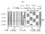
サーボ領域に形成されたパターンの一般的な構造と、サーボパターンからサーボ情報と呼ばれるヘッド位置信号を作成する方法を図14に示す。図14に示したパターンにおいて,ISG(Initial Signal Gain)部はディスクの記録膜の磁気特性や浮上量のむらの影響を低減するために設けられた連続パターンである。サーボ復調回路はオートゲインコントロール(AGC)をONにしてISG部を再生する。SVAM(SerVo Address Mark)部を検出した時点でAGCをOFFにすることにより,以降のバースト部の再生振幅をISG部の振幅で規格化する機能を実現している。グレイコード部は各トラックのトラック番号情報をグレイコードにより記述した部分である。この部分にセクタ番号の情報を併せて記述することもある。バースト部は半径方向の正確な位置情報を得るための千鳥格子状のパターンであり,ヘッドが各トラックを正確に追従するために必要な部分である。このパターンは,サーボトラックの境界線上において隣接する各サーボトラックの中心線に等しくまたがるように設けられたAバースト及びBバーストの組みと,各サーボトラックの中心線上に設けられたCバースト及びDバーストの組みから構成されている。パッド部はサーボ復調回路がサーボ領域を再生する間のクロック生成を維持できるように復調回路系の遅延を吸収するために設けられるパターンである。
【0009】
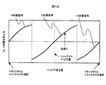
ヘッドは図14の左から右方向に矢印で示した位置Cを走行しながらサーボ領域の再生を行う。このときの再生波形の一部を図15に示す。説明を簡単にするため,図15では、SVAM部,グレイコード部,パッド部の再生波形は省略している。サーボ復調回路はAバースト部からDバースト部まで4つのバースト部の振幅を検出する。それぞれのバースト部の再生信号はAD変換器によりデジタル値に変換されて,積分演算もしくはフーリエ演算により振幅値が検出される。Aバースト部の振幅値とBバースト部の振幅値の差がN位置信号となる。図中には振幅値の差をISG振幅で規格化する式が記述してあるが,この機能はサーボ復調回路がISG部の振幅が一定になるようにAGCを制御することにより実現している。同様にCバースト部とDバースト部の振幅値の差がQ位置信号となる。以上のようにして作製されたヘッドの位置信号を,図16に示す。ヘッドの中心がAバースト部とBバースト部に等しくまたがる位置BでN位置信号は0となり,この中心位置からのずれの量にほぼ比例してN位置信号は正負に変化する。例えば図15に示す再生波形(図14の位置Cでの再生波形)からは,図16中の位置CのN位置信号を得ることができる。
【0010】
磁気ヘッドの位置決めを制御するコントローラはNとQ位置信号の絶対値を比較し,正負を反転してつなぎ合わせることによって,連続した位置信号を作製する。多くのサーボパターンでは,N位置信号が0となる位置をフォロイングの目標としてボイスコイルモータの制御が行われる。この位置信号と目標位置との差を比較してボイスコイルモータへ投入する最適な電流値を演算することによって,フォロイングやシークなどの所定の動作を行う。
【0011】
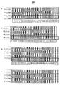
図17および図18を用いて、バースト部の形成手順の概要を説明する。太線で囲んだ部分が各ステップで記録されたパターンであり、パターンのトラック幅方向の幅が記録トラックの幅に相当する。太線で囲まれた部分の下部には記録パターンに相当する記録電流パターンを示す。図14および図15に示すように、ヘッドをデータトラックの間隔即ちトラックピッチの1/2の間隔で移動を行いながら、位相を合わせて異なるパターンを記録して行く。書きつなぎされる部分と直流消去される部分とがあり、結果として、千鳥格子上のバースト部が記録される。
【0012】
【発明が解決しようとする課題】
図19には、記録磁化パターンと再生波形との関係を、面内磁気記録方式と垂直磁気記録方式について対比して示す。面内磁気記録方式では、直流磁化に対するレスポンスを持たず、磁化転移部分でのみ単峰性の出力が得られるため、図19の(a)に示される記録磁化パターンの再生は波形は図19の(b)の様な波形になる。従って、上述のようなサーボパターンに対して、図20の(a)のような再生波形が得られ、位置信号情報を得るための絶対値積分検波信号は図20の(b)のようになり、各バーストの振幅レベルと積分検波信号の振幅レベルの大小関係はよく一致する。
【0013】
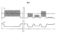
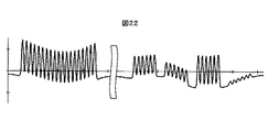
しかし、軟磁性裏打ち層を持つ二層垂直媒体においては、直流磁化に対するレスポンスを持ち、図19の(c)に示すような記録磁化に対する再生波形は図19の(d)の様になる。従って、面内記録と同様のサーボパターンに対する再生波形は、図21の(a)のようになり、DCオフセットを持つ波形となってしまう。位置信号情報を得るための絶対値積分検波信号は、図21の(b)のようになり、バーストの振幅レベルを正しく表せていない。また、AGCや再生アンプ等、実際の再生系回路系は直流成分を遮断する特性をもっているため、再生波形は、図22のように歪んだ波形となり、積分検波を行った場合、このDCオフセットの影響で正しい位置信号が得られない。
【0014】
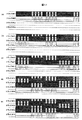
また、バースト部のバースト信号部は前出の図2の様に大きな直流消去部に囲まれるように配置されている。二層垂直記録では、短波長ほど記録ビット内の反磁界が小さいという性質から、長波長ほど熱減磁が大きいという特徴をもっている。図23は、記録密度が20KFCI、100KFCI、300KFCIの各記録密度での再生出力の経時変化のシミュレーション結果の例である。低い記録密度、即ち長波長ビットほど出力低下が大きいことが分かる。同様の効果により、前出の直流消去部の磁化から発生する磁界が隣接するサーボ信号部に影響を及ぼし、サーボ信号部の熱減磁を促進してしまう。
【0015】
また、ビットを記録する際に、下地として直流磁化が記録されている場合に、記録ビットのトラック端部が下地直流磁化の極性と一致するか否かでトラック幅方向にシフトする現象も報告されている。従って、バースト信号部においても、同様の現象により端部のシフトが起こり、位置信号の品質劣化を招く。
【0016】
また、従来、サーボ領域に記録される信号の最長ビット長はデータ領域の最長ビット長に比べて大きく、その状態ではサーボ領域の耐熱減磁性がもっとも弱いという設計になってしまい、信頼性が確保できないという問題もあった。
【0017】
【課題を解決するための手段】
上記問題を解決するために、本発明の磁気ディスク装置では、面内磁気記録方式において、従来サーボ部の直流消去領域であった領域、或いは非常に長い波長が記録されている領域に、バースト信号よりも短いビット長、即ちバースト信号よりも短波長の信号を記録することによりサーボ領域での反磁界を低減し、耐熱減磁性を高めると同時に、バースト信号部端部のシフトを抑制し、サーボ信号品質の向上が可能とする。本発明においては、上記のバースト信号よりも短波長の信号が記録されているサーボ部の直流消去領域をダミー領域と呼ぶこととする。
【0018】
一般に、再生ヘッドの感度は短波長の記録信号に対しては低下するので、ダミー領域に記録される信号の波長を十分短くしておけば、ダミー領域に記録された信号からの再生振幅はゼロに近く、位置信号の検出に影響が及ぶことはない。また、サーボトラックライタの性能上、ダミー領域に記録する記録信号の波長を十分短くできずに、ダミー領域に記録された信号の再生出力が無視できないほど大きい場合があるが、その場合は、ダミー領域に記録された信号の波長よりも短波長の信号を遮断するLPF(Low Pass Filter:低域通過フィルタ)を用いることによって、ダミー領域の記録信号の影響を除去することができる。
【0019】
ここで、ダミー領域に記録する信号周波数は、サーボパターンの信号周波数の整数倍に設定する方がサーボトラックライタの制御が容易になるため、装置製造時のスループットを大きくすることができ、コストメリットがある。
【0020】
また、本発明の磁気ディスク装置では、サーボ領域の最長ビット長を制限し、データ領域の最長ビット長と同程度あるいは短くする。垂直記録では、低密度信号の熱減磁が大きく、媒体上の記録データで記録密度の最も低い部分が最も熱揺らぎに弱い。サーボパターンはヘッド位置決めに不可欠なデータであり、ユーザデータ以上に熱揺らぎによる消失を防止する必要がある。そこで、サーボ領域のバースト信号部の記録ビット長を、ディスクに記録される信号の最長ビット長と同等か高くなるように設定し、その条件で耐熱減磁性を確保できるように装置を設計する。このようにサーボパターンを設計すれば、サーボパターンの耐熱減磁性は確保されていることになる。
【0021】
【発明の実施の形態】
第1の実施例
第1の実施例について説明する。本実施例では、面内磁気記録方式において、従来直流消去領域であった領域(図2の領域II参照)、即ちダミー領域に図1に示す様にバースト信号の2倍の記録密度、即ち1/2のビット長のパターンを記録したものである。
【0022】
図3および図4を用いてサーボライタでのバースト部の形成手順を説明する。
面内記録での従来方式と同様に1/2トラックピッチでバーストパターン形成を行うが、従来直流消去的であった領域にはバースト信号部の1/2のビットのパターンを記録していく。これにより、ダミー信号部をはさんだ千鳥格子状のバーストパターンが形成される。
【0023】
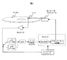
図5にサーボ系構成の概略を示す。面内磁気記録方式においても、再生アンプの後段には、高周波ノイズを遮断するためのLPFが設けられることが多いが、サーボ用とデータ用のLPFとを共用することが多い。本実施例においては、ダミー領域からの信号を遮断するためのLPFを用い、該LPFの遮断周波数を、ユーザデータ領域の記録信号を再生するときに用いられるLPFよりも低くする構成とした。LPFの前段には切り替えスイッチを配置し、スイッチの切り替えはHDCにより制御する。
【0024】
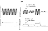
バースト信号部の記録密度はデータ領域の最高記録密度に比べてかなり低く、つまり、バースト信号部の記録信号周波数はデータ領域の記録信号周波数よりもかなり低い。本実施例においては、ダミー信号部の周波数はバースト信号部の周波数の2倍となっているが、2倍程度では周波数のダミー信号部からの再生信号は無視できない。従って、データ領域と同じ設定のLPFを用いた場合、図6に示すように本来ゼロであるべき領域でも信号が出てしまい、位置信号品質が劣化してしまう。そこで、バースト信号周波数は十分に通過させ、ダミー信号部の信号は遮断するような遮断周波数を持つLPFを通すことにより、ダミー信号部の振幅をゼロに近づけることができる。本実施例では、ダミー領域の周波数はバースト信号部の2倍であるので、サーボ用のLPFの遮断周波数はバースト信号周波数の1.5倍とした。これにより、バースト部の再生信号は図7に示すように、絶対値の積分波形が面内記録のときとほぼ同様の波形となり、従来のサーボ制御方式をそのまま利用することが出来る。
【0025】
尚、本実施例ではLPFを2つ持ち切り替える方式を用いているが、遮断周波数が可変のLPFを用い、遮断周波数を切り替えて使用することも当然可能である。
【0026】
第二の実施例
第2の実施例について説明する。本実施例では、バースト部の形成手順は第1の実施例と全く同様であるが、サーボ信号の処理系が異なる。図8に処理系の概要を示す。第1の実施例では絶対値の積分で振幅レベルの判定を行うが、本実施例では、DFT(離散フーリエ変換)を用いて周波数成分検出(位相サーボ制御)を行い、位置信号の制御を行う。サーボ信号の振幅ではなく周波数によりサーボ制御を行うため、また、ダミー領域の周波数はバースト信号部の周波数と異なるため、この方式では両者の弁別が容易である。従って、サーボ用のLPFを用意する必要がなく、データ領域と同等のLPFを用いることができる。
【0027】
第三の実施例
第3の実施例について説明する。本実施例では、バースト部の形成手順、サーボ信号の処理系は第2の実施例と全く同様であるが、バースト信号部の記録密度に条件を定めている。上述のように垂直記録では、低密度信号の熱減磁が大きい。従って、媒体上の記録データで記録密度の最も低い部分が最も熱揺らぎに弱いことになる。本実施例では、データ部の記録符号で制限された最も長いビット長よりも短いビット長でバースト信号を記録している。
【0028】
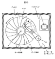
本実施例では、記録符号にとしてユーザーデータ32ビットに対して記録ビット33ビットを割り当てる効率32/33の符号を用いている。この符号では、最短記録ビットに対して、最長記録ビットは10倍のビット長となっている。本実施例の磁気ディスク装置では、図9に示すように、半径方向にゾーン分割し、各ゾーン毎に転送レートを固定してデータ記録を行っており、各半径位置と転送レートとの関係で各半径位置での線記録密度が決まる。本実施例では、最外周ゾーンでの記録密度が最も低く、このゾーンでの最長ビット長がこの装置でのデータ領域の最長ビット長となっている。従って、サーボ領域のバースト信号部の記録密度は、最長ビット長と同等か短くなるように設定する必要がある。本実施例では、最長ビット長と同じビット長に設定している。従って、ダミー信号部のビット長はその2倍とした。
【0029】
これにより、装置内の最長ビット長はデータ領域の最長ビット長と一致し、その条件で耐熱減磁性を確保していれば、サーボ信号の耐熱減磁性は確保されていることになる。従って、装置としての信頼性が確保されることになる。
【0030】
上記の実施例1から3では、軟磁性裏打ち層を持つ垂直磁気記録媒体を用いているが、軟磁性裏打ち層を持たない単層垂直磁気記録媒体を用いた場合でも、熱減磁に対する考え方は同じであり、低密度信号ほど熱減磁が大きい。また、再生波形も異なるが、サーボ部での処理については全く同様に行うことが出来る。従って、本発明は軟磁性裏打ち層を持たない垂直磁気記録媒体を用いた場合でも有効である。
【0031】
【発明の効果】
本発明によると、垂直磁気記録媒体を用いた磁気ディスク装置において、面内記録と同様のサーボ制御方式を用いることが可能となり、開発コストを低減することが出来る。また、熱減磁に弱い長波長信号を用いないために熱的に安定となり、更には、バースト信号のトラック幅方向の変動を抑制することにより、精度が高い位置信号を用いて位置決めが行えるため、信頼性の高い、大容量の磁気ディスク装置を提供することが可能となる。
【図面の簡単な説明】
【図1】本発明におけるバースト部パターンを説明する図。
【図2】従来のバースト部パターンを説明する図。
【図3】本発明におけるバースト部パターン形成手順を説明する図。
【図4】本発明におけるバースト部パターン形成手順を説明する図。
【図5】本発明における第一の実施例のサーボ系構成を説明する図。
【図6】本発明における第一の実施例のデータ用LPFを用いた場合のサーボ部再生波形を説明する図。
【図7】本発明における第一の実施例のサーボ部再生波形を説明する図。
【図8】本発明における第二の実施例のサーボ系構成を説明する図。
【図9】本発明における第3の実施例の装置構成を説明する図。
【図10】一般的な磁気ディスク装置構造例の平面図。
【図11】一般的な磁気ディスク装置構造例の断面図。
【図12】一般的な磁気ディスク装置構造例の拡大図。
【図13】一般的な磁気ディスク装置トラック構造例を説明する図。
【図14】一般的な磁気ディスク装置のサーボパターンを説明する図。
【図15】一般的な磁気ディスク装置のサーボパターン再生波形を説明する図。
【図16】一般的な磁気ディスク装置の位置信号を説明する図。
【図17】一般的な磁気ディスク装置のサーボパターン形成手順を説明する図。
【図18】一般的な磁気ディスク装置のサーボパターン形成手順を説明する図。
【図19】面内記録と垂直記録との再生の差異を説明する図。
【図20】従来磁気ディスク装置のサーボパターンを面内記録に適用した場合の再生波形を説明する図。
【図21】従来磁気ディスク装置のサーボパターンを垂直記録に適用した場合の再生波形を説明する図。
【図22】従来磁気ディスク装置のサーボパターンを低域遮断のある再生系を持つ垂直記録に適用した場合の再生波形を説明する図。
【図23】垂直磁気記録における熱減磁特性を説明する図。[0001]
BACKGROUND OF THE INVENTION
The present invention relates to a magnetic disk device using a perpendicular magnetic recording medium.
[0002]
[Prior art]
A magnetic disk device moves a head in a radial direction with respect to a rotating disk, accurately positions a target data track, and magnetically writes and reads information. FIG. 10 is a plan view of the inside of a casing (enclosure) of a typical magnetic disk device, and FIG. 11 is a cross-sectional view of the magnetic disk device. Here, a magnetic disk device composed of six heads, three disks, a rotary actuator, a voice coil motor, a head amplifier, a package board, etc. is shown as an example.
[0003]
The three disks are fixed to one rotating shaft and driven at a speed of 3000 to 15000 revolutions per minute around the point A by a spindle motor. The six heads are fixed to one comb-shaped arm, and are driven to rotate around point B by a rotary actuator. With this mechanism, the head can freely move in the radial direction of the disk. Since rotary actuators are suitable for downsizing the mechanism, all magnetic disk devices released in recent years adopt this type of actuator. Further, in order to detect the radial position of the head, servo areas are provided on the disk at substantially equal rotation angle intervals. Details of the arrangement of the servo area and the data area and means for detecting the radial position of the head from the servo area will be described later. A hard disk controller (HDC) for control, an interface circuit, a signal processing unit, and the like are mounted on the package board. The head amplifier is often mounted in an enclosure near the head in order to increase the S / N ratio and transfer speed.
[0004]
FIG. 12 shows an enlarged plan view of a part of the disk. The head can be moved to an arbitrary radial position of the disk by a rotary actuator, but is fixed at a specific radial position when writing and reading data. As shown in FIG. 12, concentric tracks are formed at almost equal intervals. Here, for the sake of explanation, only five tracks are shown by solid lines, but in actuality the tracks are magnetically formed and cannot be directly observed optically. In this figure, the track width is enlarged, but in an actual magnetic disk device, tens of thousands of tracks are formed over the inner and outer circumferences of the disk at a track interval smaller than 1 μm.
[0005]
In order to follow a specific track (following), a technology that records a special pattern called a servo pattern on the disk in advance before shipping the product and obtains the head position signal from this pattern is widely used. Yes. Such a technique is disclosed in, for example, Japanese Patent Application Laid-Open No. 58-222468. The servo pattern is formed in a portion indicated as a servo area in FIGS. The servo area and the data area are separated by a gap for absorbing fluctuations in rotational speed. Further, this data area is divided into about 600-byte sector blocks obtained by adding management information to 512-byte user data. The difference between the two areas is that the data area is frequently rewritten by a command from the user, whereas the servo area is not rewritten after product shipment.
[0006]
About 50 to 100 servo areas are provided on the disk at substantially equal angular intervals. Since the number of data areas is larger than that of the servo areas, there are several data areas between certain servo areas. Here, the data area (# 1) is arranged between the servo area (# 1) and the servo area (# 2), and the sector block (# 1) to the sector block (# 1) are included in the data area (# 1). An example in which there are three sector blocks up to # 3) is shown for a range of four tracks from track (# 1) to track (# 4). An actual magnetic disk device has 10,000 or more tracks, but in FIG. 13, the vertical direction is greatly enlarged.
[0007]
A pattern in which the timing in the bit direction is synchronized between tracks adjacent in the radial direction is recorded in the servo area. In order to form such a special pattern, a clock synchronized with the rotation of the disk is required. Normally, when recording a servo pattern, the servo pattern is recorded by a device called a servo track writer having such a function. A method for forming such a servo region is disclosed in, for example, Japanese Patent Application Laid-Open No. 64-48276.
[0008]
FIG. 14 shows a general structure of a pattern formed in the servo area and a method of creating a head position signal called servo information from the servo pattern. In the pattern shown in FIG. 14, an ISG (Initial Signal Gain) portion is a continuous pattern provided in order to reduce the influence of unevenness in the magnetic characteristics and flying height of the recording film of the disk. The servo demodulation circuit turns on auto gain control (AGC) and reproduces the ISG unit. By turning off the AGC when the SVAM (SerVo Address Mark) part is detected, the function of normalizing the reproduction amplitude of the subsequent burst part with the amplitude of the ISG part is realized. The gray code portion is a portion in which the track number information of each track is described in gray code. The sector number information may also be described in this part. The burst portion is a staggered pattern for obtaining accurate position information in the radial direction, and is a portion necessary for the head to accurately follow each track. This pattern consists of a set of A burst and B burst provided so as to equally extend over the center line of each adjacent servo track on the boundary line of the servo track, and C burst and D burst provided on the center line of each servo track. It consists of a set of. The pad portion is a pattern provided to absorb the delay of the demodulation circuit system so that the clock generation can be maintained while the servo demodulation circuit reproduces the servo area.
[0009]
The head reproduces the servo area while traveling from the left to the right in FIG. 14 at a position C indicated by an arrow. A part of the reproduction waveform at this time is shown in FIG. In order to simplify the explanation, the reproduction waveforms of the SVAM part, the gray code part, and the pad part are omitted in FIG. The servo demodulation circuit detects the amplitudes of the four burst parts from the A burst part to the D burst part. The reproduction signal of each burst part is converted into a digital value by an AD converter, and the amplitude value is detected by integration calculation or Fourier calculation. The difference between the amplitude value of the A burst portion and the amplitude value of the B burst portion is the N position signal. In the figure, an equation for normalizing the difference in amplitude value with the ISG amplitude is described. This function is realized by the servo demodulation circuit controlling the AGC so that the amplitude of the ISG unit is constant. . Similarly, the difference between the amplitude values of the C burst portion and the D burst portion becomes the Q position signal. FIG. 16 shows a position signal of the head manufactured as described above. The N position signal becomes 0 at the position B where the center of the head equally extends over the A burst portion and the B burst portion, and the N position signal changes in positive and negative in proportion to the amount of deviation from this center position. For example, an N position signal at position C in FIG. 16 can be obtained from the reproduction waveform shown in FIG. 15 (reproduction waveform at position C in FIG. 14).
[0010]
The controller that controls the positioning of the magnetic head compares the absolute values of the N and Q position signals and inverts the signs to create a continuous position signal. In many servo patterns, the voice coil motor is controlled by setting the position at which the N position signal is 0 as a following target. By comparing the difference between the position signal and the target position and calculating the optimum current value to be input to the voice coil motor, a predetermined operation such as following or seeking is performed.
[0011]
The outline of the procedure for forming the burst portion will be described with reference to FIGS. A portion surrounded by a bold line is a pattern recorded in each step, and the width of the pattern in the track width direction corresponds to the width of the recording track. A recording current pattern corresponding to the recording pattern is shown below the portion surrounded by the bold line. As shown in FIG. 14 and FIG. 15, different patterns are recorded in phase while moving the head at an interval of the data track, that is, an interval of 1/2 the track pitch. There are a part to be written and a part to be DC erased. As a result, a burst part on the staggered lattice is recorded.
[0012]
[Problems to be solved by the invention]
FIG. 19 shows the relationship between the recording magnetization pattern and the reproduction waveform for the in-plane magnetic recording method and the perpendicular magnetic recording method. In the in-plane magnetic recording method, there is no response to direct current magnetization, and a unimodal output can be obtained only at the magnetization transition portion. Therefore, the reproduction of the recording magnetization pattern shown in FIG. The waveform is as shown in (b). Accordingly, a reproduced waveform as shown in FIG. 20A is obtained for the servo pattern as described above, and an absolute value integrated detection signal for obtaining position signal information is as shown in FIG. 20B. The magnitude relationship between the amplitude level of each burst and the amplitude level of the integral detection signal agrees well.
[0013]
However, a two-layer perpendicular medium having a soft magnetic backing layer has a response to direct current magnetization, and a reproduction waveform for recording magnetization as shown in FIG. 19C is as shown in FIG. Accordingly, the reproduction waveform for the servo pattern similar to the in-plane recording is as shown in FIG. 21A, and has a waveform having a DC offset. The absolute value integral detection signal for obtaining the position signal information is as shown in FIG. 21B, and does not correctly represent the burst amplitude level. Further, since an actual reproduction system circuit system such as an AGC or a reproduction amplifier has a characteristic of cutting off a direct current component, the reproduction waveform becomes a distorted waveform as shown in FIG. The correct position signal cannot be obtained due to the influence.
[0014]
The burst signal portion of the burst portion is arranged so as to be surrounded by a large DC erasure portion as shown in FIG. Double-layer perpendicular recording is characterized by the fact that the shorter the wavelength, the smaller the demagnetizing field in the recording bit, and the longer the wavelength, the greater the thermal demagnetization. FIG. 23 is an example of a simulation result of a change in reproduction output with time at recording densities of 20 KFCI, 100 KFCI, and 300 KFCI. It can be seen that the lower the recording density, that is, the longer wavelength bit, the greater the output drop. Due to the same effect, the magnetic field generated from the magnetization of the direct current erasing unit described above affects the adjacent servo signal unit and promotes thermal demagnetization of the servo signal unit.
[0015]
In addition, when DC magnetization is recorded as a base when recording a bit, a phenomenon that the track end of the recording bit shifts in the track width direction depending on whether or not the polarity of the base DC magnetization matches is reported. ing. Accordingly, in the burst signal portion, the end shift occurs due to the same phenomenon, and the quality of the position signal is deteriorated.
[0016]
Conventionally, the longest bit length of the signal recorded in the servo area is larger than the longest bit length of the data area, and the heat resistance demagnetization of the servo area is the weakest in that state, ensuring reliability. There was also a problem that it was not possible.
[0017]
[Means for Solving the Problems]
In order to solve the above problem, in the magnetic disk apparatus of the present invention, in the in-plane magnetic recording system, a burst signal is applied to a region that has been a DC erasing region of a conventional servo unit or a region in which a very long wavelength is recorded. By recording a signal with a shorter bit length, that is, a shorter wavelength than the burst signal, the demagnetizing field in the servo area is reduced, the heat demagnetization is increased, and at the same time, the shift of the end of the burst signal part is suppressed, and the servo Signal quality can be improved. In the present invention, the DC erasure area of the servo section in which a signal having a shorter wavelength than the burst signal is recorded is called a dummy area.
[0018]
In general, since the sensitivity of the reproducing head decreases for a short wavelength recording signal, if the wavelength of the signal recorded in the dummy area is sufficiently short, the reproducing amplitude from the signal recorded in the dummy area is zero. The position signal detection is not affected. Also, due to the performance of the servo track writer, the wavelength of the recording signal recorded in the dummy area cannot be made sufficiently short, and the reproduction output of the signal recorded in the dummy area may be so large that it cannot be ignored. By using an LPF (Low Pass Filter) that cuts off a signal having a shorter wavelength than the wavelength of the signal recorded in the area, the influence of the recording signal in the dummy area can be eliminated.
[0019]
Here, it is easier to control the servo track writer by setting the signal frequency to be recorded in the dummy area to an integer multiple of the signal frequency of the servo pattern. There is.
[0020]
In the magnetic disk device of the present invention, the longest bit length of the servo area is limited to be the same as or shorter than the longest bit length of the data area. In the perpendicular recording, the thermal demagnetization of the low density signal is large, and the lowest recording density portion of the recording data on the medium is the weakest to the thermal fluctuation. The servo pattern is indispensable data for head positioning, and it is necessary to prevent disappearance due to thermal fluctuations more than user data. Therefore, the recording bit length of the burst signal portion in the servo area is set to be equal to or higher than the longest bit length of the signal recorded on the disk, and the apparatus is designed so as to ensure heat-resistant demagnetization under the conditions. If the servo pattern is designed in this way, the heat resistance demagnetization of the servo pattern is ensured.
[0021]
DETAILED DESCRIPTION OF THE INVENTION
First Embodiment A first embodiment will be described. In this embodiment, in the in-plane magnetic recording system, the recording density twice as high as the burst signal, that is, 1 in the area (refer to area II in FIG. 2), which is a conventional DC erasure area, as shown in FIG. A pattern with a bit length of / 2 is recorded.
[0022]
A procedure for forming a burst portion in the servo writer will be described with reference to FIGS.
A burst pattern is formed at a 1/2 track pitch in the same manner as in the conventional method for in-plane recording, but a 1/2 bit pattern of the burst signal portion is recorded in a region that has been conventionally DC erasable. As a result, a staggered burst pattern sandwiching the dummy signal portions is formed.
[0023]
FIG. 5 shows an outline of the servo system configuration. Even in the in-plane magnetic recording system, an LPF for blocking high-frequency noise is often provided after the reproduction amplifier, but the servo and data LPFs are often shared. In this embodiment, an LPF for blocking a signal from the dummy area is used, and the cutoff frequency of the LPF is set lower than the LPF used when reproducing the recording signal in the user data area. A changeover switch is arranged in front of the LPF, and the changeover of the switch is controlled by the HDC.
[0024]
The recording density of the burst signal part is considerably lower than the maximum recording density of the data area, that is, the recording signal frequency of the burst signal part is considerably lower than the recording signal frequency of the data area. In this embodiment, the frequency of the dummy signal portion is twice that of the burst signal portion. However, when the frequency is about twice, the reproduction signal from the dummy signal portion of the frequency cannot be ignored. Therefore, when an LPF having the same setting as that of the data area is used, a signal is output even in an area that should be zero as shown in FIG. 6, and the position signal quality deteriorates. Therefore, the amplitude of the dummy signal portion can be brought close to zero by passing the LPF having a cutoff frequency that allows the burst signal frequency to pass sufficiently and blocks the signal of the dummy signal portion. In this embodiment, since the frequency of the dummy area is twice that of the burst signal portion, the cutoff frequency of the servo LPF is set to 1.5 times the burst signal frequency. As a result, as shown in FIG. 7, the reproduction signal of the burst part has an almost integrated waveform of the absolute value when in-plane recording, and the conventional servo control method can be used as it is.
[0025]
In this embodiment, a method of switching between two LPFs is used. However, it is naturally possible to use an LPF having a variable cutoff frequency and switch the cutoff frequency.
[0026]
Second Embodiment A second embodiment will be described. In this embodiment, the procedure for forming the burst portion is exactly the same as in the first embodiment, but the servo signal processing system is different. FIG. 8 shows an outline of the processing system. In the first embodiment, the amplitude level is determined by integrating the absolute value, but in this embodiment, frequency component detection (phase servo control) is performed using DFT (discrete Fourier transform) to control the position signal. . Since servo control is performed not by the amplitude of the servo signal but by the frequency, and because the frequency of the dummy area is different from the frequency of the burst signal part, it is easy to discriminate both in this system. Therefore, it is not necessary to prepare an LPF for servo, and an LPF equivalent to the data area can be used.
[0027]
Third Embodiment A third embodiment will be described. In this embodiment, the procedure for forming the burst portion and the servo signal processing system are the same as those in the second embodiment, but conditions are set for the recording density of the burst signal portion. As described above, in the perpendicular recording, the thermal demagnetization of the low density signal is large. Accordingly, the lowest recording density portion of the recording data on the medium is the weakest to the thermal fluctuation. In this embodiment, the burst signal is recorded with a bit length shorter than the longest bit length limited by the recording code of the data portion.
[0028]
In the present embodiment, a code of efficiency 32/33 that allocates 33 recording bits to 32 bits of user data is used as a recording code. In this code, the longest recording bit is 10 times as long as the shortest recording bit. In the magnetic disk apparatus of this embodiment, as shown in FIG. 9, data is recorded by dividing the zone in the radial direction and fixing the transfer rate for each zone, and the relationship between each radial position and the transfer rate. The linear recording density at each radial position is determined. In this embodiment, the recording density in the outermost peripheral zone is the lowest, and the longest bit length in this zone is the longest bit length of the data area in this apparatus. Accordingly, it is necessary to set the recording density of the burst signal portion in the servo area so as to be equal to or shorter than the longest bit length. In this embodiment, the same bit length as the longest bit length is set. Accordingly, the bit length of the dummy signal portion is set to twice that length.
[0029]
As a result, the longest bit length in the device matches the longest bit length of the data area, and if heat demagnetization is ensured under the conditions, the heat demagnetization of the servo signal is ensured. Therefore, reliability as a device is ensured.
[0030]
In Examples 1 to 3 described above, a perpendicular magnetic recording medium having a soft magnetic backing layer is used. However, even when a single-layer perpendicular magnetic recording medium having no soft magnetic backing layer is used, there is no way of thinking about thermal demagnetization. The same is true, and the lower the signal, the greater the thermal demagnetization. Although the reproduction waveform is different, the processing in the servo section can be performed in exactly the same way. Therefore, the present invention is effective even when a perpendicular magnetic recording medium having no soft magnetic underlayer is used.
[0031]
【The invention's effect】
According to the present invention, in a magnetic disk device using a perpendicular magnetic recording medium, it is possible to use the same servo control method as in the in-plane recording, and the development cost can be reduced. In addition, because it does not use a long-wavelength signal that is weak against thermal demagnetization, it becomes thermally stable, and furthermore, by controlling fluctuations in the track width direction of the burst signal, positioning can be performed using a highly accurate position signal. It is possible to provide a highly reliable and large capacity magnetic disk device.
[Brief description of the drawings]
FIG. 1 is a diagram for explaining a burst pattern in the present invention.
FIG. 2 is a diagram for explaining a conventional burst pattern.
FIG. 3 is a view for explaining a burst pattern forming procedure in the present invention.
FIG. 4 is a view for explaining a burst pattern forming procedure in the present invention.
FIG. 5 is a diagram for explaining a servo system configuration according to the first embodiment of the present invention;
FIG. 6 is a diagram for explaining a servo unit reproduction waveform when the data LPF according to the first embodiment of the present invention is used.
FIG. 7 is a diagram for explaining a servo unit reproduction waveform according to the first embodiment of the present invention.
FIG. 8 is a diagram illustrating a servo system configuration according to a second embodiment of the present invention.
FIG. 9 is a diagram for explaining a device configuration of a third embodiment of the present invention.
FIG. 10 is a plan view of a typical structure of a magnetic disk device.
FIG. 11 is a cross-sectional view of a typical structure example of a magnetic disk device.
FIG. 12 is an enlarged view of a typical structure of a magnetic disk device.
FIG. 13 is a diagram for explaining an example of a general magnetic disk device track structure;
FIG. 14 is a diagram illustrating a servo pattern of a general magnetic disk device.
FIG. 15 is a diagram for explaining a servo pattern reproduction waveform of a general magnetic disk device.
FIG. 16 is a diagram illustrating a position signal of a general magnetic disk device.
FIG. 17 is a diagram for explaining a servo pattern forming procedure of a general magnetic disk device.
FIG. 18 is a diagram for explaining a servo pattern forming procedure of a general magnetic disk device.
FIG. 19 is a diagram for explaining a reproduction difference between in-plane recording and vertical recording.
FIG. 20 is a diagram for explaining a reproduction waveform when a servo pattern of a conventional magnetic disk device is applied to in-plane recording.
FIG. 21 is a diagram for explaining a reproduction waveform when a servo pattern of a conventional magnetic disk device is applied to perpendicular recording.
FIG. 22 is a diagram for explaining a reproduction waveform when a servo pattern of a conventional magnetic disk device is applied to perpendicular recording having a reproduction system with low-frequency cutoff.
FIG. 23 is a diagram for explaining thermal demagnetization characteristics in perpendicular magnetic recording.
Claims (21)
前記垂直記録媒体は、該磁気ヘッドの位置決め信号が記録されたサーボ領域と、ユーザデータが記録されるユーザデータ領域とを有し、
前記サーボ領域はバースト部を有し、
前記バースト部は、当該バースト部内に千鳥状に配置され、半径方向の位置情報を得るためのバースト信号が記録された第1の領域と、前記バースト部内で前記第1の領域をトラック方向及びトラック幅方向に囲む領域に、反磁界を低減するためのダミー信号が記録された第2の領域とを有し、
前記ダミー信号は、前記バースト信号の周波数よりも高い周波数を有する信号であって、位置決めには用いられない、ことを特徴とする垂直磁気記録装置。A magnetic head for recording and reproducing information, and a perpendicular magnetic recording medium having a perpendicular recording layer,
The perpendicular recording medium has a servo area in which a positioning signal of the magnetic head is recorded, and a user data area in which user data is recorded ,
The servo area has a burst portion;
The burst section is arranged in a staggered manner in the burst section, and a first area in which a burst signal for obtaining position information in the radial direction is recorded, and the first area in the burst section is divided into a track direction and a track A second region in which a dummy signal for reducing a demagnetizing field is recorded in a region surrounded in the width direction;
The perpendicular magnetic recording apparatus according to claim 1, wherein the dummy signal is a signal having a frequency higher than that of the burst signal, and is not used for positioning.
前記ダミー信号の周波数は、前記バースト信号の周波数の2倍以上であることを特徴とする垂直磁気記録装置。The perpendicular magnetic recording apparatus according to claim 1,
2. The perpendicular magnetic recording apparatus according to claim 1 , wherein the frequency of the dummy signal is at least twice that of the burst signal.
前記第1の領域は、トラック方向及びトラック幅方向を第2の領域に囲まれていることを特徴とする垂直磁気記録装置。The perpendicular magnetic recording apparatus according to claim 1 or 2,
The perpendicular magnetic recording apparatus according to claim 1, wherein the first area is surrounded by a second area in a track direction and a track width direction.
前記ダミー信号は、DCオフセットを抑制することを特徴とする垂直磁気記録装置。The perpendicular magnetic recording apparatus according to any one of claims 1 to 3,
The perpendicular magnetic recording apparatus according to claim 1, wherein the dummy signal suppresses a DC offset.
前記垂直磁気記録媒体は、前記垂直記録層より下に軟磁性裏打ち層を持つことを特徴とする垂直磁気記録装置。The perpendicular magnetic recording apparatus according to any one of claims 1 to 4,
The perpendicular magnetic recording apparatus, wherein the perpendicular magnetic recording medium has a soft magnetic backing layer below the perpendicular recording layer.
前記垂直磁気記録媒体は、直流磁化に対するレスポンスを持つことを特徴とする垂直磁気記録装置。The perpendicular magnetic recording apparatus according to any one of claims 1 to 5,
The perpendicular magnetic recording apparatus, wherein the perpendicular magnetic recording medium has a response to direct current magnetization.
前記ダミー信号の最低周波数は、前記ユーザデータ領域に記録される信号の最低記録周波数よりも高いことを特徴とする垂直磁気記録装置。In the perpendicular magnetic recording apparatus according to any one of claims 1 to 6,
The perpendicular magnetic recording apparatus according to claim 1, wherein a minimum frequency of the dummy signal is higher than a minimum recording frequency of a signal recorded in the user data area.
前記ダミー信号の周波数は、前記サーボ信号が記録された領域の周波数の整数倍であることを特徴とする垂直磁気記録装置。The perpendicular magnetic recording apparatus according to any one of claims 1 to 7,
2. The perpendicular magnetic recording apparatus according to claim 1, wherein the frequency of the dummy signal is an integral multiple of the frequency of the area where the servo signal is recorded.
前記ダミー信号が記録された領域は、前記バースト部のうち、前記バースト信号が書かれている領域を除く全領域であることを特徴とする垂直磁気記録装置。The perpendicular magnetic recording apparatus according to any one of claims 1 to 8,
2. The perpendicular magnetic recording apparatus according to claim 1, wherein the area where the dummy signal is recorded is the entire area of the burst portion excluding the area where the burst signal is written.
前記ダミー信号が記録された領域からの再生信号振幅は略ゼロであることを特徴とする垂直磁気記録装置。The perpendicular magnetic recording apparatus according to any one of claims 1 to 9,
2. A perpendicular magnetic recording apparatus according to claim 1, wherein a reproduction signal amplitude from an area where the dummy signal is recorded is substantially zero.
前記垂直記録媒体は、該磁気ヘッドの位置決め信号が記録されたサーボ領域と、ユーザデータが記録されるユーザデータ領域とを有し、
前記サーボ領域はバースト部を有し、
前記バースト部は、当該バースト部内に千鳥状に配置され、半径方向の位置情報を得るためのバースト信号が記録された第1の領域と、前記バースト部内で前記第1の領域をトラック方向及びトラック幅方向に囲む領域に、反磁界を低減するためのダミー信号が記録された第2の領域とを有し、
前記ダミー信号は、前記バースト信号のビット長よりも短いビット長を有する信号であって、位置決めには用いられない、ことを特徴とする垂直磁気記録装置。A magnetic head for recording and reproducing information, and a perpendicular magnetic recording medium having a perpendicular recording layer,
The perpendicular recording medium has a servo area in which a positioning signal of the magnetic head is recorded, and a user data area in which user data is recorded,
The servo area has a burst portion;
The burst section is arranged in a staggered manner in the burst section, and a first area in which a burst signal for obtaining position information in the radial direction is recorded, and the first area in the burst section is divided into a track direction and a track A second region in which a dummy signal for reducing a demagnetizing field is recorded in a region surrounded in the width direction;
The perpendicular magnetic recording apparatus according to claim 1, wherein the dummy signal is a signal having a bit length shorter than that of the burst signal and is not used for positioning.
前記ダミー信号のビット長は、前記バースト信号のビット長の1/2以下であることを特徴とする垂直磁気記録装置。The perpendicular magnetic recording apparatus according to claim 11, wherein
The perpendicular magnetic recording apparatus according to claim 1, wherein a bit length of the dummy signal is 1/2 or less of a bit length of the burst signal.
前記第1の領域は、トラック方向及びトラック幅方向を前記第2の領域に囲まれていることを特徴とする垂直磁気記録装置。The perpendicular magnetic recording apparatus according to claim 11 or 12,
The perpendicular magnetic recording apparatus according to claim 1, wherein the first area is surrounded by the second area in a track direction and a track width direction.
前記ダミー信号はDCオフセットを抑制することを特徴とする垂直磁気記録装置。14. The perpendicular magnetic recording apparatus according to claim 11, wherein:
The perpendicular magnetic recording apparatus according to claim 1, wherein the dummy signal suppresses a DC offset.
前記垂直磁気記録媒体は、前記垂直磁気記録層より下に軟磁性裏打ち層を持つことを特徴とする垂直磁気記録装置。The perpendicular magnetic recording apparatus according to any one of claims 11 to 14,
The perpendicular magnetic recording apparatus, wherein the perpendicular magnetic recording medium has a soft magnetic backing layer below the perpendicular magnetic recording layer.
前記垂直磁気記録媒体は、直流磁化に対するレスポンスを持つことを特徴とする垂直磁気記録装置。The perpendicular magnetic recording apparatus according to any one of claims 11 to 15,
The perpendicular magnetic recording apparatus, wherein the perpendicular magnetic recording medium has a response to direct current magnetization.
前記ダミー信号の最低ビット長は、前記ユーザデータ領域に記録される信号の最低ビット長よりも短いことを特徴とする垂直磁気記録装置。The perpendicular magnetic recording apparatus according to any one of claims 11 to 16,
The perpendicular magnetic recording apparatus according to claim 1, wherein a minimum bit length of the dummy signal is shorter than a minimum bit length of a signal recorded in the user data area.
前記ダミー信号のビット長は、前記サーボ領域に記録された信号のビット長の整数倍であることを特徴とする垂直磁気記録装置。The perpendicular magnetic recording apparatus according to any one of claims 11 to 17,
The perpendicular magnetic recording apparatus according to claim 1, wherein the bit length of the dummy signal is an integral multiple of the bit length of the signal recorded in the servo area.
前記ダミー信号が記録された領域は、前記バースト部のうち、前記バースト信号が書かれている領域を除く全領域であることを特徴とする垂直磁気記録装置。The perpendicular magnetic recording apparatus according to any one of claims 11 to 18,
2. The perpendicular magnetic recording apparatus according to claim 1, wherein the area where the dummy signal is recorded is the entire area of the burst portion excluding the area where the burst signal is written.
前記ダミー信号が記録された領域からの再生信号振幅は略ゼロであることを特徴とする垂直磁気記録装置。The perpendicular magnetic recording apparatus according to any one of claims 11 to 19,
2. A perpendicular magnetic recording apparatus according to claim 1, wherein a reproduction signal amplitude from an area where the dummy signal is recorded is substantially zero.
前記第2の領域の記録密度は、前記第1の領域の記録密度よりも高いことを特徴とする垂直磁気記録装置。The perpendicular magnetic recording apparatus according to any one of claims 1 to 20,
The perpendicular magnetic recording apparatus according to claim 1, wherein the recording density of the second area is higher than the recording density of the first area.
Priority Applications (6)
| Application Number | Priority Date | Filing Date | Title |
|---|---|---|---|
| JP2000349312A JP4644356B2 (en) | 2000-11-10 | 2000-11-10 | Servo write system for magnetic disk device and magnetic recording / reproducing device |
| US09/924,762 US7075743B2 (en) | 2000-11-10 | 2001-08-09 | Method of servo writing for magnetic recording system, magnetic recording system |
| EP01119609A EP1205911A3 (en) | 2000-11-10 | 2001-08-17 | The method of servo writing for magnetic recording system, magnetic recording system |
| KR1020010052865A KR100867789B1 (en) | 2000-11-10 | 2001-08-30 | Vertical magnetic recording system |
| US11/377,367 US7436611B2 (en) | 2000-11-10 | 2006-03-17 | Method of servo writing for magnetic recording system, magnetic recording system |
| US12/230,989 US7839590B2 (en) | 2000-11-10 | 2008-09-09 | Method of servo writing for magnetic recording system, magnetic recording system |
Applications Claiming Priority (1)
| Application Number | Priority Date | Filing Date | Title |
|---|---|---|---|
| JP2000349312A JP4644356B2 (en) | 2000-11-10 | 2000-11-10 | Servo write system for magnetic disk device and magnetic recording / reproducing device |
Related Child Applications (1)
| Application Number | Title | Priority Date | Filing Date |
|---|---|---|---|
| JP2006066898A Division JP4340665B2 (en) | 2006-03-13 | 2006-03-13 | Servo write system for magnetic disk device and magnetic recording / reproducing device |
Publications (3)
| Publication Number | Publication Date |
|---|---|
| JP2002150729A JP2002150729A (en) | 2002-05-24 |
| JP2002150729A5 JP2002150729A5 (en) | 2006-06-08 |
| JP4644356B2 true JP4644356B2 (en) | 2011-03-02 |
Family
ID=18822736
Family Applications (1)
| Application Number | Title | Priority Date | Filing Date |
|---|---|---|---|
| JP2000349312A Expired - Fee Related JP4644356B2 (en) | 2000-11-10 | 2000-11-10 | Servo write system for magnetic disk device and magnetic recording / reproducing device |
Country Status (4)
| Country | Link |
|---|---|
| US (3) | US7075743B2 (en) |
| EP (1) | EP1205911A3 (en) |
| JP (1) | JP4644356B2 (en) |
| KR (1) | KR100867789B1 (en) |
Families Citing this family (20)
| Publication number | Priority date | Publication date | Assignee | Title |
|---|---|---|---|---|
| JP4644356B2 (en) * | 2000-11-10 | 2011-03-02 | 株式会社日立グローバルストレージテクノロジーズ | Servo write system for magnetic disk device and magnetic recording / reproducing device |
| JP2005004917A (en) * | 2003-06-13 | 2005-01-06 | Hitachi Ltd | Vertical magnetic recording medium and magnetic disk unit |
| JP2005276292A (en) | 2004-03-24 | 2005-10-06 | Fuji Photo Film Co Ltd | Master carrier for magnetic transfer, magnetic transfer method, and magnetic recording medium |
| JP4358067B2 (en) * | 2004-08-06 | 2009-11-04 | 株式会社東芝 | Magnetic recording medium and magnetic recording apparatus |
| CN100367363C (en) * | 2004-09-01 | 2008-02-06 | Tdk股份有限公司 | Information recording medium, recording/reproducing apparatus, and stamper |
| CN100367364C (en) * | 2004-09-01 | 2008-02-06 | Tdk股份有限公司 | Information recording medium, recording/reproducing apparatus, and stamper |
| US7342734B1 (en) * | 2004-09-02 | 2008-03-11 | Maxtor Corporation | Disk drives with radially aligned servo burst patterns that generate orthogonal contributions to a read signal and related demodulators and methods |
| JP4077437B2 (en) | 2004-09-16 | 2008-04-16 | Tdk株式会社 | Information recording medium and recording / reproducing apparatus |
| US7068461B1 (en) | 2004-11-29 | 2006-06-27 | Western Digital Technologies, Inc. | Servo writing a disk drive by overwriting a harmonic frequency fill pattern in the servo burst area |
| KR100594308B1 (en) * | 2004-12-27 | 2006-06-30 | 삼성전자주식회사 | Method for recording servo pattern on disc and disc drive and magnetic disc using the same |
| JP4291784B2 (en) * | 2005-01-12 | 2009-07-08 | ヒタチグローバルストレージテクノロジーズネザーランドビーブイ | Servo information recording method, magnetic recording medium, and magnetic disk apparatus |
| KR100660885B1 (en) * | 2005-11-07 | 2006-12-26 | 삼성전자주식회사 | Burst recording method of hard disk drive and apparatus thereof |
| JP2007242152A (en) * | 2006-03-09 | 2007-09-20 | Fujitsu Ltd | Magnetic recording medium, magnetic recorder, and servo demodulation circuit |
| JP2007293930A (en) * | 2006-04-20 | 2007-11-08 | Hitachi Global Storage Technologies Netherlands Bv | Method for writing servo pattern on recording surface and data storage device |
| JP4589894B2 (en) * | 2006-05-31 | 2010-12-01 | 東芝ストレージデバイス株式会社 | Magnetic disk device and magnetic disk device manufacturing method |
| US20080316635A1 (en) * | 2007-06-20 | 2008-12-25 | Samsung Electronics Co., Ltd. | Deriving servo PES from DC erased bursts in perpendicular recording |
| US7688538B1 (en) | 2007-11-16 | 2010-03-30 | Western Digital Technologies, Inc. | Disk drive comprising a disk surface having track addresses of varying width |
| US7986488B2 (en) * | 2008-12-04 | 2011-07-26 | Hitachi Global Storage Technologies Netherlands B.V. | Magnetic recording disk and disk drive with alternating single-polarity position error signal (PES) blocks for read/write head positioning |
| US7982993B1 (en) * | 2008-12-19 | 2011-07-19 | Western Digital Technologies, Inc. | Disk drive employing different servo TPI to data TPI ratios across the disk surface |
| US8031423B1 (en) | 2009-06-26 | 2011-10-04 | Western Digital Technologies, Inc. | Disk drive generating actual data TPI profile by combining segments of predetermined data TPI profiles |
Family Cites Families (38)
| Publication number | Priority date | Publication date | Assignee | Title |
|---|---|---|---|---|
| US4188646A (en) * | 1978-05-30 | 1980-02-12 | Sperry Rand Corporation | Sectorized data path following servo system |
| US4472750A (en) * | 1981-07-02 | 1984-09-18 | Irwin Magnetic Systems, Inc. | Data record with pre-recorded transducer positioning signals, and system for utilizing same |
| EP0097208B1 (en) | 1982-06-18 | 1987-03-11 | International Business Machines Corporation | Head positioning system with automatic gain control |
| US4454549A (en) * | 1982-06-28 | 1984-06-12 | International Business Machines Corporation | Slant track sector servo |
| US4530020A (en) * | 1984-06-06 | 1985-07-16 | Dma Systems | Self-timed runout correction pattern |
| US4912576A (en) * | 1985-11-20 | 1990-03-27 | Magnetic Peripherals Inc. | Method for writing a servo pattern |
| JPS63140469A (en) * | 1986-12-03 | 1988-06-13 | Fuji Electric Co Ltd | Detecting system for reference track of disk memory device |
| US5453887A (en) * | 1987-01-13 | 1995-09-26 | Canon Denshi Kabushiki Kaisha | Head tracking servo pattern |
| JPS6448276A (en) | 1987-08-17 | 1989-02-22 | Nec Corp | Servo track writing device |
| JPH0434060Y2 (en) | 1987-09-22 | 1992-08-13 | ||
| US5036408A (en) * | 1988-05-12 | 1991-07-30 | Digital Equipment Corporation | High efficiency disk format and synchronization system |
| US5121270A (en) * | 1989-09-19 | 1992-06-09 | Alcudia Ezra R | Multitransducer head positioning servo for use in a bi-directional magnetic tape system |
| US5170299A (en) * | 1990-08-17 | 1992-12-08 | Quantum Corporation | Edge servo for disk drive head positioner |
| JP2799071B2 (en) * | 1990-11-21 | 1998-09-17 | 株式会社東芝 | Magnetic recording / reproducing device |
| JPH07122047A (en) | 1993-09-02 | 1995-05-12 | Toshiba Corp | Magnetic disk device |
| JPH07121804A (en) | 1993-10-22 | 1995-05-12 | Sony Corp | Magnetic memory system |
| US5680283A (en) * | 1994-09-30 | 1997-10-21 | Kabushiki Kaisha Toshiba | Magnetic head and magnetic disk drive |
| US5862005A (en) * | 1994-10-11 | 1999-01-19 | Quantum Corporation | Synchronous detection of wide bi-phase coded servo information for disk drive |
| JPH08255306A (en) | 1995-03-16 | 1996-10-01 | Toshiba Corp | Data recording and reproducing system |
| US5870591A (en) * | 1995-08-11 | 1999-02-09 | Fujitsu Limited | A/D with digital PLL |
| JPH0963217A (en) * | 1995-08-23 | 1997-03-07 | Toshiba Corp | Method for recording servo information on magnetic disk |
| US6411452B1 (en) * | 1997-03-11 | 2002-06-25 | Western Digital Technologies, Inc. | Disk drive employing read error tolerant sync mark detection |
| US6134070A (en) * | 1997-05-22 | 2000-10-17 | Imation Corp. | Encoded servo track configurations, servo writer and systems/method regarding same |
| JP3663033B2 (en) | 1997-07-28 | 2005-06-22 | 株式会社東芝 | Magnetic disk apparatus using MR head and reproduction signal processing method in the apparatus |
| US6025970A (en) * | 1997-08-07 | 2000-02-15 | International Business Machines Corporation | Digital demodulation of a complementary two-frequency servo PES pattern |
| US6078445A (en) * | 1997-08-07 | 2000-06-20 | International Business Machines Corporation | Gain control for a dual burst, dual frequency PES servo pattern |
| US5966264A (en) * | 1997-08-07 | 1999-10-12 | International Business Machines Cororation | Two frequency servo PES pattern |
| JP4206142B2 (en) | 1998-02-04 | 2009-01-07 | 株式会社日立グローバルストレージテクノロジーズ | Position signal recording method and magnetic recording apparatus using the same |
| JP3334628B2 (en) * | 1998-07-27 | 2002-10-15 | 松下電器産業株式会社 | Method of writing tracking servo signal pattern in magnetic disk drive |
| US6262859B1 (en) * | 1998-08-11 | 2001-07-17 | Samsung Electronics Company | Method and apparatus for providing servo information on a disk in a hard drive assembly |
| US6236525B1 (en) * | 1998-08-14 | 2001-05-22 | Storage Technology Corporation | Tape head with pattern timing for servo writing application |
| US6602620B1 (en) * | 1998-12-28 | 2003-08-05 | Kabushiki Kaisha Toshiba | Magnetic recording apparatus, magnetic recording medium and manufacturing method thereof |
| JP3757071B2 (en) * | 1999-01-21 | 2006-03-22 | 株式会社日立グローバルストレージテクノロジーズ | Magnetic disk unit |
| US6490111B1 (en) * | 1999-08-25 | 2002-12-03 | Seagate Technology Llc | Method and apparatus for refreshing servo patterns in a disc drive |
| US6359744B1 (en) | 1999-09-13 | 2002-03-19 | Maxtor Corporation | Reducing thermal decay of data signals recorded on magnetic media |
| US6731446B2 (en) * | 2000-02-03 | 2004-05-04 | Matsushita Electric Industrial Co., Ltd. | Method for forming a magnetic pattern in a magnetic recording medium, method for producing a magnetic recording medium, magnetic pattern forming device, magnetic recording medium and magnetic recording device |
| JP4644356B2 (en) * | 2000-11-10 | 2011-03-02 | 株式会社日立グローバルストレージテクノロジーズ | Servo write system for magnetic disk device and magnetic recording / reproducing device |
| JP4102600B2 (en) * | 2002-06-03 | 2008-06-18 | 株式会社日立グローバルストレージテクノロジーズ | Magnetic disk apparatus and signal processing apparatus |
-
2000
- 2000-11-10 JP JP2000349312A patent/JP4644356B2/en not_active Expired - Fee Related
-
2001
- 2001-08-09 US US09/924,762 patent/US7075743B2/en not_active Expired - Fee Related
- 2001-08-17 EP EP01119609A patent/EP1205911A3/en not_active Withdrawn
- 2001-08-30 KR KR1020010052865A patent/KR100867789B1/en not_active IP Right Cessation
-
2006
- 2006-03-17 US US11/377,367 patent/US7436611B2/en not_active Expired - Fee Related
-
2008
- 2008-09-09 US US12/230,989 patent/US7839590B2/en not_active Expired - Fee Related
Also Published As
| Publication number | Publication date |
|---|---|
| JP2002150729A (en) | 2002-05-24 |
| KR100867789B1 (en) | 2008-11-10 |
| US20060171052A1 (en) | 2006-08-03 |
| EP1205911A2 (en) | 2002-05-15 |
| US20020057509A1 (en) | 2002-05-16 |
| KR20020036673A (en) | 2002-05-16 |
| US7839590B2 (en) | 2010-11-23 |
| US7075743B2 (en) | 2006-07-11 |
| US7436611B2 (en) | 2008-10-14 |
| US20090021854A1 (en) | 2009-01-22 |
| EP1205911A3 (en) | 2006-11-22 |
Similar Documents
| Publication | Publication Date | Title |
|---|---|---|
| US7436611B2 (en) | Method of servo writing for magnetic recording system, magnetic recording system | |
| US7167335B1 (en) | Systems for variable multi-pass servowriting and self-servowriting | |
| US6798592B1 (en) | Method for reducing position error signal in a disk drive | |
| JPH07122047A (en) | Magnetic disk device | |
| JP2008243266A (en) | Magnetic recording medium, servo recording method to magnetic recording medium and magnetic recording device | |
| JP3757071B2 (en) | Magnetic disk unit | |
| JP2014032736A (en) | Implementing track following using data characteristics of positional information | |
| US7190546B2 (en) | Systems using extended servo patterns with variable multi-pass servowriting and self-servowriting | |
| KR20130091623A (en) | Disk-based storage device with head position control responsive to detected inter-track interference | |
| US7570446B2 (en) | Disk drive with improved format efficiency and control method thereof | |
| JP4102600B2 (en) | Magnetic disk apparatus and signal processing apparatus | |
| US20060215310A1 (en) | Systems and methods for encoding identifying information on a surface of a rotatable medium | |
| JP2001189062A (en) | Disk storage device and servo data write-in method | |
| KR100900201B1 (en) | Magnetic recording media, hard disk drive employing the same and method for detecting WR offset of hard disk drive | |
| JP2856134B2 (en) | Magnetic recording / reproducing device | |
| JP2003228927A (en) | Magnetic disk device magnetic recording medium, and servo write system | |
| JP4340665B2 (en) | Servo write system for magnetic disk device and magnetic recording / reproducing device | |
| JP2007293930A (en) | Method for writing servo pattern on recording surface and data storage device | |
| JP4074161B2 (en) | Writing servo pattern on disk | |
| JP2006228348A (en) | Information writing device and method, magnetic disk manufacturing device and method, and magnetic disk | |
| JP2008171527A (en) | Method for forming servo pattern in magnetic disk, and storage of same | |
| JP2007220204A (en) | Testing method of disk drive | |
| JPH1091930A (en) | Magnetic disk device | |
| JPH10134531A (en) | Magnetic-disk apparatus and head-position control device applied to the apparatus | |
| JP2001084719A (en) | Disk storage device and servo system applied to the device |
Legal Events
| Date | Code | Title | Description |
|---|---|---|---|
| A521 | Written amendment |
Free format text: JAPANESE INTERMEDIATE CODE: A523 Effective date: 20060313 |
|
| A621 | Written request for application examination |
Free format text: JAPANESE INTERMEDIATE CODE: A621 Effective date: 20060313 |
|
| A521 | Written amendment |
Free format text: JAPANESE INTERMEDIATE CODE: A523 Effective date: 20060313 |
|
| RD02 | Notification of acceptance of power of attorney |
Free format text: JAPANESE INTERMEDIATE CODE: A7422 Effective date: 20060510 |
|
| RD04 | Notification of resignation of power of attorney |
Free format text: JAPANESE INTERMEDIATE CODE: A7424 Effective date: 20060510 |
|
| A977 | Report on retrieval |
Free format text: JAPANESE INTERMEDIATE CODE: A971007 Effective date: 20060818 |
|
| A131 | Notification of reasons for refusal |
Free format text: JAPANESE INTERMEDIATE CODE: A131 Effective date: 20070703 |
|
| A521 | Written amendment |
Free format text: JAPANESE INTERMEDIATE CODE: A523 Effective date: 20070903 |
|
| A131 | Notification of reasons for refusal |
Free format text: JAPANESE INTERMEDIATE CODE: A131 Effective date: 20080415 |
|
| A521 | Written amendment |
Free format text: JAPANESE INTERMEDIATE CODE: A523 Effective date: 20080611 |
|
| A02 | Decision of refusal |
Free format text: JAPANESE INTERMEDIATE CODE: A02 Effective date: 20080909 |
|
| A521 | Written amendment |
Free format text: JAPANESE INTERMEDIATE CODE: A523 Effective date: 20081027 |
|
| A521 | Written amendment |
Free format text: JAPANESE INTERMEDIATE CODE: A523 Effective date: 20081008 |
|
| A911 | Transfer of reconsideration by examiner before appeal (zenchi) |
Free format text: JAPANESE INTERMEDIATE CODE: A911 Effective date: 20081118 |
|
| A912 | Removal of reconsideration by examiner before appeal (zenchi) |
Free format text: JAPANESE INTERMEDIATE CODE: A912 Effective date: 20090206 |
|
| A01 | Written decision to grant a patent or to grant a registration (utility model) |
Free format text: JAPANESE INTERMEDIATE CODE: A01 |
|
| A61 | First payment of annual fees (during grant procedure) |
Free format text: JAPANESE INTERMEDIATE CODE: A61 Effective date: 20101206 |
|
| R150 | Certificate of patent or registration of utility model |
Free format text: JAPANESE INTERMEDIATE CODE: R150 |
|
| FPAY | Renewal fee payment (event date is renewal date of database) |
Free format text: PAYMENT UNTIL: 20131210 Year of fee payment: 3 |
|
| S533 | Written request for registration of change of name |
Free format text: JAPANESE INTERMEDIATE CODE: R313533 |
|
| FPAY | Renewal fee payment (event date is renewal date of database) |
Free format text: PAYMENT UNTIL: 20131210 Year of fee payment: 3 |
|
| R350 | Written notification of registration of transfer |
Free format text: JAPANESE INTERMEDIATE CODE: R350 |
|
| R250 | Receipt of annual fees |
Free format text: JAPANESE INTERMEDIATE CODE: R250 |
|
| LAPS | Cancellation because of no payment of annual fees |