JP5064666B2 - Data storage device and user data write control method thereof - Google Patents
Data storage device and user data write control method thereof Download PDFInfo
- Publication number
- JP5064666B2 JP5064666B2 JP2005243056A JP2005243056A JP5064666B2 JP 5064666 B2 JP5064666 B2 JP 5064666B2 JP 2005243056 A JP2005243056 A JP 2005243056A JP 2005243056 A JP2005243056 A JP 2005243056A JP 5064666 B2 JP5064666 B2 JP 5064666B2
- Authority
- JP
- Japan
- Prior art keywords
- data
- servo
- sector
- head
- value
- Prior art date
- Legal status (The legal status is an assumption and is not a legal conclusion. Google has not performed a legal analysis and makes no representation as to the accuracy of the status listed.)
- Expired - Fee Related
Links
Images


Classifications
-
- G—PHYSICS
- G11—INFORMATION STORAGE
- G11B—INFORMATION STORAGE BASED ON RELATIVE MOVEMENT BETWEEN RECORD CARRIER AND TRANSDUCER
- G11B5/00—Recording by magnetisation or demagnetisation of a record carrier; Reproducing by magnetic means; Record carriers therefor
- G11B5/48—Disposition or mounting of heads or head supports relative to record carriers ; arrangements of heads, e.g. for scanning the record carrier to increase the relative speed
- G11B5/58—Disposition or mounting of heads or head supports relative to record carriers ; arrangements of heads, e.g. for scanning the record carrier to increase the relative speed with provision for moving the head for the purpose of maintaining alignment of the head relative to the record carrier during transducing operation, e.g. to compensate for surface irregularities of the latter or for track following
- G11B5/596—Disposition or mounting of heads or head supports relative to record carriers ; arrangements of heads, e.g. for scanning the record carrier to increase the relative speed with provision for moving the head for the purpose of maintaining alignment of the head relative to the record carrier during transducing operation, e.g. to compensate for surface irregularities of the latter or for track following for track following on disks
- G11B5/59633—Servo formatting
- G11B5/59655—Sector, sample or burst servo format
-
- G—PHYSICS
- G11—INFORMATION STORAGE
- G11B—INFORMATION STORAGE BASED ON RELATIVE MOVEMENT BETWEEN RECORD CARRIER AND TRANSDUCER
- G11B19/00—Driving, starting, stopping record carriers not specifically of filamentary or web form, or of supports therefor; Control thereof; Control of operating function ; Driving both disc and head
- G11B19/02—Control of operating function, e.g. switching from recording to reproducing
- G11B19/04—Arrangements for preventing, inhibiting, or warning against double recording on the same blank or against other recording or reproducing malfunctions
-
- G—PHYSICS
- G11—INFORMATION STORAGE
- G11B—INFORMATION STORAGE BASED ON RELATIVE MOVEMENT BETWEEN RECORD CARRIER AND TRANSDUCER
- G11B27/00—Editing; Indexing; Addressing; Timing or synchronising; Monitoring; Measuring tape travel
- G11B27/36—Monitoring, i.e. supervising the progress of recording or reproducing
-
- G—PHYSICS
- G11—INFORMATION STORAGE
- G11B—INFORMATION STORAGE BASED ON RELATIVE MOVEMENT BETWEEN RECORD CARRIER AND TRANSDUCER
- G11B2220/00—Record carriers by type
- G11B2220/20—Disc-shaped record carriers
-
- G—PHYSICS
- G11—INFORMATION STORAGE
- G11B—INFORMATION STORAGE BASED ON RELATIVE MOVEMENT BETWEEN RECORD CARRIER AND TRANSDUCER
- G11B5/00—Recording by magnetisation or demagnetisation of a record carrier; Reproducing by magnetic means; Record carriers therefor
- G11B5/48—Disposition or mounting of heads or head supports relative to record carriers ; arrangements of heads, e.g. for scanning the record carrier to increase the relative speed
- G11B5/58—Disposition or mounting of heads or head supports relative to record carriers ; arrangements of heads, e.g. for scanning the record carrier to increase the relative speed with provision for moving the head for the purpose of maintaining alignment of the head relative to the record carrier during transducing operation, e.g. to compensate for surface irregularities of the latter or for track following
- G11B5/596—Disposition or mounting of heads or head supports relative to record carriers ; arrangements of heads, e.g. for scanning the record carrier to increase the relative speed with provision for moving the head for the purpose of maintaining alignment of the head relative to the record carrier during transducing operation, e.g. to compensate for surface irregularities of the latter or for track following for track following on disks
- G11B5/59627—Aligning for runout, eccentricity or offset compensation
-
- G—PHYSICS
- G11—INFORMATION STORAGE
- G11B—INFORMATION STORAGE BASED ON RELATIVE MOVEMENT BETWEEN RECORD CARRIER AND TRANSDUCER
- G11B5/00—Recording by magnetisation or demagnetisation of a record carrier; Reproducing by magnetic means; Record carriers therefor
- G11B5/48—Disposition or mounting of heads or head supports relative to record carriers ; arrangements of heads, e.g. for scanning the record carrier to increase the relative speed
- G11B5/58—Disposition or mounting of heads or head supports relative to record carriers ; arrangements of heads, e.g. for scanning the record carrier to increase the relative speed with provision for moving the head for the purpose of maintaining alignment of the head relative to the record carrier during transducing operation, e.g. to compensate for surface irregularities of the latter or for track following
- G11B5/596—Disposition or mounting of heads or head supports relative to record carriers ; arrangements of heads, e.g. for scanning the record carrier to increase the relative speed with provision for moving the head for the purpose of maintaining alignment of the head relative to the record carrier during transducing operation, e.g. to compensate for surface irregularities of the latter or for track following for track following on disks
- G11B5/59688—Servo signal format patterns or signal processing thereof, e.g. dual, tri, quad, burst signal patterns
-
- G—PHYSICS
- G11—INFORMATION STORAGE
- G11B—INFORMATION STORAGE BASED ON RELATIVE MOVEMENT BETWEEN RECORD CARRIER AND TRANSDUCER
- G11B5/00—Recording by magnetisation or demagnetisation of a record carrier; Reproducing by magnetic means; Record carriers therefor
- G11B5/48—Disposition or mounting of heads or head supports relative to record carriers ; arrangements of heads, e.g. for scanning the record carrier to increase the relative speed
- G11B5/58—Disposition or mounting of heads or head supports relative to record carriers ; arrangements of heads, e.g. for scanning the record carrier to increase the relative speed with provision for moving the head for the purpose of maintaining alignment of the head relative to the record carrier during transducing operation, e.g. to compensate for surface irregularities of the latter or for track following
- G11B5/596—Disposition or mounting of heads or head supports relative to record carriers ; arrangements of heads, e.g. for scanning the record carrier to increase the relative speed with provision for moving the head for the purpose of maintaining alignment of the head relative to the record carrier during transducing operation, e.g. to compensate for surface irregularities of the latter or for track following for track following on disks
- G11B5/59694—System adaptation for working during or after external perturbation, e.g. in the presence of a mechanical oscillation caused by a shock
Description
本発明はデータ記憶装置及びそのユーザ・データの書き込み制御方法に関し、特に、メディアへのユーザ・データの書き込み許否の判定に関する。 The present invention relates to a data storage device and a user data write control method thereof, and more particularly to determination of whether or not user data can be written to a medium.
データ記憶装置として、光ディスク、磁気テープあるいは半導体回路などの様々な態様のメディアを使用する装置が知られているが、その中で、ハードディスク・ドライブ(HDD)は、コンピュータの記憶装置として広く普及し、現在のコンピュータ・システムにおいて欠かすことができない記憶装置の一つとなっている。さらに、コンピュータにとどまらず、動画像記録再生装置、カーナビゲーション・システム、携帯電話、あるいはデジタル・カメラなどで使用されるリムーバブルメモリなど、HDDの用途は、その優れた特性により益々拡大している。 As data storage devices, devices using various forms of media such as optical disks, magnetic tapes, and semiconductor circuits are known. Among them, hard disk drives (HDDs) are widely used as computer storage devices. It is one of the storage devices indispensable in the current computer system. Furthermore, the use of HDDs such as a removable memory used in a moving image recording / reproducing apparatus, a car navigation system, a mobile phone, a digital camera, etc. is expanding more and more due to its excellent characteristics.
サーボ・セクタ方式のHDDで使用される磁気ディスクは、同心円状に形成された複数のデータ・トラックを有しており、各データ・トラックはアドレス情報を有する複数のサーボ・データとユーザ・データを含む複数のデータ・セクタが記録されている。各サーボ・データの間には、複数のデータ・セクタが記録されている。揺動するアクチュエータに支持されたヘッド素子部が、サーボ・データのアドレス情報に従って所望のデータ・セクタにアクセスすることによって、データ・セクタへのデータ書き込み及びデータ・セクタからのデータ読み出しを行うことができる。 A magnetic disk used in a servo sector type HDD has a plurality of data tracks formed concentrically, and each data track stores a plurality of servo data having address information and user data. A plurality of data sectors are recorded. A plurality of data sectors are recorded between each servo data. The head element unit supported by the oscillating actuator accesses the desired data sector in accordance with the servo data address information, thereby performing data writing to the data sector and data reading from the data sector. it can.
上述のようなセクタ・サーボ方式のHDDにおいて、ターゲット・データ・トラックにシークし、ターゲット・データ・セクタにアクセスするとき、アクチュエータに機械的振動が残っていることがある。この振動は、主にアクチュエータの機械的共振によるものである。この残留振動の周波数がサーボ・サンプリング周波数と近い値である場合、HDDは、サーボ信号によってこの振動及びそれに伴うヘッド素子部の位置ずれを検出することができない。アクチュエータ及びヘッド素子部が振動した状態で磁気ディスクへデータを書き込むと、オフトラック・ライトを引き起こす蓋然性が高い。 In the sector servo type HDD as described above, when seeking to the target data track and accessing the target data sector, mechanical vibration may remain in the actuator. This vibration is mainly due to mechanical resonance of the actuator. When the frequency of the residual vibration is close to the servo sampling frequency, the HDD cannot detect the vibration and the positional deviation of the head element portion accompanying the servo signal. If data is written to the magnetic disk in a state where the actuator and the head element portion vibrate, there is a high probability of causing off-track writing.
そこで、例えば特許文献1において、データ領域にデータを記録する際に、サーボ領域ではなくデータ領域中にあるオフトラック検出領域の信号を再生し、当該信号の再生出力レベルが閾値以下に低下した場合はオフトラックが発生したものとして、データ記録を中止する技術が提案されている。特許文献1では、磁気ディスク装置へのデータの書き込みに際し、サーボ領域とサーボ領域との間のデータ領域にあるオフトラック検出領域に予め記録されたオフトラック検出信号を再生ヘッドで読み出し、その出力レベルが閾値を超えるか否か観測してオフトラックの有無を判定する。
しかしながら、先行文献1の技術は、サーボ・サンプリング周期よりも短い周期で位置検出を行うために、データ・セクタ間に設けられたオフトラック領域に格納されたオフトラック検出用のパターン(信号)を使用する。このように、通常のセクタ・サーボ信号とユーザ・データ・セクタに加えて、新たに別の追加サーボ信号が必要とされるため、サーボ・ライト工程における処理が増加し、また、ヘッド位置制御のために新たな処理機構が必要とされる。 However, the technique of the prior art document 1 uses an off-track detection pattern (signal) stored in an off-track area provided between data sectors in order to perform position detection with a period shorter than the servo sampling period. use. In this way, in addition to the normal sector servo signal and user data sector, another additional servo signal is required, so the processing in the servo write process increases, and the head position control Therefore, a new processing mechanism is required.
本発明は、上述のような事情を背景としてなされたものであって、ヘッドの機械的振動に起因するオフトラック・ライトを効率的な手法によって防止することを目的とするものである。 The present invention has been made in the background as described above, and an object thereof is to prevent off-track writing caused by mechanical vibration of the head by an efficient method.
本発明の第1の態様は、各トラックにおいて円周方向に間隔をおいて配置された複数のサーボ・データとサーボ・データ間に位置するデータ・セクタとを有するメディアに対するユーザ・データの書き込みを制御する方法であって、回転するメディア上で、読み出したサーボ・データを使用して、ヘッドをユーザ・データ書き込みのターゲット・トラックに位置決めし、前記ターゲット・トラックのデータ・セクタを前記ヘッドで読み出し、前記データ・セクタの読み出し信号を使用して前記メディアへのデータ書き込みの許否を決定するものである。データ・セクタの読み出し信号を使用して前記メディアへのデータ書き込みの許否を決定することによって、サーボ・データでは正確に検出できない振動を検出し、それに起因するオフトラック・ライトを防止することができる。 According to a first aspect of the present invention, user data is written to a medium having a plurality of servo data spaced apart in the circumferential direction in each track and a data sector located between the servo data. A method of controlling, using a read servo data on a rotating medium, positioning a head to a target track for writing user data, and reading a data sector of the target track by the head The data sector read signal is used to determine whether or not data writing to the medium is permitted. By determining whether to write data to the medium using the data sector read signal, it is possible to detect vibrations that cannot be accurately detected by servo data and to prevent off-track writing caused by the vibration. .
本発明の第2の態様は、上記第1の態様において、サーボ・セクタ内のデータ・セクタの読み出し信号の変動を検出し、その変動を使用して前記メディアへのデータ書き込み許否を決定するものである。これによって、隣接サーボ・データ間におけるヘッド振動を効果的に検出し、それに起因するオフトラック・ライトを防止することができる。
本発明の第3の態様は、上記第2の態様において、複数サーボ・セクタのそれぞれについて、そのデータ・セクタの読み出し信号の変動を検出し、その複数サーボ・セクタのそれぞれの読み出し信号変動を使用して前記メディアへのデータ書き込み許否を決定するものである。これによって、より正確は許否判定を行うことができる。
According to a second aspect of the present invention, in the first aspect, a change in a read signal of a data sector in a servo sector is detected, and data write permission to the medium is determined using the change. It is. As a result, head vibration between adjacent servo data can be detected effectively, and off-track writing caused by the head vibration can be prevented.
According to a third aspect of the present invention, in the second aspect, for each of a plurality of servo sectors, a change in a read signal of the data sector is detected, and a change in the read signal of each of the plurality of servo sectors is used. Thus, whether or not data writing to the medium is permitted is determined. As a result, it is possible to more accurately determine whether to permit or not.
本発明の第4の態様は、上記第2の態様において、単一サーボ・セクタにおけるデータ・セクタの読み出し信号変動によって前記メディアへのデータ書き込み許否を決定するものである。これによって、効率的な処理による許否判定を可能とする。
本発明の第5の態様は、上記第2の態様において、前記サーボ・セクタにおけるデータ・セクタの読み出し信号の最大値と最小値とを使用して前記メディアへのデータ書き込み許否を決定するものである。これによって、正確かつ容易に振動を検出することができる。
According to a fourth aspect of the present invention, in the second aspect described above, whether or not data writing to the medium is permitted is determined by a data sector read signal fluctuation in a single servo sector. As a result, it is possible to determine permission or rejection by efficient processing.
According to a fifth aspect of the present invention, in the second aspect, data write permission / rejection to the medium is determined using the maximum value and the minimum value of the read signal of the data sector in the servo sector. is there. As a result, vibration can be detected accurately and easily.
本発明の第6の態様は、上記第3の態様において、前記複数のサーボ・セクタは連続するサーボ・セクタである。これによって、より正確は許否判定を行うことができる。
本発明の第7の態様は、上記第1の態様において、前記サーボ・データによって特定されるヘッド位置及びそのサーボ・データと同一サーボ・セクタにおけるデータ・セクタの読み出し信号を使用して、前記メディアへのデータ書き込みの許否を決定するものである。これによって、正確な許否判定をより少ないデータで行うことができる。
According to a sixth aspect of the present invention, in the third aspect, the plurality of servo sectors are continuous servo sectors. As a result, it is possible to more accurately determine whether to permit or not.
According to a seventh aspect of the present invention, in the first aspect described above, the head position specified by the servo data and a read signal of a data sector in the same servo sector as the servo data are used. This determines whether or not data writing to the device is permitted. As a result, accurate permission / rejection determination can be performed with less data.
本発明の第8の態様は、上記第1の態様において、前記サーボ・データによって特定されるヘッド位置及びヘッド速さと、そのサーボ・データと同一サーボ・セクタにおけるデータ・セクタの読み出し信号とを使用して、前記メディアへのデータ書き込みの許否を決定するものである。これによって、正確な許否判定をより少ないデータで行うことができる。 According to an eighth aspect of the present invention, in the first aspect, the head position and head speed specified by the servo data and a read signal of a data sector in the same servo sector as the servo data are used. Thus, whether or not data writing to the medium is permitted is determined. As a result, accurate permission / rejection determination can be performed with less data.
本発明の第9の態様は、各トラックにおいて円周方向に間隔をおいて配置された複数のサーボ・データと各サーボ・データ間に位置するデータ・セクタとを有するメディアに対して、ユーザ・データを書き込むデータ記憶装置であって、回転するメディアからサーボ・データとデータ・セクタとを読み出すヘッドと、読み出されたサーボ・データを使用して、ユーザ・データを書き込むターゲット・トラックに前記ヘッドを位置決め制御し、そのターゲット・トラックにおけるデータ・セクタ読み出し信号を使用して、前記メディアへのユーザ・データ書き込みの許否を決定するコントローラを備えるものである。データ・セクタの読み出し信号を使用して前記メディアへのデータ書き込みの許否を決定することによって、サーボ・データでは正確に検出できない振動を検出し、それに起因するオフトラック・ライトを防止することができる。 According to a ninth aspect of the present invention, for a medium having a plurality of servo data spaced apart in the circumferential direction in each track and a data sector located between each servo data, A data storage device for writing data, the head for reading servo data and data sectors from a rotating medium, and the head on a target track for writing user data using the read servo data And a controller for determining whether or not to write user data to the medium using a data sector read signal in the target track. By determining whether to write data to the medium using the data sector read signal, it is possible to detect vibrations that cannot be accurately detected by servo data and to prevent off-track writing caused by the vibration. .
本発明の第10の態様は、上記第9の態様において、前記コントローラは、サーボ・セクタ内のデータ・セクタの読み出し信号の変動を使用して、前記メディアへのデータ書き込み許否を決定するものである。これによって、隣接サーボ・データ間におけるヘッド振動を効果的に検出し、それに起因するオフトラック・ライトを防止することができる。
本発明の第11の態様は、上記第10の態様において、前記コントローラは、複数サーボ・セクタのそれぞれの読み出し信号変動を使用して前記メディアへのデータ書き込み許否を決定するものである。これによって、より正確は許否判定を行うことができる。
According to a tenth aspect of the present invention, in the ninth aspect, the controller determines whether data writing to the medium is permitted or not using fluctuations in the read signal of the data sector in the servo sector. is there. As a result, head vibration between adjacent servo data can be detected effectively, and off-track writing caused by the head vibration can be prevented.
According to an eleventh aspect of the present invention, in the tenth aspect, the controller determines whether or not data writing to the medium is permitted by using a read signal variation of each of a plurality of servo sectors. As a result, it is possible to more accurately determine whether to permit or not.
本発明の第12の態様は、上記第10の態様において、前記コントローラは、単一サーボ・セクタにおけるデータ・セクタの読み出し信号変動によって前記メディアへのデータ書き込み許否を決定するものである。これによって、効率的な処理による許否判定を可能とする。
本発明の第13の態様は、上記第9の態様において、前記コントローラは、前記サーボ・セクタにおけるデータ・セクタの読み出し信号の最大値と最小値とを使用して前記メディアへのデータ書き込み許否を決定するものである。これによって、正確かつ容易に振動を検出することができる。
According to a twelfth aspect of the present invention, in the tenth aspect, the controller determines whether or not data writing to the medium is permitted based on a read signal fluctuation of a data sector in a single servo sector. As a result, it is possible to determine permission or rejection by efficient processing.
According to a thirteenth aspect of the present invention, in the ninth aspect, the controller uses the maximum value and the minimum value of the read signal of the data sector in the servo sector to determine whether to permit data writing to the medium. To decide. As a result, vibration can be detected accurately and easily.
本発明の第14の態様は、上記第11の態様において、前記複数のサーボ・セクタは連続するサーボ・セクタである。これによって、より正確は許否判定を行うことができる。
本発明の第15の態様は、上記第9の態様において、前記コントローラは、前記サーボ・データによって特定されるヘッド位置及びそのサーボ・データと同一サーボ・セクタにおけるデータ・セクタの読み出し信号を使用して、前記メディアへのデータ書き込みの許否を決定するものである。これによって、正確な許否判定をより少ないデータで行うことができる。
According to a fourteenth aspect of the present invention, in the eleventh aspect, the plurality of servo sectors are continuous servo sectors. As a result, it is possible to more accurately determine whether to permit or not.
According to a fifteenth aspect of the present invention, in the ninth aspect, the controller uses a head position specified by the servo data and a data sector read signal in the same servo sector as the servo data. Thus, whether or not data writing to the medium is permitted is determined. As a result, accurate permission / rejection determination can be performed with less data.
本発明の第16の態様は、上記第9の態様において、前記コントローラは、前記サーボ・データによって特定されるヘッド速さ及びそのヘッド速さを特定するサーボ・データと同一サーボ・セクタにおけるデータ・セクタの読み出し信号を使用して、前記メディアへのデータ書き込みの許否を決定するものである。これによって、正確な許否判定をより少ないデータで行うことができる。
本発明の第17の態様は、上記第9の態様において、前記コントローラは、複数サーボ・データのそれぞれについてのヘッド位置及びヘッド速さと、前記複数サーボ・データのそれぞれのサーボ・セクタにおけるデータ・セクタの読み出し信号とを使用して、前記メディアへのデータ書き込みの許否を決定するものである。これによって、正確な許否判定をより少ないデータで行うことができる。
According to a sixteenth aspect of the present invention, in the ninth aspect, the controller controls the head speed specified by the servo data and the data in the same servo sector as the servo data specifying the head speed. A sector read signal is used to determine whether or not data writing to the medium is permitted. As a result, accurate permission / rejection determination can be performed with less data.
According to a seventeenth aspect of the present invention, in the ninth aspect, the controller includes: a head position and a head speed for each of a plurality of servo data; and a data sector in each servo sector of the plurality of servo data. Is used to determine whether or not data writing to the medium is permitted. As a result, accurate permission / rejection determination can be performed with less data.
本発明によれば、ヘッド振動によるオフトラック・ライトを防止することができる。 According to the present invention, off-track writing due to head vibration can be prevented.
以下に、本発明を適用可能な実施の形態を説明する。説明の明確化のため、以下の記載及び図面は、適宜、省略及び簡略化がなされている。又、各図面において、同一要素には同一の符号が付されており、説明の明確化のため、必要に応じて重複説明は省略されている。 Hereinafter, embodiments to which the present invention can be applied will be described. For clarity of explanation, the following description and drawings are omitted and simplified as appropriate. Moreover, in each drawing, the same code | symbol is attached | subjected to the same element and the duplication description is abbreviate | omitted as needed for clarification of description.
本形態のライト処理制御における特徴的な点の一つは、磁気ディスクに対するユーザ・データ書き込みの許否判定である。特に、ライト処理において、サーボ・データに加えてユーザ・データの読み出し信号を使用して、磁気ディスク11へのユーザ・データの書き込み許否を判定する。これによって、サーボ・データでは正確に検出できないアクチュエータ振動を検出し、オフトラック・ライトを防止する。以下においては、データ記憶装置の一例であるハードディスク・ドライブ(HDD)を例として、本発明の実施形態を説明する。
One of the characteristic points in the write processing control of this embodiment is whether or not to allow user data writing to the magnetic disk. In particular, in the write process, whether to write user data to the
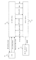
本実施形態の特徴点の理解を容易とするため、最初に、HDDの全体構成の概略を説明する。図1は、本実施の形態に係るHDD1の構成を模式的に示すブロック図である。図1に示すように、HDD1は、密閉されたエンクロージャ10内に、メディア(記録媒体)の一例である磁気ディスク11、ヘッドの一例であるヘッド素子部12、アーム電子回路(AE:Arm Electronics)13、スピンドル・モータ(SPM)14、ボイス・コイル・モータ(VCM)15、そしてアクチュエータ16を備えている。
In order to facilitate understanding of the feature points of this embodiment, first, an outline of the entire configuration of the HDD will be described. FIG. 1 is a block diagram schematically showing the configuration of the HDD 1 according to the present embodiment. As shown in FIG. 1, an HDD 1 includes a sealed
HDD1は、エンクロージャ10の外側に固定された回路基板20を備えている。回路基板20上には、リード・ライト・チャネル(R/Wチャネル)21、モータ・ドライバ・ユニット22、ハードディスク・コントローラ(HDC)とMPUの集積回路(以下、HDC/MPU)23及びRAM24などの各ICを備えている。尚、各回路構成は一つのICに集積すること、あるいは、複数のICに分けて実装することができる。
The HDD 1 includes a
外部ホスト51からのユーザ・データは、HDC/MPU23によって受信され、R/Wチャネル21、AE13を介して、ヘッド素子部12によって磁気ディスク11に書き込まれる。また、磁気ディスク11に記憶されているユーザ・データはヘッド素子部12によって読み出され、そのユーザ・データは、AE13、R/Wチャネル21を介して、HDC/MPU23から外部ホスト51に出力される。
User data from the
次に、HDD1の各構成要素について説明する。磁気ディスク11は、SPM14に固定されている。SPM14は所定の速度で磁気ディスク11を回転する。HDC/MPU23からの制御データに従って、モータ・ドライバ・ユニット22がSPM14を駆動する。本例の磁気ディスク11は、データを記録する記録面を両面に備え、各記録面に対応するヘッド素子部12が設けられている。
Next, each component of the HDD 1 will be described. The
各ヘッド素子部12はスライダ(不図示)に固定されている。また、スライダはアクチュエータ16の先端部に固定されている。アクチュエータ16はVCM15に連結され、回動軸を中心に揺動することによって、ヘッド素子部12(及びスライダ)を回転する磁気ディスク11上においてその半径方向に移動する。モータ・ドライバ・ユニット22は、HDC/MPU23からの制御データ(DACOUTと呼ぶ)に従ってVCM15を駆動する。
Each
ヘッド素子部12には、磁気ディスク11への記録データに応じて電気信号を磁界に変換するライト素子、及び磁気ディスク11からの磁界を電気信号に変換するリード素子を備えている。なお、磁気ディスク11は、1枚以上あればよく、記録面は磁気ディスク11の片面あるいは両面に形成することができる。
The
AE13は、複数のヘッド素子部12の中から磁気ディスク11へのアクセスを行う1つのヘッド素子部12を選択し、選択されたヘッド素子部12により再生される再生信号を一定のゲインで増幅(プリアンプ)し、R/Wチャネル21に送る。また、R/Wチャネル21からの記録信号を選択されたヘッド素子部12に送る。
The
R/Wチャネル21は、ホスト51にユーザ・データ転送する際には、リード処理を行う。リード処理において、R/Wチャネル21はAE13から供給されたリード信号を一定の振幅となるように増幅し、取得したリード信号からデータを抽出し、デコード処理を行う。読み出されるデータは、ユーザ・データとサーボ・データを含む。デコード処理されたリード・ユーザ・データは、HDC/MPU23に供給される。
The R /
また、R/Wチャネル21は、ホスト51から転送されたユーザ・データについてライト処理を実行する。R/Wチャネル21は、ライト処理を、HDC/MPU23からの制御信号に従って実行する。ライト処理において、R/Wチャネル21はHDC/MPU23から供給されたライト・データをコード変調し、更にコード変調されたライト・データをライト信号に変換してAE13に供給する。
Further, the R /
HDC/MPU23において、MPUはRAM24にロードされたコードに従って動作する。HDD1の起動に伴い、RAM24には、MPU上で動作するコードの他、制御及びデータ処理に必要とされるデータが磁気ディスク11あるいはROM(不図示)からロードされる。HDC/MPU23は、リード/ライト処理制御、コマンド実行順序の管理、サーボ信号を使用したヘッド素子部12のポジショニング制御(サーボ制御)、インターフェース制御、ディフェクト管理などのデータ処理に関する必要な処理の他、HDD1の全体制御を実行する。
In the HDC /
本形態において着目すべき点の一つは、HDC/MPU23によるライト処理制御における、磁気ディスク11に対するユーザ・データ書き込みの許否判定手法である。本形態のHDC/MPU23は、ライト処理において、サーボ・データに加えてユーザ・データの読み出し信号を使用して、磁気ディスク11へのユーザ・データの書き込み許否を判定する。これによって、サーボ・サンプリングにほぼ同期するアクチュエータ振動を検出し、オフトラック・ライトを防止する。この振動検出手法及びライト許否判定処理については後に詳述する。
One of the points to be noted in this embodiment is a method for determining whether or not to allow user data to be written to the
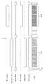
続いて、図2を参照して、磁気ディスク11上の記録データについて説明する。図2は、磁気ディスク11の記録面の記録データの状態を模式的に示している。図2に示されるように、磁気ディスク11の記録面には、磁気ディスク11の中心から半径方向に放射状に延び、所定の角度毎に離間して形成された複数のサーボ領域111と、隣り合う2つのサーボ領域111の間にデータ領域112が形成されている。サーボ領域111とデータ領域112は、所定の角度で交互に設けられている。各サーボ領域111には、ヘッド素子部12の位置決め制御を行うためのサーボ・データが記録される。各データ領域112には、ユーザ・データが記録される。
Next, recording data on the
磁気ディスク11の記録面には、半径方向に所定幅を有し、同心円状に形成された複数本のトラック113が形成される。サーボ・データおよびユーザ・データは、トラック113に沿って記録される。一つのトラック113は、サーボ領域111間に複数のデータ・セクタ(ユーザ・データの記録単位)を備えている。つまり、各トラック113は、互いに所定角度において離間して配置された複数のサーボ・データと、各サーボ・データの間に配置された複数のデータ・セクタとを含んでいる。また、本明細書においては、1トラックにおいて、一つのサーボ・データから、次のサーボ・データの直前のデータ・セクタまでを、一つのサーボ・セクタと称する。
A plurality of tracks 113 having a predetermined width in the radial direction and concentrically formed are formed on the recording surface of the
複数トラック113は、磁気ディスク11の半径方向の位置に従って、複数のゾーン114にグループ化されている。1つのトラック113に含まれるデータ・セクタの数は、ゾーンのそれぞれに設定される。図2においては、3つのゾーン114a−114cが例示されている。ゾーン毎に記録周波数を変更することで、磁気ディスク11全体の記録密度を向上することができる。
The plurality of tracks 113 are grouped into a plurality of zones 114 according to the positions in the radial direction of the
以下において、磁気ディスク11へのユーザ・データ・ライトの制御手法を説明する。上述のように、本形態のHDD1は、サーボ・データに加えて、データ・セクタ(ユーザ・データの読み出し信号振幅を使用してライト処理制御を行う。データ・セクタ読み出し信号を使用することによって、サーボ・サンプリングに同調したアクチュエータ振動を検出し、基準をこえる振動がある場合にはライト禁止(Write Inhibit)とする。これによって、サーボ信号で検出できないヘッド振動を検出し、それに起因するオフトラック・ライトを防止することができる。
Hereinafter, a method for controlling user data write to the
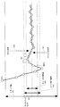
図3(a)は、ヘッド素子部12に含まれるリード素子121がトラック・フォローイングする様子を、模式的に示している。2つのサーボ・データ211a、211bの間における、リード素子121の移動の様子が示されている。サーボ・データ211a、211b間には、7つのデータ・セクタ212a−212gが記録されている。つまり、このトラックにおいて、1サーボ・セクタは、サーボ・データ211aと、7つのデータ・セクタ212a−212gとから構成されている。
FIG. 3A schematically shows a state in which the
リード素子121が、図3のようにサーボ・サンプリング周波数と同一周波数で、あるいはその整数倍の周波数で半径方向に振動する場合、リード素子121が読み出すサーボ信号は変化しないため、HDD1はサーボ信号によって、その振動を検出することができない。この状態で磁気ディスク11へのユーザ・データの書き込みを開始すると、オフトラック・ライトとなり、隣接トラックのユーザ・データに新たな別のユーザ・データが上書きされてしまう。
When the read
それに対して、データ・セクタ212の読み出し信号の振幅は、1サーボ・セクタ内における振動に従って変化する。データ・セクタの読み出し信号振幅を表す値の一つは、リード・バック信号振幅である。リード・バック信号振幅は、リード素子121がデータ・セクタ内のパターンを読み出した実際の信号振幅を表す値である。つまり、図3(b)に示すように、リード素子121のフォローイング・トラック・センタからの半径方向距離にたいして単調に減少するようにリード・バック信号振幅が変化する。
On the other hand, the amplitude of the read signal of the data sector 212 changes according to the vibration in one servo sector. One value representing the read signal amplitude of the data sector is the read back signal amplitude. The read back signal amplitude is a value representing the actual signal amplitude when the
従って、リード・バック信号振幅を使用することによって、アクチュエータ16、つまりヘッド素子部12の振動(ヘッド振動)を検出し、その振動が基準範囲外にあるときは磁気ディスク11へのデータ・ライトを禁止する。このように、ヘッド振動が基準範囲にあることを条件としてライトを許可することで、オフトラック・ライトを効果的に防止することができる。また、このヘッド振動はアクチュエータの機械的共振に起因するものであるので、時間の経過とともに減少する。従って、ヘッド振動が基準をこえる場合、HDD1は、アクチュエータの振動が小さくなるのを待って、ユーザ・データの磁気ディスク11への書き込みを開始する。
Therefore, by using the read-back signal amplitude, the vibration of the
本形態のHDD1は、ヘッド素子部12の振動を正確に検出するために、リード・バック信号振幅の変動を使用する。検出すべきであるのは、サーボ・データ間における機械的なヘッド振動であるので、この領域におけるリード・バック信号振幅の変動が問題となる。この変動が大きく基準値を超えている場合にはライトを禁止し、それが基準内にある場合にライトを許可する。
The HDD 1 of this embodiment uses fluctuations in the read-back signal amplitude in order to accurately detect the vibration of the
好ましくは、図3(b)に示すように、サーボ・セクタ211a、211b間におけるリード・バック信号エンベロープの最大値(MAX)と最小値(MIN)の差分を使用し、リード・バック信号振幅の変動の大きさを判定する。例えば、Δ=(MAX−MIN)と予め設定されている値とを比較して、ライトの許否を決定することができる。この他、MAX/MIN、(MAX−MIN)/MINなどの計算値を、ライト許否を決定するために使用することができる。なお、ノイズの影響を避けるため、例えば、規定範囲外の振幅を除いた中から振幅の最大値(MAX)を決定してもよい。
Preferably, as shown in FIG. 3B, the difference between the maximum value (MAX) and the minimum value (MIN) of the read back signal envelope between the
HDD1は、一つもしくは複数のサーボ・セクタにおけるリード・バック信号振幅の変動を使用して、ライトの許否を決定することができる。例えば、ユーザ・データを書き込むサーボ・セクタの直前のサーボ・セクタにおけるリード・バック信号振幅の変動を検出し、その大きさによってライトの許否を決定することができる。処理効率やパフォーマンスの点からは、単一のサーボ・セクタにおけるリード・バック信号振幅の変動から、ライト許否判定を行うことが好ましいだろう。 The HDD 1 can determine whether to permit writing by using fluctuations in the read back signal amplitude in one or a plurality of servo sectors. For example, it is possible to detect whether or not to permit writing based on the magnitude of the fluctuation of the read back signal amplitude in the servo sector immediately before the servo sector to which user data is written. From the viewpoint of processing efficiency and performance, it is preferable to perform the write permission / rejection determination from the fluctuation of the read back signal amplitude in a single servo sector.
あるいは、HDD1は、複数のサーボ・セクタのリード・バック信号振幅の変動を検出し、各変動の大きさが基準範囲内にあることを条件として、磁気ディスク11へのデータ・ライトを許可することができる。より正確な振動検出のためには、複数のサーボ・セクタにおけるリード・バック信号振幅の変動を使用することが好ましい。また、これら複数のサーボ・セクタは連続していることが好ましい。
Alternatively, the HDD 1 detects fluctuations in the read-back signal amplitude of a plurality of servo sectors, and permits data writing to the
なお、データ・セクタの読み出し信号振幅の変化は、例えば、R/Wチャネル12内部のVGA(Variable Gain Amplifier)ゲインから求めることもできる。VGAは、データ・セクタ内の一定周波数信号であるプリアンブルの振幅が一定となるようにゲイン調整する。HDD1は、そのゲインから各データ・セクタに対応するデータ・セクタの読み出し信号振幅を決定することができる。HDD1は、VGAゲインを使用してサーボ・セクタ211a、211b間の各データ・セクタ212a−212gのリード・バック信号振幅を検出し、その中の最大値(MAX)と最小値(MIN)から振幅変動の大きさを判定することができる。
The change in the read signal amplitude of the data sector can also be obtained from, for example, a VGA (Variable Gain Amplifier) gain in the R /
続いて、本実施形態のライト処理の全体フローを説明する。図4は、ライト処理における、ヘッド素子部12の移動に伴うサーボ信号の変化を示している。各円はヘッド位置を示しており、ヘッド位置は図の左から右に向かって変化している。ヘッド位置は、ヘッド素子部12(リード素子121)が読み出した位置信号の値(PES:Position Error Signal)で表すことができる。位置信号は、サーボ信号のアドレス・データとバーストから決定する。
Next, the overall flow of the write process of this embodiment will be described. FIG. 4 shows changes in the servo signal accompanying the movement of the
ライト処理において、ヘッド素子部12は、現在トラックから目標トラックへとシーク動作を行う。ヘッド素子部12は目標トラックのトラック幅411内に移動し、さらにシーク完了範囲内412に入る。その後、ヘッド素子部12はそのデータ・トラックのトラック・センタ413に沿ってフォローイングする。本形態のHDD1は、位置信号から決定されるヘッド位置、同様に位置信号から決定されるヘッド速さ、そしてリード・バック信号振幅から検出される機械振動のそれぞれが、各条件を満す場合に磁気ディスク11へのユーザ・データ・ライトを許可する。
In the write process, the
具体的には、第1の条件は、位置信号変化から求められるヘッド速さが基準値内であることである。さらに、位置信号の値が基準範囲としてのライト許可範囲414内にあることが第2の条件である。これら二つの条件は、複数の連続サーボ信号において満たしていることが必要とされる。図4は、4連続サーボ信号451が上記2つの条件を満たすことが必要とされる例を示している。 Specifically, the first condition is that the head speed obtained from the position signal change is within the reference value. Furthermore, the second condition is that the value of the position signal is within the write permission range 414 as the reference range. These two conditions are required to be satisfied in a plurality of continuous servo signals. FIG. 4 shows an example in which four continuous servo signals 451 are required to satisfy the above two conditions.
本例のHDD1は、さらに、データ・セクタのリード・バック信号振幅の変動が基準範囲内であることを、ライト許可の条件とする。図4の例においては、4つのサーボ信号451がヘッド位置とヘッド速さの既定条件を満たした後のタイミング421において、HDD1はヘッド振動について判定を行う。リード・バック信号振幅の変動が基準範囲内にある場合、その次のサーボ・セクタ422から先においてライトが許可される。
The HDD 1 of this example further sets a condition for permitting writing that the fluctuation of the read-back signal amplitude of the data sector is within the reference range. In the example of FIG. 4, the HDD 1 determines the head vibration at the
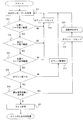
図5のフロー・チャート及び図4を参照して、上述のライト許否判定処理について具体的に説明する。ライト許否判定処理は、R/Wチャネル21から得られるデータを使用して、HDC/MPU23が実行する。ライト処理を開始すると、HDC/MPU23は、ヘッド素子部12の移動に従い各サーボ・データを取得する(S11)。具体的には、R/Wチャネル21は、ヘッド素子部12が読み出すサーボ信号からサーボ・データを抽出し、それをHDC/MPU23に転送する。
With reference to the flowchart of FIG. 5 and FIG. 4, the above-described write permission / refusal determination processing will be specifically described. The write permission / rejection determination process is executed by the HDC /
次に、HDC/MPU23は、各ヘッド位置(各位置信号)がシーク完了範囲412にあるかを判定する(S12)。ヘッド位置がシーク完了範囲412ではない場合、カウンタをリセットして(S13)次のサーボ・データを取得するステップ(S11)に戻る。カウンタは、図4で示したように、複数連続サーボ・データ451が規定条件を満たすことを判定するために使用する。ヘッド位置がシーク完了範囲412にある場合、HDC/MPU23はヘッド速さが基準範囲であるシーク完了範囲内であるかを判定する(S14)。
Next, the HDC /
ヘッド速さがシーク完了範囲ではない場合、カウンタをリセットして(S13)、次のサーボ・データを取得するステップ(S11)に戻る。ヘッド速さがシーク完了範囲にある場合、各ヘッド位置(各位置信号)がライト許可範囲414にあるかを判定する(S15)。ヘッド位置がライト許可範囲414ではない場合、カウンタをリセットして(S13)次のサーボ・データを取得するステップ(S11)に戻る。ヘッド位置がライト許可範囲414にある場合、HDC/MPU23はカウント数が基準値N(図4の例では3)をこえているか判定する(S16)。Nをこえていない場合、HDC/MPU23はカウント数をインクリメントし(S17)、次のサーボ・データ取得ステップ(S11)に戻る。
If the head speed is not within the seek completion range, the counter is reset (S13), and the process returns to the step (S11) for acquiring the next servo data. When the head speed is within the seek completion range, it is determined whether each head position (each position signal) is within the write permission range 414 (S15). If the head position is not within the write permission range 414, the counter is reset (S13), and the process returns to the step (S11) for acquiring the next servo data. If the head position is within the write permission range 414, the HDC /
カウント数が基準値Nをこえている場合(S16)、HDC/MPU23は、リード・バック信号振幅の変動が基準内にあるか否かを判定する(S18)。この判定は、上述の手法に従って行うことができ、例えば、Δ=(MAX−MIN)が基準値をこえていないことを許可の条件とする。振幅変動が基準内ではない場合(S18)、HDC/MPU23はカウンタをリセットし(S19)、その後、ヘッド素子部12の振動停止を待つ(S20)。具体的には、HDC/MPU23は予め定められた規定時間処理を停止した後、次のサーボ・データ取得ステップ(S11)からの処理を再開する。一方、リード・バック信号の振幅変動が基準内である場合(S18)、HDC/MPU23はライト許可の判定を行い(S21)、ターゲット・データ・セクタにおいてユーザ・データを書き込む。
If the count exceeds the reference value N (S16), the HDC /
上述の処理フローは、ヘッド位置とヘッド速さが規定条件を満たした直後の一つのサーボ・セクタにおける単一リード・バック信号の振幅変動からライト許否判定を行う。これと異なり、ヘッド位置とヘッド速さが規定条件を満たした後の複数サーボ・セクタの振幅変動を使用してライト許否判定をすることもできる。例えば、HDC/MPU23は別のカウンタを備え、連続する複数サーボ・セクタのリード・バック信号振幅の変動が、基準値以下である場合にライトを許可する。これによって、より正確な振動判定を行い、オフトラック・ライトをより確実に防止する。なお、この場合、ヘッド速さとヘッド位置判定のための複数サーボ・セクタに加えて、振動判定のために複数サーボ・セクタを要する。
In the processing flow described above, write permission / rejection determination is performed from the amplitude fluctuation of a single read back signal in one servo sector immediately after the head position and head speed satisfy the prescribed conditions. In contrast to this, it is also possible to make a write permission / rejection determination using amplitude fluctuations of a plurality of servo sectors after the head position and the head speed satisfy prescribed conditions. For example, the HDC /
図6のフロー・チャートは、他の好ましいライト許否判定処理フローを示している。このライト許否判定処理フローは、図5の例と異なり、ヘッド位置とヘッド速さの判定と共にヘッド振動の判定を行う。これによって、複数サーボ・セクタを使用して正確な振動判定を行うとともに、ライト許否判定のためのサーボ・セクタ数を低減してパフォーマンスの向上を図る。図5を参照して説明された処理フローとの違いは、この処理フローは、カウント数の判定ステップ(S16)の前に、振動判定ステップ(S18)を実行することである。 The flowchart of FIG. 6 shows another preferred write permission / rejection determination processing flow. Unlike the example of FIG. 5, the write permission / rejection determination process flow determines head vibration as well as head position and head speed. As a result, accurate vibration determination is performed using a plurality of servo sectors, and the number of servo sectors for write permission / rejection determination is reduced to improve performance. The difference from the processing flow described with reference to FIG. 5 is that this processing flow executes the vibration determination step (S18) before the count number determination step (S16).
つまり、HDC/MPU23は、ヘッド速さがシーク完了範囲にあり(S14)、ヘッド位置がライト許可範囲414にある(S15)場合に、さらに、そのサーボ・セクタ内のデータ・セクタのリード・バック信号振幅を取得し、その変動についての判定処理(S18)を実行する。その信号振幅変動が基準内である場合に、HDC/MPU23はカウンタをインクリメントする(S17)。リード・バック信号振幅変動が基準値をこえる場合、HDC/MPU23はカウンタをリセットし(S19)、ヘッド振動の停止を待って(S20)、次のサーボ・データ取得ステップ(S11)からの処理を繰り返す。
That is, when the head speed is in the seek completion range (S14) and the head position is in the write permission range 414 (S15), the HDC /
このように、サーボ信号を使用したヘッド速さ及びヘッド位置の判定処理(S13−S15)と共に、そのサーボ信号と同一サーボ・セクタについて、データ・セクタ読み出し信号を使用したヘッド振動判定処理(S18)を行うことによって、複数サーボ・セクタについて振動判定処理行う場合にも効率的な判定処理が可能であり、パフォーマンスの低下を抑制することができる。 As described above, the head speed and head position determination processing using the servo signal (S13-S15) and the head vibration determination processing using the data sector read signal for the same servo sector as the servo signal (S18). By performing the above, efficient determination processing can be performed even when vibration determination processing is performed for a plurality of servo sectors, and deterioration in performance can be suppressed.
次に、ライト許否判定処理における、HDD1内の信号処理について具体的に説明する。上述のように、HDC/MPU23がR/Wチャネル21からのデータを使用してライト許否判定処理を実行する。図7は、HDC/MPU23、R/Wチャネル21及びAE13間の各伝送信号を示している。図8は、それら信号のタイミング・チャートである。なお、このタイミング・チャートは各信号の変化を模式的に示すものであって、実際のHDDにおけるタイミングを正確に反映するものではない。s図7及び8においては、ヘッド振動判定処理及びライトが許可判定されたサーボ・セクタの次のサーボ・セクタにおいて、ユーザ・データを書き込む処理例が示されている。
Next, signal processing in the HDD 1 in the write permission / rejection determination process will be specifically described. As described above, the HDC /
図7に示すように、HDC/MPU23は、R/Wチャネル21に対してライト・ゲート信号(Write_Gate)、リード・ゲート信号(Read_Gate)及びサーボ・ゲート信号(Servo_Gate)の各制御信号を出力する。ライト・ゲート信号(Write_Gate)は磁気ディスク11へのユーザ・データの書き込みを制御する信号であり、リード・ゲート信号(Read_Gate)は磁気ディスク11からのユーザ・データの読み出しを制御する信号であり、サーボ・ゲート信号(Servo_Gate)は磁気ディスク11からのサーボ・データの読み出しを制御する信号である。
As shown in FIG. 7, the HDC /
AE13が増幅したサーボ・データ信号(Servo_Data_Signal)とリード・ユーザ・データ信号(Read_User_Data_Signal)とは、R/Wチャネル21に転送される。R/Wチャネル21は、サーボ・データ信号(Servo_Data_Signal)からサーボ・データ(Servo_Data)を生成し、HDC/MPU23に転送する。HDC/MPU23は、サーボ・データから、ヘッド位置制御のために、VCM15制御信号であるDACOUTを生成し、モータ・ドライバ・ユニット22へ出力する。
The servo data signal (Servo_Data_Signal) and the read user data signal (Read_User_Data_Signal) amplified by the
さらに、R/Wチャネル21は、AE13から転送されたリード・ユーザ・データ信号(Read_User_Data_Signal)から、対応サーボ・セクタにおけるリード・バック信号振幅の最大値(MAX)と最小値(MIN)を特定し、R/Wチャネル21内のレジスタ(不図示)に格納する。HDC/MPU23は、ヘッド振動判定のタイミングにおいて、それらの値(MAX、MIN)をレジスタから取得する。磁気ディスク11へのデータ書き込みにおいては、HDC/MPU23からライト・データ(Write_Data)がR/Wチャネル21へ転送され、R/Wチャネル21はそのデータからライト・データ信号(Write_Data_Signal)を生成し、AE13に出力する。
Further, the R /
図8に示すように、サーボ・ゲート信号(Servo_Gate)がLOW(Asssert)であるときに、磁気ディスク11からサーボ・データ(Servo_Data)211がよみだされる。また、ライト・ゲート信号(Write_Gate)がLOW(Asssert)であるときに、磁気ディスク11へライト・データ(Write_Data)が書き込まれる。さらに、本形態のHDD1においては、ヘッド振動判定を行うため、リード・ゲート信号(Read_Gate)がLOW(Asssert)であるときに、磁気ディスク11からユーザ・データ(Read_User_Data)212が読みだされる。
As shown in FIG. 8, when the servo gate signal (Servo_Gate) is LOW (Asssert), servo data (Servo_Data) 211 is read from the
図8の例において、HDC/MPU23は、矢印のタイミングにおいて、データ・セクタ212rのリード・バック信号振幅の最大値MAXと最小値MINを使用してライト許否を判定する。なお、このタイミングの前において、HDC/MPU23は、サーボ・データから、ヘッド速さとヘッド位置とが規定条件を満足していることをすでに判定している。本例においては、ヘッド振動が許容範囲内であるため、すぐ次のサーボ・セクタにおける各ターゲット・データ・セクタ212wに、ライト・データを書き込む。
In the example of FIG. 8, the HDC /
以上、本発明を好ましい実施形態を例として説明したが、本発明が上記の実施形態に限定されるものではない。当業者であれば、上記の実施形態の各要素を、本発明の範囲において容易に変更、追加、変換することが可能である。例えば、1サーボ・セクタ内のリード・バック信号変動ではなく、複数サーボ・セクタ間のリード・バック信号の変動を使用してライト許否の決定を行うことも可能である。また、本発明はHDDに限らず、他のタイプのメディアを使用するデータ記憶装置に適用することができる。 As mentioned above, although this invention was demonstrated taking preferable embodiment as an example, this invention is not limited to said embodiment. A person skilled in the art can easily change, add, and convert each element of the above-described embodiment within the scope of the present invention. For example, it is possible to determine whether or not to permit writing by using fluctuations in the read-back signal among a plurality of servo sectors instead of fluctuations in the read-back signal within one servo sector. The present invention is not limited to the HDD, and can be applied to a data storage device that uses other types of media.
1 ハードディスク・ドライブ、10 エンクロージャ、11 磁気ディスク
12 ヘッド素子部、14 スピンドル・モータ、15 ボイス・コイル・モータ
16 アクチュエータ、20 回路基板、21 リード・ライト・チャネル
22 モータ・ドライバ・ユニット、23 ハードディスクコントローラ/MPU
51 ホスト、111 サーボ領域、112 データ領域、113 トラック
211 サーボ・データ、212 データ・セクタ
DESCRIPTION OF SYMBOLS 1 Hard disk drive, 10 Enclosure, 11
51 Host, 111 Servo area, 112 Data area, 113
Claims (14)
回転するメディア上で、前記サーボ・データから決定されるヘッドの位置信号を使用して、前記ヘッドをユーザ・データ書き込みのターゲット・トラックに位置決めし、
前記ターゲット・トラックのデータ・セクタを前記ヘッドで読み出し、
前記位置信号の値が基準範囲としてのライト許可範囲にある場合において、前記データ・セクタの読み出し信号の変動における最大値と最小値を検出し、該最大値と最小値の差が基準値を超えるか否かによって前記メディアへのデータ書き込み許否を決定する、方法。 A method for controlling the writing of user data to a medium having a plurality of servo data spaced apart in the circumferential direction in each track and a data sector located between the servo data,
On rotating media, using the position signal of the head determined from the servo data, and positioning the head to a target track of the user data writing,
Read the data sector of the target track with the head,
When the value of the position signal is within the write permission range as a reference range, the maximum value and the minimum value in the fluctuation of the read signal of the data sector are detected, and the difference between the maximum value and the minimum value exceeds the reference value A method for determining whether or not data writing to the medium is permitted depending on whether or not the data is written.
回転するメディアからサーボ・データとデータ・セクタとを読み出すヘッドと、
読み出されたサーボ・データを使用して、ユーザ・データを書き込むターゲット・トラックに前記ヘッドを位置決め制御するコントローラと、を備え、
前記コントローラは、前記ヘッドの位置がライト許可範囲にある場合の前記データ・セクタの読み出し信号の変動における最大値と最小値を検出し、該最大値と最小値の差が基準値を超えるか否かによって、前記メディアへのデータ書き込み許否を決定する、
データ記憶装置。 A data storage device for writing user data to a medium having a plurality of servo data spaced apart in the circumferential direction in each track and a data sector located between each servo data. ,
A head that reads servo data and data sectors from the rotating media;
A controller for controlling the positioning of the head on a target track to which user data is written using the read servo data, and
The controller detects a maximum value and a minimum value in fluctuations in the read signal of the data sector when the position of the head is within a write permission range , and whether or not a difference between the maximum value and the minimum value exceeds a reference value To determine whether or not to write data to the medium.
Data storage device.
回転するメディア上で、前記サーボ・データから決定されるヘッドの位置信号を使用して、前記ヘッドをユーザ・データ書き込みのターゲット・トラックに位置決めし、 On the rotating media, using the head position signal determined from the servo data, the head is positioned on a target track for writing user data,
前記ターゲット・トラックのデータ・セクタを前記ヘッドで読み出し、 Read the data sector of the target track with the head,
前記位置信号の値が基準範囲としてのライト許可範囲にある場合において、前記データ・セクタの読み出し信号の変動における最大値と最小値を検出し、該最大値と最小値の比が基準値を超えるか否かによって前記メディアへのデータ書き込み許否を決定する、方法。 When the value of the position signal is within the write permission range as the reference range, the maximum value and the minimum value in the fluctuation of the read signal of the data sector are detected, and the ratio between the maximum value and the minimum value exceeds the reference value A method for determining whether or not data writing to the medium is permitted depending on whether or not the data is written.
回転するメディア上で、前記サーボ・データから決定されるヘッドの位置信号を使用して、前記ヘッドをユーザ・データ書き込みのターゲット・トラックに位置決めし、 On the rotating media, using the head position signal determined from the servo data, the head is positioned on a target track for writing user data,
前記ターゲット・トラックのデータ・セクタを前記ヘッドで読み出し、 Read the data sector of the target track with the head,
前記位置信号の値が基準範囲としてのライト許可範囲にある場合において、前記データ・セクタの読み出し信号の変動における最大値と最小値を検出し、該最大値と最小値の差と、最小値との比が基準値を超えるか否かによって前記メディアへのデータ書き込み許否を決定する、方法。 When the value of the position signal is within the write permission range as a reference range, the maximum value and the minimum value in the fluctuation of the read signal of the data sector are detected, the difference between the maximum value and the minimum value, the minimum value, A method for determining whether or not data writing to the medium is permitted depending on whether or not the ratio exceeds a reference value.
Priority Applications (6)
| Application Number | Priority Date | Filing Date | Title |
|---|---|---|---|
| JP2005243056A JP5064666B2 (en) | 2005-08-24 | 2005-08-24 | Data storage device and user data write control method thereof |
| EP06012892A EP1758114A3 (en) | 2005-08-24 | 2006-06-22 | Data storage device and a method of controlling write of user data thereof |
| TW095124746A TW200731235A (en) | 2005-08-24 | 2006-07-07 | Data storage device and a method of controlling write of user data thereof |
| SG200604677-5A SG130092A1 (en) | 2005-08-24 | 2006-07-11 | Data storage device and a method of controlling write of user data thereof |
| CNB200610121623XA CN100550164C (en) | 2005-08-24 | 2006-08-23 | Data storage device and control the method that its user data writes |
| US11/509,117 US7426086B2 (en) | 2005-08-24 | 2006-08-23 | Off track write protection for data storage device |
Applications Claiming Priority (1)
| Application Number | Priority Date | Filing Date | Title |
|---|---|---|---|
| JP2005243056A JP5064666B2 (en) | 2005-08-24 | 2005-08-24 | Data storage device and user data write control method thereof |
Publications (3)
| Publication Number | Publication Date |
|---|---|
| JP2007058988A JP2007058988A (en) | 2007-03-08 |
| JP2007058988A5 JP2007058988A5 (en) | 2008-09-11 |
| JP5064666B2 true JP5064666B2 (en) | 2012-10-31 |
Family
ID=37461362
Family Applications (1)
| Application Number | Title | Priority Date | Filing Date |
|---|---|---|---|
| JP2005243056A Expired - Fee Related JP5064666B2 (en) | 2005-08-24 | 2005-08-24 | Data storage device and user data write control method thereof |
Country Status (6)
| Country | Link |
|---|---|
| US (1) | US7426086B2 (en) |
| EP (1) | EP1758114A3 (en) |
| JP (1) | JP5064666B2 (en) |
| CN (1) | CN100550164C (en) |
| SG (1) | SG130092A1 (en) |
| TW (1) | TW200731235A (en) |
Families Citing this family (4)
| Publication number | Priority date | Publication date | Assignee | Title |
|---|---|---|---|---|
| US9355667B1 (en) * | 2014-11-11 | 2016-05-31 | Western Digital Technologies, Inc. | Data storage device saving absolute position at each servo wedge for previous write operations |
| US9236087B1 (en) * | 2014-11-12 | 2016-01-12 | Seagate Technology Llc | Off-track prediction using an adaptive threshold |
| US9177582B1 (en) * | 2015-01-30 | 2015-11-03 | Kabushiki Kaisha Toshiba | Magnetic disk apparatus and off-tracking detection method |
| US9412403B1 (en) | 2015-08-25 | 2016-08-09 | HGST Netherlands B.V. | Magnetic recording disk drive with position error signal (PES) blocks in the data tracks for compensation of track misregistration |
Family Cites Families (8)
| Publication number | Priority date | Publication date | Assignee | Title |
|---|---|---|---|---|
| JP2923907B2 (en) * | 1996-05-30 | 1999-07-26 | 日本電気株式会社 | Magnetic disk drive |
| JP3721255B2 (en) * | 1998-01-13 | 2005-11-30 | 株式会社日立グローバルストレージテクノロジーズ | Magnetic information storage device |
| JP2000132933A (en) * | 1998-10-22 | 2000-05-12 | Internatl Business Mach Corp <Ibm> | Data writing control method of head and memory device utilizing the same |
| US6643084B1 (en) * | 2000-04-20 | 2003-11-04 | Hitachi Global Storage Technologies Netherlands B.V. | Adaptive off-track recovery |
| JP2002216443A (en) * | 2000-11-17 | 2002-08-02 | Hitachi Ltd | Magnetic disk device and control method therefor |
| JP2002269734A (en) * | 2001-03-14 | 2002-09-20 | Fuji Electric Co Ltd | Device for evaluating magnetic disk medium |
| JP2003338146A (en) * | 2002-05-20 | 2003-11-28 | Matsushita Electric Ind Co Ltd | Disk device and information recording medium |
| JP2006252593A (en) * | 2005-03-08 | 2006-09-21 | Hitachi Global Storage Technologies Netherlands Bv | Magnetic disk device, control method and manufacturing method thereof |
-
2005
- 2005-08-24 JP JP2005243056A patent/JP5064666B2/en not_active Expired - Fee Related
-
2006
- 2006-06-22 EP EP06012892A patent/EP1758114A3/en not_active Withdrawn
- 2006-07-07 TW TW095124746A patent/TW200731235A/en unknown
- 2006-07-11 SG SG200604677-5A patent/SG130092A1/en unknown
- 2006-08-23 US US11/509,117 patent/US7426086B2/en not_active Expired - Fee Related
- 2006-08-23 CN CNB200610121623XA patent/CN100550164C/en not_active Expired - Fee Related
Also Published As
| Publication number | Publication date |
|---|---|
| SG130092A1 (en) | 2007-03-20 |
| US20070047134A1 (en) | 2007-03-01 |
| TW200731235A (en) | 2007-08-16 |
| CN100550164C (en) | 2009-10-14 |
| US7426086B2 (en) | 2008-09-16 |
| EP1758114A3 (en) | 2010-03-10 |
| JP2007058988A (en) | 2007-03-08 |
| CN1920993A (en) | 2007-02-28 |
| EP1758114A2 (en) | 2007-02-28 |
Similar Documents
| Publication | Publication Date | Title |
|---|---|---|
| JP2008243269A (en) | Disk driving device and data rewriting method thereof | |
| JP2008192263A (en) | Disk drive apparatus and its error recovery method | |
| JP2006221733A (en) | Data storage device and its control method | |
| JP2007184023A (en) | Disk drive and its control method | |
| JP2006185583A (en) | Recording method of servo pattern of magnetic disk, and disk drive, magnetic disk and computer-readable medium utilizing the same | |
| JP2006185504A (en) | Data storage device and its control method | |
| JP5064666B2 (en) | Data storage device and user data write control method thereof | |
| JP2003045120A (en) | Disk storage device and reading method to be applied to the same device | |
| US7570446B2 (en) | Disk drive with improved format efficiency and control method thereof | |
| US20070247738A1 (en) | Write-once type storage apparatus, control method and record control circuit | |
| US7532426B2 (en) | Method for erase process on recording surface of disk and disk drive apparatus | |
| JP2006221732A (en) | Data storage device and its control method | |
| JP2005209281A (en) | Data storage device, control method for storage device and magnetic disk driving device | |
| US8125729B2 (en) | Disk drive and error-recovery processing method | |
| EP1585126B1 (en) | Data read retry with read timing adjustment for eccentricity of a disc in a data storage device | |
| JP4234530B2 (en) | Servo information writing method that reduces the influence of side fringes | |
| KR100468716B1 (en) | Dummy writing method and apparatus for improving a performance in a data storage system | |
| JP2007213745A (en) | Disk drive device | |
| KR20070023514A (en) | Data storage device and a method of controlling write of user data thereof | |
| JP2007287252A (en) | Erasure method of disk recording surface | |
| JP4739027B2 (en) | Data storage device and defect area management method thereof | |
| JP2007220204A (en) | Testing method of disk drive | |
| KR100459721B1 (en) | Method for reading data and control system using controllable dummy read gate | |
| JP2004095010A (en) | Disk drive and control method based on its environment temperature | |
| JP2008021351A (en) | Method for reassigning sector on media, and data storage |
Legal Events
| Date | Code | Title | Description |
|---|---|---|---|
| A521 | Written amendment |
Free format text: JAPANESE INTERMEDIATE CODE: A523 Effective date: 20080728 |
|
| A621 | Written request for application examination |
Free format text: JAPANESE INTERMEDIATE CODE: A621 Effective date: 20080728 |
|
| RD04 | Notification of resignation of power of attorney |
Free format text: JAPANESE INTERMEDIATE CODE: A7424 Effective date: 20100510 |
|
| A977 | Report on retrieval |
Free format text: JAPANESE INTERMEDIATE CODE: A971007 Effective date: 20100723 |
|
| A131 | Notification of reasons for refusal |
Free format text: JAPANESE INTERMEDIATE CODE: A131 Effective date: 20100817 |
|
| A601 | Written request for extension of time |
Free format text: JAPANESE INTERMEDIATE CODE: A601 Effective date: 20101104 |
|
| A602 | Written permission of extension of time |
Free format text: JAPANESE INTERMEDIATE CODE: A602 Effective date: 20101109 |
|
| A521 | Written amendment |
Free format text: JAPANESE INTERMEDIATE CODE: A523 Effective date: 20101216 |
|
| A02 | Decision of refusal |
Free format text: JAPANESE INTERMEDIATE CODE: A02 Effective date: 20110802 |
|
| A521 | Written amendment |
Free format text: JAPANESE INTERMEDIATE CODE: A523 Effective date: 20111026 |
|
| A911 | Transfer of reconsideration by examiner before appeal (zenchi) |
Free format text: JAPANESE INTERMEDIATE CODE: A911 Effective date: 20111104 |
|
| A912 | Removal of reconsideration by examiner before appeal (zenchi) |
Free format text: JAPANESE INTERMEDIATE CODE: A912 Effective date: 20111202 |
|
| A521 | Written amendment |
Free format text: JAPANESE INTERMEDIATE CODE: A523 Effective date: 20120712 |
|
| A01 | Written decision to grant a patent or to grant a registration (utility model) |
Free format text: JAPANESE INTERMEDIATE CODE: A01 |
|
| A61 | First payment of annual fees (during grant procedure) |
Free format text: JAPANESE INTERMEDIATE CODE: A61 Effective date: 20120809 |
|
| R150 | Certificate of patent or registration of utility model |
Free format text: JAPANESE INTERMEDIATE CODE: R150 |
|
| FPAY | Renewal fee payment (event date is renewal date of database) |
Free format text: PAYMENT UNTIL: 20150817 Year of fee payment: 3 |
|
| LAPS | Cancellation because of no payment of annual fees |