JP2006252593A - Magnetic disk device, control method and manufacturing method thereof - Google Patents
Magnetic disk device, control method and manufacturing method thereof Download PDFInfo
- Publication number
- JP2006252593A JP2006252593A JP2005063419A JP2005063419A JP2006252593A JP 2006252593 A JP2006252593 A JP 2006252593A JP 2005063419 A JP2005063419 A JP 2005063419A JP 2005063419 A JP2005063419 A JP 2005063419A JP 2006252593 A JP2006252593 A JP 2006252593A
- Authority
- JP
- Japan
- Prior art keywords
- flying height
- head
- protrusion
- magnetic disk
- magnetic head
- Prior art date
- Legal status (The legal status is an assumption and is not a legal conclusion. Google has not performed a legal analysis and makes no representation as to the accuracy of the status listed.)
- Withdrawn
Links
- 238000000034 method Methods 0.000 title claims description 51
- 238000004519 manufacturing process Methods 0.000 title claims description 10
- 230000007246 mechanism Effects 0.000 claims description 41
- 230000007547 defect Effects 0.000 claims description 12
- 238000012360 testing method Methods 0.000 claims description 5
- 230000002950 deficient Effects 0.000 claims description 4
- 238000010977 unit operation Methods 0.000 claims description 4
- 230000001419 dependent effect Effects 0.000 claims description 2
- 230000008034 disappearance Effects 0.000 claims 1
- 238000007689 inspection Methods 0.000 description 21
- 238000001514 detection method Methods 0.000 description 19
- 230000008859 change Effects 0.000 description 13
- 238000012937 correction Methods 0.000 description 11
- 230000008569 process Effects 0.000 description 11
- 230000004044 response Effects 0.000 description 10
- 238000010586 diagram Methods 0.000 description 7
- 239000010408 film Substances 0.000 description 7
- 238000006243 chemical reaction Methods 0.000 description 4
- 230000000694 effects Effects 0.000 description 4
- 238000012545 processing Methods 0.000 description 4
- 230000007274 generation of a signal involved in cell-cell signaling Effects 0.000 description 3
- 230000001939 inductive effect Effects 0.000 description 3
- 238000005070 sampling Methods 0.000 description 3
- 230000003321 amplification Effects 0.000 description 2
- 230000000712 assembly Effects 0.000 description 2
- 238000000429 assembly Methods 0.000 description 2
- 238000004364 calculation method Methods 0.000 description 2
- 239000004020 conductor Substances 0.000 description 2
- WABPQHHGFIMREM-UHFFFAOYSA-N lead(0) Chemical compound [Pb] WABPQHHGFIMREM-UHFFFAOYSA-N 0.000 description 2
- 230000005381 magnetic domain Effects 0.000 description 2
- 238000003199 nucleic acid amplification method Methods 0.000 description 2
- 230000002093 peripheral effect Effects 0.000 description 2
- 238000003825 pressing Methods 0.000 description 2
- 230000035945 sensitivity Effects 0.000 description 2
- 238000003860 storage Methods 0.000 description 2
- 239000010409 thin film Substances 0.000 description 2
- 238000007476 Maximum Likelihood Methods 0.000 description 1
- RTAQQCXQSZGOHL-UHFFFAOYSA-N Titanium Chemical compound [Ti] RTAQQCXQSZGOHL-UHFFFAOYSA-N 0.000 description 1
- HCHKCACWOHOZIP-UHFFFAOYSA-N Zinc Chemical compound [Zn] HCHKCACWOHOZIP-UHFFFAOYSA-N 0.000 description 1
- 230000001133 acceleration Effects 0.000 description 1
- 238000013459 approach Methods 0.000 description 1
- 230000001174 ascending effect Effects 0.000 description 1
- 238000004891 communication Methods 0.000 description 1
- 239000002131 composite material Substances 0.000 description 1
- 230000008602 contraction Effects 0.000 description 1
- 230000003247 decreasing effect Effects 0.000 description 1
- 230000004069 differentiation Effects 0.000 description 1
- 238000006073 displacement reaction Methods 0.000 description 1
- 239000012634 fragment Substances 0.000 description 1
- 230000005415 magnetization Effects 0.000 description 1
- 238000005259 measurement Methods 0.000 description 1
- 239000002245 particle Substances 0.000 description 1
- 238000007781 pre-processing Methods 0.000 description 1
- 230000008929 regeneration Effects 0.000 description 1
- 238000011069 regeneration method Methods 0.000 description 1
- 239000004065 semiconductor Substances 0.000 description 1
- 238000004088 simulation Methods 0.000 description 1
- 229910001220 stainless steel Inorganic materials 0.000 description 1
- 239000010935 stainless steel Substances 0.000 description 1
- 239000000725 suspension Substances 0.000 description 1
- 238000012546 transfer Methods 0.000 description 1
- 230000007704 transition Effects 0.000 description 1
- 239000011701 zinc Substances 0.000 description 1
- 229910052725 zinc Inorganic materials 0.000 description 1
- 229910052845 zircon Inorganic materials 0.000 description 1
- GFQYVLUOOAAOGM-UHFFFAOYSA-N zirconium(iv) silicate Chemical compound [Zr+4].[O-][Si]([O-])([O-])[O-] GFQYVLUOOAAOGM-UHFFFAOYSA-N 0.000 description 1
Images


Classifications
-
- G—PHYSICS
- G11—INFORMATION STORAGE
- G11B—INFORMATION STORAGE BASED ON RELATIVE MOVEMENT BETWEEN RECORD CARRIER AND TRANSDUCER
- G11B5/00—Recording by magnetisation or demagnetisation of a record carrier; Reproducing by magnetic means; Record carriers therefor
- G11B5/127—Structure or manufacture of heads, e.g. inductive
- G11B5/31—Structure or manufacture of heads, e.g. inductive using thin films
- G11B5/3109—Details
- G11B5/313—Disposition of layers
- G11B5/3133—Disposition of layers including layers not usually being a part of the electromagnetic transducer structure and providing additional features, e.g. for improving heat radiation, reduction of power dissipation, adaptations for measurement or indication of gap depth or other properties of the structure
- G11B5/3136—Disposition of layers including layers not usually being a part of the electromagnetic transducer structure and providing additional features, e.g. for improving heat radiation, reduction of power dissipation, adaptations for measurement or indication of gap depth or other properties of the structure for reducing the pole-tip-protrusion at the head transducing surface, e.g. caused by thermal expansion of dissimilar materials
-
- G—PHYSICS
- G11—INFORMATION STORAGE
- G11B—INFORMATION STORAGE BASED ON RELATIVE MOVEMENT BETWEEN RECORD CARRIER AND TRANSDUCER
- G11B5/00—Recording by magnetisation or demagnetisation of a record carrier; Reproducing by magnetic means; Record carriers therefor
- G11B5/40—Protective measures on heads, e.g. against excessive temperature
-
- G—PHYSICS
- G11—INFORMATION STORAGE
- G11B—INFORMATION STORAGE BASED ON RELATIVE MOVEMENT BETWEEN RECORD CARRIER AND TRANSDUCER
- G11B5/00—Recording by magnetisation or demagnetisation of a record carrier; Reproducing by magnetic means; Record carriers therefor
- G11B5/48—Disposition or mounting of heads or head supports relative to record carriers ; arrangements of heads, e.g. for scanning the record carrier to increase the relative speed
- G11B5/58—Disposition or mounting of heads or head supports relative to record carriers ; arrangements of heads, e.g. for scanning the record carrier to increase the relative speed with provision for moving the head for the purpose of maintaining alignment of the head relative to the record carrier during transducing operation, e.g. to compensate for surface irregularities of the latter or for track following
- G11B5/60—Fluid-dynamic spacing of heads from record-carriers
- G11B5/6005—Specially adapted for spacing from a rotating disc using a fluid cushion
-
- G—PHYSICS
- G11—INFORMATION STORAGE
- G11B—INFORMATION STORAGE BASED ON RELATIVE MOVEMENT BETWEEN RECORD CARRIER AND TRANSDUCER
- G11B5/00—Recording by magnetisation or demagnetisation of a record carrier; Reproducing by magnetic means; Record carriers therefor
- G11B5/48—Disposition or mounting of heads or head supports relative to record carriers ; arrangements of heads, e.g. for scanning the record carrier to increase the relative speed
- G11B5/4806—Disposition or mounting of heads or head supports relative to record carriers ; arrangements of heads, e.g. for scanning the record carrier to increase the relative speed specially adapted for disk drive assemblies, e.g. assembly prior to operation, hard or flexible disk drives
- G11B5/4873—Disposition or mounting of heads or head supports relative to record carriers ; arrangements of heads, e.g. for scanning the record carrier to increase the relative speed specially adapted for disk drive assemblies, e.g. assembly prior to operation, hard or flexible disk drives the arm comprising piezoelectric or other actuators for adjustment of the arm
Abstract
Description
本発明は、磁気ディスク装置において磁気ディスク表面に存在する突起物と磁気ヘッドとの衝突を回避するために磁気ヘッドのフライング・ハイトを制御する技術に関する。 The present invention relates to a technique for controlling a flying height of a magnetic head in order to avoid a collision between a protrusion on a surface of a magnetic disk and a magnetic head in a magnetic disk device.
磁気ディスク装置では、磁気ヘッドを備えるヘッド/スライダが、回転する磁気ディスク上を僅かの間隔を空けて浮上している。磁気ヘッドは、一般に誘導型の薄膜記録ヘッドとMR(磁気抵抗効果)素子を採用したMR再生ヘッドからなる複合型磁気ヘッドとして構成され両者は同一スライダに形成されている。磁気ヘッドと磁気ディスク表面との間隔をフライング・ハイトという。記録密度を向上するには、磁気ヘッドのフライング・ハイトをできるだけ低くして磁性層の粒子が発生する磁界の変化を検出する感度を高めたり、記録する磁化パターンを小さくしたりする必要がある。 In a magnetic disk device, a head / slider provided with a magnetic head floats on a rotating magnetic disk with a slight gap. The magnetic head is generally configured as a composite magnetic head composed of an inductive thin film recording head and an MR reproducing head employing an MR (magnetoresistance effect) element, and both are formed on the same slider. The distance between the magnetic head and the magnetic disk surface is called flying height. In order to improve the recording density, it is necessary to reduce the flying height of the magnetic head as much as possible to increase the sensitivity of detecting a change in the magnetic field generated by the magnetic layer particles, or to reduce the magnetization pattern to be recorded.
MR再生ヘッドは、外部磁界により生じる抵抗の変化をMR素子に流した電流の変化によって電圧として検出するもので、誘導型の再生ヘッドに比べて高い検出感度を得ることができる。一方、磁気ディスクの製造工程において磁気ディスクの表面を完全に平坦にすることは困難であり多少の突起物が残る。フライング・ハイトが低くなるほど、MR再生ヘッドとこの突起物が接触する頻度が増大する。MR素子は、MR再生ヘッドが突起物に接触したときに発生する熱エネルギーによりその温度係数に応じて抵抗が変化し、再生信号にゆらぎを生じて正確な再生動作をすることができなくなる。この現象は、サーマル・アスペリティ(以後、TA(Thermal Asperity)という。)として知られている。 The MR read head detects a change in resistance caused by an external magnetic field as a voltage based on a change in current passed through the MR element, and can provide higher detection sensitivity than an inductive read head. On the other hand, it is difficult to completely flatten the surface of the magnetic disk in the manufacturing process of the magnetic disk, and some protrusions remain. The lower the flying height, the greater the frequency with which the MR read head contacts this projection. In the MR element, the resistance changes according to the temperature coefficient due to the thermal energy generated when the MR read head comes into contact with the protrusion, and the read signal fluctuates, making it impossible to perform an accurate read operation. This phenomenon is known as thermal asperity (hereinafter referred to as TA (Thermal Asperity)).
また、記録動作中に記録ヘッドが磁気ディスク表面の突起物に接触した場合には、ヘッド/スライダの浮上姿勢が不安定になってサーボ制御に対する外乱要因となる。記録時には記録ヘッドが目標トラックに隣接したトラックに書き込んだり、書き込みエラーが発生したりすることを防止するためにサーボ制御が安定するまで記録動作を開始しないため、突起物との接触が発生するとセトリング・タイムが増大する。さらに記録ヘッドや再生ヘッドが頻繁に突起物に接触するとそれらの寿命が短縮したり、突起物の破片が磁気ディスク表面の他の場所に飛び火して突起物の数が増大したりするという問題もある。 Further, when the recording head comes into contact with the projection on the surface of the magnetic disk during the recording operation, the flying posture of the head / slider becomes unstable and becomes a disturbance factor for servo control. During recording, the recording head does not start writing to a track adjacent to the target track or a write error occurs, so the recording operation does not start until servo control is stabilized.・ Time increases. Furthermore, if the recording head or the reproducing head frequently contacts the projections, their lifetimes are shortened, and fragments of the projections jump to other places on the surface of the magnetic disk and the number of projections increases.
特許文献1に記載する発明は、加工バラツキや気圧差などに対応するために設けた浮上量マージンを除去するために、ヘッド/スライダに設けた圧電素子とTAを利用して適正シフト量見積もり処理を行って圧電素子の制御量を決めている(0041、0042)。そして最内周位置および最外周位置において適正シフト見積もり処理を行って、両位置における圧電素子に対する適正印加電圧をメモリに記憶しておく。実際の読み書き時は電圧を印加しない高浮上状態のままサーボ情報を読み取りつつ目的トラック径まで磁気ヘッド/スライダを移動させたあと、あらかじめメモリに記憶してある両適正印加電圧を用いて線形補完することにより決定した電圧を圧電素子に印加する(0045)。
In the invention described in
特許文献2に記載する発明は、TAを利用して磁気ディスクと磁気ヘッドとの磁気的スペーシングを検出し、ピエゾ素子を組み込んだアクチュエータで磁気的スペーシングを一定にする(0016)。そして、ピエゾ素子を利用したアクチュエータで磁気ディスク上に存在する突起に追従させる旨の記載がある。 In the invention described in Patent Document 2, the magnetic spacing between the magnetic disk and the magnetic head is detected using TA, and the magnetic spacing is made constant by an actuator incorporating a piezo element (0016). There is a description that an actuator using a piezo element is made to follow a protrusion existing on the magnetic disk.
特許文献3に記載する発明は、シーク動作中にヘッド/スライダの浮上量が低下して磁気ディスクに衝突することを防止しながら、トラック・フォローイング時の浮上量を最適にする。ヘッド/スライダの浮上量を制御できる圧電素子を設け、ヘッド/スライダの加速度および速度に基づいてシミュレーションによってあらかじめ求めておいた浮上量のプロファイル曲線にしたがって補正量を算出し、圧電素子に信号を与えて浮上量を一定にする(0015)。
磁気ディスク表面上の突起物を完全に除去することは、製造コストの上昇をもたらすこともあって現実的には困難である。したがって、磁気ヘッドのフライング・ハイトを低くして磁気ディスクの記録密度を向上していくためには、磁気ヘッドと磁気ディスク上の突起物との接触を避ける工夫が必要である。特定のトラックに磁気ヘッドを位置づけるときのサーボ制御は、再生ヘッドが再生したサーボ・データからトラック番号を認識しながらシーク動作をして目標トラックまで移動し、そのあとに位置誤差信号(以後、PESという。)に基づいて目標トラック上での位置を修正しながら目標トラックの所定の位置に再生ヘッドを位置づけるフォローイング動作に移行するように行われる。よって、シーク動作中やフォローイング動作中に突起物を回避するためにフライング・ハイトを高くすると、サーボ・データの再生信号のゲインが低下してサーボ制御に支障がでたり、データの記録および再生には使用できないデータ・セクタが増大したりする。 It is practically difficult to completely remove the protrusions on the surface of the magnetic disk because it may increase the manufacturing cost. Therefore, in order to improve the recording density of the magnetic disk by reducing the flying height of the magnetic head, it is necessary to devise a technique for avoiding contact between the magnetic head and the protrusions on the magnetic disk. Servo control when positioning the magnetic head on a specific track is performed by performing a seek operation while recognizing the track number from the servo data reproduced by the reproducing head to move to the target track, and then a position error signal (hereinafter referred to as PES). Based on the above, the following operation is performed to correct the position on the target track while positioning the reproducing head at a predetermined position on the target track. Therefore, if the flying height is increased to avoid protrusions during seek operation or following operation, the gain of the servo data playback signal will decrease, which may interfere with servo control, and data recording and playback. The number of unusable data sectors increases.
また、突起物を検出してからフライング・ハイトを制御しようとしても、フライング・ハイトの変化を検出してから修正動作を完了するまで制御系には応答時間があるため、シーク動作中やフォローイング動作中に突然磁気ヘッドの位置に表れた突起物に対して適切にフライング・ハイトを調整することは困難である。したがって、サーボ制御を適切に行って記録および再生のパフォーマンスを低下させないようにしながら磁気ヘッドと突起物の接触を回避する技術が必要となる。 Even if you try to control the flying height after detecting the protrusion, the control system has a response time from the detection of the flying height change until the correction operation is completed. It is difficult to adjust the flying height appropriately for the protrusion suddenly appearing at the position of the magnetic head during operation. Therefore, there is a need for a technique for avoiding contact between the magnetic head and the protrusions while appropriately performing servo control so as not to deteriorate the recording and reproducing performance.
そこで本発明の目的は、磁気ヘッドと突起物との接触を回避するためにフライング・ハイトの制御が可能な磁気ディスク装置を提供することにある。さらに本発明の目的は、磁気ヘッドと突起物との接触を回避するようなフライング・ハイトの制御方法を提供することにある。さらに本発明の目的は、磁気ヘッドと突起物との接触を回避するためにフライング・ハイトの制御が可能な磁気ディスク装置の製造方法を提供することにある。 SUMMARY OF THE INVENTION An object of the present invention is to provide a magnetic disk device capable of controlling the flying height in order to avoid contact between a magnetic head and a protrusion. It is a further object of the present invention to provide a flying height control method that avoids contact between a magnetic head and a protrusion. It is another object of the present invention to provide a method of manufacturing a magnetic disk device capable of controlling the flying height in order to avoid contact between a magnetic head and a protrusion.
本発明の第1の態様は、複数のトラックが定義された磁気ディスクと、前記磁気ディスクにアクセスする磁気ヘッドを備えるヘッド/スライダと、前記ヘッド/スライダを支持するヘッド支持機構と、前記磁気ヘッドのフライング・ハイトを制御するFH制御機構と、前記磁気ディスクの表面に存在する突起物の位置情報と、前記フライング・ハイトを制御して前記突起物と前記磁気ヘッドとの接触を回避するのに必要な前記FH制御機構の操作量に対応した操作情報を登録した記録媒体と、前記位置情報と前記操作情報を参照して前記FH制御機構を制御し前記突起物と前記磁気ヘッドとの接触を回避するプロセッサとを有する磁気ディスク装置を提供する。 According to a first aspect of the present invention, a magnetic disk in which a plurality of tracks are defined, a head / slider including a magnetic head that accesses the magnetic disk, a head support mechanism that supports the head / slider, and the magnetic head FH control mechanism for controlling the flying height of the magnetic disk, positional information of the projections existing on the surface of the magnetic disk, and control of the flying height to avoid contact between the projections and the magnetic head. A recording medium in which operation information corresponding to a required operation amount of the FH control mechanism is registered, and the FH control mechanism is controlled with reference to the position information and the operation information, so that the protrusion and the magnetic head are brought into contact with each other. Provided is a magnetic disk device having a processor to be avoided.
磁気ディスク装置は、突起物の位置情報と操作情報を登録した記録媒体を有しており、プロセッサは位置情報と操作情報に基づいてFH制御機構を制御して磁気ヘッドと突起物との接触を回避することができる。位置情報と操作情報は、磁気ディスク装置内の磁気ディスクと不揮発性半導体メモリといったように異なる記録媒体に登録してもよい。磁気ヘッドと突起物との接触は、シーク動作とフォローイング動作のときに発生する。フライング・ハイトが上昇するとサーボ・データのアドレス情報が読み取りにくくなるので、シーク動作のときは、基準フライング・ハイトでシーク動作を開始し、突起物を含むトラックの直前にフライング・ハイトを上昇させ、当該トラックを過ぎたら基準フライング・ハイトに戻すようにする。フライング・ハイトを上昇させるタイミングはシーク動作を開始してからの経過時間やシーク動作中に読み取ったサーボ・データのアドレス情報と、突起物の位置情報から獲得することができる。 The magnetic disk device has a recording medium in which the position information and operation information of the protrusions are registered, and the processor controls the FH control mechanism based on the position information and operation information so as to contact the magnetic head and the protrusions. It can be avoided. The position information and the operation information may be registered in different recording media such as a magnetic disk and a nonvolatile semiconductor memory in the magnetic disk device. The contact between the magnetic head and the protrusion occurs during a seek operation and a following operation. When the flying height rises, it becomes difficult to read the servo data address information, so when seeking, start the seek operation at the reference flying height and raise the flying height just before the track containing the protrusion. After passing the track, return to the reference flying height. The timing to raise the flying height can be obtained from the elapsed time since the seek operation is started, the address information of the servo data read during the seek operation, and the position information of the protrusions.
フォローイング動作のときは、突起物が存在するデータ・セクタが依存するサーボ・セクタが磁気ヘッドを通過する所定時間前にフライング・ハイトの上昇を開始させて、依存するサーボ・セクタの位置でフライング・ハイトが突起物と接触しないだけの十分な高さになるようにしてFH制御機構の応答時間の吸収を図る。フライング・ハイトを上昇させるタイミングは、突起物が存在するデータ・セクタが依存するサーボ・セクタより所定数だけ手前にある制御開始セクタが基準フライング・ハイトで浮上する磁気ヘッドに到達したときに設定してもよい。フォローイング動作中に突起物の位置の前後でフライング・ハイトを上昇させると、ユーザ・データの記録、再生に使用できないデータ・セクタが発生するので、これらのデータ・セクタが依存するサーボ・セクタを欠陥登録する。 During the following operation, the flying height of the servo sector on which the data sector on which the protrusion is present depends passes before the magnetic head passes, and the flying at the position of the dependent servo sector starts. -Absorb the response time of the FH control mechanism so that the height is high enough not to contact the protrusions. The timing to raise the flying height is set when the control start sector that is a predetermined number before the servo sector on which the data sector on which the protrusion exists depends on the magnetic head that flies at the reference flying height. May be. If the flying height is raised before and after the position of the projection during the following operation, data sectors that cannot be used for recording and playback of user data will be generated, so the servo sectors on which these data sectors depend will be changed. Register the defect.
本発明の第2の態様は、磁気ヘッドのフライング・ハイトを制御するFH制御機構を備えた磁気ディスク装置において前記磁気ヘッドのフライング・ハイトを制御する方法であって、磁気ディスクの表面に存在する突起物の位置情報と、前記フライング・ハイトを制御して前記突起物と前記磁気ヘッドとの接触を回避するのに必要な前記FH制御機構の操作量に対応した操作情報を提供するステップと、基準フライング・ハイトでシーク動作を開始するステップと、前記シーク動作において前記磁気ヘッドが前記突起物を含むトラックを通過する前に前記フライング・ハイトが前記基準フライング・ハイトよりも上昇し、前記磁気ヘッドが前記突起物を含むトラックを通過した後に前記フライング・ハイトが前記基準フライング・ハイトに戻るように前記位置情報と前記操作情報に基づいて前記FH制御機構を制御するステップとを有する制御方法を提供する。 A second aspect of the present invention is a method for controlling the flying height of a magnetic head in a magnetic disk device having an FH control mechanism for controlling the flying height of the magnetic head, which exists on the surface of the magnetic disk. Providing operation information corresponding to the operation amount of the FH control mechanism necessary to control the flying height and avoid the contact between the protrusion and the magnetic head by controlling the flying height. Starting a seek operation at a reference flying height; and in the seek operation, the flying height rises above the reference flying height before the magnetic head passes a track including the protrusion, and the magnetic head The flying height returns to the reference flying height after passing the track including the protrusion. To provide a control method and a step of controlling the FH control mechanism on the basis of the position information and the operation information so.
本発明の第3の態様は、フライング・ハイトを制御するFH制御機構と参照テーブルを備えた磁気ディスク装置を製造する方法であって、磁気ディスクに試験データを書き込むステップと、基準フライング・ハイトで磁気ヘッドを浮上させ前記試験データを再生するステップと、前記再生するステップにおいて前記磁気ヘッドと前記磁気ディスク上の突起物の接触を検出し前記突起物の位置情報を前記参照テーブルに登録するステップと、前記突起物と前記磁気ヘッドの接触を回避するのに必要な前記FH制御機構の操作量に対応した操作情報を前記参照テーブルに登録するステップとを有する製造方法を提供する。 According to a third aspect of the present invention, there is provided a method of manufacturing a magnetic disk device having an FH control mechanism for controlling a flying height and a reference table, the step of writing test data on the magnetic disk, and a reference flying height. A step of flying the magnetic head and reproducing the test data; a step of detecting contact between the magnetic head and a protrusion on the magnetic disk in the reproducing step and registering position information of the protrusion on the reference table; And a step of registering operation information corresponding to an operation amount of the FH control mechanism necessary for avoiding contact between the protrusion and the magnetic head in the reference table.
操作情報は、FH制御機構を単位操作量に対応する値ずつ操作して突起物と磁気ヘッドの接触を回避する最低のフライング・ハイトに対応する値として獲得することができる。したがって、シーク動作およびフォローイング動作において、突起物と磁気ヘッドの接触を回避するためにフライング・ハイトを基準フライング・ハイトより上昇させておかなければならない時間を短くすることができ、サーボ制御の安定化や、使用できないデータ・セクタ数の最小化を図ることができる。 The operation information can be acquired as a value corresponding to the lowest flying height at which the FH control mechanism is operated by a value corresponding to the unit operation amount to avoid contact between the protrusion and the magnetic head. Therefore, in seek operation and following operation, the time that the flying height must be raised from the reference flying height to avoid contact between the protrusion and the magnetic head can be shortened, and the servo control can be stabilized. And minimizing the number of unusable data sectors.
本発明により、磁気ヘッドと突起物との接触を回避するためにフライング・ハイトの制御が可能な磁気ディスク装置を提供することができた。さらに本発明により、磁気ヘッドと突起物との接触を回避するようなフライング・ハイトの制御方法を提供することができた。さらに本発明により、磁気ヘッドと突起物との接触を回避するためにフライング・ハイトの制御が可能な磁気ディスク装置の製造方法を提供することができた。 According to the present invention, it is possible to provide a magnetic disk device capable of controlling the flying height in order to avoid contact between the magnetic head and the protrusion. Furthermore, according to the present invention, it is possible to provide a flying height control method that avoids contact between the magnetic head and the protrusion. Furthermore, according to the present invention, it is possible to provide a method of manufacturing a magnetic disk device capable of controlling the flying height in order to avoid contact between the magnetic head and the protrusion.
[磁気ディスク装置の概要]
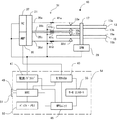
図1は、本発明の実施の形態にかかる磁気ディスク装置の平面図で、図2はブロック図で、図3は電源/ドライバとMPUユニットの構成を示す図で、図4は、リード/ライト・チャネルのブロック図で、図5はヘッド・ジンバル・アセンブリ(以下、HGAという。)の斜視図である。図1および図2において、磁気ディスク装置10は、ベース11に2枚の磁気ディスク13、15と、ヘッド・スタック・アセンブリ31、フレキシブル・ケーブル25、およびフレキシブル・ケーブル25を外部の回路基板54に接続する端子27が設けられている。磁気ディスク13、15は、ベース11に設けられたスピンドル・モータ29のロータ部にクランプで固定されており、スピンドル軸17を中心にして一体となって毎分15000回といった回転速度で回転駆動するように構成されている。
[Outline of magnetic disk unit]
FIG. 1 is a plan view of a magnetic disk device according to an embodiment of the present invention, FIG. 2 is a block diagram, FIG. 3 is a diagram showing the configuration of a power supply / driver and an MPU unit, and FIG. FIG. 5 is a perspective view of a head gimbal assembly (hereinafter referred to as HGA). 1 and 2, the
磁気ディスク13、15は、それぞれ記録面13a、13b、15a、15bを備えている。ヘッド・スタック・アセンブリ31は、ヘッド・ジンバル・アセンブリ35a、35b、35c、35dとアクチュエータ・アセンブリ21とで構成されている。図8は、磁気ディスク13の記録面13aのフォーマット構造を説明する図である。磁気ディスク装置10は、データ面サーボ方式を採用しており、各記録面13a、13b、15a、15bには、記録面13aを例にして図8(A)に示したように放射状に等間隔で並んだ複数のサーボ・セクタ133にサーボ・データが書き込まれており、サーボ・データによりサーボ・トラックが定義される。以後、サーボ・トラックを単にトラックということにする。
The
サーボ・データは、サーボ・データを再生する前に増幅器の増幅率を調整するためのサーボAGC、サーボ・データの開始を示すサーボ・マーク、グレイ・コードで書き込まれたトラック・アドレス、円周方向におけるサーボ・セクタの位置を示すセクタ・アドレス、およびトラックの中心から再生ヘッドがシフトしている量を示すPESを生成するためのバースト・パターンなどで構成されている。バースト・パターンは書き込み位置が半径方向にずれている4種類のパターンで構成されている。各サーボ・セクタ133の間には、データ領域135が定義されている。
Servo data includes servo AGC for adjusting the amplification factor of the amplifier before reproducing the servo data, servo mark indicating the start of servo data, track address written in gray code, circumferential direction And a burst pattern for generating a PES indicating the amount by which the reproducing head is shifted from the center of the track. The burst pattern is composed of four types of patterns whose write positions are shifted in the radial direction. A
図8(B)は半径方向に隣接する3つのトラックr1、r2、r3を示している。図8(B)に例示したように、サーボ・トラックr2上には、サーボ・セクタ139cと139dの間のデータ領域135に、3個のデータ・セクタ143a、143b、143cが定義されており、他のサーボ・セクタ間および他のトラックにおけるデータ領域135についても同様である。各データ・セクタは、ユーザ・データの書き込み時に直近のサーボ・セクタの位置を基準にしてそれぞれの円周方法の位置が特定できるようにフォーマットされている。磁気ディスク13aの一部にはユーザがアクセスできない専用領域が定義されており、本実施の形態を実現するために突起物の位置を登録する登録プログラムおよびシーク動作中およびフォローイング動作中にフライング・ハイトを制御するFH制御プログラムが格納されている。
FIG. 8B shows three tracks r1, r2, and r3 adjacent in the radial direction. As illustrated in FIG. 8B, on the servo track r2, three
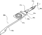
図2において、HGA35a、35b、35c、35dには、磁気ディスクの記録面13a、13b、13c、13dに対応してヘッド/スライダ33a、33b、33c、33dが設けられている。HGA35a、35b、35c、35dはほぼ同様の構成になっており、HGA35aを例にして図5を参照しながらその構造を説明する。HGA35aは、図5に示すように配線一体型サスペンションとして、ヘッド/スライダ(図示せず。)、ベース・プレート93a、ロード・ビーム95a、ヒンジ94a、マウント・プレート91aおよびフレキシャ97aによって主要部が構成されている。ベース・プレート93aには開口部が形成され、この開口部を利用してベース・プレート93aに固定されたマウント・プレート91aをスウェージング加工することにより、HGA35aをアクチュエータ・アセンブリ21のアクチュエータ・アームに固定する。
In FIG. 2, HGAs 35a, 35b, 35c and 35d are provided with head /
ヒンジ94aは弾性を備えており、ベース・プレート91aとロード・ビーム95aを連結してヘッド/スライダが適切に磁気ディスク上を浮上できるようにロード・ビーム95aに対して押付荷重を与えている。HGA35aの先端部には、ランプ23とともにロード/アンロード方式を実現するためのリフト・タブ96aが形成されている。フレキシャ97aは、HGA35aの先端部からコネクタ部までクランク状に延在するリード線92aを先端側で保持し、ロード・ビーム95aとベース・プレート93aにレーザでスポット溶接されている。リード線92aはヘッド/スライダに形成された磁気ヘッドとフレキシブル・ケーブル25を接続する4本の導体を含んでいる。導体の数は、ヘッド/スライダの構成により変わり、ヘッド/スライダの中にヘッドの熱膨張量を制御するためのヒータが埋め込まれている場合は6本または8本になる。
The
フレキシャ97aのフレキシャ・タングにはヘッド/スライダ33aが固定され、トラックのフォローイング動作中にピボット運動またはジンバル運動をして、磁気ヘッドのフライング・ハイトを所定の範囲に維持する。ヘッド/スライダ33a、33b、33c、33dはそれぞれ誘導型記録ヘッドとGMR(巨大磁気抵抗効果)再生ヘッドを含んでおり、その構造については図7を参照してあとで説明する。薄いステンレス鋼板で形成されたロード・ビーム95aの表面には圧電アクチュエータ41aが設けられている。同様に、HGA35b、35c、35dにも圧電アクチュエータ41b、41c、41dが設けられている。
A head /
圧電アクチュエータは、たとえばチタン酸ジルコン亜鉛(PZT)などの圧電素子で構成される。圧電素子は、操作量としての直流電圧を印加するとピエゾ効果により伸縮の変位を起こす。本実施の形態では、圧電アクチュエータ41a、41b、41c、41dに印加する直流電圧の大きさを制御することによりロード・ビームが歪んで、各ヘッド/スライダの位置が図5のZ方向に変化してフライング・ハイトを制御できるようにHGA35a、35b、35c、35dを構成している。この構成により各ヘッド/スライダ33a、33b、33c、33dの磁気ヘッドのフライング・ハイトを個別に制御することができるようになっている。
The piezoelectric actuator is composed of a piezoelectric element such as zircon zinc titanate (PZT). When a direct current voltage as an operation amount is applied to the piezoelectric element, the piezoelectric element causes a displacement of expansion and contraction due to a piezoelectric effect. In this embodiment, the load beam is distorted by controlling the magnitude of the DC voltage applied to the
図1および図2に戻って、アクチュエータ・アセンブリ21は、HGA35a、35b、35c、35dを支持するアクチュエータ・アーム、ピボット軸18を構成するピボット・アセンブリの固定部分およびボイス・コイル37を保持したコイル・サポートによりロータリ式アクチュエータとして構成され、HGA35a、35b、35c、35dをピボット軸18を中心にして回動させる。ボイス・コイル37およびヨーク19は、ボイス・コイル・マグネット(図示せず。)とともに、ボイス・コイル・モータ(以下、VCMという。)を構成する。キャリッジ・アセンブリ21には、ヘッド・アンプ39が取り付けられている。ヘッド・アンプ39は、リード・アンプ、ライト・ドライバ、ドライバ・レジスタ、ヘッド切替回路などで構成されている。
1 and 2, the
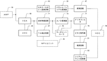
ベース11の外側には、リード/ライト・チャネル43、サーボ・コントローラ55、MPUユニット45、電源/ドライバ47、ハード・ディスク・コントローラ(HDC)49、およびバッファ・メモリ53を実装する回路基板54が取り付けられている。リード/ライト・チャネル43は、ユーザ・データやサーボ・データの記録信号および再生信号を処理する回路であり、詳細は図4を参照してあとで説明する。
Outside the
サーボ・コントローラ55は、アドレス検出回路、サンプル・ホールド回路、サンプリング信号生成回路、および演算回路を備えている。アドレス検出回路は、リード/ライト・チャネル43のA/D変換器73(図4)から出力されたリード・パルス信号からサーボ・データのサーボ・マークを読み取ってサーボ割り込み信号を生成し、さらにサーボ・セクタのセクタ・アドレス信号およびトラック・アドレス信号を生成してMPUユニット45に送る。サンプル・ホールド回路は、リード/ライト・チャネル43の波形等価回路71(図4)から送られたバースト・パターンの再生信号(以後、バースト信号という。)を再生ヘッドが新しいサーボ・データを再生するまで保持する。
The
サンプリング信号生成回路は、波形等価回路71(図4)から送られた4つのバースト信号の再生タイミングを決めるサンプル・タイミング信号を生成する。サーボ・コントローラ55は、サンプル・ホールド回路、サンプリング信号生成回路、および演算回路でPESを生成し、MPUユニット45に送る。HDC49は、ホスト・コンピュータとのインターフェースの役割をし、バッファ・メモリ53を制御するバッファ・コントローラやホスト・コンピュータから送られたデータ・ビットに対する訂正ビットを生成したり磁気ディスクから再生したユーザ・データを訂正したりするECC回路などを含んでいる。
The sampling signal generation circuit generates a sample timing signal that determines the reproduction timing of the four burst signals sent from the waveform equivalent circuit 71 (FIG. 4). The
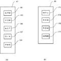
バッファ・メモリ53は、ホスト・コンピュータと磁気ディスク装置10との間で高速のデータ転送を実現するために使用する。電源/ドライバ47は、図3(A)に示すように、スピンドル・モータ29に操作電流を供給するSPMドライバ161、ボイス・コイル37に操作電流を供給するVCMドライバ163、圧電アクチュエータ41a、41b、41c、41dに操作電圧を供給するACTドライバ165、MPUユニットから送られたディジタルの操作信号をアナログ信号に変換して各ドライバに供給するDAコンバータ167、および磁気ディスク装置全体に電源を供給する電源回路169などで構成されている。回路基板54には、ホスト・コンピュータとデータ通信をするためのインターフェース・コネクタ51が取り付けられている。SPMドライバ161、VCMドライバ163、ACTドライバ165はいずれもMPUユニット45から送られた操作信号で制御される。
The
ACTドライバ165は、本実施例において圧電アクチュエータ41a、41b、41c、41dとともにフライング・ハイトの制御機構を構成する。ACTドライバ165は、MPUユニット45から受け取った操作信号に応じて圧電アクチュエータ41a、41b、41c、41dに印加する操作電圧を個別に制御して各磁気ヘッドのフライング・ハイトを制御する。本実施例では、ACTドライバ165が圧電アクチュエータ41a、41b、41c、41dに操作電圧を供給していないときは、各磁気ヘッドのフライング・ハイトが最低になっており、このときのフライング・ハイトを基準フライング・ハイトという。
In the present embodiment, the
基準フライング・ハイトは、理想的なフライング・ハイトとして設定された目標値としての意義を有している。ただし、ヘッド/スライダが実際に磁気ディスク上を浮上しているときの基準フライング・ハイトは、空気流からヘッド/スライダの空気軸受面が受ける圧力とロード・ビームによる押付荷重のバランス状態の変化に応じて若干変動した値を示す。また、基準フライング・ハイトは磁気ディスクの半径方向の位置により空気流の速度や空気軸受面の軸とトラックの接線でつくる角度が変化するため異なった値になる。このように基準フライング・ハイトはある一定の値ではなく、ユーザ・データを記録したり再生したりする時のために設定された所定の範囲の値となる。基準フライング・ハイトは、ACTドライバ165が圧電アクチュエータ41a、41b、41c、41dにある値の操作電圧を供給したときに得ることができるようにしてもよい。
The reference flying height has a significance as a target value set as an ideal flying height. However, the reference flying height when the head / slider actually floats on the magnetic disk is the change in the balance between the pressure applied to the air bearing surface of the head / slider from the air flow and the pressing load by the load beam. The values slightly changed accordingly. The reference flying height varies depending on the position of the magnetic disk in the radial direction because the speed of the air flow and the angle formed by the axis of the air bearing surface and the track are changed. Thus, the reference flying height is not a fixed value but a value in a predetermined range set for recording or reproducing user data. The reference flying height may be obtained when the
MPUユニット45は、図3(B)に示すように、磁気ディスク装置10の全体動作を制御するMPU171、各種プログラムやファームウエアを格納するROM175、各種パラメータや参照テーブルを格納するEEPROM177、プログラムの実行や作業領域として使用するRAM173などで構成されている。MPU171は、シーク動作をするときにホスト・コンピュータから目標トラックのアドレスを指示されると、サーボ・データから読み取ったトラック・アドレスでシーク動作中の磁気ヘッドの位置を認識してVCMドライバ163に操作信号を送る。
As shown in FIG. 3B, the
MPU171は、シーク動作中に再生ヘッドが通過するサーボ・セクタからトラック・アドレスを読み取ってヘッド/スライダの実際の移動速度を計算し、あらかじめ速度テーブルで定められた値との偏差を小さくするようにVCMドライバ163に対する操作信号を生成してヘッド/スライダの速度制御をする。MPU171は、再生ヘッドが目標トラックに近づくと速度制御から位置制御に切り換え、サーボ・コントローラ55から送られたPESに基づいて再生ヘッドを目標位置に位置づけるために、VCMドライバ163に送る操作信号の値を計算する。MPU171が、再生ヘッドを目標位置に位置づけるためにPESを利用してVCMドライバ163を制御することをフォローイング動作という。MPU171は、磁気ディスク13の専用領域からRAM173に読み出された登録プログラムおよびFH制御プログラムを実行する。
The
EEPROM177には、突起物の存在や磁性層の損傷などに起因した欠陥データ・セクタのアドレスや、欠陥データ・セクタが依存するサーボ・セクタのアドレスを登録しておく欠陥マップ(以後、DMという。)が設けられている。データ・セクタとサーボ・セクタの依存関係は、図8(B)を参照してあとで説明する。EEPROM177には、突起物に接触しない磁気ヘッドのフライング・ハイトを設定するための操作情報を登録した制御テーブルが設けられている。MPU171は、操作情報に基づいてACTドライバ165に供給する操作信号を生成し、ACTドライバ165は操作信号に対応した操作電圧を圧電アクチュエータに印加する。本実施の形態においては、後述するようにMPU171はFH制御プログラムを実行して、DMに登録された突起物の位置情報と制御テーブルに登録された操作情報に基づいて磁気ヘッドのフライング・ハイトを制御し突起物と磁気ヘッドの接触を回避する。
In the
[リード/ライト・チャネルの構成]
図4を参照してリード/ライト・チャネル43の概略構成を説明する。リード/ライト・チャネル43は、ライト系回路とリード系回路で構成され、MPUユニット45から受け取ったリード・ゲート信号およびライト・ゲート信号で動作モードを切り換える。ライト系回路は主として、変調回路67、パラレル/シリアル変換器65、およびNRZ−NRZI変換回路63で構成される。変調回路67は、HDC49から送られたユーザ・データを記録媒体に記録するのに適したRLL(Run Length Limited)コードに変換する。パラレル/シリアル変換器65は、変調回路から送られたRLLコードを直並列変換する。
[Configuration of read / write channel]
A schematic configuration of the read /
NRZ−NRZI変換回路63は、ユーザ・データの形式であるNRZ方式の信号を磁気ディスクに対する記録に適したNRZI(Non-Return to Zero Inverse)方式の信号に変換してヘッド・アンプ39のライト・ドライバに送る。リード系回路は主として、可変利得増幅器(VGA)69、自動利得制御部(AGC)85、波形等価回路71、A/D変換器73、FIRフィルタ77、ビタビ復号器79、復調回路81、シリアル/パラレル変換器83で構成される。可変利得増幅器69と自動利得制御部85は、ヘッド・アンプ39から受け取ったユーザ・データやサーボ・データの再生信号の振幅を一定にする。
The NRZ-NRZI conversion circuit 63 converts the NRZ format signal, which is the format of user data, into an NRZI (Non-Return to Zero Inverse) format signal suitable for recording on the magnetic disk, and writes the write data of the
波形等価回路71は、高域ゲインをプログラマブルに変更できるロー・パス・フィルタを備え、ノイズを除去して波形を等価する。等価とは、再生信号の波形を想定したPR(Partial Response)のクラスに合わせる信号処理をいう。A/D変換回路73は、微分回路、フィルタ、比較回路などを備え、アナログの再生信号からリード・パルス信号を生成する。FIR(Finite Impulse Response)フィルタ77は直列接続された複数の遅延演算子を備えたディジタル・フィルタで、タップの値を設定して復号しやすい信号を生成する。ビタビ復号器79は、FIRフィルタ77で処理された信号をPRML(Partial Response Maximum Likelihood)回路を使って処理しRLLコードとして出力する。復調回路81は、RLLコードをユーザ・データ形式のNRZ符号列のデータに変換する。シリアル/パラレル変換器83は、NRZ符号列を並列データに変換してHDC49に送る。
The waveform
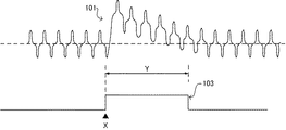
リード/ライト・チャネル43は、自動利得増幅回路69の出力に接続されたTA検出回路87を備えている。TA検出回路87は、GMR再生ヘッドが突起物に接触したことにより発生した再生信号のゆらぎをTAとして検出して、リード/ライト・チャネルの動作を一次停止させる回路である。図6にTAが発生したときの再生信号の様子を示す。位置Xで突起物にGMR再生ヘッドが接触すると、自動利得増幅器69から送られた再生信号101のDCレベル103が期間Yの間だけ上昇する。本実施の形態では、TA検出回路87は、DCレベル103からTAの発生を検出してTA検出信号をMPUユニット45に通知する。
The read /
[磁気ヘッドの構成]
図7は、矢印A方向に回転する磁気ディスク13の記録面13a上をヘッド/スライダ33aが浮上している様子を示す側面図である。ヘッド/スライダ33aは、回転により磁気ディスク表面に発生した気流から揚力を受ける空気軸受面113a、フレキシャ・タングに対する固定面111a、リーディング・エッジ(空気流入端)側面117a、トレイリング・エッジ(空気流出端)側面115aを備える。内部には、トレイリング・エッジ側面115a寄りに薄膜記録ヘッド119aとGMR再生ヘッド121aが形成されている。GMR再生ヘッド121aに代えて、MR(磁気抵抗効果)再生ヘッドを採用することもできる。
[Configuration of magnetic head]
FIG. 7 is a side view showing the head /
記録ヘッド119aがデータ書き込みのための磁界を発生するライト・ギャップおよび再生ヘッドが磁気ディスクに記録された磁界の変化を検出するリード・ギャップ121aは、空気軸受面113a上で露出している。記録ヘッド119aの位置と再生ヘッド121aの位置は、ヘッド/スライダ33aの長手方向に所定の間隔だけ離れている。
A write gap in which the
記録ヘッド119aは、磁極とコイルで構成されており、磁極は空気軸受面113aにおいてライト・ギャップを形成して書き込み用の磁界を発生させている。コイルは、トレイリング・エッジ側面115aに形成されたスライダ・パッド(図示せず。)に接続されている。スライダ・パッドからコイルに記録電流を流してライト・ギャップに信号磁界を発生させ、磁気ディスクの磁性層を磁化する。
The
GMR再生ヘッド121aは、絶縁層、シールド層、巨大磁気抵抗効果膜(GMR膜)、および磁区制御膜などで構成されている。磁区制御膜はGMR膜の両側に形成されGMR膜に一定方向のバイアス磁界を印加するためのものである。GMR素子の両端は、トレイリング・エッジ側面115aに形成されたスライダ・パッドに接続され、スライダ・パッドからバイアス電流またはセンス電流が供給される。GMR膜の抵抗値は、磁性層から発生した信号磁界の影響を受けて変化するので、その抵抗値の変化をバイアス電流に対する電圧の変化として検出することにより、磁気ディスクに記録されている情報を読み出すことができる。
The GMR read
図7において、ヘッド/スライダ33aは、記録面13aの表面からわずかの間隔で浮上している。記録面13a上に浮上しているヘッド/スライダ33aは、リーディング・エッジ側面117a側におけるフライング・ハイトが、トレイリング・エッジ側面115a側におけるフライング・ハイトよりもわずかに高い。これは、ヘッド/スライダ33aが安定して浮上できる姿勢を維持して、空気軸受面113aと記録面13aの表面との間を空気流が円滑に流れ、空気軸受面113aが適切な浮力を受けることができるようにするためである。
In FIG. 7, the head /
したがって、フライング・ハイトは、空気軸受面113aにおける測定位置に応じてわずかに異なる値となる。本明細書では、記録ヘッドのフライング・ハイト、再生ヘッドのフライング・ハイト、ヘッド/スライダのフライング・ハイトまたは磁気ヘッドのフライング・ハイトといったように空気軸受面での位置を特定してフライング・ハイトを定義することにする。ただし、ヘッド/スライダのフライング・ハイトは、特定の位置を問題にしない場合に使用する。磁気ヘッドのフライング・ハイトは、記録ヘッドのフライング・ハイトおよび再生ヘッドのフライング・ハイトまたはそのいずれか一方という意味で使用する。
Therefore, the flying height has a slightly different value depending on the measurement position on the
[TAの原因となる突起物の位置を示すアドレスの登録]
図8(B)において、トラックr1、r2、r3は、バースト信号から生成されるPESにより中心位置が画定され、フォローイング動作中は再生ヘッドがそれらのトラックの中心またはトラック中心間の所定の位置に位置づけられる。図7で説明したように記録ヘッド119aと再生ヘッド121aとの間には間隔があるため、ロータリー式アクチュエータで移動するヘッド/スライダ33aにはヨー角が発生し、同一トラック上にあるサーボ・セクタ133とデータ・セクタは一般に対応しない。たとえば、再生ヘッド121aがトラックr3に位置づけられたときに、記録ヘッド119aがトラックr1上に位置づけられることがある。このときトラックr3に書き込まれたユーザ・データを再生するためには、MPU171はファームウエアに組み込まれた位置計算プログラムを実行して再生ヘッド121aをトラックr1の位置に位置づける。
[Registering the address indicating the position of the protrusion causing the TA]
In FIG. 8B, the tracks r1, r2, and r3 are centered by the PES generated from the burst signal, and during the following operation, the reproducing head is located at the center of the tracks or a predetermined position between the tracks. Is positioned. As described with reference to FIG. 7, since there is a gap between the
矢印A方向に回転している磁気ディスク13aのトラックr2に対してフォローイング動作をするとき、再生ヘッド121aは、サーボ・セクタ139aからサーボ・セクタ139iに向かって順番にバースト・パターンを再生し、波形等価回路71はバースト信号をサーボ・コントローラに出力する。サーボ・コントローラ55は、各サーボ・セクタからバースト信号を受け取るタイミングでPESを生成してMPUユニット45に送り、MPU171は再生ヘッド121aを目標位置に位置づけるために必要なVCMドライバ163に対する操作信号の値を計算する。
When performing the following operation on the track r2 of the
再生ヘッド121aがサーボ・セクタ139cのバースト・パターンを再生してからサーボ・セクタ139dのバースト・パターンを再生するまでの間は、サーボ・コントローラ55はサーボ・セクタ139cから再生した信号をホールドしており、データ・セクタ143a、143b、143cの位置では、再生ヘッド121aの現実の位置情報に基づいた制御は行われない。したがって、サーボ・セクタ139cに続くデータ・セクタ143a、143b、143cに対する再生ヘッド121aの位置は、サーボ・セクタ139cのバースト・パターンから生成したPESに依存する。このことを、データ・セクタ143a、143b、143cはサーボ・セクタ139cに依存するということにする。
The
いま、データ・セクタ141のように磁気ディスクの各記録面13a、13b、15a、15bに突起物が生じている場合に各記録面を検査して、突起物の存在する位置を示すアドレスをEEPROM177のDMに登録し、磁気ヘッドと突起物の接触を回避するのに必要なACTドライバ165に供給する操作信号を生成するための操作情報を登録する手順を図9のフローチャートで説明する。突起物はサーボ・セクタに存在する場合もあるが、サーボ・セクタに存在する突起物はあらかじめ検査して当該サーボ・セクタを含むトラック全体を使用禁止にしたり、当該サーボ・セクタに近接するサーボ・セクタを使用禁止にしたりして前処理をしておき、サーボ・セクタはすべてサーボ・データの読み取りが可能なようになっているものとする。また、RAM173には、磁気ディスクの専用領域から登録プログラムが読み出されてMPU171が実行できるようになっているものとする。
Now, when projections are generated on the
図9に示した手順は、磁気ディスク装置10のMPU171が登録プログラムを実行して行う。ブロック201において、すべてのデータ・セクタに検査データを書き込む。このときMPUユニット45から電源/ドライバ47のACTドライバ165には操作信号が供給されていない。したがって、各ヘッド・スライダ33a、33b、33c、33dの磁気ヘッドは、基準フライング・ハイトで浮上している。
The procedure shown in FIG. 9 is performed by the
ブロック203では、MPU171は、再生ヘッド121aを記録面13aの最も内側のシリンダに位置づけてフォローイング動作をさせ、記録面13aの最内周トラックに記録した検査データを再生する。記録面13aの最内周トラックが1回転する間に突起物を検出しないときは、MPU171はヘッド・アンプ39のヘッド切替回路に信号を送ってヘッド/スライダ33bの再生ヘッドを有効にして1回転する間に記録面13bの最内周トラックに記録した検査データを再生する。以下の検査では、検査データを再生する各記録面の各検査位置のトラックで磁気ディスクを最低1回転させてから再生ヘッドを他の検査位置のトラックに移動させる。各検査位置のトラックで磁気ディスクが1回転する間に突起物を検出した場合はその位置情報と操作情報を登録してから再生ヘッドを他の検査位置に移動させる。
In
ブロック205では検査データの再生中に、リード/ライト・チャネル43のTA検出回路87がTAの発生状況を監視する。TA検出回路87が、いずれかの記録面の検査位置で再生した可変利得増幅器69の再生信号から、図6に示したTA検出信号を検出したときはMPUユニット45に通知する。MPU171は、TA検出信号を受け取ると、突起物の存在する位置のアドレスを登録するまで当該記録面の検査位置のトラックに再生ヘッドを位置づけておく。
In
たとえば、記録面13aの検査データから図8(B)のトラックr2にあるデータ・セクタ141の位置に発生していた突起物と再生ヘッドが接触してTA検出回路87がTA検出信号を出力したときは、ヘッド/スライダ33aの再生ヘッドを有効にしたままで、MPU171は記録面13aのトラックr2の検査データの再生を続ける。このとき再生ヘッドは基準フライング・ハイトの状態にあるので、1回転ごとに再生ヘッドが突起物に接触してその都度TA検出信号がMPUユニット45に出力される。
For example, the TA detection circuit 87 outputs the TA detection signal when the reproducing head contacts the projection generated at the position of the
ブロック209では、MPU171は、登録プログラムにおいて整数p=1を設定する。整数pの値は、ACTドライバ165に加える操作信号を段階的に設定するために使用される。基準フライング・ハイトで浮上するときは整数pは0に設定されている。ブロック211でMPU171は、ACTドライバ165が圧電アクチュエータに印加する単位操作電圧をXとしたとき、操作情報である整数pに基づいて操作電圧pX=Xに相当する操作信号を生成し、ACTドライバ165に供給する。
In
ACTドライバ165は、TA検出信号を出力した再生ヘッド121aに対応する圧電アクチュエータ41aに操作量としての操作電圧Xを印加し、ヘッド/スライダ33aのフライング・ハイトをそれに相当する量だけ上昇させる。トラック1周に渡ってフライング・ハイトを上昇させたままにしておくと、バースト・パターンの再生能力が低下してフォローイング動作に支障をきたすので、突起物の存在するデータ・セクタ141の近辺でだけフライング・ハイトを上昇させ、それ以外の場所では基準フライング・ハイトに戻すようにする。登録時のフォローイング動作において、フライング・ハイトを制御するためにACTドライバ165に操作信号を供給するタイミングと停止するタイミングは、図13を参照してあとで説明する実際のフォローイング動作中におけるタイミングに合わせておくことで、獲得した操作情報を使用して確実に磁気ヘッドと突起物との接触を最低のフライング・ハイトで回避できるようになる。
The
ブロック213では、磁気ディスクの回転によりつぎにデータ・セクタ141が再生ヘッドの位置にきたときにTAが発生するかどうかを判断する。再度TAが発生する場合はMPU171はブロック215でp=p+1=2に設定し操作電圧2Xに相当する操作信号を生成してACTドライバ165に送る。ブロック211でACTドライバ165は、圧電アクチュエータ41aに操作電圧2Xを印加し、ヘッド/スライダ33aのフライング・ハイトをそれに相当する量だけ上昇させる。
In
ブロック211〜ブロック215を繰り返すと、整数pが1ずつ増えるに従いデータ・セクタ141が再生ヘッドを通過する時点での再生ヘッドのフライング・ハイトは単位操作電圧Xに相当する値ずつ上昇し、再生ヘッドは磁気ディスクの1回転ごとに異なるフライング・ハイトでデータ・セクタ141の上を飛行する。やがて、ヘッド/スライダ33aのフライング・ハイトがデータ・セクタ141が通過するときに突起物に接触しなくなる程度まで上昇すると、ブロック213ではフライング・ハイトが検出されなくなりブロック217に移行する。
When the
ブロック217では、TAが発生したデータ・セクタ141が依存しているサーボ・セクタ139hのシリンダ・アドレス、セクタ・アドレス、ヘッド番号を突起物の位置情報としてEEPROM177のDMに登録し、整数pを突起物と磁気ヘッドの接触を回避するためにACTドライバ165に供給する操作信号を生成するための操作情報としてEEPROM177の制御テーブルに登録する。記録ヘッドまたは再生ヘッドのフライング・ハイトは、素子の熱膨張により温度が上昇するほど低くなるので、登録時の温度と実際の使用時に想定する温度との差に基づいて計算した整数pの補正値を同時に登録してもよい。また、再生ヘッドのフライング・ハイトと記録ヘッドのフライング・ハイトの差が大きい場合は、ヘッド/スライダの形状寸法と浮上時のヘッド/スライダの姿勢に基づいて整数pを補正し補正値を登録する。登録される整数pの補正値も操作情報の一部となる。操作情報は、MPU171が、圧電アクチュエータ41aに印加する操作電圧を決定するためにACTドライバ165に供給する操作信号を生成するために使用される。
In
サーボ・セクタ139hのシリンダ・アドレスおよびセクタ・アドレスは、フライング・ハイトを上昇させた後では読み取りにくくなるので、最初にTAを検出した時点で読み取っておくとよい。データ・セクタ141が依存しているサーボ・セクタ139hのアドレス情報は、データ・セクタ141が再生ヘッドの位置に到達する前に読み取られるので、TAが発生してもMPU171はサーボ・セクタ139hのアドレスを認識することができる。MPU171は、シリンダ・アドレスとヘッド番号で4つの記録面の中から突起物が存在する記録面のトラックを特定することができる。
Since the cylinder address and sector address of the
ブロック217で突起物の位置情報とフライング・ハイトの操作情報の登録が完了すると、ブロック219に移行し、検査をしたトラックが最終トラックか否かを判断する。本実施例における最終トラックは、最も外側のシリンダを構成する記録面15bのトラックである。この時点では記録面13aの最内周トラックについて突起物の検査している状態なので、ブロック221に移行し、MPU171は、記録面13bに対応する再生ヘッドを有効にする。その後、ブロック205に戻って記録面13bの最内周トラックに記録された検査データを再生してブロック207でTAの発生を確認する。TAを検出すればブロック209に移行して、前述のようにTAを検出したデータ・セクタが依存するサーボ・セクタのシリンダ・アドレス、セクタ・アドレス、ヘッド番号、整数pおよびその補正値を登録する。
When the registration of the projection position information and the flying height operation information is completed in
TAを検出しない場合は、ブロック207からブロック219に移行して最終トラックまで検査したかどうかを確認する。最終トラックまで検査が終了していないときは、ブロック221において、記録面13a、13b、15a、15bのトラックで構成される現在のシリンダに対する検査が終了すると、シリンダを変更する。シリンダの変更は、1トラック・ピッチの1/4または1/2といった値ずつ、PESを利用して最外周トラック側に再生ヘッドの位置をシフトすることにより行う。1トラック・ピッチ以下ずつシフトしてゆくのは、トラックの中心間に存在する小さい突起物まで高い精度で検出できるようにするためである。
If the TA is not detected, the process goes from
ブロック219で最終トラックまで検査および登録が完了したことを確認したらブロック223で突起物の位置登録作業を完了する。ブロック223では、EEPROM177のDMに突起物が検出されたデータ・セクタが依存するサーボ・セクタのシリンダ・アドレス、セクタ・アドレス、ヘッド番号が位置情報として登録され、EEPROM177の制御テーブルに整数pおよびその補正値が記録されている。以後、突起物が検出されたデータ・セクタが依存するサーボ・セクタを突起物セクタということにする。また、突起物セクタが属するトラックを突起物トラックということにする。
When it is confirmed in
ブロック225では、同一トラックにおいて突起物セクタの前後に連続して7個ずつ選択した、サーボ・セクタを欠陥登録をする。図8(B)でいえば、サーボ・セクタ139hが突起物セクタである場合に、サーボ・セクタ139a〜139gの7個のサーボ・セクタとさらに、サーボ・セクタ139i以降の連続7個のサーボ・セクタがDMに欠陥登録される。ここで欠陥登録されるサーボ・セクタは、突起物との接触を回避するために磁気ヘッドのフライング・ハイトが基準フライング・ハイトより上昇しているためにユーザ・データの記録には使用できないデータ・セクタが依存するサーボ・セクタである。MPU171は、欠陥登録されたサーボ・セクタに依存するデータ・セクタを使用禁止として扱い、ユーザ・データの記録には使用しない。
In
図9の手順では、最内周シリンダ側から最外周シリンダ側に向かって検査を進行させたが、最外周シリンダ側から最内周シリンダ側に向かって検査を進行させてもよい。また、ブロック211からブロック215では、フライング・ハイトが基準フライング・ハイトから漸次上昇するように整数pをステップ・アップしたが、最初の接触でTAを検出したら大きい整数pを設定して一旦フライング・ハイトを十分に高い位置まで上昇させ、その後再びTAを検出するまで整数pをステップ・ダウンしてフライング・ハイトを漸次下降させてもよい。この場合は、フライング・ハイトを漸減していったときに再びTAを検出したときのpより1つ大きいpを登録することになる。
In the procedure of FIG. 9, the inspection proceeds from the innermost cylinder side toward the outermost cylinder side. However, the inspection may proceed from the outermost cylinder side toward the innermost cylinder side. In
図9の手順では、GMR再生ヘッドに対するTAを検出して突起物とヘッド/スライダの接触を検出し、接触を回避する最低のフライング・ハイトを得るために必要な圧電アクチュエータに印加すべき電圧と突起物の位置を求めて登録した。しかし、本発明において突起物を検出する方法はTAの検出に限定されるものではなく、突起物とヘッド/スライダの接触により生じた振動や音響などを検出して行ってもよい。 In the procedure of FIG. 9, the TA to the GMR reproducing head is detected to detect the contact between the protrusion and the head / slider, and the voltage to be applied to the piezoelectric actuator necessary to obtain the minimum flying height to avoid the contact The position of the protrusion was obtained and registered. However, the method for detecting a protrusion in the present invention is not limited to the TA detection, and may be performed by detecting vibration, sound, etc. caused by the contact between the protrusion and the head / slider.
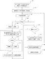
[シーク動作の方法]
つぎに、EEPROM177のDMに登録した突起物セクタの位置情報と、制御テーブルに登録した整数pおよびその補正値からなる操作情報を使用して、突起物と磁気ヘッドの接触を回避しながらシーク動作をする方法を図10のフローチャートを参照して説明する。図11は、図10の手順を実施するときのヘッド/スライダの位置と突起物の位置を示す図である。
[Method of seek operation]
Next, seek operation is performed while avoiding contact between the protrusion and the magnetic head by using the position information of the protrusion sector registered in the DM of the
ブロック301における前提状態として、図11には、記録面13aに存在する#01から#25までのトラックと、シーク動作を開始する前と開始した後のヘッド/スライダ33aの位置が示されている。突起物と磁気ヘッドの接触の回避は、シーク動作中にMPU171がFH制御プログラムを実行して制御テーブルに登録された操作情報に基づく操作信号をACTドライバ165に供給し、ACTドライバが操作量として操作電圧を圧電アクチュエータに印加して制御量としての磁気ヘッドのフライング・ハイトを変化させることにより行うようになっている。また、磁気ディスク13、15の各記録面に対して図9の手順で突起物の検査が終了しており、記録面13aの#11のトラックに突起物181が検出され、その位置情報と操作情報がEEPROM177に登録されている。
As a precondition in the
ヘッド/スライダ33aは、図7に示したように再生ヘッド121aと記録ヘッド119aを備えている。記録ヘッド119aと再生ヘッド121aは、ロータリー式アクチュエータに特有に存在するスキュー角により発生したトラックの接線に対するヨー角の存在により、同一トラック上にはない。この例ではシーク動作を開始する前には、再生ヘッド121aが#01のトラックに位置づけられているが、記録ヘッド119aは#04のトラックに位置づけられている。
As shown in FIG. 7, the head /
現在トラック#01に再生ヘッド121aが位置づけられてヘッド/スライダ33aは基準フライング・ハイトで浮上している。磁気ディスク装置10は、トラック#01上に記録されたデータ・セクタからユーザ・データを再生する再生動作か、トラック#01上の各サーボ・セクタからサーボ・データを再生しているシーク動作か、あるいは、トラック#04にユーザ・データを記録している記録動作のいずれかの状態にある。
The reproducing
ブロック303では、ホスト・コンピュータから、トラック#18のユーザ・データを再生するためのリード・コマンドを受け取る。リード・コマンドに代えて、トラック#21にユーザ・データを書き込むライト・コマンドであったとしても、ヘッド/スライダ33aが移動しなければならない距離は同じになり、本実施の形態におけるフライング・ハイトの制御は同一になる。ブロック305では、MPU171がEEPROM177のDMに登録された突起物のアドレス情報の中に、各記録ヘッドまたは各再生ヘッドがシーク動作中に通過するトラックがあるかどうかを判断する。具体的には、MPU121は、シーク動作中に磁気ヘッドが通過する#02から#20のトラックの中にDMに登録された突起物トラックがあるかどうかを調べる。
In
ブロック305では、シーク動作中に各磁気ヘッドが通過するトラックの中に突起物トラックが存在しなければブロック309に移行して通常のシーク動作をする。すなわち、基準フライング・ハイトを維持しながらシーク動作を行い、ブロック315で再生ヘッドは#18のトラックに位置づけられてフォローイング動作に移行する。ブロック305でシーク動作中に磁気ヘッドが通過するトラックが記録面13aの突起物トラック#11を含んでいることをMPU171がDMに登録された位置情報から認識したときは、ブロック307に移行する。
In
MPU171は、VCMドライバ163に操作信号を送らないで、基準フライング・ハイトのままで#01シリンダから#18シリンダに向かってキャリッジ・アセンブリ21のシーク動作を開始させる。MPU171は、磁気ヘッドが突起物トラック#11を通過する直前にフライング・ハイトを上昇させ、突起物トラック#11を通過した直後に基準フライング・ハイトに戻すようにACTドライバ165に操作信号を供給して制御する。本実施例では、MPU171はシーク動作中に各トラックのサーボ・データを読み取って、記録ヘッド119aが突起物トラック#11の一つ手前にある#10トラックに到達したことを認識したときに、EEPROM177に登録された突起物181に対する整数pとその補正値を使用して操作信号を生成しACTドライバ165に供給する。ACTドライバ165は、圧電アクチュエータ41aに操作電圧を印加して、フライング・ハイトを基準フライング・ハイトよりも所定の値だけ上昇させる。
The
記録ヘッド119aが#10トラックに到達するまでの間、ヘッド/スライダ33aは、基準フライング・ハイトで浮上しているため、サーボ・データの再生能力が低下することはない。上昇したフライング・ハイトは記録ヘッド119aおよび再生ヘッド121aが突起物181に接触しない最低の値となるように登録された操作情報に基づいて操作信号の値が定められるので、必要以上にフライング・ハイトを上昇させないで磁気ヘッドと突起物181の接触を回避することができる。
Until the
MPU171は、サーボ・データから再生ヘッド121aが突起物トラック#11を通過してヘッド/スライダ33aと突起物との接触の可能性がなくことを認識したあとに、ヘッド/スライダ33aのフライング・ハイトが基準フライング・ハイトに戻るようにACTドライバ165に供給していた操作信号を停止する。ACTドライバ165が、圧電アクチュエータ41aに印加していた操作電圧をゼロにすると、ブロック313でヘッド/スライダ33aのフライング・ハイトは基準フライング・ハイトに戻り、残りのシーク動作を経てブロック315で#18トラックに対するフォローイング動作に移行する。
The
上昇したフライング・ハイトは、磁気ヘッド33aが突起物との衝突を回避するために必要な最低の値となるように登録された操作情報に基づいて生成されているため、基準フライング・ハイトと上昇したフライング・ハイトの間でフライング・ハイトが変化するのに必要な時間は少なくてよい。よって、フライング・ハイトの上昇した状態の再生ヘッドが通過するトラックの数は少なくてよい。シーク動作中のヘッド/スライダの移動速度と圧電アクチュエータの応答時間の関係から、本実施例ではフライング・ハイトを上昇させて突起物との接触を回避するためにMPU171が操作信号をACTドライバ165に送るタイミングは、突起物トラックより1つだけ手前のトラック位置でよく、また、操作信号を停止するタイミングは、突起物トラックを過ぎた直後の位置でよい。ただし、安全サイドに考えると、1トラック以上手前のトラックで操作信号を送ってもよい。フライング・ハイトが上昇した位置では、再生ヘッド121aによるサーボ・データの再生能力は低下するが、実際には突起物トラックが半径方向に連続して存在することはないのでサーボ制御に支障がでることはない。
The raised flying height is generated based on the operation information registered so that the
突起物トラックの中で、記録面13aの#11トラックだけが突起物トラックであるため、他の圧電アクチュエータ41b、41c、41dには操作電圧が印加されずヘッド/スライダ33b、33c、33dはシーク動作中に基準フライング・ハイトで浮上する。ヨー角および磁気ヘッドの移動方向により突起物に最初に接触すると予想されるヘッド/スライダの場所が再生ヘッドの場合もあるが、その場合は再生ヘッドの位置を基準にして操作信号を生成する。また、再生ヘッドの方が記録ヘッドより大きい形状に形成されている場合は、再生ヘッドの位置だけを基準にして操作信号の供給と停止のタイミングを構成してもよい。さらに、磁気ヘッド以外のヘッド/スライダの部位が突起物に接触する可能性がある場合は、その位置を基準にして操作信号の供給と停止のタイミングを構成してもよい。突起物トラックを通過するときにフライング・ハイトを上昇させるためにMPU171がACTドライバ165に操作信号を供給するタイミングは、シーク動作を開始してからの経過時間を利用して獲得してもよい。この場合、MPU171は、シーク動作を開始する時点で現在トラック#01から突起物トラック#11の直前の位置にヘッド/スライダ33aが到達するまでの時間tを、その間に存在するトラックの数に基づいて計算する。あるいは、MPU171は、あらかじめ、現在トラック#01と突起物トラック#11との間に存在するトラックの数と時間tとの関係を示したテーブルを用意してそれを参照してもよい。
Of the protrusion tracks, only the # 11 track of the
[フォローイング動作の方法]
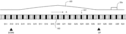
つぎに、EEPROM177のDMに登録した突起物セクタの位置情報とEEPROM177の制御テーブルに登録した操作情報を使用して突起物と磁気ヘッドの接触を回避しながらフォローイング動作をする方法を図12のフローチャートを参照して説明する。フォローイング動作のときは、シーク動作に比べて磁気ディスクと磁気ヘッドの相対的な速度が速くなるため、操作電圧を印加してから実際にフライング・ハイトが突起物との接触を回避できる程度まで上昇するときと、上昇してから基準フライング・ハイトまで戻るまでの圧電アクチュエータ制御系の応答時間を考慮する必要がある。
[Method of following operation]
Next, a method of performing the following operation while avoiding the contact between the protrusion and the magnetic head using the position information of the protrusion sector registered in the DM of the
図13は、図12の手順を実施するときのヘッド/スライダのフライング・ハイトと突起物の関係を示す図である。図13には、記録面13aの目標トラック187上にあるS11〜S31までのサーボ・セクタとそれらの間にある3つのデータ・セクタが示されている。磁気ディスク13の回転により目標トラック187は矢印A方向に移動しており、その上をヘッド/スライダ33aが浮上している。データ・セクタ183には突起物が存在しており、データ・セクタ183が依存するサーボ・セクタS20が突起物セクタとしてEEPROM177のDMに登録され、さらに突起物セクタS21の両側にそれぞれ連続する7個のサーボ・セクタS13〜S19、S21〜S27が欠陥セクタとしてEEPROM177のDMに登録されている。
FIG. 13 is a diagram showing the relationship between the flying height of the head / slider and the protrusion when the procedure of FIG. 12 is performed. FIG. 13 shows servo sectors S11 to S31 on the target track 187 on the
したがって、サーボ・セクタS13〜S27に依存するデータ・セクタは使用禁止にされておりユーザ・データは書き込まれていない。移動するトラック187と浮上しながら静止しているヘッド/スライダ33aの相対的位置関係を示すときには、目標トラック187の移動を停止させてヘッド/スライダ33aが矢印Aと反対方向に移動するように考えることができる。そのときのヘッド/スライダ33aのフライング・ハイトをライン185で示している。
Therefore, data sectors depending on the servo sectors S13 to S27 are prohibited from being used, and no user data is written. When indicating the relative positional relationship between the moving track 187 and the head /
ブロック401における前提状態として、突起物と磁気ヘッドとの接触の回避は、フォローイング動作中にMPU171がFH制御プログラムを実行し、EEPROM177の制御テーブルに登録された操作情報に基づいて生成した操作信号をACTドライバ165に送り、ACTドライバ165は操作量としての操作電圧を圧電アクチュエータに印加して制御量としての磁気ヘッドのフライング・ハイトを変化させることにより行うようになっている。また、磁気ディスク13、15の各記録面に対して図9の手順で突起物の検査が終了しており、EEPROM177には各記録面について検出された突起物のシリンダ・アドレス、セクタ・アドレス、およびヘッド番号からなる位置情報と、整数pおよびその補正値からなる操作情報が登録されている。さらに、ホスト・コンピュータからはリード・コマンドが送られ、指定されたアドレスのトラックに対するシーク動作が完了してフォローイング動作に移行する直前にあるものとする。
As a precondition in the
ブロック403では、再生ヘッド121aが目標トラック187に到達し、サーボ制御が速度制御から位置制御に移行して、フォローイング動作を開始する。フォローイング動作では、サーボ・データを再生したバースト信号からサーボ・コントローラが生成したPESによりMPU171が目標トラック187の中心に再生ヘッド121aを位置づけるようにVCMドライバ163に操作信号を供給して行う。ヘッド/スライダ33aは、図に示した位置では基準フライング・ハイトで浮上している。
In
ブロック405では、MPU171が目標トラック187が突起物トラックであるか否かをEEPROM177のDMを参照して判断する。ここでの目標トラックは再生ヘッドが位置づけられるトラックとそのとき同時に記録ヘッドが位置づけられるトラックの両方を含む。すなわち、ヨー角により再生ヘッド121aと記録ヘッド119aが異なるトラックに位置づけられているときは、それぞれのトラックが突起物トラックであるかどうかを判断する。再生ヘッド121aが位置づけられる目標トラック187とそれに対応した記録ヘッドが位置づけられる目標トラックが突起物トラックでない場合はブロック415に移行して基準フライング・ハイトで浮上したままフォローイング動作を行い、PESで計算したトラック上の位置の誤差が所定の範囲に入ったときにブロック417でデータの記録または再生を行う。
In
ブロック405で目標トラック187が再生ヘッド121aに対して突起物トラックであると判断した場合は、ブロック407に移行して、MPU171は各サーボ・セクタのセクタ・アドレスを読み取り、再生ヘッド121aを通過してゆく各サーボ・セクタが制御開始セクタS27か否かを判断する。制御開始セクタS27は、突起物セクタより回転方向側に連続して所定数だけ欠陥登録されたサーボ・セクタのうち先頭に位置するサーボ・セクタS27でありDMにフラグ設定されている。再生ヘッド121aが制御開始セクタS27のセクタ・アドレスを検出すると、MPU171は、制御テーブルに登録された操作情報を使用してACTドライバ165に対する操作信号を生成して供給する。
If it is determined in
操作信号を受け取ったACTドライバ165が圧電アクチュエータ41aに操作電圧を印加すると、圧電アクチュエータ41aの応答時間に従ってヘッド/スライダ33aのフライング・ハイトは基準フライング・ハイトから徐々に上昇してゆく。つづいてブロック411では、制御開始セクタS27が再生ヘッド121aを通過してから所定の時間が経過した時点でMPU171はACTドライバ165に対する操作信号の供給を停止する(ブロック411)。所定の時間は、制御開始セクタS27が再生ヘッド121aを通過してから突起物セクタS20が再生ヘッド121aに到達するまでの時間として設定されている。
When the
突起物セクタS20が再生ヘッド121aに到達した時点では、再生ヘッド121aのフライング・ハイトが、操作情報で指示された最も高い位置まで上昇している。再生ヘッド121aは突起物セクタS20のセクタ・アドレスを読み取ることができない場合もあるが、制御開始セクタS27が再生ヘッド121aを通過してからの経過時間を計測することで突起物セクタS20が再生ヘッドを通過するタイミングを正確に獲得することができる。MPU171がACTドライバ165に供給する操作信号を停止するタイミングは、突起物セクタS20の手前にあるサーボ・セクタS21またはS22から読み取ったセクタ・アドレスを利用して獲得してもよい。ヘッド/スライダ33aのフライング・ハイトは突起物セクタS20の位置で最高になったあとに基準フライング・ハイトに向かって下降し、サーボ・セクタS13で基準フライング・ハイトに戻る。ライン185はこのときのフライング・ハイトの変化の様子を示している。
When the projection sector S20 reaches the reproducing
S27からS13までのサーボ・セクタに依存する各データ・セクタはユーザ・データの記録に使用されないため、この間で磁気ヘッドのフライング・ハイトが上昇しても磁気ディスク装置の性能に支障はない。また、サーボ・セクタS20でのフライング・ハイトは、突起物と磁気ヘッドの接触を回避する最低の値となるように登録された操作情報に基づいているため、サーボ・データの再生が困難になるサーボ・セクタの数は最もフライング・ハイトが高い位置にある1個だけであり、フォローイング動作に支障はない。S27からS13までのサーボ・セクタの数は、一つのトラックに配置された全サーボ・セクタの数に対して数パーセント程度なので、ユーザはサーボ・セクタS12以降の残りのサーボ・セクタに依存するデータ・セクタを使用することができ記憶容量の維持を図ることができる。 Since each data sector depending on the servo sector from S27 to S13 is not used for user data recording, there is no problem in the performance of the magnetic disk apparatus even if the flying height of the magnetic head increases during this time. Also, since the flying height in the servo sector S20 is based on the operation information registered so as to be the lowest value that avoids contact between the protrusion and the magnetic head, it is difficult to reproduce the servo data. The number of servo sectors is only one at the position where the flying height is the highest, and there is no problem in the following operation. Since the number of servo sectors from S27 to S13 is about several percent of the total number of servo sectors arranged in one track, the user depends on the remaining servo sectors after servo sector S12. -Sectors can be used and storage capacity can be maintained.
以上は、リード・コマンド実行中のフライング・ハイトの制御例を示したが、ライト・コマンドの実行中でも同じようにして、突起物と記録ヘッドの接触を回避しながら記録動作を行うことができる。本実施例では、突起物セクタS20の前後に連続して配置された7個のサーボ・セクタを欠陥登録したが、欠陥登録をするサーボ・セクタの数はできるだけ少ない方が磁気ディスクの記憶容量の低下を防ぐために都合がよいので、磁気ディスクの回転速度と圧電アクチュエータの応答時間との関係に基づいて最適な個数を選択することが望ましい。応答時間の速いフライング・ハイト制御機構を使用すれば、欠陥登録するサーボ・セクタの数を減らすことができる。 In the above, an example of controlling the flying height during the execution of the read command has been shown. However, the recording operation can be performed while avoiding the contact between the protrusion and the recording head in the same manner even during the execution of the write command. In this embodiment, seven servo sectors arranged consecutively before and after the projection sector S20 are registered as defects. However, the smaller the number of servo sectors for which defects are registered, the smaller the storage capacity of the magnetic disk. Since it is convenient to prevent the decrease, it is desirable to select the optimum number based on the relationship between the rotational speed of the magnetic disk and the response time of the piezoelectric actuator. If a flying height control mechanism with a fast response time is used, the number of servo sectors to be registered as defects can be reduced.
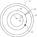
[シーク動作の他の方法の説明]
つぎに、シーク動作の他の方法について説明する。図10の手順では、シーク動作中に磁気ヘッドが通過するトラックの中に突起物トラックがあれば、磁気ヘッドと突起物とが接触する可能性があるか否かを判断しないで、突起物トラックの位置でフライング・ハイトを上昇させていた。突起物が同一トラック上に2つ以上存在することは実際にはほとんどないので、シーク動作において突起物トラックを基準フライング・ハイトで浮上する磁気ヘッドが通過しても突起物と磁気ヘッドが接触しない場合もある。
[Description of other methods of seek operation]
Next, another method of the seek operation will be described. In the procedure of FIG. 10, if there is a protrusion track in the track through which the magnetic head passes during the seek operation, it is not determined whether there is a possibility of contact between the magnetic head and the protrusion. The flying height was raised at the position. In reality, it is rare that there are two or more protrusions on the same track, so the protrusion and the magnetic head do not come into contact with each other even if the magnetic head that floats at the reference flying height passes through the protrusion track in the seek operation. In some cases.
いま、図14において、ヘッド/スライダ33aが現在トラック191に位置づけられており、ホスト・コンピュータからのリード/ライト・コマンドにより、目標トラック193までシーク動作をする場合を例に説明する。現在トラック191と目標トラック193との間には、突起物194が存在する突起物トラック192がある。MPU171は、シーク動作を開始する時点で現在トラック191から突起物トラック192にヘッド/スライダ33aが到達するまでの時間tを、その間に存在するトラックの数に基づいて計算する。あるいは、あらかじめ、通過するトラックの数と所要時間との関係を示したテーブルを用意してそれを参照してもよい。
Referring now to FIG. 14, an example will be described in which the head /
つぎに、シーク動作を開始する時点での突起物194の位置と磁気ディスク13の回転速度から時間tを経過したときの突起物194の位置を計算し、磁気ヘッドと突起物194が接触する可能性があるかどうかを計算する。計算の結果シーク動作を開始してから時間tを経過した時刻に突起物194がヘッド/スライダ33aの下に位置すると判断した場合は、MPU171は図10の手順で操作信号を生成してACTドライバ165に供給する。計算の結果、突起物194がヘッド/スライダ33aの下に位置しないと判断した場合は、MPU171は操作信号をACTドライバ165に供給しないで、基準フライング・ハイトを維持した状態でシーク動作を完了する。このように制御することで不必要なフライング・ハイトの調整をすることがなくなる。
Next, the position of the
これまで、圧電アクチュエータがHGAのロード・ビームに取り付けられた態様を例にして説明してきたが、圧電アクチュエータは特許文献1に示されているように、ヘッド/スライダに取り付けることもできる。図15は、特許文献1に示されている圧電アクチュエータ付のヘッド/スライダの外形図である。ヘッド/スライダ501は(A)に示すように親スライダ503と子スライダ505で構成され、両者には圧電アクチュエータ507が貼り付けられている。圧電アクチュエータ507に電圧を印加すると(B)に示すように、子スライダが変位してフライング・ハイトを変更することができるようになっている。さらに磁気ヘッドのフライング・ハイトを変化させる他の方法として、特開2003−168274号公報に記載されているような、ヘッド/スライダの中に2つのヒータを埋め込み、ヒータ電流で記録ヘッドと再生ヘッドの熱膨張量を個別に変化させてフライング・ハイトを制御する方法を採用することもできる。この場合のヒータはフライング・ハイト制御機構の一部を構成する。
Up to now, the embodiment in which the piezoelectric actuator is attached to the load beam of the HGA has been described as an example, but the piezoelectric actuator can also be attached to the head / slider as disclosed in
これまで本発明について図面に示した特定の実施の形態をもって説明してきたが、本発明は図面に示した実施の形態に限定されるものではなく、本発明の効果を奏する限り、これまで知られたいかなる構成であっても採用することができることはいうまでもないことである。 Although the present invention has been described with the specific embodiments shown in the drawings, the present invention is not limited to the embodiments shown in the drawings, and is known so far as long as the effects of the present invention are achieved. It goes without saying that any configuration can be adopted.
13、15 磁気ディスク
33a、33b、33c、33d ヘッド/スライダ
35a、35b、35c、35d ヘッド・ジンバル・アセンブリ
41a、41b、41c、41d 圧電アクチュエータ
119a 記録ヘッド
121a 再生ヘッド
133 サーボ・セクタ
135 データ領域
143a、143b、143c データ・セクタ
165 ACTドライバ(アクチュエータ・ドライバ)
181、194 突起物
13, 15
181, 194 Projection
Claims (20)
前記磁気ディスクにアクセスする磁気ヘッドを備えるヘッド/スライダと、
前記ヘッド/スライダを支持するヘッド支持機構と、
前記磁気ヘッドのフライング・ハイトを制御するFH制御機構と、
前記磁気ディスクの表面に存在する突起物の位置情報と、前記フライング・ハイトを制御して前記突起物と前記磁気ヘッドとの接触を回避するのに必要な前記FH制御機構の操作量に対応した操作情報を登録した記録媒体と、
前記位置情報と前記操作情報を参照して前記FH制御機構を制御し前記突起物と前記磁気ヘッドとの接触を回避するプロセッサと
を有する磁気ディスク装置。 A magnetic disk with multiple tracks defined;
A head / slider comprising a magnetic head for accessing the magnetic disk;
A head support mechanism for supporting the head / slider;
An FH control mechanism for controlling the flying height of the magnetic head;
Corresponding to the position information of the projections present on the surface of the magnetic disk and the operation amount of the FH control mechanism required to control the flying height to avoid contact between the projections and the magnetic head. A recording medium in which operation information is registered;
A magnetic disk device comprising: a processor that controls the FH control mechanism with reference to the position information and the operation information to avoid contact between the protrusion and the magnetic head.
磁気ディスクの表面に存在する突起物の位置情報と、前記フライング・ハイトを制御して前記突起物と前記磁気ヘッドとの接触を回避するのに必要な前記FH制御機構の操作量に対応した操作情報を提供するステップと、
基準フライング・ハイトでシーク動作を開始するステップと、
前記シーク動作において前記磁気ヘッドが前記突起物を含むトラックを通過する前に前記フライング・ハイトが前記基準フライング・ハイトよりも上昇し、前記磁気ヘッドが前記突起物を含むトラックを通過した後に前記フライング・ハイトが前記基準フライング・ハイトに戻るように前記位置情報と前記操作情報に基づいて前記FH制御機構を制御するステップと
を有する制御方法。 A method for controlling the flying height of the magnetic head in a magnetic disk device having an FH control mechanism for controlling the flying height of the magnetic head, comprising:
The operation corresponding to the operation amount of the FH control mechanism necessary to control the position information of the projections existing on the surface of the magnetic disk and the contact between the projections and the magnetic head by controlling the flying height. Providing information, and
Starting a seek operation at a reference flying height;
In the seek operation, the flying height rises above the reference flying height before the magnetic head passes the track including the protrusion, and the flying after the magnetic head passes the track including the protrusion. A control method comprising: controlling the FH control mechanism based on the position information and the operation information so that the height returns to the reference flying height.
磁気ディスクに試験データを書き込むステップと、
基準フライング・ハイトで磁気ヘッドを浮上させ前記試験データを再生するステップと、
前記再生するステップにおいて前記磁気ヘッドと前記磁気ディスク上の突起物の接触を検出し前記突起物の位置情報を前記参照テーブルに登録するステップと、
前記突起物と前記磁気ヘッドの接触を回避するのに必要な前記FH制御機構の操作量に対応した操作情報を前記参照テーブルに登録するステップと
を有する製造方法。 A method of manufacturing a magnetic disk device having an FH control mechanism for controlling flying height and a reference table that can be referred to by a processor,
Writing test data to the magnetic disk;
Flying the magnetic head at a reference flying height to reproduce the test data; and
Detecting the contact between the magnetic head and a protrusion on the magnetic disk in the reproducing step and registering the position information of the protrusion in the reference table;
And a step of registering operation information corresponding to an operation amount of the FH control mechanism necessary for avoiding contact between the protrusion and the magnetic head in the reference table.
18. The manufacturing method according to claim 17, further comprising the step of registering a predetermined number of servo sectors arranged on both sides of the servo sector on which the data sector including the protrusion is dependent as a defect.
Priority Applications (2)
| Application Number | Priority Date | Filing Date | Title |
|---|---|---|---|
| JP2005063419A JP2006252593A (en) | 2005-03-08 | 2005-03-08 | Magnetic disk device, control method and manufacturing method thereof |
| US11/372,064 US7457069B2 (en) | 2005-03-08 | 2006-03-08 | Magnetic disk drive with flying height control, control method, and manufacturing method |
Applications Claiming Priority (1)
| Application Number | Priority Date | Filing Date | Title |
|---|---|---|---|
| JP2005063419A JP2006252593A (en) | 2005-03-08 | 2005-03-08 | Magnetic disk device, control method and manufacturing method thereof |
Publications (2)
| Publication Number | Publication Date |
|---|---|
| JP2006252593A true JP2006252593A (en) | 2006-09-21 |
| JP2006252593A5 JP2006252593A5 (en) | 2008-04-03 |
Family
ID=36970573
Family Applications (1)
| Application Number | Title | Priority Date | Filing Date |
|---|---|---|---|
| JP2005063419A Withdrawn JP2006252593A (en) | 2005-03-08 | 2005-03-08 | Magnetic disk device, control method and manufacturing method thereof |
Country Status (2)
| Country | Link |
|---|---|
| US (1) | US7457069B2 (en) |
| JP (1) | JP2006252593A (en) |
Cited By (2)
| Publication number | Priority date | Publication date | Assignee | Title |
|---|---|---|---|---|
| KR100855973B1 (en) | 2007-01-24 | 2008-09-02 | 삼성전자주식회사 | Hard disk drive for controlling flying height of head and the method using the hard disk drive |
| JP2012089219A (en) * | 2010-10-22 | 2012-05-10 | Toshiba Corp | Disk storage device and defect management method |
Families Citing this family (20)
| Publication number | Priority date | Publication date | Assignee | Title |
|---|---|---|---|---|
| JP5064666B2 (en) * | 2005-08-24 | 2012-10-31 | エイチジーエスティーネザーランドビーブイ | Data storage device and user data write control method thereof |
| US7292401B2 (en) * | 2006-03-14 | 2007-11-06 | Hitachi Global Storage Technologies Netherlands B.V. | System and method for determining head-disk contact in a magnetic recording disk drive by magnetoresistive signal amplitude |
| JP2007293948A (en) * | 2006-04-21 | 2007-11-08 | Fujitsu Ltd | Information recording and reproducing device, head floating height control method, head floating control circuit |
| KR100856127B1 (en) * | 2007-02-12 | 2008-09-03 | 삼성전자주식회사 | Hard Disk Drive, Method For Controlling Flying On Demand Using Thermal Asperity Signal, And Recording Media For Computer Program Therefor |
| US7605996B2 (en) * | 2007-12-28 | 2009-10-20 | Hitachi Global Storage Technologies Netherlands B.V. | Method and system for detecting a change in a rotational velocity of a magnetic disk or a spindle coupled to the magnetic disk |
| US7804661B2 (en) * | 2008-12-01 | 2010-09-28 | Seagate Technology Llc | Microactuator control that avoids thermal asperities on disk surfaces |
| US7787201B2 (en) * | 2008-12-05 | 2010-08-31 | Hitachi Global Storage Technologies Netherlands B.V. | Method and apparatus for controlling fly-height of a perpendicular-magnetic-recording head in a hard disk drive |
| JP5043066B2 (en) * | 2009-05-28 | 2012-10-10 | 株式会社日立ハイテクノロジーズ | Optimal seek time measuring method considering magnetic head settling time and inspection apparatus using this measuring method |
| US8687313B2 (en) | 2011-06-23 | 2014-04-01 | Western Digital Technologies, Inc. | Disk drive mapping out data tracks to avoid thermal asperities |
| US8416650B2 (en) * | 2011-08-18 | 2013-04-09 | Tdk Corporation | Method for detecting protrusion height of magnetic head slider having thermally assisted head |
| US8699173B1 (en) * | 2011-09-01 | 2014-04-15 | Western Digital Technologies, Inc. | Disk drive detecting touchdown event by evaluating frequency response of a touchdown metric |
| US8694841B1 (en) | 2012-06-20 | 2014-04-08 | Western Digital Technologies, Inc. | Methods and devices for preventing potential media errors from growing thermal asperities |
| US8611031B1 (en) | 2012-08-16 | 2013-12-17 | Western Digital Technologies, Inc. | Methods and devices for adaptive margining |
| US8638649B1 (en) | 2013-01-07 | 2014-01-28 | Elwha, Llc | Topographic feedforward system |
| US8717859B1 (en) | 2013-01-07 | 2014-05-06 | Elwha, Llc | Reactionless control of a slider head |
| US8737183B1 (en) | 2013-01-07 | 2014-05-27 | Elwha, Llc | Topographic feedforward system |
| US8964326B1 (en) | 2013-12-02 | 2015-02-24 | Kabushiki Kaisha Toshiba | Disk storage apparatus and method for regulating head flying height before seek operation |
| CN104681044A (en) * | 2013-12-02 | 2015-06-03 | 株式会社东芝 | Magnetic Disk Apparatus And Touchdown Determination Method |
| US9251823B1 (en) * | 2014-12-10 | 2016-02-02 | Western Digital Technologies, Inc. | Data storage device delaying seek operation to avoid thermal asperities |
| US10388314B1 (en) * | 2018-04-12 | 2019-08-20 | Seagate Technology Llc | Adaptive configuration of thermal asperity guard bands |
Family Cites Families (8)
| Publication number | Priority date | Publication date | Assignee | Title |
|---|---|---|---|---|
| JPH1069747A (en) | 1996-08-28 | 1998-03-10 | Nec Corp | Magnetic disk device |
| JPH10233070A (en) | 1997-02-20 | 1998-09-02 | Sony Corp | Magnetic disk device |
| US5991113A (en) * | 1997-04-07 | 1999-11-23 | Seagate Technology, Inc. | Slider with temperature responsive transducer positioning |
| US6567229B1 (en) * | 1999-06-02 | 2003-05-20 | Maxtor Corporation | Avoiding asperities on a storage medium |
| US6501606B2 (en) * | 1999-12-02 | 2002-12-31 | Seagate Technology Llc | Fly height control for a read/write head over patterned media |
| US6757124B2 (en) * | 1999-12-03 | 2004-06-29 | Seagate Technology Llc | Actuator system for a disc drive using a piezoelectric assembly |
| JP3706015B2 (en) * | 2000-11-06 | 2005-10-12 | 株式会社日立グローバルストレージテクノロジーズ | Magnetic disk drive and control method thereof |
| US6504662B2 (en) * | 2000-12-28 | 2003-01-07 | Texas Instruments Incorporated | Apparatus for measuring and characterizing thermal asperities in a mass data storage device |
-
2005
- 2005-03-08 JP JP2005063419A patent/JP2006252593A/en not_active Withdrawn
-
2006
- 2006-03-08 US US11/372,064 patent/US7457069B2/en not_active Expired - Fee Related
Cited By (2)
| Publication number | Priority date | Publication date | Assignee | Title |
|---|---|---|---|---|
| KR100855973B1 (en) | 2007-01-24 | 2008-09-02 | 삼성전자주식회사 | Hard disk drive for controlling flying height of head and the method using the hard disk drive |
| JP2012089219A (en) * | 2010-10-22 | 2012-05-10 | Toshiba Corp | Disk storage device and defect management method |
Also Published As
| Publication number | Publication date |
|---|---|
| US7457069B2 (en) | 2008-11-25 |
| US20060203376A1 (en) | 2006-09-14 |
Similar Documents
| Publication | Publication Date | Title |
|---|---|---|
| JP2006252593A (en) | Magnetic disk device, control method and manufacturing method thereof | |
| US7158336B2 (en) | Window timing adjustment for spiral bursts | |
| JP4362491B2 (en) | Magnetic spacing control method of magnetic head, read / write circuit, and magnetic disk apparatus using the same | |
| US6445521B1 (en) | Write current optimization in a disc drive system | |
| JP4728929B2 (en) | Control device, control method, and storage device | |
| US6963458B2 (en) | Method and apparatus for reducing the servo position error signal non-linearity during self-servo writing irrespective of the head width | |
| JP4909878B2 (en) | Disk drive device and clearance adjustment method thereof | |
| US7583467B2 (en) | Hard disk drive apparatus, method to control flying on demand of hard disk drive apparatus using thermal asperity signal, and recording media for computer program thereof | |
| JP2009087405A (en) | Disk drive device, manufacturing method thereof, and method for setting heater power value for heater for adjusting clearance | |
| JP2010123231A (en) | Disk drive and method for controlling clearance | |
| US6963462B2 (en) | Servo detection control system, servo detection control method and hard disk drive | |
| JP2009157987A (en) | Method for adjusting recess depth of head slider and disk drive device | |
| JP2006073075A (en) | Magnetic disk device and its control method | |
| US6975478B2 (en) | Method for calibrating disk drive servo control system gain values during manufacturing | |
| US20050057835A1 (en) | Method and apparatus for optimizing write properties of magnetic head and defining magnetic head | |
| KR20070093332A (en) | Method of generating skew table for head and hard disk drive having processor for performing the method | |
| JP2006085832A (en) | Control method of recording current and magnetic disk apparatus | |
| US20030030928A1 (en) | Track mis-registration measurement for a disc drive | |
| JP2010067323A (en) | Disk drive and method for measuring clearance change | |
| JP2001189062A (en) | Disk storage device and servo data write-in method | |
| US7079347B2 (en) | Method and apparatus for providing a marker for adaptive formatting via a self-servowrite process | |
| US7649705B2 (en) | Data read retry with read timing adjustment for eccentrity of disc in data storage device | |
| JP2009129482A (en) | Test method and manufacturing method of disk drive device in consideration of manufacturing efficiency | |
| US20110075291A1 (en) | Disk drive controlled to detect head-disk interference | |
| US20100238585A1 (en) | Method of controlling flying height of magnetic head of hard disk drive |
Legal Events
| Date | Code | Title | Description |
|---|---|---|---|
| A521 | Request for written amendment filed |
Free format text: JAPANESE INTERMEDIATE CODE: A523 Effective date: 20080215 |
|
| A621 | Written request for application examination |
Free format text: JAPANESE INTERMEDIATE CODE: A621 Effective date: 20080218 |
|
| A761 | Written withdrawal of application |
Free format text: JAPANESE INTERMEDIATE CODE: A761 Effective date: 20090511 |