JP2013161515A - Disk-based storage device for performing head position control in accordance with detected intertrack interference - Google Patents
Disk-based storage device for performing head position control in accordance with detected intertrack interference Download PDFInfo
- Publication number
- JP2013161515A JP2013161515A JP2012250784A JP2012250784A JP2013161515A JP 2013161515 A JP2013161515 A JP 2013161515A JP 2012250784 A JP2012250784 A JP 2012250784A JP 2012250784 A JP2012250784 A JP 2012250784A JP 2013161515 A JP2013161515 A JP 2013161515A
- Authority
- JP
- Japan
- Prior art keywords
- read
- write head
- storage disk
- servo
- disk
- Prior art date
- Legal status (The legal status is an assumption and is not a legal conclusion. Google has not performed a legal analysis and makes no representation as to the accuracy of the status listed.)
- Withdrawn
Links
Images


Classifications
-
- G—PHYSICS
- G11—INFORMATION STORAGE
- G11B—INFORMATION STORAGE BASED ON RELATIVE MOVEMENT BETWEEN RECORD CARRIER AND TRANSDUCER
- G11B5/00—Recording by magnetisation or demagnetisation of a record carrier; Reproducing by magnetic means; Record carriers therefor
- G11B5/48—Disposition or mounting of heads or head supports relative to record carriers ; arrangements of heads, e.g. for scanning the record carrier to increase the relative speed
- G11B5/56—Disposition or mounting of heads or head supports relative to record carriers ; arrangements of heads, e.g. for scanning the record carrier to increase the relative speed with provision for moving the head support for the purpose of adjusting the position of the head relative to the record carrier, e.g. manual adjustment for azimuth correction or track centering
-
- G—PHYSICS
- G11—INFORMATION STORAGE
- G11B—INFORMATION STORAGE BASED ON RELATIVE MOVEMENT BETWEEN RECORD CARRIER AND TRANSDUCER
- G11B5/00—Recording by magnetisation or demagnetisation of a record carrier; Reproducing by magnetic means; Record carriers therefor
- G11B5/48—Disposition or mounting of heads or head supports relative to record carriers ; arrangements of heads, e.g. for scanning the record carrier to increase the relative speed
- G11B5/58—Disposition or mounting of heads or head supports relative to record carriers ; arrangements of heads, e.g. for scanning the record carrier to increase the relative speed with provision for moving the head for the purpose of maintaining alignment of the head relative to the record carrier during transducing operation, e.g. to compensate for surface irregularities of the latter or for track following
- G11B5/596—Disposition or mounting of heads or head supports relative to record carriers ; arrangements of heads, e.g. for scanning the record carrier to increase the relative speed with provision for moving the head for the purpose of maintaining alignment of the head relative to the record carrier during transducing operation, e.g. to compensate for surface irregularities of the latter or for track following for track following on disks
- G11B5/59627—Aligning for runout, eccentricity or offset compensation
-
- G—PHYSICS
- G11—INFORMATION STORAGE
- G11B—INFORMATION STORAGE BASED ON RELATIVE MOVEMENT BETWEEN RECORD CARRIER AND TRANSDUCER
- G11B19/00—Driving, starting, stopping record carriers not specifically of filamentary or web form, or of supports therefor; Control thereof; Control of operating function ; Driving both disc and head
- G11B19/02—Control of operating function, e.g. switching from recording to reproducing
- G11B19/04—Arrangements for preventing, inhibiting, or warning against double recording on the same blank or against other recording or reproducing malfunctions
- G11B19/041—Detection or prevention of read or write errors
- G11B19/045—Detection or prevention of read or write errors by detecting mistracking
-
- G—PHYSICS
- G11—INFORMATION STORAGE
- G11B—INFORMATION STORAGE BASED ON RELATIVE MOVEMENT BETWEEN RECORD CARRIER AND TRANSDUCER
- G11B21/00—Head arrangements not specific to the method of recording or reproducing
- G11B21/02—Driving or moving of heads
Landscapes
- Moving Of The Head To Find And Align With The Track (AREA)
- Digital Magnetic Recording (AREA)
Abstract
Description
本発明は、検出されたトラック間干渉に応じてヘッド位置制御を行うディスクベースの記憶装置に関する。 The present invention relates to a disk-based storage device that performs head position control in accordance with detected inter-track interference.
ハード・ディスク・ドライブ(HDD)のようなディスクベースの記憶装置は、広い種類の異なったタイプのデータ処理システムで不揮発性データ記憶を提供するために使用されている。代表的なHDDは、プラッタ(platter)と呼ばれる1つ以上の平らな円形の記憶ディスクを保持するスピンドル(spindle)を備えている。各記憶ディスクは、磁性材料の1つ以上の薄い層でコーティングされたアルミニウム又はガラスのような非磁性材料から作られた基板を備えている。動作の際、データは、ディスクが高速回転するときに位置決めアームによってディスク表面を横切って正確に移動される読み出し/書き込みヘッドによって、記憶ディスクのトラックから読み出され、これらのトラックに書き込まれる。 Disk-based storage devices such as hard disk drives (HDDs) are used to provide non-volatile data storage in a wide variety of different types of data processing systems. A typical HDD includes a spindle that holds one or more flat circular storage disks called platters. Each storage disk comprises a substrate made of a non-magnetic material such as aluminum or glass coated with one or more thin layers of magnetic material. In operation, data is read from and written to tracks on the storage disk by a read / write head that is accurately moved across the disk surface by a positioning arm as the disk rotates at high speed.
従来のHDDは、代表的に、読み出し/書き込みヘッド位置制御システムを用いており、このシステムでは、一般に「サーボ(servo)」マークと呼ばれる位置誤差検出領域が一定の間隔で記憶ディスク上に書き込まれる。これらのサーボ・マークは、サーボ・ライタ(writer)を使用してドライブ製造時に一度だけ書き込まれる。例として、ウェッジ(wedge)・サーボ配置では、サーボ・マークは、ディスクの周囲に分散した指定された放射状のウェッジの形態である。サーボ・ウェッジ間のデータ・ウェッジは、複数のデータ・セクタ(sector)を含み、トラック容量の大部分を消費する。サーボ・アルゴリズムは、ヘッド位置を検出するためにサーボ・ウェッジからのサーボ・マークを使用する。位置フィードバックは、データ・ウェッジの間利用できないので、サーボ・アルゴリズムは、代表的には、検出されたサーボ・マーク間のヘッド位置を補間しなければならない。サーボ・マークの他の配置も可能である。例えば、サーボ・マークは、サーボ・ウェッジに編成するのではなく、ディスク全体に均等に分散してもよい。 Conventional HDDs typically use a read / write head position control system, in which position error detection areas, commonly referred to as “servo” marks, are written onto a storage disk at regular intervals. . These servo marks are written only once at the time of drive manufacture using a servo writer. As an example, in a wedge servo arrangement, the servo marks are in the form of designated radial wedges distributed around the disk. The data wedge between the servo wedges includes a plurality of data sectors (sectors) and consumes most of the track capacity. The servo algorithm uses servo marks from the servo wedge to detect the head position. Since position feedback is not available during the data wedge, the servo algorithm typically must interpolate the head position between the detected servo marks. Other arrangements of servo marks are possible. For example, the servo marks may be evenly distributed throughout the disk rather than being organized into servo wedges.
HDDの動作中、ドライブ・ハードウェアは、読み出し/書き込みヘッド位置誤差の見積りを計算するためにサーボ・マークを読み取り、次にこの見積りは、読み出し/書き込みヘッドの半径方向の位置を維持するために、ファームウェア制御ループで使用される。サーボ・マーク専用のディスク空間は、ユーザ・データを記憶するために利用できないため、ディスク上に書き込まれるサーボ・マークの数は、読み出し/書き込みヘッド位置制御ループの帯域幅と、ドライブの容量との間のトレードオフを規定する。 During operation of the HDD, the drive hardware reads the servo marks to calculate an estimate of the read / write head position error, which in turn is used to maintain the radial position of the read / write head. Used in the firmware control loop. Since the dedicated disk space for servo marks is not available for storing user data, the number of servo marks written on the disk depends on the bandwidth of the read / write head position control loop and the capacity of the drive. Define the trade-off between.
HDDの記憶容量は増加し続けており、数テラバイト(TB)のデータを記憶できるHDDが現在利用できる。しかしながら、記憶容量の増加は、しばしば、トラック間干渉(Inter-Track Interference: ITI。以下単に「ITI」と称する。)及び読み出し/書き込みヘッド位置が重要な性能を制限する問題となるような、各記憶ディスク上により多くのトラックを収めるためのトラック寸法の縮小を必要とする。また、読み出し/書き込みヘッドの拡大縮小は制限されるので、結局、あるトラックに書き込むために使用される磁場は、隣接するトラックに影響を与え、そのためトラック密度を制限するであろう。 The storage capacity of HDDs continues to increase, and HDDs that can store several terabytes (TB) of data are currently available. However, increases in storage capacity are often associated with inter-track interference (ITI; hereinafter simply referred to as “ITI”) and read / write head position, which can be a significant performance limiting issue. It requires a reduction in track size to accommodate more tracks on the storage disk. Also, since the read / write head scaling is limited, eventually the magnetic field used to write to one track will affect adjacent tracks and thus limit track density.
HDD記憶容量をさらに増加させる試みでは、多数の記録技術が開発されている。例えば、シングルド(shingled)磁気記録(SMR)として知られる記録技術は、記憶ディスク上に以前に書き込まれた隣接するトラック上に所定のトラックを「瓦重ね(shingling)」することによって、HDDの記憶容量を増加させることを試みている。ビット・パターン化媒体(BPM)と呼ばれる別の記録技術では、磁気島の高密度トラックが記憶ディスクの表面上に予め形成され、データのビットがこれらの島のそれぞれに書き込まれる。それにもかかわらず、ITI及び読み出し/書き込みヘッド位置は、これらの及び他のHDD記録技術によっても重要な性能を制限する問題のままである。 In an attempt to further increase HDD storage capacity, a number of recording techniques have been developed. For example, a recording technology known as singled magnetic recording (SMR) is a technique for HDDs by “shingling” a given track onto an adjacent track previously written on a storage disk. Attempts to increase storage capacity. In another recording technique called Bit Patterned Medium (BPM), high density tracks of magnetic islands are pre-formed on the surface of the storage disk and bits of data are written to each of these islands. Nevertheless, ITI and read / write head positions remain a significant performance limiting issue with these and other HDD recording technologies.
HDDの性能に対するITIの悪影響は、読み出し時のITI打ち消し技術の適用によって、場合によっては対処することができる。このような打ち消し技術は、例えば、記憶ディスクから読み出されたデータにITI低減後処理を行うことが必要であることがある。このタイプの技術では、ITIに起因する読み出し信号ノイズを検出し、通常のデータ回復処理が適用される前に読み出し信号からそのノイズを打ち消すために、隣接するトラックに記憶された干渉データパターンについての情報が使用される。しかしながら、低減後処理は、代表的には、干渉データを記憶ディスクから読み出し、メモリに記憶することを必要とし、これは、アクセス時間のような他の性能尺度にも悪影響を及ぼすと同時に、HDDのコストと複雑さを増すことがある。 The adverse effect of ITI on HDD performance can be dealt with in some cases by applying ITI cancellation technology at the time of reading. Such a cancellation technique may require, for example, performing post-ITI reduction processing on data read from the storage disk. This type of technique detects the read signal noise due to ITI, and cancels the noise from the read signal before normal data recovery processing is applied. Information is used. However, post-reduction processing typically requires that the interference data be read from the storage disk and stored in memory, which adversely affects other performance measures such as access time, while at the same time HDD May increase cost and complexity.
隣接ビットの極性を考慮する方法での書き込み信号の補償前処理によって、ITIを低減することもできる。このタイプの書き込み補償技術は、本願の譲受人に譲渡され、参照により本明細書に組み込まれる、「Disk−Based Storage Device having Write Signal Compensation for Magnetization Polarity of Adjacent Bits」と表題が付けられた2011年9月30日に出願された米国特許出願第13/250,419号に開示されている。 ITI can also be reduced by pre-compensation processing of the write signal in a method that takes into account the polarity of adjacent bits. This type of write compensation technique is entitled “Disk-Based Storage Device Having Compensation for Adjudication of Advertisers Bits, 11”, assigned to the assignee of the present application and incorporated herein by reference. U.S. Patent Application No. 13 / 250,419 filed September 30.
本発明の例示的な実施形態は、検出されたITIに少なくとも部分的に基づいてヘッド位置を制御することによって向上した動作性能を示すHDD又は他のタイプのディスクベースの記憶装置を提供する。例えば、このような実施形態によるHDDは、ITI打ち消し処理の一部として、或いはその他の方法でITIを検出し、検出されたITIに関する情報を、検出されたITIに応じてヘッド位置を調節するヘッド位置コントローラに提供することができる。 Exemplary embodiments of the present invention provide HDDs or other types of disk-based storage devices that exhibit improved operational performance by controlling head position based at least in part on the detected ITI. For example, the HDD according to such an embodiment is a head that detects ITI as part of ITI cancellation processing or by other methods, and adjusts the position of the detected ITI according to the detected ITI. It can be provided to the position controller.
1つ以上の実施形態でのITIベースのヘッド位置制御は、従来のサーボベースのヘッド位置制御と併せて、又はその代わりに利用することができる。サーボ・フィードバックは、一般に、サーボ・マークが記憶ディスク上で一定の間隔で処理される場合にのみ利用可能であるのに対し、ヘッド位置制御のためのITIの使用は、ITIフィードバックがほとんど常に利用可能であるという点で、特に有利であることがある。 ITI-based head position control in one or more embodiments can be utilized in conjunction with or in place of conventional servo-based head position control. Servo feedback is generally only available when servo marks are processed at regular intervals on the storage disk, whereas the use of ITI for head position control is almost always used by ITI feedback. It may be particularly advantageous in that it is possible.
一実施形態では、HDD又は他のディスクベースの記憶装置は、記憶ディスクと、前記記憶ディスクからデータを読み出し、前記記憶ディスクにデータを書き込むように構成された読み出し/書き込みヘッドと、前記読み出し/書き込みヘッドに結合され、前記読み出し/書き込みヘッドから受けるデータ及び前記読み出し/書き込みヘッドに供給されるデータを処理し、前記記憶ディスクに対する前記読み出し/書き込みヘッドの位置決めを制御するように構成された制御回路網とを備えている。この実施形態の前記制御回路網は、前記読み出し/書き込みヘッドによって前記記憶ディスクの少なくとも所定のトラックから読み出された信号を、その信号中の前記記憶ディスクの少なくとも1つの他のトラックからのITIを検出するために処理するように構成されたITI検出器を備えている。前記制御回路網は、検出されたITIに応じて前記読み出し/書き込みヘッドの位置決めを調節するように構成されたITIベースのヘッド位置コントローラをさらに備えている。 In one embodiment, an HDD or other disk-based storage device includes a storage disk, a read / write head configured to read data from and write data to the storage disk, and the read / write A control network coupled to the head and configured to process data received from the read / write head and data supplied to the read / write head and control positioning of the read / write head relative to the storage disk And. In this embodiment, the control circuit network reads a signal read from at least a predetermined track of the storage disk by the read / write head, and an ITI from at least one other track of the storage disk in the signal. An ITI detector configured to process for detection is provided. The control circuitry further comprises an ITI-based head position controller configured to adjust the positioning of the read / write head in response to the detected ITI.
前記ITIベースのヘッド位置コントローラは、前記記憶ディスクの表面上のサーボ・マークのタイミング・パターンを検出することによってサーボ・タイミング情報を生成するサーボ・コントローラの一部であってもよく、そうでなければ、このようなサーボ・コントローラと共に動作するように構成されていてもよい。例えば、前記サーボ・コントローラは、前記ヘッド位置コントローラを組み込んでもよく、前記サーボ・タイミング情報と検出されたITIを特徴付ける情報の両方を利用して、前記読み出し/書き込みヘッドの位置決めを制御するように構成されていてもよい。しかしながら、上述したように、ITIベースのヘッド位置制御は、サーボ制御の使用を必要としない。 The ITI-based head position controller may be part of a servo controller that generates servo timing information by detecting the timing pattern of servo marks on the surface of the storage disk. For example, it may be configured to operate with such a servo controller. For example, the servo controller may incorporate the head position controller and is configured to control the positioning of the read / write head using both the servo timing information and information characterizing the detected ITI. May be. However, as described above, ITI-based head position control does not require the use of servo control.
本発明の実施形態の1つ以上は、ディスクベースの記憶装置の大幅な改善を提供する。例えば、検出されたITIに少なくとも部分的に基づいてヘッド位置を調節することによって、ヘッド位置を、ITIの存在下でのデータ回復のために最適化することができる。これは、従来のサーボ制御を使用してもしなくても、ヘッド位置精度を改善させることができ、それによって、低コストでよりよい性能が提供される。さらに、このような配置は、トラック・ピッチを減少させ、それによって、増加した記憶容量が所定の記憶ディスクに与えられる。 One or more of the embodiments of the present invention provide a significant improvement over disk-based storage devices. For example, by adjusting the head position based at least in part on the detected ITI, the head position can be optimized for data recovery in the presence of the ITI. This can improve head position accuracy with or without conventional servo control, thereby providing better performance at a lower cost. In addition, such an arrangement reduces the track pitch, thereby providing increased storage capacity to a given storage disk.
本発明の実施形態が、本明細書には、好例のディスクベースの記憶装置と、制御回路網と、関連するITIベースのヘッド位置制御技術と共に例示される。しかしながら、本発明のこれらの及び他の実施形態は、より一般的には、正確且つ効率的なヘッド位置制御の点で改善された性能が望まれるどのようなディスクベースの記憶装置にも適用可能であることを理解すべきである。追加の実施形態は、例示的な実施形態と共に特に示され記載されたもの以外の構成要素を使用して実施することができる。 Embodiments of the present invention are illustrated herein with exemplary disk-based storage devices, control circuitry, and associated ITI-based head position control techniques. However, these and other embodiments of the present invention are more generally applicable to any disk-based storage device where improved performance is desired in terms of accurate and efficient head position control. Should be understood. Additional embodiments may be implemented using components other than those specifically shown and described with the exemplary embodiments.
図1は、本発明の例示的な実施形態によるディスクベースの記憶装置100を示している。この実施形態の記憶装置100は、より具体的には、記憶ディスク110を含むハードディスクドライブ(HDD)を備えている。記憶ディスク110は、データを磁化状態の形態で記憶することができる1つ以上の磁気材料がコーティングされている記憶表面を有している。記憶ディスク110は、スピンドル120に接続されている。スピンドル120は、記憶ディスク110を高速で回転させるために、図には明示されていないスピンドル・モータによって駆動される。
FIG. 1 illustrates a disk-based
データは、位置決めアーム140に取り付けられた読み出し/書き込みヘッド130によって、記憶ディスク110から読み出され、記憶ディスク110に書き込まれる。記憶ディスク110の磁気表面上の読み出し/書き込みヘッドの位置は、電磁アクチュエータ150によって制御される。本実施形態の電磁アクチュエータ150と、その関連するドライバ回路網とは、より一般的には本明細書では記憶装置100の「制御回路網」と呼ばれるものの一部を構成するとみなすことができる。この実施形態のこのような制御回路網は、組立部品の反対側に配置され、したがって図1の斜視図では見ることができない追加の電子部品をさらに含むものとする。本明細書で使用される用語「制御回路網」は、したがって、ドライブ・エレクトロニクスと、信号処理エレクトロニクスと、関連する処理及びメモリ回路網とを、例として且つ限定されることなく含むように広く解釈されることを目的としており、記憶装置内の記憶ディスクの記憶表面に対する読み出し/書き込みヘッドの位置決めを制御するために利用される他の要素をさらに含むことができる。コネクタ160は、記憶装置100をホストコンピュータ又は他の関連する処理装置に接続するために使用される。
Data is read from the
図1は、単一の記憶ディスク110、読み出し/書き込みヘッド130及び位置決めアーム140の各々の1つの例のみを有する本発明の実施形態を示しているが、これは、単に説明的な例としてのものであり、本発明の代わりの実施形態は、1つ以上のこれら又は他のドライブ部品の複数の例を備えることができることを認識すべきである。例えば、あるこのような代わりの実施形態は、すべて同じ速度で回転するように同じスピンドルに取り付けられた複数の記憶ディスクと、複数の読み出し/書き込みヘッド及び1つ以上のアクチュエータに結合された複数の関連する位置決めアームとを備えることができる。所定の読み出し/書き込みヘッドは、この用語が本明細書では広く利用されているように、別個の読み出しヘッド及び書き込みヘッドの組み合わせの形態で実現されてもよい。より具体的には、本明細書で使用される用語「読み出し/書き込み」は、読み出し/書き込みヘッドが、読み出しヘッドのみ、書き込みヘッドのみ、読み出し及び書き込みの両方に使用される単一のヘッド、又は、別個の読み出しヘッド及び書き込みヘッドの組み合わせを備えることができるように、読み出し及び/又は書き込みとして広く解釈されることを目的としている。
FIG. 1 shows an embodiment of the present invention having only one example of each of a
また、図1に例示されている記憶装置100は、記憶装置のような従来の実施で一般に見られるタイプの1つ以上の要素を含む他の要素を、特別に図示されている要素に加えて、又はそれらの代わりに含むことができる。当業者にはよく理解されるこれら及び他の従来の要素は、本明細書では詳細には説明しない。図1に示す要素の特定の配置は、単に説明的な例として示されていることも理解すべきである。開示される技術は、より一般的には、記憶装置内に改善されたヘッド位置制御を与えることが望ましいどのような記憶装置用途にも、制限なしに適用可能である。当業者は、したがって、多種多様な他の記憶装置構成を、本発明の実施形態を実施する際に使用できることを認めるであろう。
Also, the
図2は、記憶ディスク110の記憶表面をより詳細に示している。例示されているように、記憶ディスク110の記憶表面は、複数の同心円状のトラック210を備えている。各トラックは、以降の検索のためのデータのブロックを記憶することができる複数のセクタ220に小分割されている。記憶ディスクの外側エッジに向かって配置されたトラックは、記憶ディスクの中心に向かって配置されたトラックと比べて、より大きな円周を有する。トラックはいくつかの環状ゾーン230にグループ化され、ゾーンのうちの所定のゾーン内のトラックは同じ数のセクタを有する。外側ゾーン内のこれらのトラックは、内側ゾーンに配置されたトラックより多くのセクタを有する。この例では、記憶ディスク110は、最も外側のゾーン230−0及び最も内側のゾーン230−Mを含むM+1のゾーンを備えているとする。
FIG. 2 shows the storage surface of the
記憶ディスク110の外側ゾーンは、内側ゾーンより高いデータ転送レートを提供する。これは、部分的には、本実施形態の記憶ディスクは、動作速度で回転させるために一旦加速されると、読み出し/書き込みヘッドの位置決めにかかわらず、一定の角又は放射速度で回転するが、内側ゾーンのトラックは外側ゾーンのトラックより小さい円周を有することによる。したがって、読み出し/書き込みヘッドが外側ゾーンのトラックの1つの上に位置する場合、読み出し/書き込みヘッドが内側ゾーンのトラックの1つの上に位置する場合より、記憶ディスクの所定の360度回転に対して、ディスク表面に沿ってより長い直線距離をカバーする。このような配置は、記憶ディスクの各360度回転に同じ時間が掛かるため、角速度一定(Constant Angular Velocity: CAV)を有すると呼ばれるが、CAV動作は本発明の実施形態の必要条件ではないことを理解すべきである。
The outer zone of
データ・ビット密度は、一般に、記憶ディスク110の記憶表面全体で一定であり、これは結果として、外側ゾーンでのより高いデータ転送レートを生じる。各外側ゾーンは、内側ゾーンより多くのデータを記憶するため、読み出し/書き込みヘッドは、外側ゾーン内のデータにアクセスするとき、所定のデータ量を読み出すために頻繁に移動する必要はない。したがって、内側ゾーン内のトラックに、又は内側ゾーン内のトラックからより、外側ゾーン内のトラックに、又は外側ゾーン内のトラックからのほうが、より高いレートでデータを転送することができる。
The data bit density is generally constant across the storage surface of the
したがって、記憶ディスクの最も外側の環状ゾーン230−0は、記憶ディスクの最も内側の環状ゾーン230−Mより高い平均データ転送レートを有する。平均データ転送レートは、所定の実施形態の最も外側の環状ゾーンと最も内側の環状ゾーンとの間で、2倍を超えて異なることがある。 Thus, the outermost annular zone 230-0 of the storage disk has a higher average data transfer rate than the innermost annular zone 230-M of the storage disk. The average data transfer rate may vary more than twice between the outermost annular zone and the innermost annular zone of a given embodiment.
単に例示としての一例の実施形態として、最も内側の環状ゾーンが、約1.0ギガビット毎秒(Gb/s)のデータ転送レートを有する一方で、最も外側の環状ゾーンは、約2.3Gb/sのデータ転送レートを有することができる。このような実施では、HDDは、より具体的には、500GBの合計記憶容量と、7200RPMのスピンドル速度とを有し、データ転送レートは、上記のように最も外側のゾーンの約2.3Gb/sから最も内側のゾーンの約1.0Gb/sまでの範囲にわたる。 By way of example only, the innermost annular zone has a data transfer rate of about 1.0 gigabit per second (Gb / s), while the outermost annular zone is about 2.3 Gb / s. Data transfer rate. In such an implementation, the HDD more specifically has a total storage capacity of 500 GB and a spindle speed of 7200 RPM, and the data transfer rate is about 2.3 Gb / s of the outermost zone as described above. It ranges from s to about 1.0 Gb / s in the innermost zone.
記憶ディスク110は、また、その記憶表面上に形成されたタイミング・パターンを含むものとする。このようなタイミング・パターンは、サーボ・アドレス・マーク(SAM)、又は、従来の方法で特定のセクタ内に形成された他のタイプのサーボ・マークを1組以上備えることができる。SAMは、したがって、本明細書ではより具体的にサーボ・マークと呼ばれるものの一例とみなすことができる。したがって、「タイミング・パターン」は、この用語が本明細書で使用されるとき、複数のサーボ・マークの配置をも含むことを目的としている。
The
記憶装置100は、内蔵読み出しチャネル・クロックと記憶ディスク110の表面上のサーボ・タイミング・パターンとの間の周波数差及び位相差を減少させるために、ディスク・ロックド・クロック(disk locked clock)(DLC)技術を実施することができる。これは、データ・セクタをより少ない周波数変化で書き込むことを可能にし、結果として、読み出しチャネルのクロック再生ループは、データ・セクタを読み出すとき、大きい周波数変化として処理する必要がない。代表的なDLC技術は、例えば、記憶ディスクの表面上のタイミング・パターンを提供するサーボ・マークの位置及び位相を測定することを含むことができる。HDD又は他のディスクベースの記憶装置におけるサーボ・マークの測定に関する追加の詳細は、本願の譲受人に譲渡され、参照により本明細書に組み込まれる、「Methods and Apparatus for Measuring Servo Address Mark Distance in a Read Channel Using Selective Fine Phase Estimate」と表題が付けられた米国特許第8,049,982号に見ることができる。
The
上述した実施形態で言及されている特定のデータ転送レート及び他の特徴は、単に例示の目的で提示されており、どのように制限するものとしても解釈されるべきではない。多種多様な他のデータ転送レート及び記憶ディスク構成を、他の実施形態で使用することができる。 The specific data transfer rates and other features mentioned in the embodiments described above are presented for illustrative purposes only and should not be construed as limiting in any way. A wide variety of other data transfer rates and storage disk configurations can be used in other embodiments.
本発明の実施形態が図3乃至5に関連して以下に説明され、これらの実施形態では、図1の記憶装置100は、ITIベースのヘッド位置制御に関する処理を実施するように構成される。これらの実施形態では、ITIベースのヘッド位置制御が、別の通常のサーボベースのヘッド位置制御と共に利用されているが、他の実施形態は、サーボベースのヘッド位置制御の使用なしで、ITIベースのヘッド位置制御を実施することができる。
Embodiments of the present invention are described below with respect to FIGS. 3-5, in which the
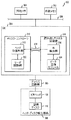
図3は、図1の記憶装置100の一部をより詳細に示している。この図では、記憶装置100は、プロセッサ300と、メモリ302と、システム・オン・チップ(SOC)304とを備えており、これらはバス306によって通信する。記憶装置は、SOC304と読み出し/書き込みヘッド130との間のインタフェースを提供するドライバ回路網305をさらに備えている。ドライバ回路網305は、例えば、プリアンプ及び他の関連するインタフェース回路網を備えることができる。メモリ302は、SOC304と、記憶装置100の他の部品とに関連した外部メモリであるが、それにもかかわらずこの記憶装置に内蔵されている。読み出し/書き込みヘッド130及び記憶ディスク100は、ヘッド・ディスク組立部品(HDA)308を構成するものとして、図3ではまとめて示されている。
FIG. 3 shows a part of the
本実施形態のSOC304は、読み出しチャネル回路網310及びディスク・コントローラ312を含んでおり、記憶ディスク110からデータを読み出し、記憶ディスク110にデータを書き込む際の読み出し/書き込みヘッド130の動作を指示する。読み出しチャネル回路網310及びディスク・コントローラ312は、バス306の一部を表すものとみなすことができる1つ以上のインタフェース接続部314によって互いに通信する。
The
バス306は、例えば、1つ以上の相互接続ファブリック(fabric)を備えることができる。このようなファブリックは、本実施形態では、例えば、参照により本明細書に組み込まれる、the Advanced Microcontroller Bus Architecture(AMBA)AXI v2.0 Specificationにより詳細に記載されているアドバンスド・エクステンシブル・インタフェース(Advanced eXtensible Interface)(AXI)ファブリックとして実装することができる。バスは、SOC304とドライバ回路網305との間のような、他のシステム部品間の通信をサポートするために使用することもできる。AXI相互接続は必須ではなく、多種多様な他のタイプのバス構成を本発明の実施形態で使用することができることを理解すべきである。
ディスク・コントローラ312は、読み出しチャネル回路網310内に実装されたITI検出器320からの検出されたITIに応答するヘッド位置コントローラ315を備えている。ヘッド位置コントローラ315は、サーボ回路網322によって提供されるサーボ・タイミング情報にも応答する。ITI検出器320は、一般に、読み出し/書き込みヘッド130によって記憶ディスク110の少なくとも所定のトラックから読み出された信号を、その信号中の記憶ディスクの少なくとも1つの他のトラックからの干渉を検出するために処理するように構成されている。本実施形態では、ITI検出器320によって処理される信号は、データ回復モジュール324によって提供されるが、他の実施形態では、他のタイプの信号を、これらの信号中のITIを検出するためにITI検出器によって利用することができる。
The
用語「トラック間干渉」は、広く解釈されることを目的としており、所定のトラックから読み出された信号中に1つ以上の他のトラックによって形成される干渉をも含むことができるというこの点について、注意すべきである。所定のトラックから読み出された信号中に干渉を形成する1つ以上の他のトラックは、1つ以上の非隣接トラックと同様に、又はその代わりに、1つ以上の隣接トラックを含むことがある。したがって、「トラック間干渉」は、この用語が本明細書で使用されるとき、1つ以上の非隣接トラックからの干渉と同様に、隣接トラック干渉も含むことを目的としている。 The term “inter-track interference” is intended to be broadly interpreted and in this respect can also include interference formed by one or more other tracks in a signal read from a given track. You should be careful about. One or more other tracks that form interference in a signal read from a given track may include one or more adjacent tracks in the same manner as, or instead of, one or more non-adjacent tracks. is there. Thus, “intertrack interference” is intended to include adjacent track interference as well as interference from one or more non-adjacent tracks, as the term is used herein.
本実施形態のヘッド位置コントローラ315は、ITI検出器320によって検出された干渉に応じて読み出し/書き込みヘッド130の半径方向の位置を調節するように構成されている。例えば、ヘッド位置コントローラ315は、ITI検出器320によって生成された1つ以上のITI測定指標(メトリック)を含む情報のような、検出された干渉を特徴付ける情報に少なくとも部分的に基づいて、読み出し/書き込みヘッドの位置決めを調節するように構成することができる。この実施形態では、ヘッド位置コントローラ315は、また、記憶ディスクの表面上のタイミング・パターンを検出するサーボ回路網322によって生成されるサーボ・タイミング情報に基づいて、読み出し/書き込みヘッド130の半径方向の位置を調節する。ここで、タイミング・パターンは、その表面上に形成された複数のサーボ・マークを備えている。ヘッド位置コントローラ315は、したがって、サーボ・タイミング情報と、検出されたITIを特徴付ける情報の両方を利用して読み出し/書き込みヘッド130の位置決めを制御するように構成された、別の通常のサーボ・コントローラを備えるとみなすことができる。
The
他の実施形態は、ITIベースのヘッド位置制御のみを実施することができる。用語「ITIベースのヘッド位置コントローラ」は、したがって、関連するサーボベースのヘッド位置制御を有する又は有さない配置を含む、検出されたITIが記憶装置内で読み出し/書き込みヘッドの位置を制御するために利用されるどのような配置をも含むことを目的としている。 Other embodiments may implement only ITI based head position control. The term “ITI-based head position controller” therefore includes a placement with or without an associated servo-based head position control for the detected ITI to control the position of the read / write head within the storage device. It is intended to include any arrangement used in the.
例として、サーボベースのヘッド位置制御は、サーボベースのヘッド位置測定値を、検出されたITI測定指標と相関させることによって、所定の実施形態のITIベースのヘッド位置制御と相互作用させることができる。相関パラメータは、記憶ディスク全体で一定であってもよく、記憶ディスクの異なったゾーンに関して変化してもよい。 As an example, servo-based head position control can interact with ITI-based head position control of certain embodiments by correlating servo-based head position measurements with detected ITI measurement metrics. . The correlation parameter may be constant throughout the storage disk or may vary for different zones of the storage disk.
ヘッド位置コントローラ315とITI検出器320は、それぞれディスク・コントローラ312と読み出しチャネル回路網310の中に実装されているように図3では例示的に示されているが、他の実施形態では、要素315と要素320は、他の方法で配置することができる。例えば、ITI検出器320は、ディスク・コントローラ312内に少なくとも部分的に実装することができ、又は、ヘッド位置コントローラ315は、読み出しチャネル回路網310内に少なくとも部分的に実装することができる。
Although
プロセッサ300と、メモリ302と、SOC304と、ドライバ回路網305とは、本明細書で利用される用語「制御回路網」の1つの可能な例をまとめて含むものとみなすことができる。制御回路網の多数の代わりの配置が、他の実施形態で使用することができ、このような配置は、部品300、302、304及び305の一部のみ、又は、1つ以上のこれらの部品の一部のみを含むことができる。例えば、SOC304それ自身は、「制御回路網」の一例とみなすことができる。上述したように、図3に示す実施形態の記憶装置100の制御回路網は、一般に、読み出し/書き込みヘッド130から受けるデータと、読み出し/書き込みヘッド130に供給されるデータとを処理し、記憶ディスク110に対する読み出し/書き込みヘッド130の位置決めを制御するように構成されている。
The
図3の記憶装置100におけるSOC304の特定の動作は、外部メモリ302に記憶されたコードを実行するプロセッサ300によって指示することができることに注意すべきである。例えば、プロセッサ300は、SOC304によって行われるITIベースのヘッド位置制御プロセスの少なくとも一部を行うためのメモリ302に記憶されたコードを実行するように構成することができる。したがって、記憶装置100のITI検出及びヘッド位置制御機能の少なくとも一部は、少なくとも部分的にはソフトウェア・コードの形態で実装することができる。
It should be noted that certain operations of the
外部メモリ302は、ランダム・アクセス・メモリ(RAM)又は読み出し専用メモリ(ROM)のような電子メモリをどのような組み合わせでも備えることができる。本実施形態では、制限することなしに、外部メモリ302がダブル・データ・レート(DDR)シンクロナス(Synchronous)・ダイナミック(Dynamic)RAM(SDRAM)の少なくとも一部として実装されるとする。メモリ302は、本明細書ではより一般的に「コンピュータ読み出し可能な記憶媒体」と呼ばれているものの一例である。このような媒体は、書き込み可能であってもよい。
The
本実施形態のSOC304は、単一の集積回路上に実装されていると仮定されているが、この集積回路は、プロセッサ300、メモリ302、ドライバ回路網305、及びバス306の部分をさらに含んでもよい。代わりに、プロセッサ300、メモリ302、ドライバ回路網305、及びバス306の部分は、HDDで使用されるように設計され、本明細書で開示されるようなITIベースのヘッド位置制御機能を提供するように適切に変更された別の通常の集積回路のような1つ以上の追加の集積回路の形態で、少なくとも部分的に実装することができる。
Although the
本発明の実施形態を組み込むように変更することができるSOC集積回路の一例は、本願の譲受人に譲渡され、参照により本明細書に組み込まれる、「Data Storage Drive with Reduced Power Consumption」と表題が付けられた米国特許第7,872,825号に開示されている。 An example of an SOC integrated circuit that can be modified to incorporate embodiments of the present invention is entitled “Data Storage Drive with Reduced Power Consumption”, assigned to the assignee of the present application and incorporated herein by reference. U.S. Pat. No. 7,872,825 attached.
プロセッサ、メモリ、又は所定の実施形態の他の記憶装置部品を実装するために使用することができる他のタイプの集積回路は、例えば、マイクロプロセッサ、ディジタル信号プロセッサ(DSP)、特定用途向け集積回路(ASIC)、フィールド・プログラマブル・ゲート・アレイ(Field Programmable Gate Array)(FPGA)、又は他の集積回路装置を含む。 Other types of integrated circuits that can be used to implement a processor, memory, or other storage device component of a given embodiment are, for example, microprocessors, digital signal processors (DSPs), application specific integrated circuits (ASIC), Field Programmable Gate Array (FPGA), or other integrated circuit device.
集積回路実装を含む実施形態では、複数の集積回路ダイを、ウエハの表面上に繰り返しパターンで形成することができる。各々のこのようなダイは、本明細書に記載されるような装置を含むことができ、他の構造又は回路を含むことができる。ダイは、ウエハから切断又はダイシングされ(diced)、次に集積回路としてパッケージされる。当業者は、ウエハをどのようにダイシングし、パッケージされた集積回路を製造するためにダイをどのようにパッケージするかを知っているであろう。このように製造された集積回路は、本発明の実施形態と考えられる。 In embodiments that include integrated circuit packaging, multiple integrated circuit dies can be formed in a repeating pattern on the surface of the wafer. Each such die can include devices as described herein and can include other structures or circuits. The dies are cut or diced from the wafer and then packaged as an integrated circuit. Those skilled in the art will know how to dice the wafer and how to package the die to produce a packaged integrated circuit. An integrated circuit manufactured in this way is considered an embodiment of the present invention.
本実施形態では記憶装置100の一部として示されているが、プロセッサ300とメモリ302の一方又は両方は、記憶装置がインストールされたホストコンピュータ又はサーバのような関連する処理装置内に少なくとも部分的に実装することができる。したがって、図3の実施形態の要素300及び302は、記憶装置100から分離しているとみなすこともでき、又は、記憶装置及びその関連する処理装置の両方とは別個の処理又はメモリ回路網部品を各々含む複合要素を表すとみなすこともできる。上述したように、プロセッサ300及びメモリ302の少なくとも一部は、本明細書で広く定義されている用語である「制御回路網」を備えるとみなすことができる。
Although shown in this embodiment as part of
図4は、記憶装置100内のITI検出器320及び関連するヘッド位置コントローラ315の1つの可能な実装のより詳細な図を示している。この実施形態では、サーボ・コントローラ400は、ITIベースのヘッド位置コントローラ402を使用してITIベースのヘッド位置制御を実施する。ITIベースのヘッド位置コントローラは、読み出しチャネル回路網310内のITI検出器320からITI測定指標(metric)404を受ける。サーボ・コントローラ400は、サーボ・プロセッサ410を使用するサーボベースのヘッド位置制御も実施する。本実施形態のサーボ・コントローラ400は、ヘッド位置コントローラ315とサーボ回路網322の組み合わせとみなすことができる。
FIG. 4 shows a more detailed view of one possible implementation of the
サーボ・コントローラ400は、また、タイミング制御モジュール412と、ルックアップ・テーブル(lookup table)414と、調整モータ制御モジュール415と、インタフェース・バス417と、スイッチ418とを含んでいる。タイミング制御モジュール412及びスイッチ418は、それぞれ本明細書ではより一般的にタイミング制御回路網及び切換回路網と呼ばれるものの例である。図4には明確に例示されていないが、ヘッド・ディスク組立部品308は、調整モータ制御モジュール415の出力に応じて、記憶ディスク110の表面に対する読み出し/書き込みヘッド130の半径方向の位置を変える調整モータを備えるものとする。本実施形態では、調整モータ制御モジュール415は、より具体的には、信号結合器を備えるボイス・コイル・モータ(Voice Coil Motor:VCM)制御モジュールの形態で実装されるが、他の実施形態では、サーボ・コントローラ400のこの部品を実装するために、多種多様な他の回路網配置を使用することができる。
インタフェース・バス417は、AMBAハイ・パフォーマンス・バス(High−performance Bus:AHB)を備えるように例示的に示されており、バス306の一部であってもよい。また、他の実施形態では、他のタイプのバス構成を使用することができる。
The
調整モータ制御モジュール415は、サーボ・プロセッサ410及びITIベースのヘッド位置コントローラ402からの個々の制御信号を受ける。ITIベースのヘッド位置コントローラ402からの制御信号は、1つ以上の読み出しチャネルITI測定指標404のような、検出された干渉を特徴付ける情報を利用してルックアップ・テーブル414をアドレス(address)することによって、少なくとも部分的に生成される。この制御信号は、より具体的には、調整モータ制御モジュール415によって読み出し/書き込みヘッド130に適用される所望のオフセット調整のオフセット信号指標を含んでいる。スイッチ418は、ITIベースのヘッド位置コントローラ402からの制御信号を、タイミング制御モジュール412の出力に応じて、オフセット信号線420を介して、調整モータ制御モジュール415の入力部に選択的に適用する。タイミング制御モジュール412及びITIベースのヘッド位置コントローラ402の動作は、インタフェース・バス417を介して伝送される1つ以上の信号を使用して、サーボ・プロセッサ410によって指示される。このような指示をコントローラ402及びタイミング制御モジュール412に与える際に、サーボ・プロセッサ410は、ヘッド・ディスク組立部品308からフィードバック経路422を経てプロセッサ410で受けた位置誤差信号(PES)フィードバックを利用する。
The adjustment
サーボ・プロセッサ410は、記憶ディスクの表面上のサーボ・マークを検出することによって生成されるサーボ・タイミング情報に基づいて読み出し/書き込みヘッド130の位置を制御するサーボ・アルゴリズムを実施する。モジュール415の出力におけるVCM制御信号は、各サーボ・マークが処理された後に更新することができ、ITIベースのヘッド位置コントローラ402によって決定される電流オフセットを反映するためにも更新される。このオフセットは、本実施形態では、検出されたサーボ・マーク間でほぼ連続的に、読み出し/書き込みヘッドの半径方向の位置を微調整するために利用される。この実施形態でのITIベースのヘッド位置制御は、したがって、サーボベースのヘッド位置制御を補う。ITIフィードバックは、データが記憶ディスクから読み出されるとき、ほぼ常に利用可能であるという点で、特に有用である。これは、一般に、サーボ・マークが記憶ディスク上で一定間隔で処理される場合にのみ利用可能なサーボ・フィードバックとは対照的である。
The
図4の実施形態では、検出器320は、ほぼ連続的にデータ信号からITIを抽出するように構成されていてもよい。ITI検出は、別の通常のITI打ち消しプロセスと併せて行ってもよいが、ITI打ち消しは、この実施形態では必須ではない。ITIは、浮上量(すなわち、データがディスクから読み出される、又はディスクに書き込まれるとき、ヘッドの磁気表面と記憶ディスクの磁気表面との間で維持される距離)及び環境要因(environment factors)のような、ヘッド位置変化の指標ではない要因(factors)を制御するために、検出器320の信号レベルに正規化することができる。ITI測定指標404は、正規化されたITI、又は、ITIの複合エネルギーのような他の関連する尺度を含んでもよい。これらの測定指標は、図に示されているようにサーボ・コントローラ400に提供される。ITI測定指標のこの伝送は、制御ループの特定の実装に応じて、ITIが記憶ディスクから読み出されたデータ信号中に検出されたとき、ほぼ連続的に生じるかもしれず、或いは、例えば、指定されたITIしきい値を超えたとき、又は、サーボ・コントローラ400によって要求されたとき、周期的に生じることがある。サーボ・コントローラは、一般に、ヘッドをデータ回復に最適な位置に維持するためにヘッド位置を調節するように構成されている。
In the embodiment of FIG. 4,
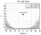
図5A及び5Bに関連して説明するように、データ回復に最適な位置は、読み出されているトラックの中心であるとは限らないことを理解すべきである。これらの図は、本発明の実施形態での、トラック中心に対する読み出し/書き込みヘッドのオフセットの関数としての、ITIの変化を例示している。この例のITIは、特定のタイプの測定指標、すなわち、複合エネルギー(E)によって表され、オフセットは、トラック・ピッチの割合として表される。各図は、公称原トラック・ピッチに対する異なった量のトラック・ピッチの変化(VTP)に対応している。 It should be understood that the optimal location for data recovery is not necessarily the center of the track being read, as will be described in connection with FIGS. 5A and 5B. These figures illustrate the change in ITI as a function of the read / write head offset relative to the track center in embodiments of the present invention. The ITI in this example is represented by a specific type of measurement index, namely composite energy (E), and the offset is expressed as a percentage of the track pitch. Each figure corresponds to a different amount of track pitch change (VTP) relative to the nominal original track pitch.
図5Aでは、トラック・ピッチは原(オリジナル)トラック・ピッチに対して10%減少しており、その結果、減少したトラック・ピッチは原トラック・ピッチの90%である。この図から、この場合、ITIが顕著になる前、ヘッド位置は約+15%又は−20%中心から離れていることがわかる。また、現在のトラックNの中心に対する負のオフセットが増加すると、隣接トラックN−1からのITIの量が増加し、トラックNの中心に対する正のオフセットが増加すると、隣接トラックN+1からのITIの量が増加することは明らかである。この例の最適なヘッド位置は、トラック中心に対する小さい負のオフセットであるように思われる。このようなオフセットは、上述したように、サーボ・プロセッサ410及びその関連するタイミング制御モジュール412の制御の下で、ITIベースのヘッド位置コントローラ402及びオフセット線420を経て、サーボ・コントローラ400によって導入することができる。この例のサーボ・コントローラは、一般に、ディスクから読み出されたデータ信号中のITIの複合エネルギーを最小化する負のオフセット位置にヘッドを維持しようとする。
In FIG. 5A, the track pitch is reduced by 10% relative to the original (original) track pitch, so that the reduced track pitch is 90% of the original track pitch. From this figure, it can be seen that in this case, the head position is about + 15% or -20% away from the center before ITI becomes significant. Further, when the negative offset with respect to the center of the current track N increases, the amount of ITI from the adjacent track N-1 increases, and when the positive offset with respect to the center of the track N increases, the amount of ITI from the adjacent track N + 1. It is clear that increases. The optimal head position in this example appears to be a small negative offset with respect to the track center. Such an offset is introduced by
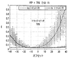
このようなオフセットの必要性は、トラック・ピッチが原トラック・ピッチに対して30%減少し、その結果、減少したトラック・ピッチが原トラック・ピッチの70%になっている図5Bの例では、さらに明らかである。この場合、ヘッドのその最適な位置からの比較的小さいずれによっても、相当な量のITIが結果として生じる。図5Aの例でのように、最適な位置はトラック中心に対応していない。さらに、この場合のサーボ・コントローラ400は、ディスクから読み出されたデータ信号中のITIの複合エネルギーを最小化する負のオフセット位置にヘッドを維持しようとする。
The need for such an offset is in the example of FIG. 5B where the track pitch is reduced by 30% relative to the original track pitch, resulting in a reduced track pitch of 70% of the original track pitch. It is even more obvious. In this case, any relatively small head from its optimal position will result in a substantial amount of ITI. As in the example of FIG. 5A, the optimum position does not correspond to the track center. Further, the
ITI複合エネルギーを使用してヘッド位置を推定することは、書き込みプロセスがかなりのITIを導入する場合、特に有効であることがあるが、それはこのような場合、ITIは、実際には、制御ループ性能を低下させるよりも、むしろ追加の位置推定情報を生成するからである。さらに、図4の実施形態でのようなITIベースのヘッド位置制御の使用は、ヘッド位置推定が、サーボベースのヘッド位置制御の場合のサーボ・マークにおけるのみではなく、データがディスクから読み出されるとき、ほぼ連続的に提供されることを可能にする。結果として、ITIベースのヘッド位置制御は、ディスク容量を犠牲にすることなく、非常により高い帯域幅の制御ループを提供する。 Estimating the head position using ITI composite energy may be particularly effective when the writing process introduces significant ITI, but in such cases, ITI is actually a control loop. This is because additional position estimation information is generated rather than lowering the performance. Furthermore, the use of ITI-based head position control as in the embodiment of FIG. 4 is such that head position estimation is not only at the servo mark in the case of servo-based head position control, but when data is read from the disk. Allows to be provided almost continuously. As a result, ITI-based head position control provides a much higher bandwidth control loop without sacrificing disk capacity.
上述したように、ITI測定指標404は、別の通常のITI打ち消しプロセスから得ることができる。このようなプロセスは、片側又は両側ITI打ち消しを含むことができる。片側ITI打ち消しは、単一の隣接トラックからのITIを検出し、打ち消す。この場合、サーボ・コントローラ400は、ヘッドが、ITIが抽出されていない反対側の隣接トラックに向かってドリフトしないことを保証するために、関連する隣接トラックの近くに位置するヘッドを維持するように構成することができる。両側(double-sided)ITI打ち消しは、両方の隣接トラックからのITIを検出し、打ち消す。この場合、サーボ・コントローラ400は、2つの隣接トラックから導入される合計のITIが最小化されるように、2つの隣接トラックの間にヘッドを位置決めするように構成することができる。
As described above, the
特に片側(single-sided)ITI打ち消しの場合、サーボベースのヘッド位置制御を可動域リミッタとして使用し、ヘッドが一方の隣接トラックから遠くに動き過ぎ、その結果、反対側の隣接トラックを侵害することから、ITIベースのヘッド位置制御を防ぐことができることに注意すべきである。 Especially in the case of single-sided ITI cancellation, using servo-based head position control as a range of motion limiter, the head moves too far away from one adjacent track, resulting in infringing on the opposite adjacent track Note that ITI-based head position control can be prevented.
所定の実施形態では、ITI複合エネルギーのようなITI測定指標は、各データ・セクタ内の各データ・ブロックに関して、それがディスクから読み出されたすぐ後に得ることができる。ブロック長は、ITI推定精度と制御ループ帯域幅との間のトレードオフを決定する。サーボ・コントローラ400は、現在のデータ・ブロックに関するこのITI複合エネルギーを、予め決められた範囲と比較し、ヘッド位置オフセットを予め決められた量だけ調節するように構成することができる。これらの動作は、少なくとも部分的にルックアップ・テーブル414を利用して実施することができる。ITI測定指標は、検出されたサーボ・マークに作用するサーボ・アルゴリズムによっても利用することができることに注意すべきである。
In certain embodiments, an ITI metric such as ITI composite energy can be obtained for each data block in each data sector immediately after it is read from the disk. Block length determines the trade-off between ITI estimation accuracy and control loop bandwidth.
上述したように、すべてのデータ・ブロックに関するようにほぼ連続的にITI測定指標を得る必要はなく、他の実施形態では、このような測定指標は、例えば、ITI複合エネルギーが規定された範囲外になったときにのみ、周期的にサーボ・コントローラ400によって取得し、処理することができる。
As mentioned above, it is not necessary to obtain ITI measurement metrics almost continuously as for all data blocks, and in other embodiments such measurement metrics are, for example, outside the defined range of ITI composite energy. Can only be acquired and processed by the
図3及び4に示す特定の回路網配置は、単に例として提示されており、本発明の他の実施形態は、他のタイプ及び配置の、追加の又は代わりの部品を利用することができることを認識すべきである。これらの他の実施形態の記憶装置の制御回路網は、ソフトウェアを実行するために利用される専用ハードウェア並びにプロセッサ又はメモリ資源を備えることができる。 The particular network arrangements shown in FIGS. 3 and 4 are presented by way of example only, and that other embodiments of the invention can utilize additional or alternative components of other types and arrangements. Should be recognized. The control circuitry of the storage device of these other embodiments may comprise dedicated hardware and processor or memory resources that are utilized to execute the software.
上述したように、記憶装置100の構成は、本発明の他の実施形態では変化してもよい。例えば、本発明の別の実施形態の記憶装置は、1つ以上の記憶ディスクに加えてフラッシュ・メモリを含むハイブリッドHDDを備えてもよい。
As described above, the configuration of the
特定の記憶ディスク構成及び記録機構は、本発明の他の実施形態では変化してもよいことも理解すべきである。例えば、シングルド(shingled)磁気記録(SMR)及びビット・パターン化媒体(BPM)のような記録技術は、本発明の1つ上の実施形態で使用することができる。 It should also be understood that the particular storage disk configuration and recording mechanism may vary in other embodiments of the invention. For example, recording techniques such as singled magnetic recording (SMR) and bit patterned media (BPM) can be used in the above embodiment of the present invention.
図6は、コンピュータ、サーバ、通信装置等であってもよいホスト処理装置602に結合されたディスクベースの記憶装置100を備える処理システム600を例示している。この図では別個の要素として示されているが、記憶装置100は、ホスト処理装置に組み込むことができる。記憶装置100に指示される読み出しコマンド及び書き込みコマンドのような命令は、図3に関連して上述したものと同様のプロセッサ及びメモリ素子を備えることができる処理装置602から来てもよい。
FIG. 6 illustrates a
複数のディスクベースの記憶装置100を、図7に例示されているような仮想記憶システム700に組み込むことができる。ストレージ(storage)仮想化システムとも呼ばれる仮想記憶システム700は、RAIDシステム704に結合された仮想記憶コントローラ702を例示的に備えており、ここでRAIDはリダンダント・アレイ・オブ・インデペンデント・ディスクス(Redundant Array of Independent Disks)を示す。RAIDシステムは、より具体的には、100−1,100−2,...100−Kと示されるK個の別個の記憶装置を備えており、それらの1つ以上は、本明細書で開示されているITIベースのヘッド位置制御機能を含むように構成されているとする。HDD又は本明細書で開示されているタイプの他のディスクベースの記憶装置を備えるこれら及び他の仮想記憶システムは、本発明の実施形態と考えられる。図6のホスト処理装置602は、仮想記憶システムの要素であってもよく、仮想記憶コントローラ702を組み込んでもよい。
Multiple disk-based
再び、上述した本発明の実施形態は、単に例示的なものであることを目的としていることを強調すべきである。例えば、他の実施形態は、異なるタイプ及び配置の、記憶ディスク、読み出し/書き込みヘッド、制御回路網、及び、説明した機能を実施するための他の記憶装置要素を使用することができる。また、ヘッド位置制御が検出されたITIに基づいて提供される特定の方法は、他の実施形態では変化してもよい。以下の請求項の範囲内にあるこれら及び多数の他の代わりの実施形態は、当業者には明らかであろう。 Again, it should be emphasized that the above-described embodiments of the present invention are intended to be exemplary only. For example, other embodiments may use different types and arrangements of storage disks, read / write heads, control circuitry, and other storage device elements to perform the functions described. Also, the particular method provided based on the ITI where head position control was detected may vary in other embodiments. These and many other alternative embodiments within the scope of the following claims will be apparent to those skilled in the art.
Claims (10)
前記制御回路網は、前記読み出し/書き込みヘッドから受けるデータ及び前記読み出し/書き込みヘッドに供給されるデータを処理し、前記記憶ディスクに対する前記読み出し/書き込みヘッドの位置決めを制御するように構成され、
前記制御回路網は、
前記読み出し/書き込みヘッドによって前記記憶ディスクの少なくとも所定のトラックから読み出された信号を、その信号中の前記記憶ディスクの少なくとも1つの他のトラックからの干渉を検出するために処理するように構成されたトラック間干渉検出器と、
前記検出された干渉に応じて前記読み出し/書き込みヘッドの前記位置決めを調節するように構成された、トラック間干渉ベースのヘッド位置コントローラとを備える、装置。 An apparatus comprising control circuitry adapted to couple to a read / write head configured to read data from a storage disk and write data to the storage disk,
The control circuitry is configured to process data received from the read / write head and data supplied to the read / write head and control positioning of the read / write head relative to the storage disk;
The control circuitry is
Configured to process a signal read from at least a predetermined track of the storage disk by the read / write head to detect interference from at least one other track of the storage disk in the signal. An inter-track interference detector,
And an inter-track interference based head position controller configured to adjust the positioning of the read / write head in response to the detected interference.
サーボ・プロセッサと、
前記読み出し/書き込みヘッド及び前記記憶ディスクを備えるヘッド・ディスク組立部品に結合するように適合された調整モータ制御モジュールとをさらに備え、
前記調整モータ制御モジュールは、前記サーボ・プロセッサ及び前記ヘッド位置コントローラからそれぞれの制御信号を受ける、請求項3に記載の装置。 The servo controller
A servo processor;
An adjustment motor control module adapted to couple to a head disk assembly comprising the read / write head and the storage disk;
4. The apparatus of claim 3, wherein the adjustment motor control module receives respective control signals from the servo processor and the head position controller.
前記サーボ・プロセッサに結合されたタイミング制御回路網と、
前記タイミング制御回路網の出力に応じて、前記ヘッド位置コントローラからの前記制御信号を前記調整モータ制御モジュールの入力部に選択的に適用するように構成された切換回路網とをさらに備える、請求項5に記載の装置。 The servo controller
A timing control network coupled to the servo processor;
And further comprising: a switching network configured to selectively apply the control signal from the head position controller to an input of the adjustment motor control module in response to an output of the timing control network. 5. The apparatus according to 5.
前記検出された干渉に応じて前記読み出し/書き込みヘッドの位置を調節するステップとを含む、方法。 Processing a signal read from at least a predetermined track of the storage disk by a read / write head to detect inter-track interference from at least one other track of the storage disk in the signal;
Adjusting the position of the read / write head in response to the detected interference.
前記記憶ディスクからデータを読み出し、前記記憶ディスクにデータを書き込むように構成された読み出し/書き込みヘッドと、
前記読み出し/書き込みヘッドに結合され、前記読み出し/書き込みヘッドから受けるデータ及び前記読み出し/書き込みヘッドに供給されるデータを処理し、前記記憶ディスクに対する前記読み出し/書き込みヘッドの位置決めを制御するように構成された制御回路網とを備える記憶装置であって、
前記制御回路網は、
前記読み出し/書き込みヘッドによって前記記憶ディスクの少なくとも所定のトラックから読み出された信号を、その信号中の前記記憶ディスクの少なくとも1つの他のトラックからの干渉を検出するために処理するように構成されたトラック間干渉検出器と、
前記検出された干渉に応じて前記読み出し/書き込みヘッドの前記位置決めを調節するように構成された、トラック間干渉ベースのヘッド位置コントローラとを備える、記憶装置。 At least one storage disk;
A read / write head configured to read data from the storage disk and write data to the storage disk;
Coupled to the read / write head and configured to process data received from the read / write head and data supplied to the read / write head and control positioning of the read / write head relative to the storage disk. A storage device comprising a control network,
The control circuitry is
Configured to process a signal read from at least a predetermined track of the storage disk by the read / write head to detect interference from at least one other track of the storage disk in the signal. An inter-track interference detector,
A storage device comprising: an inter-track interference based head position controller configured to adjust the positioning of the read / write head in response to the detected interference.
Applications Claiming Priority (2)
| Application Number | Priority Date | Filing Date | Title |
|---|---|---|---|
| US13/368,508 | 2012-02-08 | ||
| US13/368,508 US8773806B2 (en) | 2012-02-08 | 2012-02-08 | Disk-based storage device with head position control responsive to detected inter-track interference |
Publications (2)
| Publication Number | Publication Date |
|---|---|
| JP2013161515A true JP2013161515A (en) | 2013-08-19 |
| JP2013161515A5 JP2013161515A5 (en) | 2015-12-03 |
Family
ID=47832890
Family Applications (1)
| Application Number | Title | Priority Date | Filing Date |
|---|---|---|---|
| JP2012250784A Withdrawn JP2013161515A (en) | 2012-02-08 | 2012-11-15 | Disk-based storage device for performing head position control in accordance with detected intertrack interference |
Country Status (6)
| Country | Link |
|---|---|
| US (1) | US8773806B2 (en) |
| EP (1) | EP2626858A1 (en) |
| JP (1) | JP2013161515A (en) |
| KR (1) | KR20130091623A (en) |
| CN (1) | CN103247313B (en) |
| TW (1) | TW201333937A (en) |
Families Citing this family (8)
| Publication number | Priority date | Publication date | Assignee | Title |
|---|---|---|---|---|
| US8773806B2 (en) | 2012-02-08 | 2014-07-08 | Lsi Corporation | Disk-based storage device with head position control responsive to detected inter-track interference |
| JP5793474B2 (en) * | 2012-07-26 | 2015-10-14 | 株式会社東芝 | Recording / reproducing apparatus and recording / reproducing method |
| US8902534B2 (en) * | 2012-08-03 | 2014-12-02 | HGST Netherlands B.V. | Implementing track following using data characteristics for positional information |
| US8773789B1 (en) * | 2013-02-14 | 2014-07-08 | Lsi Corporation | In-channel channel optimization for hard-disc drive read/write chips |
| US9001442B2 (en) * | 2013-03-15 | 2015-04-07 | Seagate Technology Llc | Detection of adjacent track interference using size-adjustable sliding window |
| WO2015048677A1 (en) * | 2013-09-30 | 2015-04-02 | Marvell World Trade Ltd. | Generating position error signal based on data tracks for magnetic data storage |
| JP2015204123A (en) | 2014-04-15 | 2015-11-16 | 株式会社東芝 | Magnetic disc unit and data recording method |
| US10008229B2 (en) * | 2016-01-05 | 2018-06-26 | Western Digital Technologies, Inc | Implementing enhanced track following during read back using head asymmetry metrics in hard disk drives |
Family Cites Families (24)
| Publication number | Priority date | Publication date | Assignee | Title |
|---|---|---|---|---|
| JPS60201556A (en) * | 1984-03-22 | 1985-10-12 | Toshiba Corp | Tracking device |
| JPS63217556A (en) * | 1987-03-06 | 1988-09-09 | Pioneer Electronic Corp | Rotary head type digital audio reproducing device |
| US5041926A (en) | 1989-11-13 | 1991-08-20 | Hewlett-Packard Company | Track position syncopation cancellation in a disk drive |
| US5398140A (en) | 1991-08-06 | 1995-03-14 | R-Byte, Inc. | Digital data tape storage automatic track follower system |
| JPH05174456A (en) * | 1991-12-20 | 1993-07-13 | Sony Corp | Recording and reproducing device |
| US6411452B1 (en) | 1997-03-11 | 2002-06-25 | Western Digital Technologies, Inc. | Disk drive employing read error tolerant sync mark detection |
| US6115198A (en) * | 1997-10-29 | 2000-09-05 | Cirrus Logic, Inc. | PR4 sampled amplitude read channel for detecting user data and embedded servo data |
| US7126890B2 (en) * | 2002-08-26 | 2006-10-24 | Bae Systems Information And Electronic Systems Integration Inc | Multitrack readback and multiuser detection for disk drives |
| US6826140B2 (en) * | 2002-08-26 | 2004-11-30 | Bae Systems Information And Electronic Systems Integration Inc | Multichannel digital recording system with multi-user detection |
| US7116514B2 (en) | 2003-10-20 | 2006-10-03 | Quantum Corporation | Methods and systems for magnetic recording |
| US7068459B1 (en) * | 2004-09-20 | 2006-06-27 | Western Digital Technologies, Inc. | Adjusting track density by changing PES algorithm when servo writing a disk drive from spiral tracks |
| JP2007048335A (en) | 2005-08-05 | 2007-02-22 | Hitachi Global Storage Technologies Netherlands Bv | Disk drive |
| JP2008027499A (en) | 2006-07-19 | 2008-02-07 | Lenovo Singapore Pte Ltd | Magnetic recording system, magnetic recording method, and magnetic recording program |
| JP4745172B2 (en) | 2006-08-29 | 2011-08-10 | 東芝ストレージデバイス株式会社 | Control device and storage device |
| US7567397B2 (en) | 2006-09-11 | 2009-07-28 | Hitachi Global Storage Technologies Netherlands B.V. | Adjacent Track Interference (ATI) identification methodology |
| JP4331202B2 (en) * | 2006-12-25 | 2009-09-16 | 株式会社東芝 | Playback apparatus and playback method |
| US7760455B2 (en) | 2007-04-19 | 2010-07-20 | Samsung Electronics Co., Ltd. | Method and apparatus improving prevention of off-track writing in a hard disk drive |
| US8000213B2 (en) * | 2007-06-29 | 2011-08-16 | Panasonic Corporation | Optical disc recording/reproducing apparatus |
| KR101340715B1 (en) | 2007-08-20 | 2013-12-12 | 에이저 시스템즈 엘엘시 | Data storage drive with reduced power consumption |
| CN101436410A (en) | 2007-11-12 | 2009-05-20 | 深圳易拓科技有限公司 | Method for eliminating interference formed by HDD irregular track |
| US7948708B2 (en) | 2009-03-23 | 2011-05-24 | Carnegie Mellon University | Simultaneous bit pattern determination and head positional information detection on patterned media |
| US8049982B1 (en) | 2010-07-30 | 2011-11-01 | Lsi Corporation | Methods and apparatus for measuring servo address mark distance in a read channel using selective fine phase estimate |
| US8804260B2 (en) * | 2010-09-13 | 2014-08-12 | Lsi Corporation | Systems and methods for inter-track interference compensation |
| US8773806B2 (en) | 2012-02-08 | 2014-07-08 | Lsi Corporation | Disk-based storage device with head position control responsive to detected inter-track interference |
-
2012
- 2012-02-08 US US13/368,508 patent/US8773806B2/en active Active
- 2012-10-02 TW TW101136382A patent/TW201333937A/en unknown
- 2012-10-30 CN CN201210422992.8A patent/CN103247313B/en active Active
- 2012-11-07 KR KR1020120125139A patent/KR20130091623A/en not_active Application Discontinuation
- 2012-11-15 JP JP2012250784A patent/JP2013161515A/en not_active Withdrawn
-
2013
- 2013-02-07 EP EP13154452.0A patent/EP2626858A1/en not_active Ceased
Also Published As
| Publication number | Publication date |
|---|---|
| CN103247313B (en) | 2016-08-03 |
| TW201333937A (en) | 2013-08-16 |
| KR20130091623A (en) | 2013-08-19 |
| US8773806B2 (en) | 2014-07-08 |
| EP2626858A1 (en) | 2013-08-14 |
| CN103247313A (en) | 2013-08-14 |
| US20130201579A1 (en) | 2013-08-08 |
Similar Documents
| Publication | Publication Date | Title |
|---|---|---|
| JP2013161515A (en) | Disk-based storage device for performing head position control in accordance with detected intertrack interference | |
| US8654471B2 (en) | Disk-based storage device having write signal compensation for magnetization polarity of adjacent bits | |
| US7760455B2 (en) | Method and apparatus improving prevention of off-track writing in a hard disk drive | |
| JP6699905B2 (en) | Magnetic disk device and recording area setting method | |
| US20130038959A1 (en) | Disk drive writing spiral tracks on a slave surface using repeatable runout compensation for a master surface | |
| US7864476B2 (en) | Low track-per-inch (TPI) zone with reduced need for adjacent-track-erasure (ATE) refresh | |
| US7880992B2 (en) | Phase detector that compensates for frequency variation induced bias in phases of servo burst fields | |
| US20110075286A1 (en) | System, method and apparatus for determining track pitch in a hard disk drive to satisfy the requirements of both off-track capacity and adjacent track erasure | |
| JPH1050014A (en) | Self-servo writing method for maintaining reference level in dynamic range | |
| JP4644356B2 (en) | Servo write system for magnetic disk device and magnetic recording / reproducing device | |
| JP2008257839A (en) | Multiple direction self servo writing to disk drive | |
| US20100290153A1 (en) | Servo processors that alternately control head positioning relative to sequential servo patterns | |
| US8755142B2 (en) | Magnetic recording disk drive with method for data preservation during high track misregistration (TMR) environment | |
| US7567404B1 (en) | Method for measuring actuator velocity during self-servo-write | |
| US8902539B1 (en) | Data storage device reducing seek power consumption | |
| US7423832B2 (en) | Controlling head heating based on upcoming data sector write pattern | |
| US20130201576A1 (en) | Storage device having calibration circuitry providing programmable phase update values | |
| JP2008243352A (en) | Disk drive apparatus, electronic circuit for disk drive apparatus and powering method therefor | |
| US7027244B2 (en) | Systems for self-servowriting using write-current variation | |
| JP2002269703A (en) | Magnetic disk device of perpendicular magnetic recording system | |
| US11776570B2 (en) | Reducing non-coherent repeatable runout in two-dimensional magnetic recording disk drives | |
| US8711505B2 (en) | Storage device having clock adjustment circuitry with firmware-based predictive correction | |
| US7149043B2 (en) | Methods for self-servowriting using write-current variation | |
| JP2010044833A (en) | Method of detecting head position and recording medium drive unit | |
| US9842617B1 (en) | Electronic system with head management mechanism and method of operation thereof |
Legal Events
| Date | Code | Title | Description |
|---|---|---|---|
| RD03 | Notification of appointment of power of attorney |
Free format text: JAPANESE INTERMEDIATE CODE: A7423 Effective date: 20140812 |
|
| RD04 | Notification of resignation of power of attorney |
Free format text: JAPANESE INTERMEDIATE CODE: A7424 Effective date: 20140828 |
|
| RD04 | Notification of resignation of power of attorney |
Free format text: JAPANESE INTERMEDIATE CODE: A7424 Effective date: 20140829 |
|
| A711 | Notification of change in applicant |
Free format text: JAPANESE INTERMEDIATE CODE: A711 Effective date: 20150522 |
|
| A521 | Request for written amendment filed |
Free format text: JAPANESE INTERMEDIATE CODE: A523 Effective date: 20151014 |
|
| A621 | Written request for application examination |
Free format text: JAPANESE INTERMEDIATE CODE: A621 Effective date: 20151014 |
|
| A761 | Written withdrawal of application |
Free format text: JAPANESE INTERMEDIATE CODE: A761 Effective date: 20160706 |