KR20130046576A - Apparatus for controlling upward movement of material - Google Patents
Apparatus for controlling upward movement of material Download PDFInfo
- Publication number
- KR20130046576A KR20130046576A KR1020110111044A KR20110111044A KR20130046576A KR 20130046576 A KR20130046576 A KR 20130046576A KR 1020110111044 A KR1020110111044 A KR 1020110111044A KR 20110111044 A KR20110111044 A KR 20110111044A KR 20130046576 A KR20130046576 A KR 20130046576A
- Authority
- KR
- South Korea
- Prior art keywords
- upward
- contact
- unit
- tip
- rolling
- Prior art date
Links
Images


Classifications
-
- B—PERFORMING OPERATIONS; TRANSPORTING
- B21—MECHANICAL METAL-WORKING WITHOUT ESSENTIALLY REMOVING MATERIAL; PUNCHING METAL
- B21B—ROLLING OF METAL
- B21B37/00—Control devices or methods specially adapted for metal-rolling mills or the work produced thereby
- B21B37/68—Camber or steering control for strip, sheets or plates, e.g. preventing meandering
-
- B—PERFORMING OPERATIONS; TRANSPORTING
- B21—MECHANICAL METAL-WORKING WITHOUT ESSENTIALLY REMOVING MATERIAL; PUNCHING METAL
- B21B—ROLLING OF METAL
- B21B33/00—Safety devices not otherwise provided for; Breaker blocks; Devices for freeing jammed rolls for handling cobbles; Overload safety devices
-
- B—PERFORMING OPERATIONS; TRANSPORTING
- B21—MECHANICAL METAL-WORKING WITHOUT ESSENTIALLY REMOVING MATERIAL; PUNCHING METAL
- B21B—ROLLING OF METAL
- B21B37/00—Control devices or methods specially adapted for metal-rolling mills or the work produced thereby
- B21B37/46—Roll speed or drive motor control
-
- B—PERFORMING OPERATIONS; TRANSPORTING
- B21—MECHANICAL METAL-WORKING WITHOUT ESSENTIALLY REMOVING MATERIAL; PUNCHING METAL
- B21B—ROLLING OF METAL
- B21B37/00—Control devices or methods specially adapted for metal-rolling mills or the work produced thereby
- B21B37/72—Rear end control; Front end control
-
- B—PERFORMING OPERATIONS; TRANSPORTING
- B21—MECHANICAL METAL-WORKING WITHOUT ESSENTIALLY REMOVING MATERIAL; PUNCHING METAL
- B21B—ROLLING OF METAL
- B21B38/00—Methods or devices for measuring, detecting or monitoring specially adapted for metal-rolling mills, e.g. position detection, inspection of the product
-
- B—PERFORMING OPERATIONS; TRANSPORTING
- B21—MECHANICAL METAL-WORKING WITHOUT ESSENTIALLY REMOVING MATERIAL; PUNCHING METAL
- B21B—ROLLING OF METAL
- B21B2273/00—Path parameters
- B21B2273/12—End of product
- B21B2273/14—Front end or leading end
-
- B—PERFORMING OPERATIONS; TRANSPORTING
- B21—MECHANICAL METAL-WORKING WITHOUT ESSENTIALLY REMOVING MATERIAL; PUNCHING METAL
- B21B—ROLLING OF METAL
- B21B2275/00—Mill drive parameters
- B21B2275/02—Speed
- B21B2275/04—Roll speed
- B21B2275/05—Speed difference between top and bottom rolls
Abstract
Description
본 발명은 소재 상향 제어 장치에 관한 것으로서, 더욱 상세하게는 압연부에서 송출되는 소재 선단부의 상향 시 이를 교정하여 제품의 품질을 향상시킬 수 있는 소재 상향 제어 장치에 관한 것이다.
The present invention relates to a material upward control device, and more particularly, to a material upward control device that can improve the quality of the product by correcting this when the top of the material sent out from the rolling section.
일반적인 철강 제조는 용선을 생산하는 제선 공정, 용선에서 불순물을 제거하는 제강 공정, 액체 상태의 철이 고체로 되는 연속주조 공정, 철을 강판이나 선재로 만드는 압연 공정으로 이루어진다. Typical steelmaking consists of a steelmaking process to produce molten iron, a steelmaking process to remove impurities from molten iron, a continuous casting process to make solid iron into solid, and a rolling process to make iron into steel or wire.
압연 공정은 연속주조 공정에서 생산된 슬래브, 블룸 등의 중간 소재를 회전하는 여러 개의 롤러 사이를 통과시켜 연속적인 힘을 가하여 늘리거나 얇게 만드는 과정을 말하며 크게 열간 압연과 냉간 압연으로 나뉜다.The rolling process is a process of passing an intermediate material such as a slab, a bloom, etc. produced in a continuous casting process through a plurality of rotating rollers and applying a continuous force to increase or decrease the thickness thereof. The rolling process is roughly classified into hot rolling and cold rolling.
본 발명의 배경기술은 대한민국 공개특허공보 2004-0105892호(2004. 12. 17 공개, 발명의 명칭 : 슬라브의 상향 교정 기능이 구비된 디스케일링용 냉각수차단장치)에 개시되어 있다.
Background art of the present invention is disclosed in Republic of Korea Patent Publication No. 2004-0105892 (published Dec. 17, 2004, the name of the invention: descaling cooling water blocking device equipped with the upward calibration function of the slab).
본 발명은 압연부에서 송출되는 소재 선단부의 상향 시 이를 교정하여 제품의 품질을 향상시킬 수 있는 소재 상향 제어 장치를 제공하는데 그 목적이 있다.
An object of the present invention is to provide a material upward control device that can improve the quality of the product by correcting this when the top of the material sent out from the rolling section.
본 발명의 일 측면에 따른 소재 상향 제어 장치는: 소재를 압연하는 압연부; 상기 압연부의 후방에 배치되고, 상기 압연부에서 송출되는 상기 소재를 이송시키는 이송롤러부; 상기 이송롤러부의 상방에 배치되고, 상기 이송롤러부 상을 이동하는 상기 소재의 선단부와 접촉하여 상기 소재 선단부의 상향을 교정하며, 상기 소재 선단부와의 접촉 시 발생하는 충격을 흡수하는 상향교정부; 상기 소재의 이송 경로 상에 배치되고, 상기 소재 선단부의 상향 시 상기 소재 선단부와 접촉되어 상기 소재 선단부의 상향을 감지하는 접촉감지부; 및 상기 접촉감지부와 연결되어 상기 접촉감지부에서 감지된 상기 소재 선단부의 상향량에 따라 상기 압연부의 구동을 제어하는 제어부를 포함한다.Device upward control device according to an aspect of the present invention comprises: a rolling unit for rolling the material; A conveying roller part disposed at the rear of the rolling part to convey the material sent from the rolling part; An upward correction part disposed above the feed roller part to correct an upward direction of the material tip part by contacting the tip part of the material moving on the feed roller part, and absorbing an impact generated when contacting the material tip part; A contact sensing unit disposed on the transport path of the raw material and contacting the raw material tip when the raw material tip is upward to detect the upward of the raw material tip; And a control unit connected to the contact detecting unit to control driving of the rolling unit according to an upward amount of the material tip detected by the contact detecting unit.
바람직하게는, 상기 상향교정부는, 고정프레임; 상기 고정프레임과 힌지부에 의해 회전 가능하게 결합되고, 상기 소재의 선단부와 접촉되는 회동프레임; 및 일측이 상기 고정프레임에 고정되고, 타측이 상기 회동프레임에 고정되어 상기 회동프레임을 탄성 지지하는 탄성부재를 포함한다.Preferably, the upward correction portion, the fixed frame; A rotatable frame rotatably coupled to the fixed frame and the hinge portion and in contact with the front end portion of the material; And an elastic member having one side fixed to the fixed frame and the other side fixed to the rotating frame to elastically support the rotating frame.
더 바람직하게는, 상기 상향교정부는, 상기 회동프레임에 회전 가능하게 설치되는 롤러를 더 포함하고, 상기 롤러의 하단은 상기 회동프레임의 하면보다 하측에 배치되어 상기 소재 선단부의 상향 시 상기 소재 선단부와 상기 회동프레임의 접촉을 차단한다.More preferably, the upward corrector further includes a roller rotatably installed on the pivot frame, and a lower end of the roller is disposed below the lower surface of the pivot frame so that the material tip portion is upward when the material tip portion is upward. Block the contact of the rotating frame.
더 바람직하게는, 상기 롤러는 상기 소재의 이송 방향을 따라 상기 회동프레임에 복수개가 설치된다.More preferably, a plurality of rollers are installed in the rotation frame along the conveying direction of the material.
더 바람직하게는, 상기 접촉감지부와 연결되어 상기 접촉감지부에서 감지된 상기 소재 선단부의 상향량을 화면에 출력하는 디스플레이부를 더 포함한다.More preferably, the display unit further comprises a display unit connected to the touch sensing unit and outputting an upward amount of the tip portion detected by the touch sensing unit to the screen.
바람직하게는, 상기 접촉감지부는, 회동축; 상기 회동축에 회전 가능하게 결합되는 회동부; 및 상기 회동부의 일측에 결합되고, 상기 소재의 이송 경로 상에 수평 배치되는 접촉바를 포함하고, 상기 회동부에는 상기 소재 선단부와의 접촉에 의한 상기 접촉바의 회전을 감지하는 엔코더가 내장되고, 상기 엔코더는 상기 접촉바의 회전이 감지되면 감지신호를 상기 제어부에 전송한다.Preferably, the contact detecting unit, the rotating shaft; A rotating part rotatably coupled to the rotating shaft; And a contact bar coupled to one side of the pivot part, the contact bar being horizontally disposed on the transport path of the workpiece, and the encoder configured to sense rotation of the contact bar by contact with the tip of the workpiece. The encoder transmits a detection signal to the controller when the rotation of the contact bar is detected.
더 바람직하게는, 상기 접촉바는 상기 소재 선단부의 상향량을 측정할 수 있도록 상기 소재의 이송 경로 상에 상하 방향으로 복수개가 수평 배치되고, 상기 접촉바의 개수에 대응되는 복수개의 상기 회동부가 상기 회동축에 상하 방향으로 배치되며, 상기 회동부는 상기 접촉바와 상기 소재 선단부와의 접촉 여부에 따라 상기 회동축을 중심으로 개별적으로 회전된다.More preferably, a plurality of the contact bars are horizontally disposed in the vertical direction on the transport path of the material so that the upward amount of the tip portion of the material can be measured, and the plurality of the rotating parts corresponding to the number of the contact bars are the It is disposed in the up and down direction on the rotating shaft, the rotating part is individually rotated about the rotating shaft in accordance with the contact of the contact bar and the material tip.
더 바람직하게는, 상기 압연부는, 상기 소재를 상부에서 가압하는 상부워크롤과, 상기 소재를 하부에서 가압하는 하부워크롤을 포함하고, 상기 제어부는, 상기 접촉감지부에서 감지된 상기 소재 선단부의 변형이 상향인 경우 상기 상부워크롤의 속도를 상기 하부워크롤의 속도보다 높게 한다.More preferably, the rolling unit includes an upper work roll for pressing the material from the top and a lower work roll for pressing the material from the bottom, and the control unit includes the material tip of the material detected by the contact sensing unit. When the deformation is upward, the speed of the upper work roll is higher than the speed of the lower work roll.
더 바람직하게는, 상기 압연부는, 상기 소재를 상부에서 가압하는 상부워크롤과, 상기 소재를 하부에서 가압하는 하부워크롤을 포함하고, 상기 제어부는 상기 접촉감지부에서 감지된 상기 소재 선단부의 변형이 상향인 경우 상기 하부워크롤의 속도를 상기 상부워크롤의 속도보다 낮게 한다.More preferably, the rolling unit includes an upper work roll for pressing the material from the top and a lower work roll for pressing the material from the bottom, and the control unit deforms the tip of the material detected by the contact sensing unit. If it is upward, the speed of the lower work roll is lower than the speed of the upper work roll.
본 발명의 다른 측면에 따른 소재 상향 제어 장치는: 소재를 압연하는 압연부; 상기 압연부의 후방에 배치되고, 상기 압연부에서 송출되는 상기 소재를 이송시키는 이송롤러부; 상기 이송롤러부의 상방에 배치되고, 상기 이송롤러부 상을 이동하는 상기 소재의 선단부와 접촉하여 상기 소재 선단부의 상향을 교정하며, 상기 소재 선단부와의 접촉 시 발생하는 충격을 흡수하는 상향교정부; 상기 소재의 이송 경로 상에 배치되고, 상기 소재 선단부의 상향 시 상기 소재 선단부와 접촉되어 상기 소재 선단부의 상향을 감지하는 접촉감지부; 및 상기 접촉감지부와 연결되어 상기 접촉감지부에서 감지된 상기 소재 선단부의 상향량을 화면에 출력하는 디스플레이부를 포함한다.
According to another aspect of the present invention, there is provided a material upward control device comprising: a rolling unit for rolling a material; A conveying roller part disposed at the rear of the rolling part to convey the material sent from the rolling part; An upward correction part disposed above the feed roller part to correct an upward direction of the material tip part by contacting the tip part of the material moving on the feed roller part, and absorbing an impact generated when contacting the material tip part; A contact sensing unit disposed on the transport path of the raw material and contacting the raw material tip when the raw material tip is upward to detect the upward of the raw material tip; And a display unit connected to the touch sensing unit and outputting an upward amount of the material tip detected by the touch sensing unit to the screen.
본 발명에 따르면, 압연부에서 송출되는 소재 선단부의 상향 시 이를 교정하여 제품의 품질을 향상시킬 수 있다. According to the present invention, it is possible to improve the quality of the product by correcting this when the top end of the material sent out from the rolling section.
또한 본 발명에 따르면, 소재와 상향교정부의 접촉 시 발생하는 충격을 흡수할 수 있으므로, 접촉 시 충격에 의해 소재와 상향교정부가 파손되는 것을 억제할 수 있다. In addition, according to the present invention, it is possible to absorb the impact generated during the contact of the material and the uplink, it is possible to suppress the breakage of the material and the uplink by the impact during contact.
또한 본 발명에 따르면, 소재와 상향교정부의 접촉 시 소재를 롤러에 의해 이송방향으로 안내할 수 있으므로, 소재의 이송속도가 저하되는 것을 방지할 수 있다. In addition, according to the present invention, since the raw material can be guided in the conveying direction by the rollers when the raw material and the upward orthogonal contact, it is possible to prevent the lowering of the conveying speed of the raw material.
또한 본 발명에 따르면, 소재 선단부와의 접촉에 의해 소재 선단부의 상향의 유무 및 정도를 정확히 측정할 수 있다. In addition, according to the present invention, it is possible to accurately measure the presence or absence and the degree of upward of the material tip by contact with the material tip.
또한 본 발명에 따르면, 소재 선단부에 상향이 발생한 경우 제어부를 통해 이를 자동적으로 교정할 수 있으므로 생산성을 향상시킬 수 있다.
In addition, according to the present invention, if an upward occurrence in the material tip can be automatically corrected through the control unit can improve productivity.
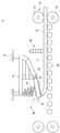
도 1은 본 발명의 일 실시예에 따른 소재 상향 제어 장치를 개략적으로 나타낸 도면이다.
도 2는 본 발명의 일 실시예에 따른 소재 상향 제어 장치의 접촉감지부를 나타낸 도면이다.
도 3은 선단부가 상향된 소재가 접촉감지부 설치지점을 통과하는 경우의 작동 상태를 나타낸 도면이다.
도 4는 도 3보다 상향량이 큰 소재가 접촉감지부 설치지점을 통과하는 경우의 작동 상태를 나타낸 도면이다.
도 5는 본 발명의 일 실시예에 따른 소재 상향 제어 장치의 회동프레임을 나타낸 저면도이다.
도 6은 본 발명의 일 실시예에 따른 소재 상향 제어 장치에서 소재가 상향교정부와 접촉하기 직전의 상태를 나타낸 도면이다.
도 7은 본 발명의 일 실시예에 따른 소재 상향 제어 장치에서 소재가 상향교정부와 접촉하는 상태를 나타낸 도면이다.
도 8은 본 발명의 일 실시예에 따른 소재 상향 제어 장치에서 소재가 상향교정부와 접촉한 직후의 상태를 나타낸 도면이다.
도 9는 본 발명의 일 실시예에 따른 소재 상향 제어 장치에서 상부워크롤을 통해 소재 선단부의 상향 변형을 교정하는 상태를 나타낸 도면이다.
도 10은 본 발명의 일 실시예에 따른 소재 상향 제어 장치에서 하부워크롤을 통해 소재 선단부의 상향 변형을 교정하는 상태를 나타낸 도면이다.
도 11은 본 발명의 일 실시예에 따른 소재 상향 제어 장치의 제어흐름을 나타낸 블록도이다.
도 12는 본 발명의 다른 실시예에 따른 소재 상향 제어 장치를 개략적으로 나타낸 도면이다.1 is a view schematically showing a material upward control device according to an embodiment of the present invention.
2 is a view showing a contact detection unit of the material upward control device according to an embodiment of the present invention.
3 is a view showing an operating state when the material whose tip is upwardly passes through the contact detecting unit installation point.
FIG. 4 is a view illustrating an operating state when a material having a larger upward amount than that of FIG. 3 passes through a contact detecting unit installation point.
Figure 5 is a bottom view showing a rotating frame of the material upward control device according to an embodiment of the present invention.
FIG. 6 is a view illustrating a state immediately before a material comes into contact with an upward corrector in a material upward control device according to an embodiment of the present invention.
7 is a view showing a state in which the material is in contact with the upward correction in the material upstream control device according to an embodiment of the present invention.
8 is a view showing a state immediately after the material is in contact with the upward correction in the material upward control device according to an embodiment of the present invention.
9 is a view showing a state of correcting the upward deformation of the material front end portion through the upper work roll in the material upward control device according to an embodiment of the present invention.
10 is a view showing a state of correcting the upward deformation of the material front end portion through the lower work roll in the material upward control device according to an embodiment of the present invention.
11 is a block diagram showing the control flow of the material upstream control apparatus according to an embodiment of the present invention.
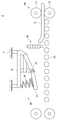
12 is a view schematically showing a material up-control device according to another embodiment of the present invention.
이하 첨부된 도면들을 참조하여 본 발명에 따른 소재 상향 제어 장치의 일 실시예를 설명한다. 이러한 과정에서 도면에 도시된 선들의 두께나 구성요소의 크기 등은 설명의 명료성과 편의상 과장되게 도시되어 있을 수 있다.Hereinafter, an embodiment of a material upward control device according to the present invention will be described with reference to the accompanying drawings. In this process, the thicknesses of the lines and the sizes of the components shown in the drawings may be exaggerated for clarity and convenience of explanation.
또한 후술되는 용어들은 본 발명에서의 기능을 고려하여 정의된 용어들로써 이는 사용자, 운용자의 의도 또는 관례에 따라 달라질 수 있다. 그러므로 이러한 용어들에 대한 정의는 본 명세서 전반에 걸친 내용을 토대로 내려져야 할 것이다.
Further, terms to be described below are defined in consideration of the functions of the present invention, which may vary according to the intention or custom of the user, the operator. Therefore, definitions of these terms should be made based on the contents throughout this specification.
도 1은 본 발명의 일 실시예에 따른 소재 상향 제어 장치를 개략적으로 나타낸 도면이고, 도 2는 본 발명의 일 실시예에 따른 소재 상향 제어 장치의 접촉감지부를 나타낸 도면이다. 도 3은 선단부가 상향된 소재가 접촉감지부 설치지점을 통과하는 경우의 작동 상태를 나타낸 도면이고, 도 4는 도 3보다 상향량이 큰 소재가 접촉감지부 설치지점을 통과하는 경우의 작동 상태를 나타낸 도면이며, 도 5는 본 발명의 일 실시예에 따른 소재 상향 제어 장치의 회동프레임을 나타낸 저면도이다. 도 6은 본 발명의 일 실시예에 따른 소재 상향 제어 장치에서 소재가 상향교정부와 접촉하기 직전의 상태를 나타낸 도면이고, 도 7은 본 발명의 일 실시예에 따른 소재 상향 제어 장치에서 소재가 상향교정부와 접촉하는 상태를 나타낸 도면이며, 도 8은 본 발명의 일 실시예에 따른 소재 상향 제어 장치에서 소재가 상향교정부와 접촉한 직후의 상태를 나타낸 도면이다. 도 9는 본 발명의 일 실시예에 따른 소재 상향 제어 장치에서 상부워크롤을 통해 소재 선단부의 상향 변형을 교정하는 상태를 나타낸 도면이고, 도 10은 본 발명의 일 실시예에 따른 소재 상향 제어 장치에서 하부워크롤을 통해 소재 선단부의 상향 변형을 교정하는 상태를 나타낸 도면이며, 도 11은 본 발명의 일 실시예에 따른 소재 상향 제어 장치의 제어흐름을 나타낸 블록도이다. 도 12는 본 발명의 다른 실시예에 따른 소재 상향 제어 장치를 개략적으로 나타낸 도면이다.
1 is a view schematically showing a material upward control device according to an embodiment of the present invention, Figure 2 is a view showing a touch sensing unit of the material upward control device according to an embodiment of the present invention. FIG. 3 is a view illustrating an operating state when the material whose tip is upwardly passes through the touch sensing unit installation point, and FIG. 4 is a view illustrating an operating state when the material having a larger upward amount passes through the touch sensing unit installing point than FIG. 3. 5 is a bottom view illustrating a rotation frame of a material upward control device according to an embodiment of the present invention. FIG. 6 is a view illustrating a state immediately before a material comes into contact with an upward corrector in a material upward control device according to an embodiment of the present invention, and FIG. 7 shows a material in the material upward control device according to an embodiment of the present invention. 8 is a view showing a state in contact with the up-correction, Figure 8 is a view showing a state immediately after the material is in contact with the up-correction in the material upstream control device according to an embodiment of the present invention. 9 is a view showing a state of correcting the upward deformation of the material front end portion through the upper work roll in the material upward control device according to an embodiment of the present invention, Figure 10 is a material upward control device according to an embodiment of the present invention Is a view showing a state of correcting the upward deformation of the material front end portion through the lower work roll, Figure 11 is a block diagram showing the control flow of the material upstream control apparatus according to an embodiment of the present invention. 12 is a view schematically showing a material up-control device according to another embodiment of the present invention.
도 1 내지 도 5, 도 11을 참조하면, 본 발명의 일 실시예에 따른 소재 상향 제어 장치(1)는 압연부(10), 이송롤러부(20), 상향교정부(30), 접촉감지부(40), 제어부(50), 디스플레이부(60)를 포함하여 이루어진다. 1 to 5, 11, the material
압연부(10)는 소재(S)가 사상압연 공정에서 마무리 압연이 용이하게 되도록 소재(S)를 목표하는 두께와 폭으로 압연한다. 압연부(10)는 상측에 배치되는 상부워크롤(11)과, 하측에 배치되는 하부워크롤(12)을 포함한다. The
소재(S)는 상부워크롤(11)과 하부워크롤(12) 사이로 이송되면서 상부워크롤(11)과 하부워크롤(12)에 의해 압연된다. 압연부(10)에서 압연되어 송출되는 소재(S)는 이송롤러부(20)에 의해 후공정으로 이송된다. The raw material S is rolled by the
이송롤러부(20)는 압연부(10)의 후방에 배치된다. 이송롤러부(20)는 소재(S)를 후공정으로 이송하는 이송롤러(부호 생략)와, 이송롤러의 양단부를 회전 가능하게 지지하는 롤러지지대(도시 생략)를 포함하여 이루어진다. The conveying
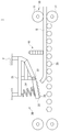
상향교정부(30)는 이송롤러부(20)의 상방에 배치된다. 압연부(10)에서 송출되는 소재(S)는 압연부(10)의 상하부워크롤(11, 12)의 속도차 등에 의해 상향이 발생될 수 있다. The
상향교정부(30)는 상향이 발생된 소재(S) 선단부에 충격을 가하여 소재(S) 선단부의 상향을 교정한다. 또한, 상향교정부(30)는 소재(S) 선단부와의 접촉 시 발생하는 충격을 흡수하여 상향교정부(30) 또는 소재(S) 선단부가 충격에 의해 파손되는 것을 억제한다. The
상향교정부(30)는 고정프레임(31), 회동프레임(32), 탄성부재(34), 롤러(35)를 포함한다. The
고정프레임(31)은 외부장치(F)에 고정된다. 외부장치(F)는 압연부(10)의 프레임을 이루는 압연프레임 또는 롤러테이블일 수 있으며, 그 외 고정프레임(31)을 이송롤러부(20)의 상방에 배치시킬 수 있는 구성이라면 그 어느 것이라도 무방하다. The
회동프레임(32)은 고정프레임(31)에 회전 가능하게 결합된다. 고정프레임(31)의 하단부(도 1 기준)는 힌지부(33)에 의해 회동프레임(32)의 우측단부와 힌지 결합된다. 이로써 회동프레임(32)은 고정프레임(31)에 대해 회전이 자유롭게 이루어진다.Rotating
롤러(35)는 회동프레임(32)에 회전 가능하게 설치된다. 롤러(35)의 하면은 회동프레임(32)의 하단보다 하측에 배치된다. 따라서 소재(S)의 선단부가 상향된 경우 소재(S)의 선단부는 회동프레임(32)에 접촉하기에 앞서 롤러(35)에 접촉된다. The
롤러(35)는 소재(S)의 이송 방향을 따라 회동프레임(32)에 복수개가 설치되므로 소재(S)의 선단부가 롤러(35)와 접촉되더라도 소재(S)의 이송속도가 저하되는 것을 방지할 수 있다. 따라서, 소재(S)의 이송 지연에 따른 작업 공정이 지연되는 것을 미연에 차단할 수 있다.Since a plurality of
롤러(35)는 소재(S)의 선단부가 상향된 경우 소재(S)의 선단부와 접촉할 수 있는 위치에 배치된다. 따라서 소재(S)의 선단부가 상향되지 않은 경우 소재(S)의 선단부와 롤러(35)는 접촉되지 않는다. The
반면, 소재(S)의 선단부가 상향된 경우에 소재(S)의 선단부는 롤러(35)와 접촉된다. 소재(S)의 선단부는 롤러(35)와의 접촉 시 발생하는 충격에 의해 상향 정도가 줄어든다. 즉, 소재(S)의 선단부는 상향교정부(30)에 의해 교정된 후 후공정으로 진입된다. On the other hand, when the front end of the work material S is raised, the front end of the work material S is in contact with the
탄성부재(34)는 소재(S)의 선단부와 롤러(35)의 접촉 시 발생하는 충격을 흡수한다. 탄성부재(34)는 일측이 고정프레임(31)에 고정되고, 타측이 회동프레임(32)에 고정되어 회동프레임(32)을 탄성 지지한다. The
소재(S)의 선단부와 롤러(35)가 접촉되는 경우, 회동프레임(32)은 힌지부(33)를 중심으로 시계 방향(도 1 기준)으로 회전된다. 이때 탄성부재(34)가 회동프레임(32)을 탄성 지지하고 있으므로 롤러(35)에 가해지는 충격은 탄성부재(34)에 의해 흡수된다. 이로써 접촉이 일어나는 두 대상, 즉 롤러(35)와 소재(S)의 선단부가 충격에 의해 파손되는 것을 방지할 수 있다. When the tip portion of the raw material S and the
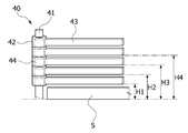
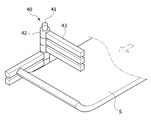
접촉감지부(40)는 소재(S) 선단부의 상향 시 소재(S) 선단부와 접촉되어 소재(S) 선단부의 상향을 감지한다. 이를 위해 접촉감지부(40)는 소재(S)의 이송 경로 상에 배치된다. The
접촉감지부(40)는 회동축(41), 회동부(42), 접촉바(43), 엔코더(44)를 포함하여 이루어진다. The
회동축(41)은 회동부(42)의 회전 중심축을 이루며, 접촉바(43)가 소재(S) 이송 경로 상에 수평 배치되도록 이송롤러 측방에 설치된다. 일 예로, 회동축(41)은 롤러지지대에 설치될 수 있다. The rotating
이외에도 회동축(41)은 이송롤러의 측방에 배치될 수 있다면, 다른 장치에 고정될 수 있음은 물론이다. 본 실시예에서, 회동축(41)은 원기둥 형상을 이루며, 상하 방향으로 연장 형성된다. In addition, the
회동부(42)는 회동축(41)에 회전 가능하게 결합된다. 회동부(42)는 소재(S) 이송 경로 상에 복수개 배치되는 접촉바(43)의 개수만큼 회동축(41)에 상하 방향으로 배치된다. The
접촉바(43)는 회동부(42)의 일측에 결합되어 소재(S)의 이송 경로 상에 수평 배치된다. 접촉바(43)는 소재(S)의 상향 여부뿐만 아니라 상향량을 정확히 측정할 수 있도록 복수개가 소재(S)의 이송 경로 상에서 상하 방향으로 수평 배치된다(도 2 참조). The
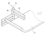
접촉바(43)는 소재(S)의 이송 경로 상에 배치되므로, 소재(S)의 선단부에 상향이 발생한 경우 소재(S)와 접촉하게 된다. 접촉바(43)가 소재(S)와 접촉하게 되면, 접촉바(43)와 연결되는 회동부(42)가 회동축(41)을 중심으로 회전하게 된다.Since the
이에 따라, 접촉바(43)는 소재(S)의 이송 경로 상에서 벗어나게 되면서, 소재(S) 이송의 장애물이 되지 않게 된다. 즉, 접촉바(43)는 소재(S) 선단부의 상향을 감지하기 위해 소재(S)의 이송 경로 상에 배치되는 것으로, 소재(S)와 접촉되면 소재(S)의 이송력에 쉽게 밀리도록 설계되어 소재(S)의 이송 속도를 저하시키지 않는다.Accordingly, the
또한, 접촉바(43)는 소재(S)에 비해 경도 등이 크게 낮은 재질로 형성되어, 소재(S)와의 접촉 시 소재(S)의 파손을 방지한다.In addition, the
회동부(42)에는 접촉바(43)의 회전을 감지하는 엔코더(44)가 내장된다. 엔코더(44)는 접촉바(43)의 회전이 감지되면 감지신호를 제어부(50)에 전송하여 소재(S) 선단부의 상향을 제어부(50)에 알린다.The
복수개의 회동부(42)에 있어서, 소재(S) 선단부와 접촉되는 접촉바(43)와 연결되는 회동부(42)만이 회동축(41)을 중심으로 회전된다. In the plurality of
도 3에서처럼, 소재(S) 선단부의 상향 정도가 아래 2개의 접촉바(43)의 높이에 대응되는 경우, 아래 2개의 접촉바(43)만이 소재(S) 선단부와 접촉되고, 이에 따라 아래 2개의 회동부(42)만이 회전된다. 이때, 회동부(42)에 내장되는 엔코더(44)는 감지신호를 제어부(50)에 전송하여 소재(S) 선단부의 상향이 발생하였음을 알린다. 이때, 상향량은 [H2 ~ H3의 값에서 소재(S) 두께만큼을 뺀 값]이다. As shown in FIG. 3, when the upward degree of the front end of the work material S corresponds to the height of the bottom two
마찬가지로, 도 4에서처럼, 소재(S) 선단부의 상향 정도가 아래 3개의 접촉바(43)의 높이에 대응되는 경우, 아래 3개의 접촉바(43)만이 소재(S) 선단부와 접촉되고, 이에 따라 아래 3개의 회동부(42)만이 회전된다. 이때, 회동부(42)에 내장되는 엔코더(44)는 감지신호를 제어부(50)에 전송하여 소재(S) 선단부의 상향이 발생하였음을 알린다. 이때, 상향량은 [H3 ~ H4의 값에서 소재(S) 두께만큼을 뺀 값]이다. Similarly, as shown in FIG. 4, when the upward degree of the front end of the work material S corresponds to the height of the bottom three
이와 같이, 접촉바(43)와 소재(S) 선단부의 접촉에 의한 회동부(42)의 회전을 통해서, 소재(S) 선단부에 상향이 있음을 알 수 있을 뿐만 아니라, 그 상향 정도를 알 수 있다.In this way, through the rotation of the
최하단의 접촉바(43)와 이송롤러의 간격은 H1이다. 따라서, 소재(S)의 상향량이 [H1에서 소재(S) 두께만큼을 뺀 값] 이하인 경우, 소재(S)는 접촉바(43)에 걸리지 않게 된다. 따라서, 압연 공정 상에서 수용할 수 있는 소재(S)의 상향 정도를 미리 파악하여 H1을 설정할 수 있다. 한편, 다양한 두께의 소재(S)에 대해 접촉감지부(40)를 활용할 수 있도록 H1 값의 조정을 위한 회동축(41)의 높이를 조절할 수 있음은 물론이다. The gap between the
디스플레이부(60)는 접촉감지부(40)와 연결되어 접촉감지부(40)에 의해 소재(S) 선단부의 상향 변형이 감지된 경우 이러한 정보를 화면에 출력한다. 출력되는 정보에는 상향 변형의 유무뿐만 아니라, 상향 변형의 정도를 나타내는 변형량도 출력될 수 있다. The
이와 같이, 디스플레이부(60)를 통해 출력되는 정보를 통해 작업자는 소재(S) 선단부의 상향 변형의 유무 및 정도를 파악할 수 있게 되며, 이를 토대로 압연부(10)의 구동을 제어하여 소재(S) 선단부의 변형을 교정할 수 있게 된다. 한편, 압연부(10)의 구동은 작업자가 수동으로 제어하는 것 외에 후술할 제어부(50)에 의해 자동으로 이루어질 수도 있다. In this way, the information output through the
디스플레이부(60)는 상향교정부(30)에 설치되어 작업자에게 소재(S) 선단부의 변형 정보를 안내한다. 또한, 작업자의 시야가 확보될 수 있는 곳이라면 상향교정부(30)가 아닌 다른 구성에도 디스플레이부(60)가 설치될 수 있음은 물론이다. The
제어부(50)는 접촉감지부(40)와 연결되어 접촉감지부(40)에 의해 파악된 소재(S) 선단부의 변형 정보를 토대로 압연부(10)의 구동을 제어한다.The
접촉감지부(40)를 통해 소재(S) 선단부의 상향 변형이 감지되면 제어부(50)는 접촉감지부(40)에서 전송되는 정보를 토대로 상부워크롤(11) 또는 하부워크롤(12)의 속도를 제어하여 소재(S) 선단부의 변형을 교정한다.
When an upward deformation of the front end portion of the material S is detected through the
이하 도 6 내지 도 8을 중심으로 본 발명의 일 실시예에 따른 소재 상향 제어 장치에서 상향교정부를 통해 소재의 상향이 교정되는 작동원리를 설명한다. Hereinafter, the operation principle of correcting the upward of the material through the upward correction in the material upward control device according to the embodiment of the present invention will be described with reference to FIGS. 6 to 8.
압연부(10)에서 송출되는 소재(S)는 이송롤러부(20)에 의해 후공정으로 이송된다. 이때 압연부(10)의 출구측에는 소재(S) 선단부의 상향을 교정하는 상향교정부(30)가 배치된다. The raw material S sent from the rolling
압연부(10)에서 송출되는 소재(S)는 상하부워크롤(11, 12)의 속도차 등에 의해 선단부에 상향이 발생할 수 있다. 소재(S) 선단부에 상향이 발생한 경우 소재(S) 선단부는 상향교정부(30)와 접촉되면서 상향 정도가 줄어든다.The raw material S sent from the rolled
소재(S)와의 접촉이 없는 경우 상향교정부(30)는 도 6과 같이 배치된다. 이후 선단부에 상향이 발생된 소재(S)가 상향교정부(30)가 배치된 지점을 통과하는 경우 상향교정부(30)는 소재(S)의 선단부와 접촉하게 된다(도 7). When there is no contact with the raw material S, the
소재(S)의 선단부는 롤러(35)와의 접촉 시 발생되는 충격에 의해 상향 정도가 줄어들게 된다. 이때 롤러(35)가 설치된 회동프레임(32)은 힌지부(33)를 중심으로 시계 방향으로 회전하면서, 그리고 탄성부재(34)에 의해 탄성 지지되면서 소재(S)와의 접촉 시 발생되는 충격을 흡수하게 된다. The tip portion of the material (S) is reduced in the upward degree by the impact generated when the contact with the
이후 상향 정도가 완화된 소재(S)는 상향교정부(30)를 통과하여 후공정으로 이송되고, 회동프레임(32)은 탄성부재(34)의 복원력에 의해 원위치로 복귀한다(도 8).
Then, the material S of which the upward degree is relaxed is passed through the upward
이하 도 9 내지 도 10을 중심으로 본 발명의 일 실시예에 따른 소재 상향 제어 장치에서 압연부의 제어에 의해 소재 선단부의 변형을 방지하는 방법에 대하여 설명한다. Hereinafter, a method of preventing deformation of the material tip part by controlling the rolling part in the material upward control device according to an embodiment of the present invention will be described with reference to FIGS. 9 to 10.
접촉감지부(40)는 소재(S)의 이송 경로 상에 배치되므로, 소재(S)가 압연부(10)로부터 언제 송출되는지를 파악할 필요가 없게 된다. 따라서, 소재(S)의 송출 시점을 파악하기 위해 필요한 각종 센서 등의 설치를 생략할 수 있어 비용을 절감할 수 있다.Since the
앞서 설명한 바와 같이, 접촉감지부(40)에서 소재(S)의 상향을 감지한 경우 이러한 정보를 디스플레이부(60)를 통해 출력한다. 제어부(50)는 전송된 정보를 토대로 하부워크롤(12) 대비 상부워크롤(11)의 속도를 증가시킨다(도 9). As described above, when the
한편, 도 10에서와 같이, 상부워크롤(11)의 속도가 정속으로 운행되는 경우에는 상부워크롤(11) 대비 하부워크롤(12)의 속도를 감소시킴으로써, 하부워크롤(12)이 상부워크롤(11)보다 느리게 회전되도록 한다.On the other hand, as shown in Figure 10, when the speed of the
이와 같이, 소재(S') 선단부에 상향이 발생하는 이유는 상부워크롤(11)에 비해 하부워크롤(12)의 속도가 빨라서 소재(S') 하부면에 연신이 많이 일어나기 때문이다. 따라서 압연부(10)에 새로이 진입하는 다음 소재(S)에 대한 압연 과정에서는 소재(S') 선단부의 상향 정도에 따라 상부워크롤(11)과 하부워크롤(12)의 속도를 차등 조절함으로써 소재(S) 선단부에 상향이 발생되는 것을 방지할 수 있다.
Thus, the reason why the upward direction occurs in the front end of the material (S ') is because the speed of the
도 12를 참조하면, 본 발명의 다른 실시예에 따른 소재 상향 제어 장치(2)는 압연부(10), 이송롤러부(20), 상향교정부(30), 접촉감지부(40), 제어부(50), 디스플레이부(60)를 포함하여 이루어진다. Referring to Figure 12, the material
다른 실시예에 따른 소재 상향 제어 장치는 일 실시예와는 롤러(35)의 유무에 있어 상이할 뿐 나머지 내용은 동일하므로, 일 실시예와 동일한 내용에 대해서는 구체적인 설명을 생략하기로 한다. The material upstream control device according to another embodiment is different from the one embodiment in the presence or absence of the
상향교정부(30)는 이송롤러부(20)의 상방에 배치된다. 본 실시예에 따른 상향교정부(30)는 상향이 발생된 소재(S) 선단부에 충격을 가하여 소재(S) 선단부의 상향을 교정한다. 또한, 상향교정부(30)는 소재(S) 선단부와의 접촉 시 발생하는 충격을 흡수하여 상향교정부(30) 또는 소재(S) 선단부가 충격에 의해 파손되는 것을 억제한다. The
상향교정부(30)는 고정프레임(31), 회동프레임(32), 탄성부재(34)를 포함한다. The
고정프레임(31)은 외부장치(F)에 고정된다. 회동프레임(32)은 고정프레임(31)에 회전 가능하게 결합된다. 고정프레임(31)의 하단부(도 12 기준)는 힌지부(33)에 의해 회동프레임(32)의 우측단부와 힌지 결합된다. 이로써 회동프레임(32)은 고정프레임(31)에 대해 회전이 자유롭게 이루어지며, 소재(S) 선단부와의 접촉 시 힌지부(33)를 중심으로 회전된다. The fixed
회동프레임(32)은 소재(S)의 선단부가 상향된 경우 소재(S)의 선단부와 접촉할 수 있는 위치에 배치된다. 따라서 소재(S)의 선단부가 상향되지 않은 경우 소재(S)의 선단부와 회동프레임(32)은 접촉되지 않는다. The
반면, 소재(S)의 선단부가 상향된 경우에는 소재(S)의 선단부는 회동프레임(32)과 접촉된다. 소재(S)의 선단부는 회동프레임(32)과의 접촉 시 발생하는 충격에 의해 상향 정도가 줄어든다. 이로써 소재(S)의 선단부는 상향교정부(30)에 의해 교정된 후 후공정으로 진입된다. On the other hand, when the front end of the work material S is upward, the front end of the work material S comes into contact with the
탄성부재(34)는 소재(S)의 선단부와 회동프레임(32)의 접촉 시 발생하는 충격을 흡수한다. 탄성부재(34)는 일측이 고정프레임(31)에 고정되고, 타측이 회동프레임(32)에 고정되어 회동프레임(32)을 탄성 지지한다. The
소재(S)의 선단부와 회동프레임(32)이 접촉되는 경우, 회동프레임(32)은 힌지부(33)를 중심으로 시계 방향으로 회전된다. 이때 탄성부재(34)가 회동프레임(32)을 탄성 지지하고 있으므로 회동프레임(32)에 가해지는 충격력은 탄성부재(34)에 의해 흡수된다. 이로써 접촉이 일어나는 두 대상, 즉 회동프레임(32)과 소재(S)의 선단부가 충격에 의해 파손되는 것을 방지할 수 있다. When the tip portion of the raw material S and the
접촉감지부(40) 역시 일 실시예와 마찬가지로, 회동축(41), 회동부(42), 접촉바(43), 엔코더(44)를 포함하여 이루어진다. 이러한 접촉감지부(40)를 통해 소재(S) 선단부의 상향 유무 및 정도를 정확하게 측정할 수 있게 된다.
Like one embodiment, the
본 발명은 도면에 도시되는 일 실시예를 참고로 하여 설명되었으나 이는 예시적인 것에 불과하며 당해 기술이 속하는 분야에서 통상의 지식을 가진 자라면 이로부터 다양한 변형 및 균등한 타 실시예가 가능하다는 점을 이해할 것이다. 따라서 본 발명의 진정한 기술적 보호범위는 아래의 특허청구범위에 의해서 정하여져야 할 것이다.
While the present invention has been particularly shown and described with reference to exemplary embodiments thereof, it is to be understood that the invention is not limited to the disclosed exemplary embodiments, but, on the contrary, is intended to cover various modifications and equivalent arrangements included within the spirit and scope of the appended claims. will be. Accordingly, the true scope of the present invention should be determined by the following claims.
1 : 소재 상향 제어 장치 10 : 압연부
20 : 이송롤러부 30 : 상향교정부
40 : 접촉감지부 41 : 회동축
42 : 회동부 43 : 접촉바
50 : 제어부 60 : 디스플레이부1: material upward control device 10: rolling part
20: feed roller unit 30: upward correction
40: contact detection unit 41: rotating shaft
42: rotating part 43: contact bar
50: control unit 60:
Claims (10)
상기 압연부의 후방에
배치되고, 상기 압연부에서 송출되는 상기 소재를 이송시키는 이송롤러부;
상기 이송롤러부의 상방에 배치되고, 상기 이송롤러부 상을 이동하는 상기 소재의 선단부와 접촉하여 상기 소재 선단부의 상향을 교정하며, 상기 소재 선단부와의 접촉 시 발생하는 충격을 흡수하는 상향교정부;
상기 소재의 이송 경로 상에 배치되고, 상기 소재 선단부의 상향 시 상기 소재 선단부와 접촉되어 상기 소재 선단부의 상향을 감지하는 접촉감지부; 및
상기 접촉감지부와 연결되어 상기 접촉감지부에서 감지된 상기 소재 선단부의 상향량에 따라 상기 압연부의 구동을 제어하는 제어부를 포함하는 것을 특징으로 하는 소재 상향 제어 장치.
A rolling unit for rolling a material;
Behind the rolling part
A conveying roller part disposed to convey the material sent from the rolling part;
An upward correction part disposed above the feed roller part to correct an upward direction of the material tip part by contacting the tip part of the material moving on the feed roller part, and absorbing an impact generated when contacting the material tip part;
A contact sensing unit disposed on the transport path of the raw material and contacting the raw material tip when the raw material tip is upward to detect the upward of the raw material tip; And
And a control unit connected to the contact detecting unit to control driving of the rolling unit according to an upward amount of the material leading end detected by the contact detecting unit.
상기 상향교정부는, 고정프레임;
상기 고정프레임과 힌지부에 의해 회전 가능하게 결합되고, 상기 소재의 선단부와 접촉되는 회동프레임; 및
일측이 상기 고정프레임에 고정되고, 타측이 상기 회동프레임에 고정되어 상기 회동프레임을 탄성 지지하는 탄성부재를 포함하는 것을 특징으로 하는 소재 상향 제어 장치.
The method of claim 1,
The upward correction portion, the fixed frame;
A rotatable frame rotatably coupled to the fixed frame and the hinge portion and in contact with the front end portion of the material; And
One side is fixed to the fixed frame, the other side is fixed to the rotating frame characterized in that it comprises an elastic member for elastically supporting the rotating frame.
상기 상향교정부는, 상기 회동프레임에 회전 가능하게 설치되는 롤러를 더 포함하고,
상기 롤러의 하단은 상기 회동프레임의 하면보다 하측에 배치되어 상기 소재 선단부의 상향 시 상기 소재 선단부와 상기 회동프레임의 접촉을 차단하는 것을 특징으로 하는 소재 상향 제어 장치.
The method of claim 2,
The upward corrector further includes a roller rotatably installed on the pivot frame,
The lower end of the roller is disposed below the lower surface of the rotation frame, the material upward control device, characterized in that to block the contact between the material front end and the rotation frame when the material front end.
상기 롤러는 상기 소재의 이송 방향을 따라 상기 회동프레임에 복수개가 설치되는 것을 특징으로 하는 소재 상향 제어 장치.
The method of claim 3,
The roller up material control device, characterized in that a plurality of rollers are installed in the rotation frame along the conveying direction of the material.
상기 접촉감지부와 연결되어 상기 접촉감지부에서 감지된 상기 소재 선단부의 상향량을 화면에 출력하는 디스플레이부를 더 포함하는 것을 특징으로 하는 소재 상향 제어 장치.
5. The method of claim 4,
And a display unit connected to the touch sensing unit and outputting an upward amount of the work leading end detected by the touch sensing unit to a screen.
상기 접촉감지부는, 회동축;
상기 회동축에 회전 가능하게 결합되는 회동부; 및
상기 회동부의 일측에 결합되고, 상기 소재의 이송 경로 상에 수평 배치되는 접촉바를 포함하고,
상기 회동부에는 상기 소재 선단부와의 접촉에 의한 상기 접촉바의 회전을 감지하는 엔코더가 내장되고, 상기 엔코더는 상기 접촉바의 회전이 감지되면 감지신호를 상기 제어부에 전송하는 것을 특징으로 하는 소재 상향 제어 장치.
The method of claim 1,
The contact detecting unit, the rotating shaft;
A rotating part rotatably coupled to the rotating shaft; And
A contact bar coupled to one side of the pivot part and disposed horizontally on a transport path of the material,
The rotating unit includes an encoder for detecting the rotation of the contact bar by the contact with the material tip, the encoder transmits a detection signal to the controller when the rotation of the contact bar is detected. controller.
상기 접촉바는 상기 소재 선단부의 상향량을 측정할 수 있도록 상기 소재의 이송 경로 상에 상하 방향으로 복수개가 수평 배치되고,
상기 접촉바의 개수에 대응되는 복수개의 상기 회동부가 상기 회동축에 상하 방향으로 배치되며,
상기 회동부는 상기 접촉바와 상기 소재 선단부와의 접촉 여부에 따라 상기 회동축을 중심으로 개별적으로 회전되는 것을 특징으로 하는 소재 상향 제어 장치.
The method according to claim 6,
The plurality of contact bars are horizontally arranged in the vertical direction on the transport path of the material so that the upward amount of the material tip portion can be measured,
A plurality of the rotating part corresponding to the number of the contact bar is disposed in the vertical direction on the rotating shaft,
And the pivot unit is individually rotated about the pivot shaft according to whether the contact bar is in contact with the material tip.
상기 압연부는, 상기 소재를 상부에서 가압하는 상부워크롤과, 상기 소재를 하부에서 가압하는 하부워크롤을 포함하고,
상기 제어부는, 상기 접촉감지부에서 감지된 상기 소재 선단부의 변형이 상향인 경우 상기 상부워크롤의 속도를 상기 하부워크롤의 속도보다 높게 하는 것을 특징으로 하는 소재 상향 제어 장치.
The method of claim 7, wherein
The rolling unit includes an upper work roll for pressing the material from the top, and a lower work roll for pressing the material from the bottom,
The control unit, the material upward control device, characterized in that for increasing the speed of the upper work roll than the speed of the lower work roll when the deformation of the material front end detected by the contact sensing unit is upward.
상기 압연부는, 상기 소재를 상부에서 가압하는 상부워크롤과, 상기 소재를 하부에서 가압하는 하부워크롤을 포함하고,
상기 제어부는 상기 접촉감지부에서 감지된 상기 소재 선단부의 변형이 상향인 경우 상기 하부워크롤의 속도를 상기 상부워크롤의 속도보다 낮게 하는 것을 특징으로 하는 소재 상향 제어 장치.
The method of claim 7, wherein
The rolling unit includes an upper work roll for pressing the material from the top, and a lower work roll for pressing the material from the bottom,
And the control unit lowers the speed of the lower work roll when the deformation of the material tip detected by the touch sensing unit is higher than the speed of the upper work roll.
상기 압연부의 후방에 배치되고, 상기 압연부에서 송출되는 상기 소재를 이송시키는 이송롤러부;
상기 이송롤러부의 상방에 배치되고, 상기 이송롤러부 상을 이동하는 상기 소재의 선단부와 접촉하여 상기 소재 선단부의 상향을 교정하며, 상기 소재 선단부와의 접촉 시 발생하는 충격을 흡수하는 상향교정부;
상기 소재의 이송 경로 상에 배치되고, 상기 소재 선단부의 상향 시 상기 소재 선단부와 접촉되어 상기 소재 선단부의 상향을 감지하는 접촉감지부; 및
상기 접촉감지부와 연결되어 상기 접촉감지부에서 감지된 상기 소재 선단부의 상향량을 화면에 출력하는 디스플레이부를 포함하는 것을 특징으로 하는 소재 상향 제어 장치. A rolling unit for rolling a material;
A conveying roller part disposed at the rear of the rolling part to convey the material sent from the rolling part;
An upward correction part disposed above the feed roller part to correct an upward direction of the material tip part by contacting the tip part of the material moving on the feed roller part, and absorbing an impact generated when contacting the material tip part;
A contact sensing unit disposed on the transport path of the raw material and contacting the raw material tip when the raw material tip is upward to detect the upward of the raw material tip; And
And a display unit connected to the touch sensing unit and outputting an upward amount of the top end portion detected by the touch sensing unit to a screen.
Priority Applications (1)
| Application Number | Priority Date | Filing Date | Title |
|---|---|---|---|
| KR1020110111044A KR101344331B1 (en) | 2011-10-28 | 2011-10-28 | Apparatus for controlling upward movement of material |
Applications Claiming Priority (1)
| Application Number | Priority Date | Filing Date | Title |
|---|---|---|---|
| KR1020110111044A KR101344331B1 (en) | 2011-10-28 | 2011-10-28 | Apparatus for controlling upward movement of material |
Publications (2)
| Publication Number | Publication Date |
|---|---|
| KR20130046576A true KR20130046576A (en) | 2013-05-08 |
| KR101344331B1 KR101344331B1 (en) | 2013-12-23 |
Family
ID=48658197
Family Applications (1)
| Application Number | Title | Priority Date | Filing Date |
|---|---|---|---|
| KR1020110111044A KR101344331B1 (en) | 2011-10-28 | 2011-10-28 | Apparatus for controlling upward movement of material |
Country Status (1)
| Country | Link |
|---|---|
| KR (1) | KR101344331B1 (en) |
Cited By (2)
| Publication number | Priority date | Publication date | Assignee | Title |
|---|---|---|---|---|
| KR101498896B1 (en) * | 2013-06-27 | 2015-03-05 | 현대제철 주식회사 | Leveler |
| CN105195526A (en) * | 2015-08-26 | 2015-12-30 | 山东钢铁股份有限公司 | Method and device for controlling head bending for plate strip rolling |
-
2011
- 2011-10-28 KR KR1020110111044A patent/KR101344331B1/en not_active IP Right Cessation
Cited By (3)
| Publication number | Priority date | Publication date | Assignee | Title |
|---|---|---|---|---|
| KR101498896B1 (en) * | 2013-06-27 | 2015-03-05 | 현대제철 주식회사 | Leveler |
| CN105195526A (en) * | 2015-08-26 | 2015-12-30 | 山东钢铁股份有限公司 | Method and device for controlling head bending for plate strip rolling |
| CN105195526B (en) * | 2015-08-26 | 2017-03-15 | 山东钢铁股份有限公司 | A kind of board rolling head-bent control method and device |
Also Published As
| Publication number | Publication date |
|---|---|
| KR101344331B1 (en) | 2013-12-23 |
Similar Documents
| Publication | Publication Date | Title |
|---|---|---|
| KR101344333B1 (en) | Apparatus for preventing upward movement of material | |
| KR101320126B1 (en) | Apparatus for preventing upward movement of strip | |
| KR101344331B1 (en) | Apparatus for controlling upward movement of material | |
| KR101424437B1 (en) | Moving apparatus for rolling mill and control method thereof | |
| KR101298709B1 (en) | Apparatus for preventing upward movement of material | |
| KR101344328B1 (en) | Apparatus for controlling upward movement of material | |
| KR20130002439A (en) | Apparatus for preventing upward movement of bar | |
| KR20090113062A (en) | An apparatus for guiding hot rolled steel sheet | |
| KR101344329B1 (en) | Apparatus for correcting upward movement of material | |
| KR101443102B1 (en) | Apparatus for adjusting curvature of material | |
| KR101498899B1 (en) | Apparatus for detecting slab | |
| KR20130034982A (en) | Apparatus for measuring shape of slab | |
| KR101237069B1 (en) | Transferring apparatus for fuel and raw material and control method thereof | |
| KR101344327B1 (en) | Apparatus for measuring shape of slab | |
| KR101225795B1 (en) | Apparatus for preventing upward movement of front part of strip | |
| KR101498896B1 (en) | Leveler | |
| KR20170021504A (en) | Feed roller unit | |
| KR101443095B1 (en) | Apparatus for correcting upward movement of material | |
| KR101225778B1 (en) | Apparatus for transferring material | |
| KR101435038B1 (en) | Rolling apparatus for material | |
| KR20130046572A (en) | Transferring apparatus for fuel and raw material | |
| KR101320147B1 (en) | Side guide automatic control apparatus for preventing strip serpentine movement | |
| KR101466164B1 (en) | Transferring apparatus for fuel and raw material | |
| KR101435030B1 (en) | Rolling control method of finishing mill | |
| KR100761740B1 (en) | Device for centering strip |
Legal Events
| Date | Code | Title | Description |
|---|---|---|---|
| A201 | Request for examination | ||
| E902 | Notification of reason for refusal | ||
| E701 | Decision to grant or registration of patent right | ||
| GRNT | Written decision to grant | ||
| LAPS | Lapse due to unpaid annual fee |