KR20130022390A - Apparatus and method for characterizing glass sheets - Google Patents
Apparatus and method for characterizing glass sheets Download PDFInfo
- Publication number
- KR20130022390A KR20130022390A KR1020120093215A KR20120093215A KR20130022390A KR 20130022390 A KR20130022390 A KR 20130022390A KR 1020120093215 A KR1020120093215 A KR 1020120093215A KR 20120093215 A KR20120093215 A KR 20120093215A KR 20130022390 A KR20130022390 A KR 20130022390A
- Authority
- KR
- South Korea
- Prior art keywords
- glass sheet
- air
- porous body
- air bearing
- body portion
- Prior art date
Links
- 239000011521 glass Substances 0.000 title claims abstract description 370
- 238000000034 method Methods 0.000 title claims abstract description 32
- 230000000087 stabilizing effect Effects 0.000 claims abstract description 41
- 238000011144 upstream manufacturing Methods 0.000 claims abstract description 16
- 238000012512 characterization method Methods 0.000 claims description 4
- 230000000116 mitigating effect Effects 0.000 claims description 4
- 238000004519 manufacturing process Methods 0.000 abstract description 17
- 230000004927 fusion Effects 0.000 abstract description 7
- 239000003570 air Substances 0.000 description 331
- 230000006641 stabilisation Effects 0.000 description 59
- 238000011105 stabilization Methods 0.000 description 59
- 239000000463 material Substances 0.000 description 31
- 238000005259 measurement Methods 0.000 description 25
- 230000007246 mechanism Effects 0.000 description 14
- 239000006060 molten glass Substances 0.000 description 14
- 230000008569 process Effects 0.000 description 12
- 238000003756 stirring Methods 0.000 description 11
- 239000012530 fluid Substances 0.000 description 9
- 238000005452 bending Methods 0.000 description 8
- 238000004891 communication Methods 0.000 description 7
- 239000000758 substrate Substances 0.000 description 7
- 238000012545 processing Methods 0.000 description 6
- 238000007667 floating Methods 0.000 description 5
- 238000012360 testing method Methods 0.000 description 5
- 238000012876 topography Methods 0.000 description 5
- 230000000694 effects Effects 0.000 description 4
- 238000007689 inspection Methods 0.000 description 4
- 238000000465 moulding Methods 0.000 description 4
- 230000003287 optical effect Effects 0.000 description 4
- BASFCYQUMIYNBI-UHFFFAOYSA-N platinum Chemical compound [Pt] BASFCYQUMIYNBI-UHFFFAOYSA-N 0.000 description 4
- 230000008901 benefit Effects 0.000 description 3
- 238000004090 dissolution Methods 0.000 description 3
- 230000000737 periodic effect Effects 0.000 description 3
- 238000012546 transfer Methods 0.000 description 3
- OKTJSMMVPCPJKN-UHFFFAOYSA-N Carbon Chemical group [C] OKTJSMMVPCPJKN-UHFFFAOYSA-N 0.000 description 2
- XEEYBQQBJWHFJM-UHFFFAOYSA-N Iron Chemical compound [Fe] XEEYBQQBJWHFJM-UHFFFAOYSA-N 0.000 description 2
- 229910000629 Rh alloy Inorganic materials 0.000 description 2
- MCMNRKCIXSYSNV-UHFFFAOYSA-N Zirconium dioxide Chemical compound O=[Zr]=O MCMNRKCIXSYSNV-UHFFFAOYSA-N 0.000 description 2
- 238000004887 air purification Methods 0.000 description 2
- 238000013459 approach Methods 0.000 description 2
- 239000000919 ceramic Substances 0.000 description 2
- 239000013078 crystal Substances 0.000 description 2
- 238000005520 cutting process Methods 0.000 description 2
- 230000001419 dependent effect Effects 0.000 description 2
- 238000013461 design Methods 0.000 description 2
- 238000003280 down draw process Methods 0.000 description 2
- 229940082150 encore Drugs 0.000 description 2
- 238000005188 flotation Methods 0.000 description 2
- 239000010439 graphite Substances 0.000 description 2
- 229910002804 graphite Inorganic materials 0.000 description 2
- 239000007788 liquid Substances 0.000 description 2
- 239000004973 liquid crystal related substance Substances 0.000 description 2
- 238000002844 melting Methods 0.000 description 2
- 230000008018 melting Effects 0.000 description 2
- 229910052751 metal Inorganic materials 0.000 description 2
- 239000002184 metal Substances 0.000 description 2
- 238000012986 modification Methods 0.000 description 2
- 230000004048 modification Effects 0.000 description 2
- 230000002688 persistence Effects 0.000 description 2
- 229910052697 platinum Inorganic materials 0.000 description 2
- PXXKQOPKNFECSZ-UHFFFAOYSA-N platinum rhodium Chemical compound [Rh].[Pt] PXXKQOPKNFECSZ-UHFFFAOYSA-N 0.000 description 2
- 239000011148 porous material Substances 0.000 description 2
- 235000012431 wafers Nutrition 0.000 description 2
- 229910001260 Pt alloy Inorganic materials 0.000 description 1
- XUIMIQQOPSSXEZ-UHFFFAOYSA-N Silicon Chemical compound [Si] XUIMIQQOPSSXEZ-UHFFFAOYSA-N 0.000 description 1
- 230000009471 action Effects 0.000 description 1
- PNEYBMLMFCGWSK-UHFFFAOYSA-N aluminium oxide Inorganic materials [O-2].[O-2].[O-2].[Al+3].[Al+3] PNEYBMLMFCGWSK-UHFFFAOYSA-N 0.000 description 1
- 239000012080 ambient air Substances 0.000 description 1
- 230000003466 anti-cipated effect Effects 0.000 description 1
- 239000011449 brick Substances 0.000 description 1
- 229910010293 ceramic material Inorganic materials 0.000 description 1
- 230000008859 change Effects 0.000 description 1
- 230000000295 complement effect Effects 0.000 description 1
- 239000002131 composite material Substances 0.000 description 1
- 238000010924 continuous production Methods 0.000 description 1
- 230000007423 decrease Effects 0.000 description 1
- 230000007547 defect Effects 0.000 description 1
- 230000008030 elimination Effects 0.000 description 1
- 238000003379 elimination reaction Methods 0.000 description 1
- 238000011156 evaluation Methods 0.000 description 1
- 239000005357 flat glass Substances 0.000 description 1
- 230000009477 glass transition Effects 0.000 description 1
- 239000010438 granite Substances 0.000 description 1
- 238000010438 heat treatment Methods 0.000 description 1
- 238000009434 installation Methods 0.000 description 1
- 229910052742 iron Inorganic materials 0.000 description 1
- 238000000691 measurement method Methods 0.000 description 1
- 238000002156 mixing Methods 0.000 description 1
- 239000000203 mixture Substances 0.000 description 1
- 230000008447 perception Effects 0.000 description 1
- 239000000843 powder Substances 0.000 description 1
- 238000004886 process control Methods 0.000 description 1
- 230000000750 progressive effect Effects 0.000 description 1
- 238000000746 purification Methods 0.000 description 1
- 230000009467 reduction Effects 0.000 description 1
- 238000006748 scratching Methods 0.000 description 1
- 230000002393 scratching effect Effects 0.000 description 1
- 238000007493 shaping process Methods 0.000 description 1
- 229910052710 silicon Inorganic materials 0.000 description 1
- 239000010703 silicon Substances 0.000 description 1
- 238000003283 slot draw process Methods 0.000 description 1
- 239000007787 solid Substances 0.000 description 1
- 239000000126 substance Substances 0.000 description 1
- 238000009827 uniform distribution Methods 0.000 description 1
- 238000012800 visualization Methods 0.000 description 1
- XLYOFNOQVPJJNP-UHFFFAOYSA-N water Substances O XLYOFNOQVPJJNP-UHFFFAOYSA-N 0.000 description 1
Images


Classifications
-
- G—PHYSICS
- G01—MEASURING; TESTING
- G01N—INVESTIGATING OR ANALYSING MATERIALS BY DETERMINING THEIR CHEMICAL OR PHYSICAL PROPERTIES
- G01N33/00—Investigating or analysing materials by specific methods not covered by groups G01N1/00 - G01N31/00
- G01N33/38—Concrete; Lime; Mortar; Gypsum; Bricks; Ceramics; Glass
-
- B—PERFORMING OPERATIONS; TRANSPORTING
- B65—CONVEYING; PACKING; STORING; HANDLING THIN OR FILAMENTARY MATERIAL
- B65G—TRANSPORT OR STORAGE DEVICES, e.g. CONVEYORS FOR LOADING OR TIPPING, SHOP CONVEYOR SYSTEMS OR PNEUMATIC TUBE CONVEYORS
- B65G51/00—Conveying articles through pipes or tubes by fluid flow or pressure; Conveying articles over a flat surface, e.g. the base of a trough, by jets located in the surface
- B65G51/02—Directly conveying the articles, e.g. slips, sheets, stockings, containers or workpieces, by flowing gases
- B65G51/03—Directly conveying the articles, e.g. slips, sheets, stockings, containers or workpieces, by flowing gases over a flat surface or in troughs
-
- G—PHYSICS
- G01—MEASURING; TESTING
- G01N—INVESTIGATING OR ANALYSING MATERIALS BY DETERMINING THEIR CHEMICAL OR PHYSICAL PROPERTIES
- G01N33/00—Investigating or analysing materials by specific methods not covered by groups G01N1/00 - G01N31/00
- G01N33/38—Concrete; Lime; Mortar; Gypsum; Bricks; Ceramics; Glass
- G01N33/386—Glass
-
- C—CHEMISTRY; METALLURGY
- C03—GLASS; MINERAL OR SLAG WOOL
- C03B—MANUFACTURE, SHAPING, OR SUPPLEMENTARY PROCESSES
- C03B17/00—Forming molten glass by flowing-out, pushing-out, extruding or drawing downwardly or laterally from forming slits or by overflowing over lips
-
- C—CHEMISTRY; METALLURGY
- C03—GLASS; MINERAL OR SLAG WOOL
- C03B—MANUFACTURE, SHAPING, OR SUPPLEMENTARY PROCESSES
- C03B35/00—Transporting of glass products during their manufacture, e.g. hot glass lenses, prisms
- C03B35/14—Transporting hot glass sheets or ribbons, e.g. by heat-resistant conveyor belts or bands
- C03B35/20—Transporting hot glass sheets or ribbons, e.g. by heat-resistant conveyor belts or bands by gripping tongs or supporting frames
Landscapes
- Chemical & Material Sciences (AREA)
- Engineering & Computer Science (AREA)
- Health & Medical Sciences (AREA)
- Life Sciences & Earth Sciences (AREA)
- Physics & Mathematics (AREA)
- Analytical Chemistry (AREA)
- General Health & Medical Sciences (AREA)
- Food Science & Technology (AREA)
- Medicinal Chemistry (AREA)
- Organic Chemistry (AREA)
- Materials Engineering (AREA)
- Biochemistry (AREA)
- Ceramic Engineering (AREA)
- General Physics & Mathematics (AREA)
- Immunology (AREA)
- Pathology (AREA)
- Fluid Mechanics (AREA)
- Mechanical Engineering (AREA)
- Re-Forming, After-Treatment, Cutting And Transporting Of Glass Products (AREA)
- Container, Conveyance, Adherence, Positioning, Of Wafer (AREA)
- Delivering By Means Of Belts And Rollers (AREA)
Abstract
Description
본 출원은 2011년 8월 24일에 출원된 미국 가출원 번호 제61/526860호의 35 U.S.C. §119 아래 우선권의 이점을 청구하며 그 내용은 전체 문서에서 참조로써 의지되고 병합된다. This application claims 35 U.S.C. of US Provisional Application No. 61/526860, filed August 24, 2011. §119 Claims the benefits of priority underneath, which are incorporated and incorporated by reference throughout the document.
본 발명은 유리시트를 특성화하는 장치 및 방법에 관한 것이며, 특히 유리시트가 작동 중에 유리시트의 하나 또는 그 이상의 선택된 속성을 측정하도록 채택된 장치에 관한 것이다.FIELD OF THE INVENTION The present invention relates to apparatus and methods for characterizing glass sheets, and in particular, to apparatus wherein the glass sheet is adapted to measure one or more selected attributes of the glass sheet during operation.
본 발명은 토포그래피(topography) 검사(예를 들어 나노토포그래피 또는 나노미터 규모에서의 토포그래피)와 같이 고해상도 온라인 측정을 가능하게 하는 예정된 경로를 따라 이송되는 유리시트의 움직임과 속성을 제어하는 것에 관한 것이다. 박막 유리시트의 정확한 온라인 측정, 및 특히 나노미터 규모 특성의 측정은 예정된 방향에서 예정된 평면의 유리시트를 지속적으로 나타내는 것과 유리의 대부분의 진동과 움직임을 제거하는 것에 따라 매우 달라진다. 두께, 굴곡 및 코드의 고정밀 측정과 같은 시험은 재생가능한, 높은 공차 재료 처리를 가지는 측정 게이지에 대해 유리표면을 나타내는 것에 따라 매우 달라진다.The present invention is directed to controlling the motion and properties of glass sheets being transported along predetermined paths that enable high resolution online measurements, such as topography inspections (e.g., topography on a nanotopography or nanometer scale). It is about. Accurate on-line measurement of thin glass sheets, and especially measurement of nanometer scale properties, is very dependent on the continuous display of the predetermined flat glass sheet in the predetermined direction and the elimination of most vibrations and movements of the glass. Tests such as high precision measurements of thickness, flexure and cord are highly dependent on showing the glass surface for a measurement gauge with a reproducible, high tolerance material treatment.
온라인 코드와 스트리크(streak) 검사와 같은 온라인 공정 조절과 수준높은 측정은 높은 수준이 아닌 영역에서 유리를 간단히 쥐는 동안 수행될 때 반복성의 결함을 겪는다. 재료 제시 시험의 큰 부분은 오버헤드 컨베이어(conveyor)의 캐리어(carrier)로부터 매달린 동안 제조라인 아래로 이동하는 유리시트를 유지시키는 것이다. 이 제한은 종종 힘 측정이 완전히 오프라인인 공정라인의 개별적인 검사부분 중 하나에서 수행되도록 하거나, 또는 광범위한 종래 온라인 재료 처리와 호환가능한 측정 기술은 그 수행력(예를 들어, 해상도)에 제한된다.On-line process control and high-level measurements, such as on-line code and streak inspection, suffer from repeatability defects when performed while simply grasping glass in non-high-level areas. A large part of the material presentation test is to keep the glass sheet moving down the manufacturing line while suspended from the carrier of the overhead conveyor. This limitation often allows force measurements to be performed in one of the individual inspection portions of the process line that are completely offline, or measurement techniques compatible with a wide range of conventional on-line material processing are limited in their performance (eg, resolution).
고해상도 도량형(metrology)은 실리콘 웨이퍼 또는 종이 및 플라스틱 웨브와 같은 다른 산업들에서 온라인으로 수행되나, 이러한 경우, 제품은 웨이퍼들 또는 롤러들 또는 대부분의 웨브로써 지지판에 직접 접촉한다. 디스플레이 적용에 적합한 유리시트의 크기와 접촉 금지는 처리에 대한 어려운 시험을 나타낸다.High resolution metrology is performed online in other industries such as silicon wafers or paper and plastic webs, but in this case the product is in direct contact with the support plate with wafers or rollers or most webs. The size of glass sheets and contact prohibitions suitable for display applications represent a difficult test for processing.
일반적으로 두께가 1mm 또는 그 이하인 박막 유리시트의 측정은 특히 유리가 크다면(예를 들어 약 4m2) 유리의 특성 속성을 측정할 때, 어려움을 발생시키는 곡률 또는 뒤틀림의 양을 나타낼 수 있다. 이러한 단점을 극복하기 위하여, 유리는 우선 평탄해야 한다. 과거에, 유리시트를 평탄하게 하고 안정화하는 것은 내측라인 경로로부터 시트를 제거하고, 유리시트를 화강암 베이스로 전달시킨 후, 진공테이블로 개별적인 유리시트를 진공시키며, 원하는 치수를 만들고, 유리시트를 제거한 후 또다른 유리시트로 같은 작동을 수행하는 단계를 포함했다. 그러한 단편적인 접근은 제조공정에 상당한 시간과 비용이 추가된다. 큰 박막 유리시트를 측정하는 시험은 유리시트가 제조라인을 따라 이송되는 동안 유리시트를 측정할 필요가 있다면 악화된다.In general, the measurement of thin glass sheets having a thickness of 1 mm or less may indicate the amount of curvature or distortion that causes difficulties, especially when measuring the glass's characteristic properties, especially if the glass is large (eg, about 4 m 2 ). In order to overcome this disadvantage, the glass must first be flat. In the past, flattening and stabilizing the glass sheet removed the sheet from the inner line path, transferred the glass sheet to the granite base, vacuumed the individual glass sheets with a vacuum table, made the desired dimensions, and removed the glass sheets. And then performing the same operation with another glass sheet. Such a fragmentary approach adds significant time and cost to the manufacturing process. The test of measuring large thin glass sheets deteriorates if it is necessary to measure the glass sheets while they are transported along the manufacturing line.
몇몇 제조공정에서, 유리시트는 오버헤드 컨베이어에서 이송부재로 유리시트를 클램핑함으로써 한 위치에서 다른 위치로 이송될 수 있다. 먼저 유리시트의 분리와 정지 물체로써 측정 테이블에 유리시트를 위치시키는 것 없이 유리시트가 움직이는 동안 하나 또는 그 이상의 상기 언급된 특성이 수행된다면 이롭다.In some manufacturing processes, the glass sheet can be transferred from one position to another by clamping the glass sheet from the overhead conveyor to the conveying member. It is advantageous if one or more of the above mentioned properties are carried out while the glass sheet is moving without first separating the glass sheet and placing the glass sheet on the measurement table as a stationary object.
이를 달성하기 위하여, 장치는 이송 캐리어에 의해 여전히 고정되는 동안 유리시트를 제한함으로써, 액정 크리스탈 디스플레이 장치에 사용되기 적합한 유리시트와 같이 이동 유리시트의 정밀한 측정을 수행하기 위해 공개된다. 장치의 재료 처리 특성은 에어 나이프들과 압력-진공(PV) 에어 베어링을 포함하며, 장치로 들어가는 유리시트는 접촉되지 않으나 측정이 수행될 수 있는 지점까지 제한힘이 점진적으로 증가하도록 선형방식으로 배치된다. 제한힘의 점진적인 감소는 그후 시트가 장치로부터 분리될 때까지 발생한다. 이 누진 힘 기술은 유리시트의 진행방향을 따라 적용되며 또한 이송 캐리어 근처의 핀치점에서의 제한 없이 시트의 움직임을 제한하기 위해 시트의 높이를 따라 수직으로 위로 향한다.To achieve this, the device is disclosed for performing precise measurements of moving glass sheets, such as glass sheets suitable for use in liquid crystal crystal display devices, by limiting the glass sheets while still being fixed by the transport carrier. The material handling characteristics of the device include air knives and pressure-vacuum (PV) air bearings, and the glass sheets entering the device are not in contact but arranged in a linear fashion so that the limiting force gradually increases to the point where measurements can be made. do. The gradual reduction of the limiting force then occurs until the sheet is separated from the device. This progressive force technique is applied along the advancing direction of the glass sheet and is also directed vertically upward along the height of the sheet to limit the movement of the sheet without restriction at the pinch point near the conveying carrier.
따라서, 에어 베어링은 내측 다공성 본체부의 표면의 원형 홈부를 구비하는 환형의 내측 다공성 본체부를 구비하도록 공개되며, 다수의 방사형 홈부는 환형의 홈부를 교차하며, 내측 다공성 본체부는 에어 베어링의 두께를 통해 뻗어있는 중앙 통로를 형성하며; 외측 다공성 본체는 내측 다공성 본체에 배치되며, 외측 다공성 본체는 외측 다공성 본체의 표면의 다수의 연속적인 홈부들을 구비하며; 외측 다공성 본체의 각각의 연속적인 홈부는 다수의 진공 포트를 구비한다. 내측 다공성의 본체부의 원형 홈부와 내측 다공성의 본체부의 방사형 홈부는 내측 다공성의 본체부의 표면을 다수의 서브-표면으로 나누고, 다수의 서브-표면의 서브표면은 진공 포트를 구비한다. 바람직하게, 다수의 서브-표면의 각각의 서브표면은 진공 포트를 구비한다.Thus, the air bearing is disclosed to have an annular inner porous body portion having a circular groove portion on the surface of the inner porous body portion, wherein a plurality of radial groove portions cross the annular groove portion, and the inner porous body portion extends through the thickness of the air bearing. Form a central passageway; The outer porous body is disposed in the inner porous body, the outer porous body having a plurality of continuous grooves on the surface of the outer porous body; Each successive groove of the outer porous body has a plurality of vacuum ports. The circular groove portion of the inner porous body portion and the radial groove portion of the inner porous body portion divide the surface of the inner porous body portion into a plurality of sub-surfaces, and the sub surface of the plurality of sub-surfaces has a vacuum port. Preferably, each subsurface of the plurality of sub-surfaces has a vacuum port.
외측 다공성 본체부는 바람직하게 아치형의 외주를 구비하며, 바람직하게 외측 다공성 본체부는 원형의 외주를 구비하여 에어 베어링은 환형의 내측 다공성 본체부와 내측 다공성 본체부 및 동심으로 위치된 환형의 내측 다공성 본체부를 구비한다. 몇몇 실시예에서 에어 베어링은 다수의 내측 다공성 본체부를 구비한다. 예를 들어, 다수의 내측 다공성 본체부는 수평축을 따라 정렬될 수 있다.The outer porous body portion preferably has an arcuate outer circumference, preferably the outer porous body portion has a circular outer circumference such that the air bearing has an annular inner porous body portion and an inner porous body portion and a concentrically positioned annular inner porous body portion. Equipped. In some embodiments the air bearing has a plurality of inner porous body portions. For example, the plurality of inner porous body portions can be aligned along the horizontal axis.
몇몇 실시예에서, 유리시트가 장치를 지날 때 유리시트 특성화 장치는 환형의 내측 다공성 본체부, 및 상기 내측 다공성 본체부에 배치된 외측 다공성 본체부를 구비하는 에어 베어링; 및 유리시트의 진행방향과 관련하여 에어 베어링의 업스트림(upstream)에 위치된 다수의 에어 안정화 나이프들(stabilizing air knives); 및 상기 유리시트의 적어도 하나의 속성을 측정하기 위한 측정장치를 구비하며, 상기 내측 다공성 본체부는 상기 에어 베어링의 두께를 통해 뻗어있는 중앙 통로를 형성하며, 상기 측정장치는 상기 에어 베어링의 중앙 통로에 정렬된다. 내측 다공성 본체부는 그 표면의 원형 홈부를 구비한다. 내측 다공성 본체부는 게다가 원형 홈부와 교차하는 다수의 원형 홈부를 구비한다. 내측 다공성 본체부의 표면은 진공 포트를 구비한다. 내측 다공성의 본체부가 원형 홈부와 다수의 방사형 홈부를 구비한다면, 원형 홈부와 방사형 내측 홈부는 내측 다공성 본체부에 다수의 서브-표면을 형성한다. 바람직하게, 각각의 서브-표면은 진공 포트를 구비한다.In some embodiments, the glass sheet characterizing device as the glass sheet passes through the device comprises an air bearing having an annular inner porous body portion and an outer porous body portion disposed on the inner porous body portion; And a plurality of stabilizing air knives located upstream of the air bearing in relation to the direction of travel of the glass sheet; And a measuring device for measuring at least one property of the glass sheet, wherein the inner porous body forms a central passage extending through the thickness of the air bearing, and the measuring device is connected to the central passage of the air bearing. Aligned. The inner porous body has a circular groove on its surface. The inner porous body portion further has a plurality of circular groove portions that intersect the circular groove portions. The surface of the inner porous body portion has a vacuum port. If the inner porous body portion has a circular groove portion and a plurality of radial groove portions, the circular groove portion and the radial inner groove portion form a plurality of sub-surfaces on the inner porous body portion. Preferably, each sub-surface has a vacuum port.
외측 다공성 본체부는 다수의 연속적인(즉, 폐쇄된) 홈부를 구비하고, 각각의 연속적인 홈부는 다수의 진공 포트를 구비한다. 예를 들어, 각각의 연속적인 홈부는 환형, 계란형, 타원형 또는 임의의 다른 폐쇄된 연속적인 형상일 수 있다. 바람직하게, 외측 다공성 본체부의 외주는 아치형이다. 예를 들어, 외측 다공성 본체부의 외주는 원형이다. 에어 베어링은 몇몇 실시예에서 다수의 내측 다공성 본체부를 포함한다.The outer porous body has a plurality of continuous (ie closed) grooves, each continuous groove having a plurality of vacuum ports. For example, each continuous groove may be annular, oval, elliptical or any other closed continuous shape. Preferably, the outer circumference of the outer porous body portion is arcuate. For example, the outer circumference of the outer porous body portion is circular. The air bearing includes in some embodiments a plurality of inner porous body portions.
측정 장치는 바람직하게 내측 다공성 본체부에 의해 형성된 통로를 통해 적어도 하나의 속성을 측정한다.The measuring device preferably measures at least one property through the passage formed by the inner porous body.
에어 안정화 나이프들은 에어 안정화 나이프들로부터 에어의 흐름이 아래 방향으로 기울어지도록 향한다. 즉, 에어 안정화 나이프들로부터의 에어 흐름은 바람직하게 수평면에 대하여 아래 방향을 향하여 에어 흐름은 유리시트와 정확한 각도를 이룬다. 예를 들어, 에어 흐름의 방향은 유리시트와 관련하여 약 15도에서 약 75도의 범위의 각도를 형성할 수 있다. 바람직하게, 에어 안정화 나이프들은 아치형상이다.The air stabilization knives are directed such that the flow of air from the air stabilization knives is tilted downward. That is, the air flow from the air stabilizing knives is preferably directed downward with respect to the horizontal plane and the air flow is at an exact angle with the glass sheet. For example, the direction of air flow can form an angle in the range of about 15 degrees to about 75 degrees with respect to the glass sheet. Preferably, the air stabilizing knives are arcuate.
본 실시예에 따른 장치는 유리시트를 에어 베어링으로부터 먼 방향으로 가하도록 에어 베어링의 다운스트림(downstream)에 위치된 에어 배치 나이프를 더 구비할 수 있다.The apparatus according to this embodiment may further comprise an air positioning knife located downstream of the air bearing to apply the glass sheet in a direction away from the air bearing.
여전히 다른 실시예에서, 이동 유리시트 특성화 방법은 예정된 경로를 따라 제1 방향으로 유리시트를 이동시키는 단계; 유리시트가 상기 제1 방향으로 움직일 때 적어도 두 개의 에어 안정화 나이프들 사이의 유리시트를 지나게 함으로써 제1 방향과 직교인 제2 방향의 유리시트 움직임을 완화하는 단계; 상기 유리시트를 원형의 에어 베어링에 연결시키는 단계; 상기 유리시트를 상기 제1 방향으로 움직일 때 상기 유리시트의 적어도 하나의 속성을 측정하는 단계를 포함하고, 상기 유리시트는 한 쌍의 마주보는 주요면들, 밑면 에지 및 상기 제1 방향과 관련된 선단 에지를 구비하며, 상기 원형의 에어 베어링은 내측 다공성 본체부와 상기 내측 다공성 본체부에 위치된 외측 다공성 본체부를 구비하며, 상기 내측 다공성 본체부는 관통하는 중앙 통로를 형성한다. 본 방법은 안내 암 사이의 "V" 형상의 슬롯을 형성하기 위해 배치된 안내 암을 구비하는 에지 안내장치를 가진 유리시트의 밑면 에지를 안내하는 단계를 더 포함한다.In yet another embodiment, the moving glass sheet characterization method includes moving the glass sheet in a first direction along a predetermined path; Mitigating glass sheet movement in a second direction orthogonal to the first direction by passing the glass sheet between at least two air stabilizing knives when the glass sheet moves in the first direction; Connecting the glass sheet to a circular air bearing; Measuring at least one property of the glass sheet when the glass sheet is moved in the first direction, the glass sheet having a pair of opposing major surfaces, a bottom edge, and a tip associated with the first direction An edge, wherein the circular air bearing has an inner porous body portion and an outer porous body portion located in the inner porous body portion, the inner porous body portion forming a central passage therethrough. The method further includes guiding the bottom edge of the glass sheet with the edge guide device having a guide arm disposed to form a “V” shaped slot between the guide arms.
에어 베어링 높이, 및 더 특히 외측 다공성 본체부의 높이는 유리시트 높이의 1/2 이하이다. 에어 베어링은 유리시트가 측정될 때 유리시트의 상부 절반이 바람직하게 에어 베어링에 인접하지 않도록 배치된다. 에어 베어링은 바람직하게 내측 다공성 본체로부터 예정된 거리의 +/-15㎛ 내의 유리시트를 유지할 수 있다.The air bearing height, and more particularly the height of the outer porous body portion, is less than half the height of the glass sheet. The air bearing is arranged such that the upper half of the glass sheet is preferably not adjacent to the air bearing when the glass sheet is measured. The air bearing may preferably hold the glass sheet within +/- 15 μm of the predetermined distance from the inner porous body.
제1 내측 다공성 본체부는 그 표면에 원형 홈부를 구비한다. 내측 다공성 본체부는 바람직하게 내측 다공성 본체부의 표면의 다수의 방사형 홈부를 또한 구비하며, 다수의 방사형 홈부는 원형 홈부를 교차한다.The first inner porous body portion has a circular groove portion on its surface. The inner porous body portion preferably also has a plurality of radial groove portions on the surface of the inner porous body portion, the plurality of radial groove portions intersecting the circular groove portions.
에어 베어링의 내측 다공성 본체부는 바람직하게 다수의 중앙 홈부를 구비하며, 다수의 중앙 홈부의 각각의 홈부는 다수의 진공 포트를 구비한다. The inner porous body of the air bearing preferably has a plurality of central grooves, and each groove of the plurality of central grooves has a plurality of vacuum ports.
여전히 또다른 실시예에서, 유리시트 제조방법은: 용융유리 재료를 형성하기 위해 용융소에 배취(batch) 재료를 가열하는 단계; 유리리본을 생성하기 위해 성형체의 수렴 성형면 위로 용융유리 재료를 흐르게하는 단계; 유리리본으로부터 유리시트를 자르는 단계; 컨베이어로부터 유리시트를 수직으로 매달고, 컨베이어는 예정된 경로를 따라 제1 방향으로 유리시트를 움직이게 하는 단계; 유리시트가 상기 제1 방향으로 움직일 때 적어도 두 개의 에어 안정화 나이프들 사이의 유리시트를 지나게 함으로써 제1 방향과 수직인 제2 방향의 유리시트 움직임을 완화하는 단계; 원형의 에어 베어링과 유리시트를 연결시키는 단계; 상기 제1 방향으로 유리시트가 움직일때 유리시트의 적어도 하나의 속성을 측정하는 단계를 포함하고, 상기 원형의 에어 베어링은 내측 다공성 본체부와 상기 환형의 내측 다공성 본체에 위치된 외측 다공성 본체부를 구비하며, 상기 내측 다공성 본체부는 관통하는 중앙 통로를 형성한다. 외측 다공성 본체부는 바람직하게 원형의 외주와 같이 아치형의 외주를 포함한다.In yet another embodiment, a glass sheet manufacturing method includes: heating a batch material in a melter to form a molten glass material; Flowing molten glass material over the converging shaping surface of the shaped body to produce a glass ribbon; Cutting the glass sheet from the glass ribbon; Suspending the glass sheet vertically from the conveyor, the conveyor moving the glass sheet in a first direction along a predetermined path; Mitigating glass sheet movement in a second direction perpendicular to the first direction by passing the glass sheet between at least two air stabilizing knives when the glass sheet moves in the first direction; Connecting the circular air bearing and the glass sheet; Measuring at least one property of the glass sheet when the glass sheet moves in the first direction, wherein the circular air bearing has an inner porous body portion and an outer porous body portion located in the annular inner porous body The inner porous body forms a central passage therethrough. The outer porous body portion preferably comprises an arcuate outer circumference, such as a circular outer circumference.
내측 다공성 본체부는 그 표면에 원형 홈부를 포함하며, 바람직하게 원형 홈부를 교차하는 다수의 방사형 홈부를 더 포함한다. 외측 다공성 본체부는 그 표면에 다수의 연속적인 홈부를 포함한다. The inner porous body portion further comprises a circular groove portion on its surface, preferably further comprising a plurality of radial groove portions intersecting the circular groove portion. The outer porous body portion includes a plurality of continuous groove portions on its surface.
본 방법은 에어 베어링의 선단 에지로부터 먼 방향으로 유리시트를 움직이게 하도록 제1 에어 배치 나이프를 사용하는 단계를 포함한다. 추가적으로 선택적인 단계에서, 본 방법은 에어 베어링을 향한 방향으로 유리시트를 움직이게 하는 제2 에어 배치 나이프를 사용하는 단계를 더 포함한다. 여전히 또다른 선택적인 단계에서, 본 방법은 에어 베어링의 트레일링(trailing) 에지로부터 멀어지게 유리시트를 움직이도록 제3 에어 배치 나이프를 사용하는 단계를 더 포함할 수 있다.The method includes using a first air placement knife to move the glass sheet in a direction away from the leading edge of the air bearing. In a further optional step, the method further includes using a second air batch knife to move the glass sheet in the direction towards the air bearing. In yet another optional step, the method may further comprise using a third air placement knife to move the glass sheet away from the trailing edge of the air bearing.
적어도 두 개의 에어 안정화 나이프들의 각각의 에어 안정화 나이프는 아래 방향으로 에어의 흐름을 향한다. 적어도 두 개의 에어 안정화 나이프들의 에어 안정화 나이프의 주요 끝부는 에어 안정화 나이프들의 트레일링 끝부와 관련하여 선택적으로 조여지거나 아래로 기울어질 수 있다.Each air stabilization knife of the at least two air stabilization knives faces a flow of air in a downward direction. The main end of the air stabilization knife of the at least two air stabilization knives may be selectively tightened or tilted down in relation to the trailing end of the air stabilization knives.
본 발명의 추가적인 특징 및 이점들은 다음의 상세한 설명에서 우선 설명될 것이며, 첨부되는 도면 뿐 아니라 청구항이 기재된 상세한 설명을 포함하여 부분적으로 여기에 나타난 바와 같이 상세한 설명 또는 본 발명을 실시하여 인식됨으로써 당업자에게 이미 명백할 것이다.Additional features and advantages of the invention will be set forth in the following detailed description, and will be apparent to those of ordinary skill in the art having been aware of the detailed description or practice of the invention as shown in part, including the following detailed description, including the appended drawings, and the detailed description of the claims. It will be obvious already.
상기 일반적인 설명 및 다음의 상세한 설명은 본 발명의 실시예를 나타내도록 이해되며, 청구될 때 본 발명의 본질 및 특성을 이해하기 위한 개략 또는 본질을 제공하도록 의도된다. 첨부되는 도면들은 본 발명의 추가적인 이해를 제공하며 이 명세서의 일부를 이루도록 포함된다. 도면은 상세한 설명과 함께 본 발명의 다양한 실시예들을 나타내며, 본 발명의 사상과 작동을 설명하는 것을 돕는다.It is understood that the foregoing general description and the following detailed description are indicative of embodiments of the invention and, when claimed, are intended to provide an overview or the essence of understanding the nature and nature of the invention. The accompanying drawings provide a further understanding of the invention and are included to form a part of this specification. The drawings illustrate various embodiments of the invention in conjunction with the description and help to explain the spirit and operation of the invention.
본 발명은 유리시트를 특성화하는 장치 및 방법에 관한 것이며, 특히 유리시트가 작동 중에 유리시트의 하나 또는 그 이상의 선택된 속성을 측정하도록 채택된 장치를 제공할 수 있다.The present invention is directed to an apparatus and method for characterizing glass sheets, and in particular, can provide a device adapted to measure one or more selected attributes of the glass sheet during operation.
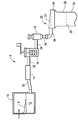
도 1은 유리시트 제조를 위한 바람직한 퓨전 유리 제조 시스템의 개략도이다.
도 2는 본 발명의 실시예에 따른 유리시트를 특성화하기 위한 장치의 사시도이다.
도 3은 장치의 아래에서 보이는 도 2의 장치의 도면이다.
도 4는 본 발명의 실시예에 따른 에지 안내 장치의 상부도이다.
도 5는 본 발명의 실시예에 따른 에지 제한 장치의 상부도이다.
도 6은 회전 엔코어와 연결된 롤러를 나타내는 도 5의 에지 제한 장치의 롤러의 측면도이다.
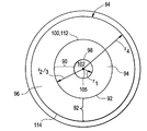
도 7은 내측 다공성 본체부와 외측 다공성 본체부를 나타내는 본 발명의 실시예에 따른 에어 베어링의 단순화된 정면도이다.
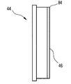
도 8은 도 7의 에어 베어링의 측면(에지)도이다.
도 9는 유리시트에 연결된 에어 베어링의 위치와 관련하여 나타난 본 발명의 실시예에 따른 에어 베어링의 정면도이다.
도 10은 도 7의 에어 베어링의 상세도이다.
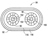
도 11은 다수의 내측 다공성 본체부를 구비하는 에어 베어링의 또다른 실시예의 정면도이다.
도 12a는 도 10의 에어 베어링의 내측 다공성 본체부 일부의 단면도이다.
도 12b는 도 10의 에어 베어링의 외측 다공성 본체부 일부의 단면도이다.
도 13은 본 발명에 따른 바람직한 리니어 에어 안정화 베어링의 사시도이며, 평면 방식으로 가늘고 긴 노즐로부터 에어의 흐름을 나타낸다.
도 14는 바람직한 에어 안정화 나이프의 아래를 향하는 각을 나타내는 도 7의 에어 베어링의 정면도이다.
도 15는 바람직한 에어 안정화 나이프의 측면 각을 나타내는 도 7의 에어 베어링의 상하면도이다.
도 16은 바람직한 에어 안정화 나이프로부터 발생되는 에어 흐름의 아랫방향을 나타내는 도 7의 에어 베어링의 측면(에지)도이다.
도 17은 유리시트의 진행방향과 관련하여 에어 베어링의 주요 및 트레일링 에지를 나타내는 도 7의 에어 베어링의 정면도이다.
도 18은 장치에 의해 유리시트에 제조된 곡률을 나타내는 도 2의 장치의 상하면도이다.
도 19는 에어 베어링에 인접한 유리시트의 곡률의 상세부를 나타내는 도 17의 에어 베어링의 일부의 단면측면도이다.
도 20은 유리시트가 100 mm/s의 속도로 진행될 때 유리시트의 두 위치에 대한 부상(fly) 높이 대 시간의 그래프이며, 유리시트 위치의 안정성을 나타낸다(즉, 부상 높이의 지속성).1 is a schematic of a preferred fusion glass manufacturing system for glass sheet production.
2 is a perspective view of an apparatus for characterizing a glass sheet according to an embodiment of the present invention.
3 is a view of the device of FIG. 2 seen from below of the device.
4 is a top view of the edge guide device according to an embodiment of the present invention.
5 is a top view of the edge limiter according to the embodiment of the present invention.
6 is a side view of the roller of the edge limiter of FIG. 5 showing the roller in connection with a rotating encore;
7 is a simplified front view of an air bearing according to an embodiment of the present invention showing an inner porous body portion and an outer porous body portion.
8 is a side (edge) view of the air bearing of FIG. 7.
9 is a front view of an air bearing according to an embodiment of the present invention shown in relation to the position of the air bearing connected to the glass sheet.
10 is a detailed view of the air bearing of FIG. 7.
11 is a front view of another embodiment of an air bearing having a plurality of inner porous body portions.
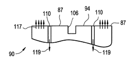
12A is a cross-sectional view of a portion of the inner porous body portion of the air bearing of FIG. 10.
12B is a cross-sectional view of a portion of the outer porous body portion of the air bearing of FIG. 10.
Figure 13 is a perspective view of a preferred linear air stabilized bearing according to the present invention, showing the flow of air from the elongated nozzle in a planar manner.
14 is a front view of the air bearing of FIG. 7 showing the downward facing angle of the preferred air stabilization knife.
15 is a top and bottom view of the air bearing of FIG. 7 showing the side angles of a preferred air stabilization knife.
FIG. 16 is a side (edge) view of the air bearing of FIG. 7 showing the downward direction of air flow resulting from the preferred air stabilization knife. FIG.
17 is a front view of the air bearing of FIG. 7 showing the main and trailing edges of the air bearing in relation to the direction of travel of the glass sheet.
18 is a top and bottom view of the apparatus of FIG. 2 showing the curvature produced in the glass sheet by the apparatus.
19 is a cross-sectional side view of a portion of the air bearing of FIG. 17 showing details of the curvature of the glass sheets adjacent to the air bearing.
FIG. 20 is a graph of fly height versus time for two positions of the glass sheet as the glass sheet progresses at a rate of 100 mm / s, indicating the stability of the glass sheet position (ie, persistence of the lift height).
다음의 상세한 설명에서, 설명과 비제한을 위하여, 상세한 설명들을 나타내는 실시예들은 본 발명의 전체적인 이해를 제공하기 위해 우선 나타난다. 그러나, 당업자들에게 본 발명의 이점을 가진 것은 명백할 것이며 본 발명은 여기에 나타난 상세 설명으로부터 멀어지는 다른 실시예에서 실행될 것이다. 게다가, 잘 알려진 장치의 상세한 설명, 방법들 및 재료들은 본 발명의 상세 설명을 불명확하게 하지 않기 위하여 생략될 수 있다. 마침내, 적용가능한 모든 곳에서 비슷한 참조번호는 비슷한 구성요소들을 나타낸다.In the following detailed description, for purposes of explanation and non-limiting, the examples showing the detailed description appear first in order to provide a thorough understanding of the present invention. However, it will be apparent to those skilled in the art having the benefit of the present invention and that the invention will be practiced in other embodiments that depart from the detailed description set forth herein. In addition, the detailed description, methods, and materials of well-known devices may be omitted so as not to obscure the description of the present invention. Finally, wherever applicable, like reference numerals refer to like elements.
예를 들어 퓨전 다운 드로우(fusion down draw) 공정과 같은 다운드로우 유리시트 제조공정에서, 유리시트는 유리리본을 형성하기 위한 점성과 드로우율의 적합한 조건 아래 수직으로 아래를 향하는 점성 유리 재료를 드로잉함으로써 형성된다. 유리리본은 리본의 최상의 위치에서 점성 액체를 구비하고 재료가 유리 전달 온도 영역을 통과할 때 점성 액체로부터 고체 유리리본까지 전달한다. 하강하는 리본의 밑면부가 적합한 온도와 점성에 도달하면, 유리시트는 리본으로부터 잘리고, 공정은 지속되며, 유리시트는 계속해서 하강하는 유리리본으로부터 잘린다.For example, in downdraw glass sheet manufacturing processes, such as fusion down draw processes, the glass sheet is drawn by drawing a viscous glass material that faces down vertically under suitable conditions of viscosity and draw rate to form a glass ribbon. Is formed. The glass ribbon has a viscous liquid at the best position of the ribbon and transfers from the viscous liquid to the solid glass ribbon as the material passes through the glass delivery temperature region. When the underside of the descending ribbon reaches the appropriate temperature and viscosity, the glass sheet is cut from the ribbon, the process continues, and the glass sheet continues to be cut from the descending glass ribbon.
퓨전 다운 드로우 유리 제조 시스템(6)이 도 1에 나타난다. 도 1에 따라, 배취 재료(8)는 용융소(10)에 적재되고 점성 용융유리 재료(12)를 형성하기 위해 가열된다. 용융유리재료(12)는 용융유리재료로부터 에어가 제거되는 정제기(14)를 통해 이송된 후 용융유리재료를 균일화시키기 위하여 교반장치(16)에서 교반된다. 교반 작동은 용융유리재료의 화학적 지속성에서 변동을 제거하기 위한 것이며, 이로써 최종 유리의 물리적 및 선택적 특성의 변동을 막는다. 용융유리재료가 교반되면, 수용용기(18)를 통해 성형체(20)로 흐른다. 수용용기(18)는 미세한 흐름 교란을 완화함으로써 축적기로써 작용한다. 성형체(20)는 본체의 상부에서 개방채널(22)을 갖는 세라믹 본체와, 성형체의 밑면에 합쳐지는 한 쌍의 수렴 외측 성형면(24) 갖는다. 용융유리재료는 성형체의 개방채널 위를 흐르고 용융유리재료의 두개의 개별적인 흐름으로써 성형체의 수렴성형면을 따라 흐른다. 용융유리재료의 개별적인 흐름은 수렴성형면이 함께 만나는 곳의 재료의 하나의 흐름 또는 리본(26)을 합치고 형성한다. 리본은 유리 전이온도 영역을 통해 하강할 때 냉각되며 유리시트(28)가 절단라인(29)을 따라 잘려짐으로써 단단한 유리리본을 형성한다.A fusion down draw glass manufacturing system 6 is shown in FIG. 1. According to FIG. 1, the
용융소(10)는 용해정제연결튜브(30)를 통해 정제소(14)와 연결되고 유체연통하며, 정제기(14)는 정제교반 장치 연결튜브(32)를 통해 교반장치(16)에 연결되고 유체연통한다. 교반장치(16)는 교반수용 용기튜브(34)를 통해 수용용기(18)에 연결되고 유체연통하며, 수용용기(18)는 다운커머튜브(36)와 성형체 유입구(38)를 통해 성형체(20)에 연결되고 유체연통한다. 용융소(10)가 통상적으로 세라믹 벽돌들(예를 들어 알루미나(alumina) 또는 지르코니아(zirconia))과 같은 세라믹 재료로 형성되는 동안, 그런 구성요소들은 용융 유리재료가 통상적으로 백금 또는 백금-로듐 합금과 같은 백금 합금으로부터 형성되는 용융유리재료를 이송하는 처리하는 것에 포함된다. 따라서, 용해정제연결튜브(30), 정제기(14), 정제교반장치연결튜브(32), 교반장치(16), 교반장치수용용기튜브(34), 수용용기(18), 다운커머튜브(36) 및 성형체 유입구(38)는 통상적으로 백금 또는 백금로듐 합금을 포함한다.The
유리시트가 유리리본(26)으로부터 제거될 때 수직으로 향하는 시트로 시작하기 때문에, 유리시트가 성형 공정의 적어도 일부의 제조 공정 다운스트림을 통해 이송될 때 수직 방향으로 유지될 수 있다면 줄어든 처리가 가능하다. 따라서, 특정 제조 공정에서 유리시트는 리본으로부터 잘려진 후 기립된 컨베이어에 부착되고 지지되며 수직 방향으로 적어도 일부의 공정라인을 통해 움직인다. 추가적으로, 유리시트가 진행하는 동안 시트를 분리하고, 시트를 고정으로 놓고, 시트를 프로세싱하고, 시트를 재장착하고 시트를 연속 공정으로 이송하는 것보다 후성형 공정을 수행하는 것이 더 효율적이다. 이를 이루기 위해, 장치는 시트가 리본으로부터 잘려진 후와 유리시트가 움직일 때 유리시트의 특성을 측정하기 위해 여기에 공개된다. 측정된 특성은 코드, 스트리크(streak) 또는 두께를 포함할 수 있다. 코드는 큰 유리의 구성의 불균일성에 관한 것이다. 이 구성의 불균일성은 주기적인 나노미터 크기의 토포그라피 편차로 이어질 수 있다. 액정 크리스탈 디스플레이(LCD) 영역에서, 이러한 편차는 디스플레이 판넬 자체에서 주기적인 셀 갭 변동으로 이어질 수 있으며, 차례로 사람 인식이 미세하게 맞춰지는 대조적인 스트리크로 이어질 수 있다. 스트리크는 LCD 판넬에서 같은 왜곡을 일으킬 수 있으나 유리시트를 형성하기 위해 사용된 본체의 흐름 왜곡에 의해 기인된다. 도 2에 따라, 장치(40)로 들어가기 전에, 유리시트는 유리시트의 윗부 에지에서만 유리시트를 고정함으로써 이송되어 유리시트는 이 지지대로부터 자유롭게 매달린다.Since the glass sheet starts with a sheet facing vertically when removed from the
상기 간단한 설명이 퓨전 다운 드로우 유리시트 제조공정에 초점이 맞춰지는 동안, 본 발명은 퓨전 다운 드로우 공정에 제한적이지 않고 슬롯 드로우 공정과 같이 다른 유리 시트 제조공정들에서 실행될 수 있다.While the above brief description focuses on the fusion down draw glass sheet manufacturing process, the present invention is not limited to the fusion down draw process and can be implemented in other glass sheet manufacturing processes such as slot draw process.
도 2와 도 3은 유리시트의 특성을 측정하기 위한 장치(40)의 바람직한 실시예를 나타낸다. 도 2와 도 3에서 나타난 바와 같이, 장치(40)는 상부 수직 방향으로 원형의 에어 베어링(44)을 지지하는 프레임(42)을 구비한다. 에어 베어링(44)은 에어 베어링의 표면으로부터 최대 편차 내에서 예정된 거리에서 유리시트로써 기판을 유지하도록 설계된 압력-진동 장치이다. 예정된 거리는 부상(fly) 높이로 언급된다. 부상 높이는 에어 베어링과 관련된 기판의 타원형 배치를 나타낸다. 에어가 하나 또는 그 이상의 진공 포트를 통해 유리시트와 에어 베어링 사이로부터 드로우될 때, 주변 에어 압력은 기판이 에어 베어링쪽을 향하도록 한다. 그러나, 기판이 에어 베어링 쪽을 향해 움직일 때, 에어 베어링의 다공성 표면으로부터 발생되는 에어에 의해 생성된 기판에 대한 힘은 증가하는데, 힘들이 평형인 위치에 기판이 도달할 때까지이다. 따라서, 기판은 에어 베어링에 의해 캡쳐되고 고정된다. 부상 높이는 주어진 소량의 부상 높이에 대하여 약간의 편차를 나타낸다. 여기에 사용된 바와 같이, 진공포트는 파이프, 튜브 또는 가스의 이송을 위한 다른 구조들과 같이 통로와 유체연통하는 에어 베어링(44)의 표면 내의 임의의 입구이며, 진공 펌프와 같이 진공원에 연결되거나 진공원에 연결되도록 의도된다. 진공 포트는 에어 베어링(44) 내에 위치된 일반적인 플레넘(plenum)을 통하거나, 에어 베어링(44) 외측의 일반적인 프레넘을 통하여 상호연결되거나, 진공으로 개별적으로 공급된다.2 and 3 show a preferred embodiment of an
에어 베어링(44)은 측정된 인접한 유리시트에 가장 가까운 면인 주요면(46)을 구비하며, 아래에서 좀더 자세히 언급되는 바와 같이 채널 또는 홈부 및 진공포트를 구비한다. 명확성을 위하여, 주요면에 대한 비스듬한 위치에 대한 참조는 원형의 에어 베어링의 외주와 관련하여 이루어질 것이며, 에어 베어링의 최상부 지점에 위치된 0도의 위치를 가지며, 360도의 시계방향 위치로 발생하는 원형의 에어 베어링의 중앙과 관련하여 비스듬한 위치를 증가시킨다.The
도 2와 관련하여, 컨베이어(48)는 유리시트의 측정이 이루어지도록 장치(40)를 통해 예정된 경로에 따른 진행(50) 방향에서 유리시트를 이송하는데 사용될 수 있다. 예를 들어, 컨베이어(48)는 레일을 따라 진행하는 클램핑 메커니즘(49)으로 채워진 오버헤드 레일을 구비할 수 있으며 또한 이것은 측정되는 유리시트의 상부 에지로 클램프된다. 바람직하게 클램핑 메커니즘은 레일을 따라 감기거나 미끄러지도록 형성된다. 게다가, 컨베이어(48)는 바람직하게 레일 어셈블리를 따라 클램핑 메커니즘, 유리시트를 이동시키는 구동 메커니즘으로 채워진다. 예를 들어, 레일 어셈블리는 구동된 체인으로 맞춰지거나 벨트가 클램핑 메커니즘에 연결되며, 모터 또는 다른 구동력은 체인 또는 벨트를 이동시키는데 사용되어, 클램핑 메커니즘을 발생시키며, 따라서 유리시트는 클램핑 메커니즘(49)에 의해 클램핑되어 레일 어셈블리를 따라 장치(40)를 통해 횡단한다. 여기에 사용된 바와 같이, 진행(50)의 방향은 장치(40)를 통해 유리시트의 전진 움직임을 나타낸다. 추가적으로, 업스트림과 다운스트림의 용어는 진행(50)의 방향과 관련하여 사용된다. 즉, 업스트림은 일반적으로 진행(50)의 방향과 반대방향으로 이해되는 반면, 다운스트림은 일반적으로 방향(50)과 같은 방향으로 이해된다. 그러나, 언급되는 방향이 필요하지 않는 업스트림과 다운스트임 지정은 동일하거나, 정확하게 진행(50)의 방향과 반대인 것을 주목해야 한다. 언급된 방향이 마주보는 방향에서 아무런 벡터 요소를 가지고 있지 않다는 것이 단지 요구된다. 예를 들어 업스트림 방향은 다운스트림 벡터 요소를 가지고 있지 않다. 추가적으로, 업스트림과 다운스트림은 이동 유리시트와 관련하여 정지위치에 대하여 사용될 수 있다. 이러한 점에서, 업스트림은 먼저 또다른 고정위치에 관한 이동 유리시트에 마주하는 위치에 관한 것이다. 따라서, 진행(50)의 유리시트 진행 방향은 연속적인 지점 또는 물체를 지나기 전에 하나의 고정된 지점 또는 물체를 지날 수 있다. 먼저 지나간 지점 또는 물체는 업스트림 지점 또는 물체가 연속적인 지점에 관한 때 관련되고, 반면에 연속적인 지점 또는 물체는 먼저 지나간 지점과 관련한 다운스트림 지점 또는 물체이다.In connection with FIG. 2, the
장치(40)는 위치된 제1 에어 안정화 나이프(52a)을 구비하는 다수의 유리시트 에어 안정화 나이프들을 더 구비하여 제1 에어 안정화 나이프는 유리시트의 제1 주요면과 마주보게 배치되며(반면에 유리시트의 제1 주요면은 에어 베어링에 가장 가깝거나 인접한 면이다), 제2 에어 안정화 나이프(52b)은 유리시트의 제2 주요면과 마주하게 배치된다, 좀더 간단히 말해서, 하나의 에어 나이프는 다른 에어 나이프가 유리시트의 또다른 또는 마주보는 면에 인접하게 위치되는 동안 유리시트의 한 면에 인접하게 위치된다. 추가적인 유리시트 에어 안정화 나이프들(52a,52b)은 그것들이 필요할 때 유리시트의 마주보는 제1 또는 제2 주요면이 되도록 위치된다. 예를 들어, 도 2와 도 3은 횡과 열로 배열된 4 쌍의 에어 안정화 나이프를 나타낸다. 장치(40)는 에어 베어링(44)의 업스트림에 배치된 에어 나이프들을 위치시키며 에어 베어링을 다운스트림을 추가적으로 구비하며 및/또는 아래에서 추가적으로 좀 더 상세히 설명된 바와 같이 에어 베어링과 관련하여 유리시트를 위치시키는 것을 돕는 에어 베어링과 마주한다.The
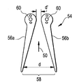
장치(40)는 또한 유리시트를 특정 지점으로 안내하기 위해 에지 안내장치(54)를 구비한다. 에지 안내장치(54)는 유리시트의 진행 방향과 관련하여 에어 안정화 나이프들의 업스트림을 위치시키며 유리시트의 측면 대 측면 흔들림을 줄이거나 제거하는 기능을 하며 에어 안정화 나이프들 사이로 유리시트를 안내한다. 도 2와 도 3에 보이며, 아마 도 4에서 가장 잘 보이는 실시예에서, 에지 안내 장치(54)는 유리시트의 낮은 에지를 수용하기 위해 안내 슬롯(58)을 형성하도록 설계된 한 쌍의 안내 암(56a, 56b)을 구비한다. 아마도 안내 슬롯(58)은 웨지 또는 V-형상이며, 안내 슬롯(58)(진행(50)의 유리시트 방향과 관련하여)의 유입(업스트림) 끝부의 안내 암들 사이의 거리(d)가 있으며 안내 슬롯으로 들어가는 유리시트는 안내 슬롯의 외측(다운스트림) 끝부에서 안내 암(56a, 56b)들 사이의 거리 d'보다 더 크다. 더 간단히 말하자면, 안내 암들 사이의 거리는 안내 슬롯의 길이와 방향(50)을 따라 변경되어 유리시트가 안내 슬롯을 따라 진행됨에 따라 안내 슬롯은 좁아지며, 이로써 에어 베어링(44)을 향한 방향으로 좁아지는 V-형상의 슬롯을 형성한다. 바람직하게, 도 4의 실시예에 나타난 바와 같이, 각각의 안내 암은 각각의 안내 암에서 추가 홀(60)로 끼워지는 축 핀 또는 볼트에 의한 프레임(42)에 회전가능하게 장착되고 프레임(42)에 고정될 수 있다. 선택적으로, 각각의 안내 암은 프레임(42)의 보충 홀 내에 끼워지는 핀을 구비할 수 있다. 따라서, 안내 암은 안내 슬롯(58)의 형상을 변화시키기 위해 회전한다. 안내 암을 고정하기 위한 수단이 또한 바람직하게 제공되어, 적합한 슬롯 형상이 보충될 때 각각의 안내 암이 고정된다. 예를 들어, 안내 암은 클램프 또는 고정 스크루에 끼워진다. 몇몇 실시예에서, 장치(40)는 다수의 에지 안내 장치(54)를 구비할 수 있다. 안내 슬롯(58)의 너비 d는 유리시트의 캡쳐를 용이하게 하기 위하여 유리시트의 가장 크게 예상되는 측면 대 측면 운동, 또는 흔들림을 수용하기 충분해야 한다(유리시트가 클램핑 메커니즘(49)에 대하여 회전하는 곳). 예를 들어, 만약 d가 충분히 넓지 않다면, 흔들리는 유리시트는 안내 슬롯(58) 내에 캡쳐되지 않을 수도 있으나 대신 장치(40)의 요소와 접촉하게 이송되어, 잠정적으로 유리시트 또는 장치를 손상시킨다. 너비 d는 특정 공정 형상의 기준에 따라 달라질 것이다. 언급된 바와 같이, 너비 d'는 너비 d보다 작으며, 유리시트가 안내 슬롯(58)을 따라 진행할 때 유리시트의 바인딩을 막기 위하여 충분히 커야 하나, 또한 측면 대 측면 흔들림이 줄어들거나 제거되게 충분히 좁아져야 한다. 너비 d'는 유리의 두께에 따라 그리고 시트에 의해 나타나는 임의의 곡률의 크기에 따라 달라진다. 선택적으로, 에지 안내 장치(54)는 블록의 윗면으로 가공되는 슬롯을 구비하는 재료의 블록일 수 있다.The
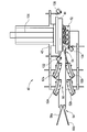
장치(40)는 바람직하게 도 5에서 잘 나타난 바와 같이, 유리시트가 에어 베어링에 인접한 제1 방향으로 움직일 때 유리시트의 밑면 에지(63)를 고정하기 위하여 또한 에지 제한 장치(62)을 구비한다. 예를 들어 에지 제한 장치(62)는 유리시트가 장치(40)를 횡단할 때 유리시트의 경로를 따라 위치된 하나 또는 그 이상의 마주하는 롤러들을 구비하는 다수의 안내 롤러 일 수 있다. 도 5의 실시예에 따라, 각각의 롤러 쌍은 고정된 배치 롤러(64)와 마주하는 이동가능한 롤러(66)를 구비한다. 롤러 쌍의 고정된 롤러는 회전가능하게 설계되나 그렇지 않으면 움직일 수 없다. 즉, 고정된 배치 롤러(64)가 롤러의 회전축에 대하여 회전할 수 있는 반면, 그것은 전이 또는 흔들릴 수 없다(아치형 묘사). 반면에, 롤러 쌍의 마주보는 이동가능한 롤러(66)는 회전가능하고 이동가능하게 설계되어 고정된 배치 롤러(64)와 마주보는 이동가능한 롤러(66) 사이의 거리는 변동가능하다. 바람직하게, 이동가능한 롤러(66)는 스프링(68)과 같은 것으로 고정된 배치 롤러(64) 쪽으로 향한다. 도 5에 나타난 바와 같이, 이동가능한 롤러(66)는 피벗점(72)에 대하여 회전하는 피벗 암(70)에 결합된다. 스프링(68)은 피벗암(70)과 스프링 정지부(74) 사이로 압축되어, 이동가능한 롤러(66)는 고정된 배치 롤러(64)를 향한다. 고정된 배치 롤러(64)와 이동가능한 롤러(66) 사이로 들어가는 유리시트(28)는 이동가능한 롤러(66)가 피벗점(72)에 대하여 회전하도록 하며 피벗점(72)에 대하여 중심위치된 원형 아크를 설명한다. 스프링(68)에 대한 피벗암(70)의 동시 이동은 스프링(68)을 더 압축한다. 측, 이동가능한 롤러(66)의 회전축은 스스로 피벗점(72)에 대하여 회전한다. 따라서, 고정된 배치 롤러(64)로부터 멀어지는 이동가능한 롤러(66)의 움직임은 피벗암(70)을 통해 스프링(68)에 의해 추출되는 힘에 의해 지지되며, 이동가능한 롤러(66)는 유리시트(28)에 대하여 작용되어 유리시트(28)는 고정된 롤러와 이동가능한 롤러 사이로 조여진다.The
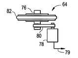
장치(40)를 통해 유리시트의 공정을 따르기 위하여, 제한 장치(62)의 적어도 하나의 롤러는 회전 롤러의 회전 움직임을 감지하고 전기 신호로 회전 움직임을 변환하기 위하여 회전 엔코더 장치를 포함할 수 있다. 도 6은 롤러축(76)과 구동 벨트(80)를 통해 롤러에 결합되는 롤러축(76)과 회전 엔코더(78)를 구비하는 고정된 배치 롤러(64)의 측면도를 나타낸다. 결합하는 회전 엔코어(78)의 다른 방법들은 이 분야에 알려진 바와 같이 채용될 수 있다. 회전 엔코더(78)는 롤러의 회전률에 따라 회전하며 전기 신호(79)를 전개시키거나 수정한다. 회전 엔코더(78)로부터 전개되거나 수정된 전기 신호(79)는 그후 평가 장치(미도시)로 이송될 수 있으며, 유리시트의 리니어 움직임은 회전 엔코더로부터 회전 데이터를 사용하여 계산될 수 있다. 도 6에서 잘 보여지는 바와 같이, 각각의 고정된 배치 롤러(64)와 각각의 이동가능한 롤러(66)는 롤러와 유리시트 사이의 접촉으로부터 발생되는 손상을 막도록 탄력면(82)을 구비한다.In order to follow the process of the glass sheet through the
이제 도 7과 도 8과 관련하여, 에어 베어링(44)은 일반적으로 평면의 주요면(46)을 구비하는 다공성 본체(84)를 구비한다. 여기에 나타난 바와 같이 다공성은 단단한 재료를 의미하나, 그러한 재료와 같은 스폰지는 외면의 홀의 일정한 분포를 발생시키는 재료의 두께를 통한 수많은 정밀한 채널을 포함하며, 각각의 구멍은 대부분 그 자체로 그리 중요하지 않다. 그러나, 다공성 재료가 압력 하에서 가스가 제공될 때 구멍은 재료의 표면으로부터 에어의 일정한 흐름을 실질적으로 함께 제공한다. 현재의 선명도를 유지하는 적합한 다공성 재료는 흑연이다. 소결된 금속 분말과 같은 다른 재료 또한 사용될 수 있으나, 흑연과 같이 더 부드러운 재료에 대한 금속의 단단한 부착성 때문에 유리 표면을 스크래치하는 위험을 추가한다. 도 9에 나타난 바와 같이, 다공성 본체(84)의 전체적인 높이 D는 통상적으로 측정된 유리시트(29)의 높이 H의 1/2를 넘지 않으며(점선(88)이 H/2를 나타내는 부분), 바람직하게 다공성 본체(84)의 높이는 유리시트의 1/3을 넘지않거나 그 이하이며, 유리시트의 높이는 유리시트가 컨베이터(48)로부터 수직으로 매달릴 때 수직 방향의 유리시트 치수이다. 게다가, 또한 도 9에 나타난 바와 같이, 작동 중에 에어 베어링은 유리시트의 밑면부에만 인접하게 배치되는 것이 바람직하다. 즉, 에어 베어링은 바람직하게 다공성 본체(84)가 유리시트의 1/2 이하 또는 그 높이 또는 그 높이에만 인접하도록 위치된다. 다공성 본체(84)나 유리시트(예를 들어 점선(88) 이상)에 높게 위치된다면, 유리시트는 메커니즘을 클램핑하는 두개의 컨베이어에 의해 유리시트에 배치된 제한으로부터 기인된 지나친 스트레스를 받을 수 있고 상기 제한은 에어 베어링에 의해 적용된다. 발생되는 스트레스는 유리시트를 부술 수 있다.With reference now to FIGS. 7 and 8, the
도 7은 다공성 본체(84)는 첫번째, 또는 내측 다공성 본체부(90)와 제2, 또는 내측 다공성 본체부에 배치된 외측 다공성 본체부(92)로 분리될 수 있다. 따라서, 평평한 주요면(46)은 내측 다공성 본체(90)를 구비하는 내측 평면(94)으로 나누고, 외측 평면(96)은 외측 다공성 본체부(92)를 구비한다. 내측 평면(94)과 외측 평면(96)은 동일평면상이다.7 illustrates that the
에어 베어링(44)의 내측 다공성 본체부(90)는 환형이며, 내주의 중심으로부터 반지름 r1으로 정의되는 환형의 내주(98)를 갖고 내주의 중심으로부터 반지름 r2로 정의되는 외주(100)을 갖는다. 추가적으로, 내주(98)는 에어 베어링(44)을 통해 뻗는 통로(102)의 외주를 나타낸다. 통상적인 실시예에서, 통로(102)는 직경이 약 3cm 에서 약 8cm 까지의 범위에 있다. 그러나, 통로(102)는 더 크거나 더 작으며, 실행되는 측정의 필요와 속성에 따라 달라진다. 측정장치(104)(도 2 참조)는 에어 베어링(44)이 유리시트(28)와 측정장치(104) 사이에 위치되도록 배치되며 측정장치의 광학축(105)은 통로(102)를 통해 뻗는다. 그러한 "통과" 측정은 검사의 평면(측정장치(104)에 의해 고정)과 유리의 평면이 동일평면상인 것이 이롭다. 예를 들어 광학축(105)은 도 7에 보이는 바와 같이 내주(98)의 중심과 일치한다. 다른 실시예에서, 측정장치(104)는 유리시트(28)가 측정장치(104)와 에어 베어링(44) 사이에 있도록 위치된다. 그럼에도 불구하고, 측정장치(104)는 여전히 측정장치의 광학축(105)이 경로(102)를 따라 지나가도록 정렬되게 배치되어야 한다. 그러나, 특정 실시예에서, 다공성 본체(84)로부터의 오른쪽 반사가 수행되는 특정한 측정의 질에 영향을 끼치지 않거나 그렇지않고 간섭한다면 다공성 본체(84)에 접하는 유리시트(28)의 측면으로부터 측정이 이루어질 때 제거될 수 있다. 측정 장치(104)의 광학축(105)은 예를 들어 유리시트(28)를 향한 측정장치에 의해 생략되는 레이저 빔일 수 있다.The inner
이제 도 10과 관련하여, 내측 다공성 본체부(90)는 내주(98)와 동심인 적어도 하나의 원형 홈부(106)를 구비한다. 내측 다공성 본체부(90)는 내측 평면(94)에 방사형으로 뻗어있는 다수의 홈부(108)를 더 구비하고 원형 홈부(106)를 교차한다. 방사형 홈부(108)는 바람직하게 스포크와 같은 방식으로 주기적인 각도 지점에 배열된다. 환형 홈부(106)와 교차하는 방사형 홈부(108)는 내측 평면(94)을 다수의 서브 표면(87)으로 분리한다. 각각의 서브-표면(87)은 상기 언급한 바와 같이 진공원(미도시)에 유체연통하는 적어도 하나의 진공 포트(110)를 구비한다.Referring now to FIG. 10, the inner
내측 다공성 본체부(90)와 같이, 에어 베어링의 외측 다공성 본체부(92)는 아치형상이나, 원형의 외주를 가질 필요는 없다. 예를 들어 외측 다공성 본체부는 타원형 또는 달걀형상이다. 외측 다공성 본체부(92)는 내측 다공성 본체부(90) 근처에 배치되며 상기 언급된 내측 다공성 본체부(90)의 중심으로부터 반경 r3으로 정의된 원형의 내주(112)를 구비한다. 외측 다공성 본체부(92)가 원형의 외주, 즉, 도 7에 보이는 원주(114)를 구비하는 실시예에서, 외주(114)는 내주(98)의 중심으로부터 반경 r4로 정의된다. 몇몇 실시예에서, r2=r3이며 그러므로 외측 다공성 본체부(92)의 내주(112)는 내측 다공성 본체부(90)의 외주(100)와 같다.Like the inner
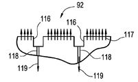
여전히 도 10과 관련하여, 외측 다공성 본체부(92)는 외측 평면(96)에 형성된 다수의 연속적인 홈부(116)를 더 구비한다. 각각의 연속적인 홈부(116)는 다공성 본체를 통해 연장하는 다수의 진공 포트(118)를 구비하며 진공원에 연결된다. 바람직하게, 다수의 진공포트(118)는 주어진 연속적인 홈부에 배치된 진공 포트들 사이의 각 배치가 동일해지도록 각각의 연속적인 홈부(116) 내에 주기적으로 배열된다. 예를 들어, 주어진 연속적인 홈부(116) 내에서, 진공포트(118)는 홈부 근처에서 5도, 10도 또는 15도 마다 배치될 수 있다. 하나의 연속적인 홈부(116)의 진공포트는 또다른 연속적인 홈(116)의 진공포트와 비스듬하게 일치할 필요가 없다. 몇몇 케이스에서, 특히 외측 다공성 본체부(92)의 외주가 원형이면, 연속적인 홈부(116)는 특히 원형이며 동심이다.Still referring to FIG. 10, the outer
도 11에 나타난 바와 같이 몇몇 실시예에서, 에어 베어링(44)은 외측 다공성 본체부(92) 내에 위치된 다수의 내측 다공성 본체부(90)를 구비하며, 각각의 내측 다공성 본체부는 통로(102)를 형성한다. 이것은 유리시트의 동시에 결정하는 다양한 특성을 위한 여러개의 측정들이 실시되고 하나의 측정 장치로 병합되지 않을때 특히 도움이 될 수 있다.In some embodiments, as shown in FIG. 11, the
홈부와 진공포트의 조직은 도 12a와 도 12b에 의해 더 잘 보일 수 있으며, 도 12a는 내측 다공성 본체부(90)의 일부의 단면도를 나타내고, 도 12b는 외측 다공성 본체부(92)의 일부의 단면도를 나타낸다. 두 내측 다공성 본체부(90)와 외측 다고성 본체부(92)는 에어와 같은 압축된 가스로 압축되며, 화살표 117에 나타난 바와 같이 각각의 다공성 본체부의 평면으로부터 발생한다. 이와 함께, 화살표 119에 나타난 바와 같이 진공 포트에서 생성되며 에어압은 두 영역: 외측 평면(96)에 인접한 저정밀 캡쳐존과 내측 평면(94)와 일치하는 고정밀 캡쳐존을 형성하는 다공성의 본체부의 평면에서 생성된다. 저정밀 캡쳐 존에서 유리시트의 부상 높이는 고정밀 캡쳐존에 인접한 유리시트의 부상 높이보다 더 크다. 저정밀 캡쳐존에 인접한 유리시트의 부상 높이는 통상적으로 약 40㎛ 에서 60㎛의 범위에 의할 수 있으나, 반면에 고정밀 존에 인접한 유리시트의 부상 높이는 통상적으로 40㎛일 수 있다.The tissue of the groove and the vacuum port can be better seen by FIGS. 12A and 12B, where FIG. 12A shows a cross-sectional view of a portion of the inner
도 2와 도 3의 실시예에 따라 상기 언급한 바와 같이, 장치(40)는 장치(40)를 통해 유리시트(28)의 진행(50) 방향과 관련하여 에어 베어링(44)의 업스트림에 위치된 다수의 에어 안정화 나이프들(52a, 52b)을 포함한다. 다수의 에어 안정화 나이프들은 제1 에어 안정화 나이프가 유리시트(28)(도 18 참조)의 마주하는 제1 주요면(121)에 위치되도록 배치된 제1 에어 안정화 나이프(52a)와, 제2 에어 안정화 나이프가 유리시트(28)의 제2 주요면(123)과 마주하게 위치되도록 배치된 제2 에어 안정화 나이프(52b)를 구비한다. 유리시트(28)의 제1 주요면(121)은 유리시트가 에어 베어링에 인접할 때 다공성 본체(84)에 가장 가까운 유리시트의 표면인 반면, 제2 주요면(123)은 같은 조건에서 다공성 본체(84)로부터 가장 먼 유리시트(28)의 표면이다. 다수의 에어 안정화 나이프들의 적어도 제1 및 제2 에어 안정화 나이프들로부터의 에어 흐름은, 유리시트가 에어 안정화 나이프들 사이의 공간에 들어갈 때 적어도 하나의 에지 안내 장치(54)와 인접한 유리시트의 측면(측면 대 측면) 움직임을 안정화하고 시트가 평탄해지는 것을 돕는다. 좀 더 간단히 말해서, 비록 유리시트가, 유리시트의 윗면 에지의 컨베이어 클램핑 메커니즘(49)과 유리시트의 하부 에지의 에지 안내장치(54)에 의해 유리시트의 상부 및 하부의 측면 운동으로부터 방해받는다 할지라도, 유리시트는 여전히 유리시트의 일반적인 면에 수직인 방향으로 변형되며, 대체로 크로스 세일은 바람에 굽이칠 수 있다. 이것은 유리시트가 매우 크고 매우 얇을 수 있기 때문이며, 더 두꺼운 유리 플레이트와 비교할 때 유리시트에 증가된 유연성을 준다. 예를 들어, 유리시트의 두께는 1mm 이하일 수 있다.As mentioned above in accordance with the embodiment of FIGS. 2 and 3, the
각각의 에어 안정화 나이프는 각각의 에어 안정화 나이프로부터의 에어 흐름이 하부 방향의 유리시트 쪽을 향하도록 방향설정되며, 일반적으로 유리시트의 밑면을 향하며, 유리시트의 주요면 위로 에어의 더 많은 라미나(laminar) 흐름을 생성하며, 유리시트의 요동 및 연속적인 난타를 방지한다. 바람직하게, 비록 불필요하다할지라도, 제1 및 제2 에어 안정화 나이프들(52a, 52b)는 유리시트를 지나 서로 대칭으로 배치된다. 예를 들어, 도 2와 도 3과 같은 몇몇 실시예에서, 다수의 에어 안정화 나이프들은 여러쌍의 부분적 또는 연속적으로 마주하는 에어 나이프들로 바람직하게 배치된다. 즉, 에어 나이프들이 서로 직접 마주하는 동안, 이것이 불필요하지만, 에어 나이프들의 그러한 "쌍들" 사이의 약간의 오프셋일 수 있다. 그러나, 몇몇 실시예에서 오프셋은 실질적이다. 에어 안정화 나이프의 수는 공정에 따르며, 예를 들어 유리시트의 전달속도에 따를 것이며, 유리시트의 크기 무게 및 측면-대-측면 흔들림의 양은 특히 제조 공정 라인에서 유리시트에 의해 나타난다. 유사하게, 유리시트의 한쪽 면의 하나의 에어 나이프에 비교된 유리시트의 다른 면의 에어 나이프의 정확한 배치는 설치의 특정 공정 조건에 따라 달라진다.Each air stabilization knife is directed so that the air flow from each air stabilization knife is directed toward the glass sheet in the downward direction, generally toward the bottom of the glass sheet, and more lamina of air over the main surface of the glass sheet. It creates a laminar flow and prevents rocking of the glass sheet and subsequent blows. Preferably, although unnecessary, the first and second
도 13은 에어 발생의 흐름(126)으로부터 가늘고 긴 오리피스(124)를 갖는 일반적으로 가늘고 긴 본체(122)를 구비하는 바람직한 에어 안정화 나이프(여기서는 일반적으로 참조번호 120으로 나타남)을 나타낸다. 단순함을 위하여, 에어 나이프는 길이방향으로 뻗어있는 직사각형 블록으로 나타난다. 각각의 가늘고 긴 오리피스(124)는 결합을 통해 에어 나이프로 들어가는 압축된 가스 공급원과 유체연통한다. 에어 나이프는 오리피스(124)와 유체연통하는 내측 플레넘을 포함한다. 에어는 풍부하면서 본질적으로 자유로운 가스로 에어를 사용하는 것이 매우 만족스럽기 때문에, 남은 설명은 에어 기반의 에어 나이프를 가정할 것이다. 각각의 가늘고 긴 본체(122)는 각각의 가늘고 긴 오리피스(124)로부터 방사된 에어의 흐름방향이 참조된 수평면과 관련하여 아래방향의 각이 되도록 배치된다. 바람직한 에어 안정화 나이프(12)에 의해 나타나는 바와 같이 각각의 에어 안정화 나이프는 유리시트의 진행(40)의 방향과 관련하여 앞쪽 또는 선단 끝부(L) 및 뒤쪽 또는 트레일링 끝부(TR)을 포함한다. 즉, 에어 나이프의 선단 에지는 에어 나이프의 트레일링 끝부보다 더 먼 업스트림이다. 에어 나이프가 압축된 에어로 제공될 때 에어는 높은 점성으로 가늘고 긴 오리피스(124)로부터 발생된다. 가늘고 긴 오리피스(124)로부터의 에어 발생은 에어 안정화 나이프가 그대로 있는 후에 마침내 발산되기 시작하며, 약 수십 밀리미터의 적어도 짧은 거리에 대하여, 실질적으로 라미나 흐름(126)이 평면에 의해 측정될 때 에어 나이프로부터 에어가 발생한다. 바람직한 에어 안정화 나이프(120)은 상면(T)를 더 포함한다.FIG. 13 shows a preferred air stabilization knife (generally indicated at 120) with a generally
에어 안정화 나이프가 상보적으로 마주하는 관계로 배열될 경우(즉, 에어 베어링 주요면(46)과 평행인 에어 안정화 나이프들 사이의 중앙 수직면을 지나 대칭됨), 마주하는 에어 안정화 나이프 쌍의 끝단부 사이의 거리는 마주하는 에어 안정화 나이프 쌍의 트레일링 끝부 사이의 거리보다 더 클 수 있다. 즉, 에어 안정화 나이프들 사이의 거리는 안내 슬롯(58)의 좁아짐과 비슷한 방식으로 에어 나이프들 사이로 유리시트가 진행함에 따라 좁아진다. When the air stabilizing knives are arranged in complementary facing relationship (ie, symmetrical across the central vertical plane between the air stabilizing knives parallel to the air bearing main face 46), the ends of the pair of opposing air stabilizing knives The distance between can be greater than the distance between the trailing ends of the opposing air stabilizing knife pair. In other words, the distance between the air stabilizing knives narrows as the glass sheet progresses between the air knives in a manner similar to the narrowing of the
여전히 또다른 선택적인 특성에서, 다수의 에어 안정화 나이프들의 각각의 에어 안정화 나이프는 각각의 에어 안정화 나이프의 트레일링 끝부가 에어 안정화 나이프의 끝단부보다 더 높아지도록(또는 더 낮아지도록) 방향설정된다. 몇몇 실시예에서, 각각의 에어 안정화 나이프는 바람직한 에어 나이프(120)과 비슷하게 일직선이다(즉, 직사각형상). 그러나, 바람직하게 각각의 에어 안정화 나이프는 아치형이고 원형 아크를 구비할 수 있다. 일직선(선형)의 다양성 또는 아치형 설계 중 하나의 적합한 에어 안정화 나이프들은 예를 들어 미국, 오하이오, 신시나티(Cincinnati)에 위치된 이자이어 코포레이션(Exair Corporation)을 통해 얻을 수 있다.In yet another optional feature, each air stabilization knife of the plurality of air stabilization knives is oriented such that the trailing end of each air stabilization knife is higher (or lower) than the end of the air stabilization knife. In some embodiments, each air stabilization knife is straight (ie rectangular) similar to the
각각의 에어 안정화 나이프가 어떻게 공간적으로 방향성을 갖는가 하는 것은 다음의 설명과 도면 14 내지 16으로 더 자세히 보여질 수 있다. 3차원 공간의 본체 방향성은 참조 프레임과, 참조 프레임에서 본체를 향하는 수단을 필요로 한다. 도 14는 다공성 본체(84)의 주요면(46)과 동일선상인 수직의 X-Y 평면을 나타낸다. 추가적인 설명을 위하여, 이 X-Y 평면은 3차원의 직교 좌표 참조 프레임에서 한 평면을 형성한다. 이 X-Y 평면은 도 14가 나타난 페이지의 평면 내에 놓인다. 도 14의 에지로부터 보이는 제2 수직 평면은 Z방향이 수직으로 뻗어있어 영역을 벗어나는 직교 좌표 시스템의 Y-Z 평면을 형성한다. Y-Z 평면은 X-Y 평면에 대하여 수직이다. 세번째인 X-Z 평면은 도 14의 에지로부터 또한 보여지며, X-Y 평면과 Y-Z 평면 둘다에 수직으로 배치된다. 추가적인 설명을 위하여, 그리고 만약 그럼에도 불구하고 서술되지 않는다면, 직교 좌표 시스템의 중심은 내측 다공성의 본체부(90)의 중심에 놓인 상기의 제3 평면 X-Y, Y-Z 및 X-Z 에 의해 형성되며, 이 직교 좌표 시스템은 3차원 공간에서 에어 나이프들의 방향성을 설명하는데 사용될 것이다.How each air stabilizing knife is spatially directional can be seen in more detail in the following description and in figures 14-16. Body directionality in three-dimensional space requires a reference frame and a means from the reference frame to the body. 14 shows a vertical X-Y plane that is collinear with the
도 14 내지 16은 바람직한 에어 안정화 나이프(120)의 3개의 선택적인 방향성을 나타내는데, 각각의 에어 안정화 나이프의 선택적인 에어 방향성의 연장에 의한 것이며, 방향성의 가시화를 돕기위해 분리되어 나타난다. 도 14는 주요면(46)에서 보이는 바와 같이 에어 베어링(44)의 바깥선을 나타내며, 유리시트의 진행(50) 방향을 나타낸다. 바람직한 에어 안정화 나이프(120)은 아래를 향하는 핀치를 나타내거나 에어 안정화 나이프의 끝단부(L)의 기울어짐은 수평 X-Z 평면과 관련하여 에어 안정화 나이프의 트레일링 끝부(TR)보다 더 낮다. 즉, 바람직한 에어 정화 나이프로부터의 에어 흐름을 나타내는 평면(128)은 X-Z 평면에 대해 각도 α를 만든다.14-16 show the three optional directionalities of the preferred
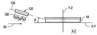
도 15는 에어 베어링(44)의 에지 아래에서 보는 제2 도면과 Y-Z 평면의 에지와 X-Y 평면의 에지를 나타낸다. X-Z 평면은 X-Y 평면과 Y-Z 평면에 대하여 직각이다. 평면(130)은 바람직한 에어 안정화 나이프(120)의 길이방향으로 이분하는 상부면(T)이며 에어 나이프로부터의 에어 흐름을 나타내는 평면(126)에 대하여 직각이다. 도 15에 따라, 바람직한 에어 안정화 나이프(120)은 수직의 X-Y 평면에 대하여 기울어져 0이 아닌 각도 β가 평면(130)과 X-Y 평면 사이에 형성된다.15 shows a second view under the edge of the
도 16은 에어 베어링(44)의 에지를 아래에서 본 제 3의 도면이며 X-Z 평면의 에지와 X-Y 평면의 에지를 나타낸다. Y-Z 평면은 X-Y 평면과 X-Z 평면 둘다에 수직이다. 도 16은 에어 나이프가 존재하는 에어 흐름이 아래를 향하게 기원이 된 끝부로부터의 바람직한 에어 정화 나이프(120)을 나타내며(예를 들어 수평 X-Z 평면에 평행인 관련된 수평 방향으로부터) 에어 흐름의 평면은 직접적이기보다 X-Y 평면에 대하여 아치형 각도 δ를 만드는데, 예를 들어 유리시트에 수직이다. 바람직하게, δ는 약 15도에서 약 75도 사이의 범위이며, 바람직하게 약 25도에서 약 65도 사이의 범위이며, 특히 약 35도 에서 약 55도의 범위이다. 일 실시예에서, 에어 흐름의 각도는 수직 X-Y 평면에 대하여 약 45도이다. 에어 흐름의 바람직한 방향은 아래를 향하는 것을 주목해야 하며, 유리시트와 관련된 에어 베어링의 낮은 배치는 에어 흐름에 따른 유리시트의 고정을 지지하기 위하여 유리시트의 낮은 부분을 더 단단하게 만든다. 그러나, 몇몇 실시예에서, 에어 흐름의 상향은 공정 환경과 특정 실행, 예를 들어 에어 베어링의 배치에 따라 선호된다.FIG. 16 is a third view from below of the edge of the
공정 설명은 바람직한 에어 안정화 나이프(120)의 3개의 선택적인 방향성을 나타낸다. 다수의 에어 안정화 나이프들의 각각의 에어 안정화 나이프는 대표적으로 바람직한 에어 안정화 나이프과 관련하여 상기에 나타난 3개의 선택적인 방향성 중 적어도 하나의 방향성을 나타낼 수 있다. 예를 들어, 다수의 에어 안정화 나이프 중 각각의 에어 안정화 나이프는 에어 나이프로부터의 에어 흐름이 일반적으로 아래를 향하도록 에어를 방출한다(즉, 흐름 벡터는 수직 벡터 요소를 구비한다). 따라서, 예를 들어, 두개의 에어 안정화 나이프들은 유리시트의 마주보는 면들에 위치되며 에어 안정화 나이프들은 서로 대칭하는 이미지이며, 일반적으로 V 형상의 에어 흐름을 형성하며 "V"를 나타내며 아래를 향한다.The process description shows three optional orientations of the preferred
유사하게, 다수의 에어 안정화 나이프들의 각각의 에어 안정화 나이프는 각각의 에어 안정화 나이프의 끝단부가 트레일링 끝부보다 유리시트로부터 더 멀어지도록 방향설정된다. 따라서, 예를 들어, 두개의 에어 안정화 나이프들은 유리시트의 마주보는 면들에 위치되며 에어 안정화 나이프들은 서로 대칭되는 이미지이며 일반적으로 에어의 V 형상의 흐름을 형성하며 "V"를 나타내며 에어 베어링 쪽으로 아래를 향한다. 이것은 유리시트가 에어 나이프들 사이로 들어갈 때 측면 이동을 나타내는 유리 시트에 대한 더 많은 측면 공차를 제공한다. 이것은 또한 에어 안정화 나이프로부터 특정 에어 흐름의 더 점진적인 적용을 제공하는데, 각각의 에어 안정화 나이프의 끝단부로부터의 에어 흐름으로부터의 유리시트의 압력은 에어 안정화 나이프의 트레일링 끝부에 인접한 유리시트의 에어 압력보다 작아진다.Similarly, each air stabilization knife of the plurality of air stabilization knives is oriented such that the end of each air stabilization knife is further from the glass sheet than the trailing end. Thus, for example, two air stabilizing knives are located on opposite sides of the glass sheet and the air stabilizing knives are images that are symmetrical to each other and generally form a V-shaped flow of air and represent "V" and down towards the air bearing. Heads up. This provides more side tolerances for the glass sheet that exhibit lateral movement as the glass sheet enters between the air knives. This also provides a more gradual application of the specific air flow from the air stabilization knife, where the pressure of the glass sheet from the air flow from the end of each air stabilization knife is the air pressure of the glass sheet adjacent to the trailing end of the air stabilization knife. Becomes smaller.
유사하게, 다수의 에어 안정화 나이프 중 각각의 에어 안정화 나이프는 각각의 에어 안정화 나이프의 끝단부가 트레일링 끝부보다 수평 참조면(예를 들어, X-Z 평면)과 관련하여 더 작도록 방향설정될 수 있다. 이것은 에어 안정화 나이프가 시트의 임의의 형상 왜곡(예를 들어 바우)을 평평하게 하도록 조이거나 앞쪽으로 기울어진다. Similarly, each air stabilization knife of the plurality of air stabilization knives may be oriented such that the end of each air stabilization knife is smaller with respect to the horizontal reference plane (eg, X-Z plane) than the trailing end. This is caused by the air stabilizing knife being tightened or tilted forward to flatten any shape distortion (e.g. bow) of the seat.
다수의 에어 나이프 중 각각의 에어 안정화 나이프는 상기 언급된 하나 또는 그 이상의 방향성을 나타낼 수 있다. 몇몇 실시예에서, 하나 또는 그 이상의 에어 안정화 나이프들은 동시에 모든 세개의 방향성을 나타낼 수 있다.Each air stabilizing knife of the plurality of air knives may exhibit one or more of the aforementioned orientations. In some embodiments, one or more air stabilizing knives may exhibit all three orientations at the same time.
예를 들어 에어 안정화 나이프들에 추가적이며 도 3에 보이는 바와 같이, 제1 에어 안정화 나이프(132)은 에어 안정화 나이프들(52a, 52b)과 에어 베어링(44) 사이에 위치될 수 있어 제1 에어 배치 나이프로부터의 에어의 흐름(126)은 에어 베어링의 선단 에지에 인접한 유리시트의 제1 주요면(121)을 방해한다. 예를 들어, 제1 에어 배치 나이프(132)는 에어 베어링(44)에 약 270도 위치로 배치될 수 있다. 유리시트가 제1 에어 배치 나이프(132)에 인접하여 지날 때 유리시트에 생성된 압력은 유리시트를 에어 베어링으로부터 멀어지게 한다. 이것은 유리시트가 에어 베어링에 의해 "캡쳐"될 수 있을 때까지 에어 베어링에 접근함으로써 유리시트의 끝부 또는 앞쪽 에지 사이의 접촉을 방지한다.For example in addition to the air stabilization knives and as shown in FIG. 3, the first
제2 에어 배치 나이프(134)은 제2 에어 배치 나이프로부터의 에어가 유리시트의 제2 주요면(123)에 영향을 주로고 배치된다. 제2 에어 배치 나이프로부터의 에어의 효과는 유리시트를 에어 베어링의 앞쪽 방향을 향하도록 하는 것이며, 따라서 유리시트는 에어 베어링에 더 가까워지고 에어 베어링이 유리시트를 캡쳐하도록 한다. 유리시트의 첫번째 캡쳐는 외측 다공성 본체부에 의해 생성된 압력과 진공의 혼합에 의해 이루어진다. The second
제3 에어 배치 나이프(136)은 에어 베어링으로부터 아래쪽으로 배치되고 제3 에어 배치 나이프에 의해 방사된 에어가 유리시트의 제1 주요면(121)을 향하도록 배치된다. 제3 에어 배치 나이프(136)에 의해 생성된 에어 압력은 유리시트를 에어 베어링의 다운스트림 에지 근처의 에어 베어링 표면으로부터 멀어지도록 하며 이로써 유리시트가 에어 베어링을 지나도록 움직이고 분리될 때 유리시트와 에어 베어링 사이의 접촉을 막는다. 각각의 에어 배치 나이프(132,134,136)는 에어 안정화 나이프과 비슷한 설계일 수 있다. 예를 들어, 각각의 에어 안정화 나이프과 각각의 에어 배치 나이프는 아치평상 또는 리니어 형상일 수 있다. 바람직하게, 에어 배치 나이프들(132,134,136)로부터 방사된 에어는 유리시트를 향하여 각각의 에어 배치 나이프들로부터의 가스 커튼은 90도 이하의 각을 형성하나 유리시트의 표면에 대하여 0 이상이며, 예를 들어 25도 이상 75도 이하이며, 바람직하게 35도 이상 65도 이하이며, 바람직하게 35도 이상 55도 이하이다. 예를 들어, 통상적인 실시예는 각각의 에어 배치 나이프들을 향할 수 있어 에어의 흐름은 약 45도의 각도로 유리시트에 충돌이 된다. 90도 이하의 충돌의 각도는 예를 들어 유리시트와 수직인 에어 흐름보다 유리시트의 표면에서 더 작은 교란을 생성한다.The third
장치(40)의 다양한 비접촉식 유리시트 처리 요소의 전체적인 효과는 측정을 위해 유리시트를 준비하기 위해 유리시트에 점진적으로 증가하는 제한을 제공하는 것이다. 이미 언급된 바와 같이, 몇몇 예에서 유리시트는 수직으로 이송되고, 이송 클램프에 의해 유리시트의 상부면에서만 고정된다. 유리시트가 매우 얇고, 1mm 거나 그 이하이거나, 몇몇의 경우 0.7mm이거나 그 이하이거나, 몇몇의 다른 경우 0.3mm이거나 그 이하일 때, 유리는 흔들리는 측면 대 측면(즉, 고정된 이송 접촉점에 대해 회전암)에 의해 측면 이동을 쉽게 나타낼 수 있거나, 다양한 벤딩 모드에 의해 변경된다(여기에 나타난 바와 같이, 벤딩 모드는 진동 모드에 대해 아날로그임). 유리는 또한 클램핑에서 이송 대 이송 변동과 컨베키어의 이송 위치때문에 오프셋 될 수 있다. 또한, 유리는 수직으로 굽혀질 수 있다.The overall effect of the various non-contact glass sheet processing elements of the
장치(40)의 다양한 유리시트 처리 요소는 이러한 움직임 및 바우와 같이 고정된 형상을 줄이거나 제거하는 것을 돕는다. 따라서, 장치(40)의 작동은 다음의 단계에 따라 진행될 수 있다The various glass sheet processing elements of the
유리시트(28)는 장치(40)를 통해 유리시트를 전달시키는 유리시트의 상부 에지를 따라 유리시트를 잡는 하나 또는 그 이상의 클램핑 메커니즘(49)에 의해 컨베이어(48)에 부착된다. 유리시트(28)는 따라서 하나 또는 그 이상의 클램핑 메커니즘들로부터 걸리고, 유리시트의 상부를 따라 유리시트에 클램핑되는 하나 또는 그 이상의 클램핑 메커니즘에 의해서만 지지된다. 유리시트의 낮은 에지(63)는 지지되지 않고 장치(40)를 들어가기 전에 처음에 측면 이동, 즉 흔들림 이동을 사용한다. 측면 이동에 추가적으로, 유리시트는 또한 만곡부 또는 벤딩을 나타낼 수 있다. 예를 들어, 시트는 원통형상 또는 쌍곡형상 또는 새들(saddle), 돔 형상일 수 있거나 다른 벤딩 모드 또는 그러한 복합체들을 나타낸다. The
유리시트(28)가 장치(40)로 들어감에 따라, 유리시트는 유리시트의 낮은 에지(63)에 연결된 적어도 하나의 에지 안내장치(54)에 의해 안내되며 에어 스트라이킹 나이프들(52a, 52b) 사이의 유리시트의 선단 에지를 안내한다. 낮은 에지(63)는 유리시트의 "비우수" 부분의 일부를 형성하며 나중에 제거될 수 있다. 적어도 하나의 에지 안내 장치(54)는 측면 대 측면 흔들림을 최소화하거나 제거한다. 여기에 나타난 바와 같이 에지 안내 장치(54)의 실시예를 보여주는 시험은 +/-75mm 부터 +/-10mm 이하의 최대 배치로부터의 흔들림의 측면 운동을 줄일 수 있다. 그러나, 적어도 하나의 안내 장치(54)는 유리시트의 낮은 에지의 측면 이동의 우수한 제어를 제공할 수 있으며, 유리시트는 단지 실질적으로 상부 및 하부 에지에만 제한되며, 여전히 다양한 벤딩 모드와 유리시트의 본체 내에서 고정된 형상을 나타낼 수 있다. 유리시트를 다공성 본체(84)로 인접하게 움직이기 전에 유리시트의 이러한 추가적인 움직임 또는 형상을 최소화하거나 제거하기 위하여 에어 안정화 나이프들이 채용된다.As the
바람직하게는 아래방향으로 마주하는 에어 안정화 나이프들에 의해 방사되는 에어 흐름은 유리시트의 측면 대 측면 흔들림을 제거하기 위해 유리시트의 측면 이동을 더 줄일 수 있으며, 특히 벤딩 모드를 줄이거나 제거한다. 실제로, 에어 안정화 나이프들은 벤딩의 크기를 적어도 줄임으로써 유리시트를 단단하게 하는 것을 돕고 몇몇 예에서는 하나 또는 다른 벤딩 모드를 제거함으로써 실행된다. 에어 안정화 나이프들의 개수 및 위치는 유리시트의 크기, 유리시트의 두께, 유리의 밀도와 같은 그러한 요소에 따라 달라지며, 장치(40)를 통해 유리시트의 속도를 횡단한다.Preferably the air flow radiated by the downward facing air stabilizing knives can further reduce the lateral movement of the glass sheet to eliminate side to side shake of the glass sheet, in particular reducing or eliminating the bending mode. In practice, air stabilizing knives are performed by helping to harden the glass sheet by at least reducing the size of the bending and in some instances by eliminating one or another bending mode. The number and position of the air stabilizing knives depend on such factors as the size of the glass sheet, the thickness of the glass sheet, the density of the glass, and traverse the speed of the glass sheet through the
유리시트가 에어 안정화 나이프들 사이를 지나갈 때, 유리시트의 낮은 에지(63)는 유리시트를 더 안내하고 안정화하기 위해 하나 또는 그 이상의 추가적인 에지 안내 장치(54)에 의해 안내될 수 있다. 예를 들어, 몇몇 실시예에서, 다수의 에지 안내 장치들은; 에어 안정화 나이프들의 업스트림을 채용한 제1 에지 안내 장치와 에지 제한장치(62)에 단지 앞서 위치된 제2 에지 안내 장치를 채용할 수 있다.As the glass sheet passes between the air stabilizing knives, the
유리시트가 에어 베어링(44)에 접근할 때, 선택적인 제1 에어 배치 나이프(132)는 유리시트의 제1 주요면(121)의 에어의 흐름을 향하는데 사용될 수 있다. 유리시트(28)의 제1 주요면(121)에 대한 제1 에어 배치 나이프(132)로부터의 에어힘은 에어 베어링(44)의 선단 에지(140)(도 17, 특히 도 18의 영역 A 참조)로부터 유리시트를 멀리 밀며 에어 베어링의 선단 에지(140)와 유리시트(28)의 선단 에지(141) 사이의 접촉을 막는데 이때 유리시트는 에어 베어링(44)의 외측 다공성 본체부(92)의 영향 아래에 있다. 유리시트와 에어 베어링 사이의 접촉은 몇몇 예시의 격변성에서 유리시트에 대한 손상을 초래할 수 있다.When the glass sheet approaches the
유리시트가 진행(50)의 방향을 따라 앞으로 지속적으로 움직임에 따라 유리시트는 외측 다공성 본체부(92)의 제1 진공포트(118)를 지날 수 있다. 바람직하게, 에어 베어링(44)은 유리시트가 전진함에 따라 외측 다공성 본체부(92)의 최외측 홈부 내에 위치된 진공 포트(118)가 위치되도록 배치된다. 이것은 먼저 이 하나의 진공 포트(118)에 인접하게 움직인다. 도 10과 관련하여, 이 제1 진공 포트(118)는 왼쪽으로 가장 멀며 도 8의 최외측 연속홈부(116)에 놓인 진공 포트이며 점선(119)과 교차한다. 제1 진공 포트(118)와 처음으로 마주하는 효과는 유리시트(28)의 선단 에지(141)가 외측 다공성 본체(92)에 더 가깝게 움직이는 것이다. 즉, 에어 베어링의 선단 에지(141)에 인접한 유리시트의 영역이 에어 베어링 선단 에지로부터 멀어지는 동안, 제1 진공 포트(118)에 인접한 유리시트의 영역은 외측 다공성 본체부(92)의 방향을 향한다. 제1 진공 포트(118)에 인접한 유리시트의 적어도 이 부분을 에어 베어링에 가깝게 가져옴으로써, 유리시트의 부분은 에어 베어링(44)의 외측 다공성 본체(92)에 의해 캡쳐된다. 유리시트의 계속해서 앞을 향하는 움직임은 유리시트를 외측 다공성 본체부(92)의 추가적인 진공 포트(118)에 인접하게 한다. 추가적인 외측 다공성 본체부 진공 포트(118)에 인접하게 지나가는 유리시트(28)의 선단 에지의 짧은 거리 내에서, 충분한 힘은 외측 다공성 본체부에서 에어 흐름의 결과로써 유리시트에 가해지고 유리시트의 실질적인 부분은 에어 베어링의 제1 주요면과 관련한 실질적으로 일정한 부상 높이를 나타내는 에어 베어링(44)에 인접한다.As the glass sheet continues to move forward along the direction of
다시, 유리시트가 내측 다공성 본체(90)에 인접하게 앞으로 이동할 때 유리시트의 평탄성과 견고함은 증가하며, 특히 유리시트(28)의 그러한 부분들은 내측 다공성 본체부(90)에 바로 인접하여, 측정은 경로(102)를 통해 측정장치(104)에 의해 일어난다.Again, the flatness and firmness of the glass sheet increases as the glass sheet moves forward adjacent to the inner
유리시트(28)의 표면 토포그래피를 결정하기 위한 간섭 측정과 같이 유리시트의 측정은 유리시트(즉 50 방향으로)의 앞을 향하는 움직임으로 동시에 일어나는 것을 인지해야 한다. 유리시트 트레일링 에지가 내측 다공성 본체부(90)를 지나고 그후 외측 다공성 본체부(92)를 지날때, 에어 베어링(44)의 작용에 의해 적용된 유리시트에 대한 제한은 감소하며, 선택적인 에어 배치 나이프(136)로부터의 에어 압력은 에어 베어링(44)에 의해 적용된 고정력을 극복할 수 있어 유리시트의 트레일링 에지는 에어 베어링으로부터 멀어지며 유리시트와 에어 베어링 사이의 접촉은 일어나지 않는다. 내측 다공성 본체부(90) 및 진공에 적용된 압축된 에어는 예를 들어 유리시트의 부상 높이가 약 30 ㎛(+/- 15㎛) 이하의 편차를 가지게 유지되도록 조절될 수 있다.It should be noted that the measurement of the glass sheet occurs simultaneously with the forward movement of the glass sheet (ie in 50 directions), such as the interference measurement to determine the surface topography of the
진행으로부터 유리시트가 에어 베어링(44)을 지나 움직임에 따라 유리시트의 영역이 마주보는 경로(102)인 것이 보여질 수 있다. 따라서, 원형 특정 영역을 형성하는 동안 경로(102)는 도 9에 나타난 바와 같이 유리시트의 직사각형 영역(138)을 "스윕"한다. 측정 장치(103)는 이 직사각형 영역 내에서 유리의 연속적인 측정을 한다. 예를 들어, 측정 장치(104)는 직사각형 측정 영역 내에서 유리시트의 표면 토포그래피 측정을 만들기 위한 간섭일 수 있거나, 측정장치(104)는 유리시트의 두께를 측정할 수 있다.It can be seen from the progression that the area of the glass sheet faces
마침내, 진행(50)의 방향을 따라 유리시트의 연속적으로 앞을 향하는 진행방향은 유리시트의 트레일링 에지(142)가 에어 베어링(44)을 지나게 한다. 제3 에어 배치 나이프(136)로부터의 에어 발생과 유리시트의 제1 주요면(121)의 간섭은 에어 베어링(44)의 트레일링 에지(142)에 근접한 유리시트의 영역을 에어 베어링으로부터 멀어지게 만들며, 따라서 유리시트와 에어 베어링 표면 사이의 접촉을 피한다. 이것은 에어 안정화 칼들 및/또는 에어 베어링의 영향 아래 유리시트의 표면 영역이 감소함에 따라 특히 이로워진다.Finally, the continuously forward traveling direction of the glass sheet along the direction of
에어 배치 칼들(132,134,136)에 의해 제공된 힘의 결과는 도 18로써 보여질 수 있으며, 상부면도에서 장치(40)를 나타내며 유리시트(28)를 묘사한다. 에어 배치 칼들(132,136)의 효과는 참조 번호 A,B에 의해 나타난 영역에서 보여질 수 있으며 점선으로 표시된다. 실제로, 유리시트가 에어 베어링에 의해 완전히 연결될 때까지 유리시트 전체는 비평면 측면에서 발생하며, 예를 들어 측정영역의 중심에서 비록 평면이 필요한 곳의 영역에서만 측정이 발생된다는 것을 주목해야할지라도 에어 베어링에 인접한 유리시트의 지점은 완전히 평평하다.The result of the force provided by the
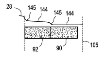
도 19는 에어 베어링의 선단 에지로 내측 다공성 본체의 중심으로부터 연장하는 유리시트의 에지뷰를 묘사하며 에어 베어링에 걸쳐 유리시트의 형상을 더 자세히 나타낸다. 포함된 굴곡이 약 수 마이크론일 때 도 19의 설명은 매우 확대된 것을 유념해야 한다. 보이는 바와 같이, 유리시트는 똑같이 별개의 경계선에 의해 분리된 몇개의 뚜렷한 영역으로 나눠질 수 있으며, 유리시트의 일부를 에어 베어링으로 부여하며 일련의 상대적으로 평평한 장치(144)의 형상은 S 형상의 경계 특성(145)에 의해 분리되고, 정체기의 부상 높이는 내측 다공성 본체(예를 들어 경로(102)에 의해 형성된)의 중심의 방향으로 감소한다.19 depicts an edge view of a glass sheet that extends from the center of the inner porous body to the leading edge of the air bearing and further illustrates the shape of the glass sheet over the air bearing. It should be noted that the description of FIG. 19 is very enlarged when the included curvature is about several microns. As can be seen, the glass sheet can be divided into several distinct areas equally separated by separate boundaries, giving a portion of the glass sheet to the air bearings and the shape of the series of relatively
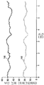
도 20은 유리시트의 두 개의 서로 다른 위치에서 측정된 100mm/s의 진행속도를 가지는 장치(40)의 실시예를 통한 유리시트 진행에 대한 특정된 부상 높이의 그래프이다. 수직인 "Y" 축은 높이를 마이크론으로 나타내며 수평 "X" 축은 시간을 나타낸다. 측정은 주어진 장소에 대해 예정된 빈도(250 sec -1)로 알 수 있다. 따라서, 도 20의 그래프는 유리시트가 에어 베어링에 인접하여 횡단할 때 시간 동안 예정된 위치에서 부상 높이를 알기 위해 사용될 수 있다. 유리 시트는 일반적인 중앙선 위치로부터 +/-75mm의 첫번째의 측면 대 측면 흔들림을 가진다. 각각의 에어 안정화 나이프는 45도의 아래를 향하는 각도에서 유리시트에 대한 에어를 향했다. 에어 베어링의 내측 다공성 본체부는 0.63 +/- 0.25 CFM의 흐름률로 20 psi 부터 60 psi 의 압력으로 에어가 제공되는 동안, 외측 다공성 본체는 40 에서 85 psi의 압력 및 0.96 +/- 0.35 CFM의 흐름률의 에어로 제공된다. 경로(102)에 의해 형성된 원형의 측정존에 걸친 유리시트의 부상 높이는 +/-2.5㎛ 이하의 변동성을 가지며 일반적으로 28㎛였다. 도 20의 커브 146는 약 210도의 위치에서 내측 다공성 본체 부재(90)의 외주의 유리시트의 부상 높이를 보여주며, 유리시트 진행은 100 mm/s의 속도이며, 도 20의 커브 148은 내측 다공성 본체(즉, 경로(102)의 중앙)의 중앙의 부상 높이를 나타낸다. 유리시트의 진행방향에 대한 커브는 특히 유리시트의 두 위치 - 외측 다공성 본체부의 외주의 측정 위치와 다공성 본체의 중심의 측정위치에서의 부상 높이의 안정성을 보여주기 위해 특히 나타난다. 일반적인 부상 높이는 두 영역들 사이에서 차이나며, 외측 다공성 본체 위치는 다공성 본체의 둠싱보다 매우 더 크며 두 위치의 부상 높이는 매우 안정적이며 약 2.5 마이크론 이하의 변동성을 보인다.FIG. 20 is a graph of the specified lift height for glass sheet progression through an embodiment of the
당업자에게 본 발명의 본질 및 사상에 벗어남 없이 다양한 수정 및 변동이 본 발명에 이루어질 수 있음은 명백할 것이다. 따라서 본 발명의 수정 및 변형을 포함하는 본 발명은 청구항 및 그 등가물의 범위 내에 나타나게 제공되도록 의도된다.It will be apparent to those skilled in the art that various modifications and variations can be made in the present invention without departing from the spirit and spirit of the invention. Accordingly, it is intended that the present invention, including modifications and variations of this invention, come within the scope of the claims and their equivalents.
6: 유리 제조 시스템 8: 배취 재료
10: 용융소 12: 용융유리재료
14: 정제소 16: 교반장치
18: 수용용기 20: 성형체
24: 성형면 26: 유리리본
30: 용해정제연결튜브 32: 정제교반장치연결튜브
34: 교반장치수용용기튜브 36: 다운커머튜브
38: 성형체 유입구 40: 장치
42: 프레임 44: 에어 베어링
48: 컨베이어 49: 클램핑 메커니즘
50: 진행 54: 에지 안내 장치
56a, 56b: 안내 암 58: 안내 슬롯
62: 에지 제한 장치 64: 배치 롤러6: glass manufacturing system 8: batch materials
10: molten iron 12: molten glass material
14: refinery 16: stirring device
18: container 20: molded body
24: forming surface 26: glass ribbon
30: dissolution tablet connection tube 32: tablet stirring device connection tube
34: agitator vessel container tube 36: downcomer tube
38: molded inlet 40: apparatus
42: frame 44: air bearing
48: conveyor 49: clamping mechanism
50: progress 54: edge guide device
56a, 56b: guide arm 58: guide slot
62: edge limiter 64: placement roller
Claims (10)
유리시트의 진행방향과 관련하여 에어 베어링의 업스트림에 위치된 다수의 에어 안정화 나이프들; 및
상기 유리시트의 적어도 하나의 속성을 측정하기 위한 측정장치를 구비하며,
상기 내측 다공성 본체부는 상기 에어 베어링의 두께를 통해 뻗어있는 중앙 통로를 형성하고, 상기 측정장치는 상기 에어 베어링의 중앙 통로에 정렬된 유리시트가 장치를 지날 때 유리시트 특성화 장치.An air bearing having an annular inner porous body portion and an outer porous body portion disposed on the inner porous body portion; And
A plurality of air stabilizing knives positioned upstream of the air bearing in relation to the direction of travel of the glass sheet; And
It is provided with a measuring device for measuring at least one property of the glass sheet,
Wherein said inner porous body portion defines a central passage extending through the thickness of said air bearing, said measuring device being a glass sheet characterizing apparatus as a glass sheet aligned with said central passage of said air bearing passes through the apparatus.
상기 내측 다공성 본체부는 표면에서 원형 홈부를 구비하며, 다수의 방사형 홈부는 환형 홈부를 교차하고, 상기 환형홈부는 진공 포트를 구비하는 것을 특징으로 하는 유리시트 특성화 장치.The method according to claim 1,
Wherein said inner porous body portion has a circular groove portion on its surface, a plurality of radial groove portions intersect the annular groove portion, and said annular groove portion has a vacuum port.
상기 외측 다공성 본체부는 다수의 연속적인 홈부를 구비하며, 각각의 연속적인 홈부는 다수의 진공 포트를 구비하는 것을 특징으로 하는 유리시트 특성화 장치.The method according to claim 1,
Wherein said outer porous body portion has a plurality of continuous grooves, each successive groove portion having a plurality of vacuum ports.
상기 측정장치는 상기 중앙 통로를 통해 적어도 하나의 속성을 측정하도록 형성된 것을 특징으로 하는 유리시트 특성화 장치.The method according to claim 1,
And the measuring device is configured to measure at least one property through the central passage.
상기 다수의 에어 안정화 나이프들은 아치형상인 것을 특징으로 하는 유리시트 특성화 장치.The method according to claim 1,
And said plurality of air stabilizing knives are arcuate.
유리시트가 상기 제1 방향으로 움직일 때 적어도 두 개의 에어 안정화 나이프들 사이의 유리시트를 지나게 함으로써 제1 방향과 직교인 제2 방향의 유리시트 움직임을 완화하는 단계;
상기 유리시트를 원형의 에어 베어링에 연결시키는 단계;
상기 유리시트가 상기 제1 방향으로 움직일때 상기 유리시트의 적어도 하나의 속성을 측정하는 단계를 포함하며,
상기 유리시트는 한 쌍의 마주보는 주요면들, 밑면 에지 및 상기 제1 방향과 관련된 선단 에지를 구비하고, 상기 원형의 에어 베어링은 내측 다공성 본체부와 상기 내측 다공성 본체부에 위치된 외측 다공성 본체부를 구비하며, 상기 내측 다공성 본체부는 관통하는 중앙 통로를 형성하는 이동 유리시트 특성화 방법.Moving the glass sheet in a first direction along a predetermined path;
Mitigating glass sheet movement in a second direction orthogonal to the first direction by passing the glass sheet between at least two air stabilizing knives when the glass sheet moves in the first direction;
Connecting the glass sheet to a circular air bearing;
Measuring at least one property of the glass sheet when the glass sheet moves in the first direction,
The glass sheet has a pair of opposing major surfaces, a bottom edge and a leading edge associated with the first direction, wherein the circular air bearing has an inner porous body portion and an outer porous body positioned on the inner porous body portion. And a portion, wherein the inner porous body portion forms a central passage therethrough.
상기 유리시트를 평탄화하는 단계를 더 포함하는 것을 특징으로 하는 이동 유리시트 특성화 방법.The method of claim 6,
Moving glass sheet characterization method comprising the step of flattening the glass sheet.
상기 유리시트는 수직으로 매달린 것을 특징으로 하는 이동 유리시트 특성화 방법.The method of claim 6,
Moving glass sheet characterization method characterized in that the glass sheet is suspended vertically.
상기 에어 베어링의 높이는 상기 유리시트의 높이의 1/2 이하인 것을 특징으로 하는 이동 유리시트 특성화 방법.The method of claim 6,
The height of the air bearing is moving glass sheet characterization method, characterized in that less than 1/2 of the height of the glass sheet.
상기 에어 베어링은 상기 유리시트가 측정될 때 상기 유리시트의 상부 절반이 상기 에어 베어링에 인접하지 않도록 배치된 것을 특징으로 하는 이동 유리시트 특성화 방법.
The method of claim 6,
And the air bearing is arranged such that the upper half of the glass sheet is not adjacent to the air bearing when the glass sheet is measured.
Applications Claiming Priority (2)
| Application Number | Priority Date | Filing Date | Title |
|---|---|---|---|
| US201161526860P | 2011-08-24 | 2011-08-24 | |
| US61/526,860 | 2011-08-24 |
Publications (1)
| Publication Number | Publication Date |
|---|---|
| KR20130022390A true KR20130022390A (en) | 2013-03-06 |
Family
ID=47761302
Family Applications (1)
| Application Number | Title | Priority Date | Filing Date |
|---|---|---|---|
| KR1020120093215A KR20130022390A (en) | 2011-08-24 | 2012-08-24 | Apparatus and method for characterizing glass sheets |
Country Status (5)
| Country | Link |
|---|---|
| US (2) | US8773656B2 (en) |
| JP (2) | JP5936952B2 (en) |
| KR (1) | KR20130022390A (en) |
| CN (2) | CN102951838B (en) |
| TW (1) | TWI530669B (en) |
Families Citing this family (11)
| Publication number | Priority date | Publication date | Assignee | Title |
|---|---|---|---|---|
| US8773656B2 (en) * | 2011-08-24 | 2014-07-08 | Corning Incorporated | Apparatus and method for characterizing glass sheets |
| DK3080548T3 (en) * | 2013-12-09 | 2020-05-25 | Hatch Pty Ltd | Measuring apparatus and method therefor |
| JP6484482B2 (en) * | 2014-06-30 | 2019-03-13 | AvanStrate株式会社 | Glass plate manufacturing method and glass plate manufacturing apparatus |
| US10613007B2 (en) | 2015-03-13 | 2020-04-07 | Corning Incorporated | Edge strength testing methods and apparatuses |
| WO2016163373A1 (en) * | 2015-04-10 | 2016-10-13 | 旭硝子株式会社 | Glass plate |
| TWI762083B (en) * | 2015-09-17 | 2022-04-21 | 美商康寧公司 | Methods of characterizing ion-exchanged chemically strengthened glasses containing lithium |
| SG11201907719RA (en) * | 2017-02-24 | 2019-09-27 | Corning Inc | Dome or bowl shaped glass and method of fabricating dome or bowl shaped glass |
| WO2019168951A1 (en) * | 2018-02-28 | 2019-09-06 | Corning Incorporated | Non-contact glass substrate guiding apparatus and method |
| WO2019199933A1 (en) * | 2018-04-12 | 2019-10-17 | Corning Incorporated | Apparatus and method for engaging a moving glass ribbon |
| JP2022501297A (en) * | 2018-09-19 | 2022-01-06 | コーニング インコーポレイテッド | Equipment and methods for processing glass sheets |
| CN118392103B (en) * | 2024-06-26 | 2024-08-30 | 阳信华阳集团有限公司 | On-line detection leather thickness equipment |
Family Cites Families (24)
| Publication number | Priority date | Publication date | Assignee | Title |
|---|---|---|---|---|
| US3062520A (en) * | 1957-08-19 | 1962-11-06 | Sunbeam Corp | Conveying apparatus for sheet material employing fluid support means |
| DE1908109B2 (en) * | 1969-02-19 | 1971-08-05 | Deutsche Tafelglas AG Detag, 3510Furth | Guide device for vertically transported sheet-like goods, especially for the production of double or multiple panes of glass |
| US4824248A (en) * | 1987-12-21 | 1989-04-25 | Environmental Research Institute Of Michigan | Stabilized sensor device |
| DE4343810C1 (en) * | 1993-12-22 | 1995-04-20 | Roland Man Druckmasch | Photoelectric measuring head |
| US5654799A (en) * | 1995-05-05 | 1997-08-05 | Measurex Corporation | Method and apparatus for measuring and controlling the surface characteristics of sheet materials such as paper |
| US5642192A (en) * | 1995-06-12 | 1997-06-24 | Measurex Corporation | Dual spectrometer color sensor |
| US5642189A (en) * | 1995-06-12 | 1997-06-24 | Measurex Corporation | Color sensor simulating standard source illuminant |
| JPH1035882A (en) * | 1996-07-23 | 1998-02-10 | Nippon Electric Glass Co Ltd | Device for continuously carrying plate material to working position without generating contact therewith |
| US6359686B1 (en) * | 1999-06-29 | 2002-03-19 | Corning Incorporated | Inspection system for sheet material |
| US6588118B2 (en) * | 2001-10-10 | 2003-07-08 | Abb Inc. | Non-contact sheet sensing system and related method |
| JP3611563B2 (en) * | 2003-01-09 | 2005-01-19 | 川重プラント株式会社 | Vertical processing line for plate material |
| US7077019B2 (en) * | 2003-08-08 | 2006-07-18 | Photon Dynamics, Inc. | High precision gas bearing split-axis stage for transport and constraint of large flat flexible media during processing |
| US20060042314A1 (en) * | 2004-08-27 | 2006-03-02 | Abbott John S Iii | Noncontact glass sheet stabilization device used in fusion forming of a glass sheet |
| WO2006052919A1 (en) * | 2004-11-08 | 2006-05-18 | New Way Machine Components, Inc. | Non-contact porous air bearing and glass flattening device |
| US7516628B2 (en) * | 2005-01-11 | 2009-04-14 | Corning Incorporated | On-line thickness gauge and method for measuring the thickness of a moving glass substrate |
| US7567344B2 (en) * | 2006-05-12 | 2009-07-28 | Corning Incorporated | Apparatus and method for characterizing defects in a transparent substrate |
| US20080022811A1 (en) * | 2006-06-30 | 2008-01-31 | Murray Kathan | Power tong having cam followers with sliding contact surfaces |
| US7714996B2 (en) * | 2007-01-23 | 2010-05-11 | 3i Systems Corporation | Automatic inspection system for flat panel substrate |
| EP2123581A4 (en) * | 2007-03-07 | 2013-12-25 | Ulvac Inc | Vacuum device and method of conveying substrate |
| US7607647B2 (en) * | 2007-03-20 | 2009-10-27 | Kla-Tencor Technologies Corporation | Stabilizing a substrate using a vacuum preload air bearing chuck |
| KR101587176B1 (en) | 2007-04-18 | 2016-01-20 | 마이크로닉 마이데이타 에이비 | Method and apparatus for mura detection and metrology |
| CA2884632C (en) * | 2007-08-31 | 2016-10-25 | Abb Ltd. | Web thickness measurement device |
| KR101634825B1 (en) * | 2008-06-09 | 2016-06-29 | 케이엘에이-텐코어 코오포레이션 | Referenced inspection device |
| US8773656B2 (en) | 2011-08-24 | 2014-07-08 | Corning Incorporated | Apparatus and method for characterizing glass sheets |
-
2012
- 2012-08-22 US US13/591,994 patent/US8773656B2/en not_active Expired - Fee Related
- 2012-08-23 CN CN201210302755.8A patent/CN102951838B/en not_active Expired - Fee Related
- 2012-08-23 JP JP2012183870A patent/JP5936952B2/en not_active Expired - Fee Related
- 2012-08-23 CN CN2012204215403U patent/CN202808599U/en not_active Withdrawn - After Issue
- 2012-08-24 KR KR1020120093215A patent/KR20130022390A/en not_active Application Discontinuation
- 2012-08-24 TW TW101130867A patent/TWI530669B/en active
-
2014
- 2014-05-15 US US14/278,599 patent/US9090412B2/en not_active Expired - Fee Related
-
2016
- 2016-05-11 JP JP2016095145A patent/JP5974199B1/en not_active Expired - Fee Related
Also Published As
| Publication number | Publication date |
|---|---|
| TW201321715A (en) | 2013-06-01 |
| JP5974199B1 (en) | 2016-08-23 |
| US20130067956A1 (en) | 2013-03-21 |
| US8773656B2 (en) | 2014-07-08 |
| CN102951838A (en) | 2013-03-06 |
| CN202808599U (en) | 2013-03-20 |
| CN102951838B (en) | 2015-03-25 |
| TWI530669B (en) | 2016-04-21 |
| US20140248096A1 (en) | 2014-09-04 |
| JP2013043829A (en) | 2013-03-04 |
| US9090412B2 (en) | 2015-07-28 |
| JP5936952B2 (en) | 2016-06-22 |
| JP2016179936A (en) | 2016-10-13 |
Similar Documents
| Publication | Publication Date | Title |
|---|---|---|
| KR20130022390A (en) | Apparatus and method for characterizing glass sheets | |
| US20090092472A1 (en) | Apparatus and system for handling a glass sheet | |
| JP5092627B2 (en) | Substrate transfer device and substrate inspection device | |
| TWI682907B (en) | Continuous processing of flexible glass ribbon with reduced mechanical stress | |
| WO2017151368A1 (en) | Method and apparatus for transport of a glass substrate | |
| CN104098263A (en) | Apparatus and method for conveying a glass tube strand or glass rod strand having a cross-section different from a circular cross-section and use thereof | |
| JP7265553B2 (en) | Thin glass ribbon processing system and method | |
| KR101338028B1 (en) | Measurement apparatus and measurement system for inspection of a surface of a substrate | |
| KR101014121B1 (en) | Measuring device and measuring method for inspecting the surface of a substrate | |
| JP7300456B2 (en) | Thin glass ribbon processing system and method | |
| JP5273652B2 (en) | Processing apparatus, processing method, defect correction apparatus, defect correction method, and pattern substrate manufacturing method. | |
| CN206665691U (en) | A kind of conveyer for glass substrate | |
| US20200199004A1 (en) | Enclosures for glass forming apparatuses | |
| WO2024049727A1 (en) | Methods and apparatus for manufacturing a ribbon | |
| US20240025791A1 (en) | Systems and methods for processing thin glass ribbons | |
| JP2006173172A (en) | Substrate supporting apparatus | |
| TW201936470A (en) | Non-contact glass substrate guiding apparatus and method | |
| US20190152824A1 (en) | Molten material stirring system and method for stirring the material | |
| WO2024097124A1 (en) | Methods and apparatus for manufacturing a glass ribbon | |
| TW202023968A (en) | Molten material stirring system and method for stirring the material | |
| JP2002228783A (en) | Inclination adjusting device and flatness measuring device for plate body using the same |
Legal Events
| Date | Code | Title | Description |
|---|---|---|---|
| WITN | Application deemed withdrawn, e.g. because no request for examination was filed or no examination fee was paid |