JP5936952B2 - Apparatus and method for characterizing sheet glass - Google Patents
Apparatus and method for characterizing sheet glass Download PDFInfo
- Publication number
- JP5936952B2 JP5936952B2 JP2012183870A JP2012183870A JP5936952B2 JP 5936952 B2 JP5936952 B2 JP 5936952B2 JP 2012183870 A JP2012183870 A JP 2012183870A JP 2012183870 A JP2012183870 A JP 2012183870A JP 5936952 B2 JP5936952 B2 JP 5936952B2
- Authority
- JP
- Japan
- Prior art keywords
- porous body
- air
- glass
- body portion
- glass sheet
- Prior art date
- Legal status (The legal status is an assumption and is not a legal conclusion. Google has not performed a legal analysis and makes no representation as to the accuracy of the status listed.)
- Expired - Fee Related
Links
Images


Classifications
-
- B—PERFORMING OPERATIONS; TRANSPORTING
- B65—CONVEYING; PACKING; STORING; HANDLING THIN OR FILAMENTARY MATERIAL
- B65G—TRANSPORT OR STORAGE DEVICES, e.g. CONVEYORS FOR LOADING OR TIPPING, SHOP CONVEYOR SYSTEMS OR PNEUMATIC TUBE CONVEYORS
- B65G51/00—Conveying articles through pipes or tubes by fluid flow or pressure; Conveying articles over a flat surface, e.g. the base of a trough, by jets located in the surface
- B65G51/02—Directly conveying the articles, e.g. slips, sheets, stockings, containers or workpieces, by flowing gases
- B65G51/03—Directly conveying the articles, e.g. slips, sheets, stockings, containers or workpieces, by flowing gases over a flat surface or in troughs
-
- G—PHYSICS
- G01—MEASURING; TESTING
- G01N—INVESTIGATING OR ANALYSING MATERIALS BY DETERMINING THEIR CHEMICAL OR PHYSICAL PROPERTIES
- G01N33/00—Investigating or analysing materials by specific methods not covered by groups G01N1/00 - G01N31/00
- G01N33/38—Concrete; ceramics; glass; bricks
-
- C—CHEMISTRY; METALLURGY
- C03—GLASS; MINERAL OR SLAG WOOL
- C03B—MANUFACTURE, SHAPING, OR SUPPLEMENTARY PROCESSES
- C03B17/00—Forming molten glass by flowing-out, pushing-out, extruding or drawing downwardly or laterally from forming slits or by overflowing over lips
-
- C—CHEMISTRY; METALLURGY
- C03—GLASS; MINERAL OR SLAG WOOL
- C03B—MANUFACTURE, SHAPING, OR SUPPLEMENTARY PROCESSES
- C03B35/00—Transporting of glass products during their manufacture, e.g. hot glass lenses, prisms
- C03B35/14—Transporting hot glass sheets or ribbons, e.g. by heat-resistant conveyor belts or bands
- C03B35/20—Transporting hot glass sheets or ribbons, e.g. by heat-resistant conveyor belts or bands by gripping tongs or supporting frames
-
- G—PHYSICS
- G01—MEASURING; TESTING
- G01N—INVESTIGATING OR ANALYSING MATERIALS BY DETERMINING THEIR CHEMICAL OR PHYSICAL PROPERTIES
- G01N33/00—Investigating or analysing materials by specific methods not covered by groups G01N1/00 - G01N31/00
- G01N33/38—Concrete; ceramics; glass; bricks
- G01N33/386—Glass
Description
本発明は、板ガラスをキャラクタリゼーションするための装置および方法に関し、特に、板ガラスが移動している間に板ガラスの1つまたは複数の選択した特性を測定するようになっている装置に関する。 The present invention relates to an apparatus and method for characterizing a glazing, and more particularly to an apparatus adapted to measure one or more selected properties of a glazing while the glazing is moving.
本発明は、トポグラフィー検査(例えば、ナノトポグラフィー、すなわちナノメートルスケールのトポグラフィー)などの高解像度のオンライン測定を可能にするために所定の経路に沿って搬送される板ガラスの動きおよび姿勢を制御することに関する。薄板ガラスの正確なオンライン測定、特に、ナノメートルスケールの特徴の測定は、板ガラスを一定の面において一定の向きで常に提示すること、ならびにガラスの大半の振動および揺れを排除することに大きく依存している。厚み、うねりおよびすじの高精度測定のような課題は、再生可能な、高公差のマテリアルハンドリングによってガラス表面を測定ゲージに提示することに大きく依存している。 The present invention allows for the movement and attitude of a glass sheet conveyed along a predetermined path to allow high resolution online measurements such as topography inspection (eg, nanotopography, ie, nanometer scale topography). Related to controlling. Accurate on-line measurement of thin glass, especially the measurement of nanometer-scale features, relies heavily on always presenting the glass in a certain orientation in a certain plane and eliminating most of the vibration and shaking of the glass. ing. Issues such as high-precision measurement of thickness, waviness and streaks rely heavily on presenting the glass surface to the measurement gauge with reproducible, high-tolerance material handling.
オンラインのすじおよび縞検査などのオンラインのプロセス制御および品質測定には、ガラスを低品質領域において単に把持している間に実施された場合、繰り返し性の不足が生じる。材料提示の課題の大部分は、オーバーヘッドコンベヤ上の搬送台から吊されている間、生産ラインを移動するガラスの板を保持することである。この制限によって、プロセスラインの別々の検査部において完全にオフラインで、またはその性能(例えば解像度)が不十分な、粗い従来のオンラインマテリアルハンドリングに適合する測定技術のいずれかで、測定を実施することを余儀なくされる。 On-line process control and quality measurement, such as on-line streak and fringe inspection, results in a lack of repeatability when performed while simply holding the glass in a low quality area. A major part of the material presentation challenge is to hold the glass plate moving through the production line while suspended from the carriage on the overhead conveyor. Due to this limitation, the measurement should be carried out either in a separate inspection section of the process line, either offline, or with a measurement technique compatible with rough conventional online material handling, whose performance (eg resolution) is insufficient. Will be forced.
シリコンウェハまたは紙およびプラスチックウェブなどの他の業界では、高解像度計測法はオンラインで実施されるが、これらの場合においては、ウェハまたはローラと同様、ほとんどのウェブと同様、製品は支持板に直に接している。ディスプレイ用途に適した板ガラスの大きさおよびそれに対して接触が禁止されていることによって、ハンドリングに困難な課題が生じる。 In other industries, such as silicon wafers or paper and plastic webs, high-resolution metrology is performed online, but in these cases, as with most webs, as with wafers or rollers, the product is applied directly to the support plate. Is in contact with Due to the size of the glass sheet suitable for display applications and the prohibition of contact with it, difficult problems arise in handling.
一般に厚さ1mm以下の薄板ガラスの測定では、ガラスの特定の特性を測定する際、特に、ガラスが大型(例えば、約4m2超)の場合、困難を生じさせる一定量の湾曲または反りを呈する可能性がある。この欠点を克服するため、まずガラスを平坦にしなければならない。従来、板ガラスの平坦化および安定化には、インライン経路から板を取り出し、板ガラスを精密石定盤に搬送し、その後、個々の板ガラスを吸引台まで吸引し、所望の測定を実施し、板ガラスを取り外し、その後、別の板ガラスにおいて同じ操作を実施することを含む。そのようなまとまりのない手法によって製造工程にかなりの時間と費用がかかる。板ガラスが製造ラインに沿って搬送されている間に板ガラスを測定する必要がある場合、大型薄板ガラスの計測における問題は悪化する。 In general, in the measurement of a thin glass having a thickness of 1 mm or less, a certain amount of bending or warping that causes difficulty is exhibited when measuring specific characteristics of the glass, particularly when the glass is large (eg, greater than about 4 m 2 ). there is a possibility. To overcome this drawback, the glass must first be flattened. Conventionally, flattening and stabilization of plate glass is performed by taking out the plate from the in-line path, transporting the plate glass to a precision stone surface plate, and then sucking each plate glass to the suction table, performing the desired measurement, Removing and then performing the same operation on another glass sheet. Such a coherent approach adds considerable time and expense to the manufacturing process. If the plate glass needs to be measured while the plate glass is being transported along the production line, the problem in measuring large thin glass is exacerbated.
いくつかの製造工程では、板ガラスは、オーバーヘッドコンベヤの可動部材に板ガラスを固定することによって1つの位置から別の位置まで運搬されうる。最初に板ガラスを取り外して板ガラスを静止物体として測定台の上に配置することなく、板ガラスが移動している間に1つまたは複数の上述のキャラクタリゼーションを達成することができれば有利であろう。 In some manufacturing processes, the glass sheet can be transported from one position to another by securing the glass sheet to a movable member of an overhead conveyor. It would be advantageous if one or more of the above-described characterizations could be achieved while the plate glass was moving without first removing the plate glass and placing the plate glass as a stationary object on the measurement table.
この目的のため、液晶ディスプレイデバイスにおける使用に適した板ガラスのような移動する板ガラスを、コンベヤ搬送台になお保持している間に板ガラスを拘束することによって精密計測を実施するための装置を開示する。装置のマテリアルハンドリング機能には、装置に入る板ガラスを非接触とするが、測定が実施されうる箇所まで拘束力が段階的に増加するような、直線式に配置された、エアナイフと圧力真空(PV)空気軸受とを含む。その後、板が装置から解放されるまで拘束力の段階的な減少が生じる。コンベヤ搬送台近辺の挟持点において板を拘束することなく板の動きを制限するため、この段階的な力の技法が板ガラスの移動する方向に、また、板の高さに沿って垂直上方に適用される。 To this end, an apparatus is disclosed for performing precision measurements by restraining a glass sheet while still holding a moving glass sheet, such as a glass sheet suitable for use in a liquid crystal display device, on a conveyor carriage. . The material handling function of the device is a non-contact plate glass entering the device, but with a linear arrangement of air knives and pressure vacuum (PV) so that the binding force increases stepwise to where the measurement can be performed. ) Including air bearings. Thereafter, a gradual decrease in restraining force occurs until the plate is released from the device. This stepwise force technique is applied in the direction of movement of the glass and vertically upward along the height of the plate to limit the movement of the plate without constraining the plate at the clamping point near the conveyor carriage. Is done.
したがって、内部多孔質体部分の表面にある環状溝と、環状の溝に交差する複数の半径方向の溝とを含む環状の内部多孔質体部分であって、空気軸受の厚さ全体に延びる中心通路を画定する内部多孔質体部分と、内部多孔質体部分の周りに配置された外部多孔質体部分であって、外部多孔質体部分の表面に複数の連続的な溝を含む外部多孔質体部分と、を含み、外部多孔質体部分の各連続的な溝が複数の真空ポートを含む空気軸受を開示する。内部多孔質体部分の環状の溝および内部多孔質体部分の半径方向の溝は内部多孔質体部分の表面を複数の下位表面に分割し、複数の下位表面の下位表面は真空ポートを含む。好ましくは、複数の下位表面の各下位表面は真空ポートを含む。 Thus, an annular inner porous body portion comprising an annular groove on the surface of the inner porous body portion and a plurality of radial grooves intersecting the annular groove, the center extending through the entire thickness of the air bearing An inner porous body portion defining a passage, and an outer porous body portion disposed around the inner porous body portion, wherein the outer porous body includes a plurality of continuous grooves on the surface of the outer porous body portion And an air bearing wherein each continuous groove in the outer porous body portion includes a plurality of vacuum ports. The annular groove of the inner porous body portion and the radial groove of the inner porous body portion divide the surface of the inner porous body portion into a plurality of lower surfaces, and the lower surfaces of the plurality of lower surfaces include a vacuum port. Preferably, each lower surface of the plurality of lower surfaces includes a vacuum port.
外部多孔質体部分は、好ましくは、弓形の外周を含む。好ましくは、外部多孔質体部分は、空気軸受が、環状の内部多孔質体部分と、内部多孔質体部分の周りに配置され、かつ内部多孔質体部分と同軸である環状の外部多孔質体部分とを含むような環状の外周を含む。いくつかの実施形態では、空気軸受は複数の内部多孔質体部分を含む。例えば、複数の内部多孔質体部分は水平軸線に沿って整列されてもよい。 The outer porous body portion preferably includes an arcuate perimeter. Preferably, the outer porous body portion has an annular outer porous body in which an air bearing is arranged around the inner porous body portion and the inner porous body portion and is coaxial with the inner porous body portion. And an annular outer periphery that includes a portion. In some embodiments, the air bearing includes a plurality of internal porous body portions. For example, the plurality of internal porous body portions may be aligned along a horizontal axis.
別の実施形態では、板ガラスが装置を通過して移動する際に板ガラスをキャラクタリゼーションするための装置を開示する。この装置は、環状の内部多孔質体部分と、内部多孔質体部分の周りに配置された外部多孔質体部分であって、空気軸受の厚さ全体に延びる中心通路を画定する内部多孔質体部分と、を含む空気軸受と、板ガラスの移動方向を基準として空気軸受の上流側に配置されている複数の安定化エアナイフと、板ガラスの少なくとも1つの特性を測定するための測定デバイスであって、空気軸受の中心通路と並んだ測定デバイスと、を含む。内部多孔質体部分はその表面にある環状の溝を含む。内部多孔質体部分は環状の溝に交差する複数の半径方向の溝をさらに含んでもよい。内部多孔質体部分の表面は真空ポートを含む。内部多孔質体部分が環状溝と複数の半径方向の溝とを含む場合、環状溝および半径方向の溝は内部多孔質体部分に複数の下位表面を画定する。好ましくは、各下位表面は真空ポートを含む。 In another embodiment, an apparatus is disclosed for characterizing a glass sheet as it moves through the apparatus. The apparatus includes an annular inner porous body portion and an outer porous body portion disposed around the inner porous body portion, the inner porous body defining a central passage extending through the entire thickness of the air bearing. An air bearing including a portion, a plurality of stabilizing air knives disposed upstream of the air bearing with respect to a moving direction of the glass sheet, and a measuring device for measuring at least one characteristic of the glass sheet, A measuring device aligned with the central passage of the air bearing. The inner porous body portion includes an annular groove on its surface. The inner porous body portion may further include a plurality of radial grooves that intersect the annular groove. The surface of the inner porous body portion includes a vacuum port. Where the inner porous body portion includes an annular groove and a plurality of radial grooves, the annular groove and the radial groove define a plurality of subsurfaces in the inner porous body portion. Preferably, each lower surface includes a vacuum port.
外部多孔質体部分は、複数の連続的な(すなわち閉じた)溝を含む。各連続的な溝は複数の真空ポートを含む。例えば、各連続的な溝は、環形、楕円形、長円形、または任意の他の閉じた連続的な形とすることができる。好ましくは、外部多孔質体部分の外周は弓形である。例えば、外部多孔質体部分の外周は環状であってもよい。いくつかの実施形態では、空気軸受は複数の内部多孔質体部分を含んでもよい。 The outer porous body portion includes a plurality of continuous (ie, closed) grooves. Each continuous groove includes a plurality of vacuum ports. For example, each continuous groove can be annular, elliptical, oval, or any other closed continuous shape. Preferably, the outer periphery of the outer porous body portion is arcuate. For example, the outer periphery of the outer porous body portion may be annular. In some embodiments, the air bearing may include a plurality of internal porous body portions.
測定デバイスは、好ましくは、内部多孔質体部分によって画定された通路を通じて少なくとも1つの特性を測定する。 The measuring device preferably measures at least one characteristic through a passage defined by the internal porous body portion.
安定化エアナイフは安定化エアナイフからの空気の流れが下方に角度をなすように配向されている。つまり、安定化エアナイフからの空気の流れは、好ましくは、空気の流れが板ガラスとともに鋭角を形成するように水平面に対して下方に案内される。例えば、空気の流れの方向は板ガラスに対して約15度〜約75度の範囲の角度を形成してもよい。好ましくは、安定化エアナイフは弓形の形状である。 The stabilized air knife is oriented so that the air flow from the stabilized air knife is angled downward. That is, the air flow from the stabilizing air knife is preferably guided downward relative to the horizontal plane so that the air flow forms an acute angle with the glass sheet. For example, the direction of air flow may form an angle in the range of about 15 degrees to about 75 degrees with respect to the glass sheet. Preferably, the stabilizing air knife has an arcuate shape.
本実施形態による装置は、空気軸受の下流側に配置された、板ガラスを空気軸受から離れる方向に押すための位置決めエアナイフをさらに含んでもよい。 The apparatus according to the present embodiment may further include a positioning air knife arranged on the downstream side of the air bearing for pushing the glass sheet away from the air bearing.
さらに別の実施形態では、移動する板ガラスをキャラクタリゼーションする方法を説明する。この方法は、所定の経路に沿って第1の方向に板ガラスを移動するステップであって、板ガラスが、一対の対向する主表面と、底縁と、第1の方向に対する前縁とを含む、ステップと、板ガラスが第1の方向に移動する際に、少なくとも2つの安定化エアナイフ間に板ガラスを通すことにより、第1の方向に垂直な第2の方向における板ガラスの動きを減衰するステップと、板ガラスを環状の空気軸受と係合させるステップであって、環状の空気軸受が、内部多孔質体部分と、内部多孔質体部分の周りに配置された外部多孔質体部分とを含み、内部多孔質体部分がその中を通る中心通路を画定する、ステップと、板ガラスが第1の方向に移動する際に板ガラスの少なくとも1つの特性を測定するステップと、を含む。方法は、「V字」形のスロットを間に形成するように配置されたガイドアームを含む縁案内デバイスによって板ガラスの底縁を案内するステップをさらに含んでもよい。 In yet another embodiment, a method for characterizing a moving glass sheet is described. The method includes moving the glazing in a first direction along a predetermined path, the glazing including a pair of opposing major surfaces, a bottom edge, and a leading edge relative to the first direction. Attenuating movement of the glass sheet in a second direction perpendicular to the first direction by passing the glass sheet between at least two stabilizing air knives as the glass sheet moves in the first direction; Engaging the glass sheet with an annular air bearing, the annular air bearing including an inner porous body portion and an outer porous body portion disposed around the inner porous body portion, The body portion defining a central passage therethrough and measuring at least one characteristic of the glass sheet as the glass sheet moves in the first direction. The method may further comprise the step of guiding the bottom edge of the glazing by an edge guiding device comprising a guide arm arranged to form a “V” shaped slot therebetween.
空気軸受の高さ、特に外部多孔質体部分の高さは板ガラスの高さの2分の1未満である。空気軸受は、板ガラスを測定する際、板ガラスの上2分の1が好ましくは空気軸受に隣接しないように配置される。空気軸受は、好ましくは、内部多孔質体部分からの所定の距離+/−15μm内に板ガラスを維持することが可能である。 The height of the air bearing, particularly the height of the outer porous body portion, is less than half the height of the plate glass. The air bearing is arranged so that when the plate glass is measured, the upper half of the plate glass is preferably not adjacent to the air bearing. The air bearing is preferably capable of maintaining the glass sheet within a predetermined distance +/− 15 μm from the inner porous body portion.
第1の内部多孔質体部分はその表面にある環状の溝を含む。内部多孔質体部分は、好ましくは、また、内部多孔質体部分の表面にある複数の半径方向の溝を含む。複数の半径方向の溝は環状の溝に交差している。 The first internal porous body portion includes an annular groove on the surface thereof. The inner porous body portion preferably also includes a plurality of radial grooves in the surface of the inner porous body portion. The plurality of radial grooves intersect the annular groove.
空気軸受の外部多孔質体部分は、好ましくは、複数の同心の溝を含む。複数の同心の溝の各溝は複数の真空ポートを含む。 The outer porous body portion of the air bearing preferably includes a plurality of concentric grooves. Each groove of the plurality of concentric grooves includes a plurality of vacuum ports.
さらに別の実施形態では、板ガラスを製造する方法を説明する。この方法は、溶融ガラスを形成するために融解炉においてバッチ材料を加熱するステップと、ガラスリボンを生成するために成形主要部の収束成形面上に溶融ガラスを流すステップと、ガラスリボンから板ガラスを切断するステップと、コンベヤから垂直方向に板ガラスを吊すステップであって、コンベヤは所定の経路に沿う第1の方向に板ガラスを移動するステップと、板ガラスが第1の方向に移動する際に少なくとも2つの安定化エアナイフ間に板ガラスを通すことにより第1の方向に垂直な第2の方向における板ガラスの動きを減衰するステップと、板ガラスを空気軸受と係合するステップであって、空気軸受が環状の内部多孔質体部分と、環状の内部多孔質体部分の周りに配置された外部多孔質体部分とを含み、環状の内部多孔質体部分がその中を通る中心通路を画定する、ステップと、板ガラスが第1の方向に移動する際に、板ガラスの少なくとも1つの特性を中心通路を通じて測定するステップと、を含む。外部多孔質体部分は、好ましくは、環状の外周などの、弓形の外周を含む。 In yet another embodiment, a method for producing a glass sheet is described. The method includes heating a batch material in a melting furnace to form molten glass, flowing molten glass over a converging forming surface of a forming main body to form a glass ribbon, and removing a sheet glass from the glass ribbon. Cutting the sheet glass in a vertical direction from the conveyor, the conveyor moving the sheet glass in a first direction along a predetermined path, and at least two when the sheet glass moves in the first direction. Damping the movement of the glass sheet in a second direction perpendicular to the first direction by passing the glass sheet between two stabilizing air knives; and engaging the glass sheet with the air bearing, wherein the air bearing is annular An inner porous body comprising an inner porous body portion and an outer porous body portion disposed around the annular inner porous body portion Min defining a central passage therethrough, comprising the steps, when the glass sheet is moved in the first direction, and measuring through the central passage at least one characteristic of the glass sheet, a. The outer porous body portion preferably includes an arcuate outer periphery, such as an annular outer periphery.
内部多孔質体部分は、その表面にある環状の溝を含み、好ましくは、環状の溝に交差する複数の半径方向の溝をさらに含む。外部多孔質体部分はその表面にある複数の連続的な溝を含む。 The inner porous body portion includes an annular groove on its surface, and preferably further includes a plurality of radial grooves that intersect the annular groove. The outer porous body portion includes a plurality of continuous grooves on its surface.
方法は、空気軸受の前縁から離れる方向に板ガラスを移動するために第1の位置決めエアナイフを使用するステップをさらに含んでもよい。さらに任意選択的なステップでは、方法は、空気軸受に向かう方向に板ガラスを移動するために第2の位置決めエアナイフを使用するステップをさらに含んでもよい。さらに別の任意選択的なステップでは、方法は、板ガラスを空気軸受の後縁から離すために第3の位置決めエアナイフを使用するステップをさらに含んでもよい。 The method may further include using a first positioning air knife to move the glazing away from the leading edge of the air bearing. In a further optional step, the method may further comprise using a second positioning air knife to move the glazing in a direction toward the air bearing. In yet another optional step, the method may further include using a third positioning air knife to move the glass sheet away from the trailing edge of the air bearing.
少なくとも2つの安定化エアナイフの各安定化エアナイフは空気の流れを下方に案内する。少なくとも2つの安定化エアナイフの安定化エアナイフの先端は、任意選択的に安定化エアナイフの後端に対して下方に勾配していても、傾斜していてもよい。 Each stabilizing air knife of the at least two stabilizing air knives guides the air flow downward. The tips of the stabilizing air knives of the at least two stabilizing air knives may optionally be inclined downward or inclined with respect to the rear end of the stabilizing air knife.
本発明のさらなる特徴および利点が以下の説明において示され、当業者にはこの説明からある程度明らかになるであろう。あるいは以下の詳細な説明、特許請求の範囲、ならびに添付図面を含む本明細書に記載した本発明の実施によって理解するであろう。 Additional features and advantages of the invention will be set forth in the description which follows, and in part will be apparent to those skilled in the art from this description. Alternatively, it will be understood by practice of the invention described herein, including the following detailed description, claims, and accompanying drawings.
前述の概略的な説明および以下の詳細な説明は本発明の実施の形態を示し、特許請求の範囲で規定される発明の本質および性質を理解するための概要または基礎を提供することを意図している。添付の図面は、発明のさらなる理解を提供するために含められ、明細書の一部を構成する。図面は発明のさまざまな実施形態を示し、説明とともに、発明の原理および動作を説明する。 The foregoing general description and the following detailed description set forth embodiments of the invention and are intended to provide an overview or basis for understanding the nature and nature of the invention as defined by the claims. ing. The accompanying drawings are included to provide a further understanding of the invention, and constitute a part of the specification. The drawings illustrate various embodiments of the invention and, together with the description, explain the principles and operations of the invention.
以下の詳細な説明においては、限定ではなく説明のため、具体的詳細を開示する実施形態例を明記して本発明の完全な理解を提供する。しかしながら、本開示から利益を得る当業者には、本発明がここで開示される具体的詳細とは異なる他の実施形態において実施されうることは明らかであろう。さらに、周知のデバイス、方法、および材料についての説明は、本発明の説明を不明瞭にしないよう省略されることがある。最後に、適用できる限り、同じ参照番号は同様の要素を示す。 In the following detailed description, for purposes of explanation and not limitation, example embodiments disclosing specific details are set forth in order to provide a thorough understanding of the present invention. However, it will be apparent to those skilled in the art having the benefit of this disclosure that the present invention may be practiced in other embodiments that depart from the specific details disclosed herein. Further, descriptions of well-known devices, methods and materials may be omitted so as not to obscure the description of the present invention. Finally, wherever applicable, the same reference numbers indicate similar elements.
例えばフュージョンダウンドロー法のようなダウンドロー板ガラス製造法では、ガラスのリボンを形成するのに適した条件の粘度および延伸速度の下で粘性ガラス材料を下方に垂直に延伸することによって板ガラスが形成される。ガラスのリボンはリボンの最上端位置では粘性液体を含み、材料がガラス転移温度範囲を通過するにつれて粘性液体から固体ガラスリボンに遷移する。リボンの流下する底部部分が適切な温度および粘度に達すると、板ガラスがリボンから切断され、工程が継続される。板ガラスは連続的に流下するガラスリボンから切断される。 For example, in a downdraw flat glass manufacturing process such as the fusion downdraw process, a glass sheet is formed by vertically stretching a viscous glass material downward under conditions of viscosity and stretching speed suitable for forming a glass ribbon. The The glass ribbon contains a viscous liquid at the uppermost position of the ribbon and transitions from a viscous liquid to a solid glass ribbon as the material passes the glass transition temperature range. When the bottom part of the ribbon flowing down reaches the proper temperature and viscosity, the glass sheet is cut from the ribbon and the process continues. The sheet glass is cut from a continuously flowing glass ribbon.
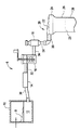
例示的なフュージョンダウンドローガラス製造システム6を図1に示す。図1によれば、バッチ材料8を融解炉10に投入し、加熱して粘性溶融ガラス材料12を形成する。溶融ガラス材料12は、溶融ガラス材料から気泡が除去される精製部14内を搬送され、その後、撹拌装置16において攪拌され、溶融ガラス材料が均質化される。撹拌作業は、溶融ガラス材料の化学的濃度のばらつきをなくし、それによって最終ガラスの物理的特性および光学的特性のばらつきを防止しようとするものである。溶融ガラス材料が攪拌されると、それは受容容器18内を流れ、その後、成形主要部20に流れる。受容容器18は軽微な流れの変動を減衰することによりアキュムレータとして機能する。成形主要部20は、主要部の上部部分に開きょ22を有するセラミック主要部と、成形主要部の底部において結合する一対の収束外部成形面24とを含む。溶融ガラス材料は成形主要部の開きょからあふれ、成形主要部の収束成形面を、溶融ガラス材料の2つの別個の流れとして流下する。収束成形面が結合する位置において溶融ガラス材料の別個の流れが合流し、材料の1つの流れまたはリボン26を形成する。リボンはガラス転移温度範囲を降下するにつれて冷却され、固体ガラスリボンを形成する。この固体ガラスリボンから板ガラス28が切断線29に沿って切断される。
An exemplary fusion downdraw
融解炉10は、融解部と精製部との連結管30を通じて精製部14に連結され、かつ精製部14と流体連通している。精製部14は、精製部と撹拌装置との連結管32を通じて撹拌装置16に連結され、かつ撹拌装置16と流体連通している。撹拌装置16は、攪拌部と受容容器との管34を通じて受容容器18に連結され、かつ受容容器18と流体連通している。受容容器18は、下降管36を通じて成形主要部20および成形主要部入口38に連結され、かつ成形主要部20および成形主要部入口38と流体連通している。融解炉10は、通常、セラミックレンガなどのセラミック材料(例えば、アルミナまたはジルコニア)から形成されるが、溶融ガラス材料の搬送および加工に関わる構成要素は、通常、白金または白金ロジウム合金のような白金合金から形成される、したがって、融解部と精製部との連結管30、精製部14、精製部と撹拌装置との連結管32、撹拌装置16、撹拌装置と受容容器との管34、受容容器18、下降管36および成形主要部入口38は、通常、白金または白金ロジウム合金を含む。
The melting
板ガラスは、ガラスリボン26から取り出された際に垂直に向く板として開始するため、板ガラスが、成形工程の下流側における製造工程の少なくとも一部内において搬送される際に垂直方向に維持されうる場合、取り扱いを減らすことが可能である。したがって、特定の製造工程において、板ガラスは、リボンから切断された後、上昇したコンベヤに取り付けられるとともに、それによって支持され、工程ラインの少なくとも一部を垂直方向に移動する。さらに、板を取り外し、板を取付具に配置し、板を処理し、板を再び取り付け、それを次の工程に搬送する代わりに、板ガラスが移動している間に後成形処理を実施することがより効率的である。この目的のため、板がリボンから切断された後および板ガラスが移動している際に板ガラスの特性を測定するための装置を本明細書中に開示する。測定される特性には、すじ、縞または厚みを含みうる。すじは、バルクガラスの組成不均質性に関連する。この組成不均質性は周期的なナノメートルスケールのトポグラフィー偏差につながるおそれがある。液晶ディスプレイ(LCD)分野においては、これら偏差が、ディスプレイパネル自体の周期的なセルギャップのばらつきにつながるおそれがあり、これがさらには、人間の知覚が良好に認識するコントラスト縞につながる。縞はLCDパネルに同様の歪みを引き起こすおそれがあるが、これは板ガラスを成形するために使用される主要部の流れ歪みに起因する。図2によれば、装置40に入る前、板ガラスは、板ガラスがこの支持部から自由に垂下するように、板ガラスを板ガラスの上縁においてのみ固定することによって搬送される。
Since the glass sheet starts as a vertically oriented board when removed from the
上述の短い説明ではフュージョンダウンドロー板ガラス製造法に焦点をあてたが、本発明はフュージョンダウンドロー法に限定されるものではなく、スロットドロー法などの他の板ガラス製造法においても実施されうる。 Although the above brief description has focused on the fusion downdraw plate glass manufacturing method, the present invention is not limited to the fusion downdraw method, and can be implemented in other plate glass manufacturing methods such as the slot draw method.
図2および図3は、板ガラスの特性を測定するための装置40の例示的な実施形態を示す。図2および図3の両方に示すように、装置40は、環状の空気軸受44を直立する垂直方向に支持するフレーム42を含む。空気軸受44は、板ガラスなどの基板を空気軸受の表面から所定の距離に、かつ最大偏差内に維持するように設計された圧力真空デバイスである。この所定の距離は浮上高さと呼ばれる。浮上高さは空気軸受に対する基板の平衡位置を表す。板ガラスと空気軸受との間から1つまたは複数の真空ポートを通じて空気を抜き取るため、周囲空気圧力が基板を空気軸受に向かって押す。しかしながら、基板が空気軸受に向かって動くと、力が平衡する位置に基板が到達するまで、空気軸受の多孔質表面から放出される空気によって生成される、基板に対する力が増加する。したがって、基板は空気軸受によって捕捉かつ維持される。浮上高さは特定の名目的な浮上高さの近辺において多少の偏差を示す。本明細書では、真空ポートは、パイプ、チューブまたは気体の搬送用の他の構造などの通路と流体連通し、真空ポンプなどの真空源と連結されている、または連結されることを意図している空気軸受44の表面内の任意の開口部である。真空ポートは、例えば、空気軸受44内に配置された共通のプレナムを通じて、空気軸受44の外部にある共通のプレナムを通じて相互連結しても、真空を個々に供給してもよい。
2 and 3 show an exemplary embodiment of an
空気軸受44は主表面46を含む。主表面46は隣接する測定されるべき板ガラスに最も近い表面であり、以下により詳細に説明するように、流路または溝および真空ポートを含む。明確化のため、0度の位置が空気軸受の最上点にあり、環状の空気軸受の中心に対する角度位置の増加が時計回りで360度にわたり生じる環状の空気軸受の外周を参照することにより主表面46の角度位置について述べる。
図2を参照すると、板ガラスの測定を実施できるように、装置40における所定の経路に沿った移動の方向50に板ガラスを搬送するためにコンベヤ48を使用してもよい。例えば、コンベヤ48は、レールに沿って移動し、同様に、測定されるべき板ガラスの上縁を固定するクランプ機構49が備えられたオーバーヘッドレールを含んでもよい。好ましくは、クランプ機構はレールに沿って転がるように、または摺動するように構成されている。さらに、コンベヤ48は、好ましくは、クランプ機構および板ガラスをレールアセンブリに沿って移動させる駆動機構を備えている。例えば、レールアセンブリには、クランプ機構に連結された駆動チェーンまたはベルトを取り付けてもよい。チェーンまたはベルトを動かすためにモータまたは他の駆動力が使用されることによって、クランプ機構、したがって、クランプ機構49によって固定された板ガラスがレールアセンブリに沿って、および装置40内を横断する。本明細書では、移動する方向50は、装置40における板ガラスの前方移動を示す。加えて、上流側および下流側という用語は移動する方向50に対して使用される。つまり、上流側は移動する方向50とほぼ逆の方向と解釈され、一方で、下流側は方向50とほぼ同じ方向と解釈される。しかしながら、上流側および下流側という呼称は、言及した方向が、移動する方向50と同一またはその真逆であることを必須としないことに留意されたい。言及した方向が逆方向のベクトル成分を有しないことを必須とするのみである。例えば、上流側方向は下流側ベクトル成分を有しない。加えて、上流側および下流側を、移動する板ガラスに対する固定位置を言及するために使用してもよい。この点で、上流側は、別の固定位置に対して、移動する板ガラスに最初に遭遇する位置を意味する。したがって、移動する方向50に移動する板ガラスは次の点または物体を通過する前に1つの固定点または物体を通過してもよい。第1の通過点または物体は、次の点に対する上流点または物体と呼ばれる。一方で、次の点または物体は、第1の通過点に対する下流点または物体である。
Referring to FIG. 2, a
装置40は、複数の板ガラス安定化エアナイフをさらに含む。複数の板ガラス安定化エアナイフは、(板ガラスの第1の主表面が空気軸受に最も近いまたは隣接するガラス表面である場合)第1の安定化エアナイフが板ガラスの第1の主表面に対向して配置された第1の安定化エアナイフ52aと、板ガラスの第2の主表面に対向する第2の安定化エアナイフ52bとを含む。より簡潔に述べると、一方のエアナイフが板ガラスの一方の側に隣接して配置されている一方で、もう一方のエアナイフが板ガラスのもう一方または逆側に隣接して配置されている。追加の板ガラス安定化エアナイフ52a、52bを、必要に応じて、板ガラスの第1の主表面または第2の主表面に対向するように配置してもよい。例えば、図2および図3は、横列および縦列に並んだ4つの対の安定化エアナイフを示す。以下により詳細に説明するように、装置40は、空気軸受44の上流側、空気軸受の下流側および/または空気軸受の逆側に配置される、空気軸受に対する板ガラスの位置決めを支援するための、追加の位置決めエアナイフを含んでもよい。
The
また、装置40は、板ガラスを測定用の位置に案内するための縁案内デバイス54を含む。縁案内デバイス54は、板ガラスの移動方向に対して安定化エアナイフの上流側に配置され、板ガラスの横方向の揺れを低減または除去するように機能し、かつ板ガラスを安定化エアナイフ間に案内するように機能する。図2および図3に示される、およびおそらくは図4に最も良く示される実施形態では、縁案内デバイス54は、板ガラスの下縁を受容するためのガイドスロット58を形成するように構成された一対のガイドアーム56a、56bを含む。好ましくは、ガイドスロット58はくさび形またはV字形であり、板ガラスがガイドスロットに入る(板ガラスの移動する方向50を基準とした)ガイドスロット58の入口(上流側)端部におけるガイドアーム間の距離dがガイドスロットの出口(下流側)端部におけるガイドアーム56aとガイドアーム56bとの間の距離d’よりも大きい。より簡潔に述べると、ガイドアーム間の距離は、板ガラスがガイドスロットを進むにつれてガイドスロットが狭くなり、それによって空気軸受44に向かう方向に狭くなるV字形のスロットを形成するように、ガイドスロットの長さおよび方向50に沿って変化する。好ましくは、図4の実施形態に示すように、各ガイドアームは、各ガイドアームの相補形の穴60に挿入される軸ピンまたはボルトによってフレーム42に回転自在に取り付けられ、かつフレーム42に固定されてもよい。その代わりに、各ガイドアームはフレーム42の相補形の穴内に嵌合するピンを含んでもよい。したがって、ガイドアームはガイドスロット58の形状を変化させるために回転することができる。また、ガイドアームをロックするための手段が好ましくは設けられ、それによって適切なスロット形状が実現されると各ガイドアームを不動化することを可能にする。例えば、ガイドアームに絞金または止めネジを取り付けてもよい。いくつかの実施形態では、装置40は複数の縁案内デバイス54を含んでもよい。(板ガラスがクランプ機構49を中心として回転する場合)、板ガラスの捕捉を容易にするため、ガイドスロット58の幅dは、板ガラスの予想される最大の横方向の動きまたは揺れに対応するのに十分とすべきである。例えば、dが十分に広くない場合、揺れる板ガラスがガイドスロット58内に捕捉されない可能性があり、代わりに装置40の部品に接触して搬送され、それによって板ガラスまたは装置を損傷するおそれがある。幅dは特定のプロセス構成のパラメータに依存する。説明したように、幅dよりも小さな幅d’は、板ガラスがガイドスロット58内を移動する際、その拘束を防ぐために十分に大きくすべきだが、同様に、横方向の揺れが低減されるまたは排除されるほど十分に狭くすべきである。例えば、幅d’は板ガラスの厚さおよび板が呈する任意の湾曲の大きさに依存する。代わりに、縁案内デバイス54はブロックの上面に機械加工されたスロットを含む材料のブロックであってもよい。
The
装置40は、好ましくは、図5に最も良く見られる、板ガラスが空気軸受に隣接して第1の方向50に移動する際に板ガラスの下縁63を保持するための縁拘束デバイス62も含む。例えば、縁拘束デバイス62は複数のガイドローラとすることができる。複数のガイドローラは、板ガラスが装置40を横断する際に板ガラスの経路に沿って配置される1つまたは複数の対の対向するローラを含む。図5の実施形態によれば、各ローラ対は、固定位置ローラ64と対向する可動可能なローラ66とを含む。ローラ対の固定されたローラは回転可能となるように構成されているが、別のように動かすことはできない。つまり、固定位置ローラ64はローラの回転軸線を中心として回転することができるが、平行移動または揺動する(弧を描く)ようにはなっていない。その一方で、ローラ対の対向する可動可能なローラ66は、固定位置ローラ64と対向する可動可能なローラ66との間の距離を変えることができるように、回転可能にも、可動可能(例えば、平行移動可能)にもなるように構成される。好ましくは、可動可能なローラ66は、例えばバネ68により固定位置ローラ64に向かって押し動かされる。図5に示すように、可動可能なローラ66は旋回点72を中心として旋回する旋回アーム70に連結されている。バネ68が旋回アーム70とバネ止め74との間に圧縮され、それにより可動可能なローラ66が固定位置ローラ64に向かって押し動かされる。固定位置ローラ64と可動可能なローラ66との間に挿入された板ガラス28によって、可動可能なローラ66が旋回点72を中心に回転し、旋回点72を中心とした円弧を描く。同時に起こるバネ68に対する旋回アーム70の動きがバネ68をさらに圧縮する。つまり、可動可能なローラ66の回転軸線自体が旋回点72を中心として回転する。したがって、バネ68により旋回アーム70に作用する力によって、可動可能なローラ66が固定位置ローラ64から離れて動くことが阻止され、固定されたローラと可動可能なローラとの間に板ガラス28が挟まれるように、可動可能なローラ66が板ガラス28に対して押し動かされる。
The
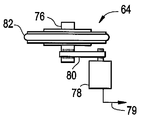
装置40を通過する板ガラスの進行を追跡するため、拘束デバイス62の少なくとも1つのローラが回転式エンコーダデバイスを含んでもよい。回転式エンコーダデバイスは、回転するローラの回転運動を検出し、回転運動を電気信号に変換する。図6は、ローラ軸76と、ローラ軸76および駆動ベルト80を介してローラに結合された回転式エンコーダ78とを含む固定位置ローラ64の側面図を示す。当技術分野において公知のように、回転式エンコーダ78を結合する他の方法を用いてもよい。回転式エンコーダ78はローラの回転比で回転し、電気信号79を発生させる、または変更する。回転式エンコーダ78により発生した、または変更された電気信号79は、その後、受信用計算デバイス(図示せず)に伝達されてもよい。受信用計算デバイスでは、回転式エンコーダからの回転データを使用して板ガラスの直線運動を計算することができる。図6に最も良く示すように、各固定位置ローラ64および各可動可能なローラ66は、ローラと板ガラスとの間の接触から生じる損傷を防ぐための弾性表面82を含む。
To track the progress of the glazing through the
ここで図7および図8を参照すると、空気軸受44は、略平坦な主表面46を含む多孔質体84を含む。本明細書では、多孔質とは、剛体だが、材料の厚さ全体に無数の微細な不規則な流路を含むため、その外部表面に穴が一様に分布し、各穴が単独ではほぼ意味をなさない海綿状の材料であることを意味する。しかしながら、多孔質材料に加圧気体が供給されると、穴は共に材料の表面から実質的に均一な空気の流れを供給する。本定義を維持するのに適した多孔質材料は黒鉛である。焼結金属粉などの他の材料も使用してもよいが、金属の硬質研磨特性によりガラス表面に傷が付く危険性が増すため、黒鉛のようなより軟質の材料が良いとされる。図9に示すように、板ガラスがコンベヤ48から垂直に吊されている際、板ガラスの高さが垂直方向における板ガラスの寸法である場合、多孔質体84の全体的な高さDは、通常、測定されるべき板ガラス28の高さHの2分の1以下であり(破線88の位置がH/2を示す)、好ましくは、多孔質体84の高さは板ガラスの高さの3分の1以下または未満である。さらに、同様に図9に示すように、作動時、空気軸受が板ガラスの底部部分のみに隣接して配置されることが好ましい。つまり、空気軸受は、好ましくは、多孔質体84が板ガラスの下半分またはそれ未満もしくはその一部のみに隣接するように配置される。多孔質体84が板ガラス上に(例えば、破線88を越えて)高く配置された場合、コンベヤのクランプ機構と空気軸受によって加えられる拘束との両方によって板ガラスにかけられる拘束により発生する過度の応力が板ガラスにかかる可能性がある。発生する応力は板ガラスを破損するおそれがある。
Referring now to FIGS. 7 and 8, the
図7に戻ると、多孔質体84は、第1の、すなわち内部多孔質体部分90と、内部多孔質体部分の周りに配置された、第2の、すなわち外部多孔質体部分92とにさらに分割されている。したがって、平坦な主表面46は、内部多孔質体部分90を含む内部平坦表面94と、外部多孔質体部分92を含む外部平坦表面96とに分割されている。内部平坦表面94と外部平坦表面96は同一平面上にあってもよい。
Returning to FIG. 7,
空気軸受44の内部多孔質体部分90は、内周の中心から半径r1で画定される環状の内周98と、内周の中心から半径r2で画定される外周100とを有する環状の形状である。加えて、内周98は、空気軸受44内に延在する通路102の外周を示す。典型的な実施形態では、通路102は直径約3cm〜約8cmの範囲である。しかしながら、通路102は、必要によって、および実施される測定の性質によって、より大きくても、より小さくてもよい。測定デバイス104(図2を参照)は、空気軸受44が板ガラス28と測定デバイス104との間に配置されるように、かつ測定デバイスの光軸105が通路102全体に延びるように配置されている。(測定デバイス104によって固定された)検査面とガラスの面とが同一平面上にあるため、そのような「全体的な」測定が有益となる。図7に示すように、光軸105は、例えば、内周98の中心に一致してもよい。他の実施形態では、測定デバイス104は、板ガラス28が測定デバイス104と空気軸受44との間にあるように配置してもよい。それでも、測定デバイス104は、なお、測定デバイスの光軸105が通路102を貫通するように並ぶよう配置されるべきである。しかしながら、特定の実施形態においては、多孔質体84に面した板ガラス28の側部から測定が行われる場合、多孔質体84からの光の反射が、実施される特定の測定の質に影響を及ぼさないのであれば、またはそうでなければ実施される特定の測定の妨げにならないのであれば、通路102を排除してもよい。測定デバイス104の光軸105は、例えば、測定デバイスが板ガラス28に向かって発するレーザービームであってもよい。
The inner
ここで図10を参照すると、内部多孔質体部分90は、内周98と同心の少なくとも1つの環状溝106を含む。内部多孔質体部分90は、内部平坦表面94において半径方向に延びて、環状溝106と交差する複数の溝108をさらに含む。半径方向の溝108は、好ましくは、スポークのような様式の周期的な角度位置で配置されている。環状溝106および交差する半径方向の溝108は内部平坦表面94を複数の下位表面87に分割する。上述したように、各下位表面87は、真空源(図示せず)と流体連通している少なくとも1つの真空ポート110を含む。
Referring now to FIG. 10, the inner
内部多孔質体部分90のように、空気軸受44の外部多孔質体部分92は弓形の形状であるが、環状の外周を有している必要はない。例えば、外部多孔質体部分は長円形状または楕円形状であってもよい。外部多孔質体部分92は内部多孔質体部分90の周りに配置され、上記の内部多孔質体部分90の中心からの半径r3で画定される環状の内周112を含む。外部多孔質体部分92が環状の外周、すなわち図7に示す周114を含む実施形態では、外周114は内周98の中心からの半径r4で画定される。いくつかの実施形態では、r2=r3であるため、外部多孔質体部分92の内周112は内部多孔質体部分90の外周100と同じである。
Like the inner
さらに図10に関して述べると、外部多孔質体部分92は、外部平坦表面96に形成された複数の連続的な溝116をさらに含む。各連続的な溝116は、多孔質体内に延び、真空源に連結している複数の真空ポート118を含む。好ましくは、複数の真空ポート118は、特定の連続的な溝に配置された真空ポート間の角変位が等しくなるように各連続的な溝116内に周期的に並んでいる。例えば、特定の連続的な溝116内では、真空ポート118は溝の周りに5度毎、10度毎または15度毎に配置されてもよい。1つの連続的な溝116の真空ポートが別の連続的な溝116の真空ポートと角度的に一致している必要はない。いくつかの場合においては、特に、外部多孔質体部分92の外周が環状である場合、連続的な溝116は好ましくは環状かつ同心である。
With further reference to FIG. 10, the outer
図11に示すようないくつかの実施形態では、空気軸受44が複数の内部多孔質体部分90を含んでもよい。複数の内部多孔質体部分90は外部多孔質体部分92内に配置され、各内部多孔質体部分は通路102を画定する。これは、板ガラスの複数の特性を同時に決定するために複数の測定を実施し、単一の測定デバイスに組み込むことができない場合に特に有用となりうる。
In some embodiments, such as that shown in FIG. 11, the
溝および真空ポートの構成は、図12Aおよび図12Bの支援でより良く見ることができる。図12Aは、内部多孔質体部分90の一部の断面図を示す。図12Bは、外部多孔質体部分92の一部の断面図を示す。内部多孔質体部分90と外部多孔質体部分92との両方に、矢印117で示されるように各多孔質体部分の平坦表面から放出される空気などの加圧気体が供給される。矢印119で示される、真空ポートにおいて生成される真空と、多孔質体部分の平坦表面上に生じる気圧が、共に、2つの領域を画定する。この2つの領域とは、外部平坦表面96に隣接する低精度捕捉領域と、内部平坦表面94に一致する高精度捕捉領域である。低精度捕捉領域では、板ガラスの浮上高さは高精度捕捉領域に隣接する板ガラスの浮上高さよりも大きくてもよい。低圧捕捉領域に隣接する板ガラスの浮上高さは、通常、約40μm〜60μmの範囲とされうる。一方では、高精密領域に隣接する板ガラスの浮上高さは、通常、40μm未満とされうる。
The configuration of the grooves and the vacuum port can be better seen with the assistance of FIGS. 12A and 12B. FIG. 12A shows a cross-sectional view of a portion of the inner
上述したように、および図2および図3の実施形態によれば、装置40は、装置40を通過する板ガラス28の移動の方向50を基準として空気軸受44の上流側に配置された複数の安定化エアナイフ52a、52bを含む。複数の安定化エアナイフは、第1の安定化エアナイフが板ガラス28の第1の主表面121(図18を参照)に対向して位置するように配置された第1の安定化エアナイフ52aと、第2の安定化エアナイフが板ガラス28の第2の主表面123に対向して位置するように配置された第2の安定化エアナイフ52bとを含む。板ガラス28の第1の主表面121は、板ガラスが空気軸受に隣接している際、多孔質体84に最も近い板ガラスの表面である。一方で、第2の主表面123は、同じ条件下において多孔質体84から最も遠い板ガラス28の表面である。複数の安定化エアナイフの少なくとも第1の安定化エアナイフおよび第2の安定化エアナイフからの空気の流れは、板ガラスが安定化エアナイフ間の空間に入ると、板ガラスの側方の(横方向の)動きを少なくとも1つの縁案内デバイス54とともに安定させ、板を平坦にする。より簡潔に述べると、板ガラスの上縁にあるコンベヤクランプ機構49と板ガラスの下縁にある縁案内デバイス54とによって、板ガラスの上縁および下縁における側方への動きが妨げられたとしても、板ガラスは、布帆が風で膨らむことができるのとほぼ同じように、板ガラスの全体的な面に垂直な方向になお変形する可能性がある。これは、板ガラスが非常に大きく、非常に薄い場合があるため、より厚いガラスプレートと比較した場合に、板ガラスの可撓性が高くなるためである。例えば、板ガラスの厚さは1mm未満とすることができる。
As described above, and according to the embodiment of FIGS. 2 and 3, the
各安定化エアナイフは、板ガラスの主表面上にさらなる空気の層流を生成し、乱流と後の板ガラスのバフェッティングを防ぐために、各安定化エアナイフからの空気の流れが板ガラスに向かって下方に、全般的に板ガラスの底部に向かって案内されるように配向される。必ずというわけではないが、好ましくは、第1の安定化エアナイフ52aと第2の安定化エアナイフ52bとは板ガラスを挟んで互いに同じになるように配置されている。例えば、図2および図3の実施形態などのいくつかの実施形態では、複数の安定化エアナイフは、好ましくは、複数の対の、部分的に、または実質的に対向するエアナイフとして配置されている。つまり、エアナイフは互いに正対してもよいが、これは必須ではなく、そのような「対」のエアナイフ間に多少の片寄りがあってもよい。しかしながら、いくつかの実施形態では片寄りが大きくてもよい。安定化エアナイフの数はプロセスに依存し、例えば、板ガラスの搬送速度、板ガラスの大きさおよび重さ、特定の製造プロセスラインにおいて板ガラスが呈する横方向の揺れの量に依存する。同様に、板ガラスのもう一方の側における別のエアナイフの配置と比較した板ガラスの一方の側におけるエアナイフの正確な配置は、設備の特定のプロセス条件に依存する。
Each stabilized air knife creates a further laminar flow of air on the main surface of the glass sheet, and the air flow from each stabilized air knife is lowered toward the glass sheet to prevent turbulence and subsequent sheet glass buffeting. And generally oriented to be guided toward the bottom of the glass sheet. Although not necessarily, preferably, the 1st
図13は、細長いオリフィス124を有する略細長い本体122を含む、(ここでは全体として参照番号120で示す)例示的な安定化エアナイフを示す。細長いオリフィス124から空気の流れ126が発生する。簡略化のため、エアナイフは長手方向に延びる矩形のブロックで示される。各細長いオリフィス124は継手を通じてエアナイフに入る加圧気体源と流体連通している。エアナイフは、オリフィス124と流体連通している内部プレナムを含んでもよい。空気が、豊富であるとともに実質的に無料であり、気体として大変満足なものであるため、残りの説明では空気ベースのエアナイフを想定する。各細長い本体122は、各細長いオリフィス124から放出される空気の流れの方向が基準水平面に対して下方角度であるように配置されている。例示的な安定化エアナイフ120によって示されるような各安定化エアナイフは、板ガラスの移動する方向50を基準とした前方端または先端Lと、後方端または後端TRとを含む。つまり、エアナイフの先端はエアナイフの後端よりもさらに先の上流側である。エアナイフに加圧空気が供給されると、空気が細長いオリフィス124から高速で放出される。細長いオリフィス124から放出される空気は、安定化エアナイフを離れた後、約数十ミリメートルの少なくとも短い距離の間、最終的に分岐し始めてもよいが、空気は実質的に面に近似しうる層流126としてエアナイフから放出される。例示的な安定化エアナイフ120は頂部表面Tをさらに含む。
FIG. 13 shows an exemplary stabilized air knife (generally indicated by
安定化エアナイフが補完的な(すなわち、空気軸受の主表面46と平行する安定化エアナイフ間に介在する垂直面を挟んで同じである)対向関係において配置された場合、対向する安定化エアナイフの対の先端間の距離は、対向する安定化エアナイフの対の後端間の距離より大きくてもよい。つまり、対向するエアナイフ間の距離は、ガイドスロット58が狭くなるのと同様の方式で板ガラスがエアナイフ間を進むにつれて狭くなる。
When the stabilizing air knives are arranged in a complementary relationship (ie the same across a vertical plane interposed between the stabilizing air knives parallel to the
さらに別の任意の特性では、複数の安定化エアナイフの各安定化エアナイフは、各安定化エアナイフの後端が安定化エアナイフの先端よりも高くなる(または低くなる)ように配向してもよい。いくつかの実施形態では、各安定化エアナイフは、例示的なエアナイフ120に類似する真直(すなわち、矩形形状)とすることができる。しかしながら、好ましくは、各安定化エアナイフは弓形であり、円弧を含んでもよい。真直な(直線の)種類、または弓形の設計のいずれかの適切な安定化エアナイフは、例えば、Cincinnati、Ohio、USAにあるExair Corporationから得られる。
In yet another optional characteristic, each stabilizing air knife of the plurality of stabilizing air knives may be oriented such that the trailing end of each stabilizing air knife is higher (or lower) than the tip of the stabilizing air knife. In some embodiments, each stabilizing air knife can be straight (ie, rectangular) similar to the
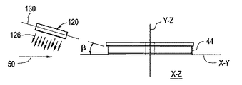
各安定化エアナイフをどう空間的に配向してもよいかが以下の説明および図14〜図16の支援によりさらに詳細に視覚化されうる。3次元空間における本体の向きには、基準座標系と、その基準座標系に本体を配向する手段とを必要とする。図14は、多孔質体84の主表面46と同一平面上にある垂直X−Y面を示す。さらなる説明のため、このX−Y面は3次元のデカルト座標系の基準座標系において1つの面を形成する。このX−Y面は図14が示されるページの面内に配置される。第2の垂直面は、図14においてその縁から見ると、Z方向がページに垂直に延び、したがって、ページから出るデカルト座標系のY−Z面を形成する。Y−Z面はX−Y面に垂直である。第3のX−Z面は、また、図14においてその縁から見ると、X−Y面とY−Z面との両方に垂直となるように配置されている。さらなる説明のため、および特に説明しない限りは、上記の3つの面X−Yと、Y−Zと、X−Zとによって形成されるデカルト座標系の原点は内部多孔質体部分90の中心にあり、このデカルト座標系は、3次元空間におけるエアナイフの向きを説明するために使用される。
How each stabilizing air knife can be spatially oriented can be visualized in more detail with the help of the following description and FIGS. The orientation of the main body in the three-dimensional space requires a reference coordinate system and means for orienting the main body in the reference coordinate system. FIG. 14 shows a vertical XY plane that is coplanar with the
図14〜図16は、例示的な安定化エアナイフ120の3つの任意の向き、ひいては、したがって、向きの視覚化を支援するために別個に示される各安定化エアナイフの任意の空間的向きを示す。図14は、主表面46に着目して見た空気軸受44の外形を示すとともに、板ガラスの移動する方向50を示す。例示的な安定化エアナイフ120は、水平X−Z面を基準として、安定化エアナイフの先端Lが安定化エアナイフの後端TRよりも低い下降勾配または傾斜を示す。すなわち、面128は、例示的な安定化エアナイフからの空気の流れがX−Z面とともに角度αを形成することを示す。
FIGS. 14-16 illustrate the three arbitrary orientations of the exemplary stabilizing
図15は、空気軸受44の縁を見下ろす第2の図を示すとともに、Y−Z面の縁およびX−Y面の縁を示す。X−Z面は、X−Y面とY−Z面との両方に対して垂直である。面130は、例示的な安定化エアナイフ120の頂部表面Tを長手方向に二分する面であり、かつエアナイフからの空気の流れを示す面126に垂直である。図15によれば、例示的な安定化エアナイフ120は、非ゼロの角度βが面130とX−Y面との間に形成されるように、垂直なX−Y面に対して角度をなしてもよい。
FIG. 15 shows a second view looking down at the edge of the
図16は、空気軸受44の縁を見下ろす第3の図を示すとともに、X−Z面の縁およびX−Y面の縁を示す。Y−Z面は、X−Y面とX−Z面との両方に対して垂直である。図16は、エアナイフを出る空気の流れが、例えば、板ガラスに垂直に案内される代わりに、(例えば、水平なX−Z面と平行する基準水平流から)下方に案内され、空気流の面がX−Y面とともに鋭角σを形成するようにその端部から配向された例示的な安定化エアナイフ120を示す。好ましくは、σは、約15度〜約75度の範囲、好ましくは、約25度〜約65度の範囲、より好ましくは、約35度〜約55度の範囲である。一実施形態において、空気流の角度は垂直のX−Y面に対して約45度である。空気流の好ましい方向は下方であることに留意されたい。その理由は、板ガラスに対して空気軸受を低く配置すると空気流による板ガラスの座屈に耐えるためのさらなる剛性が板ガラスの下部に付与されるからである。しかしながら、いくつかの実施形態では、プロセス条件および特定の実施、例えば、空気軸受の位置決めによっては上方の空気流が好まれてもよい。
FIG. 16 shows a third view looking down on the edge of the
上記の説明では、例示的な安定化エアナイフ120の3つの任意の向きを示した。複数の安定化エアナイフの各安定化エアナイフは、代表例な、例示的な安定化エアナイフに関して上記の3つの任意の向きの少なくとも1つの向きを呈してもよい。例えば、複数の安定化エアナイフの各安定化エアナイフは、エアナイフからの空気流の方向がほぼ下方(すなわち、流れのベクトルが垂直ベクトル成分を含む)になるように空気を排出してもよい。したがって、例えば、板ガラスの両側にあり、安定化エアナイフが互いに対称になっている、2つの安定化エアナイフは、「V」が下方を向いた略V字形の空気の流れを形成する。
In the above description, three arbitrary orientations of the exemplary stabilized
同様に、複数の安定化エアナイフの各安定化エアナイフは各安定化エアナイフの先端が後端よりも板ガラスから離れるように配向してもよい。したがって、例えば、板ガラスの両側にあり、安定化エアナイフが互いに対称になっている2つの安定化エアナイフは、「V」が空気軸受に向かって下流側を向いた略V字形の空気の流れを形成する。これが、エアナイフ間に入る際に側方の動きを呈する板ガラスにさらなる側方の間隙を提供する。各安定化エアナイフの先端からの空気の流れから板ガラスにかかる圧力が安定化エアナイフの後端に隣接する板ガラスにかかる空気の圧力より小さくなるため、それは、また、安定化エアナイフから流れる空気のカーテンをより緩やかに適用する。 Similarly, each stabilizing air knife of the plurality of stabilizing air knives may be oriented such that the tip of each stabilizing air knife is farther from the glass sheet than the rear end. Thus, for example, two stabilizing air knives on both sides of a glass sheet, where the stabilizing air knives are symmetrical with each other, form a generally V-shaped air flow with “V” facing downstream toward the air bearing. To do. This provides additional lateral clearance in the glass pane that exhibits lateral movement as it enters between the air knives. Because the pressure on the glass sheet from the air flow from the tip of each stabilizing air knife is less than the air pressure on the glass sheet adjacent to the trailing edge of the stabilizing air knife, it also reduces the curtain of air flowing from the stabilizing air knife. Apply more slowly.
同様に、複数の安定化エアナイフの各安定化エアナイフは、各安定化エアナイフの先端が、水平基準面(例えばX−Z面)を基準として、後端よりも低くなるように配向してもよい。板の任意の形状歪み(例えばそり)を平坦にするため、安定化エアナイフを前方に勾配させる、または傾斜させると言われる。 Similarly, each stabilizing air knife of the plurality of stabilizing air knives may be oriented such that the tip of each stabilizing air knife is lower than the rear end with respect to a horizontal reference plane (for example, the XZ plane). . It is said that the stabilizing air knife is tilted forward or tilted to flatten any shape distortion (eg warpage) of the plate.
複数のエアナイフの各安定化エアナイフは上記の1つまたは複数の向きを呈してもよい。いくつかの実施形態では、1つまたは複数の安定化エアナイフは、すべての3つの向きを同時に呈してもよい。 Each stabilizing air knife of the plurality of air knives may exhibit one or more of the orientations described above. In some embodiments, one or more stabilizing air knives may exhibit all three orientations simultaneously.
安定化エアナイフに加えて、および図3に見られるように、例えば、第1の位置決めエアナイフからの空気の流れ126が空気軸受の前縁に隣接する板ガラスの第1の主表面121にあたるように、第1の位置決めエアナイフ132を安定化エアナイフ(52a、52b)と空気軸受44との間に配置してもよい。例えば、第1の位置決めエアナイフ132は空気軸受44上に約270度の位置で配置してもよい。板ガラスが第1の位置決めエアナイフ132に隣接して通過する際に板ガラス上に生成される圧力が板ガラスを空気軸受から離す。これにより、板ガラスが板ガラスを空気軸受によって「捕捉」することができるまで空気軸受に近づくため、板ガラスの前縁または前方縁間の接触が防止される。
In addition to the stabilizing air knife and as seen in FIG. 3, for example, so that the
第2の位置決めエアナイフ134は、第2の位置決めエアナイフからの空気が板ガラスの第2の主表面123にあたるように配置してもよい。第2の位置決めエアナイフからの空気の効果は、板ガラスを空気軸受に向かう方向に押すため、板ガラスが空気軸受に近づき、空気軸受が板ガラスを捕捉することを可能にすることである。板ガラスの最初の捕捉は外部多孔質体部分によって生じた圧力と真空との組み合わせによって達成される。
The second
第3の位置決めエアナイフ136は空気軸受から下流側に配置してもよく、第3の位置決めエアナイフによって放出される空気が板ガラスの第1の主表面121に対して案内されるように配置される。第3の位置決めエアナイフ136によって生成される空気圧力は板ガラスを空気軸受の下流側縁近辺の空気軸受面から離し、それによって、板ガラスが空気軸受を通過し、空気軸受から離れる際に、板ガラスと空気軸受との間の接触を防ぐ。各位置決めエアナイフ132、134および136は設計が安定化エアナイフに類似していてもよい。例えば、各安定化エアナイフおよび各位置決めエアナイフは、弓形の設計のものでも、直線の設計のものでもよい。好ましくは、位置決めエアナイフ132、134および136のそれぞれから放出される空気は、各位置決めエアナイフからの気体のカーテンが、板ガラスの表面とともに90度未満だがゼロより大きい角度、例えば、25度超および75度未満、好ましくは35度超および65度未満、好ましくは35度超および55度未満の角度を形成するように板ガラスに案内される。例えば、典型的な実施形態では、空気の流れが約45度の角度で板ガラスにあたるように各位置決めエアナイフを配向してもよい。90度未満の衝突角度では、例えば、板ガラスに垂直な空気流に比べ、板ガラスの表面において生成される乱流が少なくなる。
The third
装置40の種々の非接触式板ガラスハンドリング構成要素の全体的な効果は、測定のために板ガラスを用意するため段階的に増加する拘束を板ガラスに提供することである。上述したように、いくつかの例において、板ガラスはコンベヤのクランプ部によって板ガラスの上部においてのみ固定されて垂直に搬送される。板ガラスが非常に薄く、1mm以下、場合においては0.7mm以下、または他の場合においては0.3mm以下である場合があるため、ガラスは横方向に揺れることによる側方の動きを容易に示すおそれがある(すなわち、固定された搬送台の接触点を中心として回転する)、または種々の曲げモードにより変形するおそれがある(本明細書では、曲げモードは振動モードに類似している)。ガラスは、また、搬送台毎の固定におけるばらつきおよびコンベヤにおける搬送台の位置のために片寄る可能性がある。同様に、ガラスは垂直に反る可能性がある。
The overall effect of the various non-contact glazing handling components of the
装置40の種々の板ガラスハンドリング構成要素は、これら動きおよび反りなどの固定形状を低減するように、または除去するように機能する。したがって、装置40の操作は以下のステップに沿って進めてもよい。
The various glass handling components of the
板ガラスを板ガラスの上縁に沿って把持し、板ガラスを装置40中において平行移動させる1つまたは複数のクランプ機構49によって、板ガラス28をコンベヤ48に取り付ける。板ガラス28はそれによって1つまたは複数のクランプ機構から吊され、板ガラスの上部部分に沿って板ガラスを固定した1つまたは複数のクランプ機構のみによって支持される。板ガラスの下縁63は支持されず、装置40に入る前に、側方への動き、すなわち左右の動きが最初に可能となる。側方への動きに加えて、板ガラスは、また、たわみまたは曲げを呈する可能性がある。例えば、板は、円筒状にまたは双曲状に曲がる可能性がある、もしくは鞍形、ドーム形になる可能性がある、もしくは他の曲げモードまたはその組み合わせを呈する可能性がある。
The
板ガラス28が装置40に近づくと、板ガラスは、板ガラスの下縁63と係合し、安定化エアナイフ52aと、安定化エアナイフ52bとの間に板ガラスの前縁を案内する少なくとも1つの縁案内デバイス54によって案内される。下縁63は板ガラスの「低品質」部の部分を形成し、後に取り除かれてもよい。少なくとも1つの縁案内デバイス54は横方向の揺れを最小化する、または取り除く。試験は、本明細書中に開示したような縁案内デバイス54の実施形態によって、最大変位の+/−75mmから+/−10mm未満まで揺れの側方の動きを低減することができることを示した。しかしながら、少なくとも1つの縁案内デバイス54が板ガラスの下縁の側方への動きの優れた制御を提供することができる一方で、板ガラスは上縁および底縁においてのみ実質的に拘束され、なお板ガラスの本体内において種々の曲げモードおよび固定形状を呈することが可能である。多孔質体84の近傍に移動する前に板ガラスのこの余分な動きまたは形状を最小化するため、または取り除くために、安定化エアナイフが用いられる。
As the
対向する安定化エアナイフによって好ましくは下方に放出される空気の流れは、板ガラスの横方向の揺れを取り除くため、特に、曲げモードを低減するために、または排除するために板ガラスの側方への動きをさらに低減してもよい。事実上、安定化エアナイフは、曲げの大きさを少なくとも低減することによって、および場合においては、1つまたは複数の曲げモードを排除することによって、板ガラスの補強を支援する。安定化エアナイフの数および位置は、板ガラスの大きさ、板ガラスの厚さ、ガラスの密度、および装置40を通過する板ガラスの横断速度のような要素に依存する。
The flow of air, preferably released downwards by the opposing stabilizing air knife, eliminates lateral swaying of the glazing, in particular lateral movement of the glazing to reduce or eliminate bending modes. May be further reduced. In effect, stabilized air knives help to reinforce the glazing by at least reducing the magnitude of bending and, in some cases, by eliminating one or more bending modes. The number and location of stabilizing air knives depends on factors such as the size of the glass sheet, the thickness of the glass sheet, the density of the glass, and the crossing speed of the glass sheet passing through the
板ガラスが安定化エアナイフ間を通過する際、板ガラスの下縁63を、板ガラスをさらに案内し、安定させるために、1つまたは複数の追加の縁案内デバイス54によって案内してもよい。例えば、いくつかの実施形態では、複数の縁案内デバイスは、安定化エアナイフの上流側において用いられている第1の縁案内デバイスと、縁拘束デバイス62の直前に配置された第2の縁案内デバイスとともに用いてもよい。
As the glass sheet passes between the stabilizing air knives, the
板ガラスが空気軸受44に近づくと、板ガラスの第1の主表面121において空気の流れを案内するために任意の第1の位置決めエアナイフ132を使用してもよい。板ガラス28の第1の主表面121に対する第1の位置決めエアナイフ132からの空気の力が板ガラスを空気軸受44の前縁140から押し離し(図17、および特に図18の領域Aを参照)、板ガラスが空気軸受44の外部多孔質体部分92の影響下に置かれた際、空気軸受の前縁140と板ガラス28の前縁141との間の接触を防ぐ。板ガラスと空気軸受との間の接触は、板ガラスの、場合によっては致命的な破損につながるおそれがある。
As the glass sheet approaches the
板ガラスが移動する方向50に沿って前進を続けると、板ガラスは外部多孔質体部分92の第1の真空ポート118上を通過する。好ましくは、外部多孔質体部分92の最も外側の溝内に配置された真空ポート118が、板ガラスが前進すると、板ガラスがまずこの単一の真空ポート118の近傍に移動するように配置されるように、空気軸受44が配置されている。図10を参照すると、この第1の真空ポート118は、左に最も遠く、図10において最も外側にある連続的な溝116内に配置され、破線119と交差する真空ポートである。第1の真空ポート118とのこの最初の接触の効果は、板ガラス28の前縁141が外部多孔質体部分92により接近することである。つまり、空気軸受の前縁141に隣接する板ガラスの領域が空気軸受の前縁から押し離される一方、第1の真空ポート118に隣接する板ガラスの領域は外部多孔質体部分92の方向に押し動かされる。第1の真空ポート118に隣接する板ガラスの少なくともこの部分を空気軸受に近づけることによって、板ガラスのその部分が空気軸受44の外部多孔質体部分92によって捕捉される。板ガラスの継続的な前方移動が板ガラスを外部多孔質体部分92の追加の真空ポート118に隣接させる。追加の外部多孔質体部分の真空ポート118に隣接して通過する板ガラス28の前縁の短い距離内では、外部多孔質体部分における空気流のため十分な力が板ガラスに作用する。外部多孔質体部分では、空気軸受44に隣接する板ガラスのかなりの部分が空気軸受の第1の主表面に対して実質的に均一な浮上高さを呈する。
As the plate glass continues to advance along the
また、板ガラスが内部多孔質体部分90に隣接して前進を続けるため、通路102を通じて測定デバイス104により測定を実施することができるように、特に、内部多孔質体部分90に直に隣接した板ガラス28の部分における板ガラスの平坦さと剛性が増加する。
Also, since the glass sheet continues to advance adjacent to the inner
板ガラス28の表面トポグラフィーを判定するための干渉測定などの板ガラスの測定を、板ガラスの前方(すなわち方向50の)移動と同時に実施してもよいことを想起されたい。板ガラスの後縁が内部多孔質体部分90、その後、外部多孔質体部分92を通過すると、空気軸受44の動作によって加えられる板ガラスの拘束が低下し、板ガラスと空気軸受との間の接触が生じないよう板ガラスの後縁が空気軸受から押し離されるように、任意の位置決めエアナイフ136からの空気圧力が空気軸受44によって加えられる保持力を克服することができる。例えば、板ガラスの浮上高さが約30μm未満(+/−15μm)の偏差を有するように維持されるように、内部多孔質体部分90に供給される加圧空気および真空を調節してもよい。
Recall that plate glass measurements, such as interferometry to determine the surface topography of the
上述より、板ガラスが空気軸受44を通過すると板ガラスの特定の領域が通路102に対向することがわかる。したがって、通路102は環状の測定領域を画定する一方で、図9に示すように、板ガラスの矩形の測定領域138を「一掃」する。測定デバイス104はこの矩形領域内のガラスの連続測定を行う。例えば、測定デバイス104は、矩形の測定領域内の板ガラスの表面トポグラフィー測定を実施するための干渉計であってもよい。または、測定デバイス104は板ガラスの厚さの測定を実施してもよい。
From the above, it can be seen that when the plate glass passes through the
最終的に、移動する方向50に沿った板ガラスの継続的な前方移動によって板ガラスの後縁142が空気軸受44を通過する。第3の位置決めエアナイフ136から放出され、板ガラスの第1の主表面121にあたる空気が空気軸受44の後縁142に近接する板ガラスの領域を空気軸受から離し、それによって板ガラスと空気軸受面との間の接触を防止する。これは、安定化エアナイフおよび/または空気軸受の影響下にある板ガラスの表面積が減少するため特に有利になる。
Finally, the trailing
位置決めエアナイフ132、134および136によって供給される力の結果は、装置40を頂面図において示すとともに、板ガラス28を示す図18の支援により理解することができる。位置決めエアナイフ132および136の効果が、参照符号AおよびBで示され、かつ破線で囲まれた領域において見られる。実際、図18から、板ガラス全体は板ガラスが空気軸受に完全に係合するまで非平面態様をとることがわかる。この箇所では空気軸受に隣接する板ガラスは完全に平坦であるが、平坦度が必要な領域は測定が実施される箇所のみ、例えば、測定領域の中心であることに留意されたい。
The result of the force supplied by the positioning
図19は、内部多孔質体部分の中心から空気軸受の前縁まで延びる板ガラスの縁の図を示すとともに、空気軸受上の板ガラスの形状をより詳細に示す。対象とするゆがみが約数十マイクロメートルであるため、図19の図は大幅に誇張されていることに留意されたい。示したように、板ガラスは、同様に異なる境界によって分離されるいくつかの異なる領域に分割することができ、空気軸受上にある板ガラスの部分がS字形の境界特徴145によって分離される一連の比較的平坦な水平域144の外観になる。水平域の浮上高さは内部多孔質体部分の中心に向かう方向に減少する(例えば、通路102によって画定される領域)。
FIG. 19 shows a diagram of the edge of the glass sheet extending from the center of the inner porous body portion to the leading edge of the air bearing and shows the shape of the glass sheet on the air bearing in more detail. Note that the view of FIG. 19 is greatly exaggerated because the warping of interest is about tens of micrometers. As shown, the glass pane can be divided into several different regions that are also separated by different boundaries, and a series of comparisons in which the portion of the glass pane on the air bearing is separated by an S-shaped
図20は、移動速度100mm/秒で、板ガラスの2つの異なる位置において測定した、装置40の一実施形態内を移動する板ガラスについて測定した浮上高さのグラフである。縦軸「Y」は浮上高さをマイクロメートルで示し、横軸「X」は時間を示す。測定は特定の位置において所定の周波数(250/秒)で実施した。したがって、図20のグラフは、空気軸受に隣接して板ガラスが移動する際、特定の時間にわたり所定の位置における浮上高さを得るために使用することができる。板ガラスは、当初、名目的な中心線位置から+/−75mmの横方向の揺れを有した。各安定化エアナイフは空気を板ガラスに対して45度の下方角度で案内した。空気軸受の内部多孔質体部分には、20psi(137931.034482Pa)〜60psi(413793.103446Pa)の圧力、0.63+/−0.25CFMの流量で空気が供給された。一方、外部多孔質体部分には、40psi(275862.068964Pa)〜85psi(586206.8965485Pa)の圧力および0.96+/−0.35CFMの流量で空気が供給された。通路102によって画定される環状の測定領域上における板ガラスの浮上高さは名目上28μmであり、ばらつきは+/−2.5μm未満であった。図20の曲線146は、約210度の位置における、内部多孔質体部分材90の外周における板ガラスの浮上高さを示す。この板ガラスは100mm/秒の速度で移動する。一方、図20の曲線148は、内部多孔質体部分の中心(すなわち通路102の中心)における浮上高さを示す。板ガラスの移動における曲線は、板ガラスの、外部多孔質体部分の外周における測定位置と多孔質体の中心上における測定位置との両位置における浮上高さの安定性を示すことを特に示している。名目的な浮上高さは2つの領域間において異なり、多孔質体の中心よりも外部多孔質体位置においてかなり高いが、両位置における浮上高さは驚くほど安定しており、約±2.5マイクロメートル未満のばらつきを示す。
FIG. 20 is a graph of flying height measured for a sheet glass moving within one embodiment of the
本発明の趣旨及び範囲から逸脱することなく本発明に対して様々な修正及び変形を行えることは当業者には自明であろう。したがって、本発明は、この発明の変更形態および変形形態が添付の特許請求の範囲およびその均等物に含まれる限り、それらを包含するものである。 It will be apparent to those skilled in the art that various modifications and variations can be made to the present invention without departing from the spirit and scope of the invention. Thus, it is intended that the present invention cover the modifications and variations of this invention provided they come within the scope of the appended claims and their equivalents.
6 フュージョンダウンドローガラス製造システム
8 バッチ材料
10 融解炉
12 溶融ガラス材料
14 精製部
16 撹拌装置
18 受容容器
20 成形主要部
22 開きょ
24 収束外部成形面
26 ガラスリボン
28 板ガラス
29 切断線
30 融解部と精製部との連結管
32 精製部と撹拌装置との連結管
34 攪拌部と受容容器との管
36 下降管
38 成形主要部入口
40 装置
42 フレーム
44 空気軸受
46 主表面
48 コンベヤ
49 クランプ機構
50 移動の方向
52a 第1の安定化エアナイフ
52b 第2の安定化エアナイフ
54 縁案内デバイス
56a、56b ガイドアーム
58 ガイドスロット
60 相補形の穴
62 縁拘束デバイス
63 下縁
64 固定位置ローラ
66 可動可能なローラ
68 バネ
70 旋回アーム
72 旋回点
74 バネ止め
76 ローラ軸
78 回転式エンコーダ
79 電気信号
80 駆動ベルト
82 弾性表面
84 多孔質体
87 下位表面
90 内部多孔質体部分
92 外部多孔質体部分
94 内部平坦表面
96 外部平坦表面
98、112 内周
100、114 外周
102 通路
104 測定デバイス
105 光軸
106 環状溝
108 溝
110 真空ポート
116 連続的な溝
117、119 矢印
118 真空ポート
119 破線
120 例示的な安定化エアナイフ
121 第1の主表面
122 略細長い本体
123 第2の主表面
124 オリフィス
126 流れ
128、130 面
132 第1の位置決めエアナイフ
134 第2の位置決めエアナイフ
136 第3の位置決めエアナイフ
138 矩形の測定領域
140、141 前縁
142 後縁
144 水平域
145 S字形の境界特徴
146、148 曲線
6 Fusion Down Draw Glass Production System 8 Batch Material 10 Melting Furnace 12 Molten Glass Material 14 Purification Unit 16 Stirrer 18 Receiving Container 20 Molding Main Part 22 Opening 24 Converging External Forming Surface 26 Glass Ribbon 28 Sheet Glass 29 Cutting Line 30 Melting Part Connection pipe 32 to the purification section Connection pipe 34 to the purification section and the stirring device 36 Pipe 36 to the stirring section and the receiving container 36 Downcomer pipe 38 Molding main portion inlet 40 Device 42 Frame 44 Air bearing 46 Main surface 48 Conveyor 49 Clamp mechanism 50 Direction 52a First Stabilized Air Knife 52b Second Stabilized Air Knife 54 Edge Guide Devices 56a, 56b Guide Arm 58 Guide Slot 60 Complementary Hole 62 Edge Constraining Device 63 Lower Edge 64 Fixed Position Roller 66 Movable Roller 68 Spring 70 Rotating arm 72 Rotating point 74 Spring stopper 76 Roller shaft 78 rotary encoder 79 electrical signal 80 drive belt 82 elastic surface 84 porous body 87 lower surface 90 inner porous body portion 92 outer porous body portion 94 inner flat surface 96 outer flat surface 98, 112 inner circumference 100, 114 outer periphery 102 passage 104 measuring device 105 optical axis 106 annular groove 108 groove 110 vacuum port 116 continuous groove 117, 119 arrow 118 vacuum port 119 broken line 120 exemplary stabilizing air knife 121 first major surface 122 substantially elongated body 123 Second major surface 124 Orifice 126 Flow 128, 130 Surface 132 First positioning air knife 134 Second positioning air knife 136 Third positioning air knife 138 Rectangular measuring area 140, 141 Leading edge 142 Trailing edge 144 Horizontal area 145 S-shaped Boundary features 146, 148 Line
Claims (10)
前記板ガラスを垂直方向に支持し、該垂直方向を向いた板ガラスを、前記装置を通過して移動方向に移動するよう構成されたコンベア、
環状の内部多孔質体部分と、前記内部多孔質体部分の周りに配置された外部多孔質体部分とを含む空気軸受であって、前記内部多孔質体部分が該空気軸受の厚さ全体に延びる中心通路を画定し、前記板ガラスが前記装置を通過して移動する際に、前記外部多孔質体部分および前記内部多孔質体部分が前記板ガラスの主表面に隣接して配置されるものである空気軸受、
前記板ガラスが前記装置を通過して移動する際に、前記板ガラスの対向する主表面に隣接して配置され、前記板ガラスの前記移動方向を基準として前記空気軸受の上流側に配置された複数の安定化エアナイフであって、該各安定化エアナイフからの空気流が、前記板ガラスの前記それぞれの主表面に向かって案内されるように配向されるものである複数の安定化エアナイフ、および
前記板ガラスの少なくとも1つの特性を測定するための測定デバイスであって、前記空気軸受の前記中心通路に対向して設けられた測定デバイス、
を備えることを特徴とする装置。 In an apparatus for characterizing a sheet glass as the sheet glass moves through the apparatus,
A conveyor configured to support the plate glass in a vertical direction and move the plate glass facing the vertical direction in the moving direction through the device;
An air bearing including an annular inner porous body portion and an outer porous body portion disposed around the inner porous body portion, wherein the inner porous body portion has an entire thickness of the air bearing. A central passage extending is defined, and the outer porous body portion and the inner porous body portion are disposed adjacent to a main surface of the plate glass when the plate glass moves through the device. Air bearing,
When the plate glass moves through the device, a plurality of stable plates are arranged adjacent to the opposing main surfaces of the plate glass and arranged upstream of the air bearing with respect to the moving direction of the plate glass. A plurality of stabilized air knives, wherein the air flow from each of the stabilized air knives is oriented to be guided toward the respective main surface of the plate glass, and at least one of the plate glasses A measuring device for measuring one characteristic, the measuring device being provided facing the central passage of the air bearing;
A device comprising:
Applications Claiming Priority (2)
| Application Number | Priority Date | Filing Date | Title |
|---|---|---|---|
| US201161526860P | 2011-08-24 | 2011-08-24 | |
| US61/526,860 | 2011-08-24 |
Related Child Applications (1)
| Application Number | Title | Priority Date | Filing Date |
|---|---|---|---|
| JP2016095145A Division JP5974199B1 (en) | 2011-08-24 | 2016-05-11 | Method for characterizing sheet glass |
Publications (3)
| Publication Number | Publication Date |
|---|---|
| JP2013043829A JP2013043829A (en) | 2013-03-04 |
| JP2013043829A5 JP2013043829A5 (en) | 2015-09-10 |
| JP5936952B2 true JP5936952B2 (en) | 2016-06-22 |
Family
ID=47761302
Family Applications (2)
| Application Number | Title | Priority Date | Filing Date |
|---|---|---|---|
| JP2012183870A Expired - Fee Related JP5936952B2 (en) | 2011-08-24 | 2012-08-23 | Apparatus and method for characterizing sheet glass |
| JP2016095145A Expired - Fee Related JP5974199B1 (en) | 2011-08-24 | 2016-05-11 | Method for characterizing sheet glass |
Family Applications After (1)
| Application Number | Title | Priority Date | Filing Date |
|---|---|---|---|
| JP2016095145A Expired - Fee Related JP5974199B1 (en) | 2011-08-24 | 2016-05-11 | Method for characterizing sheet glass |
Country Status (5)
| Country | Link |
|---|---|
| US (2) | US8773656B2 (en) |
| JP (2) | JP5936952B2 (en) |
| KR (1) | KR20130022390A (en) |
| CN (2) | CN202808599U (en) |
| TW (1) | TWI530669B (en) |
Families Citing this family (10)
| Publication number | Priority date | Publication date | Assignee | Title |
|---|---|---|---|---|
| US8773656B2 (en) * | 2011-08-24 | 2014-07-08 | Corning Incorporated | Apparatus and method for characterizing glass sheets |
| AU2014361727B2 (en) * | 2013-12-09 | 2019-07-04 | Hatch Pty Ltd | Measuring apparatus and method for same |
| JP6484482B2 (en) * | 2014-06-30 | 2019-03-13 | AvanStrate株式会社 | Glass plate manufacturing method and glass plate manufacturing apparatus |
| CN107636442B (en) | 2015-03-13 | 2022-01-18 | 康宁股份有限公司 | Edge strength testing method and apparatus |
| WO2016163373A1 (en) * | 2015-04-10 | 2016-10-13 | 旭硝子株式会社 | Glass plate |
| TWI762083B (en) * | 2015-09-17 | 2022-04-21 | 美商康寧公司 | Methods of characterizing ion-exchanged chemically strengthened glasses containing lithium |
| TWI756366B (en) * | 2017-02-24 | 2022-03-01 | 美商康寧公司 | Dome or bowl shaped glass and method of fabricating dome or bowl shaped glass |
| WO2019168951A1 (en) * | 2018-02-28 | 2019-09-06 | Corning Incorporated | Non-contact glass substrate guiding apparatus and method |
| JP2021521084A (en) * | 2018-04-12 | 2021-08-26 | コーニング インコーポレイテッド | Devices and methods for engaging moving glass ribbons |
| WO2020060829A1 (en) * | 2018-09-19 | 2020-03-26 | Corning Incorporated | Glass sheet processing apparatus and method |
Family Cites Families (24)
| Publication number | Priority date | Publication date | Assignee | Title |
|---|---|---|---|---|
| US3062520A (en) * | 1957-08-19 | 1962-11-06 | Sunbeam Corp | Conveying apparatus for sheet material employing fluid support means |
| DE1908109B2 (en) * | 1969-02-19 | 1971-08-05 | Deutsche Tafelglas AG Detag, 3510Furth | Guide device for vertically transported sheet-like goods, especially for the production of double or multiple panes of glass |
| US4824248A (en) * | 1987-12-21 | 1989-04-25 | Environmental Research Institute Of Michigan | Stabilized sensor device |
| DE4343810C1 (en) * | 1993-12-22 | 1995-04-20 | Roland Man Druckmasch | Photoelectric measuring head |
| US5654799A (en) * | 1995-05-05 | 1997-08-05 | Measurex Corporation | Method and apparatus for measuring and controlling the surface characteristics of sheet materials such as paper |
| US5642192A (en) * | 1995-06-12 | 1997-06-24 | Measurex Corporation | Dual spectrometer color sensor |
| US5642189A (en) * | 1995-06-12 | 1997-06-24 | Measurex Corporation | Color sensor simulating standard source illuminant |
| JPH1035882A (en) * | 1996-07-23 | 1998-02-10 | Nippon Electric Glass Co Ltd | Device for continuously carrying plate material to working position without generating contact therewith |
| US6359686B1 (en) * | 1999-06-29 | 2002-03-19 | Corning Incorporated | Inspection system for sheet material |
| US6588118B2 (en) * | 2001-10-10 | 2003-07-08 | Abb Inc. | Non-contact sheet sensing system and related method |
| JP3611563B2 (en) * | 2003-01-09 | 2005-01-19 | 川重プラント株式会社 | Vertical processing line for plate material |
| US7077019B2 (en) * | 2003-08-08 | 2006-07-18 | Photon Dynamics, Inc. | High precision gas bearing split-axis stage for transport and constraint of large flat flexible media during processing |
| US20060042314A1 (en) * | 2004-08-27 | 2006-03-02 | Abbott John S Iii | Noncontact glass sheet stabilization device used in fusion forming of a glass sheet |
| US7908885B2 (en) * | 2004-11-08 | 2011-03-22 | New Way Machine Components, Inc. | Non-contact porous air bearing and glass flattening device |
| US7516628B2 (en) * | 2005-01-11 | 2009-04-14 | Corning Incorporated | On-line thickness gauge and method for measuring the thickness of a moving glass substrate |
| US7567344B2 (en) * | 2006-05-12 | 2009-07-28 | Corning Incorporated | Apparatus and method for characterizing defects in a transparent substrate |
| US20080022811A1 (en) * | 2006-06-30 | 2008-01-31 | Murray Kathan | Power tong having cam followers with sliding contact surfaces |
| US7714996B2 (en) * | 2007-01-23 | 2010-05-11 | 3i Systems Corporation | Automatic inspection system for flat panel substrate |
| KR101298876B1 (en) * | 2007-03-07 | 2013-08-21 | 가부시키가이샤 알박 | Vacuum device and method of conveying substrate |
| US7607647B2 (en) * | 2007-03-20 | 2009-10-27 | Kla-Tencor Technologies Corporation | Stabilizing a substrate using a vacuum preload air bearing chuck |
| KR101587176B1 (en) | 2007-04-18 | 2016-01-20 | 마이크로닉 마이데이타 에이비 | Method and apparatus for mura detection and metrology |
| FI127623B (en) * | 2007-08-31 | 2018-10-31 | Abb Ltd | Web thickness measurement device |
| JP5461534B2 (en) * | 2008-06-09 | 2014-04-02 | ケーエルエー−テンカー・コーポレーション | Board inspection device |
| US8773656B2 (en) * | 2011-08-24 | 2014-07-08 | Corning Incorporated | Apparatus and method for characterizing glass sheets |
-
2012
- 2012-08-22 US US13/591,994 patent/US8773656B2/en not_active Expired - Fee Related
- 2012-08-23 CN CN2012204215403U patent/CN202808599U/en not_active Withdrawn - After Issue
- 2012-08-23 CN CN201210302755.8A patent/CN102951838B/en not_active Expired - Fee Related
- 2012-08-23 JP JP2012183870A patent/JP5936952B2/en not_active Expired - Fee Related
- 2012-08-24 TW TW101130867A patent/TWI530669B/en active
- 2012-08-24 KR KR1020120093215A patent/KR20130022390A/en not_active Application Discontinuation
-
2014
- 2014-05-15 US US14/278,599 patent/US9090412B2/en not_active Expired - Fee Related
-
2016
- 2016-05-11 JP JP2016095145A patent/JP5974199B1/en not_active Expired - Fee Related
Also Published As
| Publication number | Publication date |
|---|---|
| US9090412B2 (en) | 2015-07-28 |
| JP5974199B1 (en) | 2016-08-23 |
| TW201321715A (en) | 2013-06-01 |
| US20140248096A1 (en) | 2014-09-04 |
| CN102951838B (en) | 2015-03-25 |
| US8773656B2 (en) | 2014-07-08 |
| CN202808599U (en) | 2013-03-20 |
| US20130067956A1 (en) | 2013-03-21 |
| KR20130022390A (en) | 2013-03-06 |
| JP2016179936A (en) | 2016-10-13 |
| JP2013043829A (en) | 2013-03-04 |
| CN102951838A (en) | 2013-03-06 |
| TWI530669B (en) | 2016-04-21 |
Similar Documents
| Publication | Publication Date | Title |
|---|---|---|
| JP5974199B1 (en) | Method for characterizing sheet glass | |
| US20090092472A1 (en) | Apparatus and system for handling a glass sheet | |
| JP5092627B2 (en) | Substrate transfer device and substrate inspection device | |
| JP6422166B2 (en) | Glass forming apparatus and method for forming glass ribbon | |
| JP2009503503A (en) | Method and apparatus for measuring the shape of an article | |
| US20190039839A1 (en) | Method and apparatus for transport of a glass substrate | |
| TWI637928B (en) | Glass plate manufacturing method and glass plate manufacturing device | |
| JP7265553B2 (en) | Thin glass ribbon processing system and method | |
| KR101014121B1 (en) | Measuring device and measuring method for inspecting the surface of a substrate | |
| JP5253959B2 (en) | Coating device | |
| CN109311726B (en) | Apparatus and method for managing mechanically induced stress on crack tips during separation of flexible glass ribbon | |
| WO2016052248A1 (en) | Shape measuring device | |
| JP5273652B2 (en) | Processing apparatus, processing method, defect correction apparatus, defect correction method, and pattern substrate manufacturing method. | |
| JP5605098B2 (en) | Curtain coating apparatus and curtain coating method | |
| JP4674365B2 (en) | Processing apparatus, processing method, defect correction apparatus, defect correction method, and pattern substrate manufacturing method. | |
| KR20080066690A (en) | Measurement apparatus and measurement system for inspection of a surface of a substrate | |
| WO2024049727A1 (en) | Methods and apparatus for manufacturing a ribbon | |
| JP4465690B2 (en) | Vertical substrate holding device | |
| CN117985923A (en) | Method and apparatus for manufacturing glass ribbon | |
| WO2018042510A1 (en) | Fluid application apparatus and fluid application system |
Legal Events
| Date | Code | Title | Description |
|---|---|---|---|
| A521 | Written amendment |
Free format text: JAPANESE INTERMEDIATE CODE: A523 Effective date: 20150727 |
|
| A621 | Written request for application examination |
Free format text: JAPANESE INTERMEDIATE CODE: A621 Effective date: 20150727 |
|
| A871 | Explanation of circumstances concerning accelerated examination |
Free format text: JAPANESE INTERMEDIATE CODE: A871 Effective date: 20150727 |
|
| A977 | Report on retrieval |
Free format text: JAPANESE INTERMEDIATE CODE: A971007 Effective date: 20151216 |
|
| A975 | Report on accelerated examination |
Free format text: JAPANESE INTERMEDIATE CODE: A971005 Effective date: 20151216 |
|
| A131 | Notification of reasons for refusal |
Free format text: JAPANESE INTERMEDIATE CODE: A131 Effective date: 20151222 |
|
| A521 | Written amendment |
Free format text: JAPANESE INTERMEDIATE CODE: A523 Effective date: 20160315 |
|
| TRDD | Decision of grant or rejection written | ||
| A01 | Written decision to grant a patent or to grant a registration (utility model) |
Free format text: JAPANESE INTERMEDIATE CODE: A01 Effective date: 20160412 |
|
| A61 | First payment of annual fees (during grant procedure) |
Free format text: JAPANESE INTERMEDIATE CODE: A61 Effective date: 20160511 |
|
| R150 | Certificate of patent or registration of utility model |
Ref document number: 5936952 Country of ref document: JP Free format text: JAPANESE INTERMEDIATE CODE: R150 |
|
| LAPS | Cancellation because of no payment of annual fees |