KR20130010899A - Lamination of electrochromic device to glass substrates - Google Patents
Lamination of electrochromic device to glass substrates Download PDFInfo
- Publication number
- KR20130010899A KR20130010899A KR1020127026169A KR20127026169A KR20130010899A KR 20130010899 A KR20130010899 A KR 20130010899A KR 1020127026169 A KR1020127026169 A KR 1020127026169A KR 20127026169 A KR20127026169 A KR 20127026169A KR 20130010899 A KR20130010899 A KR 20130010899A
- Authority
- KR
- South Korea
- Prior art keywords
- glass
- substrate
- electrochromic
- outer laminated
- ppm
- Prior art date
Links
Images


Classifications
-
- B—PERFORMING OPERATIONS; TRANSPORTING
- B32—LAYERED PRODUCTS
- B32B—LAYERED PRODUCTS, i.e. PRODUCTS BUILT-UP OF STRATA OF FLAT OR NON-FLAT, e.g. CELLULAR OR HONEYCOMB, FORM
- B32B17/00—Layered products essentially comprising sheet glass, or glass, slag, or like fibres
- B32B17/06—Layered products essentially comprising sheet glass, or glass, slag, or like fibres comprising glass as the main or only constituent of a layer, next to another layer of a specific material
- B32B17/10—Layered products essentially comprising sheet glass, or glass, slag, or like fibres comprising glass as the main or only constituent of a layer, next to another layer of a specific material of synthetic resin
- B32B17/10005—Layered products essentially comprising sheet glass, or glass, slag, or like fibres comprising glass as the main or only constituent of a layer, next to another layer of a specific material of synthetic resin laminated safety glass or glazing
- B32B17/10009—Layered products essentially comprising sheet glass, or glass, slag, or like fibres comprising glass as the main or only constituent of a layer, next to another layer of a specific material of synthetic resin laminated safety glass or glazing characterized by the number, the constitution or treatment of glass sheets
- B32B17/10036—Layered products essentially comprising sheet glass, or glass, slag, or like fibres comprising glass as the main or only constituent of a layer, next to another layer of a specific material of synthetic resin laminated safety glass or glazing characterized by the number, the constitution or treatment of glass sheets comprising two outer glass sheets
- B32B17/10045—Layered products essentially comprising sheet glass, or glass, slag, or like fibres comprising glass as the main or only constituent of a layer, next to another layer of a specific material of synthetic resin laminated safety glass or glazing characterized by the number, the constitution or treatment of glass sheets comprising two outer glass sheets with at least one intermediate layer consisting of a glass sheet
-
- B—PERFORMING OPERATIONS; TRANSPORTING
- B32—LAYERED PRODUCTS
- B32B—LAYERED PRODUCTS, i.e. PRODUCTS BUILT-UP OF STRATA OF FLAT OR NON-FLAT, e.g. CELLULAR OR HONEYCOMB, FORM
- B32B17/00—Layered products essentially comprising sheet glass, or glass, slag, or like fibres
- B32B17/06—Layered products essentially comprising sheet glass, or glass, slag, or like fibres comprising glass as the main or only constituent of a layer, next to another layer of a specific material
- B32B17/10—Layered products essentially comprising sheet glass, or glass, slag, or like fibres comprising glass as the main or only constituent of a layer, next to another layer of a specific material of synthetic resin
- B32B17/10005—Layered products essentially comprising sheet glass, or glass, slag, or like fibres comprising glass as the main or only constituent of a layer, next to another layer of a specific material of synthetic resin laminated safety glass or glazing
- B32B17/10165—Functional features of the laminated safety glass or glazing
- B32B17/10431—Specific parts for the modulation of light incorporated into the laminated safety glass or glazing
- B32B17/10467—Variable transmission
- B32B17/10495—Variable transmission optoelectronic, i.e. optical valve
- B32B17/10513—Electrochromic layer
-
- B—PERFORMING OPERATIONS; TRANSPORTING
- B32—LAYERED PRODUCTS
- B32B—LAYERED PRODUCTS, i.e. PRODUCTS BUILT-UP OF STRATA OF FLAT OR NON-FLAT, e.g. CELLULAR OR HONEYCOMB, FORM
- B32B17/00—Layered products essentially comprising sheet glass, or glass, slag, or like fibres
- B32B17/06—Layered products essentially comprising sheet glass, or glass, slag, or like fibres comprising glass as the main or only constituent of a layer, next to another layer of a specific material
- B32B17/10—Layered products essentially comprising sheet glass, or glass, slag, or like fibres comprising glass as the main or only constituent of a layer, next to another layer of a specific material of synthetic resin
- B32B17/10005—Layered products essentially comprising sheet glass, or glass, slag, or like fibres comprising glass as the main or only constituent of a layer, next to another layer of a specific material of synthetic resin laminated safety glass or glazing
- B32B17/10165—Functional features of the laminated safety glass or glazing
- B32B17/10174—Coatings of a metallic or dielectric material on a constituent layer of glass or polymer
-
- B—PERFORMING OPERATIONS; TRANSPORTING
- B32—LAYERED PRODUCTS
- B32B—LAYERED PRODUCTS, i.e. PRODUCTS BUILT-UP OF STRATA OF FLAT OR NON-FLAT, e.g. CELLULAR OR HONEYCOMB, FORM
- B32B17/00—Layered products essentially comprising sheet glass, or glass, slag, or like fibres
- B32B17/06—Layered products essentially comprising sheet glass, or glass, slag, or like fibres comprising glass as the main or only constituent of a layer, next to another layer of a specific material
- B32B17/10—Layered products essentially comprising sheet glass, or glass, slag, or like fibres comprising glass as the main or only constituent of a layer, next to another layer of a specific material of synthetic resin
- B32B17/10005—Layered products essentially comprising sheet glass, or glass, slag, or like fibres comprising glass as the main or only constituent of a layer, next to another layer of a specific material of synthetic resin laminated safety glass or glazing
- B32B17/1055—Layered products essentially comprising sheet glass, or glass, slag, or like fibres comprising glass as the main or only constituent of a layer, next to another layer of a specific material of synthetic resin laminated safety glass or glazing characterized by the resin layer, i.e. interlayer
- B32B17/10743—Layered products essentially comprising sheet glass, or glass, slag, or like fibres comprising glass as the main or only constituent of a layer, next to another layer of a specific material of synthetic resin laminated safety glass or glazing characterized by the resin layer, i.e. interlayer containing acrylate (co)polymers or salts thereof
-
- B—PERFORMING OPERATIONS; TRANSPORTING
- B32—LAYERED PRODUCTS
- B32B—LAYERED PRODUCTS, i.e. PRODUCTS BUILT-UP OF STRATA OF FLAT OR NON-FLAT, e.g. CELLULAR OR HONEYCOMB, FORM
- B32B17/00—Layered products essentially comprising sheet glass, or glass, slag, or like fibres
- B32B17/06—Layered products essentially comprising sheet glass, or glass, slag, or like fibres comprising glass as the main or only constituent of a layer, next to another layer of a specific material
- B32B17/10—Layered products essentially comprising sheet glass, or glass, slag, or like fibres comprising glass as the main or only constituent of a layer, next to another layer of a specific material of synthetic resin
- B32B17/10005—Layered products essentially comprising sheet glass, or glass, slag, or like fibres comprising glass as the main or only constituent of a layer, next to another layer of a specific material of synthetic resin laminated safety glass or glazing
- B32B17/1055—Layered products essentially comprising sheet glass, or glass, slag, or like fibres comprising glass as the main or only constituent of a layer, next to another layer of a specific material of synthetic resin laminated safety glass or glazing characterized by the resin layer, i.e. interlayer
- B32B17/10761—Layered products essentially comprising sheet glass, or glass, slag, or like fibres comprising glass as the main or only constituent of a layer, next to another layer of a specific material of synthetic resin laminated safety glass or glazing characterized by the resin layer, i.e. interlayer containing vinyl acetal
-
- B—PERFORMING OPERATIONS; TRANSPORTING
- B32—LAYERED PRODUCTS
- B32B—LAYERED PRODUCTS, i.e. PRODUCTS BUILT-UP OF STRATA OF FLAT OR NON-FLAT, e.g. CELLULAR OR HONEYCOMB, FORM
- B32B17/00—Layered products essentially comprising sheet glass, or glass, slag, or like fibres
- B32B17/06—Layered products essentially comprising sheet glass, or glass, slag, or like fibres comprising glass as the main or only constituent of a layer, next to another layer of a specific material
- B32B17/10—Layered products essentially comprising sheet glass, or glass, slag, or like fibres comprising glass as the main or only constituent of a layer, next to another layer of a specific material of synthetic resin
- B32B17/10005—Layered products essentially comprising sheet glass, or glass, slag, or like fibres comprising glass as the main or only constituent of a layer, next to another layer of a specific material of synthetic resin laminated safety glass or glazing
- B32B17/10807—Making laminated safety glass or glazing; Apparatus therefor
- B32B17/10981—Pre-treatment of the layers
-
- B—PERFORMING OPERATIONS; TRANSPORTING
- B32—LAYERED PRODUCTS
- B32B—LAYERED PRODUCTS, i.e. PRODUCTS BUILT-UP OF STRATA OF FLAT OR NON-FLAT, e.g. CELLULAR OR HONEYCOMB, FORM
- B32B38/00—Ancillary operations in connection with laminating processes
- B32B38/0004—Cutting, tearing or severing, e.g. bursting; Cutter details
-
- C—CHEMISTRY; METALLURGY
- C03—GLASS; MINERAL OR SLAG WOOL
- C03B—MANUFACTURE, SHAPING, OR SUPPLEMENTARY PROCESSES
- C03B33/00—Severing cooled glass
- C03B33/02—Cutting or splitting sheet glass or ribbons; Apparatus or machines therefor
- C03B33/0222—Scoring using a focussed radiation beam, e.g. laser
-
- C—CHEMISTRY; METALLURGY
- C03—GLASS; MINERAL OR SLAG WOOL
- C03B—MANUFACTURE, SHAPING, OR SUPPLEMENTARY PROCESSES
- C03B33/00—Severing cooled glass
- C03B33/02—Cutting or splitting sheet glass or ribbons; Apparatus or machines therefor
- C03B33/023—Cutting or splitting sheet glass or ribbons; Apparatus or machines therefor the sheet or ribbon being in a horizontal position
- C03B33/027—Scoring tool holders; Driving mechanisms therefor
-
- C—CHEMISTRY; METALLURGY
- C03—GLASS; MINERAL OR SLAG WOOL
- C03B—MANUFACTURE, SHAPING, OR SUPPLEMENTARY PROCESSES
- C03B33/00—Severing cooled glass
- C03B33/07—Cutting armoured, multi-layered, coated or laminated, glass products
- C03B33/076—Laminated glass comprising interlayers
-
- C—CHEMISTRY; METALLURGY
- C03—GLASS; MINERAL OR SLAG WOOL
- C03B—MANUFACTURE, SHAPING, OR SUPPLEMENTARY PROCESSES
- C03B33/00—Severing cooled glass
- C03B33/09—Severing cooled glass by thermal shock
- C03B33/091—Severing cooled glass by thermal shock using at least one focussed radiation beam, e.g. laser beam
-
- G—PHYSICS
- G02—OPTICS
- G02F—OPTICAL DEVICES OR ARRANGEMENTS FOR THE CONTROL OF LIGHT BY MODIFICATION OF THE OPTICAL PROPERTIES OF THE MEDIA OF THE ELEMENTS INVOLVED THEREIN; NON-LINEAR OPTICS; FREQUENCY-CHANGING OF LIGHT; OPTICAL LOGIC ELEMENTS; OPTICAL ANALOGUE/DIGITAL CONVERTERS
- G02F1/00—Devices or arrangements for the control of the intensity, colour, phase, polarisation or direction of light arriving from an independent light source, e.g. switching, gating or modulating; Non-linear optics
- G02F1/01—Devices or arrangements for the control of the intensity, colour, phase, polarisation or direction of light arriving from an independent light source, e.g. switching, gating or modulating; Non-linear optics for the control of the intensity, phase, polarisation or colour
- G02F1/13—Devices or arrangements for the control of the intensity, colour, phase, polarisation or direction of light arriving from an independent light source, e.g. switching, gating or modulating; Non-linear optics for the control of the intensity, phase, polarisation or colour based on liquid crystals, e.g. single liquid crystal display cells
- G02F1/133—Constructional arrangements; Operation of liquid crystal cells; Circuit arrangements
- G02F1/1333—Constructional arrangements; Manufacturing methods
- G02F1/133351—Manufacturing of individual cells out of a plurality of cells, e.g. by dicing
-
- G—PHYSICS
- G02—OPTICS
- G02F—OPTICAL DEVICES OR ARRANGEMENTS FOR THE CONTROL OF LIGHT BY MODIFICATION OF THE OPTICAL PROPERTIES OF THE MEDIA OF THE ELEMENTS INVOLVED THEREIN; NON-LINEAR OPTICS; FREQUENCY-CHANGING OF LIGHT; OPTICAL LOGIC ELEMENTS; OPTICAL ANALOGUE/DIGITAL CONVERTERS
- G02F1/00—Devices or arrangements for the control of the intensity, colour, phase, polarisation or direction of light arriving from an independent light source, e.g. switching, gating or modulating; Non-linear optics
- G02F1/01—Devices or arrangements for the control of the intensity, colour, phase, polarisation or direction of light arriving from an independent light source, e.g. switching, gating or modulating; Non-linear optics for the control of the intensity, phase, polarisation or colour
- G02F1/15—Devices or arrangements for the control of the intensity, colour, phase, polarisation or direction of light arriving from an independent light source, e.g. switching, gating or modulating; Non-linear optics for the control of the intensity, phase, polarisation or colour based on an electrochromic effect
- G02F1/1514—Devices or arrangements for the control of the intensity, colour, phase, polarisation or direction of light arriving from an independent light source, e.g. switching, gating or modulating; Non-linear optics for the control of the intensity, phase, polarisation or colour based on an electrochromic effect characterised by the electrochromic material, e.g. by the electrodeposited material
-
- G—PHYSICS
- G02—OPTICS
- G02F—OPTICAL DEVICES OR ARRANGEMENTS FOR THE CONTROL OF LIGHT BY MODIFICATION OF THE OPTICAL PROPERTIES OF THE MEDIA OF THE ELEMENTS INVOLVED THEREIN; NON-LINEAR OPTICS; FREQUENCY-CHANGING OF LIGHT; OPTICAL LOGIC ELEMENTS; OPTICAL ANALOGUE/DIGITAL CONVERTERS
- G02F1/00—Devices or arrangements for the control of the intensity, colour, phase, polarisation or direction of light arriving from an independent light source, e.g. switching, gating or modulating; Non-linear optics
- G02F1/01—Devices or arrangements for the control of the intensity, colour, phase, polarisation or direction of light arriving from an independent light source, e.g. switching, gating or modulating; Non-linear optics for the control of the intensity, phase, polarisation or colour
- G02F1/15—Devices or arrangements for the control of the intensity, colour, phase, polarisation or direction of light arriving from an independent light source, e.g. switching, gating or modulating; Non-linear optics for the control of the intensity, phase, polarisation or colour based on an electrochromic effect
- G02F1/153—Constructional details
- G02F1/1533—Constructional details structural features not otherwise provided for
-
- G—PHYSICS
- G02—OPTICS
- G02F—OPTICAL DEVICES OR ARRANGEMENTS FOR THE CONTROL OF LIGHT BY MODIFICATION OF THE OPTICAL PROPERTIES OF THE MEDIA OF THE ELEMENTS INVOLVED THEREIN; NON-LINEAR OPTICS; FREQUENCY-CHANGING OF LIGHT; OPTICAL LOGIC ELEMENTS; OPTICAL ANALOGUE/DIGITAL CONVERTERS
- G02F1/00—Devices or arrangements for the control of the intensity, colour, phase, polarisation or direction of light arriving from an independent light source, e.g. switching, gating or modulating; Non-linear optics
- G02F1/01—Devices or arrangements for the control of the intensity, colour, phase, polarisation or direction of light arriving from an independent light source, e.g. switching, gating or modulating; Non-linear optics for the control of the intensity, phase, polarisation or colour
- G02F1/15—Devices or arrangements for the control of the intensity, colour, phase, polarisation or direction of light arriving from an independent light source, e.g. switching, gating or modulating; Non-linear optics for the control of the intensity, phase, polarisation or colour based on an electrochromic effect
-
- Y—GENERAL TAGGING OF NEW TECHNOLOGICAL DEVELOPMENTS; GENERAL TAGGING OF CROSS-SECTIONAL TECHNOLOGIES SPANNING OVER SEVERAL SECTIONS OF THE IPC; TECHNICAL SUBJECTS COVERED BY FORMER USPC CROSS-REFERENCE ART COLLECTIONS [XRACs] AND DIGESTS
- Y10—TECHNICAL SUBJECTS COVERED BY FORMER USPC
- Y10T—TECHNICAL SUBJECTS COVERED BY FORMER US CLASSIFICATION
- Y10T156/00—Adhesive bonding and miscellaneous chemical manufacture
- Y10T156/10—Methods of surface bonding and/or assembly therefor
- Y10T156/1052—Methods of surface bonding and/or assembly therefor with cutting, punching, tearing or severing
- Y10T156/1062—Prior to assembly
- Y10T156/1064—Partial cutting [e.g., grooving or incising]
-
- Y—GENERAL TAGGING OF NEW TECHNOLOGICAL DEVELOPMENTS; GENERAL TAGGING OF CROSS-SECTIONAL TECHNOLOGIES SPANNING OVER SEVERAL SECTIONS OF THE IPC; TECHNICAL SUBJECTS COVERED BY FORMER USPC CROSS-REFERENCE ART COLLECTIONS [XRACs] AND DIGESTS
- Y10—TECHNICAL SUBJECTS COVERED BY FORMER USPC
- Y10T—TECHNICAL SUBJECTS COVERED BY FORMER US CLASSIFICATION
- Y10T156/00—Adhesive bonding and miscellaneous chemical manufacture
- Y10T156/10—Methods of surface bonding and/or assembly therefor
- Y10T156/1052—Methods of surface bonding and/or assembly therefor with cutting, punching, tearing or severing
- Y10T156/1062—Prior to assembly
- Y10T156/1075—Prior to assembly of plural laminae from single stock and assembling to each other or to additional lamina
-
- Y—GENERAL TAGGING OF NEW TECHNOLOGICAL DEVELOPMENTS; GENERAL TAGGING OF CROSS-SECTIONAL TECHNOLOGIES SPANNING OVER SEVERAL SECTIONS OF THE IPC; TECHNICAL SUBJECTS COVERED BY FORMER USPC CROSS-REFERENCE ART COLLECTIONS [XRACs] AND DIGESTS
- Y10—TECHNICAL SUBJECTS COVERED BY FORMER USPC
- Y10T—TECHNICAL SUBJECTS COVERED BY FORMER US CLASSIFICATION
- Y10T156/00—Adhesive bonding and miscellaneous chemical manufacture
- Y10T156/10—Methods of surface bonding and/or assembly therefor
- Y10T156/1089—Methods of surface bonding and/or assembly therefor of discrete laminae to single face of additional lamina
Abstract
본원에서는 전기변색 소자(29) 및 그의 제조 방법을 개시하고 있다. Disclosed herein is an electrochromic device 29 and a method of manufacturing the same.
Description
본원발명은 전기변색 소자 및 그것의 제조 방법에 관한 것이다. The present invention relates to an electrochromic device and a method of manufacturing the same.
본원에 참조로 포함되는 자료개시인 2010년 3월 5일에 출원된 미국 임시 특허 출원 제61/311,001호 및 2010년 11월 10일에 출원된 미국 임시 특허 출원 제61/412,153호의 출원일에 대하여 우선권을 주장하는 바이다.Priority to the filing date of US Provisional Patent Application No. 61 / 311,001, filed March 5, 2010 and the Provisional Application No. 61 / 412,153, filed November 10, 2010, the disclosure of which is incorporated herein by reference. I would argue.
유리, 특히 착색된 유리는 태양 복사의 흡수에 의해 유발되는 불균일한 발열로 인해 큰 응력의 대상이 된다. 이 응력은 너무 커서 유리에 균열이나 금을 생기게 하여, 궁극적으로 파손을 일으킨다.Glass, especially colored glass, is subject to large stresses due to uneven heat generation caused by absorption of solar radiation. This stress is so large that it causes cracks and cracks in the glass, ultimately causing breakage.
유리 중심(Center Of Glass, COG)은 유리 단부, 예를 들어 일반적으로 프레임 또는 다른 건축 구조에 의해 덮이거나 그늘지는 유리 단부보다 비교적 더 높은 온도를 가질 수 있다. 물론, 더 착색된 유리일수록, 더 큰 태양 흡수가 이루어지고, COG와 유리 단부 또는 그외 그늘진 영역 사이의 잠재적 온도차는 커진다. 이는 전형적으로 유리 단부를 따라 응력을 야기시키며, 약 14MPa 내지 약 28MPa보다 더 큰 압력이면 금이 생길 수도 있다. 이에 대해, 일반적인 관행으로 열강화 또는 강화 유리이면, 균열의 발생 정도가 감소된다고 한다. 전형적으로, 흡수 유리 페인은 약 35 MPa 이상에서 견뎌내고, 업계 표준, 예컨대 ASTM E2431(Practice for Determining the Resistance of Single Glazed Annealed Architectural Flat Glass to Thermal Loadings)에 맞도록, 열처리되거나 강화된다. 물론, 이는 제조 비용을 증대시킨다. Center of Glass (COG) may have a relatively higher temperature than glass ends, for example glass ends that are generally covered or shaded by a frame or other building structure. Of course, the more colored the glass, the greater the solar absorption and the greater the potential temperature difference between the COG and the glass end or other shaded area. This typically causes stress along the glass end and may result in cracking at pressures greater than about 14 MPa to about 28 MPa. On the other hand, it is said that in general practice, the degree of occurrence of cracking is reduced if it is heat strengthened or tempered glass. Typically, absorbent glass panes withstand above about 35 kPa MPa and are heat treated or strengthened to meet industry standards, such as ASTM E2431 (Practice for Determining the Resistance of Single Glazed Annealed Architectural Flat Glass to Thermal Loadings). Of course, this increases the manufacturing cost.
착색된 유리와 같이, 전기변색 소자(이하, EC 소자라 함)는 특히 완전히 어두운 상태에, 상당량의 태양 복사를 흡수한다. 이 온도차와 연관된 응력이나 사용 로드를 견디기 위해, 이 소자를 위한 기판으로 열 강화 또는 강화 유리를 사용하는 것이 일반적인 관행이다. 이것이 일반적인 해결책인 반면, 이 기판에 기초한 소자의 제조 비용은 비싸다. EC 소자의 구조 안정성(예를 들어, 제조 공정시 및 실제로 사용되어 설치되는 동안 균열 및 파손을 견딜 수 있는 능력)을 유지하면서, 제조 비용을 절감하고 효율을 증대시킬 것이 요구된다. Like colored glass, electrochromic elements (hereinafter referred to as EC'elements) absorb significant amounts of solar radiation, especially in completely dark conditions. It is common practice to use thermally strengthened or tempered glass as the substrate for the device to withstand the stresses or loads used associated with this temperature difference. While this is a common solution, the manufacturing cost of devices based on this substrate is expensive. It is desired to reduce manufacturing costs and increase efficiency while maintaining the structural stability of the EC device (eg, the ability to withstand cracks and breaks during the manufacturing process and during actual use and installation).
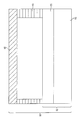
종래 EC 소자 및 설치 유리 유닛(Insulated Glass Unit, IGU)은 도 1a에 도시된 구조를 가진다. 본원에 사용된 용어 "설치 유리 유닛"은 단부를 따르는 스페이서에 의해 분리되고, 층 사이에 정체 공간(또한 그외 가스, 예컨대 아르곤, 질소, 크립톤)을 생성하도록 밀봉된 둘 이상의 유리 층을 의미한다. IGU(18)는 내부 유리 패널(10) 및 EC 소자(19)를 포함한다. EC 소자(19)는 EC 기판(12) 상에 도포되거나 침착된 일련의 막을 포함한다. 종래 EC 기판(12)은 열 강화 또는 강화 유리를 포함한다. Conventional EC elements and installed glass units (IGUs) have the structure shown in FIG. 1A. As used herein, the term "installation glass unit" means two or more glass layers separated by spacers along the ends and sealed to produce stagnant spaces (also other gases such as argon, nitrogen, krypton) between the layers. The IGU 18 includes an
IGU(18)를 형성하기 위해, EC 기판(12)이 될 유리 패널이 먼저 필요한 치수에 따라 이용 크기로 절단된다. 그 후에, 절단된 유리 패널(12)은 사용 기간(사용 로드(service load)라 함)동안 접할 수 있는 제조 응력 및 응력을 견디기에 충분한 강도를 제공하도록 강화되거나 열 강화된다. 예를 들어, 일련의 박막을 포함하는 EC 소자 스택(11)은 그 후에 이 분야에서 잘 알려진 방법(예를 들어, 이 명세서에서 참조로 포함된 자료개시인 미국 특허 제7,372,610호 및 미국 특허 제7,593,154호)에 의해 유리 패널(12)에 도포되거나 침착된다. 유리 패널(12)의 절단은 강화 또는 열 강화 후에는 수행되지 않는다. 유사하게, EC 소자의 기판(19)은 EC 스택(11)을 형성하는 막이 침전된 후에는(후 강화 EC 막 스택 및 공정을 적합하게 사용하지 않는다면) 일반적으로 강화되지 않거나 열 강화되지 않는다. 그 후에 EC 소자(19)를 또 다른 유리 패널(10)과 결합함으로써 IGU(18)가 조립된다. 두 개의 패널이 스페이서(17)에 의해 분리된다. 패널(10)은 (예를 들어, 태양 조절을 위해) 각 측면에 막 피복을 함유한다. In order to form the IGU 18, the glass panel to be the
출원인은 EC 소자 적층체를 포함하는 개선된 IGU를 개발해왔다. 출원인은 또한, 개선된 EC 소자 적층체 및 IGU를 제조하는 방법을 개발해왔다. Applicants have developed improved IGUs that include ECS device stacks. Applicants have also developed methods for manufacturing improved ECS device stacks and IGUs.
본원발명의 일 태양에서, 출원인은 전기변색 소자 적층체를 제조하는 방법을 알아냈으며, 상기 방법은 (a) 전기변색 기판을 제공하는 단계; (b) 상기 전기변색 기판을 하나 이상의 기판 도터 페인(daughter pane)으로 절단하는 단계; (c) 상기 하나 이상의 기판 도터 페인 각각 상에 복수의 전기변색 소자 전구체를 제조하는 단계; (d) 상기 전기변색 소자 전구체 각각을 개별 전기변색 소자로 절단하는 단계; 및 (e) 상기 개별 전기변색 소자를 분리된 외측 적층 유리 페인에 적층하는 단계(본원에 추가로 기재된 "절단 후, 피복 후, 절단"의 실시예)를 포함한다. 일 실시태양에서, 상기 전기변색 소자 전구체는 기계식으로 절단된다. 또 다른 실시태양에서는, 전기변색 소자 전구체가 레이터로 절단된다. 또 다른 실시태양에서는, EC 소자가 전열 절단에 의해 절단된다. In one aspect of the present invention, Applicants have found a method of making an electrochromic device laminate, the method comprising: (a) providing an electrochromic substrate; (b) cutting the electrochromic substrate into one or more substrate daughter panes; (c) fabricating a plurality of electrochromic device precursors on each of the one or more substrate daughter panes; (d) cutting each of the electrochromic device precursors into individual electrochromic devices; And (e) laminating said individual electrochromic elements to separate outer laminated glass panes (an embodiment of "after cutting, after coating, then cutting" further described herein). In one embodiment, the electrochromic device precursor is mechanically cut. In another embodiment, the electrochromic device precursor is cut with a radar. In another embodiment, the EC device is cut by electrothermal cutting.
또 다른 실시태양에서는, 개별 전기변색 소자가 약 60MPa 이상의 단부 강도를 가진다. 또 다른 실시태양에서는, 개별 전기변색 소자가 약 69MPa 이상의 단부 강도를 가진다. 또 다른 실시태양에서는, 개별 전기변색 소자가 약 75MPa 이상의 단부 강도를 가진다. 또 다른 실시태양에서는, 개별 EC 소자가 약 100MPa 이상의 단부 강도를 가진다. In yet another embodiment, the individual electrochromic devices have an end strength of at least about 60 MPa. In yet another embodiment, the individual electrochromic devices have an end strength of at least about 69 MPa. In yet another embodiment, the individual electrochromic elements have an end strength of at least about 75 MPa. In another embodiment, the individual EC devices have an end strength of at least about 100 MPa.
또 다른 실시태양에서는, 개별 전기변색 소자가 외부 적층 유리 페인과 대략 동일한 크기이다. 또 다른 실시태양에서는, 개별 전기변색 소자가 하나 이상의 치수에서 외부 적층 유리 페인보다 작다. 또 다른 실시태양에서는, 개별 전기변색 소자가 하나 이상의 치수에서 외부 적층 유리 페인에 대해 약 0.5mm 내지 약 3mm 오목하게 들어간다. 또 다른 실시태양에서는, 개별 전기변색 소자가 하나 이상의 치수에서, 바람직하게는 모든 치수에서, 외부 적층 유리 페인에 대해 약 1mm 내지 약 2.0mm 오목하게 들어간다. In another embodiment, the individual electrochromic elements are about the same size as the outer laminated glass pane. In another embodiment, the individual electrochromic elements are smaller than the outer laminated glass panes in one or more dimensions. In yet another embodiment, the individual electrochromic elements enter concave from about 0.5 mm to about 3 mm with respect to the outer laminated glass pane in one or more dimensions. In another embodiment, the individual electrochromic elements enter concave from about 1 mm to about 2.0 mm relative to the outer laminated glass pane at one or more dimensions, preferably at all dimensions.
또 다른 실시태양에서는, 전기변색 기판 및 외부 적층 유리 페인이 동일한 재료를 포함한다. 또 다른 실시태양에서는, 전기변색 기판이 외부 적층 유리 페인과 상이한 재료이다. 또 다른 실시태양에서는, 전기변색 기판을 위한 재료가 낮은 열팽창 계수 유리, 소다 석회 플로트(float) 유리, 알루미노실리케이트 유리, 보로플로트(borofloat) 유리, 보로알루미노실리케이트 유리, 기타 저 나트륨 함량 조성을 가지는 유리 또는 중합체를 포함하는 그룹으로부터 선택된다. 또 다른 실시태양에서는, 전기변색 기판이 유리 기판에 대해 약 2ppm/K 내지 약 10ppm/K 범위이고, 중합체 기판 재료에 대해서는 약 80ppm/K까지의 범위인 열팽창 계수를 가진다. 또 다른 실시태양에서는, 전기변색 기판이 약 4ppm/K 내지 약 8ppm/K 범위의 열팽창 계수를 가진다. 또 다른 실시태양에서는, 전기변색 기판이 약 0.7mm 내지 약 6mm 범위의 두께를 가진다. In another embodiment, the electrochromic substrate and the outer laminated glass pane comprise the same material. In another embodiment, the electrochromic substrate is a different material than the outer laminated glass pane. In another embodiment, the material for the electrochromic substrate has a low coefficient of thermal expansion glass, soda lime float glass, aluminosilicate glass, borofloat glass, boroaluminosilicate glass, other low sodium content compositions. Selected from the group comprising glass or polymer. In another embodiment, the electrochromic substrate has a coefficient of thermal expansion that ranges from about 2 ppm / K to about 10 ppm / K for glass substrates and up to about 80 ppm / K for polymeric substrate materials. In another embodiment, the electrochromic substrate has a coefficient of thermal expansion in the range of about 4 ppm / K to about 8 ppm / K. In another embodiment, the electrochromic substrate has a thickness in the range of about 0.7 mm to about 6 mm.
또 다른 실시태양에서는, 외부 적층 유리 페인에 대한 재료가 낮은 열팽창 계수 유리, 소다 석회 플로트 유리, 알루미노실리케이트 유리, 보로플로트 유리, 보로알루미노실리케이트 유리, 열-강화 유리, 강화 유리, 또는 중합체를 포함하는 그룹으로부터 선택된다. 또 다른 실시태양에서는, 외부 적층 유리 페인이 약 2ppm/K 내지 약 10ppm/K 범위의 열팽창 계수를 가진다. 중합체계 기판에 대한 열팽창 계수는 약 80ppm/K까지일 수 있다. 또 다른 실시태양에서는, 외부 적층 유리 페인이 약 2.3mm 내지 약 12mm 범위의 두께를 가진다. 또 다른 실시태양에서는, 중간층 재료가 폴리비닐부티랄, 이오노머 중합체, 에틸렌비닐 아세테이트, 폴리우레탄 또는 이들의 혼합물을 구성하는 그룹으로부터 선택될 수 있다. In yet another embodiment, the materials for the outer laminated glass panes may include low thermal expansion coefficient glass, soda lime float glass, aluminosilicate glass, borofloat glass, boroaluminosilicate glass, heat-reinforced glass, tempered glass, or polymers. It is selected from the group containing. In another embodiment, the outer laminated glass pane has a coefficient of thermal expansion in the range of about 2 ppm / K to about 10 ppm / K. The coefficient of thermal expansion for the polymeric substrate can be up to about 80 ppm / K. In another embodiment, the outer laminated glass pane has a thickness in the range of about 2.3 mm to about 12 mm. In another embodiment, the interlayer material can be selected from the group consisting of polyvinylbutyral, ionomer polymers, ethylenevinyl acetate, polyurethane, or mixtures thereof.
본원발명의 또 다른 태양은 "절단 후, 피복 후, 절단" 공정에 따라 제조된 적층체다. 또 다른 실시태양에서는, "절단 후, 피복 후, 절단" 공정에 따라 제조된 적층체가 약 60MPa 이상의 단부 강도를 갖는 기판을 포함한다. Another aspect of the invention is a laminate produced according to the "after cutting, after coating, after cutting" process. In another embodiment, the laminate produced according to the "after cutting, after coating, then cutting" process comprises a substrate having an end strength of at least about 60 MPa.
본원발명의 또 다른 태양으로, 출원인은 전기변색 소자 적층체를 제조하는 방법을 밝혀내었는데, 이 방법은 (a) 전기변색 기판을 제공하는 단계; (b) 상기 전기변색 기판 상에 복수의 전기변색 소자 전구체를 제조하는 단계; (c) 상기 전기변색 소자 전구체 각각을 개별 전기변색 소자로 절단하는 단계; 및 (d) 상기 개별 전기변색 소자 각각을 분리된 외부 적층 유리 페인에 적층하는 단계(본원에 추가로 기재된 "피복 후 절단"의 실시예)를 포함한다. EC 소자 전구체는 레이저 또는 전열 절단에 의해 기계식으로 절단될 수도 있다. In another aspect of the present invention, Applicants have discovered a method of making an electrochromic device laminate, the method comprising the steps of: (a) providing an electrochromic substrate; (b) preparing a plurality of electrochromic device precursors on the electrochromic substrate; (c) cutting each of the electrochromic device precursors into individual electrochromic devices; And (d) laminating each of said individual electrochromic elements onto a separate outer laminated glass pane (an embodiment of "post-coating" described further herein). The EC device precursor may be mechanically cut by laser or electrothermal cutting.
또 다른 실시태양에서는, 개별 전기변색 소자가 약 60MPa 이상의 단부 강도를 가진다. 또 다른 실시태양에서는, 단부 강도가 약 69MPa 이상이다. 또 다른 실시태양에서는, 단부 강도가 약 75MPa 이상이다. 또 다른 실시태양에서는, 단부 강도가 약 100MPa 이상이다.In yet another embodiment, the individual electrochromic devices have an end strength of at least about 60 MPa. In yet another embodiment, the end strength is at least about 69 MPa. In another embodiment, the end strength is at least about 75 MPa. In another embodiment, the end strength is at least about 100 MPa.
또 다른 실시태양에서는, 개별 전기변색 소자가 외부 적층 유리 페인과 대략 동일한 크기이다. 또 다른 실시태양에서는, 개별 전기변색 소자가 하나 이상의 치수에서 외부 적층 유리 페인보다 작다. 또 다른 실시태양에서는, 개별 전기변색 소자가 하나 이상의 치수에서 외부 적층 유리 페인에 대해 약 0.5mm 내지 약 3mm 오목하게 들어가 있다. 또 다른 실시태양에서는, 개별 전기변색 소자 하나 이상의 치수에서 외부 적층 유리 페인에 대해 약 1mm 내지 약 2.0mm 오목하게 들어가 있다. In another embodiment, the individual electrochromic elements are about the same size as the outer laminated glass pane. In another embodiment, the individual electrochromic elements are smaller than the outer laminated glass panes in one or more dimensions. In another embodiment, the individual electrochromic elements are recessed from about 0.5 mm to about 3 mm with respect to the outer laminated glass pane in one or more dimensions. In another embodiment, the individual electrochromic elements are recessed from about 1 mm to about 2.0 mm relative to the outer laminated glass pane in one or more dimensions.
또 다른 실시태양에서는, 서냉(annealed) 유리 기판 및 외부 적층 유리 페인이 동일한 재료를 포함한다. 또 다른 실시태양에서는, 전기변색 기판이 외부 적층 유리 페인과 상이한 재료이다. 또 다른 실시태양에서는, 전기변색 기판을 위한 재료가 낮은 열팽창 계수 유리, 소다 석회 플로트 유리, 알루미노실리케이트 유리, 보로플로트 유리, 보로알루미노실리케이트 유리, 저 나트륨 함량 조성을 가지는 유리, 또는 중합체를 포함하는 그룹으로부터 선택된다. 또 다른 실시태양에서는, 전기변색 기판이 약 2ppm/K 내지 약 10ppm/K 범위의 열팽창 계수를 가진다. 중합체계 기판에 대한 열팽창 계수는 약 80ppm/K까지일 수 있다. 또 다른 실시태양에서는, 전기변색 기판이 약 4ppm/K 내지 약 8ppm/K 범위의 열팽창 계수를 가진다. 또 다른 실시태양에서는, 전기변색 유리 기판은 약 0.7mm 내지 약 6mm 범위의 두께를 가진다. In another embodiment, the annealed glass substrate and the outer laminated glass pane comprise the same material. In another embodiment, the electrochromic substrate is a different material than the outer laminated glass pane. In another embodiment, the material for the electrochromic substrate comprises low thermal expansion coefficient glass, soda lime float glass, aluminosilicate glass, borofloat glass, boroaluminosilicate glass, glass with a low sodium content composition, or a polymer. Is selected from the group. In another embodiment, the electrochromic substrate has a coefficient of thermal expansion in the range of about 2 ppm / K to about 10 ppm / K. The coefficient of thermal expansion for the polymeric substrate can be up to about 80 ppm / K. In another embodiment, the electrochromic substrate has a coefficient of thermal expansion in the range of about 4 ppm / K to about 8 ppm / K. In another embodiment, the electrochromic glass substrate has a thickness in the range of about 0.7 mm to about 6 mm.
또 다른 실시태양에서는, 외부 적층 유리 페인을 위한 재료가 낮은 열팽창 계수 유리, 소다 석회 플로트 유리, 알루미노실리케이트 유리, 보로플로트 유리, 보로알루미노실리케이트 유리, 열-강화 유리, 강화 유리, 또는 중합체를 포함하는 그룹으로부터 선택된다. 또 다른 실시태양에서는, 외부 적층 유리 페인은 약 2ppm/K 내지 약 10ppm/K 범위의 열팽창 계수를 가진다. 또 다른 실시태양에서는, 외부 적층 유리 페인이 약 2.3mm 내지 약 12mm 범위의 두께를 가진다. 또 다른 실시태양에서는, 중간층 재료가 폴리비닐부티랄, 이오노머 물질, 에틸렌비닐 아세테이트, 폴리우레탄, 또는 이들의 혼합물을 포함하는 그룹으로부터 선택된다. In another embodiment, the materials for the outer laminated glass panes include low thermal expansion coefficient glass, soda lime float glass, aluminosilicate glass, borofloat glass, boroaluminosilicate glass, heat-reinforced glass, tempered glass, or polymers. It is selected from the group containing. In another embodiment, the outer laminated glass pane has a coefficient of thermal expansion in the range of about 2 ppm / K to about 10 ppm / K. In another embodiment, the outer laminated glass pane has a thickness in the range of about 2.3 mm to about 12 mm. In another embodiment, the interlayer material is selected from the group comprising polyvinylbutyral, ionomer material, ethylenevinyl acetate, polyurethane, or mixtures thereof.
본원발명의 또 다른 태양은 "피복 후, 절단" 공정에 따라 제조된 적층체다. 또 다른 실시태양에서는, 상기 피복 후, 절단 공정에 따라 제조된 적층은 약 60MPa 이상의 단부 강도를 가진 기판을 포함한다. Another aspect of the invention is a laminate made according to the "after coating, cutting" process. In another embodiment, after the coating, the laminate produced according to the cutting process comprises a substrate having an end strength of at least about 60 MPa.
본원발명의 또 다른 태양으로, 출원인은 (a) 서냉 유리 기판 상에 전기변색 스택을 포함하는 전기변색 소자; (b) 외부 적층 유리 페인; 및 (c) 전기변색 소자 및 외부 적층 유리 페인 사이에 개재된 중간층 재료를 포함하는 적층체를 고안하였다. 일부 실시태양에서, 상기 전기변색 소자는 약 60MPa 이상의 단부 강도를 가진다. 또 다른 실시태양에서는, 단부 강도가 약 69MPa 이상이다. 또 다른 실시태양에서는, 단부 강도가 약 75MPa 이상이며, 다른 실시태양에서는, 약 100MPa 이상이다. 또 다른 실시태양에서는, 전기변색 소자가 기계식 절단에 의해 제조된다. 또 다른 실시태양에서는, 전기변색 소자가 레이저 절단에 의해 제조된다. 또 다른 실시태양에서는, 전기변색 소자가 전열 절단에 의해 제조된다. 또 다른 실시태양에서는, 적층체가 집적 유리 유닛의 일부가 된다. In still another aspect of the present invention, Applicant further comprises: (a) an electrochromic device comprising an electrochromic stack on a slow cooled glass substrate; (b) outer laminated glass pane; And (c) the interlayer material interposed between the electrochromic element and the outer laminated glass pane. In some embodiments, the electrochromic device has an end strength of at least about 60 MPa. In yet another embodiment, the end strength is at least about 69 MPa. In another embodiment, the end strength is at least about 75 MPa and in other embodiments at least about 100 MPa. In another embodiment, the electrochromic device is manufactured by mechanical cutting. In another embodiment, the electrochromic device is manufactured by laser cutting. In another embodiment, the electrochromic device is manufactured by electrothermal cutting. In another embodiment, the laminate becomes part of an integrated glass unit.
또 다른 실시태양에서는, 서냉 유리 기판과 외부 적층 유리 페인이 동일한 재료를 포함한다. 또 다른 실시태양에서는, 서냉 유리 기판의 재료가 외부 적층 유리 페인과 상이한 재료이다. 또 다른 실시태양에서는, 서냉 유리 기판을 위한 재료가 낮은 열팽창 계수 유리, 소다 석회 플로트 유리, 알루미노실리케이트 유리, 보로플로트 유리, 보로알루미노실리케이트 유리, 저 나트륨 함량 조성을 가지는 유리, 또는 중합체를 포함하는 그룹으로부터 선택된다. 또 다른 실시태양에서는, 서냉 유리 기판이 약 2ppm/K 내지 약 10ppm/K 범위의 열팽창 계수를 가진다. 또 다른 실시태양에서는, 서냉 유리 기판은 약 4ppm/K 내지 약 8ppm/K 범위의 열팽창 계수를 가진다. 또 다른 실시태양에서는, 서냉 유리 페인이 약 0.7mm 내지 6mm 범위의 두께를 가진다. 또 다른 실시태양에서는, 서냉 유리 페인이 외부 적층과 동일한 두께를 가진다. 또 다른 실시태양에서는, 서냉 유리 페인이 외부 적층과 상이한 두께를 가진다. In another embodiment, the slow cooled glass substrate and the outer laminated glass pane comprise the same material. In another embodiment, the material of the slow cooled glass substrate is a different material from the outer laminated glass pane. In another embodiment, the material for the slow cooled glass substrate comprises low thermal expansion coefficient glass, soda lime float glass, aluminosilicate glass, borofloat glass, boroaluminosilicate glass, glass with a low sodium content composition, or a polymer. Is selected from the group. In another embodiment, the slow cooled glass substrate has a coefficient of thermal expansion in the range of about 2 ppm / K to about 10 ppm / K. In another embodiment, the slow cooled glass substrate has a coefficient of thermal expansion in the range of about 4 ppm / K to about 8 ppm / K. In another embodiment, the slow cooled glass pane has a thickness in the range of about 0.7 mm to 6 mm. In another embodiment, the slow cooled glass pane has the same thickness as the outer laminate. In another embodiment, the slow cooled glass pane has a different thickness than the outer laminate.
또 다른 실시태양에서는, 외부 적층 유리 페인을 위한 재료가 낮은 열팽창 계수 유리, 소다 석회 플로트 유리, 알루미노실리케이트 유리, 보로플로트 유리, 보로알루미노실리케이트 유리, 열-강화 유리, 강화 유리, 또는 중합체를 포함하는 그룹으로부터 선택된다. 또 다른 실시태양에서는, 외부 적층 유리 페인이 약 2ppm/K 내지 약 10ppm/K 범위의 열팽창 계수를 가진다. 또 다른 실시태양에서는, 중합체계 기판에 대해 열팽창 계수가 약 80ppm/K까지일 수 있다. 또 다른 실시태양에서는, 외부 적층 유리 페인이 약 2.3mm 내지 약 12mm 범위의 두께를 가진다. In another embodiment, the materials for the outer laminated glass panes include low thermal expansion coefficient glass, soda lime float glass, aluminosilicate glass, borofloat glass, boroaluminosilicate glass, heat-reinforced glass, tempered glass, or polymers. It is selected from the group containing. In another embodiment, the outer laminated glass pane has a coefficient of thermal expansion in the range of about 2 ppm / K to about 10 ppm / K. In another embodiment, the coefficient of thermal expansion may be up to about 80 ppm / K for the polymeric substrate. In another embodiment, the outer laminated glass pane has a thickness in the range of about 2.3 mm to about 12 mm.
또 다른 실시태양에서는, 서냉 유리 기판이 외부 적층 유리 페인과 대략 동일한 크기이다. 또 다른 실시태양에서는, 서냉 유리 기판이 하나 이상의 치수에서 외부 적층 유리 페인보다 작다. 또 다른 실시태양에서는, 서냉 유리 기판이 하나 이상의 치수에서 외부 적층 유리 페인에 대해 약 0.5mm 내지 약 3mm 오목하게 들어간다. 또 다른 실시태양에서는, 서냉 유리 기판이 하나 이상의 치수에서 외부 적층 유리 페인에 대해 약 1mm 내지 약 2.0mm 오목하게 들어간다. 또 다른 실시태양에서, 상기 더 작은 서냉 유리 기판의 둘레는 한 면 이상에서 중간층 재료 또는 또 다른 재료, 예컨대 실리콘, 우레탄, 에폭시, 및 아크릴레이트를 포함하는 중합체로 둘러싸인다. In another embodiment, the slow cooled glass substrate is about the same size as the outer laminated glass pane. In another embodiment, the slow cooled glass substrate is smaller than the outer laminated glass pane in one or more dimensions. In another embodiment, the slow cooled glass substrate is recessed from about 0.5 mm to about 3 mm relative to the outer laminated glass pane in one or more dimensions. In another embodiment, the slow cooled glass substrate is recessed from about 1 mm to about 2.0 mm relative to the outer laminated glass pane in one or more dimensions. In another embodiment, the perimeter of the smaller slow cooled glass substrate is surrounded on one or more sides with a polymer comprising an interlayer material or another material such as silicone, urethane, epoxy, and acrylate.
또 다른 실시태양에서는, 중간층 재료가 폴리비닐부티랄, 이오노머 물질, 에틸렌비닐 아세테이트, 폴리우레탄, 또는 이들의 혼합물을 포함하는 그룹으로부터 선택된다. In another embodiment, the interlayer material is selected from the group comprising polyvinylbutyral, ionomer material, ethylenevinyl acetate, polyurethane, or mixtures thereof.
또 다른 실시태양에서는, 상기 서냉 유리 기판이 약 8.5ppm/K의 열팽창 계수를 갖는 소다 석회 플로트 유리이고, 상기 외부 적층 유리 페인이 약 8.5ppm/K의 열팽창 계수를 가진 강화 소다 석회 플로트 유리이고, 상기 중간층 재료가 폴리비닐부티랄이다. 또 다른 실시태양에서는, 중간층 재료가 센트리글래스 ? 플러스(SentryGlas ? Plus)(SGP)이다. 또 다른 실시태양에서는, 서냉 유리 기판이 레이저 절단에 의해 제조되고, 69MPa 이상의 단부 강도를 가진다. 또 다른 실시태양에서는, 전기변색 스택이 서냉 유리 기판 및 중간층 재료 사이에 개재된다. 또 다른 실시태양에서는, 전기변색 스택이 중간층 재료에 대향하는 서냉 유리 기판의 표면 상에 있다. In another embodiment, the slow cooled glass substrate is a soda lime float glass having a coefficient of thermal expansion of about 8.5 ppm / K, the outer laminated glass pane is a tempered soda lime float glass having a coefficient of thermal expansion of about 8.5 ppm / K, The interlayer material is polyvinyl butyral. In another embodiment, the interlayer material is sentryglass? Plus (SentryGlas® Plus) (SGP). In another embodiment, the slow cooled glass substrate is manufactured by laser cutting and has an end strength of at least 69 MPa. In another embodiment, an electrochromic stack is interposed between the slow cooling glass substrate and the interlayer material. In another embodiment, the electrochromic stack is on the surface of the slow cooling glass substrate opposite the interlayer material.
본원발명의 또 다른 태양으로, 출원인은 (a) 기판 상에 전기변색 스택을 포함하는 전기변색 소자; (b) 외부 적층 유리 페인; 및 (c) 전기변색 소자 및 외부 적층 유리 페인 사이에 개재된 중간층 재료를 포함하는 적층체를 고안해내었다. 또 다른 실시태양에서는, 전기변색 소자가 레이저 절단 또는 전열 절단에 의해 제조된다.In still another aspect of the present invention, Applicant further comprises: (a) an electrochromic device comprising an electrochromic stack on a substrate; (b) outer laminated glass panes; And (c) an interlayer material interposed between the electrochromic device and the outer laminated glass pane. In another embodiment, the electrochromic device is manufactured by laser cutting or electrothermal cutting.
출원인은 예상외로 본원발명의 전기변색 소자 적층체(또는 이 적층체를 포함하는 IGU)이 강화된 또는 열처리된 유리 기판 상에서 제조된 종래 전기변색 소자(또는 그러한 종래 전기변색 소자를 포함하는 IGU)에서 생길 수 있는 것과 유사한 응력을 견딜 수 있다는 것을 밝혀내었다. 그처럼, 본원발명의 EC 소자 적층체도 그러한 유리 중심 및 단부 응력을 견딜 수 있으며, 약 17MPa 이상의 응력을 견딜 수 있다. Applicants have unexpectedly encountered a conventional electrochromic device (or IGU comprising such conventional electrochromic device) fabricated on a glass substrate that has been reinforced or heat treated with an electrochromic device stack (or IGU comprising the laminate) of the present invention. It has been found that it can withstand stresses similar to those that it can. As such, the EC device laminate of the present invention can withstand such glass center and end stresses and can withstand stresses of about 17 MPa or more.
일부 실시태양에서, 상기 유사한 응력을 견딘다는 것은 본원발명의 전기변색 소자 적층체 또는 IGU가 종래 전기변색 소자 또는 IGU와 대략 동일한 업계 표준 시험을 통과한다는 것을 의미한다. 다른 실시태양에서, 본원발명의 전기변색 소자 적층체 또는 IGU는 그러한 응력을 견딤으로써 (i) 종래 EC 응용에서 생길 수 있는 최대 가동중 열가공 응력을 문제없이 초과한 응력, 및/또는 (ii) 종래 EC 소자 또는 IGU와 동일한 응력 또는 사용 로드의 약 50% 이상을 견딜 수 있다는 것을 의미한다. 출원인은 또한 놀랍게도 이러한 목적이 전기변색 스택이 도포되거나 침착된 서냉 유리 기판을 사용하여 달성될 수 있음을 알게 되었다. In some embodiments, enduring the similar stress means that the electrochromic device stack or IGU of the present invention passes approximately the same industry standard test as the conventional electrochromic device or IGU. In other embodiments, the electrochromic device laminates or IGUs of the present invention can withstand such stresses by (i) stressing in excess of the maximum in-service thermal stresses that would occur in conventional EC applications, and / or (ii) That means it can withstand about 50% or more of the same stress or load used as conventional EC devices or IGUs. Applicants have also surprisingly found that this object can be achieved using slow cooled glass substrates to which electrochromic stacks have been applied or deposited.
출원인은 상기 개선된 제조 방법이 종래 수단에 의해 생산된 IGU에서 생길 수 있는 것과 유사한 사용 로드 또는 응력을 견딜 수 있는 전기변색 소자 적층체 또는 IGU를 제공하면서도, 예상외로 제조 효율성이 향상되고 업계 표준에 부합한다는 것을 알게 되었다. Applicants have provided electrochromic device stacks or IGUs that can withstand use loads or stresses similar to those that would occur in IGUs produced by conventional means, while unexpectedly improving manufacturing efficiency and meeting industry standards. I found out.
게다가, 출원인은 놀랍게도 서냉 유리 기판이 레이저로 절단되어, EC 소자 적층체가 그것의 사용 기간 동안 받을 수 있는 열응력 및 하중 응력의 전 범위를 견딜 수 있다고 보이는 충분히 무결함 단부를 생산할 수 있음을 밝혀내었다. 출원인은 도 1b의 그러한 레이저 절단 유리 및 EC 소자 적층체를 열응력 및 기계적 응력 파라미터 공간의 최상부에서 시험하였으며, 레이저 절단, EC 소자 적층체 또는 기판의 내구성이 높아서 거주지 및 상업 건축술 응용 및 그 외 응용의 사용에 적합하다는 것을 밝혀내었다.In addition, the Applicant has surprisingly found that slow cooled glass substrates can be laser cut to produce sufficiently flawless ends that appear to be able to withstand the full range of thermal and load stresses that an ECS stack can undergo during its service life. . Applicants have tested such laser cut glass and EC stacks of FIG. 1B at the top of the thermal stress and mechanical stress parameter space, and the durability of laser cuts, EC 적층 stacks or substrates is high for residential and commercial architecture applications and other applications. It is found to be suitable for use.
게다가, 출원인은 이 명세서에서 추가로 기술되는 "피복 후, 절단" 및 "절단 후, 피복 후, 절단" 공정 둘 다 큰 기판 패널의 피복을 가능하게 하여 피복 후 크기를 맞출 수 있음을 밝혀내었다. 출원인은 또한 이 공정이 개선된 공정 제어를 제공하여 EC 소자의 피복 막 전체가 더욱 균일할 수 있음을 밝혀내었다. 사실상, 대략 동일한 치수를 가지는 유리 패널이 사용되면, 각각의 모든 패널에 대한 후속 공정 온도 및 스퍼터링 플라스마 조건도 대략 동일할 것임을 알게 되었다. 이것은 생산을 늦추거나 멈추거나 원하는 유리 크기, 착색, 두께에 대한 조절을 처리할 필요 없이, 좀 더 효율적이고 지속적인 피복기구 또는 스퍼터링 작동을 유도한다. 따라서, 처리율 및 가동 시간이 최대화되어, 전기변색 소자 또는 IGU 제조시 더 낮고 더 경쟁적인 생산 가격을 제공하게 된다. In addition, Applicants have found that both the "post coating, cutting" and "after cutting, after coating, then cutting" processes, which are further described herein, enable the coating of large substrate panels to size after coating. Applicants have also found that this process provides improved process control so that the overall coating film of the EC device can be more uniform. In fact, it has been found that if glass panels having approximately the same dimensions are used, the subsequent process temperature and sputtering plasma conditions for each and every panel will also be approximately the same. This leads to more efficient and continuous coating or sputtering operations without the need to slow down or stop production or handle adjustments to the desired glass size, coloration and thickness. Thus, throughput and uptime are maximized, providing lower and more competitive production costs in electrochromic devices or IGU fabrication.
도 1a는 EC 소자를 포함하는 종래 IGU의 내부단면도이다.
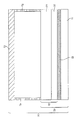
도 1b 그 자체로 두 가지 재료의 적층체인 EC 소자를 포함하는 IGU의 내부단면도이다.
도 2는 소다 석회 유리에 적층된 낮은 열팽창 유리 계수를 포함하는 EC 적층체의 응력 분포도이다.
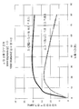
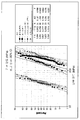
도 3a는 태양 복사에 노출된 일부 적층체에 대한 피크 단부 인장 응력을 비교한 EC 적층체의 도표이다.
도 3b는 태양 복사에 노출된 일부 적층체에 대한 피크 단부 인장 응력을 비교한 EC 적층체의 도표이다.
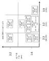
도 4는 EC 기판, EC 외부 적층 유리 페인, 및 중간층 두께의 기능을 위한 충격 시험 결과의 요약을 제공한다.
도 5는 시험 조건에 따른 레이저 절단 유리 샘플을 보여주는 4점 굽힘 시험(four-point bend test)의 일 실시예를 제공한다.
도 6은 기계식 절단 및 레이저 절단 패널을 비교하는 유리 샘플에 대한 강도의 확률도이다. 1A is an internal cross-sectional view of a conventional IGU including an EC device.
1B is an internal cross-sectional view of an IGU comprising an EC device which is itself a laminate of two materials.
2 is a stress distribution diagram of an EC laminate comprising a low coefficient of thermal expansion glass laminated on soda lime glass.
3A is a plot of EC laminates comparing peak end tensile stress for some laminates exposed to solar radiation.
3B is a plot of EC laminates comparing peak end tensile stress for some laminates exposed to solar radiation.
4 provides a summary of impact test results for the function of the EC substrate, the EC outer laminated glass pane, and the interlayer thickness.
FIG. 5 provides one example of a four-point bend test showing laser cut glass samples according to test conditions.
6 is a probability plot of strength for glass samples comparing mechanical cutting and laser cutting panels.
ECEC 소자 적층체Device stack
본원발명의 일 태양은 기판 상에 전기변색 스택을 포함하는 전기변색 소자; EC 외부 적층 유리 페인; 및 상기 전기변색 소자 및 상기 외부 적층 유리 페인 사이에 개재된 중간층 재료를 포함하는 EC 소자 적층체이다.One aspect of the present invention is an electrochromic device comprising an electrochromic stack on a substrate; EC 'external laminated glass pane; And an interlayer material interposed between the electrochromic device and the outer laminated glass pane.
EC 소자 적층체(29) 및 그것을 포함하는 IGU(30)가 도 1b에 도시되어 있다. EC 소자 적층체(29)는 EC 외부 적층 유리 페인(22)에 적층된 EC 소자(32)를 포함한다. EC 소자(32) 및 EC 외부 적층 유리 페인(22) 사이에 EC 소자(32) 및 외부 적층 페인(22)을 접합하는 중간층 재료(28)가 있다. EC 소자(32)는 그 자체로 EC 기판(31) 상에 도포되거나 침착되는 EC 스택(21)을 포함한다. 완성된 IGU(30)는 EC 소자 적층체(29) 및 스페이서(27)에 의해 분리된 또 다른 유리 패널(20)을 포함한다. 도 1b는 두 개의 페인 IGU를 나타내나, 본원발명은 또한 세 개 이상의 페인을 포함하는 IGU를 고려할 수도 있다(추가적인 페인은 이 분야에서 알려진대로 임의의 형태 또는 크기일 수도 있고, 임의의 피복, 착색 또는 그 외의 것들을 포함할 수도 있다). An EC '
임의의 EC 스택(21)이 이 분야에 통상의 기술자에게 알려진 대로 사용될 수 있다. 예시적인 EC 스택이 예를 들어, 본 명세서에서 참조로 포함되는 자료개시인 미국 특허 제5,321,544호, 미국 특허 제5,404,244호, 미국 특허 제7,372,610호, 및 미국 특허 제7,593,154에 기재되어 있다.Any
일 실시태양에서, EC 소자 적층체(29)의 하나 이상의 EC 기판(31)은 서냉 유리를 포함한다. 본원에 사용된 바대로, 용어 "서냉 유리"는 열처리 및 후속 급속 냉각에 의해 전달된 내부 응력 없이 생산된 유리를 의미한다. 이는 전형적으로 서냉 유리 또는 플로트 유리로 분류된 유리를 포함하고, 열 강화 유리 또는 강화 유리만 제외한다. In one embodiment, the at least one
다른 실시태양에서, EC 기판(31) 및 EC 외부 적층 유리 페인(22) 둘다 서냉 유리를 포함한다. EC 기판(31) 및 EC 외부 적층 유리 페인(22) 둘다 서냉 유리를 포함하는 실시태양에서, 사용된 서냉 유리는 동일("매치드(matched)"라 함)하거나 상이("미스매치드(mismatched)"라 함)할 수 있다. 사용된 서냉 유리 기판은 또한 동일하거나 상이한 열팽창 계수 또는 상이한 형태 및/또는 도펀트의 양을 가질 수도 있다. In another embodiment, both the
예를 들어, "미스매치드"의 실시태양에서, 기판(31)은 소다 석회 플로트 유리를 포함하나, EC 외부 적층 유리 페인(22)은 낮은 열팽창 계수 유리(저 CTE 유리)를 포함할 수 있으며, 또는 그 반대일 수도 있다. 일 실시예로서 "매치드" 실시태양에서는, 기판(31) 및 EC 외부 적층 유리 페인(22)은 둘다 소다 석회 플로트 유리를 포함할 수도 있고, 또는 대안으로, 둘다 저 CTE 유리를 포함할 수도 있다.For example, in an “mismatched” embodiment, the
위에서 정의한 것에 추가하여, 용어 "미스매치드"는 또한 유리 형태가 동일한지 상이한지에 상관없이 상이한 두께를 가진 유리를 사용하는 것을 의미한다. 예를 들어, 기판(31) 및 외부 적층 유리 페인(22)은 동일한 재료일 수는 있지만, 상이한 두께를 가진다. 또는, 일 실시예에 있어서, 기판(31)은 외부 적층 유리 페인(22)과 상이한 재료이면서, 상이한 두께를 가질 수 있다. 또한, 일 실시예에 있어서, 기판(31)이 외부 적층 유리 페인(22)과 동일한 형태의 재료이나 상이한 열팽창 계수 및/또는 상이한 두께를 가질 수 있다. In addition to the definitions above, the term “mismatched” also means using glass having different thicknesses, regardless of whether the glass forms are the same or different. For example, the
본원발명의 EC 기판(31)은 소다 석회 서냉 유리 예컨대, 대면적의 얇은 유리를 생산하는 가디안 인더스트리(Guardian Industries)(가디안 글로벌 헤드쿼터, 어번힐즈, 미시건(Guardian Global Headquarters, Auburn Hills, MI)), 필킹턴(Pilkington), 노쓰 아메리카(North America)(톨레도, 오하이오(Toledo, OH)), 카디널 글래스 인더스트리즈(Cardinal Glass Industries)(에덴 프레어리, 미네소타(Eden Prairie, MN)), 및 에이쥐씨(AGC)(에이쥐씨 플랫 글래스, 알파레타, GI(AGC Flat Glass, Alpharetta, GI))로부터의 것을 포함하는 종래 유리 재료로부터 선택될 수 있다. The
EC 기판(31)은 또한 저 CTE 함량의 보로플로트 유리, 예컨대 쇼트(Schott) (쇼트 노스 아메리카 엘름스포드, 뉴욕(Schott North America Elmsford, NY))로부터 입수가능한 것 또는 보로알루미노실리케이트 유리, 예컨대 코닝(Corning) 1737TM 및 코닝 이글(Corning Eagle) XGTM(각각 코닝 인코퍼레이티드, 코닝, 뉴욕(Corning Incorporated, Corning, NY)으로부터 입수 가능)를 포함하는 재료로부터 선택될 수 있다. 게다가, EC 기판(31)은 알루미노실리케이트 유리를 포함하는 재료로부터 선택될 수 있다. 이 분야에 통상의 기술자는 목적에 적합하고 청구되는 본원 발명의 제한에 부합하는 그외 유리 기판을 선택할 수 있을 것이다. The
EC 기판(31)은 또한 중합체, 공중합체 또는 하나 이상의 중합체 또는 공중합체의 혼합물을 포함할 수도 있다. 중합체의 예시로는 제한됨이 없이 폴리이미드, 폴리에틸렌 나프탈레이트(PEN), 폴리에틸렌 테레프탈레이트(PET), 아라미드 또는 기타 유사한 중합체 재료를 포함한다. 이 분야에 통상의 기술자는 목적에 적합하고 청구되는 본원 발명의 제한에 부합하는 그외 중합체 기판을 선택할 수 있을 것이다. The
일반적으로, EC 기판(31)은 원하는 응용(예를 들어, 주거 건축 창문, 상업 건축 창문, 또는 자동차 창문) 및 원하는 열/구조적 특성에 따라 임의의 두께를 가질수 있다. 전형적으로, 기판(31)은 약 0.7mm 내지 약 6mm 범위의 두께를 가진다. 일부 실시태양에서, EC 기판(31)은 약 1.5mm 내지 약 2.3mm 범위의 두께를 가진다. In general, the
일부 실시태양에서, 사용된 서냉 유리 또는 소다 석회 플로트 유리는 약 7.0ppm/K 내지 10.0ppm/K의 열팽창 계수(CTE)를 가진다. 다른 실시태양에서, 사용된 소다 석회 플로트 유리는 약 8.2ppm/K 내지 약 9.0ppm/K의 CTE를 가진다. 저 CTE 유리를 사용하는 일부 실시태양에서, 열팽창 계수의 범위는 약 2.0ppm/K 내지 약 6.4ppm/K이다. 저 CTE 유리를 사용하는 일부 특정 실시태양에서, 열팽창 계수는 코닝 1737TM(약 3.76ppm/K), 코닝 이글 XGTM(약 3.2ppm/K) 및 쇼트 보로플로트 33TM(약 3.3ppm/K)이다. In some embodiments, the slow cooled glass or soda lime float glass used has a coefficient of thermal expansion (CTE) of about 7.0 ppm / K to 10.0 ppm / K. In another embodiment, the soda lime float glass used has a CTE of about 8.2 ppm / K to about 9.0 ppm / K. In some embodiments using low CTE glass, the coefficient of thermal expansion ranges from about 2.0 ppm / K to about 6.4 ppm / K. In some specific embodiments using low CTE glass, the coefficient of thermal expansion is Corning 1737 TM (about 3.76 ppm / K), Corning Eagle XG TM (about 3.2 ppm / K) and Short Borofloat 33 TM (about 3.3 ppm / K) It is .
본원발명의 EC 외부 적층 유리 페인(22)은 열 강화 유리, 강화 유리, 부분적으로 열 강화 유리 또는 강화 유리, 또는 서냉 유리를 포함하는 재료로부터 선택될 수 있다. "열 강화 유리" 및 "강화 유리"와 같은 용어는 이 분야의 통상의 기술자에게 잘 알려진 용어이며 유리의 두 유형 다 표면 압축을 유도하고 그외 유리를 강화하기 위해 열 처리되어진다. 열처리된 유리는 완전한 강화 또는 열 강화 유리로 분류된다. 연방규격서 DD-G-1403B에 따르면, 완전한 강화 유리는 약 67 MPa 또는 그 이상의 단부 압축에 대해 약 69MPa 또는 그 이상의 표면 압축을 가져야 한다. 열 강화 유리는 약 24 내지 약 69MPa의 표면 압축을 가지거나 약 38 내지 약 67MPa의 단부 압축을 가져야 한다. 열 강화 유리의 균열 특성은 폭넓게 달라질 수 있고, 균열은 약 41부터 69MPa 이상까지 응력에서 일어날 수 있다. The EC external
일반적으로, EC 외부 적층 유리 페인(22)은 원하는 응용(예를 들어, 주거 건축 창문 또는 상업 건축 창문) 및 원하는 열/구조적 특성에 따라 임의의 두께를 가질 수 있다. 일부 실시태양에서, EC 외부 적층 페인(22)은 폴리카르보네이트를 포함하는 플라스틱을 포함할 수 있다. 전형적으로, EC 외부 적층 유리 페인(22)은 약 2.3mm 내지 약 12mm 범위의 두께를 가진다. 일부 실시태양에서, EC 외부 적층 유리 페인(22)은 약 2.3mm 내지 약 6mm 범위의 두께를 가진다. 물론, 필요한 경우, 예를 들면, 강한 풍하중을 겪는 건축 용도 또는 방탄 또는 방폭 용도로 사용되는 경우 더 두꺼운 유리가 사용될 수 있다.In general, the EC exterior laminated
일부 실시태양에서, 사용되는 서냉 유리 또는 소다 석회 플로트 유리는 약 7.0ppm/K 내지 약 10.0ppm/K의 열팽창 계수(CTE)를 가진다. 다른 실시태양에서, 소다 석회 플로트 유리는 약 8.2ppm/K 내지 약 9.0ppm/K의 CTE를 가진다. 저 CTE 유리를 사용하는 일부 실시태양에서, 열팽창 계수의 범위는 약 2.0ppm/K 내지 약 6.4ppm/K의 범위이다. 저 CTE 유리를 사용하는 일부 특정 실시태양에서, 열팽창 계수는 코닝 1737TM은 약 3.76ppm/K; 코팅 이글 XGTM는 약 3.2ppm/K; 그리고 쇼트 보로블로트 33TM은 약 3.3ppm/K와 같다. In some embodiments, the slow cooling glass or soda lime float glass used has a coefficient of thermal expansion (CTE) of about 7.0 ppm / K to about 10.0 ppm / K. In another embodiment, the soda lime float glass has a CTE of about 8.2 ppm / K to about 9.0 ppm / K. In some embodiments using low CTE glass, the coefficient of thermal expansion ranges from about 2.0 ppm / K to about 6.4 ppm / K. In some specific embodiments using low CTE glass, the coefficient of thermal expansion is about 3.76 ppm / K for Corning 1737 ™ ; Coated Eagle XG ™ was about 3.2 ppm / K; And Short Boroblot 33 TM is about 3.3 ppm / K.
일부 실시태양에서, EC 기판(31) 및 EC 외부 적층 유리 페인(22)은 대략 동일한 열팽창 계수(CTE)를 갖는다. 다른 실시태양에서, EC 기판(31) 및 EC 외부 적층 유리 페인(22)은 상이한 CTE를 가진다. 다른 실시태양에서, EC 기판(31) 및 EC 외부 적층 유리 페인(22)은 약 50% 차이나게 서로 상이한 열팽창 계수를 가진다. 그러나, 다른 실시태양에서는, EC 기판(31) 및 EC 외부 적층 유리 페인(22)이 약 30% 차이나게 서로 상이한 열팽창 계수를 가진다. 추가의 실시태양에서, EC 기판(31) 및 EC 외부 적층 유리 페인(22)은 약 20% 차이나게 서로 상이한 열팽창 계수를 가진다. 또 다른 실시태양에서는, EC 기판(31) 및 EC 외부 적층 유리 페인(22)이 약 10% 차이나게 서로 상이한 열팽창 계수를 가진다. 본원에 기재된 것처럼, 적절한 중간층 재료(28)의 선택이 CTE 미스매치드에 의해 일어나는 임의의 응력을 경감시키는데 도움이 될 수 있다. In some embodiments, the
예를 들어, 도 2는 저 CTE 유리가 EC 기판(31)으로 사용되고, 소다 석회 유리 EC 외부 적층 페인(22)으로 사용되고, 폴리비닐부티랄이 중간층 재료(28)로 사용되는 경우의 적층체의 응력 분포를 도시하고 있다. 시뮬레이션은 상기 패널의 단부 주변의 25mm 프레임의 음영 효과를 보여주고 있다. 그 프레임은 적층체의 단부 및 중심 사이의 온도 변화 때문이며, 이로써, 단부 응력의 형성의 원인이 됨을 알 수 있다. 적층 구조의 경우에, CTE 미스매치드는 태양 흡수가 상기 소자를 데우는 원인이 되는 것처럼, 추가적인 응력의 원인이 된다. 이 CTE 미스매치드의 효과는 도 3a에 도시되어 있다. 여기서, 1000W/m2 입사 방사선의 조건으로 태양 흡수 저 CTE/소다 석회 유리 적층체는 도 3a에서 도시된 동일한 태양 흡수 조건에서 소다 석회/소다 석회 적층 구조와 비교하여 더 높은 피크 응력 레벨을 가진다. 이 실시예에서 보여지는 것처럼, 최대 단부 응력은 EC 적층체가 약 40분 후에 약 20.5MPa의 최대 응력에까지 더 많은 태양 복사를 흡수하는 만큼 시간을 거쳐 변화한다. 더 오랜 시간에서, 노출된 영역으로부터 음영의 단부 영역까지의 유리를 통한 열 전도는 온도가 평형을 유지하도록 하고 대응하는 열응력이 그 피크 레벨로부터 감소되도록 할 것이다. 이 응력은 예컨대, 도 3a의 조건과 동일한 단부 프레임 음영 및 태양 흡수 조건인 도 3b에서 보는 바와 같이, 두 개의 저 CTE 패널이 함께 적층될 때, 감소될 수 있는 것으로 보인다.For example, FIG. 2 shows a laminate in which low CTE glass is used as the
바람직한 실시태양에서, EC 기판(31)의 단부는 수동적 및 기계적 손상으로부터 보호된다. 임의의 특정 이론에 구속되기를 바라지는 않지만, EC 기판(31)의 단부에 크게 흠집이 나거나 깨지면, EC 소자의 전체 강도가 절충될 것으로 보인다. 본원발명의 일부 실시태양에서, EC 기판(31)은 EC 외부 적층 유리 페인(22)에 대해 오목하게 들어간다. 다른 실시태양에서, EC 기판(31)의 크기가 하나 이상의 치수, 바람직하게는 둘 이상의 치수, 및 더욱 바람직하게는 모든 치수에서 EC 외부 적층 유리 페인(22)의 크기보다 조금 더 작다. 일부 실시태양에서, EC 기판(31)은 유리 페인(22)에 대해, 하나 이상의 치수에서 약 0.5mm 내지 약 3mm, 및 바람직하게는 둘레 주위로 약 0.5mm 내지 약 3mm 오목하게 들어간다. 다른 실시태양에서, EC 기판(31)은 유리 페인(22)에 대해, 하나 이상의 치수에서 약 1mm 내지 약 2.0mm, 및 바람직하게는 둘레 주위로 약 1 mm 내지 약 2.0mm 오목하게 들어간다. In a preferred embodiment, the ends of the
일부 실시태양에서, 오목한 깊이는 역 적층 공정 동안 일어나는 임의의 작은 움직임에 더하여 적층 레이업/제조 공정 동안 두 조각의 유리의 자동 설치 내성에 의해 결정된다. 일부 실시태양에서, 열처리 동안 중간층 재료는, 수송 및 설치 동안에 EC 소자 적층체(29)를 더 보호하는 보호 요소를 제공하는 EC 기판(31)의 단부 주변을 흐르게 된다. 일부 실시태양에서, 과도한 중간층 재료가 이를 달성하기 위해 더해진다. 다른 실시태양에서, 추가의 보호 재료가 EC 소자 예컨대 중합체(이에 제한되는 것은 아니지만 에폭시, 우레탄, 실리콘, 및 아크릴레이트를 포함함)의 둘레 주위에 침착될 수 있다. 이 재료는 원하는 결과를 달성하기 위해 다양한 양으로 도포될 수 있다. In some embodiments, the concave depth is determined by the automatic installation resistance of the two pieces of glass during the lamination layup / manufacturing process in addition to any small movements that occur during the reverse lamination process. In some embodiments, the intermediate layer material during heat treatment flows around the ends of the EC '
중간층 재료는 이 분야에서 잘 알려진 방법으로 EC 소자(32)를 EC 외부 적층 유리 페인(22)에 적층되게 하는 임의의 재료로부터 선택될 수 있다. 일반적으로, 중간층 재료(28)는 (a) 고 광투명도; (b) 저 헤이즈(haze); (c) 고 충격저항성; (d) 고 관입저항성; (e) 자외선저항성; (f) 양호한 장기 열안정성; (g) 유리 및/또는 그외 중합체 재료/시트에 충분한 접착력; (h) 저 흡습력; (i) 고 습기저항력; (j) 훌륭한 내후성; 및 (k) 고 응력하중 저항력(예를 들어, 충격하중 또는 풍하중)을 포함하는 특성의 조합을 가져야 한다. 일부 실시태양에서, 중간층 재료(28)는 적어도 EC 소자(32) 및 EC 외부 적층 유리 페인(22) 둘다에 충분한 접착력을 제공하여 사용시 응력 하중을 받을 동안 박리를 막고, 또한, EC 소자 적층체(29)의 시각적 특성에 부정적인 영향을 끼치지 않도록 선택된다. 다른 실시태양에서, 중간층 재료는 업계 표준 요구 성능이 하중 모드 둘다(예를 들어, 충격 테스트에 대해 ANSI Z97.1 및 풍하중 요구에 대해 ASTM E1300)에 만족되도록 선택되어야 한다. The interlayer material can be selected from any material that allows the
일 실시태양에서, 적합한 중간층 재료(28)는 사플렉스(Saflex)TM이라는 상품명으로 솔루시아 인코퍼레이티드(Solutia Inc.)(세인트루이스, 미주리(St. Louis, Missouri))로부터 입수 가능한 폴리비닐부티랄(PVB)이다. PVB는 또한 부타사이트(ButaciteTM)라는 상품명으로 듀퐁(DuPont)(윌밍턴, 델라웨어(Wilmington, DE))로부터 입수 가능하다. 중간층 재료(28)를 위해 그외 적합한 재료는 이오노머 물질, 예컨대 듀퐁의 센트리글래스 플러스TM(SGP), 에틸렌비닐 아세테이트(EVA) 및 가교결합 폴리우레탄 (예를 들면, 캐스트-인-플레이스(cast-in-place) 수지) 또는 열가소성 폴리우레탄을 포함한다. 물론, 상기 재료의 임의의 혼합물이 사용될 수도 있다. 게다가, 그외 중합체 재료는 상기 언급된 열가공, 접착, 및 광투명 기능 조건의 일부 또는 전부를 만족하도록 제공되는 중간층 재료(28)로 사용될 수 있다. 이는 또한 개선된 음감쇠, 방탄 및 방폭 용도를 위해 디자인된 복합 중합체 층으로 구성된 중간층 재료를 포함한다. 이 재료는 이 분야에 통상의 기술자에게 손쉽게 사용될 수 있는 것들이다.In one embodiment, a
다른 실시태양에서, 중간층 재료(28)는 실리콘 및 에폭시를 포함할 수 있다.In other embodiments, the
예를 들어, 만약 EC 기판(31) 및 EC 외부 적층 유리 페인(22)이 동일한 재료를 포함한다면, 유리 패널 둘다 대략 동일한 열팽창 계수를 가짐이 틀림없다. 재료가 다르다면, 즉, 임의의 특정 이론에 구속되기를 바라지는 않지만, 도 2와 같은 미스매치드의 경우, 적절한 중간층 재료(28)의 선택이 미스매치드 유리 패널들 사이의 응력의 분배 또는 이동에 영향을 줄 것임이 틀림없으므로, 적층체의 다양한 지점에 존재하는 응력의 일부 또는 전부가 경감된다고 여겨진다. For example, if the
유리 페인들 사이에 미스매치드 열팽창 계수(CTE)를 포함하는 적층 구조에 있어서, 중간층이 (1) 고 CTE 유리 패널로부터 저 CTE 유리 패널로 인장 응력을 충분히 이동시키지 않도록 하거나, (2) 저온도에서 사소한 중합체 기계 릴렉세이션으로 냉각하는 동안 압축 응력이 고 CTE 유리 패널로부터 저 CTE 유리 패널로 이동되도록 적층 온도로부터 충분히 딱딱하도록 선택되어야 한다. In a laminated structure comprising mismatched coefficient of thermal expansion (CTE) between glass panes, the interlayer is (1) thin and does not sufficiently transfer the tensile stress from the CTE glass panel to the low CTE glass panel, or (2) It should be chosen to be hard enough from the lamination temperature so that the compressive stress is transferred from the high CTE glass panel to the low CTE glass panel during cooling with a minor polymer mechanical relaxation at.
도 3a 및 3b는 1" 창문/건축 프레임에 음영된 단부를 가지고, 태양 복사에 노출된 적층체(이 경우에 구성요소 패널들은 각각 0.7mm 및 6mm의 두께를 가짐)에 대한 피크 단부 인장 강도의 비교를 제공한다. 매치드(저 CTE/저 CTE; 소다 석회/소다 석회) 및 미스매치드(저 CTE/소다 석회)에 대한 실시예가 시간의 기능으로 보여진다. 딱딱한 중간층 재료(응력 이동력)에 대해, 저 CTE/소다 석회 조합의 실질적인 응력은 소다 석회/소다 석회 조합의 응력보다 더 클 수도 있다. 그처럼, 단부 응력의 결과는 중간층 재료의 열가공 특성에 달려있을수 있음이 틀림없다. 3A and 3B show the peak end tensile strength for a laminate exposed to solar radiation, in which case the component panels have a thickness of 0.7 mm and 6 mm, respectively, with a shaded end in a 1 "window / architectural frame. Examples are provided as a function of time for matched (low CTE / low CTE; soda lime / soda lime) and mismatched (low CTE / soda lime). For, the substantial stress of the low CTE / soda lime combination may be greater than the stress of the soda lime / soda lime combination As such, the results of the end stress must depend on the thermal processing properties of the interlayer material.
EC 소자 적층체(29)(또는 이 적층체를 포함하는 IGU(30))는 강화 또는 열처리 유리 기판상에 제조되는 종래 전기변색 소자(또는 그러한 종래 전기변색 소자를 포함하는 IGU)에 의해 생길수 있는 것과 유사한 응력을 견딜수 있다. The EC element stack 29 (or
일부 실시태양에서, 그 유사한 응력을 견딘다는 것은 본원발명의 EC 소자 적층체(29) 또는 IGU(30)가 종래 전기변색 소자 또는 IGU와 동일한 업계 표준 시험을 통과한다는 것을 의미한다. 다른 실시태양에서, 그 유사한 응력을 견딘다는 것은 (i) 종래 EC 응용에서 생길 수 있는 최대 가동중 열가공 응력을 문제없이 초과한 응력, 및/또는 (ii) 종래 전기변색 소자 또는 IGU와 동일한 응력 또는 사용 로드의 약 50% 이상을 견딜 수 있다는 것을 의미한다. 일부 실시태양에서, EC 소자 적층체(29)는 약 17 MPa 이상의 열 단부 응력(또는 사용 로드)를 견딜 수 있다. 다른 실시태양에서, EC 소자 적층체는 약 21MPa 이상의 열 단부 응력을 견딜 수 있다. 일부 실시태양에서, EC 소자(29)는 약 60MPa 이상의 단부 강도를 가진다. 또 다른 실시태양에서, EC 소자 또는 EC 기판 약 69MPa 이상의 단부 강도를 가진다. 또 다른 실시태양에서는, EC 소자 또는 EC 기판이 약 75MPa 이상의 단부 강도를 가진다. 또 다른 실시태양에서, EC 소자 또는 EC 기판은 약 100MPa 이상의 단부 강도를 가진다.In some embodiments, withstanding similar stresses means that the EC '
일부 실시태양에서, EC 적층체(29) 또는 EC 기판(31)이 IGU의 일부이다. IGU를 형성하도록 사용되는 유리 패널(20)은 종래 IGU에서 사용된 유리 또는 플라스틱을 포함하는 임의의 재료로부터 선택되어도 좋다. 예를 들어, 임의의 종류의 유리(소다 석회 유리, 저 CTE 유리, 강화 유리, 및/또는 서냉 유리) 또는 플라스틱이 사용되어도 좋다. 게다가, 유리 패널(20)은 그 자체로 하나 이상의 재료(다중 페인 유리, 다중 페인 플라스틱, 임의의 순서로 번갈아 있는 유리, 플라스틱 페인)의 다중 페인 적층체일 수 있다. 유리 패널(20)은 또한 임의의 종래 방식, 예컨대 화학증착법(CVD) 또는 물리증착법으로 한면 또는 양쪽면에 피복되거나 임의의 색으로 착색될 수 있다. 유리 패널(20)은 전기변색 또는 열변색 소자가 될 수 있다. 유리 패널(20)은 레이저로 절단될 수도 있고 기계식으로 스크라이빙(scribe)될 수도 있다. 게다가, 도 1b의 IGU(30)는 삼중 IGU, 예를 들어 스페이서에 의해 분리되나, 유리 패널(20) 또는 EC 소자 적층체(29) 중 하나에 인접하여 추가의 유리(또는 중합체, 예를 들어. 아크릴) 패널(20)을 포함하는 삼중 IGU가 될 수도 있다. 유리 패널(20)은 상업 또는 주거 빌딩 코드 및/또는 창문 기준에 최소한 부합하는 임의의 특성 또는 임의의 두께를 가질 수 있다. In some embodiments, the
제조 방법Manufacturing method
"" 피복covering 후, after, 절section 단only ""
본원발명에서 제시된 일실시예에서, 출원인은 '피복 후, 절단' 개념을 포함하는 제조 방법을 밝혀내었다. 본원발명의 일 태양은 전기변색 기판을 포함하는 전기변색 소자 적층체를 제공하는 단계; 기판 상에 복수의 전기변색 소자 전구체를 제조하는 단계; 전기변색 소자 전구체 각각을 개별 전기변색 소자로 절단하는 단계; 및 개별 전기변색 소자 각각을 분리된 외부 적층 유리 페인에 적층하는 단계를 포함하는 전기변색 소자 적층체를 제조하는 방법이다. 본원에 사용된 바대로, "전기변색 소자 전구체"는 상기 언급된것처럼 기판을 개별적인 EC 소자로 절단하기 전에 기판 상에 도포되거나 침착되는 박막의 전형적인 스택, EC 소자이다. 그처럼, 다중 EC 소자 전구체는 임의의 하나의 기판 상에 제조되거나, 또는 본원에 기재된 것처럼 기판 도터 페인 상에 제조된다. 전형적으로, EC 전구체 배치는 일반적으로 임의의 막들 또는 스택에 손상 없이 바람직하게 절단되도록 하기 위해, 전구체들 사이의 충분한 공간을 포함하도록 설계된다. In one embodiment presented in the present invention, Applicant has discovered a manufacturing method that includes the concept of 'after coating, cutting'. One aspect of the invention provides an electrochromic device stack comprising an electrochromic substrate; Preparing a plurality of electrochromic device precursors on a substrate; Cutting each electrochromic device precursor into individual electrochromic devices; And laminating each individual electrochromic device onto a separate outer laminated glass pane. As used herein, an "electrochromic device precursor" is a typical stack of EC 'devices, as described above, deposited or deposited on a substrate before cutting the substrate into individual EC' devices. As such, multiple EC device precursors are prepared on any one substrate, or on the substrate daughter pane as described herein. Typically, the EC precursor batch is generally designed to include sufficient space between the precursors so that any films or stacks are preferably cut without damage.
일부 실시태양에서, 일반적으로 EC 소자(32)(또는 전구체)가 큰 기판 패널(31), 예컨대 서냉 유리 상에 EC 스택(21)을 피복하거나 도포하여 생산된다. 스택은 본원에 포함된 바대로 이 분야에 잘 알려진 방법에 따라 도포되거나 침착되어도 좋다. 후속하여, EC 소자(32)(또는 전구체)는 최종 응용에 따라 원하는 치수로 절단된다(본원에 상세히 기재된, 종래 기계식 수단, 레이저 절단법, 또는 전열 절단법에 의해). 물론, 패널은 임의의 크기 또는 형태로 절단되어도 좋다. 기판은 또한 더 큰 패널로부터 미리 절단되어 있을수도 있다. 그후, 소자(32)는 바람직하게는 추가의 기계 강도를 제공하기 위해 EC 외부 적층 유리 페인(22)에 적층된다. EC 적층체(29)는 도 1b에 도시된 바와 같이 EC 소자 기판(32)으로 구성될 수 있다(EC 적층체(29)의 외부 상에 EC 막 스택(21)을 가짐). 또는, 대안으로, EC 적층체(29)는 중간층 재료(28)에 접촉한 EC 막 스택(21)(예를 들어, 적층체 내부에 EC 막 스택)으로 맞추어진 EC 소자 기판(32)으로 구성될 수 있다. In some embodiments, the EC element 32 (or precursor) is generally produced by coating or applying the
일단 EC 소자 적층체(29)가 처리되면, IGU(30)를 형성하기 위해 선택적으로 유리(20)와 조합될 수 있다. Once the
일부 실시태양에서, EC 외부 적층 유리 페인은 대략 EC 소자와 동일한 크기이다. 다른 실시태양에서, EC 외부 적층 유리 페인은 EC 소자와 상이한 크기이다. 일부 실시태양에서, 상기 언급한 바와 같이, EC 기판은 외부 유리 페인에 대해 오목하게 들어가 있다. 본원에 추가로 언급한 바와 같이, EC 외부 적층 유리는 EC 소자(또는 EC 소자가 침착된 기판)와 대략 동일하거나 상이한 두께 및/또는 열팽창을 가질 수 있다. 외부 적층 유리 페인은 기계식으로 절단되거나 레이저로 절단된다. 본원발명의 또 다른 태양은 이 방법에 따라 제조된 적층체이다.In some embodiments, the EC outer laminated glass pane is approximately the same size as the EC element. In another embodiment, the EC 'outer laminated glass pane is of a different size than the EC' element. In some embodiments, as mentioned above, the EC 'substrate is recessed with respect to the outer glass pane. As further mentioned herein, the EC'outer laminated glass may have a thickness and / or thermal expansion that is about the same or different than the EC element (or the substrate on which the EC element is deposited). The outer laminated glass panes are mechanically cut or laser cut. Another aspect of the present invention is a laminate made according to this method.
"" 절단 후,After cutting, 피복covering 후, after, 절section 단only ""
제시된 본원발명의 또 다른 실시태양에서, 출원인은 상기 언급된 방법인 '피복 후, 절단'을 적용하는 것에 이어, 먼저 EC 기판의 큰 패널을 하나 이상의 기판 도터 패널로, 예컨대 하나 이상의 기판 도터 패널 각각으로 절단(이 공정을 이하 "절단 후, 피복 후, 절단" 공정이라 함)하는 단계를 포함하는 제조 방법을 밝혀내었다. In another embodiment of the present invention presented, the Applicant, following the application of the aforementioned method of 'after coating, cutting', first converts a large panel of EC substrates into one or more substrate daughter panels, such as one or more substrate daughter panels, respectively. The production method was found to include a step of cutting (hereinafter, referred to as "cutting, then coating, cutting" process).
이처럼, 본원발명의 또 다른 태양은 전기변색 기판을 포함하는 전기변색 소자 적층체를 제공하는 단계; 전기변색 기판을 하나 이상의기판 도터 패널로 절단하는 단계; 복수의 전기변색 소자 전구체를 하나 이상의 기판 도터 패널 각각에 제조하는 단계; 전기변색 소자 전구체 각각을 개별 전기변색 소자로 절단하는 단계; 및 개별 전기변색 소자 각각을 분리된 외부 적층 유리 페인 상에 적층하는 단계를 포함하는 전기변색 소자 적층체의 제조 방법이다. As such, another aspect of the present invention provides an electrochromic device stack comprising an electrochromic substrate; Cutting the electrochromic substrate into one or more substrate daughter panels; Fabricating a plurality of electrochromic device precursors into each of the one or more substrate daughter panels; Cutting each electrochromic device precursor into individual electrochromic devices; And laminating each individual electrochromic device onto a separate outer laminated glass pane.
일부 실시태양에서, 서냉 유리의 큰 기판 패널은 하나 이상의 기판 도터 패널로 절단된다. 다른 실시태양에서, 서냉 유리의 큰 기판 패널은 복수의 기판 도터 패널로 절단된다. 기판 도터 패널 각각은 대략 동일한 크기 및/또는 형태이거나, 상이한 크기 및/또는 형태일 수도 있다. 예를 들어, 최초의 큰 EC 기판은 세 개의 동일한 크기의 기판 도터 패널로 절단되거나 각각 상이한 크기를 지닌 세 개의 기판 도터 패널로 절단될 수도 있다. 그 후, 기판 도터 패널 단부의 일부 또는 전부는 선택적인 단부 연마 공정, 바람직하게는 세척에 의해 따르는 연마 공정을 실시해도 좋다. 다른 실시태양에서, 큰 기판 패널 하나의 더 작은(하나 이상의 치수로) 기판 도터 패널로 절단된다.In some embodiments, the large substrate panel of slow cooled glass is cut into one or more substrate daughter panels. In another embodiment, a large substrate panel of slow cooled glass is cut into a plurality of substrate daughter panels. Each of the substrate daughter panels may be approximately the same size and / or shape, or may be different sizes and / or shapes. For example, the first large EC substrate may be cut into three equally sized substrate daughter panels or three substrate daughter panels each having a different size. Thereafter, part or all of the end portion of the substrate daughter panel may be subjected to an optional end polishing process, preferably a polishing process followed by washing. In other embodiments, one large substrate panel is cut into one smaller (in one or more dimensions) substrate daughter panel.
일부 실시태양에서, 본원에 기재된 바대로, 기판 도터 패널은 추가의 처리, 예를 들어, EC 스택을 가진 기판 도터 패널 각각을 피복하여 EC 소자 전구체를 제조하는 처리를 위한 수송체로 적하된다. 임의의 수의 기판 도터 패널이 임의의 하나의 수송체로 적하될 수 있으나, 가능한 많은 기판 도터 패널이 맞도록 수송체의 표면 면적을 최적하하는 것이 바람직하다. 그 후, 기판 도터 패널 각각 상의 EC 소자 전구체 각각은 예컨대 레이저 또는 전열 절단, 또는 기계식 수단에 의해 절단된다. In some embodiments, as described herein, the substrate daughter panel is loaded with a carrier for further processing, for example, coating each of the substrate daughter panels with an EC stack to produce an EC element precursor. Any number of substrate daughter panels may be loaded with any one carrier, but it is desirable to optimize the surface area of the vehicle to fit as many substrate daughter panels as possible. Thereafter, each of the EC element precursors on each of the substrate daughter panels is cut, for example, by laser or electrothermal cutting, or mechanical means.
절단 후, 피복 후, 절단 공정은 다음의 몇 가지 장점을 제공함이 틀림없다. 첫째로, 유리 기판이 스퍼터링 공정 동안의 미세한 각도(보통 수직에 대해 약 5도 및 9도)에 유지됨이 일반적이다. 이 각도는 유리를 구부러지게 하여 최종적으로 불균일한 피복을 발생시킬 수 있는 편차를 일으킬 수 있다. 유리의 크기가 증가되는 만큼 유리의 구부러짐도 증가됨이 틀림없다. 이처럼, 먼저 더 큰 기판 패널로부터 잘려진 더 작은 조각의 유리 상의 스퍼터링을 통한 도포된 피복(예를 들어, EC 스택)은 임의의 잠재된 불균일성을 완화시키는데 도움이 될 것이다. 일부 실시태양에서, 기판 유리는 피복동안 수직으로 유지된다. 임의의 특정 이론에 구속되기를 바라지는 않지만, 상기 구부러짐은 열응력에 의해서도 유발될 수 있다고 여겨진다. 임의의 열응력은 유사하게 기판 도터 패널, 바람직하게는 더 작은 기판 도터 패널을 사용함으로 감소될 수 있음이 틀림없다. After cutting, after coating, the cutting process must provide several advantages: First, it is common for the glass substrate to be maintained at a fine angle (usually about 5 degrees and 9 degrees with respect to the vertical) during the sputtering process. This angle can cause deviations that can cause the glass to bend and ultimately produce an uneven coating. As the size of the glass increases, the bending of the glass must also increase. As such, an applied coating (eg, EC stack) through sputtering on a smaller piece of glass, first cut from a larger substrate panel, will help mitigate any potential nonuniformity. In some embodiments, the substrate glass remains vertical during coating. While not wishing to be bound by any particular theory, it is believed that the bending can also be caused by thermal stress. Any thermal stress must similarly be reduced by using a substrate daughter panel, preferably a smaller substrate daughter panel.
둘째로, 언제나 제조사로부터 원하는 특정 기판 유리 크기(또는 형태)가 가능할 수는 없다. 예를 들어, 제조사로부터 원하는 유리가 너무 커거 수송체 또는 활성 스퍼터링 챔버에 맞지 않을 수도 있다. 게다가, 더 큰 조각의 유리를 구입하여 먼저 수송체에 맞게 그것들을 절단하게 되면 더욱 효율적인 비용을 소비할 수 있다.Second, the specific substrate glass size (or shape) desired from the manufacturer may not always be possible. For example, the glass desired from the manufacturer may be too large to fit the vehicle or active sputtering chamber. In addition, purchasing larger pieces of glass and cutting them first for the vehicle can consume more efficient costs.
셋째로, 받은 유리의 단부가 항상 즉각적인 처리에 적합한 조건에 있을수 없음이 틀림없다. 이 경우에, 먼저 유리를 무결점 단부 또는 제조 및 처리 조건에 부합하는 단부를 가진 더 작은 도터 패널로 절단하는 것이 바람직하다. Third, the end of the glass received must always be in a condition suitable for immediate processing. In this case, it is preferable to first cut the glass into smaller daughter panels having a flawless end or an end meeting the manufacturing and processing conditions.
넷째로, 임의의 큰 유리 조각은 결점을 가질 수 있다. 많은 양의 유리 또는 처리 시간을 소비함이 없이, 큰 유리 패널로부터 결점 없는 유리 패널이 절단될 수 있다. Fourth, any large piece of glass can have drawbacks. Flawless glass panels can be cut from large glass panels without consuming large amounts of glass or processing time.
"피복 후, 절단" 및 "절단 후, 피복 후, 절단" 공정에서 적층 단계는 이 분야의 통상의 기술자에게 잘 알려진 방법을 사용하여 수행된다. 예를 들어, 전형적인 적층 공정은 유리 패널들 사이의 부분적 접합을 생성하도록 중간 압력에서 적층체를 가열하는 공정, 예를 들면, 닙 롤러(nip roller) 공정, 및 후속되는 승온 및 승압 하, 예를 들면, 오토클레이브를 사용한 연장 결합 공정에 의해 유리에의 결합을 완성하고 잔여 공기를 제거하거나 또는 공기를 중합체 구조내로 용해시켜 광학적으로 투명한 중간층을 생성하는 단계를 포함한다. 다른 접근 방법은 (i) 공기를 중간층 영역으로부터 제거하고 유리 패널을 결합하기 위한 가열 공정과 결합된 진공 공정, 또는 (ii) 투명한 중간층을 생성하기 위해 모세관 공간을 충전하는 유리 패널 사이의 갭에 부어지는 중합체를 사용한다.Lamination steps in the "after coating, cutting" and "after cutting, after coating, cutting" processes are carried out using methods well known to those skilled in the art. For example, a typical lamination process is a process of heating a laminate at an intermediate pressure to create a partial bond between glass panels, such as a nip roller process, and subsequent elevated temperature and elevated pressure, for example. For example, an extension bonding process using an autoclave may be used to complete bonding to the glass and remove residual air or dissolve the air into the polymer structure to produce an optically clear intermediate layer. Another approach is to (i) vacuum process combined with a heating process to remove air from the interlayer region and join the glass panels, or (ii) pour into the gap between the glass panels filling the capillary space to create a transparent interlayer. Losing polymers.
통상적인 기계식 Conventional mechanical 스크라이빙Scribing (( scribescribe )) 또는 절단 Or cutting
전형적인 유리 제조는 카바이드 또는 다이아몬드 팁 스크라이빙 또는 휠(wheel)을 사용하여 유리 패널의 표면 상에 절단을 생성한 후, 단부를 따라 표면 크랙을 전파하기 위해 휨 모멘트를 적용하여 직선 절단이라 믿어지는 절단을 생성하는 것을 포함한다. 유리의 단부는 종종 그라인더 또는 실리콘 카바이드 샌딩(sanding) 벨트를 사용하여 갈아진다.Typical glass making is believed to be a straight cut using carbide or diamond tip scribing or wheels to create a cut on the surface of the glass panel and then applying a bending moment to propagate the surface cracks along the ends. Generating a cleavage. The ends of the glass are often ground using a grinder or silicon carbide sanding belt.
레이저 절단Laser cutting
본원발명의 일부 실시태양에서, 레이저가 EC 소자 적층체(29) 또는 EC 기판(31)을 절단하는데 사용된다. 본원에서 사용된 용어 "레이저 절단"은 (i) 레이저를 사용하여 기판 표면에 수직으로 얇은 크랙을 생성한 후, 이를 휨 모멘트의 적용에 의해 유리를 통해 전파하여 완전한 분리를 생성하는 것, 또는 (ii) 기판의 길이 방향을 따라 전파되는 레이저-유도된 크랙에 의해 유리를 통한 절단을 완성하여 분리를 완성하는 것을 의미한다. 레이저 절단 공정은 "피복 후, 절단" 및 "절단 후, 피복 후, 절단" 공정에 동등하게 적용될 수 있다.In some embodiments of the present invention, a laser is used to cut the EC '
따라서, 본원발명의 일 태양은 전기변색 기판을 제공하는 단계; 복수의 전기변색 소자 전구체를 기판 상에서 제조하는 단계; 각각의 전기변색 소자 전구체를 개별 전기변색 소자로 레이저 절단하는 단계; 및 개별 전기변색 소자 각각을 적층하여 외부 적층 유리 페인을 분리하는 단계를 포함하는 전기변색 소자 적층체의 제조 방법이다. 일부 실시태양에서, 레이저 절단 공정은, 얇은 표면 크랙을 유도한 후, 휨 모멘트의 적용에 의한 전파를 통해 분리에 이르는 공정, 또는 후속 휨 또는 "브레이크아웃"이 요구되지 않고, 크랙을 발생시키고 기판을 따라 전파시키는 것에 의해 분리를 완성시키는 완성된 "절단-관통(cut-through)"을 포함한다.Accordingly, one aspect of the present invention provides a method for producing an electrochromic substrate; Preparing a plurality of electrochromic device precursors on a substrate; Laser cutting each electrochromic device precursor into a separate electrochromic device; And laminating each of the individual electrochromic devices to separate the outer laminated glass panes. In some embodiments, the laser cutting process does not require a process to induce thin surface cracks and then to separation through propagation by application of a bending moment, or subsequent warpage or "breakout", and generates cracks and substrates. And complete “cut-through” to complete the separation by propagating along.
보다 구체적으로, 열적으로 강하고 혁신적인 적층된 외부 판유리는 집중된 레이저 빔을 사용하여 피복된 유리 기판을 각각의 도터 페인으로 절단하는 것을 가능하게 하는 것에 의해 제조된다. 어떤 특정 이론에 구속되는 것을 바라지는 않지만, 레이저 에너지가 유리를 국소적으로 가열한 후 분리 선을 따라 신속한 냉각이 이루어진다고 믿어진다. 이는 유리에 수직인 방향으로 크랙이 형성되는 것을 야기하며, 이로써 각각 오염 및 단부 약화를 초래할 수 있는 부스러기 또는 부가적인 미세 크랙이 존재하지 않는 단부를 형성한다. 생성되는 레이저 공정에 의한 단부는 어떠한 부가적인 단부 마감 공정을 요구하지 않는다.More specifically, thermally strong and innovative laminated outer panes are produced by making it possible to cut the coated glass substrate into individual daughter panes using a focused laser beam. While not wishing to be bound by any particular theory, it is believed that laser energy causes rapid cooling along the separation line after local heating of the glass. This causes cracks to form in a direction perpendicular to the glass, thereby forming ends where there are no debris or additional fine cracks that can result in contamination and end weakness, respectively. The resulting laser process does not require any additional end finishing process.
일부 실시태양에서, 레이저 절단 단부는 표준 기계 절단된 단부에 비해 약 두 배 내지 약 세 배 높은 응력에 견딜 수 있다고 믿어지는데, 이는 열-강화 유리에 비교할 만한 단부 강도라 여겨진다. 따라서, 레이저 절단된 비강화 EC 소자 기판은 유리가 많이 착색될 때 전형적으로 발생하는 온도 변화, 및 이러한 온도 변화와 관련된 응력에 견딜 수 있다고 믿어진다.In some embodiments, it is believed that the laser cut end can withstand about two to about three times higher stress than the standard machine cut end, which is considered an end strength comparable to heat-reinforced glass. Therefore, it is believed that laser cut unreinforced EC device substrates can withstand the temperature changes typically occur when the glass is heavily colored, and the stresses associated with such temperature changes.
일부 실시태양에서, 레이저 절단 패널은 약 60MPa 이상의 응력에 견딜 수 있다. 다른 실시태양에서, 레이저 절단 패널은 약 69MPa 이상의 응력에 견딜 수 있다. 또 다른 실시태양에서, 레이저 절단 패널은 약 75MPa 이상의 응력에 견딜 수 있다. 또 다른 실시태양에서, 레이저 절단 패널은 약 100MPa 이상의 응력에 견딜 수 있다. 또 다른 실시태양에서, 레이저 절단 패널은 약 70MPa 내지 약 310MPa의 응력에 견딜 수 있다..In some embodiments, the laser cutting panel can withstand a stress of about 60 MPa or more. In other embodiments, the laser cutting panel can withstand a stress of about 69 MPa or more. In yet another embodiment, the laser cutting panel can withstand a stress of about 75 MPa or more. In another embodiment, the laser cutting panel can withstand a stress of at least about 100 MPa. In another embodiment, the laser cutting panel can withstand a stress of about 70 MPa to about 310 MPa.
전열 절단Electrothermal cutting
본원발명의 일부 실시태양에서, 전열 절단(ETC)이 ED 소자 적층체(20) 또는 EC 기판(31)을 절단 또는 분리하는데 사용된다. ETC는 절연 또는 반도체 기판 내의 작은 영역의 가열(및 필요하면, 증발) 방법을 의미한다. 일부 실시태양에서, 유리는 두 개의 전극 사이의 AC 방전의 적용에 의해 절단된다. 어떤 특정 이론에 구속되길 바라진 않지만, 높은 전압이 유리를 국소적으로 가열하고 냉각 헤드가 적합한 응력을 생성하여 관통 크랙을 생성한다고 믿어진다. 전극/냉각 헤드 조립체는 그 후 제한된 경로를 통해 이동하여, 요구되는 EC 기판 또는 EC 기판 도터 패널의 관습적인 크기로 형성된 원하는 패턴으로 크랙(조절된 분리)을 전파시킨다.In some embodiments of the present invention, electrothermal cutting (ETC) is used to cut or separate the
일부 실시태양에서, ETC에 의해 절단된 패널은 레이저에 의해 절단된 것과 유사한 응력에 견딜 수 있다. 다른 실시태양에서, ETC에 의해 절단된 패널은 약 60 MPa 이상의 응력에 견딜 수 있다. 또 다른 실시태양에서, ETC에 의해 절단된 패널은 약 69 MPa 이상의 응력에 견딜 수 있다. 또 다른 실시태양에서, ETC에 의해 절단된 패널은 약 75 MPa 이상의 응력에 견딜 수 있다. 또 다른 실시태양에서, ETC에 의해 절단된 패널은 약 80 MPa 이상의 응력에 견딜 수 있다. 또 다른 실시태양에서, ETC에 의해 절단된 패널은 약 100 MPa 이상의 응력에 견딜 수 있다.In some embodiments, the panel cut by the ETC can withstand stresses similar to those cut by the laser. In another embodiment, the panel cut by the ETC can withstand a stress of at least about 60 MPa. In another embodiment, the panel cut by the ETC can withstand a stress of about 69 kPa MPa or more. In another embodiment, the panel cut by the ETC can withstand a stress of at least about 75 MPa. In another embodiment, the panel cut by the ETC can withstand a stress of at least about 80 kPa MPa. In another embodiment, the panel cut by the ETC can withstand a stress of about 100 Pa MPa or more.
실험 데이터 및 실시예Experimental Data and Examples
적층체 충격 시험 결과Laminate Impact Test Results
도 4에 도시된 바와 같이, (1) 서냉 소다 석회 플로트 유리 또는 저-CTE 유리로 구성된 EC 기판(31); 및 (2) 열 강화 유리, 강화 유리, 또는 서냉 유리를 포함하는 EC 외부 적층 유리 페인(22)을 포함하는 "미스매치드(mismatched)" 적층체 상에서 충격 시험을 수행하였다. 충격 데이터는 EC 기판(31) 및 EC 외부 적층 유리 페인(22)의 두께에 관한 유용한 디자인의 창문을 제시하였다. 폴리비닐부티랄(PVB) 및 이오노머 중합체(듀퐁의 SGP)를 중간층 재료(28)로서 시험하였다. SGP는 PVB에 비해 EC 기판/지지 기판 및 중간층 두께에 관한 보다 좁은 디자인의 창문을 보여주었는데, 어떤 특정 이론에 구속되기를 바라지는 않지만, PVB의 보다 양호한 성능은 PVB 재료의 증강된 순응도/연신도와 관련된다고 믿어진다.As shown in Fig. 4, (1) an
도 4는 EC 기판(31), EC 외부 적층 유리 페인(22) 및 중간층(28) 두께의 함수로서의 충격 시험 데이터를 요약하고 있다. 도 4는 EC 기판(31) 두께, EC 외부 적층 유리 페인(22) 두께 및 중간층 재료(28) 두께의 상이한 조합들을 보여주고 있다. ANSI Z97.1-2004에 의해 요구되는 34" x 76" 시험 크기에 대해, 데이터는 넓은 범위의 유리 및 중간층 두께에 걸친 용도를 제시하였다. PVB는 유리 및 중간층 두께에 관해 보다 견고하다고 믿어진다.4 summarizes impact test data as a function of the thickness of the
적층 판유리에 대한 시험 표준으로 가장 널리 참조되는 것은 미국 표준 협회의 표준 ANSI Z97.1-2004(건물에 사용하기 위한 안전 판유리 재료에 대한 미국 ㅍ표준 - 안전 성능 사양 시험 방법)이다. 이 표준은 건물 및 건축 목적으로 사용되는 안전 판유리 재료에 대한 사양 및 시험 방법 둘 다를 확립하였다. 시험은 테더의 끝에 매달려 있으며 적층 유리 패널의 중심선으로 흔들리는 100 파운드의 납 샷(shot) 자루의 충격을 포함한다. 소비자 제품 안전 위원회(CPSC)에서 발생된 추가의 표준인 16CFR1201이 있는데, 이는 동일한 시험 방법에 의하지만, 통과/실패 기준이 약간 상이하다.The most widely referenced test standard for laminated panes is the American National Standards Institute standard ANSI Z97.1-2004 (American Standard for Safety Plate Materials for Building Use-Safety Performance Specification Test Method). This standard established both specifications and test methods for safety pane materials used for building and construction purposes. The test included the impact of a 100 pound lead shot bag hanging from the tip of the tether and swaying to the centerline of the laminated glass panel. There is an additional standard, 16CFR1201, generated by the Consumer Product Safety Commission (CPSC), which follows the same test method, but with slightly different pass / fail criteria.
Z97.1 및 16CFR1201 시험에 대한 통과/실패 기준은 약간 상이하다. Z97.1 시험은 파손 및 3-인치 직경의 볼이 통과할 수 있는 것보다 작은 크기의 인열/구멍의 형성을 허용한다. 16CFR1201 시험은 추가적으로 패널이 수평 위치에 있을 때 무게 4 파운드의 3-인치 볼이 1초 후 개구를 통해 떨어지지 않을 것을 요구한다. 보고된 통과/실패 데이터는 Z97.1 기준에 근거한 것이지만, 적층체의 강도는 16CFR1201에 대해서도 통과될 것으로 믿어진다.The pass / fail criteria for the Z97.1 and 16CFR1201 tests are slightly different. The Z97.1 test allows breakage and the formation of tears / holes of a smaller size than the three-inch diameter ball can pass through. The 16CFR1201 test additionally requires that a 4-inch ball weighing 4 pounds will not fall through the opening after 1 second when the panel is in the horizontal position. The reported pass / fail data is based on the Z97.1 criterion, but it is believed that the strength of the laminate will also pass for 16 CFR1201.
양 실험 모두 자루가 떨어지는 높이에 따라 상이한 카테고리를 각진다. 48"의 높이로부터의 낙하(400 피트-파운드)를 포함하는 가장 극단적인 시험으로부터의 결과를 제시하였다. 전형적인 시험 패널 크기는 34" x 76"이지만, 다른 크기(40" x 40")에 대해서도 시험하였다. 40" x 40" 크기는 보다 도전적인 시험을 나타낸다. 이하의 실시예 1 내지 8의 충격 시험용 유리 기판은 기계 스크라이빙(scribing)에 의해 절단하였다. 시험은 미네소타주 파리볼트의 세이지(SAGE) 및 위스콘신 주의 아메리의 카디날엘쥐(CardinalLG)에서 수행하였다.Both experiments angle different categories according to the height at which the bag falls. Results are presented from the most extreme test, including a drop from a height of 48 "(400 feet-pounds). Typical test panel size is 34" x 76 ", but for other sizes (40" x 40 "). 40 "
실시예:Example:
실시예Example 1 - One - ECEC 적층체Laminate
CTE: 8.5ppm/KThickness: 3.2mm
CTE: 8.5 ppm / K
CTE: 8.5ppm/KThickness: 1.7mm
CTE: 8.5 ppm / K
제조 방법:Manufacturing method:
실시예 1의 적층 EC 구조를 "절단 후, 피복" 공정에 따라 제조하였다. 적층은 통상적인 닙 롤러/오토클레이브 공정을 사용하여 수행하였다. 진공 적층 공정에 의해 동등한 결과를 얻을 수 있었다.The laminated EC structure of Example 1 was prepared according to the "after cutting, coating" process. Lamination was carried out using conventional nip roller / autoclave processes. Equivalent results were obtained by the vacuum lamination process.
결과:result:
상기 기재한 구성성분을 가지는 적층 EC 구조는 충격 시험에 관한 ANSI Z97.1 표준을 통과하였다.The laminated EC structure with the components described above passed the ANSI Z97.1 standard for impact testing.
실시예Example 2 - 2 - ECEC 적층체Laminate
CTE: 8.5ppm/KThickness: 4mm
CTE: 8.5 ppm / K
CTE: 8.5ppm/KThickness: 1.7mm
CTE: 8.5 ppm / K
제조 방법:Manufacturing method:
실시예 2의 적층 EC 구조를 "절단 후, 피복" 공정에 따라 제조하였다. 적층은 통상적인 닙 롤러/오토클레이브 공정을 사용하여 수행하였다. The laminated EC structure of Example 2 was prepared according to the "After Cutting, Coating" process. Lamination was carried out using conventional nip roller / autoclave processes.
결과:result:
상기 기재한 구성성분을 가지는 적층 EC 구조는 충격 시험에 관한 ANSI Z97.1 표준을 통과하였다.The laminated EC structure with the components described above passed the ANSI Z97.1 standard for impact testing.
상이한 두께를 가지는 외부 적층 패널을 실시예 1 및 2에서, 수득된 충격 시험을 모두 통과한 적층체를 사용하여 시험하였다. 진공 적층 공정에 의해 동등한 결과를 얻을 수 있었다.External laminated panels with different thicknesses were tested using the laminates which passed all of the impact tests obtained in Examples 1 and 2. Equivalent results were obtained by the vacuum lamination process.
실시예Example 3 - 3 - ECEC 적층체Laminate
CTE: 8.5ppm/KThickness: 3.2mm
CTE: 8.5 ppm / K
CTE: 8.5ppm/KThickness: 1.7mm
CTE: 8.5 ppm / K
제조 방법:Manufacturing method:
실시예 3의 적층 EC 구조를 "절단 후, 피복" 공정에 따라 제조하였다. 적층은 통상적인 닙 롤러/오토클레이브 공정을 사용하여 수행하였다. The laminated EC structure of Example 3 was prepared according to the "After Cutting, Coating" process. Lamination was carried out using conventional nip roller / autoclave processes.
결과:result:
상기 기재한 구성성분을 가지는 적층 EC 구조는 충격 시험에 관한 ANSI Z97.1 표준을 통과하였다. 진공 적층 공정에 의해 동등한 결과를 얻을 수 있었다.The laminated EC structure with the components described above passed the ANSI Z97.1 standard for impact testing. Equivalent results were obtained by the vacuum lamination process.
실시예Example 4 - 4 - ECEC 적층체Laminate
CTE: 8.5ppm/KThickness: 4mm
CTE: 8.5 ppm / K
CTE: 8.5ppm/KThickness: 1.7mm
CTE: 8.5 ppm / K
제조 방법:Manufacturing method:
실시예 4의 적층 EC 구조를 "절단 후, 피복" 공정에 따라 제조하였다. 적층은 통상적인 닙 롤러/오토클레이브 공정을 사용하여 수행하였다. The laminated EC structure of Example 4 was prepared according to the "After Cutting, Coating" process. Lamination was carried out using conventional nip roller / autoclave processes.
결과:result:
상기 기재한 구성성분을 가지는 적층 EC 구조는 충격 시험에 관한 ANSI Z97.1 표준을 통과하였다.The laminated EC structure with the components described above passed the ANSI Z97.1 standard for impact testing.
상이한 두께를 가지는 외부 적층 패널을 실시예 3 및 4에서, 수득된 충격 시험을 모두 통과한 적층체를 사용하여 시험하였다. 진공 적층 공정에 의해 동등한 결과를 얻을 수 있었다.External laminated panels having different thicknesses were tested using the laminates which passed all of the impact tests obtained in Examples 3 and 4. Equivalent results were obtained by the vacuum lamination process.
실시예Example 5 - 5 - ECEC 적층체Laminate
CTE: 8.5ppm/KThickness: 4mm
CTE: 8.5 ppm / K
CTE: 3.3ppm/KThickness: 1.7mm
CTE: 3.3 ppm / K
제조 방법:Manufacturing method:
실시예 5의 적층 EC 구조를 "절단 후, 피복" 공정에 따라 제조하였다. 적층은 통상적인 닙 롤러/오토클레이브 공정을 사용하여 수행하였다. The laminated EC structure of Example 5 was prepared according to the "after cutting, coating" process. Lamination was carried out using conventional nip roller / autoclave processes.
결과:result:
상기 기재한 구성성분을 가지는 적층 EC 구조는 충격 시험에 관한 ANSI Z97.1 표준을 통과하였다. 진공 적층 공정에 의해 동등한 결과를 얻을 수 있었다.The laminated EC structure with the components described above passed the ANSI Z97.1 standard for impact testing. Equivalent results were obtained by the vacuum lamination process.
실시예Example 6 - 6 - ECEC 적층체Laminate
CTE: 8.5ppm/KThickness: 2.3mm
CTE: 8.5 ppm / K
CTE: 8.5ppm/KThickness: 1.7mm
CTE: 8.5 ppm / K
제조 방법:Manufacturing method:
실시예 6의 적층 EC 구조를 "절단 후, 피복" 공정에 따라 제조하였다. 적층은 통상적인 닙 롤러/오토클레이브 공정을 사용하여 수행하였다. The laminated EC structure of Example 6 was prepared according to the "after cutting, coating" process. Lamination was carried out using conventional nip roller / autoclave processes.
결과:result:
상기 기재한 구성성분을 가지는 적층 EC 구조는 충격 시험에 관한 ANSI Z97.1 표준을 통과하였다. 진공 적층 공정에 의해 동등한 결과를 얻을 수 있었다.The laminated EC structure with the components described above passed the ANSI Z97.1 standard for impact testing. Equivalent results were obtained by the vacuum lamination process.
실시예Example 7 - 7 - ECEC 적층체Laminate
CTE: 8.5ppm/KThickness: 2.3mm
CTE: 8.5 ppm / K
CTE: 8.5ppm/KThickness: 1.7mm
CTE: 8.5 ppm / K
제조 방법:Manufacturing method:
실시예 7의 적층 EC 구조를 "절단 후, 피복" 공정에 따라 제조하였다. 적층은 통상적인 닙 롤러/오토클레이브 공정을 사용하여 수행하였다. The laminated EC structure of Example 7 was prepared according to the "After Cutting, Coating" process. Lamination was carried out using conventional nip roller / autoclave processes.
결과:result:
상기 기재한 구성성분을 가지는 적층 EC 구조는 충격 시험에 관한 ANSI Z97.1 표준을 통과하였다. 진공 적층 공정에 의해 동등한 결과를 얻을 수 있었다.The laminated EC structure with the components described above passed the ANSI Z97.1 standard for impact testing. Equivalent results were obtained by the vacuum lamination process.
실시예Example 8 - 8 - 세이지글래스Sage glass (( SageGlassSageglass )? )? ECEC 소자 device
CTE: 8.5ppm/KThickness: 6mm
CTE: 8.5 ppm / K
CTE: 8.5ppm/KThickness: 6mm
CTE: 8.5 ppm / K
제조 방법:Manufacturing method:
실시예 8의 IGU를 본원에 기재된 표준 제조 방법에 따라 제조하였다.The IGU of Example 8 was prepared according to the standard manufacturing methods described herein.
결과:result:
상기 기재한 구성성분을 가지는 IGU는 충격 시험에 관한 ANSI Z97.1 표준을 통과하였다.The IGU with the components described above passed the ANSI Z97.1 standard for impact testing.
실시예 1 내지 7의 적층 IGU 및 실시예 8의 전통적인 IGU는 모두 충격 시험에 관한 ANSI Z97.1을 통과한 것으로 관찰되었다. 따라서, 본원발명의 EC 소자 적층체(및 그를 포함하는 IGU)는 건축 용도에 대한 모둔 중요한 산업 기계적 성능 요건을 충족/초과할 수 있는 것으로 믿어진다.Both the laminated IGUs of Examples 1-7 and the traditional IGUs of Example 8 were observed to pass ANSI Z97.1 for impact testing. Accordingly, it is believed that the EC device stacks (and IGUs comprising them) of the present invention can meet / exceed all important industrial mechanical performance requirements for building applications.
기계식으로Mechanically 스크라이빙된Scribed 서냉Slow cooling , 레이저 절단 Laser cutting 서냉Slow cooling 및 열-강화 소다 석회 And heat-reinforced soda lime 플로트pontoon 유리 Glass 단부End 강도의 비교 Comparison of strength
다양한 유리 조성, 기판 두께 및 기계적 시험 샘플 방향에 대해 레이저 절단 단부 강도를 평가하였다. 레이저 절단 유리에 대한 단부 강도의 가장 좋은 정량적 측정은 4점 굽힘 시험 셋업을 사용하여 수행하였다. 4점 굽힘에서, 도 5에 도시된 '누워 있는(lying down)' 샘플 방향을 사용한 예에서, 내부 스팬 하의 모든 영역에 동일한 휨 모멘트가 가해졌고, 따라서 보다 큰 효과적인 영역에 대한 정보가 얻어질 수 있다고 믿어졌다. '단부-상(edge-on)' 및 '누운' 방향 모두에서의 단부 강도를 시험하였다. '단부-상' 방향이 처음에 사용되었는데, 이는 그것이 서비스 되는 것과 유사한 응력 조건에서 상부 및 바닥 단부 모두를 동시에 시험하는 것을 가능하게 하기 때문이다. 그러나, 양 시험 방향 모두에서 뛰어나게 일치하는 데이터를 얻었고, '누운' 방향이 통상적인 4점 굽힘 시험 고정 기기를 사용하여 보다 용이하게 시험할 수 있기 때문에, 대부분의 시험 샘플을 '누운' 방향에서 시험하였다. 전형적인 샘플 크기는 25mm 폭 및 330mm 길이였고, 효과적인 시험 영역은 약 100mm였다. 다양한 유리 두께(약 1mm 내지 2.3mm의 범위), 및 다양한 제조원으로부터의 표준 소다 석회 플로트 유리 및 이글2000TM 및 이글XGTM(코닝 제조) 및 보로플로트33TM(쇼트 글래스 제조)을 포함하는 유리 조성에 대해 시험하였다.Laser cut end strengths were evaluated for various glass compositions, substrate thicknesses, and mechanical test sample orientations. The best quantitative measurements of end strength for the laser cut glass were performed using a four point bend test setup. In a four-point bend, in the example using the 'lying down' sample direction shown in Fig. 5, the same bending moment was applied to all areas under the inner span, so that information about larger effective areas could be obtained. It was believed that End strength was tested in both 'edge-on' and 'lying' directions. The 'end-up' direction was initially used because it makes it possible to simultaneously test both the top and bottom ends under stress conditions similar to those serviced. However, most test samples were tested in the 'laid' direction because excellent data were obtained in both test directions and the 'laid' direction could be more easily tested using a conventional four-point bend test fixture. It was. Typical sample sizes were 25 mm wide and 330 mm long and the effective test area was about 100 mm. Various glass thicknesses (range from about 1 mm to 2.3 mm), and glass compositions including standard soda lime float glass and Eagle2000 ™ and EagleXG ™ (manufactured by Corning) and Borofloat33 ™ (manufactured by Short Glass) from various manufacturers Was tested against.
본원의 소다 석회 유리에 관한 레이저 절단 단부 강도 데이터와 서냉, 열 강화 및 완전 강화 소다 석회 유리에 대한 단부 강도 문헌 값을 비교하였다. 피어(Veer) 등은 서냉, 열 강화 및 강화 유리를 비교한 종합적인 실험 연구서를 최근 발행하였다(문헌[Veer, FA, PC Louter and FP Bos, " The strength of annealed , heat-strengthened and fully tempered float glass," Fatigue & Fracture of Engineering Materials & Structures, 32 pp.18-25 (2009)]). 열-강화 또는 강화와 관련된 최소 크기의 제한때문에, 샘플 크기(10 x 100 x 1000mm, 약 500mm의 유효 시험 길이)는 본원의 연구에서 보다 매우 컸으며, 직접 비교를 위해서는 적절한 비례 축소가 필요했는데, 이는, 통계적으로 말하자면, 보다 넓은 면적이 주어진 응력에서 의미있는 크기의 흠을 가질 가능성이 높기 때문이다. 문헌[Vuolio (2003) and Beason and Lignell (2002) Beason, WL and AW Lignell, "A Thermal Stress Evaluation Procedure for Monolithic Annealed Glass", Symp . on Use of Glass in Buildings , ASTM STP1434, ed. VL Block (2002)]에 기재된 작업에 기초하여 처리하였는데, 이에 따르면 상이한 샘플 크기에 대한 강도는 각각의 단부 영역의 비율에 비례한다:The laser cut end strength data for soda lime glass herein is compared with the end strength literature values for slow cooling, thermally strengthened and fully tempered soda lime glass. Peer et al. Recently published a comprehensive experimental study comparing slow cooling, heat strengthening and tempered glass (Veer, FA, PC Louter and FP Bos, " The strength of annealed , heat-strengthened and fully tempered float glass, " Fatigue & Fracture of Engineering Materials & Structures , 32 pp. 18-25 (2009)]. Due to the minimum size limitations associated with heat-reinforcement or reinforcement, the sample size (10 x 100 x 1000 mm, effective test length of about 500 mm) was much larger than in our study, and a proper proportional reduction was needed for direct comparison. This is because, statistically speaking, larger areas are more likely to have significant sized flaws at a given stress. Vuolio (2003) and Beason and Lignell (2002) Beason , WL and AW Lignell, "A Thermal Stress Evaluation Procedure for Monolithic Annealed Glass ", Symp . On Use of Glass in Buildings , ASTM STP1434, ed. VL Block (2002), based on the work described, whereby the intensity for different sample sizes is proportional to the proportion of each end region:
σ1/σ2 = (면적2/면적1)1/m σ 1 / σ 2 = (area 2 / area 1 ) 1 / m
바이불(Weibull) 계수 m은 각각의 강도 분포에서의 변화의 정도이다. 실험 데이터로부터 측정된 m의 값인 5.8을 보정을 위해 사용하였다. 이는 비율 1.7에 해당한다.The Weibull coefficient m is the degree of change in each intensity distribution. To calibrate 5.8, the value of m measured from the experimental data, Respectively. This corresponds to ratio 1.7.
내부(in-house) 및 문헌 시험 결과를 비교한 면적-조정 데이터를 도 6에 도시하였다. 내부 및 문헌 데이터의 비교는 레이저 절단 시험 데이터가 열-강화("HS") 및 완전 강화("FT") 문헌 데이트에 대한 분포 사이에 위치한다는 점을 시사하였다.Area-adjusted data comparing in-house and literature test results is shown in FIG. 6. Comparison of the internal and literature data suggested that the laser cutting test data was located between the distributions for heat-enhanced ("HS") and full-enhanced ("FT") literature data.
도 6은 추가로 기계식 및 레이저 스크라이빙에 대한 단부 강도의 비교 확률도를 도시한다. 레이저 스크라이빙된 패널은 60 MPa 이상의 강도를 보이는 것으로 믿어진다. 일부 실시태양에서, 레이저 스크라이빙된 패널의 강도는 69 MPa 이상, 바람직하게는 약 75 MPa 이상, 보다 바람직하게는 약 100 MPa 이상이었다.6 further shows a comparative probability plot of end strengths for mechanical and laser scribing. Laser scribed panels are believed to exhibit strengths of at least 60 kPa MPa. In some embodiments, the intensity of the laser scribed panel was at least 69 MPa, preferably at least about 75 MPa, more preferably at least about 100 MPa.
도 6은 또한 실험적 시험(기계식("기계식 스크라이빙") 및 ("레이저 절단") 및 문헌 데이터(시험 샘플 크기의 차이에 대해 조정된))의 비교를 제공한다. 통상적인 기계식 스크라이빙 및 레이저 절단 공정을 사용하여 제조한 서냉 샘플에 대한 시험 데이터는 도 6에서 각각 삼각형 및 정사각형으로 도시되어 있다. 일반적으로, 레이저-절단 유리의 강도 분포(상이한 레이저 절단 기계를 사용한 5개의 상이한 레이저 절단 작업으로부터 얻은 전체 데이터를 표시)는 HS와 FT 성능 사이의 성능을 가진다고 기술할 수 있다.6 also provides a comparison of experimental tests (mechanical ("mechanical scribing") and ("laser cutting") and literature data (adjusted for differences in test sample size)). Test data for slow cooling samples prepared using conventional mechanical scribing and laser cutting processes are shown in FIG. 6 as triangles and squares, respectively. In general, it can be described that the intensity distribution of the laser-cut glass (indicating the total data obtained from five different laser cutting operations using different laser cutting machines) has a performance between HS and FT performance.
실시예Example 9 - 레이저-절단 9-laser cutting 적층체Laminate
CTE: 8.5ppm/KThickness: 3.2mm
CTE: 8.5 ppm / K
CTE: 8.5ppm/KThickness: 1.7mm
CTE: 8.5 ppm / K
제조 방법:Manufacturing method:
실시예 9의 레이저-절단 적층체를 "피복 후, 절단" 공정에 따라 제조하였다. 적층은 통상적인 닙 롤러/오토클레이브 공정을 사용하여 수행하였다. EC 스택을 침착시킨 후, 본원에 기재한 바와 같이 EC 기판(EC 소자 또는 소자 전구체)를 레이저 절단하였다. 레이저-절단 적층체 단부 강도를 샘플 내 온도 구배의 형성에 의한 단부 응력을 유도하는 것에 의해 측정하였다. 온도 구배는 적층체에 비해 측면 크기가 작은 실리콘 가열 패드를 사용하여 형성하였다. 패드를 약 25mm 폭의 비가열 주변을 가지는 적층체의 표면 상에 위치시켰다. 구배의 크기를 인가된 힘을 가열 패드에 맞추는 것에 의해 조정하였으며(베리악(variac) 가변 전원 공급기에 의해 조정됨), 이때 적층체 단부는 거의 실온으로 유지하였다. 유도된 온도 구배에 의해 형성된 단부 응력은 광탄성 기술(위스콘신주 메이슨의 스트레스 포토닉스 인코포레이티드(Stress Photonics, Inc.))을 사용하여 직접 측정하였다.The laser-cut laminate of Example 9 was prepared according to the "after coating, cutting" process. Lamination was carried out using conventional nip roller / autoclave processes. After depositing the EC stack, the EC substrate (EC device or device precursor) was laser cut as described herein. The laser-cut laminate end strength was measured by inducing end K forces by the formation of a temperature gradient in the sample. The temperature gradient was formed using silicon heating pads with smaller side dimensions compared to the laminate. The pad was placed on the surface of the laminate having a non-heated perimeter of about 25 mm wide. The size of the gradient was adjusted by fitting the applied force to the heating pad (adjusted by a variac variable power supply), with the laminate ends maintained at approximately room temperature. End stresses formed by induced temperature gradients were measured directly using photoelastic techniques (Stress Photonics, Inc., Mason, Wisconsin).
결과:result:
상기 기재된 구성성분을 가지는 레이저-절단 적층 EC 구조는 적층 후 약 60MPa 이상의 단부 강도를 가졌다.The laser-cut laminated EC structure with the components described above had an end strength of at least about 60 MPa after lamination.
제조된 열적 에이저 스크라이빙(TLS) 가공의 공정 성능 연구를 또한 수행하였다. 연구에서는 앞서 기재한 기계적, 4점 굽힘 시험을 사용하였다. 5개의 시험 세션으로부터의 80개 초과의 샘플로부터 얻은 데이터를 수집하였다. 6개월이 기간에 걸친 5개의 상이한 TLS 작업을 나타내는 데이터를 상이한 최대 서비스 내(in-service) 단부 강도에 기초한 공정 성능을 개발하는데 사용하였다. 공정 성능 Cpk는 제조된 강도가 EC 소자 적층체 창문 용도에 대한 작동 응력 환경에서의 실패의 가능성을 낮추기에 충분하다는 것을 시사하였다.Process performance studies of the prepared thermal aging scribe (TLS) processing were also performed. The study used the mechanical, four-point bend test described previously. Data from more than 80 samples from five test sessions was collected. Data representing five different TLS jobs over a six month period was used to develop process performance based on different maximum in-service end strengths. Process performance Cpk suggested that the strength produced was sufficient to reduce the likelihood of failure in operating stress environments for EC device laminate window applications.
통상적인 통계학적 방법을 사용하여 공정 성능을 계산하기 위해, 데이터는 정규 분포를 가질 것이 요구되었다. TLS 기계적 시험 데이터는 로그 정규 분포를 따랐으며 정규 분포를 얻기 위해 대수 변환이 필요하였다. 공정 성능 값 및 상응하는 예측 실패 비율을 다수의 보다 낮은 사양 한계(즉, 최대 단부 응력)에 대해 계산하여 소자 열 구배에 대한 민감도를 측정하였다. 최대 단부 응력은 환경 상호작용 및 창문 및 건축 프레임 디자인(예를 들면, 완전 절연된 프레임 대 열 흡수 디자인)에 의존하였다. 성능 분석은 미니탭15(Minitab15) 통계학 소프트웨어 페키지를 사용하여 계산하였다.In order to calculate process performance using conventional statistical methods, the data was required to have a normal distribution. TLS mechanical test data followed a lognormal distribution and an algebraic transformation was required to obtain a normal distribution. Process performance values and corresponding predictive failure rates were calculated for a number of lower specification limits (ie, maximum end stresses) to determine the sensitivity to device thermal gradients. Maximum end stresses depended on environmental interactions and window and building frame design (eg, fully insulated frame to heat absorption design). Performance analysis was calculated using the
본원발명이 특정 실시태양들을 참조하여 기술되었지만, 이들 실시태양들은 단순히 본원발명의 원리 및 용도의 예시일 뿐이라는 점이 이해되어야 한다. 따라서, 이들 예시적인 실시태양에 수많은 변경이 가해질 수 있다는 점 및 특허청구범위에 기재된 본원발명의 범위를 벗어나지 않으면서 다른 태양들이 고안될 수 있다는 점이 이해되어야 한다.Although the invention has been described with reference to specific embodiments, it should be understood that these embodiments are merely illustrative of the principles and uses of the invention. Accordingly, it should be understood that numerous modifications may be made to these exemplary embodiments and that other aspects may be devised without departing from the scope of the invention as set forth in the claims.
Claims (77)
(b) 상기 전기변색 기판을 하나 이상의 기판 도터 페인(daughter pane)으로 절단하는 단계;
(c) 상기 하나 이상의 기판 도터 페인 각각 상에 복수의 전기변색 소자 전구체를 제조하는 단계;
(d) 상기 복수의 전기변색 소자 전구체 각각을 개별 전기변색 소자로 절단하는 단계; 및
(e) 상기 개별 전기변색 소자 각각을 분리된 외측 적층 유리 페인에 적층하는 단계
를 포함하는, 전기변색 소자 적층체의 제조 방법.(a) providing an electrochromic substrate;
(b) cutting the electrochromic substrate into one or more substrate daughter panes;
(c) fabricating a plurality of electrochromic device precursors on each of the one or more substrate daughter panes;
(d) cutting each of the plurality of electrochromic device precursors into individual electrochromic devices; And
(e) laminating each of said individual electrochromic elements onto a separate outer laminated glass pane
A manufacturing method of an electrochromic device laminate comprising a.
상기 복수의 전기변색 소자 전구체 각각은 기계식으로 절단되는, 방법. The method of claim 1,
Wherein each of the plurality of electrochromic device precursors is mechanically cut.
상기 복수의 전기변색 소자 전구체 각각은 레이저로 절단되는, 방법.The method of claim 1,
Wherein each of the plurality of electrochromic device precursors is cut with a laser.
상기 복수의 전기변색 소자 전구체 각각은 전열 절단에 의해 절단되는, 방법.The method of claim 1,
Wherein each of the plurality of electrochromic device precursors is cut by electrothermal cutting.
상기 개별 전기변색 소자 각각은 약 60MPa 이상의 단부 강도를 갖는 것인, 방법.The method of claim 1,
Wherein each of said individual electrochromic elements has an end strength of at least about 60 MPa.
상기 개별 전기변색 소자 각각은 약 69MPa 이상의 단부 강도를 갖는 것인, 방법.The method of claim 1,
Wherein each of said individual electrochromic elements has an end strength of at least about 69 MPa.
상기 개별 전기변색 소자 각각은 약 75MPa 이상의 단부 강도를 갖는 것인, 방법.The method of claim 1,
Wherein each of said individual electrochromic elements has an end strength of at least about 75 MPa.
상기 개별 전기변색 소자 각각은 약 100MPa 이상의 단부 강도를 갖는 것인, 방법.The method of claim 1,
Wherein each of said individual electrochromic elements has an end strength of at least about 100 MPa.
상기 개별 전기변색 소자는 상기 외부 적층 유리 페인과 대략 동일한 크기인, 방법.The method of claim 1,
Wherein said individual electrochromic device is approximately the same size as said outer laminated glass pane.
상기 개별 전기변색 소자는 하나 이상의 치수에서 상기 외부 적층 유리 페인보다 더 작은 것인, 방법. The method of claim 1,
Wherein said individual electrochromic device is smaller than said outer laminated glass pane in one or more dimensions.
상기 개별 전기변색 소자는 하나 이상의 치수에서 상기 외부 적층 유리 페인에 대해 약 0.5mm 내지 약 3mm 오목하게 들어가는 것인, 방법.The method of claim 10,
Wherein the individual electrochromic device is recessed from about 0.5 mm to about 3 mm relative to the outer laminated glass pane in one or more dimensions.
상기 개별 전기변색 소자는 하나 이상의 치수에서 상기 외부 적층 유리 페인에 대해 약 1mm 내지 약 2mm 오목하게 들어가는 것인, 방법.The method of claim 10,
Wherein the individual electrochromic device is recessed from about 1 mm to about 2 mm relative to the outer laminated glass pane in one or more dimensions.
상기 전기변색 기판 및 상기 외부 적층 유리 페인은 동일한 재료를 포함하는, 방법.The method of claim 1,
And the electrochromic substrate and the outer laminated glass pane comprise the same material.
상기 전기변색 기판은 상기 외부 적층 유리 페인과 상이한 재료인, 방법.The method of claim 1,
And the electrochromic substrate is a different material than the outer laminated glass pane.
상기 전기변색 기판을 위한 재료는 낮은 열팽창 계수 유리, 소다 석회 플로트 유리, 알루미노실리케이트 유리, 보로플로트 유리, 보로알루미노실리케이트 유리, 저 나트륨 함량을 갖는 유리, 또는 중합체를 포함하는 그룹으로부터 선택되는 것인, 방법. The method of claim 1,
The material for the electrochromic substrate is selected from the group comprising low coefficient of thermal expansion glass, soda lime float glass, aluminosilicate glass, borofloat glass, boroaluminosilicate glass, glass with low sodium content, or polymers That's how.
상기 전기변색 기판은 약 2ppm/K 내지 약 10ppm/K 범위의 열팽창 계수를 갖는 것인, 방법.The method of claim 1,
The electrochromic substrate having a coefficient of thermal expansion in the range of about 2 ppm / K to about 10 ppm / K.
상기 전기변색 기판은 약 4ppm/K 내지 약 8ppm/K 범위의 열팽창 계수를 갖는 것인, 방법.The method of claim 1,
Wherein the electrochromic substrate has a coefficient of thermal expansion in the range of about 4 ppm / K to about 8 ppm / K.
상기 전기변색 기판은 약 0.7mm 내지 약 6mm 범위의 두께를 갖는 것인, 방법.The method of claim 1,
The electrochromic substrate having a thickness in a range from about 0.7 mm to about 6 mm.
상기 외부 적층 유리 페인을 위한 재료는 낮은 열팽창 계수 유리, 소다 석회 플로트 유리, 알루미노실리케이트 유리, 보로플로트 유리, 보로알루미노실리케이트 유리, 열-강화 유리, 강화 유리, 또는 중합체를 포함하는 그룹으로부터 선택되는 것인, 방법. The method of claim 1,
The material for the outer laminated glass pane is selected from the group comprising low coefficient of thermal expansion glass, soda lime float glass, aluminosilicate glass, borofloat glass, boroaluminosilicate glass, heat-reinforced glass, tempered glass, or polymers. That is, how.
상기 외부 적층 유리 페인은 약 2ppm/K 내지 약 10ppm/K 범위의 열팽창 계수를 갖는 것인, 방법. The method of claim 1,
The outer laminated glass pane has a coefficient of thermal expansion in the range of about 2 ppm / K to about 10 ppm / K.
상기 외부 적층 유리 페인은 약 2.3mm 내지 약 12mm 범위의 두께를 갖는 것인, 방법.The method of claim 1,
Wherein the outer laminated glass pane has a thickness in a range from about 2.3 mm to about 12 mm.
상기 개별 전기변색 소자를 상기 분리된 외부 적층 유리 페인에 적층하기 위한 중간층 재료는 폴리비닐부티랄, 이오노머 중합체, 에틸렌비닐 아세테이트, 폴리우레탄, 또는 이들의 혼합물을 포함하는 그룹으로부터 선택되는 것인, 방법. The method of claim 1,
Wherein the interlayer material for laminating the individual electrochromic elements to the separate outer laminated glass pane is selected from the group comprising polyvinylbutyral, ionomer polymer, ethylenevinyl acetate, polyurethane, or mixtures thereof. .
약 60MPa 이상의 단부 강도를 갖는 기판을 포함하는, 적층체. 24. The method of claim 23,
A laminate comprising a substrate having an end strength of at least about 60 MPa.
(b) 상기 전기변색 기판 상에 복수의 전기변색 소자 전구체를 제조하는 단계;
(c) 상기 복수의 전기변색 소자 전구체 각각을 개별 전기변색 소자로 절단하는 단계; 및
(d) 상기 개별 전기변색 소자 각각을 분리된 외부 적층 유리 페인에 적층하는 단계
를 포함하는, 전기변색 소자 적층체의 제조 방법.(a) providing an electrochromic substrate;
(b) preparing a plurality of electrochromic device precursors on the electrochromic substrate;
(c) cutting each of the plurality of electrochromic device precursors into individual electrochromic devices; And
(d) laminating each of said individual electrochromic elements onto a separate outer laminated glass pane
A manufacturing method of an electrochromic device laminate comprising a.
상기 복수의 전기변색 소자 전구체 각각은 기계식으로 절단되는, 방법.26. The method of claim 25,
Wherein each of the plurality of electrochromic device precursors is mechanically cut.
상기 복수의 전기변색 소자 전구체 각각은 레이저로 절단되는, 방법.26. The method of claim 25,
Wherein each of the plurality of electrochromic device precursors is cut with a laser.
상기 복수의 전기변색 소자 전구체 각각은 전열 절단에 의해 절단되는, 방법.26. The method of claim 25,
Wherein each of the plurality of electrochromic device precursors is cut by electrothermal cutting.
상기 개별 전기변색 소자 각각은 약 60MPa 이상의 단부 강도를 갖는 것인, 방법.26. The method of claim 25,
Wherein each of said individual electrochromic elements has an end strength of at least about 60 MPa.
상기 개별 전기변색 소자 각각은 약 69MPa 이상의 단부 강도를 갖는 것인, 방법.26. The method of claim 25,
Wherein each of said individual electrochromic elements has an end strength of at least about 69 MPa.
상기 개별 전기변색 소자 각각은 약 75MPa 이상의 단부 강도를 갖는 것인, 방법.26. The method of claim 25,
Wherein each of said individual electrochromic elements has an end strength of at least about 75 MPa.
상기 개별 전기변색 소자 각각은 약 100MPa 이상의 단부 강도를 갖는 것인, 방법.26. The method of claim 25,
Wherein each of said individual electrochromic elements has an end strength of at least about 100 MPa.
상기 개별 전기변색 소자는 상기 외부 적층 유리 페인과 대략 동일한 크기인, 방법.26. The method of claim 25,
Wherein said individual electrochromic device is approximately the same size as said outer laminated glass pane.
상기 개별 전기변색 소자는 하나 이상의 치수에서 상기 외부 적층 유리 페인보다 더 작은 것인, 방법. 26. The method of claim 25,
Wherein said individual electrochromic device is smaller than said outer laminated glass pane in one or more dimensions.
상기 개별 전기변색 소자는 하나 이상의 치수에서 상기 외부 적층 유리 페인에 대해 약 0.5mm 내지 약 3mm 오목하게 들어가는 것인, 방법.35. The method of claim 34,
Wherein the individual electrochromic device is recessed from about 0.5 mm to about 3 mm relative to the outer laminated glass pane in one or more dimensions.
상기 개별 전기변색 소자는 하나 이상의 치수에서 상기 외부 적층 유리 페인에 대해 약 1mm 내지 약 2mm 오목하게 들어가는 것인, 방법.35. The method of claim 34,
Wherein the individual electrochromic device is recessed from about 1 mm to about 2 mm relative to the outer laminated glass pane in one or more dimensions.
상기 전기변색 기판 및 상기 외부 적층 유리 페인은 동일한 재료를 포함하는, 방법. 26. The method of claim 25,
And the electrochromic substrate and the outer laminated glass pane comprise the same material.
상기 전기변색 기판은 상기 외부 적층 유리 페인과 상이한 재료인, 방법.26. The method of claim 25,
And the electrochromic substrate is a different material than the outer laminated glass pane.
상기 전기변색 기판을 위한 재료는 낮은 열팽창 계수 유리, 소다 석회 플로트 유리, 알루미노실리케이트 유리, 보로플로트 유리, 보로알루미노실리케이트 유리, 저 나트륨 함량을 갖는 유리, 또는 중합체를 포함하는 그룹으로부터 선택되는 것인, 방법. 26. The method of claim 25,
The material for the electrochromic substrate is selected from the group comprising low coefficient of thermal expansion glass, soda lime float glass, aluminosilicate glass, borofloat glass, boroaluminosilicate glass, glass with low sodium content, or polymers That's how.
상기 전기변색 기판은 약 2ppm/K 내지 약 10ppm/K 범위의 열팽창 계수를 갖는 것인, 방법.26. The method of claim 25,
The electrochromic substrate having a coefficient of thermal expansion in the range of about 2 ppm / K to about 10 ppm / K.
상기 전기변색 기판은 약 4ppm/K 내지 약 8ppm/K 범위의 열팽창 계수를 갖는 것인, 방법.41. The method of claim 40,
Wherein the electrochromic substrate has a coefficient of thermal expansion in the range of about 4 ppm / K to about 8 ppm / K.
상기 전기변색 기판은 약 0.7mm 내지 약 6mm 범위의 두께를 갖는 것인, 방법.26. The method of claim 25,
The electrochromic substrate having a thickness in a range from about 0.7 mm to about 6 mm.
상기 외부 적층 유리 페인을 위한 재료는 낮은 열팽창 계수 유리, 소다 석회 플로트 유리, 알루미노실리케이트 유리, 보로플로트 유리, 보로알루미노실리케이트 유리, 열-강화 유리, 강화 유리, 또는 중합체를 포함하는 그룹으로부터 선택되는 것인, 방법.26. The method of claim 25,
The material for the outer laminated glass pane is selected from the group comprising low coefficient of thermal expansion glass, soda lime float glass, aluminosilicate glass, borofloat glass, boroaluminosilicate glass, heat-reinforced glass, tempered glass, or polymers. That is, how.
상기 외부 적층 유리 페인은 약 2ppm/K 내지 약 10ppm/K 범위의 열팽창 계수를 갖는 것인, 방법.26. The method of claim 25,
The outer laminated glass pane has a coefficient of thermal expansion in the range of about 2 ppm / K to about 10 ppm / K.
상기 외부 적층 유리 페인은 약 2.3mm 내지 약 12mm 범위의 두께를 갖는 것인, 방법.26. The method of claim 25,
Wherein the outer laminated glass pane has a thickness in a range from about 2.3 mm to about 12 mm.
상기 개별 전기변색 소자를 상기 분리된 외부 적층 유리 페인에 적층하기 위한 중간층 재료는 폴리비닐부티랄, 이오노머 물질, 에틸렌비닐 아세테이트, 폴리우레탄, 또는 이들의 혼합물을 포함하는 그룹으로부터 선택되는 것인, 방법. 26. The method of claim 25,
Wherein the interlayer material for laminating the individual electrochromic elements to the separate outer laminated glass pane is selected from the group comprising polyvinylbutyral, ionomer material, ethylenevinyl acetate, polyurethane, or mixtures thereof. .
약 60MPa 이상의 단부 강도를 갖는 기판을 포함하는, 적층체. 49. The method of claim 47,
A laminate comprising a substrate having an end strength of at least about 60 MPa.
(b) 외부 적층 유리 페인; 및
(c) 상기 전기변색 소자 및 상기 외부 적층 유리 페인 사이에 개재된 중간층 재료
를 포함하는 적층체. (a) an electrochromic device comprising an electrochromic stack on a slow cooling glass substrate;
(b) outer laminated glass panes; And
(c) an interlayer material interposed between the electrochromic element and the outer laminated glass pane
Laminate comprising a.
상기 전기변색 소자는 약 60MPa 이상의 단부 강도를 갖는 것인, 적층체.50. The method of claim 49,
And the electrochromic device has an end strength of at least about 60 MPa.
상기 전기변색 소자는 약 69MPa 이상의 단부 강도를 갖는 것인, 적층체.50. The method of claim 49,
And the electrochromic device has an end strength of at least about 69 MPa.
상기 전기변색 소자는 약 75MPa 이상의 단부 강도를 갖는 것인, 적층체.50. The method of claim 49,
And the electrochromic device has an end strength of at least about 75 MPa.
상기 전기변색 소자는 전열 절단에 의해 제조되는, 적층체.50. The method of claim 49,
The electrochromic device is a laminate, which is produced by electrothermal cutting.
상기 전기변색 소자는 레이저 절단에 의해 제조되는, 적층체.50. The method of claim 49,
The electrochromic device is manufactured by laser cutting.
집적 유리 유닛의 일부인, 적층체. 50. The method of claim 49,
A laminate, which is part of an integrated glass unit.
상기 서냉 유리 기판 및 상기 외부 적층 유리 페인은 동일한 재료를 포함하는, 적층체. 50. The method of claim 49,
The laminated body of which the said slow cooling glass substrate and said outer laminated glass pane contain the same material.
상기 서냉 유리 기판은 상기 외부 적층 유리 페인과 상이한 재료인, 적층체. 50. The method of claim 49,
The laminated body of which the said slow cooling glass substrate is a material different from the said external laminated glass pane.
상기 서냉 유리 기판을 위한 재료는 낮은 열팽창 계수 유리, 소다 석회 플로트 유리, 알루미노실리케이트 유리, 보로플로트 유리, 보로알루미노실리케이트 유리, 저 나트륨 함량을 갖는 유리, 또는 중합체를 포함하는 그룹으로부터 선택되는 것인, 적층체. 50. The method of claim 49,
The material for the slow cooled glass substrate is selected from the group comprising low coefficient of thermal expansion glass, soda lime float glass, aluminosilicate glass, borofloat glass, boroaluminosilicate glass, glass with low sodium content, or polymers. Phosphorus, laminated body.
상기 서냉 유리 기판은 약 2ppm/K 내지 약 10ppm/K 범위의 열팽창 계수를 갖는 것인, 적층체.50. The method of claim 49,
Wherein the slow cooling glass substrate has a coefficient of thermal expansion in the range of about 2 ppm / K to about 10 ppm / K.
상기 서냉 유리 기판은 약 4ppm/K 내지 약 8ppm/K 범위의 열팽창 계수를 갖는 것인, 적층체.60. The method of claim 59,
Wherein the slow cooling glass substrate has a coefficient of thermal expansion in the range of about 4 ppm / K to about 8 ppm / K.
상기 서냉 유리 페인은 약 0.7mm 내지 약 6mm 범위의 두께를 갖는 것인, 적층체.50. The method of claim 49,
Wherein the slow cooled glass pane has a thickness in a range from about 0.7 mm to about 6 mm.
상기 외부 적층 유리 페인을 위한 재료는 낮은 열팽창 계수 유리, 소다 석회 플로트 유리, 알루미노실리케이트 유리, 보로플로트 유리, 보로알루미노실리케이트 유리, 열-강화 유리, 강화 유리, 또는 중합체를 포함하는 그룹으로부터 선택되는 것인, 적층체.50. The method of claim 49,
The material for the outer laminated glass pane is selected from the group comprising low coefficient of thermal expansion glass, soda lime float glass, aluminosilicate glass, borofloat glass, boroaluminosilicate glass, heat-reinforced glass, tempered glass, or polymers. Laminate.
상기 외부 적층 유리 페인은 약 2ppm/K 내지 약 10ppm/K 범위의 열팽창 계수를 갖는 것인, 적층체.50. The method of claim 49,
And the outer laminated glass pane has a coefficient of thermal expansion in the range of about 2 ppm / K to about 10 ppm / K.
상기 외부 적층 유리 페인은 약 2.3mm 내지 약 12mm 범위의 두께를 갖는 것인, 적층체.50. The method of claim 49,
And the outer laminated glass pane has a thickness in a range from about 2.3 mm to about 12 mm.
상기 서냉 유리 기판은 상기 외부 적층 유리 페인과 대략 동일한 크기인, 적층체.50. The method of claim 49,
And the slow cooled glass substrate is approximately the same size as the outer laminated glass pane.
상기 서냉 유리 기판은 하나 이상의 치수에서 상기 외부 적층 유리 페인보다 더 작은 것인, 적층체.50. The method of claim 49,
And the slow cooled glass substrate is smaller than the outer laminated glass pane in at least one dimension.
상기 서냉 유리 기판은 하나 이상의 치수에서 상기 외부 적층 유리 페인에 대해 약 0.5mm 내지 약 3mm 오목하게 들어가는 것인, 적층체.67. The method of claim 66,
Wherein the slow cooled glass substrate is recessed from about 0.5 mm to about 3 mm relative to the outer laminated glass pane in one or more dimensions.
상기 서냉 유리 기판은 하나 이상의 치수에서 상기 외부 적층 유리 페인에 대해 약 1mm 내지 약 2mm 오목하게 들어가는 것인, 적층체.67. The method of claim 66,
Wherein the slow cooled glass substrate is recessed from about 1 mm to about 2 mm relative to the outer laminated glass pane in one or more dimensions.
상기 더 작은 서냉 유리 기판의 둘레는 중간층 재료 및 보호 재료를 포함하는 그룹으로부터 선택된 재료에 의해 하나 이상의 측면에 둘러싸이는, 적층체.67. The method of claim 66,
The circumference of the smaller slow cooling glass substrate is surrounded by at least one side by a material selected from the group comprising an interlayer material and a protective material.
상기 중간층 재료는 폴리비닐부티랄, 이오노머 물질, 에틸렌비닐 아세테이트, 폴리우레탄, 또는 이들의 혼합물을 포함하는 그룹으로부터 선택되는 것인, 적층체. 50. The method of claim 49,
Wherein said interlayer material is selected from the group comprising polyvinylbutyral, ionomer materials, ethylenevinyl acetate, polyurethane, or mixtures thereof.
상기 서냉 유리 기판은 약 8.5ppm/K의 열팽창 계수를 갖는 소다 석회 플로트 유리이고, 상기 외부 적층 유리 페인은 약 8.5ppm/K의 열팽창 계수를 갖는 강화 소다 석회 플로트 유리이며, 상기 중간층 재료는 폴리비닐부티랄인, 적층체.50. The method of claim 49,
The slow cooled glass substrate is a soda lime float glass having a coefficient of thermal expansion of about 8.5 ppm / K, the outer laminated glass pane is a tempered soda lime float glass having a coefficient of thermal expansion of about 8.5 ppm / K, and the interlayer material is polyvinyl A laminate, which is butyral.
상기 서냉 유리 기판은 레이저 절단에 의해 제조되고, 69MPa 이상의 단부 강도를 갖는 것인, 적층체. 72. The method of claim 71,
The said slow cooling glass substrate is manufactured by laser cutting, and has laminated strength of 69 Mpa or more.
상기 전기변색 소자는 약 100MPa 이상의 단부 강도를 갖는 것인, 적층체. 50. The method of claim 49,
And the electrochromic device has an end strength of at least about 100 MPa.
상기 전기변색 소자는 약 69MPa 이상의 단부 강도를 갖는 것인, 적층체. 54. The method of claim 53,
And the electrochromic device has an end strength of at least about 69 MPa.
상기 전기변색 소자는 약 69MPa 이상의 단부 강도를 갖는 것인, 적층체. 55. The method of claim 54,
And the electrochromic device has an end strength of at least about 69 MPa.
상기 전기변색 스택은 상기 서냉 유리 기판 및 상기 중간층 재료 사이에 있는, 적층체. 50. The method of claim 49,
And the electrochromic stack is between the slow cooled glass substrate and the interlayer material.
상기 전기변색 스택은 상기 중간층 재료에 대향하는 상기 서냉 유리 기판의 표면 상에 있는, 적층체.50. The method of claim 49,
And the electrochromic stack is on a surface of the slow cooling glass substrate opposite the interlayer material.
Applications Claiming Priority (5)
| Application Number | Priority Date | Filing Date | Title |
|---|---|---|---|
| US31100110P | 2010-03-05 | 2010-03-05 | |
| US61/311,001 | 2010-03-05 | ||
| US41215310P | 2010-11-10 | 2010-11-10 | |
| US61/412,153 | 2010-11-10 | ||
| PCT/US2011/027148 WO2011109688A1 (en) | 2010-03-05 | 2011-03-04 | Lamination of electrochromic device to glass substrates |
Publications (1)
| Publication Number | Publication Date |
|---|---|
| KR20130010899A true KR20130010899A (en) | 2013-01-29 |
Family
ID=43983540
Family Applications (1)
| Application Number | Title | Priority Date | Filing Date |
|---|---|---|---|
| KR1020127026169A KR20130010899A (en) | 2010-03-05 | 2011-03-04 | Lamination of electrochromic device to glass substrates |
Country Status (8)
| Country | Link |
|---|---|
| US (6) | US8482837B2 (en) |
| EP (3) | EP3216597A1 (en) |
| JP (4) | JP5877166B2 (en) |
| KR (1) | KR20130010899A (en) |
| CN (2) | CN106932995B (en) |
| BR (1) | BR112012022488A2 (en) |
| ES (2) | ES2450520T5 (en) |
| WO (1) | WO2011109688A1 (en) |
Families Citing this family (88)
| Publication number | Priority date | Publication date | Assignee | Title |
|---|---|---|---|---|
| US9782949B2 (en) | 2008-05-30 | 2017-10-10 | Corning Incorporated | Glass laminated articles and layered articles |
| US8514476B2 (en) | 2008-06-25 | 2013-08-20 | View, Inc. | Multi-pane dynamic window and method for making same |
| US11314139B2 (en) | 2009-12-22 | 2022-04-26 | View, Inc. | Self-contained EC IGU |
| US10303035B2 (en) | 2009-12-22 | 2019-05-28 | View, Inc. | Self-contained EC IGU |
| ES2450520T5 (en) | 2010-03-05 | 2017-08-07 | Sage Electrochromics, Inc. | Laminated electrochromic device to glass substrates |
| FR2962682B1 (en) | 2010-07-16 | 2015-02-27 | Saint Gobain | ELECTROCHEMICAL WINDOW WITH ELECTRONICALLY CONTROLLED OPTICAL AND / OR ENERGY PROPERTIES |
| US8270059B2 (en) | 2010-08-05 | 2012-09-18 | Soladigm, Inc. | Multi-pane electrochromic windows |
| US8164818B2 (en) | 2010-11-08 | 2012-04-24 | Soladigm, Inc. | Electrochromic window fabrication methods |
| US9958750B2 (en) | 2010-11-08 | 2018-05-01 | View, Inc. | Electrochromic window fabrication methods |
| US20220032584A1 (en) * | 2010-11-08 | 2022-02-03 | View, Inc. | Electrochromic window fabrication methods |
| US8643933B2 (en) | 2011-12-14 | 2014-02-04 | View, Inc. | Connectors for smart windows |
| EP3444664A1 (en) | 2010-12-08 | 2019-02-20 | View, Inc. | Improved spacers for insulated glass units |
| US10180606B2 (en) | 2010-12-08 | 2019-01-15 | View, Inc. | Connectors for smart windows |
| US9442339B2 (en) | 2010-12-08 | 2016-09-13 | View, Inc. | Spacers and connectors for insulated glass units |
| US10175549B2 (en) | 2011-03-16 | 2019-01-08 | View, Inc. | Connectors for smart windows |
| US10429712B2 (en) | 2012-04-20 | 2019-10-01 | View, Inc. | Angled bus bar |
| US10989977B2 (en) | 2011-03-16 | 2021-04-27 | View, Inc. | Onboard controller for multistate windows |
| US9454055B2 (en) | 2011-03-16 | 2016-09-27 | View, Inc. | Multipurpose controller for multistate windows |
| US11054792B2 (en) | 2012-04-13 | 2021-07-06 | View, Inc. | Monitoring sites containing switchable optical devices and controllers |
| US9795849B2 (en) | 2011-06-01 | 2017-10-24 | Triad Sports, Inc. | Ball net structure with alterable base |
| US9885934B2 (en) | 2011-09-14 | 2018-02-06 | View, Inc. | Portable defect mitigators for electrochromic windows |
| US10739658B2 (en) | 2011-12-12 | 2020-08-11 | View, Inc. | Electrochromic laminates |
| US10606142B2 (en) | 2011-12-12 | 2020-03-31 | View, Inc. | Thin-film devices and fabrication |
| US11048137B2 (en) | 2011-12-12 | 2021-06-29 | View, Inc. | Thin-film devices and fabrication |
| US11865632B2 (en) | 2011-12-12 | 2024-01-09 | View, Inc. | Thin-film devices and fabrication |
| US11719039B2 (en) | 2011-12-14 | 2023-08-08 | View, Inc. | Connectors for smart windows |
| US9281672B2 (en) | 2012-01-20 | 2016-03-08 | Sage Electrochromics, Inc. | Electrical connectivity within architectural glazing frame systems |
| US20130222877A1 (en) | 2012-02-28 | 2013-08-29 | Sage Electrochromics, Inc. | Multi-zone electrochromic devices |
| US20130222878A1 (en) | 2012-02-28 | 2013-08-29 | Sage Electrochromics, Inc. | Multi-zone electrochromic devices |
| US9341912B2 (en) | 2012-03-13 | 2016-05-17 | View, Inc. | Multi-zone EC windows |
| EP3410183B1 (en) | 2012-03-13 | 2022-06-15 | View, Inc. | Visible defect mitigation for electrochromic windows |
| US11635666B2 (en) | 2012-03-13 | 2023-04-25 | View, Inc | Methods of controlling multi-zone tintable windows |
| US20130258436A1 (en) | 2012-04-03 | 2013-10-03 | Sage Electrochromics, Inc. | Patterned obscuration lines for electrochromic devices |
| US9272941B2 (en) | 2012-04-05 | 2016-03-01 | Sage Electrochromics, Inc. | Method of cutting a panel using a starter crack and a glass panel including a starter crack |
| US11255120B2 (en) | 2012-05-25 | 2022-02-22 | View, Inc. | Tester and electrical connectors for insulated glass units |
| US20140000191A1 (en) | 2012-06-27 | 2014-01-02 | Sage Electrochromics, Inc. | Shoulder spacer key for insulated glazing units |
| EP3842613A1 (en) | 2012-08-23 | 2021-06-30 | View, Inc. | Photonic powered electrochromic devices |
| EP2951379B1 (en) * | 2013-01-31 | 2019-09-11 | Gentex Corporation | Electro-optic window assembly |
| CN105164581B (en) | 2013-03-08 | 2020-05-01 | Sage电致变色显示有限公司 | Electrochromic device with multiple independently controllable zones and internal bus bars |
| JP2016520501A (en) | 2013-03-15 | 2016-07-14 | キネストラル テクノロジーズ,インク. | Laser cutting tempered glass |
| EP2781296B1 (en) | 2013-03-21 | 2020-10-21 | Corning Laser Technologies GmbH | Device and method for cutting out contours from flat substrates using a laser |
| CA2915525A1 (en) | 2013-06-18 | 2014-12-24 | View, Inc. | Electrochromic devices on non-rectangular shapes |
| FR3012071B1 (en) * | 2013-10-23 | 2021-01-01 | Saint Gobain | THIN LAMINATED GLASS |
| FR3012072B1 (en) * | 2013-10-23 | 2021-01-01 | Saint Gobain | THIN LAMINATED GLASS FOR WINDSHIELD |
| US11556039B2 (en) * | 2013-12-17 | 2023-01-17 | Corning Incorporated | Electrochromic coated glass articles and methods for laser processing the same |
| TWI691772B (en) * | 2014-01-02 | 2020-04-21 | 美商唯景公司 | Thin-film devices and fabrication |
| CA2938842A1 (en) * | 2014-02-07 | 2015-08-13 | Corning Incorporated | Methods of forming laminated glass structures |
| US11868103B2 (en) | 2014-03-05 | 2024-01-09 | View, Inc. | Site monitoring system |
| CA2941526C (en) | 2014-03-05 | 2023-02-28 | View, Inc. | Monitoring sites containing switchable optical devices and controllers |
| US10029941B2 (en) | 2014-03-31 | 2018-07-24 | Corning Incorporated | Machining methods of forming laminated glass structures |
| JP6526068B2 (en) | 2014-06-25 | 2019-06-05 | セイジ・エレクトロクロミクス,インコーポレイテッド | Photovoltaic generator with scalable size and power capacity |
| EP3705937B1 (en) | 2014-06-30 | 2023-03-15 | View, Inc. | Computer-implemented control methods and systems for networks of optically switchable windows during reduced power availability |
| CN106687419A (en) | 2014-07-08 | 2017-05-17 | 康宁股份有限公司 | Methods and apparatuses for laser processing materials |
| EP3169477B1 (en) | 2014-07-14 | 2020-01-29 | Corning Incorporated | System for and method of processing transparent materials using laser beam focal lines adjustable in length and diameter |
| US11740948B2 (en) | 2014-12-08 | 2023-08-29 | View, Inc. | Multiple interacting systems at a site |
| WO2016100075A1 (en) | 2014-12-15 | 2016-06-23 | View, Inc. | Seals for electrochromic windows |
| US10666189B2 (en) | 2015-01-06 | 2020-05-26 | Sage Electrochromics, Inc. | Set of window assemblies and a method of fabricating the same |
| US9874721B2 (en) | 2015-02-09 | 2018-01-23 | Apple Inc. | Camera lens system |
| US9817213B2 (en) * | 2015-04-23 | 2017-11-14 | Apple Inc. | Camera lens system with five lens components |
| US10274700B2 (en) | 2015-05-21 | 2019-04-30 | Apple Inc. | Camera lens system |
| WO2017019967A1 (en) | 2015-07-29 | 2017-02-02 | Sage Electrochromics, Inc. | Laminate including panels and a fill material between the panels and a process of forming the laminate |
| JP2018528461A (en) * | 2015-08-07 | 2018-09-27 | キネストラル・テクノロジーズ・インコーポレイテッドKinestral Technologies,Inc. | Electrochromic device assembly |
| EP3359404A4 (en) | 2015-10-07 | 2018-12-05 | Gentex Corporation | Sunroof incorporating electro-optic element |
| DK3397485T3 (en) * | 2015-12-29 | 2020-06-02 | Corning Inc | ASYMMETRIC PREPARATION PROCEDURE FOR LUMINATE STRUCTURE AND LAMINATE STRUCTURE Curvature Reduction |
| JP7183040B2 (en) | 2016-06-08 | 2022-12-05 | Agc株式会社 | Dimmable laminates and double glazing |
| GB201614208D0 (en) * | 2016-08-19 | 2016-10-05 | Pilkington Group Ltd | Switchable glazing unit |
| EP3848333A1 (en) | 2016-10-24 | 2021-07-14 | Corning Incorporated | Substrate processing station for laser-based machining of sheet-like glass substrates |
| CN109963689B (en) * | 2016-11-18 | 2021-12-28 | Agc株式会社 | Apparatus for processing curved plate and method for manufacturing curved plate with processed outer periphery |
| WO2018119095A1 (en) | 2016-12-22 | 2018-06-28 | Sage Electrochromics, Inc. | Apparatus including an electrochromic device configured to maintain a continuously graded transmission state |
| WO2018152249A1 (en) | 2017-02-16 | 2018-08-23 | View, Inc. | Solar power dynamic glass for heating and cooling buildings |
| JP2020513118A (en) | 2017-04-12 | 2020-04-30 | サン−ゴバン グラス フランス | Electrochromic structure and method for separating electrochromic structure |
| EP3612384A1 (en) | 2017-04-20 | 2020-02-26 | Cardinal Ig Company | High performance privacy glazing structures |
| CA3069532A1 (en) | 2017-07-13 | 2019-01-17 | Cardinal Ig Company | Electrical connection configurations for privacy glazing structures |
| WO2019090341A1 (en) | 2017-11-06 | 2019-05-09 | Cardinal Ig Company | Privacy glazing system with discrete electrical driver |
| CN108345133A (en) * | 2017-12-13 | 2018-07-31 | 安徽国隆玻璃科技有限公司 | A kind of electric-controlled light-regulating doubling glass and its manufacturing process |
| US11243421B2 (en) | 2018-05-09 | 2022-02-08 | Cardinal Ig Company | Electrically controllable privacy glazing with energy recapturing driver |
| CN108873536B (en) * | 2018-06-01 | 2022-01-18 | Oppo广东移动通信有限公司 | Shell, preparation method thereof and electronic equipment |
| CN112654919A (en) | 2018-08-17 | 2021-04-13 | 卡迪纳尔Ig公司 | Privacy glazing structure with asymmetric pane deflection for electrical connection configuration |
| US11474385B1 (en) | 2018-12-02 | 2022-10-18 | Cardinal Ig Company | Electrically controllable privacy glazing with ultralow power consumption comprising a liquid crystal material having a light transmittance that varies in response to application of an electric field |
| CA3129408A1 (en) | 2019-02-08 | 2020-08-13 | Cardinal Ig Company | Low power driver for privacy glazing |
| WO2020223281A1 (en) | 2019-04-29 | 2020-11-05 | Cardinal Ig Company | Leakage current detection and control for one or more electrically controllable privacy glazing structures |
| WO2020223297A1 (en) | 2019-04-29 | 2020-11-05 | Cardinal Ig Company | Systems and methods for operating one or more electrically controllable privacy glazing structures |
| US11175523B2 (en) | 2019-04-29 | 2021-11-16 | Cardinal Ig Company | Staggered driving electrical control of a plurality of electrically controllable privacy glazing structures |
| EP4048519A1 (en) * | 2019-10-21 | 2022-08-31 | Corning Incorporated | Fenestration assemblies and related methods |
| TW202206925A (en) | 2020-03-26 | 2022-02-16 | 美商視野公司 | Access and messaging in a multi client network |
| US11631493B2 (en) | 2020-05-27 | 2023-04-18 | View Operating Corporation | Systems and methods for managing building wellness |
| CN113791510A (en) * | 2021-08-06 | 2021-12-14 | 河北光兴半导体技术有限公司 | Preparation system for electrochromic glass |
| WO2023102643A1 (en) * | 2021-12-06 | 2023-06-15 | Miru Smart Technologies Corp. | Method of manufacturing curved electrochromic devices |
Family Cites Families (108)
| Publication number | Priority date | Publication date | Assignee | Title |
|---|---|---|---|---|
| US3865294A (en) | 1972-04-10 | 1975-02-11 | Ppg Industries Inc | Subsurface cracks |
| IT980876B (en) | 1972-04-10 | 1974-10-10 | Ppg Industries Inc | PROCEDURE AND DEVICE FOR CUTTING GLASS IN PLATE |
| JPS57158623A (en) | 1981-03-27 | 1982-09-30 | Hitachi Ltd | Electrochromic display device |
| US4419386A (en) | 1981-09-14 | 1983-12-06 | Gordon Roy G | Non-iridescent glass structures |
| JPS609769Y2 (en) | 1981-12-17 | 1985-04-05 | 旭硝子株式会社 | Reinforced dimmer |
| JPS59195629A (en) | 1983-04-21 | 1984-11-06 | Toppan Printing Co Ltd | Electrochromic display body |
| FR2601150B1 (en) | 1986-07-04 | 1991-05-31 | Saint Gobain Vitrage | VARIABLE TRANSMISSION GLAZING OF THE ELECTROCHROME TYPE |
| US5239406A (en) | 1988-02-12 | 1993-08-24 | Donnelly Corporation | Near-infrared reflecting, ultraviolet protected, safety protected, electrochromic vehicular glazing |
| JPH0818855B2 (en) | 1988-12-21 | 1996-02-28 | 旭硝子株式会社 | Laminate |
| FR2642890B1 (en) | 1989-02-09 | 1991-04-12 | Saint Gobain Vitrage | COLLOIDAL MATERIAL CONDUCTING ALKALINE CATIONS AND APPLICATIONS AS ELECTROLYTES |
| DE69008927T2 (en) | 1989-05-08 | 1994-12-01 | Philips Nv | Process for splitting a plate made of brittle material. |
| FR2649691B1 (en) * | 1989-07-11 | 1992-10-30 | Saint Gobain Vitrage Int | ELECTROCHROME GLAZING |
| US5124832A (en) | 1989-09-29 | 1992-06-23 | Ppg Industries, Inc. | Laminated and sealed electrochromic window |
| FR2666805B1 (en) | 1990-09-14 | 1992-10-30 | Saint Gobain Vitrage Int | PROCESS FOR OBTAINING ELECTROCHROMIC WINDOWS. ELECTROCHROMIC WINDOWS. |
| FR2677800B1 (en) | 1991-06-14 | 1993-08-20 | Saint Gobain Vitrage Int | SOLID ION CONDUCTIVE MATERIAL FROM A POLYMER AND AN ALKALINE CATION SALT, APPLICATION AS AN ELECTROLYTE. |
| US5248545A (en) | 1991-06-24 | 1993-09-28 | Ford Motor Company | Anti-iridescent coatings with gradient refractive index |
| US5321544A (en) | 1991-09-04 | 1994-06-14 | Sun Active Glass Electrochromics, Inc. | Electrochromic structures and methods |
| US5724177A (en) | 1991-09-04 | 1998-03-03 | Sun Active Glass Electrochromics, Inc. | Electrochromic devices and methods |
| EP0532408A1 (en) | 1991-09-13 | 1993-03-17 | Saint-Gobain Vitrage International | Proton-conducting polymer and its use as electrolyte in electrochemical devices |
| EP0725944B1 (en) | 1992-04-10 | 2002-09-25 | Sun Active Glass Electrochromics, Inc. | Electrochromic structures and methods |
| US5404244A (en) | 1992-04-10 | 1995-04-04 | Sun Active Glass Electrochromics, Inc. | Electrochromic structures and methods |
| US5370775A (en) | 1992-04-10 | 1994-12-06 | Sun Active Glass Electrochromics, Inc. | Formation of chemically reduced electrode layers |
| FR2691550B1 (en) | 1992-05-21 | 1995-04-21 | Saint Gobain Vitrage Int | Architectural electrochromic glazing. |
| EP1004649A3 (en) | 1993-02-26 | 2000-07-26 | Donnelly Corporation | Electrochromic polymeric solid films, manufacturing electrochromic devices using such solid films, and processes for making such solid films and devices |
| JPH06300992A (en) * | 1993-04-12 | 1994-10-28 | Nikon Corp | Production of dioptric electrochromic spectacle lens and the lens |
| DE4345409C2 (en) | 1993-11-23 | 1998-03-05 | Johannes Luebbering Ag | Mobile drilling apparatus with rotary and forward thrust drives |
| FR2716457B1 (en) | 1994-02-23 | 1996-05-24 | Saint Gobain Vitrage Int | Protonic conductive electrolyte material. |
| US5668663A (en) * | 1994-05-05 | 1997-09-16 | Donnelly Corporation | Electrochromic mirrors and devices |
| FR2719915B1 (en) * | 1994-05-16 | 1996-06-14 | Saint Gobain Vitrage | Electrochromic system and its supply process. |
| JPH07318877A (en) * | 1994-05-19 | 1995-12-08 | Hitachi Ltd | Production of liquid crystal display substrate |
| US5530581A (en) * | 1995-05-31 | 1996-06-25 | Eic Laboratories, Inc. | Protective overlayer material and electro-optical coating using same |
| AUPN718195A0 (en) | 1995-12-18 | 1996-01-18 | Sola International Holdings Ltd | Laminate wafers |
| US5825526A (en) | 1996-04-24 | 1998-10-20 | Minnesota Mining And Manufacturing Company | Tape for use in manufacturing electrochromic devices |
| FR2752570B1 (en) | 1996-08-22 | 1998-10-02 | Saint Gobain Vitrage | GLAZING WITH VARIABLE OPTICAL AND / OR ENERGY PROPERTIES |
| FR2753545B1 (en) | 1996-09-18 | 1998-10-16 | Saint Gobain Vitrage | ELECTROCHEMICAL DEVICE |
| US5724175A (en) | 1997-01-02 | 1998-03-03 | Optical Coating Laboratory, Inc. | Electrochromic device manufacturing process |
| US5995271A (en) | 1997-10-07 | 1999-11-30 | Optical Coating Laboratory, Inc. | Protective coating materials for electrochromic devices |
| DE19804314A1 (en) | 1998-02-04 | 1999-08-12 | Bayer Ag | Electrochromic display |
| JPH11240730A (en) | 1998-02-27 | 1999-09-07 | Nec Kansai Ltd | Break cutting of brittle material |
| FR2781062B1 (en) | 1998-07-09 | 2002-07-12 | Saint Gobain Vitrage | GLAZING WITH ELECTRICALLY CONTROLLED OPTICAL AND / OR ENERGY PROPERTIES |
| FR2781084B1 (en) * | 1998-07-10 | 2007-08-31 | Saint Gobain Vitrage | PROCESS FOR PROCESSING AN ELECTROCHEMICAL DEVICE |
| US6407360B1 (en) | 1998-08-26 | 2002-06-18 | Samsung Electronics, Co., Ltd. | Laser cutting apparatus and method |
| DE19840186C2 (en) | 1998-09-03 | 2003-03-13 | Daimler Chrysler Ag | Laminated glass with electrically controllable reflectance |
| US6157480A (en) * | 1998-09-21 | 2000-12-05 | Gentex Corporation | Seal for electrochromic devices |
| US6252197B1 (en) | 1998-12-01 | 2001-06-26 | Accudyne Display And Semiconductor Systems, Inc. | Method and apparatus for separating non-metallic substrates utilizing a supplemental mechanical force applicator |
| US6355125B1 (en) * | 1999-03-26 | 2002-03-12 | Agfa-Gevaert | Method for making an electric or electronic module comprising a glass laminate |
| JP2000290031A (en) | 1999-04-02 | 2000-10-17 | Nippon Sheet Glass Co Ltd | Method for cutting channel-like glass and cutting device therefor |
| DE19918936A1 (en) | 1999-04-27 | 2000-11-02 | Schott Glas | Method and device for producing single glass panes |
| US6795226B2 (en) | 2000-05-04 | 2004-09-21 | Schott Corporation | Chromogenic glazing |
| US6643050B2 (en) | 2000-06-13 | 2003-11-04 | Ppg Industries Ohio, Inc. | Colored electrochromic transparent window assemblies |
| FR2811778B1 (en) | 2000-07-13 | 2003-06-20 | Saint Gobain | ELECTROCHEMICAL DEVICE OF THE ELECTROCHROMIC TYPE OR PHOTOVOLTAIC DEVICE AND ITS ELECTRICAL CONNECTION MEANS |
| WO2002007967A1 (en) * | 2000-07-20 | 2002-01-31 | Glaverbel | Glazing |
| FR2815374B1 (en) | 2000-10-18 | 2003-06-06 | Saint Gobain | SHEET GLAZING AND ITS MEANS FOR PERIPHERAL SEALING |
| US7255451B2 (en) | 2002-09-20 | 2007-08-14 | Donnelly Corporation | Electro-optic mirror cell |
| ATE340370T1 (en) | 2001-03-07 | 2006-10-15 | Acreo Ab | ELECTROCHROMIC DEVICE |
| JP2002289899A (en) * | 2001-03-23 | 2002-10-04 | Mitsubishi Heavy Ind Ltd | Apparatus and method of cutting solar cell panel |
| US6639708B2 (en) | 2001-04-24 | 2003-10-28 | Schott North America, Inc | Electrochromic safety glazing |
| KR100676249B1 (en) * | 2001-05-23 | 2007-01-30 | 삼성전자주식회사 | Coolant for cutting substrate and method for cutting using the same and apparatus for performing the same |
| FR2829723B1 (en) | 2001-09-14 | 2004-02-20 | Saint Gobain | FUNCTIONALIZED SAFETY GLASS |
| KR100509651B1 (en) * | 2001-10-31 | 2005-08-23 | 미쓰보시 다이야몬도 고교 가부시키가이샤 | Method of forming scribe line on semiconductor wafer, and scribe line forming device |
| JP2003197103A (en) * | 2001-12-27 | 2003-07-11 | Toshiba Corp | Method of manufacturing flat display device |
| US7832177B2 (en) * | 2002-03-22 | 2010-11-16 | Electronics Packaging Solutions, Inc. | Insulated glazing units |
| JP4370611B2 (en) * | 2002-04-17 | 2009-11-25 | 日本電気硝子株式会社 | Flat glass for flat panel display |
| FR2840078B1 (en) | 2002-05-22 | 2004-08-13 | Saint Gobain | ELECTRICALLY CONTROLLABLE DEVICE WITH VARIABLE OPTICAL AND / OR ENERGY PROPERTIES |
| DE10223512A1 (en) | 2002-05-27 | 2003-12-11 | Inst Neue Mat Gemein Gmbh | Laser structuring of electro-optical systems |
| JP4032857B2 (en) | 2002-07-24 | 2008-01-16 | ソニー株式会社 | Glass substrate for touch panel, touch panel and portable terminal |
| TWI300157B (en) * | 2002-09-10 | 2008-08-21 | Sipix Imaging Inc | Electrochromic or electrodeposition display and process for their preparation |
| JP2004148438A (en) | 2002-10-30 | 2004-05-27 | Shibuya Kogyo Co Ltd | Method and device for cutting brittle material |
| JP4105537B2 (en) | 2002-12-24 | 2008-06-25 | 株式会社村上開明堂 | Electrochromic element |
| WO2004062868A1 (en) | 2003-01-10 | 2004-07-29 | Mitsuboshi Diamond Industrial Co., Ltd. | Brittle material substrate scribing device and scribing method, and automatic analysis line |
| EP1608719A2 (en) * | 2003-03-05 | 2005-12-28 | Electrochromix, Inc | Electrochromic mirrors and other electrooptic devices |
| JP2005037709A (en) | 2003-07-15 | 2005-02-10 | Mitsubishi Electric Corp | Reflecting mirror and its manufacturing method |
| FR2857617B1 (en) | 2003-07-16 | 2006-10-27 | Saint Gobain | FUNCTIONALIZED SAFETY GLAZING |
| WO2005054142A1 (en) | 2003-12-05 | 2005-06-16 | Asahi Glass Company, Limited | Method and device for cutting plate glass |
| DE102004014277A1 (en) | 2004-03-22 | 2005-10-20 | Fraunhofer Ges Forschung | Process for the laser-thermal separation of flat glass |
| JP3908236B2 (en) * | 2004-04-27 | 2007-04-25 | 株式会社日本製鋼所 | Glass cutting method and apparatus |
| US7835059B2 (en) * | 2004-05-21 | 2010-11-16 | Gentex Corporation | Tristate electrochromic device |
| US7855821B2 (en) * | 2004-11-15 | 2010-12-21 | Gentex Corporation | Electrochromic compounds and associated media and devices |
| US7372610B2 (en) | 2005-02-23 | 2008-05-13 | Sage Electrochromics, Inc. | Electrochromic devices and methods |
| JP2006256922A (en) * | 2005-03-18 | 2006-09-28 | Central Glass Co Ltd | Annealing apparatus and annealing method for glass substrate |
| US7586664B2 (en) | 2005-07-01 | 2009-09-08 | Ppg Industries Ohio, Inc. | Transparent electrode for an electrochromic switchable cell |
| US7593154B2 (en) | 2005-10-11 | 2009-09-22 | Sage Electrochromics, Inc. | Electrochromic devices having improved ion conducting layers |
| ATE513247T1 (en) | 2006-07-28 | 2011-07-15 | Chromogenics Ab | PRODUCTION OF ELECTROCHROME DEVICES |
| US7808692B2 (en) * | 2006-07-28 | 2010-10-05 | Chromogenics Sweden Ab | Manufacturing of curved electrochromic devices |
| DE102006042538B4 (en) * | 2006-09-11 | 2011-07-14 | FuTech GmbH, 39124 | Laminated glass, glazing element and method of making the same, and use of the laminated glass |
| US8017220B2 (en) | 2006-10-04 | 2011-09-13 | Corning Incorporated | Electronic device and method of making |
| JP5139739B2 (en) * | 2007-07-19 | 2013-02-06 | パナソニック株式会社 | Lamination method |
| US8102586B2 (en) * | 2007-07-23 | 2012-01-24 | Kuwait University | Electronic window shading system for houses, transport vehicles and the like |
| US7884994B2 (en) * | 2007-10-16 | 2011-02-08 | Saint Gobain Glass France | Electrochromic layers, device and process of producing same |
| EP2236281B1 (en) * | 2008-01-25 | 2012-08-15 | Asahi Glass Company, Limited | Process for producing glass/resin composite |
| CN101497493B (en) | 2008-02-01 | 2012-12-26 | 鸿富锦精密工业(深圳)有限公司 | Laser cutting device |
| WO2009128334A1 (en) | 2008-04-14 | 2009-10-22 | 三星ダイヤモンド工業株式会社 | Method of machining vulnerable material substrate |
| US9782949B2 (en) | 2008-05-30 | 2017-10-10 | Corning Incorporated | Glass laminated articles and layered articles |
| JP2009294461A (en) | 2008-06-05 | 2009-12-17 | Toshiba Mobile Display Co Ltd | Liquid crystal display device and manufacturing method thereof |
| US8051679B2 (en) | 2008-09-29 | 2011-11-08 | Corning Incorporated | Laser separation of glass sheets |
| JP5332510B2 (en) | 2008-10-29 | 2013-11-06 | コニカミノルタ株式会社 | Transparent conductive substrate and electrochemical display element |
| JP5501602B2 (en) * | 2008-11-13 | 2014-05-28 | 株式会社船井電機新応用技術研究所 | Display device |
| EP2161490B1 (en) | 2008-11-30 | 2012-04-18 | Samsung Electronics Co., Ltd. | Supporting device to display apparatus |
| US7710671B1 (en) | 2008-12-12 | 2010-05-04 | Applied Materials, Inc. | Laminated electrically tintable windows |
| US8347651B2 (en) | 2009-02-19 | 2013-01-08 | Corning Incorporated | Method of separating strengthened glass |
| JP2010194550A (en) | 2009-02-23 | 2010-09-09 | Panasonic Corp | Method of cutting brittle material and method of manufacturing flat panel display using the cutting method |
| US20100279067A1 (en) | 2009-04-30 | 2010-11-04 | Robert Sabia | Glass sheet having enhanced edge strength |
| US8289610B2 (en) | 2009-08-27 | 2012-10-16 | Guardian Industries Corp. | Electrochromic devices, assemblies incorporating electrochromic devices, and/or methods of making the same |
| US8932510B2 (en) | 2009-08-28 | 2015-01-13 | Corning Incorporated | Methods for laser cutting glass substrates |
| ES2450520T5 (en) | 2010-03-05 | 2017-08-07 | Sage Electrochromics, Inc. | Laminated electrochromic device to glass substrates |
| FR2962682B1 (en) | 2010-07-16 | 2015-02-27 | Saint Gobain | ELECTROCHEMICAL WINDOW WITH ELECTRONICALLY CONTROLLED OPTICAL AND / OR ENERGY PROPERTIES |
| US8720228B2 (en) | 2010-08-31 | 2014-05-13 | Corning Incorporated | Methods of separating strengthened glass substrates |
| US9272941B2 (en) | 2012-04-05 | 2016-03-01 | Sage Electrochromics, Inc. | Method of cutting a panel using a starter crack and a glass panel including a starter crack |
-
2011
- 2011-03-04 ES ES11708645.4T patent/ES2450520T5/en active Active
- 2011-03-04 WO PCT/US2011/027148 patent/WO2011109688A1/en active Application Filing
- 2011-03-04 JP JP2012556257A patent/JP5877166B2/en active Active
- 2011-03-04 EP EP17156934.6A patent/EP3216597A1/en active Pending
- 2011-03-04 CN CN201611217082.0A patent/CN106932995B/en active Active
- 2011-03-04 EP EP11708645.4A patent/EP2542407B2/en active Active
- 2011-03-04 US US13/040,787 patent/US8482837B2/en active Active
- 2011-03-04 BR BR112012022488A patent/BR112012022488A2/en not_active IP Right Cessation
- 2011-03-04 EP EP13173248.9A patent/EP2641734B1/en active Active
- 2011-03-04 KR KR1020127026169A patent/KR20130010899A/en not_active Application Discontinuation
- 2011-03-04 ES ES13173248.9T patent/ES2621758T3/en active Active
- 2011-03-04 CN CN201180013326.2A patent/CN102883880B/en active Active
- 2011-07-07 US US13/178,065 patent/US8482838B2/en active Active
-
2013
- 2013-05-31 US US13/906,487 patent/US9182644B2/en active Active
- 2013-05-31 US US13/906,456 patent/US9316883B2/en active Active
-
2016
- 2016-01-25 JP JP2016011861A patent/JP6116718B2/en active Active
- 2016-03-09 US US15/065,050 patent/US11241865B2/en active Active
-
2017
- 2017-03-21 JP JP2017054795A patent/JP2017151445A/en active Pending
-
2020
- 2020-04-22 JP JP2020076082A patent/JP7163336B2/en active Active
-
2021
- 2021-12-21 US US17/557,627 patent/US11890835B2/en active Active
Also Published As
Similar Documents
| Publication | Publication Date | Title |
|---|---|---|
| US11890835B2 (en) | Lamination of electrochromic device to glass substrates | |
| EP2941347B1 (en) | Strengthened laminated glass structures | |
| US9387651B2 (en) | Methods for producing ion exchanged glass and resulting apparatus | |
| US20200262184A1 (en) | Asymmetric glass laminates | |
| EP2104608B1 (en) | Laminated glazings | |
| JP6538662B2 (en) | Method of producing ion exchange glass and resulting device | |
| WO2008032781A1 (en) | Sheet glass laminate structure and multiple sheet glass laminate structure | |
| US20190054717A1 (en) | Asymmetric glass laminates exhibiting improved damage tolerance |
Legal Events
| Date | Code | Title | Description |
|---|---|---|---|
| WITN | Application deemed withdrawn, e.g. because no request for examination was filed or no examination fee was paid |